GPC 2100 - Gaines Measurement and Control
GPC 2100 - Gaines Measurement and Control
GPC 2100 - Gaines Measurement and Control

Create successful ePaper yourself
Turn your PDF publications into a flip-book with our unique Google optimized e-Paper software.
General Product Catalog<br />
<strong>GPC</strong> <strong>2100</strong>
Table of Contents<br />
Introduction to Gas <strong>Measurement</strong><br />
Basics of <strong>Measurement</strong> . . . . . . . . . . . . . . . . . . . . . . . . . . .3<br />
Equipment to Measure, <strong>Control</strong> <strong>and</strong> Manage . . . . . . . . .4<br />
Gas Meters<br />
Selecting the Correct Meter . . . . . . . . . . . . . . . . . . . . . . .5<br />
Diaphragm Meters . . . . . . . . . . . . . . . . . . . . . . . . . . . . .6-7<br />
RPM Series Rotary Meters . . . . . . . . . . . . . . . . . . . . . . .8-9<br />
Turbine Meters . . . . . . . . . . . . . . . . . . . . . . . . . . . . . .10-11<br />
Selecting the Correct Pressure Regulator . . . . . . . . . .12<br />
Pressure Regulators . . . . . . . . . . . . . . . . . . . . . . . . . .13-14<br />
High-Pressure Regulators . . . . . . . . . . . . . . . . . . . . . . .15<br />
Overpressure Shutoff Safety Devices . . . . . . . . . . . . . .16<br />
Repair Parts <strong>and</strong> Accessories . . . . . . . . . . . . . . . . . . . .17<br />
TRACE VRT Mobile AMR System . . . . . . . . . . . . . . .18-19<br />
Remeter Services . . . . . . . . . . . . . . . . . . . . . . . . . . . . . . .20<br />
Sub-Meters / Laboratory Meters . . . . . . . . . . . . . . . . . . .21<br />
Test Equipment /Metrology Services . . . . . . . . . . . . . . .22<br />
Guide to Other Gases . . . . . . . . . . . . . . . . . . . . . . . . . . .23
Basics Of Gas <strong>Measurement</strong><br />
American Meter products provide accurate, reliable <strong>and</strong><br />
cost-effective measurement of gas flows in nearly every<br />
conceivable application. For industrial applications, there<br />
are products suitable for measuring gas consumption<br />
of a complete plant, a particular department, or a single<br />
piece of equipment. <strong>Measurement</strong> provides management<br />
with information needed to operate more efficiently.<br />
A comprehensive program of monitoring <strong>and</strong> controlling<br />
natural gas, LPG, compressed air <strong>and</strong> process gas<br />
consumption provides a number of benefits.<br />
• Reduced energy waste <strong>and</strong> operating costs<br />
• True cost accounting through accurate energy usage<br />
data<br />
• Identification of inefficient equipment for more timely<br />
maintenance, overhaul or replacement<br />
• Possible tax savings through documentation of gas<br />
used for manufacturing<br />
• Accurate monitoring of transportation gas purchased<br />
from one supplier <strong>and</strong> delivered by the pipeline of<br />
a second company<br />
• Warnings of possible equipment malfunction<br />
Glossary<br />
St<strong>and</strong>ard (base) conditions 60° F (520°R or 15° C)<br />
temperature <strong>and</strong> 14.73 psia.<br />
Actual cubic feet Volumetric measurement of gas<br />
at actual line conditions of temperature <strong>and</strong> pressure.<br />
St<strong>and</strong>ard cubic feet Volumetric measurement of gas<br />
at st<strong>and</strong>ard conditions of temperature <strong>and</strong> pressure.<br />
Cubic feet per hour (cfh), St<strong>and</strong>ard cubic feet per<br />
hour (scfh) <strong>Measurement</strong> of gas flow rate in actual<br />
or st<strong>and</strong>ard cubic feet per hour.<br />
Uncorrected volume The volume of gas measured<br />
at line temperature <strong>and</strong> pressure.<br />
Corrected volume The uncorrected volume measurement,<br />
which has been converted to the equivalent volume<br />
in st<strong>and</strong>ard cubic feet.<br />
Atmospheric pressure The local or ambient pressure<br />
at a specific location. Near sea level, atmospheric<br />
pressure is approximately 14.7 psia.<br />
Gage pressure The pressure above atmospheric<br />
pressure, normally expressed as psig.<br />
Absolute pressure The pressure above a perfect<br />
vacuum. Absolute pressure is equal to the sum of<br />
atmospheric pressure <strong>and</strong> gage pressure, normally<br />
expressed as psia.<br />
Inches of water column (w.c.) A unit of pressure<br />
measurement. One inch of water column equals<br />
0.036 psi.<br />
Rangeability The ratio of the maximum capacity to<br />
minimum capacity over which a meter will operate within<br />
a specified accuracy.<br />
Factors Affecting Gas <strong>Measurement</strong><br />
Pressure <strong>and</strong> Temperature<br />
Gas meters perform measurements at line conditions of<br />
pressure <strong>and</strong> temperature. This measurement is known<br />
as the uncorrected volume. In most applications, it’s<br />
necessary to convert uncorrected volume to the equivalent<br />
volume at st<strong>and</strong>ard conditions (corrected volume).<br />
At line pressures above base pressure (typically 14.73 psia),<br />
the corrected volume will be greater than the uncorrected<br />
volume. The effect of pressure can be calculated as<br />
follows:<br />
St<strong>and</strong>ard cubic feet =<br />
(Atmospheric pressure +<br />
Gage pressure)<br />
Actual cubic feet x<br />
Base Pressure<br />
When actual flowing temperatures are above the st<strong>and</strong>ard<br />
condition of 60° F (15° C), corrected volume will be less<br />
than the uncorrected volume. Conversely, at temperatures<br />
below 60° F (15° C), corrected volume will be greater<br />
than uncorrected volume. The effect of temperature can<br />
be calculated as follows:<br />
St<strong>and</strong>ard cubic feet = (460° F + 60° F)<br />
Actual cubic feet x (460° F +<br />
Flowing temperature)<br />
In actual practice, some type of correcting device is<br />
normally used with a meter to automatically convert to<br />
st<strong>and</strong>ard cubic feet. For diaphragm, rotary <strong>and</strong> turbine<br />
meters in an application where line pressure is stable,<br />
the meter can be supplied with an index that corrects<br />
for a constant pressure. Diaphragm <strong>and</strong> rotary meters<br />
can also be supplied with an integral continuous<br />
mechanical temperature-compensating device for<br />
temperature correction. For turbine meters <strong>and</strong> larger<br />
diaphragm meters, a correcting instrument is typically<br />
used.<br />
Specific Gravity<br />
Capacity data for the meters in this catalog are based<br />
on natural gas, with a specific gravity of 0.60. A change in<br />
specific gravity will not change the capacity of a turbine<br />
meter. However, specific gravity will affect the capacities<br />
of diaphragm <strong>and</strong> rotary meters. For data on gases with<br />
other specific gravities, see page 23 of this bulletin.<br />
3
4<br />
Equipment to Measure, <strong>Control</strong><br />
<strong>and</strong> Manage<br />
American Meter Company supplies the industry’s broadest<br />
line of equipment for measurement, regulation (control)<br />
<strong>and</strong> data management in applications using natural gas,<br />
LPG <strong>and</strong> other dry industrial gases. This equipment can<br />
be used in virtually every application imaginable, from<br />
local measurement of gas consumption by a single burner,<br />
to monitoring complete transmission <strong>and</strong> distribution<br />
systems.<br />
This catalog presents a very brief overview of the products<br />
available from American Meter. For more detailed<br />
product information, please request the data bulletin<br />
for that specific product or visit our web site at<br />
www.americanmeter.com. Should you have questions<br />
involving the measurement of gas, feel free to contact us.<br />
4<br />
2<br />
3<br />
This typical system illustrates the basic elements of a<br />
gas meter installation with the associated equipment<br />
normally included.<br />
1. Filters remove particulate such as pipe scale, which<br />
could impair the operation or accuracy of regulators,<br />
meters or gas burning equipment.<br />
2. An upstream pressure regulator reduces line pressure<br />
<strong>and</strong> provides a stable pressure to the meter.<br />
3. The meter itself could be used to monitor the gas<br />
usage of an entire plant or a single piece of equipment.<br />
4. An electronic flow computer, or correcting device, can<br />
be used to correct for variations in pressure <strong>and</strong>/or<br />
temperature.<br />
5. A downstream regulator further reduces gas pressure<br />
as required by a specific piece of equipment.<br />
1<br />
5
Selecting the Correct Meter<br />
American Meter supplies three types of meters –<br />
diaphragm, rotary <strong>and</strong> turbine.<br />
Diaphragm meters are positive-displacement devices<br />
that have fixed-volume measurement compartments<br />
formed by a two-sided convoluted diaphragm. A small<br />
pressure drop across the meter causes it to cycle so<br />
these compartments alternately fill with gas at the inlet,<br />
<strong>and</strong> then empty at the outlet. By counting the number<br />
of cycles, the meter provides a measure of gas volume.<br />
Rotary meters are also positive-displacement measurement<br />
devices. In this case, a pair of hourglass-shaped<br />
impellers form the fixed-volume compartments. When<br />
downstream dem<strong>and</strong> initiates the flow of gas, the<br />
impellers rotate to receive a fixed volume of gas at the<br />
inlet <strong>and</strong> then discharge it at the outlet.<br />
In place of fixed-volume compartments, a turbine meter<br />
has a rotor in the gas stream. As gas flows through the<br />
meter, the rotor turns at a speed that is proportional to<br />
the rate of gas. This type of meter is termed as an<br />
inferential meter.<br />
Deciding which type of meter is the best choice for<br />
a particular application depends upon the following:<br />
• the pressure of the gas being measured<br />
• the maximum flow rate to be measured<br />
• the minimum flow rate to be measured<br />
Gas Pressure<br />
The first consideration in selecting a gas meter is the<br />
pressure of the gas being measured. Depending on the<br />
specific model, diaphragm meters have pressure ratings<br />
up to 100 psig. Rotary meters can operate at pressures<br />
up to 285 psig. For applications above 285 psig, select<br />
a turbine meter.<br />
Maximum Flow Rates<br />
Capacity ratings for the various types of meters overlap<br />
as shown in the chart below. However, considering line<br />
pressures of 0.25 psig, the following meter choices are<br />
typical:<br />
Meter Selection<br />
by Capacity <strong>and</strong><br />
Pressure<br />
LINE PRESSURE<br />
1,440 psig<br />
(99.8 Barg)<br />
285 psig<br />
(19 Barg)<br />
100 psig<br />
(6.9 Barg)<br />
1 psig<br />
(69 mBarg) 10 scfh<br />
(0.28 Sm 3/h)<br />
Diaphragm<br />
Meters<br />
• Diaphragm Meter – max. flow rates of 10,000 scfh or less<br />
• Rotary Meter – max. flow rates of 1,500-15,000 scfh<br />
• Turbine Meter – max. flow rates of 1,000 <strong>and</strong> above<br />
The overlap in capacity ratings allows for versatility<br />
when selecting the correct meter for differing applications.<br />
For example, an application’s maximum flow rate may fit<br />
into the “typical” selection shown above for a diaphragm<br />
meter, but the pressure of the gas being measured may<br />
be above 100 psig. In this case, a small rotary meter<br />
would be considered.<br />
Rangeability<br />
Another consideration to keep in mind when selecting<br />
a gas meter is the rangeability of the meter. Rangeability<br />
is the ratio of maximum flow rate to minimum flow rate<br />
that can be measured within the specified accuracy of<br />
the meter.<br />
American Meter diaphragm meters provide an accuracy<br />
of ±1% of reading with a rangeability of greater than<br />
100:1. Therefore, an AC-250 meter with a maximum<br />
rating of 250 scfh will provide ±1% accuracy for flow<br />
rates from 2.5 to 250 scfh.<br />
For rotary meters, rangeability at ±1% accuracy ranges<br />
from 30:1 up to 120:1, depending on the specific meter<br />
size. For applications where ±2% accuracy is sufficient,<br />
rotary meters will provide rangeabilities up to 225:1.<br />
A distinct feature of turbine meters is that the rangeability<br />
increases as the measuring pressure increases,<br />
providing a wider operating range at higher pressures.<br />
For example, a 3" GTS turbine meter operating at a line<br />
pressure of 0.25 psig has a rangeability of 12:1. The<br />
maximum rated capacity at this pressure is 10,000 scfh,<br />
providing an operating range of 833 to 10,000 scfh within<br />
the accuracy limitation of ±1% of reading. The same<br />
meter in an application with a line pressure of 100 psig<br />
has a rangeability of 33:1 <strong>and</strong> a maximum rated capacity<br />
of 78,000 scfh. Given this, the meter has a measuring<br />
range of 2,360 to 78,000 scfh within the accuracy<br />
limitation of ±1% of reading.<br />
Diaphragm<br />
Rotary<br />
or Turbine<br />
Meters<br />
Rotary<br />
or Turbine<br />
Meters<br />
Turbine<br />
Meters<br />
1,000 scfh<br />
50,000 scfh 325,000 scfh<br />
(28.32 Sm 3/h)<br />
(1,416 Sm 3/h) (9,203 Sm 3/h)<br />
MAXIMUM GAS FLOW TO BE MEASURED – STANDARD CFH<br />
(CMH)<br />
18,000,000 scfh<br />
(509,760 Sm 3/h)<br />
5
6<br />
Diaphragm Meters<br />
American Meter is the industry’s leading supplier of<br />
diaphragm meters with models for applications from<br />
domestic service to large industrial users. The housing<br />
consists of a one-piece cast aluminum alloy body<br />
<strong>and</strong> aluminum alloy top <strong>and</strong> covers. American Meter<br />
diaphragm meters have an outst<strong>and</strong>ing record for<br />
durability <strong>and</strong> reliability. Features include:<br />
• light, compact profiles<br />
• durable valve material to minimize wear<br />
• one-piece body design to eliminate the need for<br />
machined joints <strong>and</strong> gaskets, <strong>and</strong> the possibility<br />
of internal leakage<br />
• molded, convoluted diaphragms for smooth<br />
operation <strong>and</strong> long life<br />
• low-friction seals<br />
• adjustable tangents<br />
• rugged flag rods for positive alignment <strong>and</strong> sustained<br />
accuracy<br />
• large, self-lubricating bearings<br />
• two-part epoxy primer <strong>and</strong> acrylic finish coat<br />
Diaphragm Meter Options<br />
All diaphragm meters can be supplied with temperature<br />
compensation. This feature converts the volume of gas<br />
measured at actual (line) temperatures from -30° to<br />
+140° F (-34° to 60° C) to the equivalent volume at<br />
st<strong>and</strong>ard 60° F (15° C) base temperature.<br />
Meters can also be supplied with your choice of a circletype,<br />
odometer index, or pressure-compensating index.<br />
AR-250<br />
• Nominal capacity = 250 scfh (7.1 Sm 3 /h)<br />
• Maximum pressure rating = 5 psig<br />
(345 mBarg)<br />
• Top In–Top Out (TITO) or Bottom<br />
In–Top Out (BITO) Connections<br />
• Sales Bulletin SB 3580<br />
AT-210<br />
• Nominal capacity = 210 scfh<br />
(5.9 Sm 3 /h)<br />
• Maximum pressure rating = 5 psig<br />
or 10 psig (345 or 690 mBarg)<br />
• Connections suited for tin case<br />
meter replacement<br />
• Sales Bulletin SB 3504<br />
AT-250<br />
• Nominal capacity = 250 scfh (7.1 Sm 3 /h)<br />
• Maximum pressure rating = 5 psig or 10 psig<br />
(345 or 690 mBarg)<br />
• Connections suited for tin case meter replacement<br />
• Sales Bulletin SB 3580<br />
AC-250/AM-250<br />
• Nominal capacity = 250 scfh<br />
(7.1 Sm 3 /h)<br />
• Maximum pressure rating = 5 psig<br />
or 10 psig (345 or 690 mBarg)<br />
• AC-250 – Top connections;<br />
AM-250 – Side connections<br />
• AC-250 Sales Bulletin SB 3535<br />
• AM-250 Sales Bulletin SB 3537<br />
AL-425<br />
• Nominal capacity = 425 scfh<br />
(12.0 Sm 3 /h)<br />
• Maximum pressure rating = 10 psig<br />
or 25 psig (690 mBarg or 1.7 Barg)<br />
• Top connections<br />
• Sales Bulletin SB 3520<br />
AC-630<br />
• Nominal capacity = 630 scfh<br />
(17.8 Sm 3 /h)<br />
• Maximum pressure rating = 25 psig<br />
(1.7 Barg)<br />
• Top connections<br />
• Sales Bulletin SB 3550<br />
AL-800<br />
• Nominal capacity = 800 scfh<br />
(22.6 or Sm 3 /h)<br />
• Maximum pressure rating = 20 psig<br />
or 100 psig (1.4 or 6.9 Barg)<br />
• Top connections<br />
• Sales Bulletin SB 3510<br />
AL-1000<br />
• Nominal capacity = 1,000 scfh<br />
(28.3 or Sm 3 /h)<br />
• Maximum pressure rating = 25 psig<br />
or 100 psig (1.7 or 6.9 Barg)<br />
• Top connections<br />
• Sales Bulletin SB 3510
Diaphragm Meters continued<br />
AL-1400<br />
• Nominal capacity = 1,400 scfh<br />
(39.6 Sm 3 /h)<br />
• Maximum pressure rating =<br />
100 psig (6.9 Barg)<br />
• Side connections<br />
• Available as remanufactured<br />
meter only<br />
• Sales Bulletin SB 3510<br />
AL-2300<br />
• Nominal capacity = 2,300 scfh<br />
(65.1 Sm 3 /h)<br />
• Maximum pressure rating =<br />
100 psig (6.9 Barg)<br />
• Side connections<br />
• Available as remanufactured<br />
meter only<br />
• Sales Bulletin SB 3510<br />
Meter Capacities<br />
AL-5000<br />
• Nominal capacity =<br />
5,000 scfh<br />
(141.6 Sm 3 /h)<br />
• Maximum pressure<br />
rating = 100 psig<br />
(6.9 Barg)<br />
• Side connections<br />
• Available as<br />
remanufactured<br />
meter only<br />
• Sales Bulletin<br />
SB 3510<br />
Diaphragm Meter Capacities *<br />
scfh (Sm3 /h)<br />
Line<br />
AT-250<br />
AC-250<br />
AM-250<br />
Pressure AT-210 AR-250 AL-425 AC-630 AL-800 AL-1000 AL-1400 AL-2300 AL-5000<br />
0.25 psig 210 250 425 630 800 1000 1400 2300 5000<br />
(17 mBarg) (5.9) (7.1) (12.0) (17.8) (22.7) (28.3) (39.6) (65.1) (141.6)<br />
2 psig 424 550 955 1390 1850 2400 3265 5440 12000<br />
(14 mBarg) (12.0) (15.6) (27.0) (39.4) (52.4) (68.0) (92.5) (154.0) (339.8)<br />
5 psig 462 593 1100 1515 <strong>2100</strong> 2700 3700 6200 13500<br />
(345 mBarg) (13.1) (16.8) (31.1) (42.9) (59.5) (76.5) (104.8) (175.6) (382.3)<br />
10 psig<br />
1350 1710 2600 3400 4600 7700 1700<br />
– –<br />
(690 mBarg) (38.2) (48.4) (73.6) (96.3) (130.3) (218.1) (481.4)<br />
20 psig<br />
1700 2010 3200 4100 5600 9400 20600<br />
– –<br />
(1.4 Barg) (48.1) (56.9) (90.6) (116.1) (158.6) (266.2) (583.4)<br />
25 psig<br />
1880 2160 3500 4600 6200 10400 23000<br />
– –<br />
(1.7 Barg) (53.2) (61.2) (99.1) (130.3) (175.6) (294.5) (654.4)<br />
50 psig<br />
5100 6600 9000 15000 33000<br />
– – – –<br />
(3.4 Barg) (144.4) (186.9) (254.9) (424.8) (934.6)<br />
75 psig<br />
6600 8540 11650 19400 42700<br />
– – – –<br />
(5.2 Barg) (186.9) (241.8) (329.9) (549.4) (1209.1)<br />
100 psig<br />
7800 10100 13800 23000 50500<br />
– – – –<br />
(6.9 Barg) (220.9) (286.0) (390.8) (651.4) (1,430.2)<br />
* Capacity data based upon natural gas with specific gravity of 0.60.<br />
7
8<br />
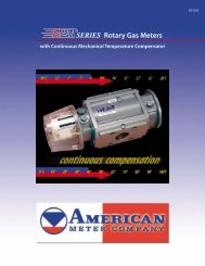
RPM Series Rotary Meters<br />
American Meter’s RPM Series Rotary Meters provide<br />
accurate flow measurement <strong>and</strong> outst<strong>and</strong>ing performance<br />
for commercial <strong>and</strong> industrial measurement applications.<br />
These meters feature an extruded aluminum housing<br />
that provides superior strength, making them ideal<br />
for service where pipe stress <strong>and</strong> snap-acting loads<br />
can occur.<br />
All RPM Series meters mount in either a horizontal<br />
or vertical position, depending on available space <strong>and</strong><br />
convenience. Once installed, all st<strong>and</strong>ard <strong>and</strong> optional<br />
equipment can be easily positioned for convenient reading<br />
<strong>and</strong> quick service. All models have extremely good<br />
rangeability <strong>and</strong> are available in various pipe sizes to<br />
meet a variety of applications.<br />
In-depth details of these various configurations can<br />
be found in the following sales bulletins:<br />
SB 5500 RPM Meter<br />
SB 5510 RPM Meter with Mercury Corrector<br />
SB 5520 RPM-CMTC<br />
RPM Series meters are available in the following<br />
configurations:<br />
RPM-Std<br />
St<strong>and</strong>ard meter with<br />
uncorrected mechanical<br />
register<br />
RPM-ETC<br />
Meter with uncorrected<br />
mechanical register <strong>and</strong><br />
battery powered electronic<br />
temperature compensator<br />
RPM-ID<br />
Meter with uncorrected mechanical register<br />
<strong>and</strong> instrument drive for mounting a pressure/<br />
temperature corrector<br />
RPM-CMTC<br />
Meter with<br />
continuous<br />
mechanical<br />
temperature<br />
compensator<br />
RPM-CMTC-ID<br />
Meter with continuous<br />
mechanical temperature<br />
compensator <strong>and</strong> instrument<br />
drive for mounting<br />
a pressure-compensating<br />
index or pressurecorrecting<br />
instrument<br />
RPM w/Mercury<br />
Meter with integral Mercury<br />
Instrument for pressure/<br />
temperature correction
RPM Series Rotary Meters continued<br />
A six-month history is available through the Electronic<br />
Temperature Compensator’s (ETC) data files, which can<br />
easily be accessed using software (TCDAS 2000) via a<br />
laptop computer or Palm H<strong>and</strong>held PDA connected to<br />
the unit’s interface port. The ETC’s memory stores corrected<br />
<strong>and</strong> uncorrected volume once a month at a userdesignated<br />
day <strong>and</strong> time. This information is obtainable<br />
for the six previous months of operation in a separate<br />
data file.<br />
Meter Capacities<br />
RPM Series Rotary Meter Capacities *<br />
scfh (Sm3 /h)<br />
Line<br />
Pressure 8.0C 9.0C 11C 1.5M 2M 3.5M 5.5M 7M 11M 16M<br />
0.25 psig 800 900 1,100 1,500 2,000 3,500 5,500 7,000 11,000 16,000<br />
(17 mBarg) (22.4) (25.2) (30.8) (42.0) (56.0) (98.0) (154.0) (196.0) (308.0) (448.0)<br />
2 psig 891 1,002 1,225 1,670 2,227 3,897 6,124 7,794 12,247 17,814<br />
(1.4 mBarg) (24.9) (28.1) (34.3) (46.8) (62.3) (109.1) (171.5) (218.2) (342.9) (498.8)<br />
5 psig 1,054 1,185 1,449 1,976 2,634 4,610 7,244 9,219 14,487 21,073<br />
(345 mBarg) (29.5) (33.2) (40.6) (55.3) (73.8) (129.1) (202.8) (258.1) (405.6) (590.0)<br />
10 psig 1,325 1,491 1,822 2,485 3,313 5,798 9,111 11,595 18,221 26,504<br />
(690 mBarg) (37.1) (41.7) (51.0) (69.6) (92.8) (162.3) (255.1) (324.7) (510.2) (742.1)<br />
25 psig 2,140 2,407 2,942 4,012 5,350 9,362 14,711 18,724 29,423 42,797<br />
(1.7 Barg) (59.9) (67.4) (82.4) (112.3) (149.8) (262.1) (411.9) (524.3) (823.8) (1,198.3)<br />
50 psig 3,498 3,935 4,809 6,558 8,744 15,302 24,046 30,604 48,092 69,952<br />
(3.4 Barg) (97.9) (110.2) (134.7) (183.6) (244.8) (428.5) (673.3) (856.9) (1,346.6) (1,958.7)<br />
75 psig 4,855 5,462 6,676 9,104 12,138 21,242 33,381 42,485 66,762 97,108<br />
(5.2 Barg) (136.0) (152.9) (186.9) (254.9) (339.9) (594.8) (934.7) (1,189.6) (1,869.3) (2,719.0)<br />
100 psig 6,213 6,990 8,543 11,650 15,533 27,183 42,716 54,365 85,431 124,263<br />
(6.9 Barg) (174.0) (195.7) (239.2) (326.2) (434.9) (761.1) (1,196.0) (1,522.2) (2,392.1) (3,479.4)<br />
150 psig 8,929 10,045 12,277 16,741 22,322 39,063 61,385 78,126 122,770 178,574<br />
(10.3 Barg) (250.0) (281.3) (343.8) (468.8) (625.0) (1,093.8) (1,718.8) (2,187.5) (3,437.6) (5,000.1)<br />
175 psig 10,286 11,572 14,144 19,287 25,716 45,003 70,720 90,007 141,439 205,730<br />
(12.1 Barg) (288.0) (324.0) (396.0) (540.0) (720.1) (1,260.1) (1,980.1) (2,520.2) (3,960.3) (5,760.4)<br />
200 psig 11,644 14,585 17,826 24,308 32,411 56,719 89,130 113,439 178,261 259,288<br />
(13.8 Barg) (326.0) (408.4) (499.1) (680.6) (907.5) (1,588.1) (2,495.7) (3,176.3) (4,991.3) (7,260.1)<br />
250 psig 14,360 16,155 19,745 26,925 35,900 62,824 98,724 125,648 197,447 287,196<br />
(17.2 Barg) (402.1) (452.3) (552.9) (753.9) (1,005.2) (1,759.1) (2,764.3) (3,518.2) (5,528.5) (8,041.5)<br />
285 psig 16,261 18,293 22,358 30,489 40,652 71,141 111,792 142,281 223,585 325,214<br />
(19.6 Barg) (455.3) (512.2) (626.0) (853.7) (1,138.2) (1,991.9) (3,130.2) (3,983.9) (6,260.4) (9,106.0)<br />
* Capacity data based upon natural gas with specific gravity of 0.60.<br />
9
10<br />
Turbine Meters<br />
American Meter supplies several variations of compact,<br />
high-performance turbine meters. Each of these variations<br />
is designed to provide accurate totalization of high<br />
volume gas flows.<br />
GTS meters are available in line sizes from 3" to 12"<br />
<strong>and</strong> pressure ratings up to 1,440 psig. The 4", 6" <strong>and</strong> 8"<br />
sizes are available with extended capacity ratings (30°<br />
rotor), which can reduce the pipe size of an entire meter<br />
run, resulting in substantial savings.<br />
GTX meters are available in line sizes from 4" to 8" <strong>and</strong><br />
a pressure rating of 175 psig. These meters are a costreduced<br />
version of the GTS meter specifically designed<br />
for in-plant measurement or where reduced maintenance<br />
is a requirement.<br />
GTS, GTX <strong>and</strong> AccuTest<br />
turbine meters are supported<br />
by low (350 cubic<br />
foot bell <strong>and</strong> large sonicnozzle<br />
provers), medium<br />
(150 psia recirculatingair<br />
test loop with master<br />
turbine meters as a reference<br />
st<strong>and</strong>ard) <strong>and</strong> high<br />
(natural gas test pressures<br />
up to 1,000 psia with<br />
master turbine meters<br />
as reference st<strong>and</strong>ard)<br />
test facilities.<br />
Designed for reliable, long-term service, these meters<br />
feature:<br />
• flush-type bearing lubrication system (GTS <strong>and</strong><br />
AccuTest);<br />
• aluminum rotors for high-pressure models <strong>and</strong> meters<br />
with high-frequency pulse output (GTS <strong>and</strong> AccuTest);<br />
• high-frequency RF pulser that monitors rotor condition<br />
(GTS <strong>and</strong> AccuTest);<br />
• one output gear train for 3" to 8" meters reduces spare<br />
parts inventory;<br />
• high-efficiency inlet flow conditioners;<br />
• interchangeable pre-calibrated cartridges for easy<br />
maintenance/change out;<br />
• optional electronic temperature compensation; <strong>and</strong><br />
• optional fixed-factor pressure compensation.<br />
In-depth details of GTS <strong>and</strong> GTX turbine meters can<br />
be found in bulletin SB 4510.<br />
3" GTS Meter 4" GTS Meter
Turbine Meters continued<br />
AccuTest Transfer Proving Turbine Meters<br />
These innovative units combine all the features <strong>and</strong><br />
benefits of American Meter’s GTS turbine meters with<br />
an additional integral reference meter that provides<br />
on-site, in-line testing under actual operating conditions.<br />
Transfer proving has graduated to on-site, in-line turbine<br />
meter testing. On-screen diagnostics <strong>and</strong> one-minute<br />
test cycles assure precise accuracy <strong>and</strong> reduce the cost<br />
of periodic testing.<br />
Meter Capacities<br />
An AccuTest meter, with your laptop computer, becomes<br />
a transfer proving system, without removing the cartridge<br />
from the meter. AccuTest meters are available in<br />
4", 6" <strong>and</strong> 8" sizes, with st<strong>and</strong>ard or extended capacity<br />
aluminum rotors.<br />
In-depth details of the AccuTest turbine meter can be<br />
found in bulletin SB 4515.<br />
AccuTest meters combine a high-performance turbine<br />
meter with an integral test meter for on-site, in-line<br />
testing under actual operating conditions.<br />
Turbine Meter Capacities *<br />
mscfh (Sm3 4" GTS, GTX or AccuTest<br />
/h)<br />
6" GTS, GTX or AccuTest 8" GTS, GTX or AccuTest<br />
Line 3" GTS 45° Rotor 30° Rotor 45° Rotor 30° Rotor 45° Rotor 30° Rotor 12" GTS<br />
Pressure Cap. Range Cap. Range Cap. Range Cap. Range Cap. Range Cap. Range Cap. Range Cap. Range<br />
0.25 psig<br />
(17 mBarg)<br />
10<br />
(280)<br />
12:1<br />
18<br />
(504)<br />
15:1<br />
23<br />
(644)<br />
12:1<br />
35<br />
(980)<br />
18:1<br />
50<br />
(1,400)<br />
12:1<br />
60<br />
(1,680)<br />
20:1<br />
88<br />
(2,464)<br />
15:1<br />
150<br />
(4,200)<br />
25:1<br />
10 psig 17<br />
30<br />
38<br />
58<br />
93<br />
100<br />
146<br />
250<br />
15:1<br />
19:1<br />
15:1<br />
23:1<br />
15:1<br />
26:1<br />
19:1<br />
(690 mBarg) (476) (840) (1,064) (1,624) (2,604) (2,800) (4,088) (7,000)<br />
25 psig 27<br />
48<br />
62<br />
94<br />
134<br />
161<br />
237<br />
404<br />
20:1<br />
25:1<br />
20:1<br />
29:1<br />
25:1<br />
33:1<br />
25:1<br />
(1.7 Barg) (756) (1,344) (1,736) (2,632) (3,752) (4,508) (6,636) (11,312)<br />
50 psig 44<br />
80<br />
102<br />
154<br />
220<br />
265<br />
388<br />
662<br />
25:1<br />
31:1<br />
25:1<br />
38:1<br />
25:1<br />
42:1<br />
31:1<br />
(3.4 Barg) (1,232) (2,240) (2,856) (4,312) (6,160) (7,420) (10,864) (18,536)<br />
100 psig 79<br />
142<br />
182<br />
276<br />
395<br />
474<br />
695<br />
1,185<br />
33:1<br />
42:1<br />
33:1<br />
50:1<br />
33:1<br />
56:1<br />
42:1<br />
(6.9 Barg) (2,212) (3,976) (5,096) (7,728) (11,060) (13,272) (19,460) (33,180)<br />
500 psig 379<br />
695<br />
872<br />
1,328<br />
1,897<br />
2,276<br />
3,339<br />
5,691<br />
71:1<br />
89:1<br />
71:1<br />
106:1<br />
71:1<br />
118:1<br />
89:1<br />
(34.4 Barg) (10,612) (19,460) (24,416) (37,184) (53,116) (63,728) (93,492) (159,348)<br />
1,000 psig 814<br />
1,466<br />
1,873.0<br />
2,851<br />
4,072<br />
4,887<br />
7,167.0 12,217<br />
100:1<br />
124:1<br />
100:1<br />
149:1<br />
100:1<br />
166:1<br />
124:1<br />
(68.9 Barg) (22,792) (41,048) (52,444) (79,828) (114,016) (136,836) (200,676) (342,076)<br />
1,400 psig 1,197<br />
2,154<br />
2,754<br />
4,190<br />
6,041<br />
7,184<br />
10,536 17,959<br />
118:1<br />
147:1<br />
118:1<br />
176:1<br />
118:1<br />
196:1<br />
147:1<br />
(96.5 Barg) (33,516) (60,312) (77,112) (117,320) (169,148) (201,152) (295,008) (502,852)<br />
32:1<br />
41:1<br />
52:1<br />
70:1<br />
148:1<br />
207:1<br />
245:1<br />
11
12<br />
Selecting the Correct<br />
Pressure Regulator<br />
American Meter pressure regulators are used (a)<br />
upstream of a gas meter to reduce inlet pressure to the<br />
meter <strong>and</strong> eliminate fluctuations, which can affect meter<br />
accuracy <strong>and</strong> (b) downstream of the gas meter to provide<br />
reduced pressure for gas-operated equipment.<br />
The three major factors that determine the selection<br />
of a pressure regulator are as follows:<br />
• inlet pressure to the regulator (minimum <strong>and</strong> maximum)<br />
• outlet pressure that the regulator must maintain<br />
• required capacity of the regulator in scfh (Sm 3 /h)<br />
American Meter offers a wide variety of regulators<br />
to meet almost any application as shown in the charts<br />
to the right.<br />
In addition to the three major factors above, there are<br />
various options available in regulators that should be<br />
considered. American Meter offers different regulator<br />
models that include options for protection against upset<br />
conditions. The most common of these options include:<br />
• internal relief (partial or full) – the ability to vent excess<br />
gas to atmosphere in the event the outlet pressure<br />
rises above a predetermined value<br />
• overpressure shut-off (OPSO) – the ability to shut<br />
down the gas supply if outlet pressure exceeds<br />
a predetermined value<br />
• underpressure shut-off (UPSO) – the ability to shut<br />
down the gas if the outlet pressure falls below a<br />
predetermined value<br />
• remote monitoring – the ability to control/monitor<br />
pressure at a specified location downstream of<br />
the regulator<br />
Maximum Inlet Pressure Ratings<br />
REGULATORS<br />
3000<br />
Industrial<br />
1800PFM<br />
Industrial<br />
2000<br />
Industrial<br />
1800<br />
Industrial<br />
1800CPB2<br />
1800C<br />
1800B2<br />
1200<br />
CR4000<br />
Outlet Pressure Range<br />
REGULATORS<br />
3000<br />
Industrial<br />
1800PFM<br />
Industrial<br />
2000<br />
Industrial<br />
1800<br />
Industrial<br />
1800CPB2<br />
1800C<br />
1800B2<br />
1200<br />
CR4000<br />
Maximum Rated Capacities<br />
REGULATORS<br />
3000<br />
Industrial<br />
1800PFM<br />
Industrial<br />
2000<br />
Industrial<br />
1800<br />
Industrial<br />
1800CPB2<br />
1800C<br />
1800B2<br />
1200<br />
CR4000<br />
MAXIMUM INLET PRESSURE RATINGS<br />
30 psig (2.0 Barg)<br />
150 psig (10.3 Barg)<br />
150 psig (10.3 Barg)<br />
150 psig (10.3 Barg)<br />
125 psig (8.6 Barg)<br />
125 psig (8.6 Barg)<br />
125 psig (8.6 Barg)<br />
125 psig (8.6 Barg)<br />
125 psig (8.6 Barg)<br />
OUTLET PRESSURE RANGES<br />
1" w.c. to 2 psig (2 to 138 mBarg)<br />
0.5 to 30 psig (34 mBarg to 2.0 Barg)<br />
0.5 to 15 psig<br />
(34 mBarg to 1.0 Barg)<br />
3.5" w.c. to 5 psig<br />
(9 to 345 mBarg)<br />
1 to 30 psig (69 mBarg to 2.0 Barg)<br />
3.5" w.c. to 2 psig (9 to 138 mBarg)<br />
3.5" w.c. to 2 psig (9 to 138 mBarg)<br />
3.5" w.c. to 5 psig (9 to 345 mBarg)<br />
3.5" w.c. to 5 psig (9 to 345 mBarg)<br />
MAXIMUM RATED CAPACITIES<br />
90,000 scfh (2,549 Sm 3 /h)<br />
60,000 scfh (1,699 Sm 3 /h)<br />
20,000 scfh (566.3 Sm 3 /h)<br />
10,200 scfh (288.8 Sm 3 /h)<br />
4,900 scfh (138.7 Sm 3 /h)<br />
4,600 scfh (130.2 Sm 3 /h)<br />
2,500 scfh (70.8 Sm 3 /h)<br />
2,100 scfh (59.4 Sm 3 /h)<br />
20,000 scfh (566.3 Sm 3 /h)
Pressure Regulators<br />
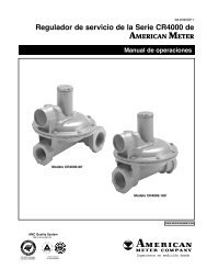
Series CR4000 Regulators<br />
• type: lever-type, spring-loaded<br />
• maximum rated capacity:<br />
2,100 scfh (59.4 Sm 3 /h)<br />
• maximum inlet pressure:<br />
125 psig (8.6 Barg)<br />
• outlet pressure range:<br />
3.5" w.c. to 5 psig<br />
(9 to 345 mBarg)<br />
• connection sizes:<br />
3/4" to 1" NPT or<br />
BSP-TR<br />
• available options: full internal relief<br />
• Bulletin SB 8580<br />
1200 Series Regulators<br />
• type: lever-type, spring-loaded<br />
• maximum rated capacity:<br />
2,500 scfh (70.8 Sm 3 /h)<br />
• maximum inlet pressure:<br />
125 psig (8.6 Barg)<br />
• outlet pressure range:<br />
3.5" w.c. to 5 psig<br />
(9 to 345 mBarg)<br />
• connection sizes:<br />
1/2", 3/4" or 1"<br />
NPT or BSP-TR<br />
• available options:<br />
full internal relief, OPSO, UPSO, USSA<br />
• Bulletin SB 8505 (Series 1200)<br />
• Bulletin SB 8506 (Model 1213B2)<br />
• Bulletin SB 8556 (USSA)<br />
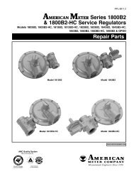
1800B2/1800B2-HC Series Regulators<br />
• type: lever-type, spring-loaded<br />
• maximum rated capacity:<br />
4,600 scfh (130.2 Sm 3 /h)<br />
• maximum inlet pressure:<br />
125 psig (8.6 Barg)<br />
• outlet pressure range:<br />
3.5" w.c. to 2 psig<br />
(9 to 138 mBarg)<br />
• connection sizes:<br />
3/4", 1" or 1-1/4" NPT or BSP-TR<br />
• available options: full internal relief, partial internal<br />
relief, OPSO, UPSO, USSA<br />
• Bulletin SB 8510 (1800B2/1800B2-HC)<br />
• Bulletin TDB 8620 (1843B2-L)<br />
• Bulletin SB 8556 (USSA)<br />
1800C/1800C-HC Series Regulators<br />
• type: lever-type, spring-loaded<br />
• maximum rated capacity:<br />
4,900 scfh<br />
(138.7 Sm 3 /h)<br />
• maximum inlet<br />
pressure:<br />
125 psig (8.6 Barg)<br />
• outlet pressure range:<br />
3.5" w.c. to 2 psig<br />
(9 to 138 mBarg)<br />
• connection sizes: 3/4", 1" or 1-1/4" NPT or BSP-TR<br />
• available options: full internal relief, OPSO, UPSO,<br />
USSA<br />
• Bulletin SB 8515<br />
• Bulletin SB 8556 (USSA)<br />
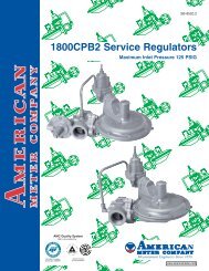
1800CPB2 Series Pilot-Loaded Regulators<br />
• type: lever-type, pilot-loaded<br />
• maximum rated capacity:<br />
10,200 scfh (288.8 Sm 3 /h)<br />
• maximum inlet pressure:<br />
125 psig (8.6 Barg)<br />
• outlet pressure range:<br />
1 to 30 psig<br />
(69 mBarg to 2.0 Barg)<br />
• connection sizes: 3/4",<br />
1" or 1-1/4" NPT or BSP-TR<br />
• available options: OPSO<br />
• Bulletin SB 8520<br />
13
14<br />
Pressure Regulators continued<br />
1800 Series Industrial Regulators<br />
• type: lever-type, spring-loaded<br />
• maximum rated capacity:<br />
20,000 scfh (566.3 Sm 3 /h)<br />
• maximum inlet pressure:<br />
150 psig (10.3 Barg)<br />
• outlet pressure range:<br />
3.5" w.c. to 5 psig<br />
(9 to 345 mBarg)<br />
• connection sizes:<br />
1-1/2" or 2" NPT/BSP-TR<br />
2" flanged<br />
• available options: full internal relief, partial<br />
internal relief, USSA, OPSO, UPSO, external<br />
sensing<br />
• Bulletin SB 8540<br />
• Bulletin SB 8745 (USSA)<br />
2000 Series Industrial Regulators<br />
• type: lever-type, spring-loaded<br />
• maximum rated capacity:<br />
20,000 scfh (566.3 Sm 3 /h)<br />
• maximum inlet pressure:<br />
150 psig (10.3 Barg)<br />
• outlet pressure range:<br />
0.5 to 15 psig<br />
(34 mBarg to<br />
1.0 Barg)<br />
• connection sizes:<br />
1/2" or 2" NPT/BSP-TR, 2" flanged<br />
• available options: OPSO, UPSO, USSA, external<br />
sensing<br />
• Bulletin SB 8540<br />
• Bulletin SB 8745 (USSA)<br />
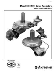
1800PFM Series Industrial Regulators<br />
• type: lever-type, pilot-loaded<br />
• maximum rated capacity:<br />
60,000 scfh (1,699 Sm 3 /h)<br />
• maximum inlet pressure:<br />
150 psig (10.3 Barg)<br />
• outlet pressure range:<br />
0.5 to 30 psig<br />
(34 mBarg to 2.0 Barg)<br />
• connection sizes: 1-1/2" to<br />
2" NPT/BSP-TR, 2" flanged<br />
• available options: OPSO, UPSO,<br />
USSA, external sensing<br />
• Bulletin SB 8551<br />
• Bulletin SB 8745 (USSA)<br />
Series 3000 Industrial Regulators<br />
• type: direct-acting, spring-loaded<br />
• maximum rated capacity:<br />
90,000 scfh (2,549 Sm 3 /h)<br />
• maximum inlet pressure:<br />
30 psig (2.0 Barg)<br />
• outlet pressure range:<br />
1" w.c. to 2 psig<br />
(2 to 138 mBarg)<br />
• connection sizes: 1-1/4", 1-1/2"<br />
or 2" NPT/BSP-TR, 2", 3" or 4"<br />
flanged<br />
• available options: external sensing<br />
• Bulletin SB 8535
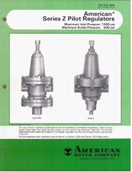
High-Pressure Regulators<br />
American Meter offers several variations of pilot-loaded<br />
pressure/flow control regulators for use in applications<br />
such as gas pipeline, transmission <strong>and</strong> distribution<br />
systems. These regulators are also capable of<br />
delivering gas to large industrial complexes that<br />
require high pressures <strong>and</strong>/or flow rates.<br />
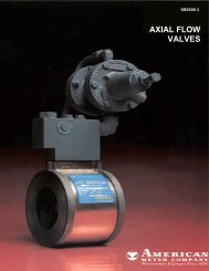
Both the Axial Flow Valve (AFV) <strong>and</strong> Radial Flow Valve<br />
(RFV) utilize a durable flexible element that opens or<br />
closes the valve, dependent upon the differential<br />
pressure across it. Integral to the valves are pilots<br />
that control the differential pressure across the flexible<br />
element by sensing downstream dem<strong>and</strong> (or upstream<br />
pressure in relief/backpressure mode), making the<br />
complete system a pressure regulator. Because of this<br />
unique design, these regulators are extremely versatile<br />
<strong>and</strong> work in a variety of applications. The most common<br />
applications are as follows:<br />
• pressure regulation<br />
– single-stage pressure reduction<br />
– two-stage pressure reduction<br />
– pressure reduction with monitor used for<br />
overpressure protection<br />
– two-stage pressure reduction with monitor override<br />
(working monitor)<br />
• overpressure relief/backpressure<br />
• underpressure shutoff<br />
• flow control<br />
• on/off valve<br />
Axial <strong>and</strong> Radial Flow Valves<br />
Principle of Operation<br />
Axial <strong>and</strong> Radial Flow Valves are unique in that there<br />
is no mechanical connection to the control element.<br />
Instead, the valves use an elastomer sleeve or<br />
diaphragm, which exp<strong>and</strong>s or contracts depending on<br />
the pressure differential across the valve. This principle<br />
provides a valve that is extremely compact <strong>and</strong> lightweight<br />
with a streamlined flow path for quiet operation.<br />
Radial Flow Valve<br />
with 60Series Pilot<br />
St<strong>and</strong>ard flexible element materials provide a wide working<br />
temperature range <strong>and</strong> excellent resistance to abrasion<br />
<strong>and</strong> swelling. Specialized materials are also available<br />
for applications involving extreme temperatures, where<br />
additional chemical resistance is required <strong>and</strong> for<br />
specialized services such as water scarfing.<br />
<strong>Control</strong> Pilots<br />
Various spring-loaded pilot regulators are utilized to<br />
balance the pressure applied to the control port of the<br />
Axial Flow Valve. It is actually the choice of pilot that<br />
determines the function (pressure reduction or backpressure)<br />
<strong>and</strong> outlet pressure or relief setting.<br />
Further information about the Axial Flow Valve can be<br />
found in SB 9509 <strong>and</strong> TDB 9610. The Radial Flow valve<br />
is featured in SB 9530 <strong>and</strong> TDB 9630. Information on<br />
the 60Series Pilot is in SB 9800.<br />
60Series Pilot<br />
Axial Flow Valve<br />
with 60Series Pilot<br />
15
16<br />
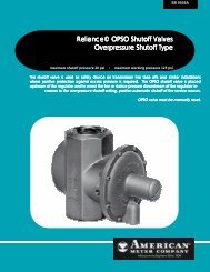
Overpressure Shutoff<br />
Safety Devices<br />
Overpressure shutoff valves are typically placed<br />
upstream of a pressure regulator. In the event of a<br />
regulator failure, these units provide rapid automatic<br />
<strong>and</strong> positive shutoff of gas service, protecting the<br />
regulator, meter <strong>and</strong> other downstream equipment.<br />
Overpressure<br />
Shutoff<br />
Valve<br />
Universal Safety Shutoff Assembly (USSA)<br />
• maximum inlet pressure:<br />
150 psig (10.3 Barg)<br />
• OPSS shutoff pressure<br />
range: 7.5" w.c. to 35 psig<br />
(19 mBarg to 2.4 Barg)<br />
• UPSS shutoff pressure<br />
range: 3" to 60" w.c.<br />
(7 mBarg to 149 mBarg)<br />
• connection sizes:<br />
1-1/2" or 2"<br />
NPT/BSP-TR;<br />
2" flanged<br />
• available options: overpressure shutoff (OPSS),<br />
underpressure shutoff (UPSS), OPSS/UPSS or<br />
external sensing<br />
• Bulletin SB 8745<br />
Series 100 Slamshut<br />
• maximum inlet pressure:<br />
235 psig (16.2 Barg)<br />
• OPSS shutoff pressure<br />
range: 14" w.c. to<br />
87 psig (35 mBarg<br />
to 6.0 Barg)<br />
• connection sizes:<br />
2", 3" or 4" flanged<br />
• available options:<br />
external sensing<br />
(st<strong>and</strong>ard)<br />
• Bulletin SB 8575<br />
Sensing Line<br />
Regulator<br />
Filters<br />
American Meter filters effectively remove dirt, pipe<br />
scale <strong>and</strong> other particulate from gas lines, protecting<br />
meters, regulators <strong>and</strong> downstream gas equipment.<br />
Filters with either screwed or flanged connections for<br />
medium to high flow rates are available to meet nearly<br />
any gas filtration application. In addition, pilot-type<br />
filters are available for protection of pilot-loaded regulators<br />
where particulate can cause variances in system<br />
pressures.<br />
Pilot-Type Filters<br />
• maximum inlet pressure:<br />
1,000 psig (69 Barg)<br />
• filter element:<br />
5 micron<br />
• connection sizes:<br />
1/4" x 90° or 1/4" x 180°<br />
• Bulletin SB 12521<br />
Screwed Filters<br />
• maximum inlet pressure:<br />
160 psig (11 Barg)<br />
• filter element:<br />
5 micron<br />
• connection sizes:<br />
3/4", 1", 1-1/2" or 2" NPT/BSP-TR<br />
• Bulletin SB 12521<br />
Flanged Filters<br />
• maximum inlet pressure:<br />
1,440 psig (99.2 Barg)<br />
• filter element: 10 (st<strong>and</strong>ard)<br />
or 25 micron<br />
• connection sizes: 2" NPT, 2",<br />
3", 4", 6", 8", 10" or 12" flanged<br />
• special designs available<br />
upon request<br />
• Bulletin SB 12521
Repair Parts <strong>and</strong> Accessories<br />
Quality OEM parts should<br />
always be used when repairing<br />
or upgrading American Meter<br />
equipment to ensure proper<br />
performance <strong>and</strong> longevity<br />
of service life. All repair components meet original<br />
manufacture specifications <strong>and</strong> strictly adhere to our<br />
internal quality assurance program.<br />
American Meter also offers various meter <strong>and</strong> regulator<br />
accessories for use in a wide variety of gas measurement<br />
<strong>and</strong> control applications. For in-depth details on<br />
these products, see the individual data sheets pertaining<br />
to each product.<br />
Meter Connections<br />
American Meter’s connections are used to connect<br />
diaphragm meters to pipe sizes up to 2". A wide variety<br />
of swivel connections simplify connection into rigid<br />
piping systems. These units, available in straight <strong>and</strong><br />
offset configurations, also adapt between different<br />
connections on pipe <strong>and</strong> meter. Insulated types protect<br />
against electrolytic corrosion by preventing induced<br />
currents from reaching pipelines.<br />
For more information,<br />
see Bulletin SB 3910.<br />
Meter Bars<br />
Meter bars prevent stress<br />
from being transferred from<br />
piping to a gas meter <strong>and</strong><br />
simplify the installation of<br />
pressure regulators. The bar<br />
has a threaded connector for<br />
the meter outlet piping <strong>and</strong><br />
clamps around the outlet of<br />
the pressure regulator, providing<br />
a rock-solid installation.<br />
For further information, see<br />
Bulletin SB 6565.<br />
Needle Valves<br />
Needle valves are used<br />
for applications such as orifice<br />
meter gage line connections, shutoff<br />
valves<br />
for pressure gages, odorizers,<br />
sampling devices <strong>and</strong> other<br />
high-pressure control<br />
applications. American<br />
Meter needle valve bodies<br />
are constructed of<br />
stainless steel (with<br />
electropolish<br />
finish) or carbon steel<br />
(with nickel-plated finish) bar stock.<br />
These high-pressure valves are rated for 10,000 psig at<br />
200°F <strong>and</strong> utilize a chemical resistant viton o-ring <strong>and</strong><br />
Teflon back-up ring.<br />
For more information, see Bulletin DS 11521.<br />
Regulator Vent Splashguards<br />
When regulator vents freeze over, the top diaphragm<br />
chamber may be prevented from breathing, resulting<br />
in high fluctuations in outlet pressures. The use of<br />
American Meter splashguards is a quick <strong>and</strong> simple<br />
solution to this problem <strong>and</strong> assures constant <strong>and</strong><br />
reliable gas service.<br />
For further<br />
information, see<br />
Bulletin 90710.<br />
17
18<br />
TRACE TM VRT TM Mobile AMR System<br />
from AMCO Automated Systems<br />
The TRACE VRT (virtual real time), mobile AMR system,<br />
processes <strong>and</strong> stores real-time data at the electric, gas<br />
or water meter transponder (Meter Interface Unit or<br />
MMI) for retrieval as required during a normal in-cycle<br />
read. Stored data includes 35 days of daily index readings<br />
(each in a separate electronic index [e-index]), up to<br />
six time-of-use (TOU) e-indexes (four for gas <strong>and</strong> water<br />
applications <strong>and</strong> six for electric) <strong>and</strong> a leak-detection<br />
alarm (water). A real-time clock in the transponder<br />
allows time-based data collection.<br />
The daily index-read-time is factory <strong>and</strong> field programmable,<br />
as is the start <strong>and</strong> stop times of each TOU e-index<br />
<strong>and</strong> the duration of the leak-detection monitoring interval<br />
<strong>and</strong> threshold level. Data is read from mobile interrogators,<br />
using two-way RF communication technology. TRACE<br />
VRT transponders are addressed individually by serial<br />
number, followed by a series of comm<strong>and</strong>s to retrieve<br />
specific daily readings <strong>and</strong> time-of-use data, as well as<br />
the usual accumulated volume <strong>and</strong> alarms.<br />
As shown below, TRACE VRT is a complete system,<br />
comprised of meter transponders, h<strong>and</strong>-held <strong>and</strong> or<br />
vehicle-mounted interrogators <strong>and</strong> host software that<br />
integrate utility CIS systems with metering data in<br />
the field.<br />
TRACE VRT host software, Route Manager VRT:<br />
• accepts customer account <strong>and</strong> route data files from<br />
one or more electric, gas <strong>and</strong>/or water utility Customer<br />
Information Systems (CIS)<br />
• stores the CIS data in a MS SQL server database<br />
• supports the management of the read routes stored<br />
in the SQL database<br />
• assigns <strong>and</strong> downloads read routes to interrogation<br />
devices<br />
• uploads meter data from interrogation devices<br />
• stores up to 13 months of meter data in the SQL database<br />
for local validation, editing <strong>and</strong> analysis using builtin<br />
ODBC applications or Microsoft Office applications<br />
such as Excel<br />
• uploads meter-data files to one or more utility CIS’s<br />
H<strong>and</strong>-held interrogators are used to read electric, gas<br />
or water routes following address-sequenced routes with<br />
each meter reading initiated by an operator. The Mini-<br />
Mobile Interrogator (MMI) is a vehicle-transported device<br />
that can be used to read electric, gas <strong>and</strong>/or water routes<br />
automatically based on the geographical location of the<br />
vehicle <strong>and</strong> individual meters. The Vehicle Interactive<br />
Display (VID) displays real-time vehicle <strong>and</strong> meter locations,<br />
as well as the reading status of each meter.
Direct Gas Transponder (DGT)<br />
The DGT is designed for use<br />
with most residential <strong>and</strong> small<br />
commercial diaphragm meters<br />
from American Meter Company ® ,<br />
Rockwell/Equimeter/Invensys ® ,<br />
<strong>and</strong> Sprague/Schlumberger/Actarus ® . The DGT mounts<br />
directly on a meter, incorporating the mechanical index<br />
<strong>and</strong> index cover supplied as part of the meter.<br />
Pit Water Transponder (PWT)<br />
The PWT is designed for use with<br />
water meters installed below grade<br />
in pits <strong>and</strong> is compatible with most<br />
AMCO/ABB, Senus/Rockwell,<br />
Neptune, Badger, Hersey <strong>and</strong><br />
Metron-Farnier water meters. The PWT is extremely<br />
compact <strong>and</strong> is installed on the underside of the pit lid<br />
with the antenna extending through the st<strong>and</strong>ard 1-3/4"<br />
hole <strong>and</strong> held in place by a low-profile cap from the topside<br />
of the lid.<br />
Remote Water Transponder (RWT)<br />
The RWT is designed for use with<br />
water meters installed above grade.<br />
It can be wall mounted indoors or<br />
outdoors <strong>and</strong> is compatible with<br />
most AMCO/ABB, Senus/Rockwell,<br />
Neptune, Badger, Hersey <strong>and</strong> Metron-Farnier water<br />
meters.<br />
Direct Electric Transponder (DET)<br />
The DET is designed for use with<br />
most residential, single-phase,<br />
Form-2S watt-hour meters from<br />
Elster Electric/ABB, Schlumberger/<br />
Sangamo, General Electric <strong>and</strong><br />
L<strong>and</strong>is <strong>and</strong> Gyr. The DET directly mounts in the meter<br />
(under glass).<br />
Mini-Mobile Interrogator (MMI) VRT<br />
The MMI is a Radio Frequency (RF),<br />
drive-by interrogator that establishes<br />
two-way communications with electric,<br />
gas <strong>and</strong> water meters equipped<br />
with TRACE <strong>and</strong> TRACE VRT<br />
transponders based on the geographical location of the<br />
MMI <strong>and</strong> the meters that are within range of the MMI.<br />
Vehicular Interactive Display (VID)<br />
VRT<br />
The VID displays real-time street<br />
maps marking the location of the<br />
meters <strong>and</strong> the MMI as the vehicle<br />
moves through the route. As each<br />
meter is read by the MMI, the graphical representation of<br />
the meter on the VID display changes to show that it<br />
has been read.<br />
Universal Radio Frequency<br />
Interface (URFI) VRT<br />
The URFI is a plug-in adapter that<br />
allows most DOS-compatible, h<strong>and</strong>held<br />
data terminals (HHDT) to function<br />
as a walk-by RF interrogator<br />
that can establish two-way communications with electric,<br />
gas <strong>and</strong> water meters equipped with TRACE <strong>and</strong><br />
TRACE VRT transponders.<br />
Short-Range Programmer<br />
(SRP) VRT<br />
The SRP is a h<strong>and</strong>-held programmer/<br />
interrogator intended for use during<br />
the installation of electric, gas <strong>and</strong><br />
water TRACE <strong>and</strong> TRACE VRT<br />
transponders. The SRP is used to: (1) verify that a<br />
transponder is funtioning correctly <strong>and</strong> (2) initialize the<br />
starting values of various transponder indexes (e-indexes)<br />
<strong>and</strong> associated settings.<br />
Route Manager VRT<br />
The Route Manager VRT is software<br />
that integrates TRACE VRT transponders<br />
<strong>and</strong> interrogators into an<br />
AMR system <strong>and</strong> provides the<br />
interface between the TRACE VRT<br />
AMR system <strong>and</strong> a utility company’s<br />
customer-information system.<br />
19
20<br />
Remeter Services<br />
American Meter Company, the largest supplier of gas<br />
measurement <strong>and</strong> control equipment in North America<br />
offers the broadest product portfolio in the industry.<br />
North American Services Group (NASG), through its<br />
offering of full-service solutions from REverifiction<br />
through REmanufacturing, is the largest meter service<br />
provider.<br />
Today’s utility companies dem<strong>and</strong> accountability <strong>and</strong><br />
efficiency. Our comprehensive <strong>and</strong> strategic programs<br />
allow you to maximize your purchasing, manpower, <strong>and</strong><br />
logistical resources.<br />
NASG brings together the management, engineering,<br />
manufacturing, <strong>and</strong> information systems expertise of<br />
both the American Meter <strong>and</strong> Canadian Meter group of<br />
companies to provide an unparalleled value proposition<br />
to North American utility companies.<br />
Remetering Program<br />
The Remetering Program includes several different<br />
levels to accommodate your needs.<br />
REverify<br />
The REverify program provides the customer with<br />
a st<strong>and</strong>ard process (similar to “Pass Thru” utility<br />
processes) which confirms the measurement <strong>and</strong><br />
pressure integrity of the meter.<br />
Meters only qualify for REverify if in-test<br />
accuracy results are within ±1.0% with<br />
a spread not to exceed 1%. A “theft<br />
awareness” inspection is also performed<br />
at this point. Meters passing these integrity<br />
inspections are then processed to completion,<br />
primed <strong>and</strong> finish painted, <strong>and</strong> have a new index<br />
box installed. St<strong>and</strong>ard processes include:<br />
• visual inspection<br />
• pressure wash<br />
• index test<br />
• prove, bar code <strong>and</strong> document<br />
• additional services as requested<br />
REverify/Adjust<br />
Meters qualify for the REverify <strong>and</strong> Adjust program if<br />
their in-test accuracy results are within ±2.0% with a<br />
spread not to exceed 1%. The REverify <strong>and</strong> Adjust program<br />
offers all the same processes as REverify with the<br />
addition of making adjustments to the meter’s accuracy<br />
to bring it within acceptable limits.<br />
REfurbish<br />
The REfurbish program addresses all makes of meters<br />
that are 20 years old <strong>and</strong> newer. Processes included<br />
are as follows:<br />
• all REverify <strong>and</strong> Adjust processes<br />
• general “above-the-table” cleanup<br />
• inspection, installation of new stuffing box <strong>and</strong> lubrication<br />
• valve grinding<br />
REfurbish Plus<br />
REfurbish Plus refers to all makes of meters that are 30<br />
years old <strong>and</strong> newer. Processes included are as follows:<br />
• all REfurbish processes<br />
• additional replacement parts<br />
<strong>and</strong> services such as pressure<br />
testing at badged maximum<br />
pressure <strong>and</strong> more as<br />
requested
Sub-Meters<br />
QA Turbine Meters<br />
• nominal capacities up to 14,000 scfh (396 Sm3/h)<br />
• maximum pressure rating = 175 psig (12.1 Barg)<br />
• connections: 1" <strong>and</strong> 1-1/2" NPT, 2", 3", 4" flanged<br />
(wafer-style)<br />
• Bulletin DS 4650<br />
USM Ultrasonic Meters<br />
For the measurement of non-flammable gases only<br />
• nominal capacities up to 56,000 scfh (1,586 Sm3/h)<br />
• maximum pressure rating = 175 psig (12.1 Barg)<br />
• connection sizes: 2", 3", 4" or 6" flanged<br />
• st<strong>and</strong>ard low- <strong>and</strong> high-frequency output<br />
• Bulletin SB 6530<br />
BK-G4 Diaphragm Meters<br />
• nominal capacity = 200 scfh (5.7 Sm3/h)<br />
• maximum pressure rating = 5 psig<br />
• top connections<br />
• Bulletin SB 3600<br />
Laboratory Meters<br />
Dry-Test Meter<br />
These meters are used for extremely accurate measurement<br />
of low volumes of any gas that is unsaturated with<br />
water vapor. Volume is read on a large, 6" circular dial<br />
with sweep h<strong>and</strong> <strong>and</strong> four totalizing h<strong>and</strong>s. Units are<br />
available with dial subdivisions as small as 0.001 CF for<br />
very low-volume measurement. For further information,<br />
see Bulletin SB 7510.<br />
Wet-Test Meter<br />
These laboratory instruments are extremely precise<br />
positive-displacement meters which are individually<br />
calibrated under controlled conditions. Using a liquidsealed<br />
rotating drum as the measuring element, these<br />
meters provide large, easy-to-read dials with subdivisions<br />
as low as 0.0005 CF. Models are available calibrated<br />
in CF or liters. For further information, see Bulletin<br />
SB 7520.<br />
QA Turbine Meter<br />
USM Ultrasonic Meter<br />
BK-G4 Diaphragm Meter<br />
Dry-Test Meter<br />
21
Test Equipment<br />
Sub-Meters/In-Plant <strong>Measurement</strong> Devices<br />
SNAP ® Sonic Nozzle Auto Prover<br />
SNAP combines state-of-the-art electronics with precisely<br />
machined sonic nozzles to provide unparalleled speed<br />
<strong>and</strong> accuracy in gas meter proving. SNAP provers:<br />
• dramatically increase productivity by reducing<br />
proving time<br />
• provide bell-prover accuracy with better repeatability<br />
• eliminate the need for environmental controls<br />
• automate data collection <strong>and</strong> reduce operator errors<br />
• occupy about one-half the space of a bell prover<br />
• accommodate all meter br<strong>and</strong>s<br />
For further information, see Bulletin SB 6557.<br />
SNAP/Bell Interface Kit<br />
With the kit, you simply connect the SNAP to any twofoot<br />
or five-foot manual bell prover <strong>and</strong> compare the<br />
SNAP’s proof to the bell. The kit eliminates the need<br />
for a reference (Green Hornet) meter. For further<br />
information, see Bulletin SB 6556.<br />
Sonic-Flow Nozzles<br />
By passing gas or air through a sonic nozzle <strong>and</strong> meter,<br />
<strong>and</strong> using a stopwatch to determine the time needed for<br />
the meter to register the volume, the meter proof can be<br />
calculated. For test pressures from 3.6 to 1000 psig<br />
(24.8 mBar to 69.0 Bar) <strong>and</strong> flow rates to 6000 SCFH<br />
(169.9 SCMH) of gas. For further information, see<br />
Bulletin SB 6640.<br />
Metrology Services<br />
Metrology services are offered through North American<br />
Services Group to better help your meters retain accuracy.<br />
The following proving services are available.<br />
SNAP Provers<br />
• New prover commissioning <strong>and</strong> training<br />
• Basic service <strong>and</strong> recertification<br />
• SNAP to master bell interface<br />
• Custom software<br />
• Networking <strong>and</strong> data collection systems<br />
Bell Provers<br />
• Refurbish – polish bell, oil filtration or change out<br />
• Strapping/bottling<br />
• Master bell certification<br />
• Calibration of automated proving systems<br />
• Regulatory compliance audits<br />
Transfer Provers<br />
• Master meter certification<br />
• Transfer prover upgrades<br />
In addition to proving services, NASG Metrology<br />
Services department offers training in generic meter<br />
proving practices, proving-equipment maintenance <strong>and</strong><br />
in-house measurement training programs. Meter-shop<br />
consultations are also available.<br />
22<br />
SNAP ® Series III Prover<br />
Bell Mate TM
Guide to Other Gases<br />
The meters in this catalog may be used to measure a<br />
wide variety of gases in addition to natural gas. When<br />
using a diaphragm meter, you must account for the fact<br />
that the maximum capacity of the meter will vary with<br />
the specific gravity of the gas being measured.<br />
To accurately size a diaphragm meter, the rated capacity<br />
must be multiplied by a capacity conversion factor (Fg).<br />
Since capacity data for American meters is based on<br />
natural gas, the following table includes capacity conversion<br />
factors which can be used to convert from natural<br />
gas to the specific gas shown.<br />
Table of Measurable Gases<br />
Category A<br />
Under normal use, service life is comparable to naturalgas<br />
service, depending on presence of contaminants.<br />
Category B<br />
Service life varies according to deleterious effects of the<br />
specific gas <strong>and</strong> any contaminants.<br />
For example, the conversion factor for propane is:<br />
Fg =<br />
Fg =<br />
Fg =<br />
Fg = 0.63<br />
S.G. of gas on which rated capacity is based<br />
S.G. of gas to be measured<br />
S.G. of natural gas<br />
S.G. of propane<br />
Specific Specific Gravity Aluminumcase Turbine<br />
Gas Gravity (S.G.) Conversion Factor (Fg) Diaphragm Meters Meters Rotary Meters<br />
Air 1.00 0.77 A A A<br />
Aliphatic Hydrocarbons – (1) A A A<br />
Argon 1.38 0.66 A A A<br />
Butane 2.01 0.55 B B B<br />
Carbon Dioxide (dry) 1.52 0.63 A A A<br />
Carbon Monoxide (dry) 0.97 0.79 B B B<br />
Cyclopropane 1.45 0.64 B B B<br />
Ethane 1.04 0.76 A A A<br />
Ethylene 0.98 0.78 B A B<br />
Helium 0.14 1.15 (2) A A A<br />
Hexafluropropylene (3) 5.18 0.34 B B B<br />
Isobutylene 2.00 0.55 B B B<br />
Krypton 2.82 0.46 A A A<br />
Methane (pure) 0.55 1.04 A A A<br />
Natural Gas 0.60 1.00 A A A<br />
Neon 0.70 0.92 A A A<br />
Nitrogen 0.97 0.79 A A A<br />
Propane 1.53 0.63 A A A<br />
Propylene 1.48 0.64 B A B<br />
Sulfur Hexafluoride 5.11 0.34 B B B<br />
Xenon 4.53 0.36 A A A<br />
0.60<br />
1.53<br />
NOTES:<br />
Do not use American meters to measure oxygen. For<br />
gases not listed <strong>and</strong> high-purity gas applications, consult<br />
your local distributor or contact American Meter.<br />
(1) Conversion factor varies with the specific gravity<br />
of the particular gas.<br />
(2) For very light gases such as hydrogen <strong>and</strong> helium,<br />
the conversion factor method of calculating maximum<br />
capacity may result in excessive mechanical speeds<br />
of the meter. Therefore, the maximum conversion<br />
factor is calculated based on a specific gravity of 0.45.<br />
(3) Also known as perfluropene.<br />
23
Yesterday…Today…Tomorrow 275 Industrial Road<br />
300 Welsh Road, Building One<br />
Horsham, PA 19044-2234<br />
Phone: 215/830-1800<br />
Fax 215/830-1890<br />
www.americanmeter.com<br />
Cambridge, Ontario<br />
Canada N3H 4R7<br />
Phone: 519/650-1900<br />
Fax 519/650-1917<br />
www.canadianmeter.com<br />
Represented by...<br />
Printed in U.S.A. Core – 200 – 4/03<br />
American Meter Company has a program of continuous product development <strong>and</strong> improvement; <strong>and</strong>, therefore, the information in this bulletin is subject to change or modification without notice.