bravo zulu 1/2008 - GL Group
bravo zulu 1/2008 - GL Group
bravo zulu 1/2008 - GL Group
Create successful ePaper yourself
Turn your PDF publications into a flip-book with our unique Google optimized e-Paper software.
Germanischer Lloyd<br />
<strong>bravo</strong> <strong>zulu</strong><br />
Newsletter for Customers and Business Partners Issue 01/<strong>2008</strong><br />
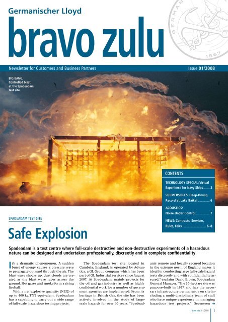
BIg Bang.<br />
controlled blast<br />
at the Spadeadam<br />
test site.<br />
SpadEadam TEST SITE<br />
Safe Explosion<br />
It’s a dramatic phenomenon. A sudden<br />
burst of energy causes a pressure wave<br />
to propagate outward through the air. The<br />
blast wave shocks up, dust clouds are created<br />
as the blast wave races across the<br />
ground. Hot gases and smoke form a rising<br />
fireball.<br />
With a net explosive quantity (NEQ) of<br />
up to 400 kg TNT equivalent, Spadeadam<br />
has a capability to carry out a wide range<br />
of full-scale, hazardous testing projects.<br />
The Spadeadam test site located in<br />
Cumbria, England, is operated by Advantica,<br />
a <strong>GL</strong> <strong>Group</strong> company which has been<br />
part of <strong>GL</strong> Industrial Services since August<br />
2007. At Spadeadam, mainly projects for<br />
the oil and gas industry as well as highly<br />
confidential work for a number of government<br />
agencies are implemented. From its<br />
heritage in British Gas, the site has been<br />
actively involved in the study of largescale<br />
hazards for over 30 years. “Spadead-<br />
conTEnTS<br />
TEchnology SpEcIal: Virtual<br />
Experience for navy Ships ........... 3<br />
SUBmERSIBlES: deep-diving<br />
Record at lake Baikal .................... 6<br />
acoUSTIcS:<br />
noise Under control ....................... 7<br />
nEWS: contracts, Services,<br />
Rules, Fairs ....................................... 6–8<br />
Spadeadam is a test centre where full-scale destructive and non-destructive experiments of a hazardous<br />
nature can be designed and undertaken professionally, discreetly and in complete confidentiality<br />
am’s remote and heavily secured location<br />
in the extreme north of England makes it<br />
ideal for conducting large full-scale hazard<br />
tests discreetly and with confidentiality assured,”<br />
explains David Brown, Spadeadam<br />
General Manager. “The 35-hectare site was<br />
purpose-built in 1977 and has the necessary<br />
infrastructure permanently on site including<br />
a multi-disciplinary team of staff<br />
who have unique experience in managing<br />
hazardous test projects.” Seventeen<br />
<strong>bravo</strong> <strong>zulu</strong> 01/<strong>2008</strong> 1
gaS EXploSIon. The rigs enable real world tests to be conducted at large scale.<br />
separate test facilities are maintained<br />
and constantly being developed to simulate<br />
most of the hazards that the oil and<br />
gas industries could experience. All the<br />
test rigs include advanced data acquisition<br />
systems for comprehensive analysis.<br />
The Spadeadam test site has a wide<br />
range of existing facilities and test rigs with<br />
specialized instrumentation. In addition<br />
scientists and engineers can design and<br />
construct experimental test rigs tailored<br />
to satisfy specific test requirements. Major<br />
projects have involved joint industry<br />
projects in support of the oil and gas industry<br />
and testing new designs and processes<br />
for a range of industries. These include oil<br />
and gas exploration, production and transmission,<br />
water processing and distribution,<br />
and ballistics and defence systems among<br />
many others.<br />
Full-scale fracture propagation of transmission-pipe<br />
and long-term high-pressure<br />
sour-gas corrosion testing of process<br />
equipment have established the site’s<br />
credentials for accurate and reliable data<br />
capture over periods of milliseconds or<br />
months. Gas distribution pipes in polyethylene<br />
are intensively tested to measure the<br />
resistance of material to rapid crack propagation.<br />
Operating conditions can range<br />
from – 20°C and pressures to 30 bar.<br />
The effect of intense jet fires on structures<br />
is met by two flame impingement<br />
test facilities. The test rigs enable full-scale<br />
tests to be conducted with nominal flame<br />
2<br />
<strong>bravo</strong> <strong>zulu</strong> 01/<strong>2008</strong><br />
aREa. Bird‘seye<br />
view of<br />
the test site.<br />
capacity up to 2,000 MW, long-term testing<br />
(longer than one hour) can be sustained at<br />
300 MW. Heat-flux densities and internal<br />
temperature gradients can be readily provided<br />
along with film or video recording<br />
for later analysis.<br />
The effect of gas explosions on structures<br />
are investigated over a wide range<br />
of conditions on a large scale. Fire pressure<br />
transients from explosions can be recorded<br />
of conditions such as variable confinement<br />
or congestion. Alternatively, site<br />
engineers have developed unique facility<br />
to enable pressure transients to be<br />
accurately produced by gas explosions.<br />
These pressure transients can be tailored<br />
from 0 to 7 bar and with periods of 5 ms<br />
to 1 second.<br />
high-sea Testing on dry land<br />
This remote, land-locked location in the<br />
North of England seems an unlikely setting<br />
for maritime tests. But over the years<br />
a great deal of work for the marine sector<br />
has been carried out at Spadeadam and it<br />
is still a feature of current and future trial<br />
activity.<br />
Spadeadam has carried out several ship-<br />
to-ship and ship-to-shore tests looking at<br />
vapour ignition and rapid-phase transition<br />
effects as well as fuel fires and the effects of<br />
blasts against ship structures whilst alongside<br />
a dock.<br />
“The <strong>GL</strong> Industrial Services large-scale<br />
test site is certainly worth serious consideration<br />
if any planned maritime tests or<br />
trials have a significant hazardous component,”<br />
says Brown. The site is currently<br />
exploring the possibility of a series of compartment<br />
fire tests with <strong>GL</strong>IS. This involves<br />
using a representative ship superstructure<br />
whilst keeping a weather-eye on novel and<br />
future fuel technology. ■<br />
For further information: David Brown,<br />
General Manager, Phone: +44 1697749138<br />
E-Mail: david.brown@advanticagroup.com<br />
www.advanticagroup.com/spadeadam<br />
technology special<br />
FIGURE 8. Aerodynamic flow<br />
simulation for frigates.
SImUlaTIon-BaSEd dESIgn<br />
Virtual Experience<br />
for navy Ships<br />
TEchnology SpEcIal<br />
Simulation-based design increasingly replaces traditional experience-based design. an overview of<br />
techniques now used in advanced industry practice, with particular focus on navy applications<br />
by Volker Bertram<br />
Ship design is increasingly supported by<br />
sophisticated analyses. Traditionally,<br />
ship design is based on experience. This is<br />
still true to some extent, but we increasingly<br />
rely on “virtual experience” from dedicated<br />
and well chosen simulations. Scope<br />
and depth of these simulations guiding our<br />
decisions in design and operation of ships<br />
have developed very dynamically over the<br />
past decade. Described is the state of the art<br />
as reflected in the work, but now with particular<br />
focus on applications for navy ships.<br />
1. Structural analyses<br />
1.1 Finite-element analysis<br />
(FEa)<br />
FEA for global strength within the elastic<br />
material domain have been standard for<br />
a long time, see Fig. 1. These simulations<br />
were the starting point for more sophisticated<br />
analyses, e.g. fatigue strength assessment,<br />
ultimate strength assessment, etc.<br />
Until 1998, the SOLAS regulations on<br />
subdivision and damage stability specified<br />
damage stability requirements only for<br />
cargo ships longer than 100 m. Since 1998,<br />
this limit has been lowered to 80 m for new<br />
cargo ships. Additional transverse bulkheads<br />
to fulfil damage stability require-<br />
ments are costly and restrict operations.<br />
However, the new SOLAS regulations allow<br />
alternative arrangements for some ships,<br />
provided that at least the “same degree of<br />
safety” is achieved. This notation allows<br />
some flexibility of structural designs supported<br />
by advanced simulations. For example,<br />
a structural design with increased<br />
collision resistance, thus reducing the<br />
probability of penetration of the inner hull,<br />
could eliminate the need for additional<br />
bulkheads.<br />
Based on extensive FEA simulations for<br />
ship collisions, <strong>GL</strong> has developed an approval<br />
procedure which provides the first such<br />
standard for evaluation and approval of alternative<br />
solutions for design and construction<br />
of these ships, see Fig. 2. The basic philosophy<br />
of the approval procedure is to compare<br />
the critical deformation energy in case<br />
of side collision of a strengthened structural<br />
design to that of a reference design complying<br />
with the damage stability requirement<br />
described in the SOLAS regulation.<br />
FEA require load specifications which<br />
for ships often involve frequently external<br />
hydrostatic and hydrodynamic loads. <strong>GL</strong><br />
ShipLoad supports efficient load generation<br />
for global FEA of ship structures. Hydrostatic<br />
and hydrodynamic computations<br />
are integrated into the program. <strong>GL</strong> Ship-<br />
Load supports the generation of loads from<br />
first principles (realistic inertia and wave<br />
loads for user supplied wave parameters),<br />
but the program is also helpful in the selection<br />
of relevant wave situations for the<br />
global strength assessment based on bending<br />
moments and shear forces according to<br />
<strong>GL</strong>’s rules. The result is a small number of<br />
balanced load cases that are sufficient for<br />
the dimensioning of the hull structure.<br />
1.2 Vibration analyses<br />
Advances in computer methods have made<br />
three-dimensional FEA today the standard<br />
choice for ship vibration analyses today.<br />
The computations require longitudinal<br />
mass and stiffness distribution as input.<br />
The mass distribution considers the ship,<br />
the cargo and the hydrodynamic ‘added’<br />
mass, see Fig. 3. The added mass reflects<br />
the effect of the surrounding water and depends<br />
on the frequency. One can either use<br />
estimates based on experience or employ<br />
sophisticated hydrodynamic simulations.<br />
For local vibration analyses, see Fig. 4,<br />
added mass needs to be considered if the<br />
structures border on tanks or the outer hull<br />
plating. Because of the high natural frequencies<br />
of local structures, FEA models<br />
must be detailed enough to include also the<br />
bending stiffness of structural elements.<br />
1.3 acoustics<br />
FIgURE1. global<br />
strength analysis; grid<br />
and stresses<br />
for frigates.<br />
FIgURE 2. FEa for collision of two ships.<br />
For very high frequencies (structure-borne<br />
noise), the standard FEA approach to vibration<br />
analyses is impossible due to excessive<br />
computational requirements. For a typical<br />
passenger vessel for a frequency of 1,000 Hz,<br />
an FEA vibration model would lead to several<br />
million degrees of freedom. However,<br />
the very fact that information is required<br />
only averaged over a frequency band allows<br />
an alternative, far more efficient approach<br />
based on statistical energy analysis.<br />
<strong>GL</strong>’s Noise Finite Element Method (<strong>GL</strong><br />
NoiseFEM) is based on a related approach.<br />
<strong>GL</strong> NoiseFEM predicts the propagation<br />
of noise by analysing the exchange of energy<br />
between weakly coupled subsystems.<br />
Validation with full-scale measurements<br />
shows that the accuracy of <strong>GL</strong> NoiseFEM<br />
is sufficient for typical structure-borne<br />
sound predictions for the frequency range<br />
between 80 Hz and 4,000 Hz. While further<br />
development is still needed, struc-<br />
<strong>bravo</strong> <strong>zulu</strong> 01/<strong>2008</strong> 3
TEchnology SpEcIal<br />
ture-borne noise analyses have been<br />
validated on the wetted shell and met the<br />
requirements. Reliable prediction of the<br />
structure-borne noise is an important<br />
step towards predicting radiated underwater<br />
noise of vessels. In the meantime, <strong>GL</strong><br />
NoiseFEM structure-borne noise analyses<br />
are already applied to support the design<br />
of navy ships and mega yachts, see Fig. 5.<br />
2. computational Fluid<br />
dynamics (cFd)<br />
2.1 Seakeeping<br />
For many seakeeping issues, linear analyses<br />
(assuming small wave height or small<br />
wave steepness) are appropriate and frequently<br />
applied due to their efficiency.<br />
The advantage of this approach is that it is<br />
very fast, thus allowing the investigation of<br />
many parameters (frequency, wave direction,<br />
ship speed, metacentric height, etc.).<br />
Non-linear computations employing timedomain<br />
approaches are usually necessary<br />
for the treatment of extreme motions.<br />
They are also the recommended choice for<br />
planning hulls. These simulations require<br />
massive computer resources and allow<br />
FIgURE 5. Underwater noise<br />
validation for mine-hunter,<br />
grid and computed noise level on hull.<br />
4<br />
<strong>bravo</strong> <strong>zulu</strong> 01/<strong>2008</strong><br />
FIgURE 4. local FEa of<br />
deck vibrations.<br />
only the simulation of relatively short periods<br />
(seconds to minutes).<br />
Intelligently combining linear frequency-domain<br />
methods with nonlinear timedomain<br />
simulations allows exploiting the<br />
respective strengths of each approach. The<br />
approach starts with a linear analysis to<br />
identify the most critical parameter combination<br />
for a ship response. Then a nonlinear<br />
CFD (computational fluid dynamics)<br />
analyses determines motions, loads<br />
and free surface (green water on deck).<br />
We employ the commercial RANSE solver<br />
Comet for our purposes, see Fig. 6.<br />
Fluid-structure interaction is a topic of<br />
increasing importance in our experience.<br />
In a weak coupling, the computed pressures<br />
from the seakeeping analyses are<br />
used to compute the structural response<br />
to these forces. In a strong coupling, the<br />
hydrodynamic and the structural problem<br />
are solved simultaneously. The hydrodynamic<br />
model then considers the deformation<br />
of the hull, the structural model the<br />
loads from the hydrodynamics.<br />
2.2 Rudder flows<br />
FIgURE 3.<br />
global FEa of vibrations.<br />
CFD is the most appropriate tool to support<br />
practical rudder design, see Fig. 7. The propeller<br />
is typically modelled in a simplified<br />
way using external forces distributed over<br />
the cells which cover the location where<br />
the propeller would be in reality. The sum<br />
of all axial body forces is the thrust. The<br />
body forces are assumed to vary in radial<br />
direction of the propeller only.<br />
This procedure is much faster than geometrical<br />
modelling of the propeller (by two<br />
orders of magnitude) at a negligible penalty<br />
in accuracy (about 1%). The procedure has<br />
been extensively validated for rudder flows<br />
both with and without propeller modelling.<br />
The same approach for propeller and rudder<br />
interaction can be applied to podded drives.<br />
Comet also allows the treatment of cavitating<br />
flows. The extensive experience gathered<br />
in the last five years has resulted in a <strong>GL</strong><br />
guideline for rudder design procedures.<br />
2.3 HVAC and fire simulations<br />
Aerodynamic flows around ship superstructures<br />
can be computed by CFD, see<br />
Fig. 8 (page 3), although wind tunnel tests<br />
are still popular and widely used. CFD offers<br />
the advantage of overcoming scale<br />
effects which can be significant if thermodynamic<br />
processes are involved. HVAC<br />
(heating, ventilation, air conditioning)<br />
simulations involve the simultaneous solution<br />
of fluid mechanics equations and<br />
thermodynamic balances, often involving<br />
concentrations of different gases. Navy applications<br />
include, for example, the smoke<br />
and heat (buoyancy and turbulence) conditions<br />
on helicopter decks affecting safe<br />
helicopter operation.<br />
At present, zone models and CFD tools<br />
are considered for fire simulations in ships.<br />
Zone models are suitable for examining<br />
more complex, time-dependent scenarios<br />
involving multiple compartments and levels,<br />
but numerical stability can be a problem<br />
for scenarios involving multi-level<br />
ship domains, HVAC systems and for postflashover<br />
conditions. CFD models can yield<br />
detailed information about temperatures,<br />
heat fluxes, and species concentrations.<br />
However, the time required for this approach<br />
currently makes CFD unfeasible for<br />
long periods of real time or for large computational<br />
domains. Nevertheless, applications<br />
have graduated from preliminary<br />
validation studies to more complex applications<br />
for typical ship rooms (accommodation,<br />
atrium, engine room), see Fig. 9.<br />
3. Evacuation Simulation<br />
Evacuation assessment became a major<br />
topic at the International Maritime Organization<br />
(IMO) after the loss of the “Estonia”,<br />
resulting in new requirements for evacuation<br />
analyses in an early stage of the design
FIgURE 7. cFd model for<br />
hull-propeller-rudder interaction.<br />
FIgURE 6. cFd grid.<br />
process. <strong>GL</strong> and TraffGo have developed<br />
the software AENEAS for this purpose.<br />
Evacuation analyses focus on safety, but<br />
the tool can also be used for the optimization<br />
of boarding and deboarding processes,<br />
or space requirements for promenades on<br />
cruise ships and large RoPax ferries. These<br />
simulations are very fast, typically allowing<br />
500 simulations per hour, to gain a<br />
broad basis for statistical evaluation. The<br />
ship is represented by a simplified grid of<br />
different cell types (accessible floor, doors,<br />
stairs, obstacles/walls), see Fig. 9. Passengers<br />
and crew are represented by intelligent<br />
agents. The same approach can be used to<br />
simulate crew movement on board of navy<br />
ships, e.g. time to man battle stations.<br />
<strong>GL</strong> has developed an integrated methodology<br />
called NESTOR combining fire<br />
simulations with the Multi Room Fire<br />
Code, evacuation simulation with AENEAS<br />
and an Event Tree Analysis for risk assessment.<br />
Meyer-König et al. (2005) coupled<br />
seakeeping simulations and evacuation<br />
simulations in a semi-empirical approach<br />
to find the influence of ship motions on<br />
evacuation times. Since trim and pitch<br />
angles are usually relatively small, their effect<br />
is mostly negligible. Roll motions were<br />
found to be less critical for evacuation<br />
time than static heel.<br />
4. Final Remarks<br />
Technological progress is rapid, both for<br />
hardware and software. Simulations for<br />
numerous applications now often aid decisions,<br />
sometimes “just” for qualitative<br />
ranking of solutions, sometimes for quantitative<br />
“optimization” of advanced engineering<br />
solutions. Continued validation<br />
feedback serves to improve simulation<br />
tools as well as to build confidence.<br />
However, advanced simulation software<br />
alone is not enough. Engineering is more<br />
than ever the art of modelling, finding the<br />
right balance between level of detail and resources<br />
(time, manpower). This modelling<br />
often requires intelligence and considerable<br />
(collective) experience. The true value<br />
offered by advanced engineering service<br />
providers thus lies not in software licenses<br />
or hardware, but in the symbiosis of highly<br />
skilled staff and these resources. ■<br />
FIgURE 9. Steps<br />
to aEnEaS model<br />
from cad<br />
model to cells<br />
with assigned<br />
information.<br />
REFEREncES<br />
TEchnology SpEcIal<br />
• asmussen, I.; mumm, h. (2001), Ship vibration,<br />
<strong>GL</strong> technology, Germanischer Lloyd, Hamburg,<br />
www.gl-group.com/brochurepdf/0E094.pdf<br />
• Bertram, V.; couser, p. (2007), CFD possibilities<br />
and practice, The Naval Architect, September 2007, pp.<br />
137–147<br />
• Bertram, V.; El moctar, o. m.; Junalik, B.; nusser,<br />
S. (2004), Fire and ventilation simulations for ship<br />
compartments, 4th Int. Conf. High-Performance Marine<br />
Vehicles (HIPER), Rome, pp. 5–17<br />
• cabos, c.; Eisen, h.; Krömer, m. (2006), <strong>GL</strong> Ship-<br />
Load: An integrated load generation tool for FE analysis,<br />
5th Int. Conf. Computer and IT Applications for the<br />
Maritime Industries, Leiden, www.compit.info<br />
• cabos, c.; Jokat, J. (1998), Computation of structure-borne<br />
noise propagation in ship structures using<br />
noise-FEM, 7th Int. Symp. Practical Design of Ships and<br />
Mobile Units (PRADS), The Hague, pp. 927–934<br />
• cabos, c.; Worms, c.; Jokat, J. (2001), Application<br />
of an energy finite element method to the prediction of<br />
structure-borne sound propagation in ships, Int. Congr.<br />
Noise Control Engineering, The Hague<br />
• El moctar, o. m. (2005), Computation of slamming<br />
and global loads for structural design using RANSE, 8th<br />
Num. Towing Tank Symp. (NuTTS), Varna<br />
• El moctar, o. m. (2007), How to avoid or minimize<br />
rudder cavitation, 10th Num. Towing Tank Symp.<br />
(NuTTS), Hamburg<br />
• El moctar, o.m.; Bertram, V. (2002), Computation<br />
of viscous flow around fast ship superstructures, 24th<br />
Symp. Naval Hydrodyn., Fukuoka<br />
• Fach, K.; Bertram, V. (2006), High-performance<br />
simulations for high-performance ships, 5th Int. Conf.<br />
High-Performance Marine Vehicles (HIPER), Launceston,<br />
2006, pp. 455–465<br />
• gl (2005), Recommendations for preventive measures<br />
to avoid or minimize rudder cavitation, Germanischer<br />
Lloyd, Hamburg<br />
• Imo (2002), Interim guidelines for evacuation<br />
analyses for new and existing passenger craft, MSC/<br />
Circ.1033, International Maritime Organization<br />
• Junglewitz, a.; El moctar, o.m. (2004), Numerical<br />
analysis of the steering capability of a podded drive,<br />
Ship Technology Research 51/3, pp. 134–145<br />
• meyer-König, T.; Valanto, p.; povel, d. (2005),<br />
Implementing ship motion in AENEAS – Model development<br />
and first results, 3rd Int. Conf. Pedestrian and<br />
Evacuation Dynamics, Vienna<br />
• oberhagemann, J.; El moctar, o. m.; holtmann,<br />
m.; Schellin, T.; Bertram, V.; Kim, d. W. (<strong>2008</strong>),<br />
Numerical simulation of stern slamming and whipping,<br />
11th Numerical Towing Tank Symp., Brest<br />
• petersen, U.; meyer-König, T.; povel, d. (2003),<br />
Optimizing boarding and deboarding processes with<br />
AENEAS, 7th Int. Conf. Fast Sea Transportation FAST,<br />
Ischia, pp. 9–16<br />
• petersen, U.; Voelker, J. (2003), Deviating from the<br />
rules – ways to demonstrate an equivalent level of<br />
safety, World Maritime Technology Conf., San Francisco<br />
• Wilken, m.; cabos, c.; Semrau, S.; Worms, c.;<br />
Jokat, J. (2004), Prediction and measurement of<br />
structure-borne sound propagation in a full-scale<br />
deckhouse-mock-up, 9th Int. Symp. Practical Design of<br />
Ships and Mobile Units (PRADS), Lübeck-Travemünde,<br />
pp. 653–659<br />
• Zhang, l.; Egge, E. d.; Bruhns, h. (2004), Approval<br />
procedure concept for alternative arrangements, 3rd<br />
Int. Conf. Collision and Grounding of Ships (ICCGS),<br />
Tokyo, pp. 87–96<br />
<strong>bravo</strong> <strong>zulu</strong> 01/<strong>2008</strong>
SUBmERSIBlES<br />
deep-diving Record at lake Baikal<br />
With the two manned submersibles mIR 1 and mIR 2, a new benchmark<br />
in freshwater deep diving has been reached. germanischer<br />
lloyd played a crucial part in the success of this record<br />
lake Baikal’s volume, at 23,600 km3 , is<br />
greater than any other fresh water lake<br />
and makes up approximately 20 per cent of<br />
the world’s surface fresh water. As a point<br />
of comparison, if you were to drain Lake<br />
Baikal, it would take the Great Lakes of<br />
North America: Superior, Michigan, Huron,<br />
Erie, and Ontario to refill the empty basin.<br />
In August <strong>2008</strong>, Baikal was definitely not<br />
empty.<br />
A new benchmark in freshwater deep<br />
diving has been reached. The two manned<br />
submersibles MIR 1 and MIR 2 have<br />
touched the bottom of Lake Baikal. The new<br />
record for deep-diving in freshwater is now<br />
at 1,580 metres. Germanischer Lloyd played<br />
a crucial part in the success of this record.<br />
The expedition to the depths of Lake Baikal<br />
6<br />
coopERaTIon. georgios Spiliotis, gl area<br />
manager australia (l.), and chris Eggleton,<br />
anZac Spo director, signing the contract.<br />
<strong>bravo</strong> <strong>zulu</strong> 01/<strong>2008</strong><br />
pREpaRaTIon. The mIR in transport position.<br />
was led by scientist Artur Chilingarov, corresponding<br />
member of the Russian Academy<br />
of Natural Sciences, who previously<br />
participated in the Arctic submersible mission<br />
at the North Pole in August 2007.<br />
Extensive Security checks<br />
In the run-up to this dive, extensive calculations<br />
and drawing approvals were carried<br />
out for the support vessel: a barge carrying<br />
the MIRs, a 100-tonnes crane, accommodation<br />
for the team and all the supplies<br />
needed for the expedition. These results<br />
were pre-checked by the Russian Register<br />
and verified by Germanischer Lloyd.<br />
For the expedition, the submersibles<br />
and the equipment were carried from Kaliningrad<br />
to Irkutsk by a large cargo plane.<br />
The Australian Department of Defence and<br />
<strong>GL</strong> have renewed their cooperation by signing<br />
a contract for the maintenance of class of<br />
the ANZAC ships. The new contract includes<br />
the provision of one additional statutory certificate.<br />
The “Safety Equipment Certificate”<br />
was issued to the ANZAC ships following a<br />
careful analysis of the ships’ safety arrangements<br />
in close cooperation with the Naval<br />
Flag Authority to establish conformance with<br />
the relevant statutory requirements.<br />
The eight frigates for the Royal Australian<br />
Navy (RAN) were brought under<br />
Onsite the MIRs, the crane and the equipment<br />
were installed on the barge. The survey<br />
was carried out by Harald Pauli and<br />
Karsten Hagenah, both Germanischer<br />
Lloyd experts for underwater technology.<br />
They were responsible for the professional<br />
installation of the MIR submarines<br />
and the new 100-tonnes crane on the<br />
barge. Mainly the bearing strength, deck<br />
load, heeling of the barge and mounting<br />
of the equipment were of special interest<br />
to them. Before the submarine came into<br />
operation, extensive security checks and<br />
technical tests were carried out to ensure<br />
their safe operation during the dives.<br />
media attention at Test dives<br />
The first dives were undertaken by Harald<br />
Pauli together with Dr Anatoly M. Sagalevitch<br />
and by Karsten Hagenah with<br />
Yevgeny Chernyaev. Both Dr Sagalevitch<br />
and Mr Chernyaev are from the Shirshov<br />
Institute of Oceanology, Moscow. Different<br />
kinds of manoeuvres and diving conditions<br />
were executed where the submersibles<br />
showed their possible field of application.<br />
The test dives where accompanied by<br />
more than 60 journalists and TV teams. After<br />
completion of the diving tests, the survey<br />
statements and the certificate for operating<br />
the MIRs in fresh water was handed<br />
over to Dr Sagalevitch.<br />
“The whole expedition, as well as the survey,<br />
was made possible by the outstanding<br />
support of the company Metropol and the<br />
Province Buryatia,” said Harald Pauli, Head<br />
of Pressure and Underwater Technology.<br />
“Especially Bator Tsyrenov, Deputy Director<br />
of the Representative Office in the Republic<br />
of Buryatia, and his brother Bair Tsyrenov,<br />
Director of the Baikal Fund, were responsible<br />
for the success of the local support.” ■<br />
EXpERT. harald pauli on the<br />
way to the first dive.<br />
conTRacT REnEWal<br />
germanischer lloyd Supports anZac<br />
<strong>GL</strong> class in 2002 for an initial period of<br />
six years. During this time, Germanischer<br />
Lloyd provided the Navy with assurance of<br />
the safety of the ships and their systems,<br />
utilizing the then newly-established naval<br />
classification regime. “This world’s first<br />
achievement, whereby naval combatant<br />
ships were granted full class and provided<br />
with statutory certificates, is a testimony<br />
to <strong>GL</strong>’s naval experience and the RAN’s<br />
foresight in facing the challenges of the<br />
navies of today,” said Georgios Spiliotis,<br />
<strong>GL</strong> Area Manager Australia. ■
claSSIFIcaTIon<br />
Second naval Submarine in class<br />
The second naval submarine has<br />
been submitted into <strong>GL</strong> class. The<br />
conventional class 209 submarine<br />
of type 1400 MOD for the South African<br />
Navy was built by the German<br />
Submarine Consortium, consisting<br />
of Howaldtswerke Deutsche Werft AG<br />
(HDW), Kiel, Nordseewerke GmbH<br />
(NSWE), Emden, and MAN Ferrostaal<br />
AG, Essen. Delivery took place in November<br />
2006.<br />
The submarine “SAS Charlotte<br />
Maxeke” has received “100 N 6 Submarine”<br />
classification, the machinery<br />
plant was classed as “MC U” in June<br />
<strong>2008</strong>. The sister vessel “SAS ‘Mathatisi”<br />
was successfully classed last year<br />
cUSTomER SERVIcE<br />
network Expanded<br />
In order to provide worldwide navies with<br />
a single point of contact and enhance onsite<br />
customer service, <strong>GL</strong> appointed Naval<br />
Business Development Manager (BDM).<br />
They will interact with <strong>GL</strong>’s local representatives,<br />
all other internal and external<br />
technical and administrative specialists<br />
to carry out naval projects. Headquarters<br />
will prepare proposals, run projects and<br />
support field sales.<br />
The traditional range of services includes<br />
comprehensive classification<br />
services for newbuildings based on <strong>GL</strong><br />
design requirements for surface craft and<br />
submarines, safety consulting for ships in<br />
operation, as well as a wide range of engineering<br />
services such as assessment of the<br />
strength of pressure hulls against buckling,<br />
sufficient fatigue life capacity, resistance<br />
against underwater explosions or vibration<br />
behaviour.<br />
“Much like in commercial shipping,<br />
these surveys are an excellent means of<br />
identifying wear and tear early on, thus<br />
helping to avoid more costly repairs at a<br />
later date,” said Lorenz Petersen, Head of<br />
Navy Projects. For newbuilding projects,<br />
<strong>GL</strong>’s global network of surveyors handles<br />
the full spectrum of construction monitoring<br />
services using modern software tools.<br />
Following the approval of a newly-built naval<br />
vessel, the ship continues to undergo<br />
technical inspections at regular intervals<br />
while in service.<br />
Additionally, <strong>GL</strong> opened a new office in<br />
Berlin. Dietmar Gossel, who is the on-site<br />
Liaison Officer, acts as contact person for<br />
authorities, institutions as well as governmental<br />
agencies and navies in the federal<br />
capital. ■<br />
contact details: Dietmar Gossel, Liasion Officer,<br />
Phone: +49 30 2092-4168,<br />
E-Mail: dietmar.gossel@gl-group.com<br />
as the first naval submarine worldwide.<br />
The South African Navy had<br />
commissioned <strong>GL</strong> with the classification<br />
of a total of three submarines.<br />
The order includes the inspection<br />
of the construction plans as well as<br />
annual technical safety checks. The<br />
third vessel will be inspected at the<br />
end of <strong>2008</strong>. In classifying newly-constructed<br />
submarines, Germanischer<br />
Lloyd’s services include the inspection<br />
of construction drawings, materials,<br />
joining, propulsion and systems<br />
technology, as well as supervision of<br />
construction and testing. <strong>GL</strong> also<br />
tests and certifies fuel cells and other<br />
AIP systems. ■<br />
acoUSTIcS<br />
noise under control<br />
Ships are known to radiate noise<br />
in all frequency bands, with the<br />
highest sound levels at the lowest frequencies.<br />
Reducing the radiated noise<br />
level as far as possible, be it on board<br />
or outside the ship, is one of the <strong>GL</strong><br />
Acoustics department’s main tasks.<br />
For naval vessels in particular, it is of<br />
great advantage to reduce the level<br />
of waterborne noise to make the ship<br />
more difficult to detect.<br />
For very high frequencies (structure-borne<br />
noise), the standard FEA<br />
approach to vibration analyses is impossible<br />
due to excessive computational<br />
requirements. For a typical passenger<br />
vessel for a frequency of 1,000<br />
Hz, a FEA vibration model would lead<br />
to several million degrees of freedom.<br />
VIRTUal.<br />
gl noiseFEm grid applied on the<br />
validation of radiated noise of a mine-hunter.<br />
noISE and VIBRaTIon – gl’S SERVIcE<br />
If you would like to be informed about<br />
noise and vibration analyses, please contact<br />
Jürgen Jokat, <strong>GL</strong>’s Head of Acoustics.<br />
Cooperation should start as early as possible,<br />
preferably in the conceptual design<br />
stage. If desired, standardized parts of the<br />
SUBmaRInE EXpERTS (from l. to r.). Burkhard lilienthal (automation),<br />
Joachim Zipfel (Electrical Systems), dr lars grünitz (Senior<br />
manager naval Services) and matthias Schmidt (Steam Boilers<br />
and pressure Equipment).<br />
However, the fact that information is required<br />
only averaged over a frequency<br />
band allows an alternative, far more efficient<br />
approach based on statistical energy<br />
analysis (SEA).<br />
The Noise Finite Element Method<br />
(<strong>GL</strong> NoiseFEM) of Germanischer Lloyd<br />
is based on a related approach. <strong>GL</strong><br />
NoiseFEM predicts the propagation of<br />
structure-borne noise energy by analysing<br />
the exchange of energy between<br />
weakly-coupled subsystems. Validation<br />
with full-scale measurements shows<br />
that the accuracy of <strong>GL</strong> NoiseFEM is sufficient<br />
for typical structure-borne noise<br />
predictions in the frequency range between<br />
80 Hz and 4,000 Hz.<br />
Structure-borne noise analyses have<br />
been validated on the wetted shell and<br />
meet the requirements, which is an<br />
important step towards predicting the<br />
radiated noise of vessels. <strong>GL</strong> NoiseFEM<br />
structure-borne noise analyses have<br />
been already applied since 1997 to<br />
support the design of mega<br />
yachts, navy and passenger<br />
ships. ■<br />
For further information:<br />
Jürgen Jokat,<br />
Head of Acoustics,<br />
Phone:<br />
+49 40 36149-9 8,<br />
E-Mail: juergen.jokat@<br />
gl-group.com<br />
work scope can be conducted by the shipowner,<br />
for example, establishing the finite<br />
element model or local vibration analysis<br />
with <strong>GL</strong> training and supervision. Noise<br />
and vibration measurements such as SAT,<br />
HAT, FAT are also offered.<br />
<strong>bravo</strong> <strong>zulu</strong> 01/<strong>2008</strong> 7
conFEREncE<br />
Third TcnS meeting<br />
latest aspects of naval ship design and<br />
operation were high on the agenda<br />
at the annual meeting of <strong>GL</strong>’s Technical<br />
Committee for Naval Ships (TCNS) in<br />
Cape Town. A visit at the South African<br />
Navy highlighted the programme. Members<br />
could take a look at the first naval<br />
submarines under class supervision<br />
worldwide.<br />
8<br />
naVal SUBmaRInES<br />
new gl Rules<br />
With a new, revised edition of its<br />
Rules for Naval Submarines, <strong>GL</strong><br />
supports shipyards and owners. They<br />
came into force on 1 June <strong>2008</strong>.<br />
The rules have been completely revised,<br />
including major amendments.<br />
A new calculation method has been<br />
maRInE RESEaRch<br />
QinetiQ Ties up with gl<br />
close cooperation has been agreed<br />
a between <strong>GL</strong> and defence and security<br />
technology provider QinetiQ. The companies<br />
will collaborate in the fields of engineering<br />
services with a special focus on<br />
navy applications. They will jointly develop<br />
research projects, exchange experts<br />
and support each other with resources.<br />
QinetiQ provides a broad range of services,<br />
consultancy advice and test facili-<br />
Imprint<br />
<strong>bravo</strong> <strong>zulu</strong>, Issue No. 1/<strong>2008</strong>, November <strong>2008</strong>, published in English by Germanischer Lloyd Aktiengesellschaft, Hamburg (Germany) Editorial director Dr Olaf Mager,<br />
Corporate Communications managing Editor Alice Hossain contributions by Volker Bertram, David Brown, Dorothea Brunckhorst, Dr Lars Grünitz, Jürgen Jokat, Michael<br />
Mechanicos, Harald Pauli, Lorenz Petersen design and production printprojekt, Schulterblatt 8, 203 7 Hamburg, Germany Reproduction copyright Germanischer O P E R A T I N G 2 4 / 7<br />
Lloyd Aktiengesellschaft <strong>2008</strong>. Reprinting permitted on explicit request – copy requested. All the information is correct to the best of our knowledge, but subject to change.<br />
Enquiries to: Germanischer Lloyd AG, Corporate Communications, Vorsetzen 3 , 204 9 Hamburg, Germany, Phone: +49 40 36149- 911, Fax: +49 40 36149-2 0, E-Mail: pr@gl-group.com<br />
SUBScRIpTIon SERVIcE <strong>bravo</strong> <strong>zulu</strong> can be obtained free of charge from publications@gl-group.com or downloaded at www.gl-group.com > client Support > download center<br />
<strong>bravo</strong> <strong>zulu</strong> 01/<strong>2008</strong><br />
The TCNS is a conference organized by<br />
<strong>GL</strong>. Members are high-ranking international<br />
representatives of navies and shipyards.<br />
This year’s conference will be held<br />
in Singapore from 17 to 19 November. For<br />
the first time there will be a workshop on<br />
<strong>GL</strong>’s Rules for Naval Submarines. A visit<br />
at the Republic of Singapore Navy Facilities<br />
is included in the programme. ■<br />
gRoUp pIcTURE. Top-class guests plain-clothed and in uniforms: lorenz petersen, head of<br />
projects navy, welcomed high-ranking representatives of navies and shipyards.<br />
introduced for the pressure hull. Additionally,<br />
a new section on design loads<br />
is included (section 5).<br />
In order to give guidelines for allowable<br />
fabrication tolerances, Appendix<br />
B has been added. Section 12 on Electrical<br />
Equipment has been revised to<br />
also allow alternative solutions for the<br />
power supply. ■<br />
Downloads:<br />
www.gl-group.com/rulestandard/3494.htm<br />
ties to the UK Ministry of Defence (MOD)<br />
and customers in the UK and overseas. The<br />
company will benefit from <strong>GL</strong>’s engineering<br />
expertise. It includes state-of-the-art<br />
calculation methods and simulations from<br />
the fields of strength, vibrations, acoustics,<br />
hydromechanics/CFD, measuring technology<br />
and evacuation analyses. <strong>GL</strong> will take<br />
advantage of QinetiQ’s broad naval experience<br />
including survivability tools. ■<br />
moU. gl area manager georgios Spiliotis (r.)<br />
and nathan harding, BmT dS(a)<br />
managing director. Standing: gordon macdonald,<br />
BmT dS(a) Technical and operations<br />
director (l.) and michael mechanicos (gl).<br />
paRTnERShIp<br />
new dimension of<br />
naval Services<br />
To cooperate in the areas of provision<br />
of independent assurance, risk management<br />
and support to naval capability,<br />
<strong>GL</strong> and BMT Defence Services Australia<br />
have signed an MoU that aims to<br />
develop synergy between them.<br />
“The combination BMT capabilities<br />
with the vast naval certification experience<br />
of <strong>GL</strong> brings a new dimension<br />
to the area of naval assurance services<br />
in the region,” said Georgios Spiliotis,<br />
<strong>GL</strong> Area Manager for Australia and<br />
New Zealand, at the signing ceremony.<br />
Under the MoU, BMT DS Australia will<br />
utilize <strong>GL</strong> Naval Rules and Regulations<br />
to assure the integrity of BMT products,<br />
and <strong>GL</strong> will utilize BMT’s expertise and<br />
experience in further developing <strong>GL</strong>’s<br />
Naval Rules to meet individual navy<br />
needs. Together they will provide risk<br />
management, local support and safety<br />
assurances to naval capability. BMT DS<br />
Australia specializes in the provision<br />
of ship design and naval engineering<br />
consultancy services for new and inservice<br />
ships and submarines. ■<br />
CALENDAR OF FAIRS<br />
2 December − 5 December<br />
Baron Sector, Chile<br />
Exponaval<br />
Booth 156<br />
www.exponaval.cl/index.php?idi=8<br />
3 December − 5 December<br />
Perth, Australia<br />
20th Deep Offshore Technology<br />
International Conference<br />
www.DeepOffshoreTechnology.com


