Tutorial: Orthorectification Using Rational ... - MicroImages, Inc.
Tutorial: Orthorectification Using Rational ... - MicroImages, Inc.
Tutorial: Orthorectification Using Rational ... - MicroImages, Inc.

You also want an ePaper? Increase the reach of your titles
YUMPU automatically turns print PDFs into web optimized ePapers that Google loves.
R<br />
P<br />
C<br />
O<br />
R<br />
T<br />
H<br />
O<br />
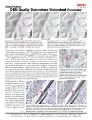
<strong>Tutorial</strong><br />
<strong>Orthorectification</strong> <strong>Using</strong> <strong>Rational</strong> Polynomials<br />
<strong>Orthorectification</strong><br />
<strong>Using</strong><br />
<strong>Rational</strong> Polynomials<br />
with<br />
TNTmips ®<br />
page 1
<strong>Orthorectification</strong> <strong>Using</strong> <strong>Rational</strong> Polynomials<br />
Before Getting Started<br />
You can orthorectify certain types of satellite images that are supplied with a<br />
mathematical model of the image geometry in the form of a set of rational polynomial<br />
coefficients. This procedure also requires a digital elevation model. You can<br />
often improve the fit of the rational polynomial model to a particular image by<br />
regeoreferencing the image using accurate 3D ground control points. This booklet<br />
introduces the concepts and procedures involved in rational polynomial<br />
orthorectification in TNTmips, including the use of the rational polynomial model<br />
in georeferencing the image prior to rectification.<br />
Prerequisite Skills This booklet assumes that you have completed the exercises<br />
in the Displaying Geospatial Data and Navigating tutorial booklets. Those<br />
exercises introduce essential skills and basic techniques that are not covered<br />
again here. You should also be familiar with the topics covered in the<br />
Georeferencing and Rectifying Images tutorial booklets. Please consult those<br />
booklets for any review you need.<br />
Sample Data The exercises in this booklet use sample data that is distributed<br />
with the TNT products. If you do not have access to a TNT products CD, you<br />
can download the data from <strong>MicroImages</strong>’ web site. In particular, this booklet<br />
uses sample files in the RECTIFY directory. Make a read-write copy of the sample<br />
data on your hard drive so changes can be saved when you use these objects.<br />
More Documentation This booklet is intended only as an introduction to<br />
orthorectifying satellite images. Details of the process can be found in a variety<br />
of tutorial booklets, color plates, and Quick Guides, which are all available from<br />
<strong>MicroImages</strong>’ web site.<br />
TNTmips and TNTlite ® TNTmips comes in two versions: the professional version<br />
and the free TNTlite version. This booklet refers to both versions as<br />
“TNTmips.” If you did not purchase the professional version (which requires a<br />
software license key), TNTmips operates in TNTlite mode, which limits object<br />
size and does not allow preparation of linked atlases.<br />
All the exercises can be completed in TNTlite using the sample geodata provided.<br />
Randall B. Smith, Ph.D., 21 May 2008<br />
©<strong>MicroImages</strong>, <strong>Inc</strong>., 2004-2008<br />
It may be difficult to identify the important points in some illustrations without a<br />
color copy of this booklet. You can print or read this booklet in color from<br />
<strong>MicroImages</strong>’ Web site. The Web site is also your source for the newest<br />
<strong>Tutorial</strong> booklets on other topics. You can download an installation guide,<br />
sample data, and the latest version of TNTlite.<br />
http://www.microimages.com<br />
page 2
<strong>Orthorectification</strong> <strong>Using</strong> <strong>Rational</strong> Polynomials<br />
Welcome to RPC <strong>Orthorectification</strong><br />
Aerial and satellite images of land surfaces commonly<br />
contain spatial distortions due to terrain relief and<br />
off-vertical imaging geometry. <strong>Orthorectification</strong> is<br />
a procedure that removes these distortions, creating<br />
an orthoimage with features positioned as they<br />
would be in a planimetric map. Because an<br />
orthoimage has map-like geometry, map-derived thematic<br />
data layers register more accurately with an<br />
orthoimage than with an unrectified image, and the<br />
spatial information you extract from an orthoimage<br />
is more accurate.<br />
You can orthorectify<br />
certain<br />
types of satellite<br />
images in the<br />
TNTmips Automatic<br />
Resampling<br />
process using a<br />
digital elevation<br />
model (DEM) and<br />
the <strong>Rational</strong> Polynomial<br />
resampling<br />
model. IKONOS<br />
Geo Ortho Kit<br />
images (from<br />
Space Imaging<br />
<strong>Inc</strong>.) and QuickBird Ortho Ready Standard Product<br />
images (from DigitalGlobe) are currently the only<br />
types of images that can be orthorectified using this<br />
method. These images are acquired from a high<br />
viewing angle to minimize distortion, and they are<br />
supplied with auxiliary files containing the rational<br />
polynomial coefficients (RPC) required for the<br />
orthorectification.<br />
page 3<br />
STEPS<br />
start TNTmips<br />
select Raster /<br />
Resample and Reproject<br />
/ Automatic... from the<br />
TNTmips menu<br />
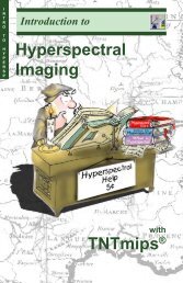
Planimetric street vector (orange, traced from aerial<br />
orthophoto) overlaid on panchromatic IKONOS satellite<br />
image (1-meter cell size) of part of La Jolla, California.<br />
Left, georeferenced but unrectified image. Right, image<br />
after RPC orthorectification, resulting in excellent match<br />
with street vector. Area has about 60 meters of relief.<br />
In the research literature the<br />
acronym RPC is derived<br />
either from “<strong>Rational</strong><br />
Polynomial Coefficients” or<br />
“<strong>Rational</strong> Polynomial Camera<br />
model”. Other authors use<br />
the term <strong>Rational</strong> Function<br />
Model (RFM) to refer to the<br />
same mathematical model.<br />
NOTE: Aerial images acquired with a framing camera (film or digital) have a<br />
simpler imaging geometry than satellite images. Camera images can be<br />
orthorectified in the Photogrammetric Modeling process in TNTmips, either<br />
using a stereo pair of photos or a single photo and a digital elevation model<br />
(see the tutorial booklet Making DEMs and Orthophotos).
<strong>Orthorectification</strong> <strong>Using</strong> <strong>Rational</strong> Polynomials<br />
About <strong>Rational</strong> Polynomial Models<br />
Image<br />
(Unrectified)<br />
<strong>Rational</strong> Polynomial<br />
Coefficients for Image<br />
DEM Raster<br />
+<br />
+<br />
<br />
space<br />
ground<br />
A cross-track scanning<br />
imager such as IKONOS<br />
builds up an image from<br />
groups of scan lines<br />
acquired from different<br />
positions in space (circles)<br />
as the satellite moves<br />
forward in orbit (arrow).<br />
<strong>Rational</strong> Polynomial<br />
<strong>Orthorectification</strong><br />
Orthorectified Image<br />
In a conventional aerial photograph made with a framing<br />
camera, each location in the image is captured at<br />
the same time from a single camera position. Because<br />
of this simple image geometry, the coordinate<br />
transformation from two-dimensional image coordinates<br />
to three-dimensional Earth-surface coordinates<br />
can be expressed mathematically using relatively<br />
simple expressions.<br />
Most remote sensing satellite images, on the other<br />
hand, are built up of groups of scan lines acquired<br />
as the satellite moves forward in its orbit. As a result,<br />
different parts of the same image are acquired<br />
from different sensor positions. In order to rigorously<br />
describe the transformation from image<br />
coordinates to Earth surface coordinates, a mathematical<br />
sensor model that incorporates all of the<br />
physical elements of the imaging system can be exceedingly<br />
long and complex. For example, the<br />
IKONOS rigorous sensor model is 183 pages long!<br />
<strong>Rational</strong> Polynomial satellite sensor models are simpler<br />
empirical mathematical models relating image<br />
space (line and column position) to latitude, longitude,<br />
and surface elevation. The name <strong>Rational</strong><br />
Polynomial derives from the fact that the model is<br />
expressed as the ratio of two cubic polynomial expressions.<br />
Actually, a single image involves two<br />
such rational polynomials, one for computing line<br />
position and one for the column position. The coefficients<br />
of these two rational polynomials are<br />
computed by the satellite company from the<br />
satellite’s orbital position and orientation and the<br />
rigorous physical sensor model. <strong>Using</strong> the<br />
georeferenced satellite image, its rational polynomial<br />
coefficients, and a DEM to supply the elevation<br />
values, the TNTmips Automatic Resampling Process<br />
computes the proper geographic position for each<br />
image cell, producing an orthorectified image.<br />
page 4
<strong>Orthorectification</strong> <strong>Using</strong> <strong>Rational</strong> Polynomials<br />
Acquiring a Digital Elevation Model<br />
The digital elevation model you use to orthorectify<br />
an image need not match the image area or cell size<br />
(the common area of the two is orthorectified). To<br />
achieve the best results, however, the cell size of<br />
the DEM should be as close as possible to that of<br />
the image you are rectifying. DEMs with 30-meter<br />
resolution produced by the United States Geological<br />
Survey (USGS) are available for free download<br />
for any area in the United States, and 10-meter USGS<br />
DEMs are available in many areas. For other countries<br />
elevation data with similar resolution may be<br />
available for purchase from the relevant government<br />
agency. A global elevation model (GTOPO30)<br />
is also available for free download from the USGS;<br />
it has a spatial resolution of 30 arc-seconds, or<br />
about 1 km at the equator. Edited 90-m DEMs produced<br />
by NASA’s Shuttle Radar Topography<br />
Mission (SRTM V2) are also available for all of<br />
Earth’s land areas from the USGS.<br />
If you cannot locate a DEM with sufficient spatial<br />
resolution for your image area, you may be able to<br />
create your own. Topographic contour data is available<br />
for some areas in digital form, or it can be<br />
produced from a scanned topographic map of the<br />
area. The resulting vector contour data can be<br />
surface-fit in the TNTmips Surface Modeling process<br />
to create a DEM. (See the tutorial booklet<br />
entitled Surface Modeling for more information.)<br />
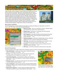
For example, <strong>MicroImages</strong> wished to rectifiy a 1-m<br />
panchromatic IKONOS image of La Jolla, California,<br />
but a 30-m DEM is the best resolution available<br />
from the USGS. Instead we purchased low-cost<br />
vector contour data with 5-foot contour interval<br />
from the County of San Diego. After editing to<br />
remove contouring artifacts, we surface-fit the contours<br />
to create a DEM with 1-meter cell size and<br />
elevation values in decimal meters (floating-point<br />
raster), a resolution more appropriate to our image<br />
data.<br />
page 5<br />
Portion of a 30-m DEM<br />
(displayed with color palette)<br />
for the La Jolla, California<br />
area, the best resolution<br />
available from the USGS.<br />
Portion of DEM with 1-meter<br />
cell size created by surfacefitting<br />
vector contour lines<br />
with a 5-foot contour interval<br />
(black lines).
<strong>Orthorectification</strong> <strong>Using</strong> <strong>Rational</strong> Polynomials<br />
Elevation Units and Reference Surfaces<br />
Topographic contour maps and digital elevation models may express elevation<br />
values in a variety of units. For example, DEMs available for the United States<br />
may have elevations in meters, decimeters, or feet, depending on the data source<br />
and the local relief. Before using a DEM for RPC orthorectification, check the<br />
metadata or other text information that accompanied the original data to verify the<br />
elevation units. The RPC orthorectification procedure requires elevations in meters.<br />
If your DEM uses other elevation units, don’t panic. The simplest remedy is to<br />
open the TNTmips Project File Maintenance<br />
process (Support / Maintenance /<br />
Project File), navigate to the DEM raster,<br />
and press the Edit icon button, which<br />
opens the Edit Object Information window.<br />
The Scale panel on this window<br />
includes a Cell Value Scale field in which<br />
you can enter the conversion factor to<br />
rescale the raster cell values to meters<br />
Edit Object Information window for a<br />
DEM in feet, with Cell Value Scale set to<br />
rescale DEM values to meters.<br />
The rational polynomial coefficients for a particular satellite image are computed<br />
using data on the orbital position and orientation of the satellite sensor. The<br />
satellite position includes a height (elevation) component, but that raises the<br />
question, height above what? The physical surface of the Earth is irregular and<br />
its elevation is not known precisely everywhere, so it cannot be used as a reference<br />
surface. Satellite heights instead are referenced to an ideal, mathematically-defined<br />
geometric shape, an earth-centered ellipsoid, that<br />
provides a global best fit to the overall shape of<br />
the earth. This ellipsoid is most commonly the<br />
World Geodetic System (WGS) 1984 ellipsoid that<br />
forms the basis for the WGS 1984 geodetic datum.<br />
Both remote sensing satellites (such as QuickBird<br />
and IKONOS) and the constellation of Global<br />
Positioning System (GPS) satellites reference<br />
elevations to this hypothetical ellipsoidal surface.<br />
The global best-fit ellipsoid is<br />
nearly spherical, with a polar<br />
radius that is shorter than the<br />
equatorial radius by a factor<br />
of 1 / 298.257.<br />
(for example, 0.1 to rescale decimeters to<br />
meters and 0.3048 to convert feet to<br />
meters). All TNTmips processes will then<br />
automatically use the rescaled value.<br />
Thus the elevation values built into the RPC model<br />
for an image are ellipsoidal elevations, as are the<br />
elevation values computed by GPS receivers from<br />
the GPS satellite information.<br />
page 6
Ellipsoid<br />
Geoid<br />
<strong>Orthorectification</strong> <strong>Using</strong> <strong>Rational</strong> Polynomials<br />
On the other hand, the elevation values in most DEMs give the height of the<br />
ground surface relative to local mean sea level. This value is sometimes called<br />
orthometric height. Mean sea level on a global scale is a broadly undulating<br />
surface called the geoid,whose shape has been determined from studies of the<br />
Earth’s gravity field supplemented by GPS survey data. The vertical separation<br />
between the geoid and el-<br />
Global Geoid Height Relative to the WGS84 Ellipsoid<br />
lipsoid at any location is<br />
180 90 W 0 90 E 180<br />
called the geoid height,<br />
60 N<br />
which may be either positive<br />
(geoid above ellipsoid)<br />
30 N<br />
or negative (geoid below<br />
0<br />
ellipsoid). Geoid heights<br />
30 S<br />
vary gradually on a regional<br />
to continental scale<br />
60 S<br />
within the range -100 to<br />
meters<br />
+100 meters.<br />
Geoid height in vertical section (exaggerated)<br />
Geoid height<br />
(negative)<br />
page 7<br />
-100 -50 0 +50<br />
Geoid height<br />
(positive)<br />
Since rational polynomial image models use ellipsoidal elevations, georeference<br />
and rectification procedures that use this model must convert orthometric DEM<br />
elevations to ellipsoidal heights by subtracting the local geoid height. Therefore,<br />
when you select a DEM in the Georeference or Automatic Resampling processes,<br />
you are prompted to enter a geoid height. (Because of the regional scale of geoid<br />
height variations, a single geoid height value can suffice for an entire IKONOS or<br />
QuickBird scene.) You can find the appropriate geoid height for your image area<br />
by entering the latitude and longitude of the image center in one of several free<br />
geoid height calculators available on the World Wide Web:<br />
http://earth-info.nga.mil/GandG/wgs84/gravitymod/egm96/intpt.html<br />
http://sps.unavco.org/geoid/<br />
Obtaining the Geoid Height<br />
http://www.ngs.noaa.gov/cgi-bin/GEOID_STUFF/geoid03_prompt1.prl<br />
A Windows 9x/NT software program to compute geoid heights is also available<br />
(with supporting files) for free download at:<br />
http://earth-info.nga.mil/GandG/wgs84/gravitymod/egm96/egm96.htm
<strong>Orthorectification</strong> <strong>Using</strong> <strong>Rational</strong> Polynomials<br />
Run the RPC <strong>Orthorectification</strong><br />
STEPS<br />
in the Raster<br />
Resampling window,<br />
press [Select Rasters...]<br />
navigate into the LJMESA<br />
Project File in the RECTIFY<br />
sample data directory<br />
and select IKONLJM4<br />
on the Settings tabbed<br />
panel, set the Model<br />
menu to <strong>Rational</strong><br />
Polynomial<br />
when prompted to<br />
select the <strong>Rational</strong><br />
Polynomial model file,<br />
select RECTIFY /<br />
IKONLJM4_RPC.TXT<br />
when prompted to<br />
select the DEM raster,<br />
select DEM_4M from the<br />
LJMESA Project File<br />
set the Method menu to<br />
Nearest Neighbor and<br />
the Scale menu to By<br />
Cell Size<br />
set the Orient menu to<br />
To Projection and the<br />
Extents menu to Entire<br />
Input<br />
enter -35.0 in the Geoid<br />
height field<br />
press [Run]<br />
use the standard Select<br />
Object window to select<br />
or create a destination<br />
Project File and to name<br />
the output raster object<br />
<strong>Orthorectification</strong> using the <strong>Rational</strong> Polynomial<br />
model is carried out in the Automatic Resampling<br />
process using the <strong>Rational</strong> Polynomial selection on<br />
the Model menu. You can set the model before or<br />
after selecting the raster object (or set of raster objects)<br />
you wish to rectify. When you complete the<br />
second of these two actions, you are presented with<br />
a series of dialogs prompting you to select the elevation<br />
model and to select the text file containing<br />
the rational polynomial coefficients. You must also<br />
provide a value for the local geoid height.<br />
In this exercise you orthorectify a color image created<br />
from the red, green, and blue bands of a sample<br />
IKONOS multispectral image covering part of La<br />
Jolla, California. The image has a cell size of 4 meters<br />
and covers about 4 square kilometers. Topographically,<br />
the area is a plateau sloping southwest, cut by<br />
narrow canyons, and has a local relief of 200 meters.<br />
The image and associated elevation model are shown<br />
on the next page.<br />
You can use the Display process to overlay the original<br />
and orthorectified images to see the geometric<br />
changes produced by the rectification.<br />
page 8
<strong>Orthorectification</strong> <strong>Using</strong> <strong>Rational</strong> Polynomials<br />
Regeoreferencing the Image<br />
The image you rectified in the previous exercise has georeference information<br />
obtained from the image provider. The satellite company determines the<br />
geographic “footprint” of the image using data on the position of the imaging<br />
satellite in its orbit, the direction the sensor was pointing, and an average elevation<br />
for the scene. These parameters are used to compute map coordinates for the<br />
four image corners. But small errors in the satellite parameters can translate into<br />
large errors in the image georeferencing. These errors can cause misregistration<br />
with the DEM you use for rectification, which in turn leads to errors in the position<br />
and internal geometry of the orthorectified image you produce.<br />
You can improve the orthorectification results for most images by regeoreferencing<br />
the image (using the TNTmips Georeference process) with accurate, well-distributed<br />
ground control points (GCPs). This will ensure that accurate geographic<br />
extents are computed for the image and that it registers correctly with the DEM<br />
during orthorectification. (For best results, delete the corner control points provided<br />
with the image.) The new control points should be distributed relatively<br />
uniformly over the entire extent of the image, including the edges and corners.<br />
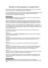
A well-distributed set of ground control points for the IKONOS multispectral image of La<br />
Jolla Mesa (left) covers the image extents and also includes a range of elevations, as<br />
shown in the view of the DEM (right).<br />
The georeference process can also use your control points to refine the rational<br />
polynomial orthorectification model provided with the image (see the following<br />
pages). As few as 4 to 6 accurate, well-distributed points may significantly improve<br />
the fit of the model and thus improve the registration and internal geometry<br />
of the orthorectified image you produce with it. A larger number of control points<br />
may improve the fit in some cases, in part by diluting or averaging out positional<br />
errors introduced by any less accurate control points. Placing additional control<br />
points in topographically significant locations (such as hill tops and valley bottoms)<br />
may further improve the fit of the RPC model.<br />
page 9
<strong>Orthorectification</strong> <strong>Using</strong> <strong>Rational</strong> Polynomials<br />
Georeference with RPC Model<br />
STEPS<br />
choose Main/<br />
Georeference from the<br />
TNTmips menu<br />
in the Object<br />
Georeferencing<br />
window, choose File /<br />
Open<br />
use the standard Select<br />
Objects dialog to select<br />
raster object IKONLJM4G<br />
from the LJMESA Project<br />
File<br />
click [OK] on the Select<br />
Subobject dialog to open<br />
the existing UTM<br />
georeference object<br />
select raster object<br />
DEM_4M from the LJMESA<br />
Project File as the<br />
surface layer<br />
enter -35 in the Prompt<br />
dialog for the local geoid<br />
height and press [OK]<br />
choose Show Elevation<br />
in List from the<br />
Options menu<br />
When you save the georeference information using the<br />
<strong>Rational</strong> Polynomial model, the RPC text information is<br />
automatically saved with the georeference subobject.<br />
If you open such an image in the Georeference<br />
process (as in this exercise) or in the Automatic<br />
Resampling process, the RPCs are read automatically<br />
and the model is set to <strong>Rational</strong> Polynomial. You then<br />
just need to select the DEM and enter the geoid height.<br />
When you regeoreference an image prior to RPC<br />
orthorectification, choose <strong>Rational</strong> Polynomial from<br />
the Model menu on the Georeference window. You<br />
are then prompted to select the RPC text file and<br />
DEM and to enter a geoid height. When you choose<br />
this model, control point residuals are computed by<br />
first projecting all control point positions through<br />
the rational polynomial model to remove terrain displacements,<br />
so that the residuals indicate departures<br />
from the rectification model. The process also makes<br />
adjustments to the transformation between image<br />
and geographic coordinates to minimize these residuals.<br />
This adjustment requires an accurate<br />
elevation value for each control point in addition to<br />
its horizontal coordinates. You can enter elevation<br />
values manually (along with the map coordinates) in<br />
the Reference panel, or use the Set Z from Surface<br />
icon button on the same panel to automatically assign<br />
the elevation value from the corresponding cell<br />
in the DEM.<br />
page 10<br />
The Set Z from Surface<br />
icon button is active when<br />
you are in the process of<br />
adding or editing a<br />
control point.
Control point collected at<br />
a picnic table in a public<br />
park using an inexpensive<br />
hand-held GPS<br />
receiver. If you are<br />
using the GPS fix “Z”<br />
value for your control<br />
point elevation, be sure<br />
to subtract the unit’s<br />
height above the ground.<br />
<strong>Orthorectification</strong> <strong>Using</strong> <strong>Rational</strong> Polynomials<br />
Control Points from GPS Survey<br />
You can use several methods to acquire control points to<br />
regeoreference an image. If you have access to the area, you can<br />
use a Global Positioning System (GPS) receiver to acquire geographic<br />
position data. Since the routine use of Selective<br />
Availability (intentional degradation of position accuracy to nonmilitary<br />
receivers) has been discontinued, even a single<br />
inexpensive handheld GPS unit can determine map coordinates<br />
accurately enough to provide adequate control points for multispectral<br />
(4-meter) IKONOS and QuickBird images. You can achieve<br />
even greater positional accuracy using a receiver designed to<br />
accept real-time differential corrections, either from a<br />
surface broadcast source or from the Wide Area Augmentation<br />
System (WAAS) satellites. Alternatively,<br />
you can use a second stationary GPS unit to collect<br />
data to apply differential correction post-processing<br />
to the data from your roaming receiver.<br />
page 11<br />
Your GPS stations should be<br />
in open areas free of obstructions<br />
that could block the<br />
GPS signal or the differential<br />
correction signal. In addition,<br />
the stations must be easily<br />
recognizable in the image.<br />
GPS positions are normally expressed as latitude and<br />
longitude relative to the WGS 1984 datum. You may<br />
find it convenient to configure your GPS to report<br />
positions in the same coordinate system and datum<br />
used by your image. However, if you don’t, the Setup<br />
/ Projections menu option in the Georeference process<br />
allows you to configure the process to input<br />
coordinates in one coordinate reference system (CRS)<br />
and save them in another CRS. The elevation computed from the GPS satellites is<br />
the ellipsoidal elevation. This value is usually less accurate than the horizontal<br />
coordinates, so you may consider using the DEM elevation instead. In addition,<br />
some GPS receivers incorporate a barometer to report elevations. You typically<br />
calibrate the barometric elevation using a known elevation from a topographic<br />
map, which shows geoidal elevations. So you must subtract the geoid height<br />
from any barometric elevation before entering the elevation for the control point.
<strong>Orthorectification</strong> <strong>Using</strong> <strong>Rational</strong> Polynomials<br />
Control from Maps or Orthoimages<br />
If you cannot travel to the image area or don’t<br />
have access to a GPS, you can use a digital<br />
version of a topographic map, other planimetric<br />
map, or orthoimage of the area to provide<br />
control point locations. In the United States<br />
and some other developed countries,<br />
georeferenced bitmap (raster) images of topographic<br />
maps at various scales are available<br />
from government agencies. If only paper maps<br />
are available to you, you can have them<br />
scanned and then georeference the resulting<br />
map rasters. Digital orthoimages may be available<br />
from federal, state/provincial, or local<br />
government agencies.<br />
When using a scanned map as a reference for<br />
georeferencing, you will need to find features<br />
that are readily recognizable in both the map<br />
and your image, such as road intersections and<br />
stream confluences. The accuracy of your control<br />
point positions on the reference map is more dependent on the spatial accuracy<br />
standard of the original map than on the cell size of the scanned version. A<br />
reference orthoimage typically provides more mutually-recognizable features as<br />
well as more detail and better spatial accuracy.<br />
A topographic map has the advantage of including elevation information in the<br />
form of contour lines. You can compute the elevation for a control point by<br />
interpolating between adjacent contours. Remember that control point elevations<br />
must be ellipsoidal elevations in meters; before assigning your interpolated<br />
elevation to the point in the Georeference process, convert it to meters (if necessary)<br />
and subtract the local geoid height. If your DEM of the image area is<br />
sufficiently detailed, you may<br />
want to assign control point<br />
elevations from the DEM instead.<br />
If you are using an<br />
To use a reference object in the Georeference<br />
process, choose Show 2D Reference View from<br />
the Options menu. Then use the Reference Layer<br />
Controls to add the desired raster object to the<br />
Reference Object View. See the Georeferencing<br />
tutorial booklet for more information.<br />
page 12<br />
orthoimage to georeference<br />
your image, you will need to<br />
acquire control point elevations<br />
from another source<br />
(such as the DEM).
<strong>Orthorectification</strong> <strong>Using</strong> <strong>Rational</strong> Polynomials<br />
Control Point Residuals and Statistics<br />
The column and line positions and residual errors shown in the control point list<br />
in the main Georeference window refer to positions in the input unrectified image.<br />
When you use the <strong>Rational</strong> Polynomial model to compute residuals, a window<br />
entitled Control Points Projected to Orthorectified Image also opens. This window<br />
shows the column and line positions of control points in the orthorectified<br />
image that would be produced from the current adjusted RPC model, along with<br />
the resulting residuals. The residual values for the same point in the two windows<br />
are typically very similar, but not identical.<br />
As noted previously, these residuals show the distance between each control<br />
point and its predicted position in the overall best-fit model computed from the<br />
entire set of points, with terrain displacement effects already accounted for. You<br />
can use the Options menu on the main Georeference window to elect to show<br />
separate or combined X-Y residuals. (Z-residuals in both windows simply show<br />
the difference between the entered value and the DEM value at that position; if<br />
you assign control point elevations from the DEM, the Z-residual will be 0 for<br />
such points). You can turn on the Edit radio button to adjust the positions of<br />
control points that appear poorly placed as indicated by high residual values (see<br />
next page).<br />
The bottom part of each of these Georeference windows shows summary statistics<br />
for the current set of control points. The RMS (Root Mean Square) Error and<br />
Mean Deviation values provide measures of the fit of the entire set of control<br />
points to the adjusted rational polynomial model. These values are updated<br />
immediately with any change in the control points.<br />
page 13<br />
Summary<br />
statistics for<br />
the main<br />
Georeference<br />
window.
<strong>Orthorectification</strong> <strong>Using</strong> <strong>Rational</strong> Polynomials<br />
Evaluating Control Points<br />
You can use the individual control point residuals and the RMS error statistics<br />
shown in the Georeference windows to help judge the accuracy of your control<br />
points. However, this is a subjective procedure, and there are no rigid guidelines.<br />
Ideally, you would like the point residuals to be less than the cell size of the image,<br />
but you may only be able to approximate this level of accuracy. A large error<br />
residual for a particular point may indicate that you made a blunder of some sort.<br />
You may have incorrectly recorded a GPS map coordinate in the field, mistyped a<br />
value when entering point coordinates, or placed the point in the wrong location<br />
in the Input or Reference view. If you can’t identify an obvious source of error or<br />
don’t have the information to correct it, you can toggle off the checkbox to the left<br />
of the point’s entry in the list to make the anomalous point Inactive. The residuals<br />
for the remaining active points (and the overall RMS error for the active points)<br />
are automatically recalculated. If you find there is dramatic improvement, you<br />
may want to delete the anomalous point.<br />
To inactivate a control<br />
point, left-click on the<br />
checkbox to the left of<br />
its entry in the list to<br />
uncheck it. List<br />
colors for the active,<br />
inactive, and current<br />
selected point are<br />
subdued versions of<br />
the symbol colors set<br />
using the Options /<br />
Colors menu option. In<br />
this example, active<br />
points are yellow,<br />
inactive points are<br />
green, and the<br />
selected point is red.<br />
However, remember that residuals are computed from a global best fit to the entire<br />
set of active points. All points contribute equally to this procedure, so the result<br />
is influenced by the distribution of points. A control point may have a high<br />
residual error because it is isolated from other points that are more clustered<br />
together, and you usually need to retain such isolated points to provide adequate<br />
coverage of the image. Don’t assume that the point with the highest residual is<br />
necessarily the “worst point” in the set. And residuals do not reveal systematic<br />
error that may affect all points equally, such as choosing the wrong datum.<br />
page 14
<strong>Orthorectification</strong> <strong>Using</strong> <strong>Rational</strong> Polynomials<br />
page 15<br />
<strong>Using</strong> Test Points<br />
If you have a sufficient number of control points that you believe are accurate,<br />
you can reserve some of them to use as test points to check the quality of your<br />
control point set. First enter just the control points, check the residuals, and edit<br />
or delete any problem points. Then enter the test points and set each of them to<br />
be inactive. Residuals and overall RMS errors are computed separately for the<br />
active and inactive points, so they represent independent applications of the<br />
current RPC model. Since your “test” points were not used to develop the active<br />
point model, they represent an independent test of the accuracy of your control<br />
points. If the RMS error and individual point residuals for your test points are<br />
small (comparable in size to those for the active points), then you probably have<br />
a suitably accurate set of control points to perform the RPC orthorectification.<br />
Currently the status of control points (active or<br />
inactive) is temporary, applicable only to the<br />
current Georeference session; it is not saved<br />
with the georeference information. In fact the<br />
default option (on the Options menu on the<br />
Georeference window) is not to save inactive<br />
control points at all. Keep this behavior in mind if<br />
you use test points to check your georeference.<br />
In this example, GPS<br />
control points for the 1meter<br />
image below<br />
(yellow) are supplemented<br />
with inactive test<br />
points (green) placed<br />
from orthophotos with<br />
0.15 meter resolution.<br />
The overall XY RMS error<br />
for the test points is<br />
comparable to (even less<br />
than) the error for the<br />
control points, indicating<br />
an accurate set of<br />
control points.<br />
To see the effects of regeoreferencing the image,<br />
run the RPC orthorectification again<br />
(steps on page 8) using the regeoreferenced<br />
sample image (IKONLJM4G). You can overlay the two orthoimages in the Display<br />
process to see the geometric changes that result.
<strong>Orthorectification</strong> Advanced <strong>Using</strong> Software <strong>Rational</strong> Polynomials for Geospatial Analysis<br />
<strong>MicroImages</strong>, <strong>Inc</strong>. publishes a complete line of professional software for advanced geospatial<br />
data visualization, analysis, and publishing. Contact us or visit our web site for detailed product<br />
information.<br />
TNTmips TNTmips is a professional system for fully integrated GIS, image analysis, CAD,<br />
TIN, desktop cartography, and geospatial database management.<br />
TNTedit TNTedit provides interactive tools to create, georeference, and edit vector, image,<br />
CAD, TIN, and relational database project materials in a wide variety of formats.<br />
TNTview TNTview has the same powerful display features as TNTmips and is perfect for<br />
those who do not need the technical processing and preparation features of TNTmips.<br />
TNTatlas TNTatlas lets you publish and distribute your spatial project materials on CD-<br />
ROM at low cost. TNTatlas CDs can be used on any popular computing platform.<br />
TNTserver TNTserver lets you publish TNTatlases on the Internet or on your intranet.<br />
Navigate through geodata atlases with your web browser and the TNTclient Java applet.<br />
TNTlite TNTlite is a free version of TNTmips for students and professionals with small<br />
projects. You can download TNTlite from <strong>MicroImages</strong>’ web site, or you can order<br />
TNTlite on CD-ROM.<br />
barometric elevation...............................11<br />
contours..............................................5,12<br />
digital elevation model (DEM)............3-13<br />
ellipsoid...................................................6<br />
ellipsoidal elevation...........................6,7,12<br />
geoid........................................................7<br />
geoid height................................7,8,10-12<br />
georeference........................................9-15<br />
Global Positioning System (GPS)...............7<br />
IKONOS.....................................3,4,5,8,11<br />
Index<br />
orthometric height...................................7<br />
orthorectification.................3,4,5,8,9,10,13,15<br />
QuickBird............................................3,11<br />
rational polynomial.................3,4,7-10,13<br />
residuals.......................................10,13-15<br />
Root Mean Square (RMS) error.........13-15<br />
Set Z from Surface.................................10<br />
topographic map...................................12<br />
Wide Area Augmentation System.............11<br />
<strong>MicroImages</strong>, <strong>Inc</strong>.<br />
11th Floor - Sharp Tower<br />
206 South 13th Street<br />
Lincoln, Nebraska 68508-2010 USA<br />
Voice: (402) 477-9554 email: info@microimages.com<br />
page 16<br />
FAX: (402) 477-9559 internet: www.microimages.com<br />
R<br />
P<br />
C<br />
O<br />
R<br />
T<br />
H<br />
O