CBM Progress Report 2006 - GSI
CBM Progress Report 2006 - GSI
CBM Progress Report 2006 - GSI

You also want an ePaper? Increase the reach of your titles
YUMPU automatically turns print PDFs into web optimized ePapers that Google loves.
<strong>CBM</strong> <strong>Progress</strong> <strong>Report</strong><br />
<strong>2006</strong><br />
1
Preface<br />
In <strong>2006</strong> the <strong>CBM</strong> project has made important steps towards realisation. This includes<br />
progress in the design and development of simulation software, detector components,<br />
front-end electronics, and concepts for data acquisition.<br />
The continuous improvements of the software framework (<strong>CBM</strong>root) and of the event<br />
reconstruction algorithms permitted to optimize the layout of the Silicon Tracking System<br />
(STS). Track reconstruction based on a realistic STS design is now routinely used in the<br />
feasibility studies for open charm measurements, for the identification of hadrons<br />
(including multi-strange hyperons), and for the reconstruction of vector mesons via their<br />
dileptonic decays. The identification of electrons is based now on the realistic response<br />
of the Ring Imaging Cherenkov (RICH) detector using ring recognition algorithms, and<br />
on the analysis of the energy loss signals in the Transition Radiation Detector (TRD).<br />
For muon identification a compact absorber/detector system has been developed with<br />
promising performance. Full track reconstruction is available for particle identification<br />
taking into account the hits in the STS, in the 12 TRD layers, and in the timing Resistive<br />
Plate Chamber (RPC) wall.<br />
Hardware R&D concentrated on the design, construction and test of various prototype<br />
detectors: radiation tolerant Monolithic Active Pixel Sensors, thin double-sided Silicon<br />
Microstrip sensors, TRDs with high rate capability, high-rate timing RPCs, and modules<br />
for the Projectile Spectator Detector. Concerning the development of front-end<br />
electronics we made a big step forward with the first prototype of a self-triggered fast<br />
readout chip for Silicon Strip and GEM detectors which is available now and being<br />
tested. Moreover, building blocks for the front-end electronics of TRD and RPC have<br />
been designed. Last but not least the framework of a future data acquisition system is<br />
under development.<br />
The status of the ongoing <strong>CBM</strong> activities is documented in this <strong>Report</strong>. There is also<br />
progress in the development of the collaboration: six groups from Indian universities and<br />
institutes have joined <strong>CBM</strong> in <strong>2006</strong>. They will concentrate on the development of the<br />
muon detection system. Beyond the efforts devoted to the design and construction of<br />
the experimental setup there is ongoing work – mainly by many colleagues from theory -<br />
to write-up the <strong>CBM</strong> Physics Book. The first draft of the book has been completed and is<br />
being discussed within the theory working groups.<br />
Many thanks to the colleagues who have contributed to this report.<br />
February 2007 Peter Senger<br />
i
Contents<br />
Preface i<br />
Overview 1<br />
Simulations 3<br />
FairRoot/CbmRoot Simulation and Analysis framework (M. Al-Turany et al.) . . . . . . . . . . . . . . . 3<br />
Event Reconstruction in the <strong>CBM</strong> Experiment (I. Kisel et al.) . . . . . . . . . . . . . . . . . . . . . . . . . 4<br />
Track reconstruction in the <strong>CBM</strong>-STS (O. Rogachevsky and A. Jerusalimov) . . . . . . . . . . . . . . . . . 5<br />
Implementation of a Hough Tracker for <strong>CBM</strong> (C. Steinle et al.) . . . . . . . . . . . . . . . . . . . . . . . . 6<br />
Global tracking and hadron identification in the <strong>CBM</strong> experiment (D. Kresan and V. Frise) . . . . . . . 7<br />
Tracking in the TRD (A. Lebedev and G. Ososkov) . . . . . . . . . . . . . . . . . . . . . . . . . . . . . . . . 8<br />
Standalone TRD tracking using the Cellular Automaton Algorithm (A. Bubak et al.) . . . . . . . . . . . 9<br />
Ring recognition in the RICH detector of <strong>CBM</strong> (S. Lebedev et al.) . . . . . . . . . . . . . . . . . . . . . . 10<br />
Application of the Omega test for J/Psi detection in the <strong>CBM</strong> experiment (E.P. Akishina et al.) . . . . . . 11<br />
Electron/pion identification in the <strong>CBM</strong> TRD using a multilayer perceptron (E.P. Akishina et al.) . . . . 12<br />
Electron identification with RICH and TRD in <strong>CBM</strong> (C. Hoehne et al.) . . . . . . . . . . . . . . . . . . . 13<br />
Feasibility of hyperon detection in the <strong>CBM</strong> experiment (E. Kryshen et al.) . . . . . . . . . . . . . . . . . 14<br />
Open charm measurement in the <strong>CBM</strong> experiment (I. Vassiliev et al.) . . . . . . . . . . . . . . . . . . . . 15<br />
Full reconstruction of low-mass electron pairs in <strong>CBM</strong> (T. Galatyuk et al.) . . . . . . . . . . . . . . . . . 16<br />
Fast simulation of low-mass electron pair measurements with <strong>CBM</strong> (P. Staszel et al.) . . . . . . . . . . . 17<br />
J/Psi detection via electron-positron decay in <strong>CBM</strong> (A. Maevskaya et al.) . . . . . . . . . . . . . . . . . . 18<br />
Vector meson detection via mu+ - mu- decays in <strong>CBM</strong> (A. Kiseleva at al.) . . . . . . . . . . . . . . . . . 19<br />
Study of J/Psi measurements with distant detector arms (K. Piaseki et al.) . . . . . . . . . . . . . . . . . 20<br />
Measurement of pion interaction in a lead absorber (S. Chattopadhyay) . . . . . . . . . . . . . . . . . . . 21<br />
Feasibility studies for a muon detection system (S. Chattopadhyay) . . . . . . . . . . . . . . . . . . . . . 22<br />
Muon detector simulations and choice of the RICH mirror shape (V. Baublis et al.) . . . . . . . . . . . . 23<br />
HERA-B Dipole Magnet simulations for <strong>CBM</strong> (P. Akishin et al.) . . . . . . . . . . . . . . . . . . . . . . . 24<br />
HADES@SIS100 (A. Kugler et al.) . . . . . . . . . . . . . . . . . . . . . . . . . . . . . . . . . . . . . . . . 25<br />
Dielectron Detection Capabilities of HADES for Beam Energies accessible at FAIR (B. Bannier et al.) . . 26<br />
Detector Developments 27<br />
Results on timing properties of SCCVD diamond detectors for MIPs (M. Petrovici et al.) . . . . . . . . . 27<br />
Achievements of CMOS Pixel Sensors for the <strong>CBM</strong> Micro-Vertex Detector (A. Amar-Youcef et al.) . . . 28<br />
Layout studies of the <strong>CBM</strong> Silicon Tracking System (J.M. Heuser et al.) . . . . . . . . . . . . . . . . . . . 29<br />
Development of Microstrip Sensors for the <strong>CBM</strong> Silicon Tracking System (J.M. Heuser et al.) . . . . . . 30<br />
Silicon Microstrip Sensor Prototypes for <strong>CBM</strong> (M. Merkin et al.) . . . . . . . . . . . . . . . . . . . . . . . 31<br />
Prototype of the small diameter PMT for the RICH photo-detector plane (V. Brekhovskikh et al.) . . . . 32<br />
Test of Transition Radiation Detectors for high rate environments (C. Garabatos) . . . . . . . . . . . . . 33<br />
Research and Development of fast TRD readout chambers (A. Andronic et al.) . . . . . . . . . . . . . . 34<br />
Electron/pion identification with fast TRD prototypes (A. Andronic et al.) . . . . . . . . . . . . . . . . . 35<br />
High efficiency Transition Radiation Detectors for high counting rate environments (M. Petrovici et al.) 37<br />
Development of straw tubes for high rate capability application (K. Davkov et al.) . . . . . . . . . . . . 38<br />
<strong>Progress</strong> in the <strong>CBM</strong>-TOF wall, R&D and simulations (D. Gonzalez-Diaz et al.) . . . . . . . . . . . . . . 39<br />
Ceramic high-rate timing RPCs (L. Lopez et al.) . . . . . . . . . . . . . . . . . . . . . . . . . . . . . . . . 40<br />
Testing the Performance of Timing MRPC Detectors at ELBE (F. Dohrmann et al.) . . . . . . . . . . . . . 41<br />
ii
High Counting Rate Position Sensitive Resistive Plate Counters (M. Petrovici et al.) . . . . . . . . . . . 43<br />
Prototype of the fine-sampling electromagnetic calorimeter (G. Britvich et al.) . . . . . . . . . . . . . . . 45<br />
Simulation studies of calorimeter system. Preshower prototype (S. Belogurov et al.) . . . . . . . . . . . 46<br />
High resolution Projectile Spectator Detector (F. Guber et al.) . . . . . . . . . . . . . . . . . . . . . . . . 48<br />
FEE and DAQ 49<br />
Towards high count rate, data driven Silicon strip readout electronics for <strong>CBM</strong> and other FAIR<br />
experiments (C.J. Schmidt et al.) . . . . . . . . . . . . . . . . . . . . . . . . . . . . . . . . . . . . . . 49<br />
Development of a test system for n-XYTER ASICs (A. Czermak and P. Kusmierski) . . . . . . . . . . . . . 50<br />
Front End Electronic Building Blocks for <strong>CBM</strong> (T. Armbruster et al.) . . . . . . . . . . . . . . . . . . . . 51<br />
Development of building blocks for data driven architecture for the <strong>CBM</strong> microstrip detectors (E. Atkin<br />
et al.) . . . . . . . . . . . . . . . . . . . . . . . . . . . . . . . . . . . . . . . . . . . . . . . . . . . . . 52<br />
An ASIC based fast Preamplifier-Discriminator (PADI) for MRPCs (M. Ciobanu et al.) . . . . . . . . . . 53<br />
PCI Express DMA Engine Design (W. Gao et al.) . . . . . . . . . . . . . . . . . . . . . . . . . . . . . . . . 54<br />
Developments for a future DAQ framework DABC (J. Adamczewski et al.) . . . . . . . . . . . . . . . . . 55<br />
Infiniband cluster for Future DAQ (J. Adamczewski et al.) . . . . . . . . . . . . . . . . . . . . . . . . . . . 56<br />
Appendices 57<br />
Workshops and Meetings <strong>2006</strong> . . . . . . . . . . . . . . . . . . . . . . . . . . . . . . . . . . . . . . . . . 57<br />
Publications <strong>2006</strong> . . . . . . . . . . . . . . . . . . . . . . . . . . . . . . . . . . . . . . . . . . . . . . . . . 57<br />
<strong>CBM</strong> Notes <strong>2006</strong> . . . . . . . . . . . . . . . . . . . . . . . . . . . . . . . . . . . . . . . . . . . . . . . . . . 57<br />
List of Institutions . . . . . . . . . . . . . . . . . . . . . . . . . . . . . . . . . . . . . . . . . . . . . . . . . 58<br />
Contacts . . . . . . . . . . . . . . . . . . . . . . . . . . . . . . . . . . . . . . . . . . . . . . . . . . . . . . 59<br />
iii
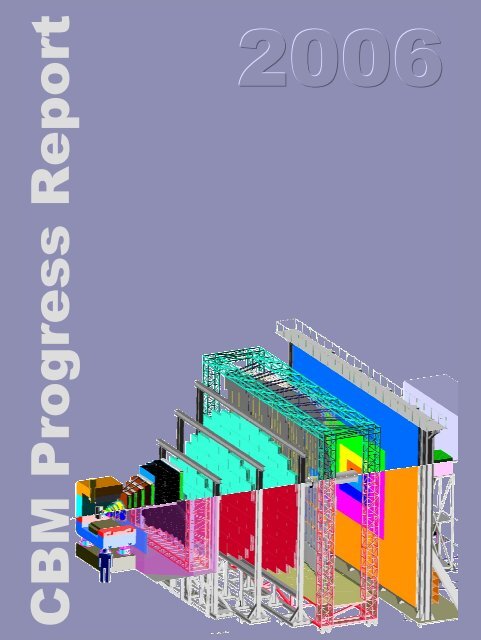
<strong>CBM</strong> <strong>Progress</strong> <strong>Report</strong> <strong>2006</strong> Overview<br />
<strong>CBM</strong> physics and detector setup<br />
The planned Compressed Baryonic Matter (<strong>CBM</strong>) experiment<br />
at FAIR offers unique possibilities to investigate<br />
baryonic matter at highest densities in the laboratory.<br />
The most promising observables from nucleus-nucleus collisions<br />
in the FAIR energy range are particles containing<br />
charm quarks (D-mesons and charmonium), low-mass<br />
vector mesons decaying into dilepton pairs (ρ, ω and φ<br />
mesons), and hyperons (Λ, Ξ, Ω and their antiparticles).<br />
This includes the measurement of (event-by-event) fluctuations,<br />
correlations, and collective flow of hadrons. A<br />
systematic and comprehensive investigation of these observables,<br />
in particular their excitation functions, will permit<br />
to extract information on the equation-of-state of baryonic<br />
matter at high densities, on the location of the phase<br />
boundary between hadronic and partonic matter (including<br />
the QCD critical endpoint), and on the restoration of chiral<br />
symmetry at high net-baryon densities.<br />
The experimental task is to identify hadrons and leptons<br />
in collisions with up to 1000 charged particles at event rates<br />
of up to 10 MHz. A particular experimental challenge is the<br />
identification of D-mesons which is based on the selection<br />
of secondary vertices with high accuracy. The measurements<br />
require a high-speed data acquisition (DAQ) architecture<br />
and an appropriate high-level event-selection concept.<br />
A schematic view of the proposed <strong>CBM</strong> detector concept<br />
is shown in figure 1. Inside a large aperture dipole magnet<br />
there is a Silicon Tracking and Vertexing System which<br />
consists of two parts: a Micro-Vertex Detector (MVD, 2<br />
silicon pixel layers) and the Silicon Tracking System (STS,<br />
several layers of silicon microstrip detectors). The Silicon<br />
detector array has to provide the capabilities for track reconstruction,<br />
determination of primary and secondary vertices,<br />
and momentum determination. Electrons from lowmass<br />
vector-meson decays will be identified with a Ring<br />
Imaging Cherenkov (RICH) detector. The TRD detector<br />
will provide charged particle tracking and the identification<br />
of high energy electrons and positrons. The ECAL will be<br />
used for the identification of electrons and photons. As an<br />
alternative to the RICH detector a muon detection/hadron<br />
absorber system is under investigation. If the RICH will<br />
be replaced by a muon detector the TRD will be converted<br />
into a tracking detector for hadron measurements together<br />
with the timing RPC. Then the TOF-RPC detector serves<br />
for two purposes: for background suppression during muon<br />
measurements with absorbers, and for hadron identification<br />
with muon absorbers removed.<br />
The <strong>CBM</strong> experiment at FAIR<br />
V. Friese, W.F.J. Müller, P. Senger, <strong>GSI</strong> Darmstadt<br />
1<br />
Figure 1: Schematic view of the Compressed Baryonic Matter<br />
(<strong>CBM</strong>) experiment planned at FAIR. The setup consists of a<br />
high resolution Silicon Tracking System (STS), a Ring Imaging<br />
Cherenkov detector (RICH), three stations of Transition Radiation<br />
Detectors (TRD), a time-of-flight (TOF) system made of Resistive<br />
Plate Chambers (RPC) and an Electromagnetic Calorimeter<br />
(ECAL).<br />
Track reconstruction and STS development<br />
The feasibility studies were performed within the <strong>CBM</strong><br />
software framework which has been developed further. The<br />
routines for track and vertex reconstruction have been improved<br />
and used for optimization of the layout of the Silicon<br />
Tracking System. Track reconstruction efficiencies of<br />
above 95% can be obtained with a fast and radiation-hard<br />
detector system which consists either of two Silicon hybrid<br />
pixel detector stations together with 4 double-sided Silicon<br />
Strip detector layers, or of 6 Strip-sensor layers only.<br />
The STS can be used as a stand-alone tracker for high-rate<br />
measurements and for the identification of hyperons. The<br />
Micro-Vertex Detector (MVD) - which is close to the target<br />
and has limitations in radiation hardness and read-out<br />
speed - will be installed only for open charm measurements<br />
which requires high-precision vertexing.<br />
Detector R&D concentrates on the design of a prototype<br />
STS which includes double-sided sensors, the low-mass<br />
micro-cables, the read-out chip and the mechanical structure.<br />
First prototype sensors have been designed and are<br />
being fabricated. Moreover, a fast self-triggered read-out<br />
chip has been developed within EU FP-6 NMI3 for neutron<br />
applications. It was fabricated and is under tests in<br />
cooperation with <strong>CBM</strong>, where it will serve as a prototype<br />
for the <strong>CBM</strong>-dedicated front-end development and addi-
Overview <strong>CBM</strong> <strong>Progress</strong> <strong>Report</strong> <strong>2006</strong><br />
tionally for current detector prototyping R&D efforts.<br />
Hadron identification via TOF<br />
Hadron identification in the <strong>CBM</strong> experiment is performed<br />
using the time-of-flight measurement in the RPC<br />
detector wall located about 10 m downstream of the target.<br />
This requires track reconstruction and momentum determination<br />
in the Silicon Tracking System, track following<br />
through the TRD stations, and matching of reconstructed<br />
tracks to the hits in the RPCs. The total reconstruction efficiency<br />
for hadrons (STS-TRD-RPC) is well above 80 %.<br />
This result is based on realistic detector layouts and performances.<br />
The R&D on prototype timing RPCs concentrates<br />
on high rate capability, low resistivity material, long term<br />
stability and the realization of large arrays with overall excellent<br />
timing performance.<br />
D meson identification and vertex detector<br />
D mesons will be identified via their hadronic decay into<br />
one or two charged pions and a kaon. In order to suppress<br />
the overwhelming combinatorial background of promptly<br />
emitted pions and kaons one has to determine the D meson<br />
decay vertex with an accuracy of about 50 µm (τ(D 0 ) =<br />
123 µm/c, τ(D ± ) = 312 µm/c). This measurement requires<br />
an extremely thin and highly granulated pixel detector. We<br />
are developing a Micro-Vertex Detector (MVD) consisting<br />
of two layers of Monolithic Active Pixel Sensors (MAPS)<br />
with a pixel size between 25x25 µm 2 and 40x40 µm 2 and<br />
a thickness of 100 µm. Both vertex resolution and radiation<br />
damage increase with decreasing distance from the<br />
target. Simulations have been performed in order to optimize<br />
signal-to-background, efficiency, distance and detector<br />
lifetime. According to these studies it is possible to<br />
record 3.6 × 10 5 D mesons in 10 12 minimum bias Au+Au<br />
collisions at 25 AGeV within the lifetime of a MAPS. With<br />
a collision rate of 100 kHz the first MAPS station would<br />
have to be replaced after 120 days of running. The R&D<br />
on the MVD concentrates on the improvement of radiation<br />
hardness and readout speed of the MAPS, and on system<br />
integration.<br />
Electron identification with RICH and TRD<br />
Electrons and positrons are identified with the RICH detector<br />
and with the TRD. The simulations include track reconstruction<br />
in STS and TRD, ring recognition in the RICH<br />
photon detector, ring-track matching, and the analysis of<br />
the energy loss signal in the TRD. With information only<br />
from RICH the pions can be suppressed by a factor of about<br />
500 up to a momentum of about 9 GeV/c. Taking into account<br />
additional information from the TRD the total pion<br />
suppression factor is larger than 10 4 for momenta above 1<br />
GeV/c in central Au+Au collisions at 25 AGeV. This value<br />
will be sufficient to discard misidentified pions from the<br />
combinatorial electron background in vector-meson measurements.<br />
2<br />
The major challenge in the identification of low-mass<br />
vector mesons via their di-electronic decay is to reject the<br />
physical background of electron-positron pairs from Dalitz<br />
decays and gamma conversion. The background rejection<br />
strategies are based on electron identification by RICH and<br />
TRD, and use an improved track reconstruction method for<br />
low momentum particles. The omega meson, for example,<br />
can be measured in central Au+Au collisions at 25 AGeV<br />
with a signal-to-background ratio of 0.2 and an efficiency<br />
of 8%. In the mass range of the J/ψ meson the combinatorial<br />
background can be dramatically reduced by the requirement<br />
of a high transverse momentum of the electrons. For<br />
example, when requiring electron transverse momenta of<br />
pt ≥ 1.2 GeV/c for central Au+Au collisions at 15 (25, 35)<br />
AGeV, signal-to-background ratios of S/B = 0.8 (1.7, 14.5)<br />
and efficiencies of ɛ = 0.09 (0.12, 0.14) can be achieved<br />
for J/ψ mesons. TRD R&D is focused on the improvement<br />
of the electron identification performance, and on the<br />
development of highly granular and fast gaseous detectors<br />
which can stand the high-rate environment of <strong>CBM</strong>. Prototype<br />
gas detectors (based on MWPC and GEM technology)<br />
have been built and tested with particle rates of up to 400<br />
kHz/cm 2 without deterioration of performance.<br />
Muon measurements with hadron absorbers<br />
As an alternative approach to the dielectron measurement<br />
we have studied the possibility of detecting vector<br />
mesons (ρ, ω, φ, J/ψ) via their decay into µ − µ + pairs.<br />
The idea is to suppress the hadrons with several iron absorber<br />
layers located behind the Silicon Tracking System.<br />
In order to match the muons which pass the absorber to the<br />
tracks measured by the Silicon tracker (which defines the<br />
momentum) one has to track all charged particles through<br />
the absorber. This is done by highly granulated and fast detectors<br />
which are located in each gap between the absorber<br />
layers.<br />
The simulations are based on track reconstruction algorithms<br />
taking into account a realistic response of the STS.<br />
The high track density requires a position resolution in the<br />
order of σ = 100-300 µm for the first muon chambers. The<br />
studies demonstrate that for example the ω meson can be<br />
measured in central Au+Au collisions at 15 (25, 35) AGeV<br />
with a signal-to-background ratio of S/B = 0.4 and with an<br />
efficiency of ɛ = 0.01 (0.013, 0.015). J/ψ mesons can be<br />
identified with a signal-to-background ratio of about 100<br />
and an efficiency of ɛ = 0.19 for central Au+Au collisions<br />
at 25 AGeV. Such a number would be sufficient for the<br />
identification of ψ’ mesons in Au+Au collisions. For the<br />
charmonium experiments the total thickness of the hadron<br />
absorber has to be increased as compared to measurements<br />
of low-mass vector mesons.<br />
The challenge for the muon chambers and for the track<br />
reconstruction algorithms is the huge particle density of up<br />
to 1 hit/cm 2 per event in the first detector layers. Therefore,<br />
detector R&D concentrates on the design of fast and highly<br />
granulated gaseous detectors based on GEM technology.
<strong>CBM</strong> <strong>Progress</strong> <strong>Report</strong> <strong>2006</strong> Simulations<br />
FairRoot/CbmRoot Simulation and Analysis framework<br />
M. Al-Turany, D. Bertini, M. Dahlinger, V. Friese, I. Koenig, and F. Uhlig<br />
Introduction<br />
The Virtual Monte Carlo concept allows performing simulations<br />
using Geant3, Geant4 or Fluka without changing<br />
the user code [1]. This concept was used as a base for developing<br />
the CbmRoot framework for the <strong>CBM</strong> collaboration<br />
[2]. In this concept, the same framework is used<br />
for simulation and data analysis. An oracle database with<br />
a build-in versioning management is available and can be<br />
used to efficiently store the detector geometry, materials<br />
and parameters.<br />
As more experiments at the <strong>GSI</strong> where interested in using<br />
this framework, the framework was revised and the<br />
base packages of the framework where completely separated<br />
from the specific <strong>CBM</strong> implementation. Moreover,<br />
the framework got the new name FAIRROOT. On the Oracle<br />
server side, data bases for each experiment are running<br />
on a high availability cluster, new experiments can easily<br />
be added.<br />
The Schematic design of the framework is shown in<br />
Fig.[1].<br />
<br />
<br />
<br />
<br />
<br />
ROOT<br />
<br />
<br />
EVGEN<br />
Virtual MC<br />
Run Manager<br />
Tasks<br />
Field<br />
Geant3<br />
Geant4<br />
FLUKA<br />
IO Manager<br />
RunTime<br />
DataBase<br />
<br />
Figure 1: Schematic design of FairRoot.<br />
• Geane Interface:<br />
New Developments<br />
The Geane package allows the user to calculate the<br />
average trajectories of particles and to calculate the<br />
transport matrix as well as the propagated error covariance<br />
matrix. Geane is a set of routines worked out<br />
by the European Muon Collaboration [3, 4] and it is<br />
integrated to the GEANT3 system [5]. An interface<br />
for using Geane was developed in collaboration with<br />
the Pavia group from the PANDA collaboration. The<br />
<strong>GSI</strong>, Darmstadt, Germany<br />
3<br />
modification to the VMC classes needed for Geane<br />
where also communicated to the ALICE collaboration<br />
at CERN and included in the VMC distribution.<br />
• New detector geometry reader<br />
A new geometry reader for the framework was developed.<br />
The input of this reader is in form of TGeoVolumes<br />
(Root Geometry format). This reader is used by<br />
the PANDA collaboration to read the detector geometries<br />
which are converted from Step file format (CAD<br />
system) to Root format.<br />
• CMake for configuration<br />
CMake is a cross-platform, open-source make system<br />
[6]. CMake is used to control the software compilation<br />
process using simple platform and compiler independent<br />
configuration files. CMake generates native<br />
makefiles and workspaces that can be used in the<br />
compiler environment of user choice. Now CMake<br />
and autoconf/automake are used in parallel.<br />
• Subversion<br />
The frame work is now distributed via Subversion.<br />
Summary<br />
A VMC based framework for <strong>CBM</strong> has been implemented,<br />
the first release was in March 2004. The October<br />
2004 release was used to produce and analyze data for the<br />
<strong>CBM</strong> technical status report[7]. Work on digitizers and full<br />
tracking in <strong>CBM</strong> and PANDA collaborations is going on.<br />
[1] http://alisoft.cern.ch/<br />
References<br />
[2] M.Al-Turany, D. Bertini and I. Koenig , “<strong>CBM</strong> Simulation<br />
and Analyis Framework”, <strong>GSI</strong> scintific report 2004, FAIR-<br />
EXP-07.<br />
[3] W.Wittek, EMC Internal <strong>Report</strong>s: (EMC/80/15, EM-<br />
CSW/80/39, EMCSW/81/13, EMCSW/81/18)<br />
[4] A.Haas, The EMC Utility Package: (UTIL42)<br />
[5] R.Brun, F.Bruyant, M.Maire, A.C.McPherson, P.Zanarini<br />
(DD/EE/84-1), May 1986<br />
[6] http://www.cmake.org/<br />
[7] <strong>CBM</strong> Collaboration Technical Status <strong>Report</strong> (<strong>GSI</strong>, Darmstadt,<br />
2005)
Simulations <strong>CBM</strong> <strong>Progress</strong> <strong>Report</strong> <strong>2006</strong><br />
Event Reconstruction in the <strong>CBM</strong> Experiment<br />
I. Kisel 1,2 , S. Gorbunov 1,3 , J. Heuser 3 , V. Lindenstruth 1 , and Iou. Vassiliev 3<br />
1 KIP, Ruprecht-Karls University, Heidelberg, Germany; 2 LIT, Joint Institute for Nuclear Research, Dubna, Russia;<br />
3 <strong>GSI</strong>, Darmstadt, Germany<br />
A track reconstruction procedure [1, 2, 3] has been improved<br />
and used for optimization of the layout of the Silicon<br />
Tracking System. Fig. 1 shows dependency of the efficiency<br />
of track reconstruction versus momentum in STS<br />
with 2 MAPS stations and 10 double-sided strip stations,<br />
which are grouped into pairs with 1 cm internal distance<br />
(geometry with doubled strip stations).<br />
All Set Efficiency, %<br />
100<br />
90<br />
80<br />
70<br />
60<br />
50<br />
40<br />
30<br />
20<br />
10<br />
0<br />
0 0.5 1 1.5 2 2.5 3 3.5 4 4.5 5<br />
Momentum, GeV/c<br />
Figure 1: Efficiency of the Cellular Automaton track finder<br />
in STS with doubled strip stations.<br />
Momentum resolution, %<br />
3<br />
2.5<br />
2<br />
1.5<br />
1<br />
0.5<br />
0<br />
0 0.5 1 1.5 2 2.5 3 3.5 4 4.5 5<br />
Momentum, GeV/c<br />
Figure 2: Momentum resolution for the standard STS geometry.<br />
Momentum resolution is given in Fig. 2 for the standard<br />
STS geometry showing dominant influence of multiple<br />
scattering.<br />
The track fitting algorithm based on the Kalman filter has<br />
been optimized with respect to the memory access when<br />
calculating the magnetic field. Being relatively smooth the<br />
magnetic field can be locally approximated by polynomials<br />
in planes of each station (see Fig. 3 for comparison of two<br />
alternative field representations) and along particle trajectories.<br />
Using such polynomial field representation the algorithm<br />
works within the cache thus significantly increasing<br />
the speed.<br />
By Component (Approx.)<br />
Y, cm<br />
-10<br />
-11<br />
-12<br />
20<br />
20<br />
15<br />
10<br />
5<br />
0<br />
-5<br />
-10<br />
-15<br />
10<br />
0<br />
-10<br />
-20 -20<br />
-20<br />
-20 -15 -10 -5 0 5 10 15 20<br />
X, cm<br />
-10<br />
0<br />
10<br />
20<br />
0.015<br />
0.01<br />
0.005<br />
0<br />
-0.005<br />
Figure 3: The most significant (By) component of the active<br />
magnetic field in the middle of the detector system<br />
(z = 50 cm) calculated using the polynomial approximation<br />
(top) and difference between two alternative field representations<br />
(bottom).<br />
The routines for reconstruction of vertices [4, 5] have<br />
been significantly extended in order to estimate the decayed<br />
particle parameters.<br />
References<br />
[1] I. Kisel, Event reconstruction in the <strong>CBM</strong> experiment. Nucl.<br />
Instr. and Meth. A566 (<strong>2006</strong>) 85-88.<br />
[2] S. Gorbunov and I. Kisel, Analytic formula for track extrapolation<br />
in non-homogeneous magnetic field. Nucl. Instr. and<br />
Meth. A559 (<strong>2006</strong>) 148-152.<br />
[3] S. Gorbunov and I. Kisel, Elastic net for stand-alone RICH<br />
ring finding. Nucl. Instr. and Meth. A559 (<strong>2006</strong>) 139-142.<br />
[4] S. Gorbunov and I. Kisel, Primary vertex fit based on the<br />
Kalman filter. <strong>CBM</strong>-SOFT-note-<strong>2006</strong>-001, 09 January <strong>2006</strong>.<br />
[5] S. Gorbunov and I. Kisel, Secondary vertex fit based on<br />
the Kalman filter. <strong>CBM</strong>-SOFT-note-<strong>2006</strong>-002, 14 September<br />
<strong>2006</strong>.<br />
4<br />
-0.01
<strong>CBM</strong> <strong>Progress</strong> <strong>Report</strong> <strong>2006</strong> Simulations<br />
The goal of the <strong>CBM</strong> experiment is the investigation of<br />
the properties of compressed nuclear matter as produced in<br />
high-energy heavy-ion collisions. The main interest is the<br />
search for in-medium modifications of hadron properties<br />
and for the phase transition boundary between hadronic and<br />
quark-gluon matter at highest baryon densities.<br />
In heavy-ion collisions at relativistic energies, a large<br />
number of particles is produced. In central Au+Au collisions<br />
at 25 GeV/n, about 800 tracks are within the acceptance<br />
of the Silicon Tracking System (STS) of <strong>CBM</strong>.<br />
The reconstruction of such events, strongly kinematically<br />
focussed due to the fixed-target setup, is very challenging.<br />
Several track finding algorithms are currently being developed<br />
to cope with the extreme environment.<br />
In the Laboratory of High Energy (LHE) at JINR Dubna,<br />
a track finding algorithm based on the approximate solution<br />
of motion equation (ASME) for particles [1] has been developed<br />
with special focusing on the finding of secondary<br />
particles. This algorithm was tested for events of central<br />
Au+Au collisions at 25 GeV/n. The STS setup used consisted<br />
of two MAPS stations (d = 150 µm) at z = 10 cm and<br />
20 cm, two hybrid pixel stations (d = 750 µm) at z = 30 cm<br />
and 40 cm, and four micro-strip stations (d = 400 µm, z =<br />
50, 60, 75 and 100 cm). The single-hit efficieny was 99 %<br />
in the first two stations and 100 % in the others. The fake<br />
hit rate in the MAPS stations was 3 %, while the projective<br />
geometry led to a large number (80 %) of fake hits in the<br />
strip stations. Due to these reasons we have restricted ourselves<br />
to finding tracks with at least four consecutive hits<br />
in stations 2 - 6. With this constraint, the algorithm reconstructs<br />
∼ 600 tracks per event for physics analyses.<br />
efficiency<br />
1<br />
0.8<br />
0.6<br />
0.4<br />
0.2<br />
0<br />
0 1 2 3 4 5<br />
P (GeV/c)<br />
Track reconstruction in the <strong>CBM</strong>-STS<br />
O. Rogachevsky and A. Jerusalimov<br />
all<br />
primary<br />
secondary<br />
Figure 1: Track reconstruction efficiency as a function of<br />
momentum for all, primary and secondary particles<br />
JINR, Dubna, Russia<br />
5<br />
Figure 1 shows the track finding efficiency as a function<br />
of momentum. We obtain a good efficiency for primary<br />
particles with momenta above 0.5 GeV/c and a reasonable<br />
efficiency for secondary particles, allowing studies of longlived<br />
decaying particles.<br />
The relative momentum resolution obtained from the<br />
track fit is shown in Figure 2 as function of momentum.<br />
Its value is about 1.6 % roughly independent on momentum,<br />
thus demonstrating that it is dominated by multiple<br />
scattering in the STS detector material. A good resolution<br />
for the masses of decayed particle is achieved as well.<br />
P / P (%)<br />
Δ<br />
5<br />
4<br />
3<br />
2<br />
1<br />
0<br />
0 0.5 1 1.5 2 2.5 3 3.5 4 4.5 5<br />
P (GeV/c)<br />
Figure 2: Relative momentum resolution for all reconstructed<br />
tracks as function of momentum<br />
The algorithm is very fast (5 − 8 s per event) and the<br />
results obtained with it are promising. Further development<br />
of this algorithm is in progress.<br />
References<br />
[1] A. Jerusalimov: Reconstruction of track parameters in nonuniform<br />
magnetic field, http://www.gsi.de/Documents/DOC-<br />
2005-Jan-58.html
Simulations <strong>CBM</strong> <strong>Progress</strong> <strong>Report</strong> <strong>2006</strong><br />
Implementation of a Hough Tracker for <strong>CBM</strong>*<br />
C. Steinle 1 , A. Kugel 1 , and R. Männer 1 and the <strong>CBM</strong> Collaboration<br />
1 University of Mannheim, Department of Computer Engineering V, 68131 Mannheim, Germany<br />
Abstract: In this report we describe an adaptation<br />
of the Hough Transform for the tracking of particles<br />
in the <strong>CBM</strong> STS detector, together with a possible<br />
implementation of the algorithm in hardware using<br />
FPGAs.<br />
Hough Transform<br />
The Hough transform is a global method for track finding.<br />
All STS detector hits have to be transformed into a<br />
parameter space according to the components of the track<br />
momentum p (θ, -q/pxz, m). This leads to our 3D Hough<br />
transform [1].<br />
The goal of the implementation is to process the tracking<br />
with maximum speed, e.g. to process one detector hit<br />
per clock cycle. Therefore the complicated calculations of<br />
the Hough transform according to the real detector geometry<br />
and the real magnetic field are implemented with<br />
look-up tables (LUTs). Since the calculation of the LUTs<br />
is done offline, any sufficiently precise algorithm can be<br />
used.<br />
Unfortunately a direct implementation of the 3D Hough<br />
space requires a huge amount of memory. This can be<br />
avoided by the decomposition into several 2D layers,<br />
where the number of parallely computed layers can be<br />
adjusted to the existing hardware resources (see figure 1).<br />
Figure 1: Hough Tracker algorithm structure<br />
Figure 2 shows the realization of the buffer between the<br />
LUTs. The main elements are a dual-ported RAM (DP-<br />
RAM) and a register for each layer. The task of this unit is<br />
to store the information from the first LUT together with<br />
the information needed for the second LUT (see figure 1).<br />
Further on this data has to be stored in linked lists, while<br />
one list is needed for each layer. To this each entry of a<br />
list must have the ability to be moved to a list afterwards.<br />
Within this context the registers store the DP-RAM address<br />
of the actual processed entry of the list, while the<br />
DP-RAM stores the information combined with the ad-<br />
___________________________________________<br />
* Work supported by EU/FP6 HADRONPHYSICS<br />
6<br />
dress of the previous entry (link) of the list. So by processing<br />
the Hough entries one has just to modify the registers<br />
with addresses and to update the corresponding list<br />
addresses in the DP-RAM, if an entry has to be moved to<br />
a consecutive list. So the same Hough entry is prevented<br />
to occur more than once in the DP-RAM, even if it is used<br />
in more than one list and accordingly more than one layer.<br />
At present the Hough transform is further developed, in<br />
particular the adjustment of a good algorithm to produce<br />
the LUTs. We started with the formulas:<br />
z sinγ<br />
− y cosγ<br />
m = 100•<br />
2<br />
(1)<br />
−<br />
Figure 2: Hardware structure of the buffer<br />
q<br />
pxz<br />
2<br />
= 10000•<br />
0.<br />
3<br />
B<br />
( ) 2<br />
y sinγ<br />
+ z cosγ<br />
( )<br />
( ) 2<br />
z sinθ<br />
− xcosθ<br />
xsinθ<br />
+ z cosθ<br />
Important is in Formula 2 the constant B which represents<br />
originally a homogenous magnetic field. Within the software<br />
framework we use instead of the correct inhomogeneous<br />
magnetic field an optimal constant factor for B at<br />
each detector plane. Our next step was to use the inhomogeneous<br />
field directly in the formula. This can be done by<br />
building the average of the integral of the magnetic field<br />
from the target to the actual plane. But surprisingly the<br />
algorithm’s efficiency is decreased. So our next step is to<br />
use the 4 th order Runge-Kutta method to improve the<br />
track model. This should end up in a better efficiency. We<br />
are able to use such a method because both sides of our<br />
transformation are digital and we are using LUTs.<br />
References<br />
[1] J. Gläss, C. Steinle, R. Männer, “Tracking in the Silicon<br />
Tracker System of the <strong>CBM</strong> Experiment using<br />
Hough Transform”, 14 th IEEE-NPSS REAL TIME<br />
Conference, June 2005, Stockholm,<br />
http://www.sysf.physto.se/RT2005/<br />
(2)
<strong>CBM</strong> <strong>Progress</strong> <strong>Report</strong> <strong>2006</strong> Simulations<br />
Global tracking and hadron identification in the <strong>CBM</strong> experiment<br />
The physics programme of the <strong>CBM</strong> experiment at FAIR<br />
includes a systematic investigation of hadron production in<br />
heavy-ion reactions as function of collision energy and system<br />
size. Of particular interest are event-by-event fluctuations<br />
in the particle ratios as well as directed and elliptic<br />
flow. For this purposes, excellent identification of pions,<br />
kaons and protons is indispensable. It will also help to reduce<br />
the background for the measurements of open charm<br />
and hyperons detected by their weak-decay topology.<br />
Hadron identification in <strong>CBM</strong> will be performed by a<br />
time-of-flight (TOF) wall situated about 10 m downstream<br />
of the interaction target. It will consist of RPC chambers<br />
with pad and/or strip readout. A system time resolution of<br />
80 ps at a maximal rate of 20 kHz/cm 2 is aimed at.<br />
The feasibility of the particle identification via TOF<br />
measurement relies on the matching of a hit in the TOF detector<br />
to the momentum measurement in the Silicon Tracking<br />
System (STS) of <strong>CBM</strong>, which is located directly after<br />
the target. Several layers of Transition Radiation Detectors<br />
(TRD) fill the space between STS and TOF and allow<br />
extrapolating a track found in the STS towards the TOF<br />
wall. Hadron identification in <strong>CBM</strong> thus requires track reconstruction<br />
in the STS, tracking through the TR detectors<br />
(either by track-following from the STS or by standalone<br />
TRD tracking plus merging with STS tracks), and matching<br />
of a TOF hit to the reconstructed global track.<br />
In this study, we use a Cellular Automaton method for<br />
tracking in the STS (see I. Kisel et al., this report). The reconstruction<br />
efficiency for primary tracks in central Au+Au<br />
collision at 25 AGeV is about 96 %. A 3-D track following<br />
method based on a Kalman filter is employed to prolong<br />
the tracks throughout the TRD system. A TRD track<br />
reconstruction efficiency of about 94 % is obtained. The<br />
global track is then extrapolated towards the TOF wall, and<br />
the nearest TOF hit is attributed to it. Fig. 1 shows the<br />
efficiency of TOF hit matching (left) and the total TOF efficiency<br />
(right), including STS and TRD reconstruction efficiencies,<br />
as a function of momentum. These results were<br />
obtained with a realistic description of the RPC coordinate<br />
resolution, taking into account the single gap response also<br />
in case of mutiple hits and inclined tracks.<br />
The losses in TOF-track matching of about 7 % are dominated<br />
by particle decays and double hits in the RPCs. The<br />
latter contribution amounts to some 2 % and can be reduced<br />
by resolving double hits in the RPC strip readout.<br />
Optimisation of the RPC pad/strip sizes is ongoing in order<br />
to reduce the number of electronic channels while roughly<br />
keeping the performances.<br />
The global event reconstruction is completed by attach-<br />
D. Kresan and V. Friese<br />
<strong>GSI</strong>, Darmstadt, Germany<br />
7<br />
Figure 1: Efficiency of (left) matching a TOF hit with a<br />
global track and (right) total TOF reconstruction efficiency<br />
as function of momentum<br />
ing reconstructed rings in the RICH to the global track,<br />
which enables electron identification. With these new reconstruction<br />
algorithms, developed in the course of the last<br />
year in the framework of <strong>CBM</strong>ROOT, a complete reconstruction<br />
of simulated events is now available, giving path<br />
to feasibility studies of physics observables.<br />
Figure 2: (Left) reconstructed particle mass from the TOF<br />
measurement as function of momentum; (right) mass spectrum<br />
derived from TOF at p = 3 GeV<br />
As an example, fig. 2 (left) shows the reconstructed<br />
squared particle mass from the time-of-flight, track length<br />
and momentum, as a function of momentum, for an assumed<br />
time resolution of 80 ps. The reconstructed mass<br />
spectrum at p = 3 GeV is shown on the right side of the<br />
figure. With an overall efficiency of 80 % to 90 %, separation<br />
of kaons and pions can be achieved up to laboratory<br />
momenta of about 3.5 GeV, while protons can be identified<br />
up to 7 GeV.
Simulations <strong>CBM</strong> <strong>Progress</strong> <strong>Report</strong> <strong>2006</strong><br />
Tracking in the TRD<br />
A. Lebedev and G. Ososkov<br />
Laboratory of Information Technologies, Joint Institute for Nuclear Research, Dubna, Russia<br />
For the problem of tracking in the <strong>CBM</strong>-TRD system,<br />
we developed two approaches: Track propagation from<br />
STS and standalone TRD tracking.<br />
1. In the case of track following from the STS, already<br />
reconstructed STS tracks are propagated through the<br />
RICH detector to the first TRD layer. The information<br />
of the track direction in this layer is used for the<br />
intialisation of TRD track candidates. The momentum<br />
magnitude is used to properly take into account multiple<br />
scattering when propagating in the TRD system.<br />
2. In the standalone case, only TRD information is available.<br />
Here, the problem is more complicated, since<br />
the momentum and direction of the particle are unknown.<br />
In order to initiate the search we have to create<br />
track candidates and roughly estimate the track parameters<br />
by a well-organized search through all admissible<br />
combinations.<br />
Figure 1: TRD tracking flowchart<br />
After initialization, the created track candidates are<br />
propagated through the TRD as shown in the track-finding<br />
flow chart in fig. 1. For the track propagation from the<br />
STS, the Runge-Kutta method is used, taking into account<br />
the stray magnetic field. In the field-free region of the TRD<br />
system, a linear extrapolation is employed. After attaching<br />
8<br />
hits in a TRD layer, the track is refitted using the Kalman<br />
filter technique [1] and propagated to the next layer.<br />
Software implementing the proposed algorithms was<br />
implemented into the <strong>CBM</strong>ROOT framework (release<br />
JUN06) and tested for 1,000 central Au+Au collisions at<br />
25 AGeV. Three different TRD geometries with 9 layers<br />
(3+3+3), 10 layers (4+3+3) and 12 layers (4+4+4), respectively,<br />
were investigated. The first TRD station was located<br />
five meters upstream of the target. The obtained performances<br />
of TRD track finding are summarised in table 1.<br />
Efficiency, %<br />
STS to TRD Standalone<br />
TRD layers 9 12 10 9 12 10<br />
Reference 94,0 94,3 94,4 87,4 94,4 94,5<br />
All 93,7 94,1 94,2 78,0 88,7 88,6<br />
Vertex 93,7 94,1 94,3 84,8 94,1 94,1<br />
Non-vertex 92,6 93,3 93,3 62,7 76,1 75,8<br />
Ghost 4,2 4,2 2,3 12,8 6,6 4,3<br />
Clone 0,0 0,0 0,0 0,0 0,0 0,0<br />
Time, sec 2,3 3,7 3,2 10,7 6,1 3,8<br />
Table 1: Track-finding efficiencies for different TRD geometries.<br />
Reference tracks are vertex tracks with p ><br />
1 GeV.<br />
We find the performance for the STS-TRD track finder<br />
almost independent of the TRD geometry, with exception<br />
of the ghost rate which is minimal for the 12-layer setup.<br />
The efficiency of the standalone track finder for vertex<br />
tracks in the 10 and 12 layer setups is similar to that obtained<br />
by the STS-TRD track finder, but is considerably<br />
lower for off-vertex particles. The ghost rate is higher in<br />
the standalone approach.<br />
Summarising these results, we find that the 10 layer<br />
(4+3+3) TRD option appears as the optimal solution from<br />
the point of view of track finding performance and cost<br />
considerations. The 9 layer (3x3) setup seems not suitable<br />
for standalone TRD track finding.<br />
References<br />
[1] R. Frühwirth, Application of Kalman filtering to track and<br />
vertex fitting, Nucl. Instrum. Meth. A 262 (1987) 444
<strong>CBM</strong> <strong>Progress</strong> <strong>Report</strong> <strong>2006</strong> Simulations<br />
Standalone TRD tracking using the Cellular Automaton Algorithm<br />
The extreme interaction rates foressen for the <strong>CBM</strong> experiment<br />
necessitate a high-speed data acquisition and online<br />
event selection. For high-level event selection, it is<br />
desirable to employ information from a selected detector<br />
subsystem only. Reconstruction algorithms operating on<br />
such data must be fast, efficient and reliable in order to allow<br />
trigger decisions on e. g. J/ψ signatures.<br />
In this report, we describe a procedure for standalone<br />
track reconstruction in the <strong>CBM</strong>-TRD which is based on<br />
the Cellular Automaton method. The considered TRD detector<br />
is composed of three stations, each of them consisting<br />
of four layers. Each layer provides coordinates in a<br />
two-dimensional space, either the X-Z or the Y-Z plane,<br />
in an alternating way. It is assumed that every TRD plane<br />
has an ideal detection efficiency, i. e. every charged particle<br />
that crosses an active volume generates a signal. The<br />
registered and digitized signal is called a hit. Every hit<br />
owns information about its spatial coordinates and energy<br />
deposited by the particle. In a typical heavy-ion collision,<br />
the TRD detectors register about 700 hits in each sensitive<br />
plane.<br />
The track reconstruction procedure is splitted into five<br />
parts. First. the data from two adjoining detector layers are<br />
combined to create a point in 3-D space. Combining two<br />
space points from two adjacent layer pairs, a segment is<br />
created. Every segment contains the information from all<br />
four layers of a single detector station.<br />
After the simultaneous creation of segments for all three<br />
TRD stations, the Cellular Automaton merges the segments<br />
to tracks. To every created segment a number is attached<br />
signifying the number of other segements it is connected<br />
to. For instance, if a segment is connected to a set of two<br />
other ones from neighbouring stations, it has the value of<br />
2 assigned, meaning it is the starting segment of a long<br />
track candidate, composed of three segments. For every<br />
long track candidate, the χ 2 value is calculated, which is a<br />
criterion of competition between tracks. In the next step the<br />
tracks are sorted in accordance with rising χ 2 value. The<br />
first track from the top of the stack (with lowest χ 2 ) is classified<br />
automatically as a ”track candidate”. After that, all<br />
hits attached to this track are marked as ”used” and do not<br />
participate in further processing. If any of the next tracks<br />
in the stack uses one or more hits marked as ”used”, it is<br />
classified as ”fake track”. When all tracks candidates are<br />
processed, the procedure described above is repeated with<br />
less restrictive conditions and after exclusion of the hits already<br />
used.<br />
In the present shape the described algorithm gives<br />
promising results with regard to speed and efficiency. As<br />
A. Bubak , M. Krauze , and W. Zipper<br />
University of Silesia, Katowice, Poland<br />
9<br />
Efficiency [%]<br />
Efficiency vs Momentum, centr 1000 ev.<br />
100<br />
80<br />
60<br />
40<br />
20<br />
0<br />
0 1 2 3 4 5 6 7 8 9 10<br />
Momentum [GeV/c]<br />
Figure 1: Track reconstruction efficiency as function of<br />
momentum in central Au+Au collisions at 25 AGeV<br />
testing environment the particles produced from central<br />
Au+Au collision at 25 AGeV were taken. On average,<br />
550 tracks per event were reconstructed. The efficiency<br />
of correctly reconstructed tracks is about 86% and 91% for<br />
particles with momentum below and above 1 GeV/c, respectively.<br />
Fig. 1 shows the efficiency as function of momentum.<br />
The average processing time per event is about<br />
1.2 seconds on a standard PC with 2 multithread, 3 GHz<br />
processors and 1 GB RAM.
Simulations <strong>CBM</strong> <strong>Progress</strong> <strong>Report</strong> <strong>2006</strong><br />
Ring recognition in the RICH detector of <strong>CBM</strong><br />
S. Lebedev 1 , A. Ayriyan 1 , C. Höhne 2 , and G. Ososkov 1<br />
1 LIT JINR, Dubna Russia; 2 Gesellschaft für Schwerionenforschung mbH, Darmstadt, Germany<br />
Two algorithms for ring finding in RICH were developed:<br />
the first is based on information obtained by propagating<br />
tracks from the STS detector, and the second which<br />
is a standalone approach is based on the Hough Transform<br />
(HT) [1] combined with preliminary area clustering to decrease<br />
combinatorics.<br />
Both ring-finders are working with good efficiency, however,<br />
there is a considerable number of fake rings present<br />
after ring finding. Routines have to be developed to reject<br />
them. A typical fake ring is formed by ”stealing” hits<br />
from neighboring rings which seriously disturbs ring parameters.<br />
Our strategy was to develop cuts for a set of parameters<br />
which could be used to reject fake rings without a<br />
drop of the ring finding efficiency. Two approaches of fake<br />
ring rejection were developed: 2D cuts and a method based<br />
on an artificial neural network (ANN). 7 ring parameters<br />
were used for the fake rejection which were found to be essential:<br />
the number of hits in a narrow corridor around the<br />
ring; the number of hits in the ring; the distance between<br />
closest track projection and ring center; the biggest angle<br />
between neighboring hits; the χ 2 - criterion, and the radial<br />
position of the ring on the photodetector plane.<br />
Figure 1: a) Ring finding efficiency for electrons in dependence<br />
on pt and rapidity (HT ring finder and ANN fake<br />
rejection), b) Distances between ring center and the closest<br />
track.<br />
A table summarizing the efficiencies is presented below.<br />
HT HT+ HT+<br />
2D cuts ANN cut<br />
Electrons, % 95.36 91.39 91.34<br />
Fakes/event 15.41 2.59 0.91<br />
Clones/event 7.07 2.23 1.24<br />
Table 1: Efficiency of ring finding for electrons, number of<br />
fakes and clone rings per event.<br />
10<br />
HT+ANN for fake rejection showed very good results<br />
in terms of ring finding efficiency and fake and clone ring<br />
rates. As next step towards particle identification, robust<br />
algorithms for ring fitting of measured points were studied<br />
and optimized. We compared the currently used Crawford<br />
method [5] with methods known as COP (Chernov-<br />
Ososkov-Pratt) [2] and TAU (Taubin) [3]. To satisfy the<br />
robustness requirement we used both, the optimal and the<br />
Tukey’s weight functions [4]. Testing algorithms on large<br />
statistics showed that the best performance was reached<br />
with the TAU method (see Fig.2).<br />
Figure 2: The chi-squared criterion χ 2 vs radial position on<br />
the photodetector plane. a) simple method b) TAU method<br />
All results presented above were extracted for central<br />
Au+Au collisions at 25 AGeV with additionally added 5e +<br />
and 5e − at the main vertex in order to enhance electron<br />
statistics over the full phase space. The described methods<br />
were used in the event reconstruction chain for electron<br />
identification in RICH and proved a very good performance<br />
[6]. Next their optimization is planned as well as a further<br />
extension of ring fitting to ellipse fitting algorithms.<br />
References<br />
[1] Hough P.V. C. Method and Means for Recognizing Complex<br />
Patterns, U.S. Patent 3,069,654 1962.<br />
[2] N. I. Chernov and G. A. Ososkov, Effective algorithms for<br />
circle fitting, Comp. Phys. Comm. 33 (1984) 329-333.<br />
[3] G. Taubin, Estimation Of Planar Curves, Surfaces And Nonplanar<br />
Space Curves Defined By Implicit Equations, With<br />
Applications to Edge And Range Image Segmentation, IEEE<br />
Transactions on Pattern Analysis and Machine Intelligence<br />
13, 1991, 1115-1138.<br />
[4] G. Ososkov, I. Puzynin, A. Polyansky, Modern methods of experimental<br />
data processing in high energy physics, PEPAN,<br />
v.33, p. 3 (2002) 676-745.<br />
[5] J. F. Crawford, A non-iterative method for fitting circular arcs<br />
to measured points, Nucl. Instr. and Meth. 211 (1983) 223-<br />
225.<br />
[6] C. Höhne et al., Electron identification with RICH and TRD,<br />
this report.
<strong>CBM</strong> <strong>Progress</strong> <strong>Report</strong> <strong>2006</strong> Simulations<br />
Application of the ω k n test for J/ψ detection in the <strong>CBM</strong> experiment<br />
E.P. Akishina 1 , T.P. Akishina 1 , V.V. Ivanov 1 , A.I. Maevskaya 2 , O.Yu. Denisova 1<br />
The measurement of charmonium is one of the key goals<br />
of the <strong>CBM</strong> experiment. To detect J/ψ meson in its dielectron<br />
decay channel, the main task is the separation of<br />
electrons and pions. We present the electron/pion identification<br />
using energy losses in n = 12 layers of the <strong>CBM</strong><br />
TRD detector applying the ω k n test.<br />
The test criteria that check the correspondence of preassigned<br />
hypothesis (the null-hypothesis H0) against all<br />
possible alternative hypotheses are called the goodness-offit<br />
criteria [1]. The most efficient criteria are based on a<br />
comparison of the distribution function F (x) corresponding<br />
to the null-hypothesis H0 with the empirical distribu-<br />
tion function Sn(x) [2]:<br />
1 LIT JINR, Dubna, Russia, 2 INR,Troitsk,Russia<br />
⎧<br />
⎨ 0, if x < x1;<br />
Sn(x) = i/n, if xi ≤ x ≤ xi+1, i = 1, . . . , n − 1.<br />
⎩<br />
1, if xn ≤ x,<br />
(1)<br />
Here x1 ≤ x2 ≤ . . . ≤ xn is the ordered sample (variational<br />
series) of the size n constructed on the basis of observations<br />
of the variable x.<br />
The testing statistics is a measure of “distance” between<br />
the theoretical F (x) and empirical Sn(x) distribution functions.<br />
In [2] a new class of non-parametric statistics<br />
ω k n = nk/2<br />
∞<br />
−∞<br />
[Sn(x) − F (x)] k f(x)dx (2)<br />
has been proposed: f(x) is the density function corresponding<br />
to H0.<br />
The distributions of energy losses by pions have a Landau<br />
distribution form, and it is resonable to use this distribution<br />
as H0. First, we transfom the initial measurements<br />
to the set of a new variable λ (see details in [3]):<br />
λi = ∆Ei − ∆E i mp<br />
ξi<br />
− 0.225, i = 1,2,...,n, (3)<br />
where ∆Ei is the energy loss in the i-th absorber of<br />
the TRD, ∆Ei mp – the most probable energy loss, ξi =<br />
1<br />
4.02 FWHM of distribution of energy losses of pions in the<br />
i-th absorber [3], n – the number of layers in the TRD. In<br />
order to determine the value ∆Ei mp and the value FWHM,<br />
the indicated distributions were approximated by the lognormal<br />
distribution.<br />
The sample of obtained values λi, i = 1, ..., n was ordered<br />
due to values (λj, j = 1, ..., n) and then used for<br />
ωk n calculation. The values of the Landau distribution function<br />
were calculated with the help of the DSTLAN function<br />
(from the CERNLIB library).<br />
From Monte-Carlo simulation we exactly know which<br />
particle we deal with, and one can choose for combinato-<br />
11<br />
rial background only “real” electrons. For a good signal-tobackground<br />
ratio, the electron identification purity is a crucial<br />
factor. The reconstructed track participates in a combinatorial<br />
background if it satisfies the following criteria:<br />
a) track vertex is inside the target; b) pt is more than 1.2<br />
GeV/c; c) RICH identifies track as electron: the ring radius<br />
is 5.9 to 7 cm; d) full energy loss in all TRD layers is larger<br />
than 70 keV.<br />
Figure 1 shows the dielectron invariant mass spectra for<br />
background (top histogram) and J/ψ (bottom peak) after<br />
the above described (“abcd”) cuts.<br />
Figure 1: Dielectron invariant mass spectra for background (top<br />
histogram) and J/ψ (bottom peak) after application cuts “abcd”<br />
pairs /<br />
350<br />
300<br />
250<br />
200<br />
150<br />
100<br />
50<br />
2.6<br />
0<br />
2.8 3 3.2 3.4 3.6 3.8 4<br />
2<br />
minv<br />
( GeV/c )<br />
Figure 2: Invariant mass spectrum for particles identified as electrons<br />
by RICH and TRD for J/ψ and corresponding amount of<br />
central background events after “abcd” and ω 8 12 > 11 cuts<br />
Figure 2 presents an invariant mass spectrum for particles<br />
identified as electrons by RICH and TRD for J/ψ and<br />
corresponding amount of central background events after<br />
“abcd” and ω 8 12 > 11 cuts: see Maevskaya et al., “J/ψ<br />
detection via electron-positron decay in <strong>CBM</strong>”, this report.<br />
References<br />
[1] W.T. Eadie, D. Dryard, F.E. James, M. Roos and B. Sadoulet:<br />
Statistical Methods in Experimental Physics, North-Holland<br />
Pub.Comp., Amsterdam-London, 1971.<br />
[2] V.V. Ivanov and P.V. Zrelov, Int. J. Comput. & Math. with<br />
Appl.,vol. 34, No. 7/8, (1997)703-726; JINR Communication<br />
P10-92-461, 1992 (in Russian).<br />
[3] P.V. Zrelov and V.V. Ivanov: NIM A310(1991)623-630.
Simulations <strong>CBM</strong> <strong>Progress</strong> <strong>Report</strong> <strong>2006</strong><br />
Electron/pion identification in the <strong>CBM</strong> TRD using a multilayer perceptron<br />
E.P. Akishina 1 , T.P. Akishina 1 , V.V. Ivanov 1 , A.I. Maevskaya 2 , O.A. Afanas’ev 1,3 ,<br />
1 LIT JINR, Dubna, Russia, 2 INR, Troitsk, Russia, 3 Kostroma State University, Kostroma, Russia<br />
The measurement of charmonium is one of the key goals of<br />
the <strong>CBM</strong> experiment: see Maevskaya et al., “J/ψ detection via<br />
electron-positron decay in <strong>CBM</strong>”, this report. To detect J/ψ meson<br />
in this decay channel, the main task is the separation of electrons<br />
and pions. Here we present the electron/pion identification<br />
using energy losses in n = 12 layers of the <strong>CBM</strong> TRD detector<br />
applying a multilayer perceptron (MLP).<br />
A three-layered perceptron from the package JETNET3 [1] has<br />
been used for particle identification. The network included n input<br />
neurons (according to the number of the TRD layers), 35 neurons<br />
in the hidden layer and one output neuron. It was assumed<br />
that for pion events 1 the output signal has to be equal to -1, and<br />
for electron events – +1. To estimate the efficiency of the MLP<br />
training, we assumed that the network correctly recognized the<br />
sample given to the input, if the absolute error between the output<br />
signal and the target value did not exceed 0.05. An algorithm of<br />
the backward error propagation has been used for the error functional<br />
minimization at the stage of MLP training [2].<br />
Figure 1: Distributions of energy losses (including transition radiation)<br />
by electrons (top plot) and energy losses by pions (bottom<br />
plot) in the first absorber of the TRD<br />
Initially the events were formed using the set of energy losses<br />
∆Ei, i = 1, ..., n corresponding to passage of pions or electrons<br />
through the TRD (Fig. 1). Although the distribution of energy<br />
losses by electrons, significantly differs from the character of the<br />
distribution of energy losses by pions, for such a choice of input<br />
data the training process was going on very slow (see bottom<br />
curve in Fig. 2). There were large fluctuations (against the trend)<br />
of the efficiency of events recognition by the network.<br />
In this connection, the sets of a new variable λ were formed on<br />
the basis of the original samples:<br />
λi = ∆Ei − ∆Ei mp<br />
ξi<br />
− 0.225, i = 1,2,...,n, (1)<br />
where ∆Ei is the value of energy loss in the i-th TRD ab-<br />
sorber, ∆E i mp is the most probable value of energy loss, ξi =<br />
1<br />
FWHM of distribution of energy loss for pion in the i-th ab-<br />
4.02<br />
sorber (see details in [3]).<br />
In order to determine the value of most probable energy loss<br />
∆E i mp and the value FWHM of distribution of energy losses by<br />
pions in the i-th absorber, the indicated distributions were approximated<br />
by the density function of a log-normal distribution<br />
1 As event we define a data sample of the size n composed from energy<br />
losses of pion or electron detected by the TRD.<br />
12<br />
Figure 2: The efficiency of pion/electron identification by the<br />
MLP for original (bottom curve) and transformed (top curve)<br />
samples<br />
f(x) =<br />
A<br />
√ 2πσx exp<br />
−<br />
1<br />
2σ2 (ln x−µ)2<br />
, (2)<br />
where σ is the dispersion, µ is a mean value, and A is a normalizing<br />
factor [4]. The sample of obtained values λi, i = 1, ..., n<br />
was ordered due to values (λj, j = 1, ..., n) and for each of them<br />
were calculated the values of Landau distribution function φ(λ)<br />
with the help of the DSTLAN function (CERNLIB, G110 [5]),<br />
which were used to form the input pattern for the network.<br />
In this case the reliable level of pion/electron identification by<br />
the network is reached after 10-20 training epoches in conditions<br />
of practical absence of fluctuations against the trend, and very<br />
quickly the needed level of pions suppression under the condition<br />
of a minimal loss of electrons is reached (see the behaviour of the<br />
top curve in Fig. 2).<br />
At the stage of the MLP testing the event type was determined<br />
by the value of the output signal y: when it does not exceed the<br />
preassigned threshold yt, then the event was assumed to belong<br />
to pion, in the opposite case – to electron.<br />
Table 1 shows the results of comparison of the given methods<br />
MLP and ω k n (see E.P. Akishina et al., “Application of the ω k n test<br />
for J/ψ detection in the <strong>CBM</strong> experiment”, this report): α is part<br />
of lost electrons, β is the fraction of pions identified as electrons,<br />
pion suppression factor equals to 100/β.<br />
Table 1: Comparison of the given methods MLP and ω k n<br />
method yt α,% β, % suppression of pions<br />
MLP 0.84 9.4 0.6 167<br />
ω k n 11.0 11.0 0.78 128<br />
References<br />
[1] C. Peterson, Th. Rögnvaldsson and L. Lönnblad: JETNET<br />
3.0 package. Comp. Phys. Com. 81(1994)185.<br />
[2] D.E. Rumelhart, G.E. Hinton, R.J. Williams: in<br />
D.E.Rumelhart, J.L.McClelland (Eds.), Parallel Distributed<br />
Processing: EMC.vol.1: Foundations. MIT Press,<br />
1986.<br />
[3] P.V. Zrelov and V.V. Ivanov:NIM A310 (1991) 623-630.<br />
[4] W.T. Eadie, D. Dryard, F.E. James, M. Roos and<br />
B. Sadoulet: SMEP, North-Holland Pub. Comp.,<br />
Amsterdam-London, 1971.<br />
[5] K.S. Koelberg: CERN Computer Centre Program Library,<br />
G110.
<strong>CBM</strong> <strong>Progress</strong> <strong>Report</strong> <strong>2006</strong> Simulations<br />
Electron identification with RICH and TRD in <strong>CBM</strong><br />
C. Höhne 1 , S. Das 1 , S. Lebedev 2 , A. Ayriyan 2 , P. Stolpovsky 3 , G. Ososkov 2 , and V. Ivanov 2<br />
1 <strong>GSI</strong>, Darmstadt, Germany; 2 JINR-LIT, Dubna, Russia; 3 IHEP Protvino, Russia<br />
The observation of low-mass dilepton pairs and charmonium<br />
in the <strong>CBM</strong> experiment is one of the key measurements<br />
for the study of compressed baryonic matter in<br />
heavy ion collisions. The standard setup of <strong>CBM</strong> [1] foresees<br />
the measurement of electrons using particle identification<br />
with a ring imaging Cherenkov (RICH) detector and<br />
transition radiation detectors (TRD). In order to study the<br />
performance of the proposed setup with respect to electron<br />
identification and pion suppression capabilities, event reconstruction<br />
and particle identification routines have been<br />
developed. In this report first results on the performance<br />
of the <strong>CBM</strong> detector concerning electron identification including<br />
complete event reconstruction will be presented.<br />
The simulations were performed for central Au+Au collisions<br />
at 25 AGeV beam energy generated by UrQMD [2].<br />
These events were tracked through the <strong>CBM</strong> detector using<br />
GEANT, however, the transition radiation in the TRD<br />
was approximated by an external model still to be be improved.<br />
The event reconstruction starts with tracking in the<br />
STS, requiring a minimum of 4 STS hits. The tracks are<br />
then extrapolated to the RICH photodetector plane, to the<br />
TRD and with track following methods further on to TOF.<br />
Rings are found using ring reconstruction algorithms [3].<br />
Ring-track as well as TOF hit-track matching were applied<br />
choosing pairs having the closest distance. This way fully<br />
reconstructed events with information on RICH, TRD, and<br />
TOF signals for each track are available.<br />
For ring reconstruction in the RICH detector the most<br />
crucial parameter is the quantum efficiency of the photodetector,<br />
here existing MAPMTs from Hamamatsu were<br />
implemented (H8500-03) yielding about 21 hits per electron<br />
ring. Ring finding efficiencies are larger than 90% for<br />
midrapidity tracks and fall towards higher momenta [3].<br />
High momentum tracks are located in the central region<br />
of the RICH detector where also high ring densities exist.<br />
This leads to dropping ring finding efficiencies and increasing<br />
rates of fake rings. The most central part is therefore<br />
excluded reducing only slightly the geometrical acceptance<br />
for rapidities larger than 4. In order to further reject fake<br />
rings a set of ring quality cuts was developed reducing ring<br />
finding efficiencies by ∼5% [3]. A more severe reduction<br />
of the electron identification efficiency is the requirement<br />
of a maximum distance between ring and track. The cut is<br />
currently placed at 1 cm which has to be compared to a ring<br />
radius of 6.17±0.14 cm for electron rings. This selection<br />
rejects ≥5% of good matches (depending on momentum),<br />
however, is important to reduce wrong ring-track matches,<br />
e.g. of a primary vertex pion track and an electron ring from<br />
a secondary electron for which no track could be reconstructed.<br />
Indeed, these wrong matches are the major source<br />
13<br />
of electron misidentification for tracks with p < 8 GeV/c.<br />
Electrons are then selected choosing a range of radii of<br />
〈R〉 ± 3σ, with 〈R〉 = 6.17 cm and σ = 0.14 cm. Pions<br />
leak into this band and will be identified as electrons only<br />
from 8-10 GeV/c on. Figure 1 shows the resulting pion sup-<br />
pression defined as<br />
π identified as e<br />
π in RICH acceptance<br />
. Up to momenta<br />
of about 8 GeV/c the suppression factor lies between 500-<br />
1000 and pion misidentification is solely due to ring-track<br />
mismatches. From 8 GeV/c on pions leaking into the radius<br />
cut become dominant and lead to a continuous rise of<br />
the misidentification probability. Further sources of particle<br />
misidentification are mismatches of proton tracks to<br />
electron rings which can be fully eliminated using TOF information.<br />
pion suppression factor<br />
1<br />
-1<br />
10<br />
-2<br />
10<br />
-3<br />
10<br />
-4<br />
10<br />
-5<br />
10<br />
RICH<br />
RICH & TRD<br />
-6<br />
10 0 2 4 6 8 10<br />
p [GeV/c]<br />
Figure 1: Pion suppression for electrons identified in RICH<br />
and in RICH & TRD for central Au+Au collisions at 25<br />
AGeV.<br />
Pions can be further rejected using energy loss information<br />
from the TRD. As first step a cut of 70 keV is placed<br />
on the summed energy loss in the 12 TRD layers rejecting<br />
already 90% of the remaining pions. For the final pion<br />
rejection shown in figure 1 electron/pion separation is improved<br />
using a statistical analysis of the energy loss spectra<br />
in each layer [4]. The combined pion suppression in RICH<br />
and TRD reaches values larger than 10 4 for p > 1 GeV/c.<br />
In future, these simulations will be improved taking into<br />
account the detector responses in more detail.<br />
References<br />
[1] V. Friese et al., The <strong>CBM</strong> experiment at FAIR, this report.<br />
[2] S.A. Bass et al., Prog. Part. Nucl. Phys. 41 (1998) 255.<br />
[3] S. Lebedev at al., Ring recognition in the RICH detector of<br />
<strong>CBM</strong>, this report.<br />
[4] P.V. Zrelov, V. Ivanov, NIM A 310 (1991) 623.<br />
E.P. Akishina et al., Application of the ω k n test for J/ψ detection<br />
in the <strong>CBM</strong> experiment, this report.
Simulations <strong>CBM</strong> <strong>Progress</strong> <strong>Report</strong> <strong>2006</strong><br />
Feasibility of hyperon detection in the <strong>CBM</strong> experiment<br />
The measurement of hyperons will enable the <strong>CBM</strong><br />
experiment to characterise the strangeness content of the<br />
fireball created in high-energy nucleus-nucleus reactions,<br />
one of the key observables to access the collision dynamics.<br />
<strong>CBM</strong> aims at multi-differential measurements (spectra,<br />
flow) as function of collision energy and system size, which<br />
is a challenging task in particular for the rare Ω close to its<br />
elementary production threshold.<br />
Hyperon detection is performed in the tracking system<br />
of <strong>CBM</strong> (STS) exploiting the topology of weak decays into<br />
charged hadrons. The feasibility studies are based on transport<br />
through the field and detector geometry, simulation<br />
of the anticipated detector response and reconstruction of<br />
tracks and secondary vertices in the STS, all inside the software<br />
framework <strong>CBM</strong>ROOT.<br />
Details about simulation and analysis can be found<br />
in [1]. The feasibility of hyperon measurements was studied<br />
for central Au+Au collisions at 25 AGeV using an improved<br />
STS layout without MAPS stations, new digitisation<br />
scheme and an advanced secondary track finding algorithm.<br />
In addition, the analysis was refined with respect to<br />
that presented in [1]. The main cut parameters to suppress<br />
the combinatorial background of uncorrelated pions and<br />
kaons are the track impact parameter in the target plane,<br />
the distance of closest approach of the track pair, the impact<br />
parameter of the reonstructed mother track, and the<br />
position of the fitted decay vertex along the beam axis.<br />
2<br />
pairs / 0.8 MeV/c<br />
400<br />
350<br />
300<br />
250<br />
200<br />
150<br />
100<br />
50<br />
1.3 1.305 1.31 1.315 1.32 1.325 1.33 1.335 1.34<br />
2<br />
Minv<br />
[GeV/c ]<br />
E. Kryshen 1 and V. Friese 2<br />
1 SPbSPU, St. Petersburg, Russia; 2 <strong>GSI</strong>, Darmstadt, Germany<br />
2<br />
pairs / 0.8 MeV/c<br />
250<br />
200<br />
150<br />
100<br />
50<br />
1.65 1.655 1.66 1.665 1.67 1.675 1.68 1.685 1.69<br />
2<br />
Minv<br />
[GeV/c ]<br />
Figure 1: Invariant mass signals for (left) Ξ − → Λπ − and<br />
(right) Ω − → ΛK − for central Au+Au collisions at 25<br />
AGeV after acceptance and topological cuts<br />
The invariant-mass signals for Ξ − and Ω − obtained after<br />
all topological cuts are shown in figure 1. The signal to<br />
background ratio is reduced compared to the previous analysis<br />
[1] due to more realistic setup. Table 1 shows the obtained<br />
results, including geometrical acceptance, efficiencies<br />
and signal-to-background ratio for Λ, Ξ − and Ω − after<br />
track reconstruction and all toplogical cuts.<br />
14<br />
Particle Λ + Σ 0<br />
Ξ −<br />
Ω −<br />
Yield/event 36.6 0.983 0.022<br />
Statistics 10 5<br />
10 5<br />
4.5 · 10 6<br />
σm, MeV/c 2<br />
1.34 1.87 2.04<br />
Acceptance 28.5% 16.3% 14.6%<br />
Rec. efficiency 62.5% 40.6% 46.2%<br />
Cut efficiency 59.4% 32.2% 15.4%<br />
Total efficiency 10.6% 2.1% 1.0%<br />
S/B ratio 30.2 12.8 2.5<br />
Significance 591 42 32.4<br />
Table 1: Results on hyperon reconstruction in central<br />
Au+Au collisions at 25 AGeV. The hyperon multiplicities<br />
were taken from the UrQMD model.<br />
Lately, it has been proposed that the <strong>CBM</strong> experiment<br />
could in addition be operated at SIS-100 for beam energies<br />
between 2 and 10 AGeV. Thus, the study has been extended<br />
towards smaller collision energies. Here, the measurement<br />
becomes tedious because of the extremely low<br />
hyperon multiplicities (about 10 −3 for Ω − ). Results, obtained<br />
for central Au+Au collisions at 6 AGeV, are shown<br />
in table 2.<br />
Particle Λ + Σ 0<br />
Ξ −<br />
Ω −<br />
Yield/event 12.8 0.118 7.2 · 10 −4<br />
Statistics 10 5<br />
9.4 · 10 5<br />
1.4 · 10 8<br />
σm, MeV/c 2<br />
1.31 2.21 1.96<br />
Acceptance 25.1% 13.6% 13.9%<br />
Rec. efficiency 73.4% 53.5% 64.9%<br />
Cut efficiency 40.1% 35.1% 21.7%<br />
Total efficiency 7.4% 2.6% 2.0%<br />
S/B ratio 65 17.8 4.3<br />
Significance 294 49.3 39<br />
Table 2: Results on hyperon reconstruction in central<br />
Au+Au collisions at 6 AGeV. The hyperon multiplicities<br />
were taken from the UrQMD model.<br />
Much higher cut efficiencies could be obtained with<br />
MAPS detectors installed, which provide significant improvement<br />
in the precision of track extrapolation and secondary<br />
vertex fitting. Besides, a measurement of the Ξ and<br />
Ω at sub-threshold energies can be improved significantly,<br />
provided the charged daughter particles can be identified<br />
by means of the <strong>CBM</strong>-TOF detector.<br />
References<br />
[1] E. Kryshen and Y. Berdnikov, <strong>CBM</strong>-PHYS-note-2005-002,<br />
http://www.gsi.de/documents/DOC-2005-Aug-35.html
<strong>CBM</strong> <strong>Progress</strong> <strong>Report</strong> <strong>2006</strong> Simulations<br />
Open charm measurement in the <strong>CBM</strong> experiment<br />
I. Vassiliev 1 , S. Gorbunov 1,2 , and I. Kisel 2,3<br />
1 <strong>GSI</strong>, Darmstadt, Germany; 2 KIP, Ruprecht-Karls University, Heidelberg, Germany; 3 LIT, Joint Institute for Nuclear<br />
Research, Dubna, Russia<br />
One of the major experimental challenges of the <strong>CBM</strong><br />
experiment is to trigger on the displaced vertex of the Dmeson<br />
hadronic decay in the environment of a heavy-ion<br />
collision. This task requires fast and efficient track reconstruction<br />
algorithms and high resolution secondary vertex<br />
determination. Particular difficulties in recognizing the displaced<br />
vertex of the rare D meson decays are caused by<br />
weak K 0 S<br />
and hyperon decays which produce displaced<br />
vertices close to the target (the mean life time of the D 0<br />
mesons is cτ = 122.9 µm), very low multiplicity and<br />
branching ratio of the D meson production (5.8 · 10 −6 )<br />
for the central Au+Au collision at 25AGeV, and multiple<br />
scattering in the beam pipe and detectors.<br />
To study the feasibility of open charm mesons measurement<br />
in the <strong>CBM</strong> experiment 10 4 central Au+Au UrQMD<br />
events at 25 AGeV have been simulated. K − and π +<br />
pairs from D 0 decays have been added to each event in order<br />
to simulate a signal in the environment of background<br />
hadrons. A realistic STS geometry with 2 MAPS, one hybrid<br />
and 4 double-sided strip detectors has been used. The<br />
first MAPS detector have been placed at 10 cm downstream<br />
the target in order to reduce radiation damage. The primary<br />
vertex was reconstructed with high accuracy (5.7 µm<br />
in z direction, 1.0 µm in x and y) from about 450 tracks<br />
fitted in the STS with a non-homogeneous magnetic field<br />
by the Kalman filter procedure [1]. The resolution in the z<br />
distribution of the secondary vertex of 54 µm as achieved<br />
by the fitting procedure is sufficient to separate detached<br />
secondary vertices from the primary vertex.<br />
Because of originating from a displaced decay vertex,<br />
the D 0 meson daughter tracks have a non-vanishing impact<br />
parameter at the target plane. Since the majority of the<br />
primary tracks have very small impact parameter, a significant<br />
part of the combinatorial background can be rejected<br />
using a cut on their χ 2 distance to the primary vertex. The<br />
combinatorial background is suppressed as well by the zvertex<br />
cut to select detached vertices, the requirement for<br />
the D meson momentum to point to the primary vertex,<br />
the pt-cut and the vertex χ 2 cut for good quality secondary<br />
vertices. After applying all cuts the D 0 reconstruction efficiency<br />
is 3.25% . The shape of the background in the signal<br />
IM region has been estimated using the event mixing technique.<br />
The resulting background plus D 0 and ¯ D 0 signal<br />
spectrum is shown in Figure 1. The signal to background<br />
ratio is about 4.4 .<br />
A novel algorithm has been developed to reconstruct the<br />
D 0 ’s life time and the decay length together with their corresponding<br />
errors. The algorithm first finds the primary<br />
vertex using all reconstructed tracks, and then the D 0 meson<br />
is reconstructed from its two daughter particles K −<br />
15<br />
)<br />
2<br />
Entries / 4 (MeV/c<br />
30000 S/B = 4.4<br />
20000<br />
10000<br />
0<br />
2σ<br />
Eff = 3.25%<br />
1.6 1.8 2 2.2 2.4<br />
2<br />
minv<br />
(GeV/c )<br />
Figure 1: The D 0 + ¯ D 0 and combinatorial background invariant<br />
mass spectrum. The estimated spectrum corresponds<br />
to 10 12 central events.<br />
and π + using the primary vertex as the production point.<br />
The accuracy of the life time is 9.8 µm/c, only 8% of the<br />
nominal value 122.9 µm/c, showing that the reconstructed<br />
D 0 particles are well separated from the primary vertex.<br />
Figure 2 gives the life time distribution of all D 0 in the detector<br />
acceptance before applying reconstruction cuts with<br />
the fitted mean value of (122.8 ± 2.0) µm.<br />
Figure 2: Distribution of the D 0 meson life time.<br />
References<br />
[1] S. Gorbunov, I. Kisel and Iouri Vassiliev, Analysis of D 0 Meson<br />
Detection in Au+Au Collisions at 25 AGeV, <strong>CBM</strong>-PHYSnote-2005-001,<br />
June 2005.
Simulations <strong>CBM</strong> <strong>Progress</strong> <strong>Report</strong> <strong>2006</strong><br />
Full reconstruction of low-mass electron pairs in <strong>CBM</strong><br />
The reconstruction of low-mass vector mesons (ρ, ω, φ)<br />
emitted out of the hot and dense phase of relativistic heavy<br />
ion collisions is one of the experimental goals of the <strong>CBM</strong><br />
experiment. The status of simulations of an electron pair<br />
measurement will be summarized in this report.<br />
Dominant background sources are random combinations<br />
of e − and e + from π 0 -Dalitz decay and γ conversion,<br />
the latter mostly in the target and to a smaller extent in<br />
the tracking stations, the beam pipe and the magnet yoke.<br />
In order to minimize electrons from conversions a single<br />
25 µm gold target was assumed. A characteristic feature<br />
of conversion and π 0 -Dalitz decays is the moderate decay<br />
momentum and small opening angle of the electron pair. A<br />
special challenge of the current concept is the fact that electron<br />
identification is not provided in front of the magnetic<br />
field. To increase the acceptance for low momentum particles<br />
the magnetic field was reduced to Bmax = 0.7 T and<br />
the size of Silicon Tracking Stations 1 to 6 was increased.<br />
Reconstruction efficiency ( % )<br />
100<br />
80<br />
60<br />
40<br />
20<br />
0<br />
0 0.1 0.2 0.3 0.4 0.5 0.6 0.7<br />
p (GeV/c)<br />
Figure 1: Track reconstruction efficiency as a function of<br />
momentum. Triangle: standard tracking algorithm, circle:<br />
improved tracking on low momentum tracks.<br />
Considerable effort went into the problem of tracking in<br />
the STS for low momentum tracks because a large fraction<br />
of soft tracks suffers significantly from multiple scattering<br />
in the detector material. The track reconstruction efficiency<br />
is 90 % integrated over all momenta (see Figure 1). The<br />
reduction of the magnetic field to 70 % of its nominal value<br />
results in a momentum resolution still well below 2 %.<br />
An important requirement for efficient background rejection<br />
is high efficiency and high purity of identified electrons.<br />
The electron identification includes the full <strong>CBM</strong><br />
detector setup, ring recognition algorithms and ring-track<br />
matching algorithms. The pion suppression using only<br />
RICH information is about 500. A suppression factor of<br />
T. Galatyuk, S. Das, and C. Höhne<br />
<strong>GSI</strong>, Darmstadt, Germany<br />
16<br />
≥ 1000 can be reached when including a cut on ToF information<br />
and a cut on the summed energy loss in 12 TRD<br />
layers for tracks with momenta above 1.5 GeV [1].<br />
The strategy of background rejection described in [2]<br />
was applied. Invariant mass spectra of dielectron pairs including<br />
full event reconstruction and electron identification<br />
after applying all cuts are shown in Figure 2. The S/B ra-<br />
)<br />
2<br />
/ (GeV/c<br />
dn/dm + -<br />
e e<br />
-1<br />
10<br />
-2<br />
10<br />
-3<br />
10<br />
-4<br />
10<br />
-5<br />
10<br />
-6<br />
10<br />
0 0.2 0.4 0.6 0.8 1 1.2 1.4 1.6 1.8<br />
2<br />
m + -<br />
e e (GeV/c )<br />
Figure 2: Di-electron invariant mass spectra for Au + Au<br />
collisions at a beam energy of 25 AGeV, zero impact parameter.<br />
Black area: unlikesign combinations of e + and<br />
e − , grey: combinatorial background. Red: π 0 , dark blue:<br />
η, yellow: ω-Dalitz, magenta: ω, green: φ, violet: ρ 0 . The<br />
simulated data sample is equal to 10 second of beam time.<br />
tio in a ±1.4 σm range around the vector meson peak is<br />
0.2 for the ω meson with a signal efficiency of 8%. An optimization<br />
of the cuts will further reject background. A realistic<br />
concept how to suppress the magnetic field between<br />
the target and first Micro-Vertex Detector has to be worked<br />
out. The excellent two hit resolution in the MAPS detector<br />
(< 100µm) gives then a chance to reject close pairs. The rejection<br />
power of conversion pairs can even be improved by<br />
using energy loss information in the first MVD. The pion<br />
suppression factor will still increase considerably after applying<br />
the statistical analysis of the energy loss spectra in<br />
TRD [3].<br />
References<br />
[1] C. Höhne et al., Electron identification with RICH and TRD<br />
in <strong>CBM</strong>, this report.<br />
[2] T.Galatyuk et al., see <strong>GSI</strong> Scientific <strong>Report</strong> 2005/FAIR-<br />
QCD-<strong>CBM</strong>-06.<br />
[3] E.P. Akishina et al., Application of the ω k n test for J/ψ detection<br />
in the <strong>CBM</strong> experiment, this report.
<strong>CBM</strong> <strong>Progress</strong> <strong>Report</strong> <strong>2006</strong> Simulations<br />
Fast simulation of low-mass electron pair measurements with <strong>CBM</strong><br />
Investigation of the invariant mass spectrum of short<br />
lived neutral vector mesons (ρ, ω, φ) via detection of their<br />
electron-positron pairs is one of the major issue of the <strong>CBM</strong><br />
physics. Besides of the electron-positron pairs that originate<br />
from the meson decays, there is a large number of<br />
electrons and positrons from π 0 -Dalitz decays and the γ<br />
conversions in the target and the detector material budged.<br />
In addition, the charged pions misidentified as electrons<br />
contribute to the background.<br />
Our study focus on Au+Au central reactions at 25 AGeV.<br />
The physics input was generated by the UrQMD event generator<br />
that accounts for the general event characteristics in<br />
terms of hadron production, and by PLUTO event generator<br />
that provides leptonic (e + e − pairs) and semi-leptonic<br />
decays of light vector mesons. The assumed multiplicities<br />
of mesonic “cocktail” together with the considered decay<br />
channels and their branching ratios can be found in [1].<br />
The <strong>CBM</strong> analysis framework with embedded GEANT3<br />
package [2] was used to transport primary particles through<br />
the <strong>CBM</strong> experimental set up geometry. The assumed STS<br />
geometry consists of enlarged first 6 STS stations to maximize<br />
the geometrical acceptance for low momentum particles.<br />
The magnetic field was set to 70% of its maximum<br />
value and the target thickness was set to 25µm. The reconstructed<br />
electrons are defined as these that passed through<br />
each of the 8 STS stations (tracking) and hit both RICH<br />
and TRD detector (high efficiency and purity of particle<br />
identification). The unlike sign pair invariant mass spectrum<br />
for the measured electrons is shown in Fig. 1 for uncorrelated<br />
(background, 10 5 events) and correlated (signal,<br />
16 × 10 6 events) components by the solid line and the solid<br />
dots, respectively. It is seen that except of low mass region<br />
(gamma conversion and π o -Dalitz) the combinatorial<br />
background exceeds signal by large factor that depends on<br />
invariant mass. In the range between 0.2 GeV and 0.6 GeV,<br />
specially interesting regarding the <strong>CBM</strong> physics, the signal<br />
]<br />
-1<br />
[(GeV)<br />
-<br />
e<br />
+<br />
e<br />
/dM<br />
-<br />
e<br />
+<br />
e<br />
dN<br />
×<br />
1/events<br />
10<br />
1<br />
-1<br />
10<br />
-2<br />
10<br />
-3<br />
10<br />
-4<br />
10<br />
-5<br />
10<br />
background pairs<br />
signal pairs<br />
0 0.2 0.4 0.6 0.8 1 1.2 1.4<br />
M + - [GeV]<br />
Figure 1: Combinatorial invariant mass spectrum for the<br />
measured electrons for uncorrelated pairs (background)<br />
and for correlated pairs (signal).<br />
P. Staszel, R. Karabowicz, Z. Majka<br />
e e<br />
Jagiellonian University, Poland<br />
17<br />
to background ratio is on the level of 3 × 10 −3 . In order<br />
to suppress the combinatorial background, the following<br />
cuts have been applied: (a) cut on the invariant mass<br />
(Minv < 16MeV ) of the partially reconstructed unlike<br />
sign pairs (partially means that one track forming the pair is<br />
not identified), (b) cut on the invariant mass of fully reconstructed<br />
unlike sign pairs (Minv < 55MeV ) and (c) cut on<br />
the particle transverse momentum (pT < 0.3GeV ).<br />
]<br />
-1<br />
[(GeV)<br />
-<br />
e<br />
+<br />
e<br />
/dM<br />
-<br />
e<br />
+<br />
e<br />
dN<br />
×<br />
1/events<br />
-1<br />
10<br />
-2<br />
10<br />
-3<br />
10<br />
-4<br />
10<br />
-5<br />
10<br />
combinatorial invariant mass<br />
background pairs<br />
signal pairs<br />
o ρ<br />
ω - Dalitz<br />
η - Dalitz<br />
0 0.2 0.4 0.6 0.8 1 1.2<br />
M + -<br />
e e [GeV]<br />
Figure 2: The combinatorial invariant mass spectrum of<br />
accepted tracks that survived all cuts. Realistic momentum<br />
resolution, track reconstruction efficiency and the pion<br />
suppression factor have been assumed.<br />
The analysis is based on the Monte Carlo tracks and does<br />
not take into account the realistic performance of the detection<br />
system as well as the reconstruction ability of the existing<br />
reconstruction software. To obtain the more realistic<br />
results we took the momentum resolution, track reconstruction<br />
efficiency and the pion suppression factor determined<br />
from data digitization and reconstruction <strong>CBM</strong> procedures<br />
[3, 4]. The combinatorial invariant mass spectrum of accepted<br />
tracks that survived all cuts, together with the signal<br />
and background components are plotted in Fig. 2 as black<br />
symbols, red symbols and by the solid line, respectively.<br />
The obtained result is very promising showing that the<br />
concept of the <strong>CBM</strong> detector geometry is well suited for<br />
the di-electron measurement in the low mass regime. This<br />
analysis, however, does not include realistic particle identification<br />
efficiency. This effect will be considered in the<br />
forthcoming studies.<br />
References<br />
[1] T. Galatyuk and J. Stroth, <strong>CBM</strong>-PHYS-note-<strong>2006</strong>-001.<br />
[2] M. Al-Turany et al., FairRoot/CbmRoot Simulation and<br />
Analysis Framework, this report.<br />
[3] C. Höhne et al., Electron identification with RICH and TRD<br />
in <strong>CBM</strong>, this report.<br />
[4] T. Galatyuk et al., Full reconstruction of low-mass electron<br />
pairs in <strong>CBM</strong>, this report.
Simulations <strong>CBM</strong> <strong>Progress</strong> <strong>Report</strong> <strong>2006</strong><br />
J/ψ detection via electron-positron decay in <strong>CBM</strong><br />
A. Maevskaya 1 , V. Ivanov 1 , and C. Höhne 2<br />
1 Institut for Nuclear Research, Moscow, Russia; 2 <strong>GSI</strong>, Darmstadt, Germany<br />
The measurement of charmonium production is one of<br />
the central aims of the <strong>CBM</strong> experiment. In order to study<br />
the feasibility of a charmonium measurement in the dielectron<br />
decay channel detailed simulations including for the<br />
first time full event reconstruction and particle identification<br />
have been performed and will be reported here. The<br />
major challenge is an efficient background suppression in<br />
order to detect the rarely produced J/ψ mesons as well as a<br />
high purity of identified electrons.<br />
The simulations were performed with an implementation<br />
of the <strong>CBM</strong> detector layout as described in [1]. Decay<br />
electrons from J/ψ mesons were mixed into central Au+Au<br />
collisions generated by UrQMD [2]. Table 1 summarizes<br />
the multiplicities for J/ψ mesons at the different energies<br />
as they were taken from the HSD model [3]. The simulated<br />
Table 1: Characteristic numbers for J/ψ production and reconstruction<br />
in <strong>CBM</strong>.<br />
beam 〈J/ψ〉/central efficiency [%] S/B<br />
energy Au+Au coll.<br />
15 AGeV 2.44·10 −6 9 0.8<br />
25 AGeV 1.92·10 −5 12 1.7<br />
35 AGeV 5.49·10 −5 14 14.5<br />
events were then reconstructed using tracking algorithms in<br />
the STS requiring at least 4 STS stations to be crossed by<br />
the tracks, and track extrapolation towards the TRD. STS-<br />
TRD track matching, however, is still ideal in this simulation.<br />
Ring reconstruction algorithms were applied and<br />
ring-track matching was done selecting pairs with the closest<br />
distance.<br />
Electron identification in the RICH detector was performed<br />
as described in more detail in [4]: The central part<br />
of the RICH detector was excluded as here highest track<br />
and ring densities lead to a number of fake rings as well as<br />
wrong ring-track matches, ring quality selection cuts were<br />
applied, a maximum distance of 1 cm was allowed for the<br />
ring-track matching, and finally electrons were selected requiring<br />
a ring radius between 5.9 cm and 7 cm. In the<br />
TRD electrons were identified by first selecting those tracks<br />
having an energy loss of more than 70 keV summing all<br />
TRD stations (12 layers). Furthermore, electron/pion separation<br />
is improved using a statistical analysis of the energy<br />
loss spectra in each layer [5]. A combined RICH & TRD<br />
pion suppression factor of more than 10 4 can be achieved<br />
for tracks with momenta larger than 1 GeV/c as has been<br />
shown in [4].<br />
Figure 1(left) shows the invariant mass spectrum extracted<br />
after event reconstruction and electron identifica-<br />
18<br />
pairs /<br />
350<br />
300<br />
250<br />
200<br />
150<br />
100<br />
50<br />
2.6<br />
0<br />
2.8 3 3.2 3.4 3.6 3.8 4<br />
2<br />
minv<br />
( GeV/c )<br />
P , GeV/c T<br />
4<br />
3.5<br />
3<br />
2.5<br />
2<br />
1.5<br />
1<br />
0.5<br />
0<br />
1 1.2 1.4 1.6 1.8 2 2.2 2.4 2.6 2.8 3<br />
0<br />
Rapidity<br />
Figure 1: Invariant mass spectrum and y − pt distribution<br />
of reconstructed J/ψ mesons in central Au+Au collisions at<br />
25 AGeV beam energy.<br />
tion as described above. In order to suppress the physical<br />
background, a cut on transverse momentum is applied<br />
(pt > 1.2 GeV/c) on each track which shows only negligible<br />
effect on the J/ψ signal due to the high momenta of the<br />
decay electrons. The most crucial factor for a good signalto-background<br />
ratio is the purity of the electron identification.<br />
Earlier simulations have shown that a factor 10 4 pion<br />
suppression is needed which is nicely fulfilled by this simulation.<br />
Reconstruction efficiencies including electron identification<br />
and geometrical acceptance of the <strong>CBM</strong> detector<br />
are given in table 1 for the different energies. Signal-tobackground<br />
ratios (S/B) are given as well. Figure 1(right)<br />
illustrates that with the event reconstruction and electron<br />
identification introduced above a wide phase space coverage<br />
of J/ψ mesons is ensured covering in particular also<br />
midrapidity (yCM=2 for 25 AGeV beam energy).<br />
References<br />
[1] V. Friese et al., The <strong>CBM</strong> experiment at FAIR, this report.<br />
[2] S.A. Bass et al., Prog. Part. Nucl. Phys. 41 (1998) 255.<br />
[3] W. Cassing, E.L. Bratkovskaya, S. Juchem, Nucl. Phys. A<br />
674 (2000) 249.<br />
[4] C. Höhne et al., Electron identification with RICH and TRD<br />
in <strong>CBM</strong>, this report.<br />
[5] P.V. Zrelov, V. Ivanov, NIM A 310 (1991) 623.<br />
E.P. Akishina et al., Application of the ω k n test for J/ψ detection<br />
in the <strong>CBM</strong> experiment, this report.<br />
10<br />
9<br />
8<br />
7<br />
6<br />
5<br />
4<br />
3<br />
2<br />
1
<strong>CBM</strong> <strong>Progress</strong> <strong>Report</strong> <strong>2006</strong> Simulations<br />
Vector meson detection via µ + µ − decays in <strong>CBM</strong><br />
A. Kiseleva 1 , R. Dzhigadlo 2 , S. Gorbunov 3 , I. Kisel 3 , and I. Vassiliev 1<br />
1 <strong>GSI</strong>, Darmstadt, Germany; 2 University, Kiev, Ukraine; 3 University, Heidelberg, Germany<br />
As an alternative approach to the dielectron measurement<br />
we have investigated the possibility to detect vector<br />
mesons (ρ, ω, φ, J/ψ) via their decay into µ + µ − pairs.<br />
The muon detection system is located downstream the STS.<br />
The actual design of the muon system consists of 5 hadron<br />
absorber layers made of iron of variable thickness, and of<br />
15 detector layers with 100 µm position resolution. The<br />
first absorber is positioned inside of the magnet direct behind<br />
last STS, three sensitive layers are located in each gap<br />
between two absorbers, and three detectors are located behind<br />
the last absorber. For the muon simulation we take in<br />
to account not only STS and the muon system, but also two<br />
stations of the Transition Radiation Detectors (TRD) and<br />
the time-of-flight (TOF) system with 80 ps time resolution.<br />
The vector meson decays were simulated with the<br />
PLUTO generator assuming a thermal source with a temperature<br />
of 130 MeV. The multiplicity of low-mass vector<br />
mesons and η for central Au + Au collisions at 15, 25<br />
and 35 AGeV beam energies is taken from the HSD transport<br />
code [1]. The background was calculated with the<br />
UrQMD event generator. All signals and background are<br />
transported through the detector setup using the transport<br />
code GEANT3 within the cbmroot simulation framework.<br />
The L1 tracking procedure [2] has been used for the track<br />
finding at STS and muon system, and for momentum reconstruction<br />
at STS. The time information from the TOF<br />
detector was used for suppression of punch-through protons<br />
and kaons.<br />
)<br />
2<br />
10 MeV/c<br />
×<br />
counts/(event<br />
6<br />
5<br />
4<br />
3<br />
2<br />
-6<br />
× 10<br />
1<br />
35 AGeV<br />
25 AGeV<br />
15 AGeV<br />
0.2 0.4 0.6 0.8 1 1.2<br />
2<br />
(GeV/c )<br />
minv<br />
Figure 1: Dimuon invariant mass spectra for different beam<br />
energies. Black lines - only background includes, peaks<br />
of different colors - the spectra include the combinatorial<br />
background and signals (ρ, ω, φ, η and ηDalitz).<br />
Figure 1 shows the dimuon invariant mass spectra for<br />
central Au + Au collisions at different beam energies. As<br />
19<br />
beam energy (AGeV) 15 25 35<br />
S/B ratio 0.4 0.4 0.4<br />
efficiency (%) 1.0 1.3 1.5<br />
Table 1: Signal-to-background ratio and efficiency for ω<br />
detection in central Au + Au collisions at different beam<br />
energies.<br />
signals the ρ, ω, φ, η and ηDalitz were included. The<br />
signal-to-background ratio (calculated in a ±2σ window<br />
around the signal peak) and the efficiency for ω meson detection<br />
is listed in table 1 for different beam energies.<br />
For the J/ψ simulations 1 m of iron was added. Figure<br />
2 shows the dimuon invariant mass spectrum in the<br />
region of the J/ψ peak for central Au + Au collisions at<br />
25 AGeV. The grey spectrum is invariant mass distribution<br />
after the tracking procedure without any cuts. The signalto-background<br />
ratio is 44 and the efficiency is 20%. The<br />
red spectrum represents the invariant mass distribution after<br />
cuts on transverse momentum (pt ≥ 1 GeV/c) and opening<br />
angle (≥ 12 ◦ ).<br />
)<br />
2<br />
10 MeV/c<br />
×<br />
counts/(event<br />
×<br />
4<br />
3<br />
2<br />
1<br />
-9<br />
10<br />
0<br />
1.5 2 2.5 3 3.5<br />
2<br />
(GeV/c )<br />
minv<br />
Figure 2: Dimuon invariant mass spectrum in the region of<br />
the J/ψ peak for central Au + Au collisions at 25 AGeV:<br />
grey - without cuts and red - after cuts (see text).<br />
The simulation results demonstrate the feasibility of<br />
dimuon measurements using hadron absorbers in Au + Au<br />
collisions at FAIR beam energies. The next step will be the<br />
realistic design of the muon detector layout.<br />
References<br />
[1] W. Cassing, et al., Nucl. Phys. A 691 (2001) 74.<br />
[2] S.Gorbunov, et al., <strong>CBM</strong>-PHYS-note-2005-001.
Simulations <strong>CBM</strong> <strong>Progress</strong> <strong>Report</strong> <strong>2006</strong><br />
Study of J/Ψ measurements with distant muon detector arms<br />
K. Piasecki, B. Sikora, K. Wisniewski, Warsaw University, Poland<br />
One of the possible positions of a detector dedicated to<br />
the measurement of J/ψ mesons in the dimuon decay channel,<br />
is behind the basic <strong>CBM</strong> setup (STS, RICH, TRD<br />
and ECAL) [1]. The far location of the detector implies<br />
large dimensions (and costs) and asks for optimizing its geometry,<br />
aiming at largest reasonable reduction of detector<br />
area. As criteria were used the S2 significance (defined as<br />
S2 = Signal/ (Signal + Background) ) and the signal<br />
to background ratio in a 100 MeV wide invariant mass<br />
window centered at M J/ψ .<br />
Charged muons originating from decays of π ± mesons<br />
are the main source of background. As a first approximation,<br />
it is assumed that a thick absorber placed in front of<br />
the muon detector filters out 100% of pions and the remaining<br />
background is due to muons from π → µ + ν decays.<br />
As the muons from J/ψ decays (“signal”) are emitted<br />
into opposite hemispheres, the detector is designed in form<br />
of two symmetrically positioned (relatively to the beam<br />
axis) arms, i.e. planar areas of rectangular shape, each tangent<br />
to the sphere of radius 15 m, centered at the target.<br />
The center of each arm is initially fixed at ϑ=12.5 ◦ , the<br />
maximum emission angle of signal muons. This choice<br />
was confirmed by further fine tuning. The geometry is<br />
parametrized by: φ - azimuthal rotation angle of the set of<br />
arms, ϑ - polar angle of the centre of each arm, R=Y/X -<br />
aspect ratio, S=2·XY [m 2 ] - total area of the muon detector<br />
(X,Y - dimensions of arms). 1% resolution of the momentum<br />
reconstruction in the STS is assumed. The pT >1 GeV<br />
cut is applied to all particles. The values of presented significance<br />
are obtained for 1 week of beam with with intensity<br />
10 9 s −1 on a target of 1% interaction probability.<br />
Fig. 1 shows the positions of hits of signal and background<br />
muon pairs in the detector, projected onto the plane<br />
perpendicular to the beam axis. The latter pattern is highly<br />
asymmetric with wings extending horizontally. This suggests<br />
avoiding the horizontal positioning of arms.<br />
Indeed, as seen in Fig. 2a, the values of S2 as function<br />
of φ and R (here for a fixed area S=40 m 2 ), show independently<br />
of R a clear preference for φ=90 ◦ , with a gain of<br />
factor 2 in comparison with φ=0 ◦ . The dependence of S2<br />
significance on S and R (see Fig. 2b) exhibits a steep rise<br />
in the region of S25 m 2 and a flat hump at higher S. It<br />
demonstrates that with size reduced to 25 m 2 , 85% of maximum<br />
significance is kept. Furthermore S2(R) has a broad<br />
maximum at R ≈ 1.8. For such an optimum geometry, the<br />
J/ψ detection efficiency turns out to be 4.9%.<br />
The efficiency is also studied in terms of Signal to Background<br />
ratio (S/B). For ϑ=12.5 ◦ , due to the larger exposition<br />
to background muons the S/B calculated as a function<br />
of S and R drops with increasing detector area. For the<br />
20<br />
previously chosen geometry (S=25 m 2 and R=1.8), S/B<br />
reaches only 0.3.<br />
In order to increase the S/B ratio, an improved “kink”<br />
filter [2] was applied. It aims at filtering out muons from<br />
π → µ + ν decays, using the hit positions in STS and<br />
TRD detectors. The kink at the decay vertex adds to the<br />
accumulated declination from the initial direction caused<br />
by multiple scattering. The filter follows the track and rejects<br />
trajectories missing the windows extrapolated from<br />
the corrected hit positions. A 250 mm position resolution<br />
of TRD’s was assumed. By following correlations obtained<br />
in simulation, one can extrapolate more effectively the particle<br />
hit positions to next detectors, which makes the decay<br />
events more distinguishable from the “noise” produced by<br />
multiple scattering. For the selected optimum detector geometry<br />
(S=25 m 2 , R=1.8, ϑ=12.5 ◦ , φ=90 ◦ ), S/B reaches<br />
0.9, without deteriorating the S2 significance. Further work<br />
involves placing the detector closer to the target in order to<br />
decrease the background of decay muons.<br />
Y [m]<br />
10<br />
5<br />
0<br />
-5<br />
A<br />
-10<br />
-10 -5 0 5 10<br />
-10<br />
-10 -5 0 5 10<br />
X [m]<br />
X [m]<br />
Figure 1: Hit patterns of A) signal and B) background<br />
muon pairs projected to the plane ⊥ to the beam axis.<br />
°<br />
φ<br />
150<br />
100<br />
50<br />
0<br />
1 2 3 4 5<br />
R = Y/X<br />
S2<br />
5<br />
4<br />
3<br />
2<br />
1<br />
0<br />
]<br />
2<br />
S [m<br />
60<br />
40<br />
20<br />
10<br />
5<br />
0<br />
-5<br />
B<br />
1 2 3 4 5<br />
R = Y/X<br />
Figure 2: Significance S2 of the J/ψ signal as a function of<br />
a) (φ, R) for fixed area S=40 m 2 , and b) (S, R) for fixed<br />
φ=90 ◦ . In both cases the polar angle is fixed at ϑ=12.5 ◦ .<br />
References<br />
[1] <strong>CBM</strong> - Techn. Stat. Rep., <strong>GSI</strong>, Darmstadt , 2005, p.16<br />
[2] K.Piasecki, B.Sikora, K.Wisniewski, <strong>CBM</strong> Coll. Meet., 19-<br />
22 Sep. <strong>2006</strong><br />
S2<br />
200<br />
150<br />
100<br />
50
<strong>CBM</strong> <strong>Progress</strong> <strong>Report</strong> <strong>2006</strong> Simulations<br />
Measurement of pion interaction in a lead absorber<br />
S. Chattopadhyay<br />
Variable Energy Cyclotron Centre, 1/AF Bidhan Nagar, Kolkata, India<br />
In order to perform realistic simulations for muon detection<br />
in <strong>CBM</strong>, it is mandatory that the pion interaction in the<br />
absorbers is modelled correctly. A too narrow interaction<br />
profile in the simulations will result in underestimating the<br />
hit density in the muon chambers. In <strong>CBM</strong>, GEANT3.21 is<br />
currently being used for the simulation of the interaction of<br />
muons and hadrons throughout the absorber setup. To validate<br />
these simulations, we have performed a measurement<br />
of the interaction profile of pions in a lead absorber using<br />
a pion beam at CERN-PS, and compared the results with<br />
those obtained by a simulation with <strong>CBM</strong>ROOT/GEANT3.<br />
A high-granularity gas proportional chamber, consisting<br />
of cells of 0.23 cm 2 , has been exposed to a 6 GeV pion<br />
beam with and without a lead layer in front of the detector.<br />
These two configurations provide the comparison of<br />
interacting and non-interacting pions. Due to constraints<br />
of the experimental setup, the thickness of the lead layer<br />
was limited to 3 X0. The test aimed at a comparison of the<br />
number of fired cells after the conversion of pions and their<br />
comparison with the results obtained from GEANT.<br />
Fig. 1 shows the energy deposition spectrum, fig. 2 the<br />
spectrum of the number of fired cells with and without the<br />
lead converter. Without converter, the energy spectrum cor-<br />
Figure 1: Energy deposition spectrum for pions with (red)<br />
and without (blue) converter expressed in terms of total<br />
ADC in the cluster. The spike in the spectrum is due to<br />
saturation in the read-out.<br />
21<br />
Figure 2: Spectrum of the number of affected cells with<br />
(red) and without (blue) converter<br />
responds to the MIP spectrum, and mostly single cells are<br />
affected. The pion interaction in the converter is clearly<br />
seen in an increase in the number of fired cells and in an<br />
increase in the tail of the enrgy deposition spectrum.<br />
The corresponding analysis within GEANT3 was performed<br />
with exactly the same detector geometry implemented.<br />
As a final comparison, we have calculated the<br />
increase in the fraction of events above a certain energy<br />
threshold and above a threshold on the number of active<br />
cells for both experiment and simulation. Events above<br />
these threshold are considered to have interacted in the converter.<br />
It is found that the fraction of events signalling an<br />
interaction is 1.4 - 1.8 times higher in the experimental data<br />
than in the simulation. It can therefore be concluded that<br />
the number of interacting pions in the simulation must be<br />
increased by a factor of about two in order to obtain realistic<br />
results.
Simulations <strong>CBM</strong> <strong>Progress</strong> <strong>Report</strong> <strong>2006</strong><br />
Feasibility studies for a muon detection system<br />
Subhasis Chattopadhyay for the Indian <strong>CBM</strong> Muon Collaboration<br />
Variable Energy Cyclotron Centre, Kolkata, India<br />
The Indian <strong>CBM</strong> Muon Collaboration consists of the following Institutions:<br />
Variable Energy Cyclotron Centre, Kolkata; Saha Institute of Nuclear Physics, Kolkata; Institute of Physics, Bhubaneswar;<br />
Bhabha Atomic Research Centre, Mumbai; Panjab University Chandigarh; University of Rajasthan, Jaipur;<br />
Aligarh Muslim University, Aligaarh; University of Calcutta, Kolkata; Banaras Hindu University, Varanasi; Indian Institute<br />
of Technology, Kharagpur; Kasmir University, Srinagar; Jammu University, Jammu<br />
For <strong>CBM</strong> experiment Indian scientists propose to design<br />
and build muon stations for the measurement of vector<br />
mesons. India is involved along with collaborators at <strong>GSI</strong><br />
and at other places in simulating the responses of muons<br />
in <strong>CBM</strong>. Simulations codes are installed and operational<br />
at VECC-Kolkata. Different types of geometries have<br />
been tried to optimize the performance. A version with<br />
absorber combination of W (tungsten) at the beginning<br />
and iron at the end of the chain of muon stations shows<br />
good performance. Currently we are trying to optimize<br />
the response of J/Ψ and Ψ’ in <strong>CBM</strong> muon stations.<br />
Fig. 1 shows some of the absorber-chamber design options<br />
tried in the simulation studies. One of the main aspects<br />
being investigated is the hit density at different<br />
chambers as this is an important parameter for the design<br />
of the chambers. Their number varies between 13-16.<br />
Detector<br />
C-absorber<br />
Fe-absorber<br />
W-absorber<br />
Fig. 1: Various detector-absorber combinations studied at<br />
VECC. Detector thickness = 1 cm. Top 2 figs correspond<br />
to following combinations,<br />
(a) W5+Fe10+Fe20+Fe30+C120<br />
(b) (C75+W6)+C60+C70+(C80+W6) e.g. Fe10 means<br />
10cm thick Iron absorber<br />
22<br />
Fig. 2 shows the maximum hit density for different combinations<br />
shown above. Much_3st_geo and<br />
much_CW_V65.geo corresponds to configurations (a)<br />
and (b) respectively in fig.1. Much_CWFe04.geo represents<br />
another configuration where carbon is reduced and<br />
some more Fe is added in the middle.<br />
Fig. 2: Maximum hit densities at successive muon stations<br />
in different absorber-detector combinations.<br />
We have made detailed studies on the design options<br />
available for the muon stations. According to the studies<br />
made so far, GEM-based gas detectors at first few stations<br />
and MWPC/Micromegas as other stations will satisfy the<br />
criteria for desired resolution and rate. Having good expertise<br />
in gas detector development, Indian collaborators<br />
are hopeful of building the chambers.<br />
At VECC and at BHU, we have started testing small<br />
GEM-based chambers with radioactive sources. Readout<br />
being used is based on GASSIPLEX used in PMD of<br />
STAR experiment and in HMPID of ALICE experiment.
<strong>CBM</strong> <strong>Progress</strong> <strong>Report</strong> <strong>2006</strong> Simulations<br />
Muon detector simulations and choice of the RICH mirror shape ∗<br />
V. Baublis, A. Khanzadeev, B. Komkov, V. Nikulin, V. Samsonov, O. Tarasenkova, and E. Vznuzdaev<br />
The PNPI team in <strong>2006</strong> participated in the <strong>CBM</strong> experiment<br />
in 3 main directions: the studies of the muon system<br />
absorber layout, estimations for the feasibility of modern<br />
tracking detectors for both MuCh designs and development<br />
of the mirror-adjusting mechanics for RICH.<br />
1. The <strong>CBM</strong> muon identification system (MuCh) is supposed<br />
to be a set of absorbers interlaced with the tracking<br />
chambers. The <strong>GSI</strong> team works on the design optimized<br />
for the track-following Kalman filter procedure: a<br />
set of absorbers with subsequently increasing thickness.<br />
This design offers an optimal performance, but requires<br />
the expensive high resolution tracking detectors detectors<br />
that can work in very high hit density environment (up to<br />
∼ 1 hit per cm 2 ). Somewhat different design is proposed<br />
by the members of the PNPI team. An ideal absorber<br />
should catch all hadrons, keeping the muons intact. The<br />
absorption power of the media is characterized by the “Interaction<br />
Length” (hereafter λI) - a mean distance between<br />
the hadron interaction, while the influence of the Coulomb<br />
interaction is reflected by the value X0. In “classical” approach<br />
(NA50, NA60, ALICE...) the light-A absorbers (for<br />
example, made of carbon) are chosen because they offer<br />
the smallest value of X0 for given λI: in other words they<br />
offer the smallest multiple scattering for given nuclear absorption.<br />
The proposed MuCh layout consists of the 145 cm thick<br />
carbon absorber (3.86λI) followed by 60 cm thick iron<br />
(3.58λI). The total absorption length is the same as for<br />
the <strong>GSI</strong> option; at this thickness the ratio of the absorption<br />
powers for muons (due to the Coulomb scattering) and<br />
hadrons (due to hadron showers) reaches a plateau. Placing<br />
a thick carbon layer before iron one gives a possibility<br />
to reduce the hit density of secondary tracks in coordinate<br />
detectors. Thus the influence of the neighboring tracks is<br />
minimized.<br />
The total thickness of carbon and iron layers has been<br />
fixed, but the number of iron layers and number of detectors<br />
was varied. The GEANT3-based <strong>CBM</strong>root framework<br />
v.OKT04 was used for track transport through the detector.<br />
The background and the signal (decay muons from J/Psi<br />
and LMVM) tracks for 25 GeV Au+Au central and minimum<br />
bias events were simulated with UrQMD and Pluto<br />
generators respectively. The so-called cone method has<br />
been used for the track-finding: each STS track was considered<br />
as a muon one provided there is as minimum one<br />
hit within the multiple scattering cone around its extension<br />
in each tracking station.<br />
The analysis demonstrated that the proposed layout of<br />
absorbers (with thick first carbon layer) allows to reach a<br />
∗ Work supported in part by INTAS grant 06-1000012-8781<br />
PNPI, Gatchina, Russia<br />
23<br />
pretty high signal to background ratio. For the minimum<br />
bias events the achieved values of the efficiency and signalto-background<br />
ratio are quite close to the results of the <strong>GSI</strong><br />
team (see Figure 1). For the case of central events the performance<br />
of the muon system is obviously degrades due<br />
to high hit density in tracking stations. Additional inefficiency<br />
is inherent to the cone method;the resulting efficiency<br />
drops to the level of S/B 4 × 10 −3 .<br />
Signal/Background<br />
Graph<br />
1.2<br />
1<br />
0.8<br />
0.6<br />
0.4<br />
0.2<br />
χ 2 / ndf<br />
9.512e-06 / 1<br />
p0 1.534 ± 2.784<br />
p1 -0.02487 ± 0.1693<br />
p2 0.0001686 ± 0.002222<br />
Efficiency<br />
2<br />
χ χ 2<br />
2 / / ndf<br />
ndf 9.512e-06 0.00383 / / -2 -3<br />
p0 1.534 ± 2.784<br />
p0 -0.23 ± 1.225<br />
p1 -0.02487 ± 0.1693<br />
p1 p2 0.0001686 0.02247 ±<br />
± 0.002222 0.02981<br />
Omega Meson<br />
Signal/Background<br />
20 30 40 50 60<br />
0<br />
Iron Thickness, cm<br />
Figure 1: The signal-to-background ratio (blue line) and<br />
the selection efficiency (red curve) as a function of the<br />
number of 15 cm thick iron absorbers for the minimum bias<br />
events.<br />
2. It has been demonstrated that the existing modern<br />
position-sensitive detectors (micromegas, GEM, even the<br />
cathode pad chambers in peripheral zone) could be used in<br />
case of MuCh. Even for the hottest zones with hit density<br />
of about 1 cm −2 the gas detectors could be built. However,<br />
the significant angular distribution implies the limitation on<br />
the spatial resolution of the detectors: according to our estimations<br />
one will not be able to achieve the resolution better<br />
than 0.25 mm, most likely the best resolution will be of order<br />
∼ 0.3 mm.<br />
3. The designer team presented a conception of the design<br />
for RICH mirrors adjustment and fixation mechanics.<br />
Two prototypes were aso built: the first uses the mirror fixation<br />
at its center, in the second the mirror is fixed at 3<br />
points in its peripheral zone. The analysis of high precision<br />
measurements prove the design.<br />
9<br />
8<br />
7<br />
6<br />
5<br />
4<br />
3<br />
2<br />
1<br />
Reconstruction Efficiency
Simulations <strong>CBM</strong> <strong>Progress</strong> <strong>Report</strong> <strong>2006</strong><br />
HERA-B Dipole Magnet simulations for <strong>CBM</strong><br />
As a result of the discussions at the Muon Workshop[1]<br />
and the Simulation Meeting in October <strong>2006</strong>, the dipole<br />
magnet with a large gap from HERA-B experiment at<br />
DESY was proposed for muon measurements at <strong>CBM</strong>. The<br />
model of the magnet from HERA-B usable for ”cbmroot”<br />
(”fairroot”) framework [2] was created by LIT JINR group<br />
on the basis of the available technical drawing of the magnet.<br />
Figure 1: HERA-B magnet view (left) and its model for<br />
TOSCA (right)<br />
Figure 2: The magnet (”magnet hera.geo”) and STS detectors<br />
under cbmroot.<br />
The magnetic field map for the recreated model of the<br />
magnet was calculated using TOSCA. Figure 1 (right image)<br />
shows the magnet geometry used for these calculations<br />
and the magnet view from HERA-B experiment (left<br />
picture). The same geometry was also implemented using<br />
a subset of GEANT geometry primitives that is compatible<br />
with cbmroot framework software (”magnet hera.geo”).<br />
Figure 2 shows the perspective views of the magnet taken<br />
from GEANT transported data simulated under cbmroot together<br />
with STS detectors with a standard variant of their<br />
P. Akishin, V. Ivanov, and E. Litvinenko<br />
LIT JINR, Dubna, Russia<br />
24<br />
Figure 3: By(x,y,z=0) for implemented field map ”Field-<br />
Hera” (left) and corresponding picture from HERA-B<br />
(right).<br />
geometry (”sts standard.geo”). Figure 3 shows a satisfactory<br />
agreement of the field map ”FieldHera” implemented<br />
for cbmroot with the available picture from HERA-B.<br />
”FieldHera” (1.803 Tm)<br />
Magnet center Last STS Integral<br />
27cm 100cm 0.668<br />
27cm 182cm 1.005<br />
”FieldHeraP” (1.915 Tm)<br />
Magnet center Last STS Integral<br />
50cm 100cm 0.681<br />
77cm 154cm 1.006<br />
Table 1: Field Integral [Tm] from the target to the last STS<br />
detector of ”Hera” and ”HeraP” field maps for different<br />
magnet center and last STS detector positions<br />
To achieve the required angular acceptance of 25 degrees<br />
it is necessary to locate the center of magnet not further<br />
than in 27 cm from the target, thus understating the field<br />
integral. In order to increase aperture, we developed a modified<br />
model of the magnet (geometry ”magnet hera p.geo”<br />
and field map ”FieldHeraP”), in which the size of the magnet<br />
along y axis was increased by 60 cm . Certainly, this<br />
will require changes in the walls of the magnet by means<br />
of the growth with the pieces of iron with a height of 60 cm.<br />
But then the magnet can be placed on the distance to 90 cm<br />
from the target without loss of the angular acceptance of the<br />
installation. The field integrals are shown in Table 1.<br />
References<br />
[1] http://www.gsi.de/documents/FOLDER-1161100002 e.html<br />
[2] http://cbmroot.gsi.de/
<strong>CBM</strong> <strong>Progress</strong> <strong>Report</strong> <strong>2006</strong> Simulations<br />
HADES@SIS100<br />
A.Kugler 1 , J.A.Garzon 3 , M.Golubeva 2 , D.Gonzalez-Diaz 4 , F.Guber 2 , R.Holzmann 4 , P.Tlusty 1<br />
1 Nuclear Physics Institute, Czech Academy of Sciences, 25068 Rez, Czech.Republic; 2 Institute for Nuclear Research,<br />
Russian Academy of Science, Moscow, 117259 Moscow, Russia; 3 Departamento de Fisica de Particulas, University of<br />
Santiago de Compostela, 15706 Santiago de Compostela, Spain; 4 Gesellschaft für Schwerionenforschung (<strong>GSI</strong>), 64291<br />
Darmstadt, Germany<br />
While the <strong>CBM</strong> experiment at FAIR will be designed to<br />
study heavy-ion collisions above about 10 AGeV, the<br />
energy range from 2 – 10 AGeV, accessible also with the<br />
future accelerator facility, can be covered by an upgrade<br />
of the existing HADES setup. Therefore we carried out<br />
simulations of dilepton production in heavy-ion collisions<br />
at bombarding energies of about 8 AGeV as seen by the<br />
HADES detector, for details see [1].<br />
The TOFINO subsystem of HADES, covering the azimuthal<br />
angles of 18o < θ < 45o has a granularity equal to<br />
4x6 modules only. We used the UrQMD code [2] to simulate<br />
the production of charged hadrons in the collision,<br />
resulting in a mean multiplicity of charged hadrons detected<br />
in the TOFINO acceptance as large as 80x6 for the<br />
most extreme conditions. Consequently, the TOFINO has<br />
to be replaced by a new subsystem with a much higher<br />
granularity. Such a subsystem based on RPC detector<br />
rods with widths in the range of 2-5 cm and different<br />
lengths is currently under construction. The resulting hadron<br />
occupancies of one rod for C+C@2AGeV increase by<br />
a factor of 16 when going to Au+Au@2AGeV (b=0-4 fm)<br />
and by an additional factor of 2 when going to<br />
Au+Au@8AGeV.<br />
Finally, we simulated the full “dilepton cocktail”. All<br />
meson sources were generated simultaneously with the<br />
proper weights per event using the PLUTO code (version<br />
4_08), with realistic models of resonance production, as<br />
well as of the hadronic and electromagnetic decays. For<br />
ω and ϕ mesons, both Dalitz and direct decays were generated.<br />
To include into the simulation the HADES geometry,<br />
the generated events were filtered with acceptance<br />
matrices that take into account the momenta, azimuthal<br />
and polar angles of the leptons. The analysis of the generated<br />
events was performed with a smearing of the lepton<br />
momenta to take into account the detector resolution<br />
and with rejection of the closed pairs (a cut in opening<br />
angle of 9 o was applied to the lepton pairs). To be more<br />
specific, for beam energies of 1-2 AGeV, the meson production<br />
probabilities for π 0 and η were calculated according<br />
to C+C and Ca+Ca TAPS experimental data [3], and<br />
the probabilities for ω and ϕ were obtained from an mtscaling<br />
ansatz. For a beam energy of 8 AGeV the production<br />
probabilities of π 0 per participant were derived from<br />
the experimental data published in [4]. To get values for<br />
other mesons is not easy, because there are no experimental<br />
data for this energy. Therefore, the ratios for η, ω and<br />
ϕ mesons were obtained from a thermal model [5].<br />
25<br />
The resulting spectra for Au+Au collisions with b=0-8<br />
fm (228 participants) are given in Fig. 1 and they correspond<br />
to 3.2 10 7 collisions at 8AGeV, respectively.<br />
Figure 1: Simulated invariant-mass distribution of dilepton<br />
pairs per collision detected by HADES for Au+Au at 8<br />
AGeV Fully simulated cocktail (black line) and combinatorial<br />
background (red line), as well as various cocktail components<br />
are shown.<br />
To conclude, our simulations demonstrate that, in principle,<br />
HADES in its current configuration and after replacement<br />
of the TOFINO by a high granularity RPC wall<br />
is able to detect dileptons using beams up to an energy of<br />
8 AGeV, which will become available at the new FAIR<br />
facility.<br />
This work has been supported by GA AS CR<br />
IAA1048304 (Czech Republic), BMBF (Germany),<br />
MCYT FPA2000-2041-C02-02 and XUGA<br />
PGIDT02PXIC20605PN (Spain), INTAS-03-51-3208.<br />
References<br />
[1] A.Kugler et al. Proceedings of XLIV International<br />
winter meeting on Nuclear Physics, Bormio <strong>2006</strong>,<br />
Vol.125,p.282-6<br />
[2] S. Bass et al;. Prog. Part. Nucl. Phys. 41 (1998) 225<br />
[3] R.Averbeck at al., TAPS collaboration, Z. Phys. A359<br />
(1997) 65;<br />
R. Averbeck at al., Phys. Rev. C67 (2003) 024903<br />
[4] J.L.Klay et al. Phys. Rev. C68 (2003) 054905<br />
[5] J. Cleymans and H. Satz, Z. Phys. C57 (1993) 135
Simulations <strong>CBM</strong> <strong>Progress</strong> <strong>Report</strong> <strong>2006</strong><br />
Dielectron Detection Capabilities of HADES for Beam Energies accessible at<br />
FAIR<br />
B. Bannier 1 , F. Dohrmann 1 , E. Grosse 1,2 , B. Kämpfer 1 , R. Kotte 1 , L. Naumann 1 , and J. Wüstenfeld 1<br />
For the FAIR project considerable updates of existing accelerator<br />
facilities at the <strong>GSI</strong> Darmstadt are projected. The<br />
available beam energies of the new SIS100 and SIS300 accelerators<br />
will be in the range of 2 AGeV to 45 AGeV.<br />
Experiments with both elementary probes as well as heavyions<br />
at beam energies ≤ 3.5 AGeV have been performed<br />
with the HADES detector at SIS18. The possible dielectron<br />
detection capabilities of HADES at the new facilities,<br />
focusing on Carbon–Carbon collisions at beam energies of<br />
8 − 25 AGeV were studied. Simulations were carried out<br />
using an event generator based on the state of the art relativistic<br />
transport code UrQMDv1.3p1 [1] together with a<br />
generic interface for additional decays simulated with the<br />
PLUTO phase space generator on top of UrQMD. In particular,<br />
this is used for implanting dielectron decay channels<br />
into UrQMD events. The dielectron sources considered are<br />
π 0 , η, ∆ + , ω, ρ 0 and φ. A considerable source of background<br />
is photon conversionγ → e + e − . Important sources<br />
of photons are the decays of π 0 and η mesons, therefore<br />
these decays have been processed independently of other<br />
sources to allow for a correct event structure. Based on<br />
this event generator dielectron spectra for 8 AGeV and 25<br />
AGeV are shown in Fig. 1 taking into account only the geometrical<br />
acceptance of the HADES detector as it is currently<br />
installed. Tracking of particles through the magnetic<br />
field has not been included in these studies.<br />
For both energies a peak in the ρ, ω mass region is visible,<br />
although the background situation at the higher energy<br />
deteriorates considerably. While the combinatorial<br />
background was found to be an important source of dielectrons,<br />
in our simulation distributions of like-sign pairs gave<br />
a good description of the combinatorial background. The<br />
yield of true pairs from ω → e + e − decays was found to<br />
be above the combinatorial background in the respective<br />
invariant pair mass region. The like-sign method allows<br />
subtraction of the combinatorial background from spectra<br />
and the yield of true pairs from ρ 0 → e + e − is larger than<br />
the fluctuations of the combinatorial background. The φ<br />
meson yield found was too low compared to the expected<br />
ρ 0 yield in the respective invariant mass region to allow reliable<br />
studies. In summary, the simulations indicate that a<br />
determination of the yield of true pairs from particle decays<br />
in the ρ − ω mass region after one week of beam time<br />
seems feasible. Further investigations have to consider the<br />
HADES acceptance (possibly with modified hardware setups);<br />
tracking of the particles through the magnetic field<br />
and the detector material should be taken into account. This<br />
study [2] has to be seen in line with other studies [3,4] on<br />
this subject.<br />
1 FZD, Dresden; 2 TU Dresden<br />
26<br />
]<br />
-1<br />
counts per week [(32MeV)<br />
]<br />
-1<br />
counts per week [(32MeV)<br />
5<br />
10<br />
4<br />
10<br />
3<br />
10<br />
2<br />
10<br />
10<br />
1<br />
-1<br />
10<br />
0 0.2 0.4 0.6 0.8 1 1.2 1.4 1.6<br />
M + - [GeV]<br />
5<br />
10<br />
4<br />
10<br />
3<br />
10<br />
2<br />
10<br />
10<br />
1<br />
-1<br />
e e<br />
all<br />
π0<br />
η<br />
+<br />
Δ Dalitz<br />
0<br />
ρ<br />
ω<br />
ω Dalitz<br />
φ<br />
γ conv.<br />
10<br />
0 0.2 0.4 0.6 0.8 1 1.2 1.4 1.6<br />
M + - [GeV]<br />
e e<br />
comb. bg.<br />
all<br />
π0<br />
η<br />
+<br />
Δ Dalitz<br />
0<br />
ρ<br />
ω<br />
ω Dalitz<br />
φ<br />
γ conv.<br />
comb. bg.<br />
Fig. 1: Invariant mass spectra for central Carbon-Carbon<br />
collisions at beam energies of 8 AGeV (upper panel) and<br />
25 AGeV (lower panel) after one week of beamtime. Pairs<br />
are created from all e + and e − emitted into the geometrical<br />
HADES acceptance with momenta p > 50 MeV.<br />
Leptons from pairs with opening angles smaller than 9 o<br />
are excluded. Particle momenta have been convolved with<br />
a momentum dependent error following the procedure<br />
given in [5]. Details on how to subtract combinatorial<br />
background using the like-sign method are given in [2].<br />
References<br />
[1] http://www.th.physik.uni-frankfurt.de/∼urqmd<br />
[2] B. Bannier, Diploma Thesis, Technische Universität Dresden,<br />
Sep. <strong>2006</strong><br />
[3] T. Galatyuk and J. Stroth, <strong>CBM</strong>-PHYS-note-<strong>2006</strong>-001,<br />
internal report, <strong>GSI</strong> Darmstadt <strong>2006</strong><br />
[4] A. Kugler, Talk at <strong>CBM</strong> meeting, <strong>GSI</strong> Darmstadt 2004; Proc.<br />
Nucl. Phys. Winter meeting, Bormio <strong>2006</strong><br />
[5] R. Holzmann, HAFT: Hades Acceptance Filter for Theorists,<br />
internal report, <strong>GSI</strong> Darmstadt <strong>2006</strong>,<br />
http://hades-wiki.gsi.de/cgi-bin/view/SimAna/HadesAcceptanceFilter
<strong>CBM</strong> <strong>Progress</strong> <strong>Report</strong> <strong>2006</strong> Detector Developments<br />
Results on timing properties of SCCVD diamond detectors for MIPs<br />
M. Petrovici, M. Petris¸, G. Caragheorgheopol, V. Simion, D. Moisă<br />
National Institute for Physics and Nuclear Engineering, Bucharest, Romania<br />
E. Berdermann, M. Ciobanu, A. Martemiyanov, M. Pomorski<br />
Gesellschaft für Schwerionenforschung, Darmstadt, Germany<br />
First encouraging results on timing performance of diamond<br />
detectors for MIPs were obtained using policrystal<br />
diamond detectors (PC) [1]. The timing properties of<br />
two single crystal diamond detectors (SCCVD-DD)with a<br />
thickness of 300 µm and 500 µm using a 90 Sr source and<br />
an applied electric field of∼1V/µm are presented in this<br />
report. The diamonds were placed in the collimated beam<br />
of beta particles, the reference signal being delivered by a<br />
NE102 plastic scintillator.<br />
In the first measurements the signals delivered by the<br />
SCCVD-DD were amplified by fast amplifiers developed<br />
for multistrip multigap resistive plate counters (MSM-<br />
GRPC) [2] and a FTA810L amplifier. The amplified signals<br />
of the SCCVD-DD and the signal of the plastic scintillator<br />
coupled with a phototube were split and processed<br />
for charge and timing information.<br />
The start signals were delivered by the overlap coincidence<br />
between the signals of the diamond detector and the<br />
plastic scintillator. Fig.1 shows the charge distribuitions for<br />
the 300 µm thickness diamond detector (Fig.1a) and for the<br />
plastic scintillator (Fig.1b).<br />
Figure 1: Charge distribution for: a) 300 µm diamond detector<br />
and b) plastic scintillator<br />
The obtained time of flight spectrum after walk correction<br />
can be followed in Fig 2a. Subtracting the contribution<br />
of the plastic scintillator of 125 ps, measured between<br />
two identical plastic scintillators coupled to identical phototubes,<br />
a time resolution of 147 ps is obtained.<br />
The time of flight spectrum obtained using the SCCVD-<br />
DD of 500 µm thickness and the same experimental setup<br />
is shown in Fig.2b. The time resolution under this condition,<br />
after subtracting the contribution of the reference detector,<br />
was 214ps. In the second part of the measurements<br />
the signals delivered by the SCCVD-DD were amplified<br />
by a charge sensitive preamplifier (CSA) with a 0.7 ns rise<br />
27<br />
a) b)<br />
Figure 2: The time of flight spectra after walk correction:<br />
a) 300 µm and b)500 µm SCCVD-DD<br />
time. The rest of the experimental setup was the same. The<br />
results are presented in Fig.3.<br />
The time resolution obtained using the SCCVD-DD of<br />
300 µm thickness and a CSA with 0.7 ns rise time is 374<br />
ps, while for SCCVD-DD of 500 µm thickness a time resolution<br />
of 1.14 ns is obtained.<br />
a) b)<br />
Figure 3: Time of flight spectra using charge sensitive<br />
preamplifier with 0.7 ns rise time: a) 300 µm abd b)500<br />
µm SCCVD-DD<br />
Based on the results presented in this report one could<br />
conclude that better results were obtained using the thinner<br />
detector for the same FEE used for the amplification of the<br />
signals delivered by the SCCVD-DD. Better performance<br />
in terms of time resolution gives the fast FEE electronics<br />
developed for MSMGRPC. Detailed efficiency studies and<br />
in-beam tests are in progress.<br />
References<br />
[1] M. Petrovici, E. Berdermann, M. Petris¸, G. Caragheorgheopol,<br />
D. Moisă, NIPNE Scientific <strong>Report</strong>, 2001, p. 43<br />
[2] M. Ciobanu, A. Schüttauf, E. Cordier, N. Herrmann, K.D.<br />
Hildenbrand, Y.J. Kim, Y. Leifels, M. Marquardt, M.Kis,<br />
P.Koczon, M. Petrovici, J. Weinert, X. Zhang, will be published
Detector Developments <strong>CBM</strong> <strong>Progress</strong> <strong>Report</strong> <strong>2006</strong><br />
Achievements of CMOS Pixel Sensors for the <strong>CBM</strong> Micro-Vertex Detector<br />
S.Amar-Youcef 1 , A.Besson 2 , G.Claus 2 , M.Deveaux 1,2,3 , A.Dorokhov 2 , W.Dulinski 2 , S.Heini 2 ,<br />
A.Himmi 2 , K.Jaaskelainen 2 , Ch.Müntz 1 , F.Rami 2 , J.Stroth 1 , I.Valin 2 , and M.Winter 2<br />
1 J.W.Goethe Universität, Frankfurt; 2 IPHC and Université L.Pasteur, Strasbourg; 3 <strong>GSI</strong>, Darmstadt<br />
It was already established that CMOS sensors provide<br />
the single point resolution and reduced material budget required<br />
for the ambitionned MVD vertexing performances.<br />
Achieving these performances in the <strong>CBM</strong> running conditions<br />
is however challenging, especially because of the<br />
required radiation tolerance and read-out speed. Important<br />
steps addressing these issues were made in <strong>2006</strong>. Moreover,<br />
a new generation of real size sensors was fabricated,<br />
to be used for thinning and system integration studies [1].<br />
Fast read-out architecture<br />
The fast read-out architecture developped for the <strong>CBM</strong><br />
MVD extrapolates from the MIMOSA-8 prototype, designed<br />
for the ILC vertex detector. The sensor includes<br />
correlated double sampling micro-circuits and discriminators,<br />
and delivers discriminated binary signals [2]. Its<br />
single point resolution was evaluated in Summer <strong>2006</strong> at<br />
the CERN-SPS. A resolution of 7 µm was found, i.e.<br />
slightly better than the intrinsic resolution (∼ 7.2 µm) reflecting<br />
the pixel pitch (25 µm). This result indicates that<br />
integrated ADCs may not be mandatory to get a single<br />
point resolution as small as ∼ 5 µm, provided the pixel<br />
pitch is kept small enough (typically 18 µm). This perspective<br />
coincides with the need for a small pitch in order<br />
to enhance the sensor tolerance to bulk damage, by reducing<br />
the distance the signal charges have to cross in order to<br />
reach a sensing diode.<br />
MIMOSA-8 was manufactured in TSMC 0.25 technology,<br />
which features a 7 µm thick epitaxial layer. The<br />
chip was translated in <strong>2006</strong> into the AMS 0.35 OPTO technology<br />
(MIMOSA-16), where the layer is ∼ 11 µm thick.<br />
Besides a larger signal amplitude, MIMOSA-16 also includes<br />
other improvements: enhanced tolerance to ionising<br />
radiation (MIMOSA-15 pixel architecture [2]), as well as<br />
pixels incorporating high gain amplification micro-circuits.<br />
Since it is not yet clear whether integrating an ADC at<br />
the end of each column may be avoided, various ADC architectures<br />
are being developed, in synergy with the ILC requirements.<br />
The first ADC prototypes (5-bit Wilkinson and<br />
4-bit successive-approximation ) designed at IPHC were<br />
submitted to fabrication in Autumn <strong>2006</strong>. Prominent design<br />
challenges include compactness, aspect ratio, signal<br />
processing speed and power dissipation.<br />
Radiation tolerance<br />
Radiation tolerance studies started with MIMOSA-15 in<br />
2005 [2] were complemented in <strong>2006</strong> with ∼ 5 GeV/c e −<br />
beam tests at DESY.<br />
28<br />
A sensor exposed to an integrated dose of ∼ 1 MRad<br />
(obtained with a 10 keV X-Ray source) was observed to<br />
still exhibit a S/N ratio of 19 (it was 27 before irradiation),<br />
and a detection efficiency of ∼ 99.9 % at a coolant temperature<br />
of -20 ◦ C (180 µs integration time). These performances<br />
validate the pixel architecture implemented against<br />
parasitic leakage current generated by ionising radiation.<br />
MIMOSA-15 chips irradiated with 1 MeV neutrons<br />
were studied on the same beam. A sensor exposed<br />
to ∼ 2·10 12 neq/cm 2 still exhibited a detection efficiency<br />
above 99 % at a coolant temperature of -20 ◦ C. For a fluence<br />
of ∼ 6·10 12 neq/cm 2 , the detection efficiency dropped<br />
to ∼ 80 %. Given the available room from improvement,<br />
these results indicate that fluences 10 13 neq/cm 2<br />
per MVD layer are likely to be tolerable.<br />
Improvements include pixel design optimisation and fabrication<br />
process choices which reduce the diffusion path of<br />
the signal electrons before reaching a sensing diode. Efforts<br />
were made in <strong>2006</strong> towards this goal, on the one hand<br />
by designing pixels featuring L-shaped sensing diodes and<br />
on the other hand by fabricating a sensor in a BiCMOS<br />
process featuring an epitaxial layer with a relatively high<br />
resistivity expected to allow for substantial depletion.<br />
New generation of real size sensors<br />
The most attractive fabrication technology characterised<br />
so far is the AMS-0.35 OPTO process. Excellent tracking<br />
performances were obtained with 5 consecutive small prototypes<br />
fabricated in this technology since late 2003, which<br />
was chosen for the sensors currently developed for short<br />
term tracking applications (STAR HFT, EUDET beam telescope).<br />
The latter triggered an engineering run in <strong>2006</strong>,<br />
which was used to produce simultaneously a real size,<br />
multi-purpose sensor, intended to equip a first generation<br />
MVD demonstrator. The sensor, which features 256x256<br />
pixels of 30 µm pitch, is read out in 1 ms. It was fabricated<br />
in 2 different versions, one where the epitaxial layer<br />
is ∼ 11 µm thick (default value) and one where it is expected<br />
to be 16 µm (new commercial option). The engineering<br />
run was also motivated by the possibility to study<br />
the fabrication yield and to have a stock of real size sensors<br />
available for thinning and system integration studies.<br />
References<br />
[1] M.Winter, “Status of CMOS sensor R&D”, talk presented at<br />
the <strong>CBM</strong> collaboration meeting, Sept. 2005, <strong>GSI</strong>/Darmstadt;<br />
[2] 2005 <strong>GSI</strong> Annual <strong>Report</strong> and references therein.
<strong>CBM</strong> <strong>Progress</strong> <strong>Report</strong> <strong>2006</strong> Detector Developments<br />
Layout studies of the <strong>CBM</strong> Silicon Tracking System<br />
J. M. Heuser 1 , R. Karabowicz 1 , and E. Kryshen 2<br />
1 <strong>GSI</strong>, Darmstadt, Germany; 2 St. Petersburg State Polytechnic University, Russia<br />
The Silicon Tracking System (STS) is the central<br />
detector of the <strong>CBM</strong> experiment. It serves for track and<br />
momentum measurement of all charged particles produced<br />
in nuclear reactions at the target. Au+Au collisions at<br />
FAIR energies generate up to 1000 charged particles whose<br />
tracks have to be efficiently reconstructed with about 1%<br />
momentum resolution [1]. This task requires a low-mass<br />
silicon tracking detector system of high granularity. We<br />
are studying the layout of tracking stations made from thin<br />
micro-strip and pixel detectors, and their arrangement in a<br />
dipole magnetic field of 1 Tm bending power.<br />
Detector Concept<br />
The STS concept, schematically shown in Fig. 1, comprises<br />
6 detector stations for the track measurement. Two<br />
stations may consist of LHC-type hybrid pixel detectors.<br />
Those are relatively thick and presumably require active<br />
cooling in the aperture, but contribute with unambiguous<br />
space points to the track finding where the track densities<br />
are high. For the remaining four stations, low-mass<br />
micro-strip detectors are considered to perform the track<br />
point measurement. The projective coordinate measurement<br />
of the sensors leads to a significant fraction of combinatorial<br />
or fake hits, a challenge to the reconstruction algorithms.<br />
However, the application of micro-strip sensors<br />
may lead to particularly low-mass stations if their powerconsuming<br />
readout electronics can be placed outside of the<br />
STS aperture, a current R&D effort reported in [2] and [3].<br />
For high-resolution vertex measurements, e.g. open charm<br />
detection, the STS is supported with a Micro-Vertex<br />
Detector (MVD) consisting of two very thin and fine-pitch<br />
MAPS pixel detector stations close to the target.<br />
Figure 1: Schematics of the STS + MVD detector systems.<br />
29<br />
Performance Studies<br />
We implemented the detector stations in the simulation<br />
framework <strong>CBM</strong>ROOT as discs of silicon, with<br />
a thickness equivalent to the total average material expected<br />
from a real detector. During the hit digitization,<br />
a specific detector structure was projected onto the<br />
volumes. The hybrid pixel stations were segmented into<br />
50×50 µm 2 pixels. The micro-strip stations were made<br />
from double-sided sensors segmented into strips of 50 µm<br />
pitch with a 15 degree stereo angle between front and back<br />
side. Central 25 GeV/nucleon Au+Au collisions from the<br />
URQMD generator were transported through the detector<br />
and reconstructed with a cellular automaton for track<br />
finding and a Kalman filter for track fitting [1]. Reconstruction<br />
efficiencies of about 97% (92%) for primary (all)<br />
tracks exceeding 1 GeV/c momentum, and a momentum<br />
resolution between 1% and 2% depending on the detector<br />
thickness (assessed in a parameter study, see Table 1)<br />
demonstrate the feasibility of the track measurement with<br />
the proposed detector concept.<br />
Table 1: Momentum resolution ∆p/p as a function of the<br />
effective detector thickness.<br />
Layout Iterations<br />
Current performance studies investigate the effects of<br />
different strip lengths and stereo angles on the track reconstruction.<br />
We also study detector configurations where e.g.<br />
the hybrid pixel stations are replaced with pairs of microstrip<br />
stations slightly rotated against each other. Next steps<br />
will focus on more complex and realistic implementations<br />
of the STS. This includes detailed geometrical models of<br />
the tracking stations, built from sensor wafers arranged into<br />
modular structures and mounted on mechanical supports.<br />
References<br />
[1] I. Kisel et al., Event Reconstruction in the <strong>CBM</strong> Experiment,<br />
this report<br />
[2] J. M. Heuser et al., <strong>GSI</strong> document DOC-<strong>2006</strong>-Dec-19<br />
[3] J. M. Heuser et al., Development of Microstrip Sensors for the<br />
<strong>CBM</strong> Silicon Tracking System, this report
Detector Developments <strong>CBM</strong> <strong>Progress</strong> <strong>Report</strong> <strong>2006</strong><br />
Development of Microstrip Sensors for the <strong>CBM</strong> Silicon Tracking System<br />
J. M. Heuser and Chr. J. Schmidt, <strong>GSI</strong>, Darmstadt, Germany<br />
We have designed the first prototype of a silicon<br />
micro-strip sensor that can serve as a building block of<br />
detector modules for <strong>CBM</strong>’s Silicon Tracking System.<br />
Tracking Stations<br />
The tracking stations are planar arrangements of<br />
micro-strip sensors, grouped into several modules of either<br />
the same or different length, that cover at given positions<br />
downstream of the target the fiducial area approximately<br />
between 2.5 and 25 degrees polar angle. Figure 1 visualizes<br />
this station concept with a vertical orientation of the<br />
modules and the long direction of the strips perpendicular<br />
to the bending plane of the magnet for best momentum<br />
measurement. The first and smallest station may be<br />
as close as 30 cm to the target. The last and largest station<br />
will be in about one meter distance from the target.<br />
One of the key requirements of the Silicon Tracking System<br />
is a low-mass design to achieve momentum measurement<br />
with about 1% resolution. Silicon micro-strip detectors<br />
are compatible with a low-mass design as the sensors<br />
themselves are thin. With an appropriate module structure,<br />
active readout electronics with its cooling requirements<br />
and material involved may be avoided in the aperture.<br />
The strongly inhomogeneous track density profile<br />
makes a sectorized module structure necessary. Close to<br />
the beam line, a module must comprise sensors with short<br />
strips. Longer strips, realized either on single wafers or<br />
by chaining two or more sensors, can be employed in the<br />
regions further outside. Those different “sectors” must be<br />
read out individually. This may be realized by routing the<br />
strips’ analog signals from every sector through thin flat<br />
multi-line cables to front-end electronics at the periphery<br />
of the stations.<br />
Figure 1: Silicon micro-strip sensors arranged into modules<br />
of different lengths building up a tracking station.<br />
30<br />
Sensor Design<br />
We focused on a sensor compatible with this detector<br />
module structure. The design, shown in Fig. 2, addresses in<br />
particular connectivity issues. We intend to employ doublesided<br />
sensors with one strip orientation along the module’s<br />
long axis, and a “stereo” direction on the second side. We<br />
strived to accomplish that both sensor sides can be contacted<br />
both at the top and the bottom edge. On the stereo<br />
side, this requires interconnections on a second metal layer<br />
between the strips of the two corner regions. This layout<br />
will enable us to chain several sensors, thus forming long<br />
strip sectors for the outer regions of the tracking stations.<br />
A staggered arrangement of the contact pads was applied<br />
allowing a wire-bonding scheme that conserves the correlation<br />
of neighbouring channels through the chain up to the<br />
readout electronics. Small stereo angles are preferred as<br />
unavoidable dead area on the sensor sides is kept small.<br />
Figure 2: (Left) Schematics of the sensor’s stereo side.<br />
(Right) Chained sensors and their interconnections.<br />
Detector R&D<br />
The first sensors, to be produced in 2007 [1], will have<br />
a thickness of 200–300 µm, are double-sided with 2×1024<br />
AC-coupled strips of 50 µm pitch and feature a 15 ◦ stereo<br />
angle between front and back side. They will be utilized<br />
for the construction of a prototype detector module: an<br />
assembly of chained sensors, readout electronics [2] and<br />
mechanical support. Forthcoming prototypes will address<br />
radiation hardness, the minimization of inactive area near<br />
the edges, and will touch e. g. the biasing technique and<br />
the layout of the guard rings structure. The development<br />
of readout cables, made from fine-pitch aluminum traces<br />
on polyimide material for minimum material budget, is a<br />
particular important task. The capacitance of sensor and<br />
cable at the input of the front-end electronics must be small<br />
enough to achieve a sufficiently large signal-to-noise ratio.<br />
References<br />
[1] CiS Institut für Mikrosensorik gGmbH, Erfurt, Germany<br />
[2] Chr. J. Schmidt et al., this report
<strong>CBM</strong> <strong>Progress</strong> <strong>Report</strong> <strong>2006</strong> Detector Developments<br />
Silicon Microstrip Sensor Prototypes for <strong>CBM</strong><br />
M. Merkin, D.Karmanov, N.Baranova<br />
Skobeltsyn Institute of Nuclear Physics, Lomonosov Moscow State University<br />
N.Egorov, S.Golubkov, A.Sidorov<br />
Research Institute of Material Science and Technology, Zelenograd, Moscow<br />
We have started to explore the design and the production<br />
of double-sided microstrip sensors for <strong>CBM</strong>'s Silicon<br />
Tracking System, with focus on thin detectors and<br />
radiation tolerant design features.<br />
Double-sided strip sensors: Thin, radiation hard<br />
Silicon sensors are essentially not commercial products.<br />
Custom geometries and a variety of special requirements<br />
have to be taken into account for a given application.<br />
For the <strong>CBM</strong> experiment, the challenge is to establish<br />
reliable technologies for the processing of both sides of<br />
thin silicon wafers. The goal is to manufacture low-mass<br />
double-sided sensors with long, fine-pitch charge<br />
collecting strips, laid out in a radiation tolerant design.<br />
There is very limited experience in the world on the<br />
production of double-sided radiation tolerant sensors.<br />
R&D steps<br />
For this project, High Reflectivity Wafers (HiREF®)<br />
from Wacker-Siltronic have been used. The planned R&D<br />
steps are:<br />
(1) Sensor design and mask production:<br />
a. Single-sided test detectors with 50 µm strip pitch<br />
and DC or AC readout.<br />
b. Double-sided sensors with 50 µm strip pitch and<br />
15º stereo angle between front-and back sides.<br />
Strips poly-silicon biased, AC-coupled readout.<br />
(2) Production of 250 µm sensors.<br />
(3) Optimization of the sensor design.<br />
(4) Technology optimization of the production process.<br />
(5) Production of 200 µm sensors.<br />
(6) Detailed tests of the produced sensors.<br />
First results from single-sided sensors<br />
Two batches of test wafers have been processed in steps<br />
(1a) and (2) to qualify the 250 µm wafer material for the<br />
forthcoming production: One batch of sensors with 2 cm<br />
long single-sided DC strips of 50 µm pitch on 2 × 4 cm 2<br />
area, and one batch with single-sided AC-coupled strips<br />
of the same design. Measurements with the DC strip<br />
Leakage current, nA<br />
4000<br />
3500<br />
3000<br />
2500<br />
2000<br />
1500<br />
1000<br />
500<br />
0<br />
Sensor #4041<br />
0 50 100 150 200 250 300 350<br />
Bias voltage, V<br />
Figure 1: Current-voltage characteristics of a single-sided<br />
microstrip sensor on a HiREF® silicon wafer.<br />
sensors are shown in Fig.1. The IV-characteristics<br />
indicates good wafer material, with full depletion at around<br />
100 V and high-voltage breakdown beyond 500 V. The<br />
leakage current for the given resistivity of 3 kOhm and the<br />
given thickness of 250 µm is reasonable: about 5 nA/strip.<br />
We can therefore proceed with the R&D steps as planned.<br />
Design and production of double-sided sensor<br />
The study of double-sided strip sensors matching the <strong>CBM</strong><br />
specifications is in the center of our project. The design of<br />
a prototype sensor was recently completed (step 1b).<br />
Figures 2 and 3 show the corner regions of the N-side, and<br />
P-side. The stereo angle of the P-strips with respect to the<br />
N-strips is clearly seen, as well as the small DC probe pads<br />
and the double-row of larger AC readout pads. The design<br />
takes into account several features to enhance the radiation<br />
tolerance of the detector: Poly-silicon bias resistors on both<br />
the P and the N sides, P-stop implants between the strips<br />
on the N-side, and a multi-guard ring structure. The<br />
production masks have been fabricated. The complete set<br />
consists of 17 masks: 7 for the P-side, 9 for the N-side, and<br />
one additional mask for fiducial marks.<br />
After full characterization of the test sensors, the<br />
production of double-sided microstrip sensor prototypes<br />
will be started with 250 µm wafers or thinner.<br />
31<br />
Figure 2: N-side design.<br />
Figure 3: P-side design.
Detector Developments <strong>CBM</strong> <strong>Progress</strong> <strong>Report</strong> <strong>2006</strong><br />
Prototype of the small diameter PMT for the RICH photo-detector plane<br />
V.Brekhovskikh ∗ , V.Dyatchenko ∗ , V.Lapshin ∗ , M.Medynsky ∗ , V.Rykalin ∗ , and S.Sadovsky ∗<br />
The prototype of small diameter PMT FEU-Hive was<br />
produced in IHEP (Protvino) as the main option of the<br />
RICH UV photo-detector. This is a special small diameter<br />
photo-multiplier tube on the base of a resistive distributed<br />
dynode system with electrostatic focusing, bialkaline<br />
photo-cathode and tube with a glass window. The<br />
external diameter of the PMT FEU-Hive prototype is equal<br />
to 7.5 mm and the tube length is of the order of 100 mm.<br />
In total it was produced and studied more than 20 phototubes.<br />
One of the fully assemled PMT FEU-Hive is shown<br />
in Fig.1.<br />
Figure 1: One of the PMT-Hive phototubes.<br />
The phototubes were tested with the LED source at<br />
the special testbench. The basic measured parameters of<br />
the best produced FEU-Hive phototube are given in Table<br />
1. As for PMT timing pulse shape, the typical single-<br />
External PMT diameter 7.8 mm<br />
Photo-cathode diameter 6.5 mm<br />
PMT length 100 mm<br />
Photo-cathode: K2CsSb<br />
Quantum efficiency, 410 nm 14 %<br />
Nominal HV 1.5 kV<br />
Amplification 5x10 5<br />
Capacitance 10 pF<br />
Power dissipation 0.25 mW<br />
Dynamical charge range 3.0 pC<br />
Noise current 5000 e/sec<br />
Table 1: Parameters of the best PMT FEU-Hive.<br />
photoelectron signals of FEU-Hive is shown in Fig2. One<br />
∗ Institute for High Energy Physics, Protvino, 142281 Russia<br />
32<br />
can see, that FEU-Hive is the sufficiently fast phototube to<br />
be effectively used in the RICH photodetector plane for the<br />
expected event rate.<br />
The first data on operation of PMT-Hive with a WLS<br />
film on the photocathode window were obtained in a wide<br />
spectral region of Cherenkov irradiation excited by a 90 Sr<br />
radioactive source in a MgF2 crystal of 5 mm thickness.<br />
Figure 2: The typical single-photoelectron signals of PMT-<br />
Hive.<br />
The edge of 90% transmission of this crystal corresponds<br />
to 130 nm and therefore crystal irradiation can simulate<br />
Cherenkov light in the <strong>CBM</strong> RICH detector. The WLS<br />
film based on a 15 µm teflon film with 20 µm layer of crystalline<br />
paratherphenyl on the upper surface was designed<br />
at IHEP with a special technology. The first results for the<br />
efficiency of WLS films, i.e. the average ratio signals from<br />
PMT-Hive with WLS films and without it, is equal to 1.85.<br />
The WLS efficiency measurements were perform in an atmosphere<br />
of technical nitrogen. But definitly the efficiency<br />
of WLS films should be better in the cases of high purity<br />
nitrogen or other gases transparent in the region of vacuum<br />
ultraviolet.<br />
Thus, practically all measured characteristics of the<br />
FEU-Hive phototube correspond to the design goals of the<br />
<strong>CBM</strong> RICH photodector except for photo-cathode quantum<br />
efficiency. An increase of the quantum efficiency to<br />
the desired value, dicussed in <strong>CBM</strong> TSR, could be achieved<br />
with tuning of the mass production technology of the PMT<br />
FEU-HIVE having in mind the already obtained 24.4%<br />
photo-cathode for one of the produced phototubes.
<strong>CBM</strong> <strong>Progress</strong> <strong>Report</strong> <strong>2006</strong> Detector Developments<br />
Test of Transition Radiation Detectors for high rate environments<br />
C. Garabatos 1 , D. González-Díaz 1 , A.Kalweit 2 , F. Uhlig 1 , and the <strong>CBM</strong> Collaboration<br />
1 <strong>GSI</strong>, Darmstadt, Germany; 2 TU Darmstadt, Darmstadt, Germany<br />
Motivation<br />
For the planned Compressed Baryonic Matter (<strong>CBM</strong>)<br />
experiment prototypes of Transition Radiation Detectors<br />
(TRD) were developed and tested. The TRD will be used<br />
for particle tracking and identification of high energy electrons<br />
and positrons for J/Ψ reconstruction.<br />
Due to the fixed target geometry of the <strong>CBM</strong> experiment<br />
(see . Friese et al.,this report) particle rates of 100<br />
kHz/cm 2 are expected for the innermost part of the first<br />
TRD station. At this rates a reduction of the effective gas<br />
gain of the TRD may appear due to build up of charge in<br />
the counting gas. Since the electron id is based on the signal<br />
amplitude, it is important for the TRD that the gain<br />
stays constant up to the highest expected particle rates. We<br />
present here results on this issue. The tested prototypes are<br />
very thin MWPC with an anode-cathode distance of only<br />
3mm and a anode-wire pitch of 2mm with pad readout.<br />
This design is a compromise between the requirement of<br />
fast signals on the one hand and the necessity to absorb<br />
transition radiation photons on the other hand.<br />
Setup<br />
The measurements are performed using a X-ray tube to<br />
produce photons of an energy of 8keV which is calibrated<br />
using a 55 Fe source. The produced X-ray beam is collimated<br />
and attenuated with different sets of aluminum or<br />
nickel foils before entering the prototype. The size of the<br />
beam spot on the detector was measured to be 0.756 cm 2<br />
using a Polaroid film. The gas gain is defined as<br />
G =<br />
N −<br />
efinal N −<br />
eprimary =<br />
N e −<br />
primary<br />
I<br />
· qe− · R<br />
where R is the absorbed photon rate in the detector, I the<br />
measured current and Ne the number of primary electrons<br />
produced by the X-ray photon. This number is taken from<br />
measured data [1].<br />
Results<br />
Figure 1 shows the measured gain as a function of the<br />
rate for a Xe-CO2 mixture at different initial gains. The<br />
gain decreases with increasing rate due to the space-charge<br />
effect, which results in the screening of the electric field<br />
near the anode wire thus affecting the gain. The solid lines<br />
are a fit to the data using Mathieson’s formula [2]<br />
(1)<br />
ln(G/G0)/G = KR (2)<br />
where G0 is the gain at zero rate and K is a constant<br />
which takes into account the chamber geometry and the gas<br />
33<br />
properties.<br />
Gain<br />
4<br />
10<br />
3<br />
10<br />
10<br />
Xe-CO2<br />
[80-20]<br />
gain drop 1% 2% 5% 10%<br />
2<br />
10<br />
10<br />
2<br />
Rate (kHz/cm )<br />
Figure 1: Gain as a function of the rate for measurements<br />
at different initial gains.<br />
)<br />
2<br />
Rate (kHz/cm<br />
500<br />
450<br />
400<br />
350<br />
300<br />
250<br />
200<br />
150<br />
100<br />
50<br />
0<br />
5% gain drop<br />
2% gain drop<br />
60 65 70 75 80 85 90 95 100<br />
fraction of xenon (%)<br />
Figure 2: Rates at a gain drop of 2% and 5% and an initial<br />
gain of 5000.<br />
Since the space-charge effect depends on the total charge<br />
in the chamber, the gain drop depends on both the initial<br />
gain and the rate. The dotted lines in Fig. 1 show constant<br />
gain drops as a function of the rate.<br />
The energy loss of a traversing particle is smaller than<br />
the energy loss of a X-ray photon. Since in the <strong>CBM</strong> experiment<br />
the majority of particles passing the TRD will be<br />
minimum ionizing one has to calculate the rate of minimum<br />
ionizing particles which will produce the same energy loss<br />
than the X-ray photons in the test. This rates are shown in<br />
fig. 2 for different gas mixtures at an initial gain of 5000.<br />
References<br />
[1] F. Sauli, “Principles of operation of multiwire proportional<br />
and drift chambers”, CERN 77-09 (1977) (Yellow report)<br />
[2] E. Mathieson and G.C. Smith, Nucl. Instrum. Meth. A316<br />
(1992) 246<br />
3
Detector Developments <strong>CBM</strong> <strong>Progress</strong> <strong>Report</strong> <strong>2006</strong><br />
Research and Development of fast TRD readout chambers<br />
A. Andronic 2 , V. Babkin 1 , S. Chernenko 1 , C. Garabatos 2 , V. Golovatyuk 1 , S. Razin 1 , F. Uhlig 2 ,<br />
We present the results of R&D obtained at the JINR for<br />
fast Transition Radiation Detector (TRD) prototypes.<br />
Several MWPC and GEM detectors with sensitive area<br />
10 x 10 cm² were constructed and tested in a laboratory<br />
conditions and on the beam [1-3] to study a rate<br />
capability, position resolution and operational stability.<br />
The measurements were performed at <strong>GSI</strong> with secondary<br />
proton beams with momenta of 1,5 - 2,0 GeV/c. The rate<br />
was chosen by varying the extraction time of the primary<br />
beam from 1,5 to 10 seconds. To reach with the rate of<br />
up to ~ 400 kHz/cm² we chose as detectors the multiwire<br />
proportional chambers (MWPC) of 6 mm thickness, with<br />
anode wires of 20 µm diameter and the pitch of 2 mm.<br />
For an efficient absorption of TR, the counting gas is Xe-<br />
CO2 [85-15]. The signals are readout on 2 raw from 16<br />
pads of 5×20 mm² and amplified with a 16-channel ASIC<br />
preamplifier/shaper (designed in 0.35 µm CMOS<br />
technology) [4]. and sampled with a 25 MHz ADC (8 bit,<br />
nonlinear). Two identical chambers were tested with a<br />
different anode potential to compare the rate capability<br />
with differing gas amplification factor.<br />
Fig 1. Rate dependence of the average signal for the<br />
MWPC (upper panel) and 3 stage GEM<br />
(lower panel)<br />
From Fig.1 one can see that the MWPC with anode<br />
potential +1900 v shows practically no degradation of the<br />
signal amplitudes up to ~360 kHz/cm². The amplification<br />
factor of MWPC was < 10 4 . Taking into account the high<br />
spatial resolution (< 200 µm) [5], high rate capability, and<br />
operational stability there is a good reason to believe that<br />
this detector meets all parameters needed for TRD <strong>CBM</strong>.<br />
3-stage GEM with drift gap of 3 mm, 3 mm<br />
induction gap and 2 mm pitch of PCB readout plane was<br />
used during this test as a reference detector [1]. No<br />
degradation of amplitudes was obtained with this GEM<br />
H. K. Soltveit 3 , Yu. Zanevsky 1 , V. Zryuev 1<br />
1 JINR Dubna, 2 <strong>GSI</strong> Darmstadt, 3 University of Heidelberg<br />
34<br />
detector up to ~450 kHz/cm². Another 2 stage GEM<br />
detector was constructed and tested at the JINR in a<br />
laboratory condition with Fe-55 source. It has one<br />
dimension readout board with the strips of 0,6 mm pitch<br />
and 10 cm length. The drift gap was 10 mm and 2 mm<br />
induction gap. The detector has operated with gas mixture<br />
of 85%Ar + 15%CO2. The amplification factor of the<br />
detector was about 3 x 10 3 . The signal was readout to<br />
DAQ from the strips via the same 16-channels<br />
preamplifier/shaper [4] and ADC. During the test with 80<br />
µm slit collimator a spatial resolution of 110 µm was<br />
obtained (fig.2), the distribution of fired strips number is<br />
shown in fig.2 as well.<br />
Fig.2. Distribution of fired strip numbers (upper panel)<br />
and spatial resolution (lower panel) of 2 stage<br />
GEM detector.<br />
This work was partially supported by INTAS grant No:<br />
03-54-4169. We would like to express our gratitude for<br />
the help to P. Braun- Munzinger, M. Petrovici, P. Senger,<br />
C. Schmidt, R. Simon, J. Wessels<br />
References<br />
[1] A. Andronic et al. “High rate performance of fast<br />
gaseous detectors”, <strong>GSI</strong> Annual <strong>Report</strong> 2004/2005-1<br />
[2] A. Andronic et al. „ Electron/pion identification<br />
with fast TRD prototypes” <strong>GSI</strong> Annual <strong>Report</strong> <strong>2006</strong>.<br />
[3] M. Petrovici et al.„ High efficiency Transition<br />
Radiaition detector for high counting rate environ-<br />
ment”, <strong>GSI</strong> Annual <strong>Report</strong> <strong>2006</strong>.<br />
[4] H.K. Soltveit, I. Rusanov and J. Stachel “Fast TRD<br />
Pre-Amplifier Shaper for the <strong>CBM</strong> Experiment”,<br />
<strong>GSI</strong> Annual <strong>Report</strong> 2005, p.72<br />
[5] M. Petrovici et al. “Fast TRD-R&D status”, the report<br />
on <strong>CBM</strong> Coll. Meeting, 22 Sept. <strong>2006</strong>, Strasbourg.
<strong>CBM</strong> <strong>Progress</strong> <strong>Report</strong> <strong>2006</strong> Detector Developments<br />
Electron/pion identification with fast TRD prototypes<br />
A. Andronic 1 , H. Appelshäuser 2 , V. Babkin 3 , P. Braun-Munzinger 1 , V. Cătănescu 4 , S. Chernenko 3 ,<br />
C. Garabatos 1 , S. Golovatyuk 3 , M. Hartig 2 , J. Hehner 1 , A. Herghelegiu 4 , M. Kalisky 1 , M.<br />
Klein-Bösing 5 , D. Kresan 1 , C. Lippmann 1 , D. Mi´skowiec 1 , W. Niebur 1 , D. Moisa 4 , M. Petris¸ 4 , M.<br />
Petrovici 4 , A. Radu 4 , C.J. Schmidt 1 , V. Simion 4 , R.S. Simon 1 , I. Rusanov 6 , H.K. Soltveit 6 , J.<br />
Stachel 6 , F. Uhlig 1 , J.P. Wessels 5 , A. Wilk 5 , Yu. Zanevsky 3 , and V. Zryuev 3<br />
1 <strong>GSI</strong>, Darmstadt, Germany; 2 University of Frankfurt, Germany; 3 JINR Dubna, Russia; 4 NIPNE Bucharest, Romania;<br />
5 University of Münster, Germany; 6 University of Heidelberg, Germany<br />
We report results obtained in beam tests of fast Transition<br />
Radiation Detector (TRD) prototypes. Such a TRD,<br />
envisaged for electron/pion identification, is part of the<br />
setup of the <strong>CBM</strong> detector at FAIR [1]. To cope with the<br />
envisaged rates of up to 100 kHz/cm 2 , we have chosen as<br />
detectors multi-wire proportional chambers (MWPCs) of 6<br />
mm thickness, with anode wires of 20 µm diameter with<br />
a pitch of 2 and 3 mm. Transition radiation (TR) is produced<br />
in radiators composed of polypropylene foils of 20<br />
µm thickness (d1), regularly spaced by a distance (d2) of<br />
either 200 or 500 µm, with the number of foils Nf of 220<br />
or 120, respectively. For an efficient absorption of TR, the<br />
counting gas is Xe-CO2 [85-15]. The signals are readout on<br />
pads of 8×15 mm 2 and amplified with a 16-channel ASIC<br />
preamplifier/shaper especially designed in 0.35 µm CMOS<br />
technology. The signals are sampled with a 25 MHz ADC<br />
(8 bit, nonlinear). The measurements are performed at <strong>GSI</strong><br />
with secondary beams with momenta of 1 and 1.5 GeV/c.<br />
Two segmented scintillator detectors are used for beam definition<br />
and for rate and time-of-flight measurements. Electrons<br />
are identified with respect to hadrons using a Pb-glass<br />
calorimeter and an air-filled Cherenkov detector. The beam<br />
profile is monitored using two Si-strip detectors. The MBS<br />
data acquisition system [2] is used.<br />
Average signal (mV)<br />
160<br />
140<br />
120<br />
100<br />
80<br />
60<br />
40<br />
20<br />
0<br />
electrons<br />
pions<br />
e, no TR<br />
2 mm<br />
20/500/120<br />
0 0.1 0.2 0.3 0.4 0.5 0.6 0.7 0.8 0.9 1<br />
Time (μs)<br />
Figure 1: Average signals for pions and electrons.<br />
An example of average signals is shown in Fig. 1 for<br />
the momentum of 1.5 GeV/c. The long tails are due to<br />
the slow-moving Xe ions created in the gas avalanche. The<br />
35<br />
TR, produced only by very fast particles (γ >1000), is produced<br />
at this momentum only by electrons [3] and leads to<br />
a significant increase of the signal, which is essential for<br />
improving the electron/pion separation.<br />
Yield (keV -1 )<br />
10 -1<br />
10 -2<br />
10 -3<br />
10 -4<br />
2 mm<br />
p=1.5 GeV/c<br />
Xe-CO 2 (85-15)<br />
Simulations(20/500/120)<br />
pions<br />
electrons<br />
0 5 10 15 20 25 30<br />
Energy deposit (keV)<br />
Figure 2: Measured charge spectra for pions and electrons<br />
of 1.5 GeV/c. The lines denote simulations.<br />
In Fig. 2 we show the spectra of energy deposited in<br />
our detector for pions and electrons of 1.5 GeV/c. The<br />
Landau spectrum corresponding to the ionization energy<br />
loss (dE/dx) is, in case of electrons, complemented by the<br />
TR contribution, clearly visible in the spectrum around 10<br />
keV. The absolute energy calibration has been done using<br />
the pion spectra with respect to simulations [4], shown in<br />
Fig. 2. These simulations reproduce very well the spectral<br />
shape for pions, but are describing the TR part only approximately.<br />
The measured TR appears to be softer than in the<br />
simulations.<br />
The spectra measured with one layer (Fig. 2) allow us to<br />
simulate the electron identification capability of a TRD as<br />
a function of the number of layers. The results are shown<br />
in Fig. 3 for two momenta and for two radiators (characterized<br />
by d1/d2/Nf ). An improvement in the e/π separation<br />
is seen at 1.5 GeV/c compared to 1 GeV/c due to the strong<br />
increase of the TR yield for electrons [3], which overcomes<br />
the relativistic rise of dE/dx of pions [4]. For higher mo-
Detector Developments <strong>CBM</strong> <strong>Progress</strong> <strong>Report</strong> <strong>2006</strong><br />
π efficiency (%)<br />
10<br />
1<br />
10 -1<br />
10<br />
1<br />
10 -1<br />
p=1 GeV/c<br />
p=1.5 GeV/c<br />
90% e eff.<br />
20/500/120<br />
20/200/220<br />
0 2 4 6 8 10<br />
Nr. layers<br />
Figure 3: Extrapolated electron/pion identification performance<br />
as a function of the number of layers.<br />
menta the e/π separation gradually degrades (a factor of<br />
4 worse pion rejection is expected for 10 GeV/c [5]) due<br />
to the saturation of the TR yield beyond 2 GeV/c [3] and<br />
the pion dE/dx relativistic rise [4]. As seen in Fig. 3, the<br />
rejection power (expressed as π efficiency at 90% electron<br />
efficiency) is comparable for the two radiators for p=1.5<br />
GeV/c and this is expected to be true also for higher momenta.<br />
The radiator with larger Nf is expected to produce<br />
a larger TR yield, but it appears that its smaller foil gap<br />
(d2=200 µm) leads to a smaller TR yield per foil compared<br />
to the radiator with d2=500 µm. This makes the latter option<br />
a more suited choice, both because a lighter radiator is<br />
prefered in a tracking TRD (as envisaged in <strong>CBM</strong> [1]) and<br />
because of easier manufacturing and less sensitivity to foil<br />
gap nonuniformities.<br />
In Fig. 4 we show an example of the dependence on the<br />
measured energy deposit spectra for hadrons and electrons<br />
for different local rate values. From these results we could<br />
conclude that the effect of high rates appears as pile-up, not<br />
perfectly rejected through our segmented scintillator detectors,<br />
rather than producing a reduction of the signal, expected<br />
if space charge was present.<br />
In Fig. 5 we present the rate dependence of the electron<br />
identification with respect to hadrons as measured with one<br />
layer at the momentum of 1.5 GeV/c. While the study<br />
of e/π − separation could only be done at low rates (10<br />
kHz/cm 2 ), the high rates are achieved with a positive beam.<br />
In this case, the beam content is dominated by the protons<br />
and, due to their larger energy loss, the electron separation<br />
is in this case clearly worse. The separation is not much<br />
36<br />
Yield (keV -1 )<br />
10 -1<br />
10 -2<br />
10 -3<br />
π + +p<br />
Xe-CO 2 (85-15)<br />
Rate (kHz/cm 2 )<br />
16<br />
36<br />
80<br />
120<br />
0 5 10 15 20<br />
e +<br />
p=1.5 GeV/c<br />
2 mm (20/500/120)<br />
0 5 10 15 20<br />
Energy deposit (keV)<br />
Figure 4: Energy deposit spectra for hadrons and electrons<br />
for different local rate values.<br />
Efficiency (%)<br />
90<br />
85<br />
80<br />
75<br />
70<br />
65<br />
60<br />
55<br />
50<br />
45<br />
40<br />
90% e eff., 1 layer<br />
p+π +<br />
π -<br />
2mm (20/500/120)<br />
3mm (20/200/220)<br />
10 10 2<br />
Rate (kHz/cm 2 )<br />
Figure 5: Rate dependence of the electron separation with<br />
respect to hadrons as measured with one layer.<br />
influenced by rate, but a degradation occurs beyond 100<br />
kHz/cm 2 . Extrapolated to 10 layers this implies a reduction<br />
of the hadron rejection by a factor of about 3 at our<br />
highest rates. The trend is similar for the detectors with<br />
anode wire pitch of 2 and 3 mm.<br />
This work is partially funded by the EU Integrated Infrastructure<br />
Initiative Project HADRON PHYSICS under<br />
Contract No. RII3-CT-2004-506078. We acknowledge the<br />
help from G. Augustinski, M. Ciobanu, N. Kurz and Y.<br />
Leifels.<br />
References<br />
[1] A. Andronic, Nucl. Instrum. Meth. A563 (<strong>2006</strong>) 349.<br />
[2] H.G. Essel, N. Kurz, IEEE Trans. Nucl. Sci. 47 (2000) 337.<br />
[3] A. Andronic et al., Nucl. Instrum. Meth. A558 (<strong>2006</strong>) 516.<br />
[4] A. Andronic et al., Nucl. Instrum. Meth. A519 (2004) 508.<br />
[5] R. Bailhache, C. Lippmann, Nucl. Instrum. Meth. A563<br />
(<strong>2006</strong>) 310.
<strong>CBM</strong> <strong>Progress</strong> <strong>Report</strong> <strong>2006</strong> Detector Developments<br />
High efficiency Transition Radiation Detectors for high counting rate<br />
environments<br />
M. Petrovici1 , M. Petris¸ 1 , I. Berceanu1 , V. Simion1 , D. Moisă1 , A. Radu1 , D. Bartos¸ 1 ,V.Cătănescu1 ,<br />
A. Herghelegiu1 ,C.Măgureanu1 , M. Hoppe2 ,A.Wilk2 , J.P. Wessels2 , A. Andronic3 , C. Garabatos3 ,<br />
R. Simon3 , F. Uhlig3 1 2 3 NIPNE-Bucharest, University of Münster, <strong>GSI</strong>-Darmstadt<br />
One of the options currently considered for lepton identification<br />
with the <strong>CBM</strong> experiment [1] for FAIR is a shell of<br />
multiple layers of Transition Radiation Detectors (TRD).<br />
Being a heavy-ion fixed target experiment in the energy<br />
range of 5-35 A·GeV the goal of <strong>CBM</strong> is to look for rare<br />
probes using the unique performance of FAIR in terms of<br />
high intensity heavy ion beams. This requires a high granularity<br />
TRD with good performance specifically engineered<br />
for a high counting rate environment. In this context, the<br />
optimization of the e/π rejection factor relative to the number<br />
of layers and electronic read-out channels is a challenging<br />
requirement. Various prototypes [2] based on Multiwire<br />
Proportional Chambers (MWPC) were designed, built<br />
and tested. Up to intensities of 100 kHz/cm 2 , no major<br />
deterioration of their performance in terms of pulse height<br />
and position resolution has been observed.<br />
However, this performance was reached at the expense<br />
of a low conversion efficiency for transition radiation in<br />
such a single layer MWPC based TRD. In order to circumvent<br />
this aspect, we designed and built several variants<br />
of a new prototype of TRD based on a double sided pad<br />
read-out electrode[3] with gas volumes on either side. Neglecting<br />
about 15% absorption in the central electrode, the<br />
double sided configuration is equivalent to a detector of 12<br />
mm gas thickness, preserving the time response of the one<br />
of half the thickness [4].<br />
Figure 1: Pion efficiency at 90% electron efficiency at 1.5<br />
GeV/c momentum as a function of number of layers<br />
The prototype was tested in-beam at the SIS. The pion<br />
rejection factor was extracted using the likelihood on in-<br />
37<br />
tegrated energy deposit [5]. The pion efficiency at 90%<br />
electron efficiency at 1.5 GeV/c momentum as a function<br />
of number of layers for a Rohacell radiator is depicted<br />
in Fig. 1. The obtained pion efficiency for 6 layers is<br />
3.32% for an anode voltage of 1800 V. For one run we<br />
used a polypropylene foil stack (120 foils, 20 µm thickness,<br />
500 µm spacing) as radiator. For an anode voltage of<br />
1700 V the obtained pion efficiency is (1.1%). The pion efficiency<br />
using Rohacell radiator at the same anode voltage<br />
is 5.43%, i.e. the regular foil radiator improves the pion<br />
rejection by almost a factor of five. If this improvement<br />
factor is applied to the measurement obtained at 1800 V<br />
anode voltage, a final pion efficiency of 0.67% is obtained<br />
for a 6 layer stack with a regular foil radiator.<br />
Fig. 2 shows the pulse height distributions of pions and<br />
electrons, respectively for 26·10 3 , 65·10 3 , 110·10 3 and<br />
220·10 3 particles/(s·cm 2 ) counting rate.<br />
Figure 2: Pulse height distributions for a) protons and pions<br />
and b) electrons as a function of rate<br />
Within experimental errors we conclude that these detectors<br />
preserve their pion efficiency performance up to counting<br />
rates of ∼200·10 3 particles/(s·cm 2 ).<br />
Given the performance in terms of counting rate and pion<br />
efficiency this new principle of TRD commends itself as a<br />
viable solution for high counting rate environments. For<br />
a given pion efficiency and granularity it provides an optimum<br />
material budget at a reduced number of readout channels.<br />
References<br />
[1] <strong>CBM</strong> - Technical Status <strong>Report</strong>, 2005<br />
[2] A. Andronic et al, <strong>GSI</strong> Ann. Rep. 2005-1, INSTMETH-33<br />
[3] M. Petrovici et al. <strong>GSI</strong> Sci.Rep. <strong>2006</strong>-1, p.67<br />
[4] M. Petris et al,<strong>CBM</strong> Coll. Meet., March 9-12, 2005, <strong>GSI</strong><br />
[5] A.Büngener et al., Nucl. Instr. Meth. 214, 1983, p.261
Detector Developments <strong>CBM</strong> <strong>Progress</strong> <strong>Report</strong> <strong>2006</strong><br />
Development of straw tubes for high rate capability application ∗<br />
K. Davkov 1 , V. Davkov 1 , J. Marzec 2 , V. Myalkovskiy 1 , L. Naumann 3 , V. Peshekhonov 1 ,<br />
A. Savenkov 1 , D. Seliverstov 4 , V. Tikhomirov 5 , K. Viryasov 1 , P. Wintz 6 , K. Zaremba 1 , and I. Zhukov 1<br />
1 JINR Dubna, Russia; 2 University of Technology, Warszaw, Poland; 3 FZ Dresden-Rossendorf, Germany; 4 Institut of<br />
Nuclear Research, Gatchina, Russia; 5 Lebedev Institut, Moscow, Russia; 6 FZ Jülich, Germany<br />
The construction of a large size straw tube particle tracking<br />
detector for the Compressed Baryonic Matter Experiment<br />
at FAIR is under consideration [1]. Drift chambers<br />
on the basis of thin-walled drift tubes (straws) have been<br />
widely used as tracking detectors in high rate environments<br />
[2,3,4]. In the inner part of the first <strong>CBM</strong> tracker station the<br />
expected hit density of charged particles for central Au+Au<br />
collisions at 25 AGeV amounts to 0.05 /cm 2 . To guarantee<br />
a sufficient efficiency of the tracking system, the occupancy<br />
of a single drift tube element should be below five<br />
percent and the active detector cross-section yields 1 cm 2<br />
for the expected hit density. To realise small area drift detectors<br />
long straw tubes with subdivided anodes of different<br />
length have been developed. The readout of a section<br />
should be independent of each other. Consequently it is<br />
possible to reduce the active cross-section of a straw tube<br />
to few cm 2 . The low-mass inner straw elements and the<br />
technology of the multi-anode straw assembly have been<br />
devised and checked. A prototype of 19 straws with 57<br />
readout channels has been manufactured. The straws are<br />
500 mm long and 4 mm in diameter. The anodes are subdivided<br />
in two, three or four parts of different length. Fig. 1<br />
shows a straw tube layout with four anode segments.<br />
Figure 1: Schematical drawing of the straw tube design<br />
with four anodes.<br />
Different readouts have been tested. The front-end readout<br />
of the outer anodes has been provided close to the endplugs.<br />
For the inner sectors cables of 15 cm length connect<br />
the anode wires with the front-end electronics. In the<br />
threefold segmented anode the single glas joint has been removed<br />
to investigate the double-sided readout. The current<br />
sensitive preamplifiers with an input impedance of 300 Ω<br />
are connected to the anodes by a capacitive coupling of<br />
200 pF. Each anode has been supplied with high voltage<br />
∗ Work supported by INTAS 03-54-5119<br />
38<br />
through a resistor of 1 MΩ. A gas mixture of Ar/CO2<br />
(70/30) at atmospheric pressure has been supplied through<br />
the two end-plugs of each straw. Collimated Gammas<br />
( 55 Fe) irradiated the straws along the anodes with a width<br />
of 1 mm perpendicular to the wires. Fig. 2 shows the anode<br />
signal amplitude distribution in a threefold subdivided<br />
wire. The collimator was moved along the straw. The information<br />
from the inner sector is read out over the contact<br />
wire fed through the spacer supporting the capillary tube<br />
and the hole in the straw wall. To compare the signals going<br />
through the straw wall and the end plug, the readout of<br />
the right anode has a double-sided layout.<br />
Figure 2: Amplitude distribution of the anode signals (A)<br />
along the threefold subdivided straw of 500 mm length (L).<br />
The result shows, that detector inefficiencies are only evident<br />
in small regions of 7.2 mm length around the spacer<br />
units. The straws work stably, no discharges were observed<br />
between any construction elements placed inside<br />
the straws. The radiation length of the spacer amounts to<br />
0.4 %. For minimum ionizing particles the rate capability<br />
amounts up to 4.5 MHz/cm 2 in single straws of 4 mm in<br />
diameter with a gain of 5×10 4 [5].<br />
References<br />
[1] <strong>CBM</strong> Experiment, Techn. Status <strong>Report</strong>, <strong>GSI</strong> Darmstadt<br />
(2005)<br />
[2] Y. Arai et al., NIM A381 (1996) 355<br />
[3] ATLAS Inner Tracker Design <strong>Report</strong>, CERN/LHCC/97-16<br />
[4] V. Bytchkov et al., Particles a. Nuclei, Letters N.2 (2002) 75<br />
[5] I. Zhukov et al., JINR Preprint P13-2005-126
<strong>CBM</strong> <strong>Progress</strong> <strong>Report</strong> <strong>2006</strong> Detector Developments<br />
<strong>Progress</strong> in the <strong>CBM</strong>-TOF wall, R&D and simulation ∗<br />
D. González-Díaz 1 , E. Cordier 2 , and A. Semak 3<br />
1 <strong>GSI</strong>, Darmstadt, Germany; 2 Physikalisches Institut, Universität Heidelberg, Germany; 3 IHEP, Protvino, Russia<br />
The <strong>CBM</strong>-TOF group aims at providing high π/k separation<br />
(more than 2-σ in the reconstructed mass) in Au+Au<br />
central collisions at 25 GeV/A, with a coverage of midrapidity<br />
by at least 1 unit in y and 1 GeV in p T . These PId<br />
capabilities are needed for probing the QGP phase, through<br />
the study of such fundamental observables as the dynamical<br />
fluctuations of the kaon yield, kaon flow, hyperon production<br />
close to threshold and open charm.<br />
Based on simulation, it was shown that the mentioned<br />
requirements can be satisfied by a tRPC (timing Resistive<br />
Plate Chamber) wall placed at 10 m distance from the target<br />
with 25-30 ◦ coverage in θ (∼150 m 2 ), featuring a time<br />
resolution of 80 ps and an occupancy per cell below 5% (∼<br />
60.000 cells). In order to cope with the high beam luminosity,<br />
the tRPC must handle rates up to 20 kHz/cm 2 , while the<br />
FEE must process the very fast GHz signals from the tRPC<br />
at an interaction rate up to 10 MHz.<br />
The <strong>CBM</strong> spectrometer benefits from the excellent overall<br />
PId capabilities of the TOF wall: for example, the π/e<br />
separation in time of flight is 3-σ for p=1.1 GeV, that provides<br />
extra π suppression (apart from that of RICH and<br />
TRD detectors) in view of di-electron spectroscopy.<br />
Current R&D activities [1, 2, 3, 4, 5] focus on the development<br />
of high rate capability tRPCs, aiming at extending<br />
their working principle from few hundreds of Hz/cm 2 up to<br />
the required rate of 20 kHz/cm 2 , for <strong>CBM</strong> usage. But also<br />
improvements on the description of the timing properties of<br />
the detector at high rates have been recently accomplished<br />
[6]. As a consequence of the latter, the idea that the deterioration<br />
of tRPC performances at high rates is mainly driven<br />
by the DC column resistivity ρd (resistivity times the resistive<br />
plate thickness per gap) is now more sound.<br />
σ T [ps]<br />
ε<br />
150<br />
130<br />
110<br />
90<br />
70<br />
50<br />
1<br />
0.95<br />
0.9<br />
0.85<br />
0.8<br />
0.75<br />
0.7<br />
10 −1 0.65<br />
10 0<br />
float glass (ionizing particles [1]<br />
from C collisions)<br />
semiconductive glass (10−40 MeV e−) [2]<br />
float glass (10−40 MeV e−) [3]<br />
AL940CD cheramics (0.511 MeV γ) [4]<br />
Φ [kHz/cm 2 ]<br />
Φ = 20 kHz/cm 2<br />
10 1<br />
σ T = 80 ps<br />
ε = 0.95<br />
Figure 1: Compilation of different measurements.<br />
A number of measurements was performed at different<br />
rates under different conditions: with ionizing particles<br />
from carbon collisions at <strong>GSI</strong>-SIS [1], with 10-40 MeV<br />
∗ Supported by JRA12 of EU/FP6 Hadronphysics (see annex), INTAS<br />
Ref. Nr. 03-54-3891 and German BMBF contract 06 HD190I.<br />
10 2<br />
39<br />
electrons at the ELBE LINAC [2, 3] and with γ sources<br />
[4]. Among the more promising candidates for the resistive<br />
plates of high rate tRPCs, semi-conductive glasses [2]<br />
and ceramics [4] must be mentioned, whereas the possibility<br />
of using warm thin glass deserves also consideration<br />
[5]. A compilation of results is shown in Figure 1, together<br />
with the dependence on rate Φ obtained in [6]:<br />
εo<br />
ε <br />
1 + Ae−B/Φ , σT σo(1 + CΦ) (1)<br />
where εo, σo, A, B, C are obtained from the fit to data.<br />
The current theoretical and experimental understanding<br />
of the detector has been used to better model the detector<br />
geometry and its response. Starting from the simulation of<br />
the gap response, a realistic description of the position resolution,<br />
inclined tracks and multiple hits have been provided<br />
for the first time. The studies performed after full tracking<br />
through <strong>CBM</strong> confirm the statements of paragraph 2 (see<br />
D. Kresan et al., this report) and open the path to a detailed<br />
comparison between pad and strip technologies that are<br />
currently existing for the tRPC readout. A first approach to<br />
the final mechanical structure has also been accomplished,<br />
where the distribution of the wall in towers looks by now<br />
the more suited solution, providing a high flexibility and a<br />
comfortable distribution of the weight (Figure 2).<br />
Figure 2: Front view of the TOF wall, divided into towers.<br />
Details on the FEE, mostly focused on ASIC design, can<br />
be found in M. Ciobanu et al., in this report.<br />
References<br />
[1] H. Alvarez-Pol et al., NIM A, 535(2004)277.<br />
[2] F. Dohrmann, talk at VIII <strong>CBM</strong> coll. meeting.<br />
[3] R. Kotte et al. NIM A, 564(<strong>2006</strong>)155.<br />
[4] L. Lopes et al., Nucl. Phys. B, (Proc. Suppl), 158(<strong>2006</strong>)66.<br />
[5] P. Fonte et al., PoS(HEP2005)376.<br />
[6] D. Gonzalez-Diaz et al., Nucl. Phys. B, (Proc. Suppl),<br />
158(<strong>2006</strong>)111.
Detector Developments <strong>CBM</strong> <strong>Progress</strong> <strong>Report</strong> <strong>2006</strong><br />
Ceramic high-rate timing RPCs<br />
L. Lopes 1 , R. Ferreira Marques 1,2 , P. Fonte 1,3 , L. Hennetier 4 , A. Pereira 1 and A.M. Sousa Correia 4<br />
1 Laboratório de Instrumentação e Física Experimental de Partículas, Coimbra, Portugal, 2 Departamento de Física,<br />
Faculdade de Ciências e Tecnologia da Universidade de Coimbra, Coimbra, Portugal, 3 Instituto Superior de Engenharia<br />
de Coimbra, Coimbra, Portugal, 4 Centro Tecnológico da Ceramica e do Vidro, Coimbra, Portugal<br />
Timing resistive plate chambers [1] are planar gaseous<br />
detectors made with a combination of metallic and resistive<br />
electrodes, which deliver a time resolution around 50 ps<br />
sigma (σ) and efficiency up to 99% for MIPs. This is currently<br />
the only practical technology envisaged for the <strong>CBM</strong><br />
TOF Wall.<br />
The counting rate capability of these detectors is mainly<br />
determined by the resistivity of the electrodes, which are<br />
typically made of glass with volume resistivity between<br />
10 12 and 10 13 Ω·cm. This limits the maximum counting<br />
rate to around 2 kHz/cm 2 [2], which is insuficient for the<br />
central regions of <strong>CBM</strong>.<br />
Here we report on the use of a ceramic commercial material<br />
with a measured resistivity of 10 9 Ω·cm and free<br />
from charge depletion effects [3]. The results establish the<br />
practical feasibility of accurate timing measurements with<br />
RPCs at rates up to 75 kHz/cm 2 - largelly suficient for aplication<br />
in <strong>CBM</strong> - while keeping a time resolution below<br />
100 ps σ for 511 keV gamma rays. Full details may be<br />
found in [4].<br />
Figure 1: a) Counting rate density as a function of the X-ray tube<br />
current for a set of applied voltages. A fitting quadratic polynomial reproduces<br />
well the data (one example shown). b) The data points are normalized<br />
to the linear part of the fitting polynomial (the “incident” counting<br />
rate, also represented in a)), yielding the drop in relative efficiency that<br />
may be attributed to the counting rate. A general linear fit to these points<br />
shows a slope of 9% relative efficiency drop per 100 kHz/cm 2 .<br />
40<br />
Figure 2: Time resolution as a function of the counting rate. Within the<br />
statistical fluctuations of the measurement, the time resolution remains<br />
essentially unchanged, around 90 ps σ, between 1 and 75 kHz/cm 2 . The<br />
applied voltage was adjusted as the counting rate increased in order to<br />
compensate for voltage change across the ceramic.<br />
The counting rate density as a function of the X-ray tube<br />
current for a set of applied voltages is shown in Fig. 1 a).<br />
For each voltage the data is well described by a quadratic<br />
polynomial. The relative sensitivity drop that may be attributed<br />
to the increasing counting rate (Fig. 1 b)) is estimated<br />
by normalizing the data points to the linear part<br />
of the fitting polynomial (the “incident” counting rate, also<br />
represented in a)). A linear fit to the set of the normalized<br />
points shows a slope of 9% relative sensitivity drop<br />
per 100 kHz/cm 2 .<br />
Time resolution results are shown in Fig. 2. Within the<br />
statistical fluctuations of the measurement (vertical spread<br />
of the points), the time resolution remains essentially unchanged<br />
around 90 ps σ, between 1 and 75 kHz/cm 2 . Beyond<br />
this point the measurement becomes impossible owing<br />
to the predominance of random coincidences (see [5]).<br />
It should be noted that the performance of timing RPCs<br />
in particle beams and with 511 keV photons has been compared<br />
and it was found that with photons the resolution is<br />
systematically worse.<br />
This work was supported by the EU FP6 program via the<br />
contract RII3-CT-2003-506078 and by FCT and FEDER<br />
under project POCI/FP/63411/2005.<br />
References<br />
[1] Nucl. Instr. and Meth., A443 (2000) 201.<br />
[2] Nucl. Instr. and Meth., A490 (2002) 58-70.<br />
[3] AL-940CD charge-dissipative ceramics, Morgan Ceramics.<br />
[4] Nucl. Phys. B - Proc. Sup., 158 (<strong>2006</strong>) 66-70, <strong>CBM</strong>-TOFnote-<strong>2006</strong>-001.<br />
[5] Nucl. Instr. and Meth., in press<br />
(http://dx.doi.org/10.1016/j.nima.<strong>2006</strong>.10.245).
<strong>CBM</strong> <strong>Progress</strong> <strong>Report</strong> <strong>2006</strong> Detector Developments<br />
Testing the Performance of Timing MRPC Detectors at ELBE<br />
F. Dohrmann, R. Kotte, L. Naumann, D. Stach, J. Wüstenfeld<br />
Institut für Strahlenphysik, Forschungszentrum Dresden-Rossendorf<br />
Multigap Resistive Plate Chambers (MRPCs) are potentially<br />
suited for cost-efficient large-area time-of-flight arrays<br />
needed for the identification of minimum ionizing particles<br />
(MIPs) in large-scale heavy-ion experiments [1-7].<br />
Since the specific energy loss of 10 - 40 MeV electrons is<br />
quite similar to that of MIPs, a test setup is installed at<br />
the radiation source ELBE in Rossendorf where scattered<br />
electrons are used to mimic the behaviour of MIPs within<br />
RPC detectors. Furthermore, the high precision of the accelerator<br />
RF signal allows for a well defined time reference.<br />
Therefore, no high-resolution start counter requiring an additional<br />
pulse-height correction (time slewing) is necessary.<br />
Electrons from ELBE are scattered (quasi) elastically off a<br />
thin (18µm) Al target. Passive (Pb shielding) and active<br />
collimation (various scintillation counters) defines a small<br />
solid angle and hence sufficient background suppression.<br />
The test detector is positioned 2 m away from the target at<br />
scattering angle of 45 degrees. For the layout of the experimental<br />
setup, see ref. [8].<br />
Here, we present results obtained with a 20 cm long prototype<br />
of a symmetric Multistrip MRPC (central anode with<br />
16 strips of 2.5 mm pitch, six gas gaps of 250µm, eight<br />
float-glass plates of 1 mm) developed for the FOPI experiment<br />
at SIS/<strong>GSI</strong> [4-7]. Moreover, we tested two identical<br />
six-gap MRPCs (called IKH-MRPC), with four readout<br />
strips of 1 cm pitch and 7 cm length using the same float<br />
glass of high resistivity of ∼ 10 12 Ω cm. The IKH-MRPCs<br />
were built in the detector workshop of the Institute of Radiation<br />
Physics. The detectors were irradiated with 34 MeV<br />
electrons. The corresponding results are published recently<br />
[8].<br />
The counters are operated with a gas mixture of 85 %<br />
C2H2F4 + 10 % SF6 + 5 % iso-C4H10 at a flow of 1.8 l/h.<br />
Typical results of time resolution measurements are summarized<br />
in figs. 1 - 4. Reproducibility is achieved within<br />
±10 ps. Note that the given resolution values are corrected<br />
for the finite resolution of the time-to-digital-converter<br />
(TDC, here: CAEN V1290N) but not for any jitter of<br />
the RF signal and the front-end electronics (FEE, here:<br />
<strong>GSI</strong> development precursor with 4 channels, single-ended<br />
50 Ω input, gain ≤ 250, bandwidth ∼ 1 GHz, threshold<br />
≤ 100 mV [6, 7]).<br />
The high-rate capability of MRPCs can be decisively improved<br />
by using low-resistivity glass. Thus, two four-gap<br />
MRPCs (called INR-MRPC) equipped with silicate glass<br />
plates showing a bulk resistivity of less than 10 10 Ω cm<br />
have been assembled at the Institute for High-Energy<br />
Physics and the Institute for Nuclear Research, Moscow,<br />
and successively tested at ELBE. Time resolutions of about<br />
100 ps and efficiencies larger than 95% were obtained for<br />
rate densities up to 20 kHz/cm 2 (cf. fig. 5) meeting the de-<br />
41<br />
mands of the <strong>CBM</strong> experiment planned at FAIR. These results<br />
will be published soon [9].<br />
References<br />
[1] P. Fonte et al., Nucl. Instr. Meth. A 443 (2000) 201<br />
[2] P. Fonte et al., Nucl. Instr. Meth. A 449 (2000) 295<br />
[3] A. Blanco et al., Nucl. Instr. Meth. A 485 (2002) 328<br />
[4] M. Petrovici et al., Nucl. Instr. Meth. A 487 (2002) 337<br />
[5] M. Petrovici et al., Nucl. Instr. Meth. A 508 (2003) 75<br />
[6] A. Schüttauf, Nucl. Instr. Meth. A 533 (2004) 65<br />
[7] A. Schüttauf, Nucl. Phys. B (Proc. S.) 158 (<strong>2006</strong>) 52<br />
[8] R Kotte et al., Nucl. Instr. Meth. A 564 (<strong>2006</strong>) 155<br />
[9] V. Ammosov et al., to be published in Nucl. Instr. Meth. A<br />
10 3<br />
10 2<br />
10<br />
1<br />
2000<br />
1980<br />
1960<br />
2000<br />
1980<br />
1960<br />
35 ps<br />
29.35 / 10<br />
P1 1496.<br />
P2 2035.<br />
P3 1.437<br />
2030 2040<br />
time R.F.<br />
2050<br />
no slewing correction<br />
0 2000 4000<br />
RPC mean time vs. ampl.<br />
time slewing corrected<br />
0 2000 4000<br />
RPC corr. time vs. ampl.<br />
10 3<br />
10 2<br />
10<br />
1<br />
10 3<br />
10 2<br />
89 ps<br />
18.45 / 25<br />
P1 549.2<br />
P2 1693.<br />
P3 3.922<br />
1680 1700 1720<br />
time (s1+s2)/2-R.F.<br />
65.05 / 30<br />
P1 527.1<br />
P2 1971.<br />
P3 4.052<br />
10<br />
93 ps<br />
1<br />
1960 1980 2000<br />
mean time (r1+r2)/2-R.F.<br />
10 3<br />
10 2<br />
31.94 / 24<br />
P1 645.2<br />
P2 1976.<br />
P3 3.386<br />
10<br />
75 ps<br />
1<br />
1960 1980 2000<br />
corr. time (r1+r2)/2-R.F.<br />
Fig. 1 The time resolution, σt, of different measured<br />
quantities of the FOPI-MRPC prototype (full lines:<br />
Gaussian fits, TDC time slope 24.5 ps/ch). Upper left<br />
panel: The 13 MHz time reference signal of ELBE<br />
fed into two TDC channels (self-coincidence). For<br />
the resolution values given in the right side panels this<br />
TDC contribution is quadratically subtracted. Upper<br />
right: Mean timing (tleft+tright)/2 of a 2 x 2 cm 2 (5 mm<br />
thick) scintillator read out on two sides by XP2020<br />
photo tubes. Middle (lower) left: Dependence of a<br />
similar mean timing of a RPC strip on integrated charge<br />
before (after) time slewing correction. The corresponding<br />
right panels show the projections onto the time<br />
axis. The RPC potential voltage was set to 8.2 kV<br />
and the corresponding rate was limited to 50 Hz/cm 2 .
Detector Developments <strong>CBM</strong> <strong>Progress</strong> <strong>Report</strong> <strong>2006</strong><br />
time resolution σ t / ps<br />
110<br />
105<br />
100<br />
95<br />
90<br />
85<br />
80<br />
75<br />
70<br />
field strength E / (kV/cm)<br />
95 100 105 110 115<br />
1 kHz/cm 2<br />
300 Hz/cm 2<br />
50 Hz/cm 2<br />
7.2 7.4 7.6 7.8 8 8.2 8.4 8.6<br />
potential voltage -U / kV<br />
Fig. 2 The time resolution vs. potential voltage applied to<br />
the FOPI-MRPC (bottom axis). The apparent field strength<br />
being the ratio of potential voltage over sum of gas gap<br />
sizes per detector half is provided as top axis. The various<br />
symbols indicate measurements taken at different count<br />
rates.<br />
time resolution σ t / ps<br />
RPC rate (Hz/cm 2 )<br />
120<br />
110<br />
100<br />
90<br />
80<br />
70<br />
10 3<br />
10 2<br />
0 200 400 600 800 1000 1200<br />
RPC rate (Hz/cm 2 )<br />
1 10<br />
e - beam current (μA)<br />
Fig. 3 Upper panel: The time resolution vs. count rate<br />
of the FOPI-MRPC (full symbols) and of one of the<br />
IKH-MRPCs (open symbols). The apparent field strength<br />
was 110 kV/cm. lower panel: The count rate vs. primary<br />
e − beam current of the FOPI-MRPC. A clear saturation<br />
42<br />
effect due to signal degradation as result of the high glass<br />
resistivity is visible.<br />
10 2<br />
10<br />
1<br />
10 2<br />
10<br />
1<br />
68 ps<br />
32.11 / 24<br />
Constant 243.8<br />
Mean 1744.<br />
Sigma 3.125<br />
1730 1735 1740 1745 1750 1755 1760 1765 1770<br />
corr. time (r1+r2+r3+r4)/4 - R.F.<br />
93/√2 = 66 ps<br />
44.49 / 37<br />
Constant 188.3<br />
Mean 307.5<br />
Sigma 4.057<br />
290 295 300 305 310 315 320 325 330 335 340<br />
corr. time (r1+r2)/2 - (r3+r4)/2<br />
Fig. 4 Upper panel: The mean timing w.r.t. the accelerator<br />
RF of four (time slewing corrected) signals from two strips<br />
of two identical IKH-MRPs. For the given resolution a<br />
34 ps contribution of the TDC resolution is quadratically<br />
subtracted. Lower panel: The time resolution of the<br />
difference between the mean timing of two strips from<br />
different MRPCs.<br />
Fig. 5 Efficiency (upper panel) and time resolution (lower<br />
panel) as a function of rate density for the INR-MRPC with<br />
low-resistivity silicate glass.
<strong>CBM</strong> <strong>Progress</strong> <strong>Report</strong> <strong>2006</strong> Detector Developments<br />
High Counting Rate Position Sensitive Resistive Plate Counters<br />
M. Petrovici, M. Petris¸, V. Simion, D. Moisă, D. Bartos¸, V. Cătănescu<br />
National Institute for Physics and Nuclear Engineering, Bucharest, Romania<br />
N. Herrmann<br />
Physikalisches Institut der Universität, Heidelberg, Germany<br />
M. Ciobanu, K.D. Hildenbrand, A. Schüttauf<br />
Gesellschaft für Schwerionenforschung, Darmstadt, Germany<br />
It is by now unanimously accepted that a high counting<br />
rate RPC could be obtained by decreasing the gap thickness<br />
and the resistivity of the glass electrodes. Decreasing the<br />
gap thickness requires an increased number of gaps, consequently<br />
a larger amount of material while a decrease of<br />
the resitivity by increasing the glass temperature implies a<br />
series of technical incoveninces for a large area subdetectors<br />
based on these type of counters. Obviously for a given<br />
number of gaps, their size and glass electrode thickness,<br />
the best alternative is to use lower resistivity glass electrodes.<br />
An other aspect which is worth to be considered<br />
for future applications of position sensitive RPCs is to replace<br />
the single ended readout structure with a differential<br />
readout. Results of preliminary tests using 60 Co source of<br />
a position sensitive RPC based on Pestov glass and the first<br />
differential readout prototype, ready to be tested in the near<br />
future, are presented in this report.<br />
Figure 1: Experimental configuration used for radioactive<br />
source tests<br />
A prototype of two times double-gap RPC in which<br />
the resistive electrodes are produced from Pestov glass of<br />
∼10 10 Ω·cm resitivity and the read-out of the induced fast<br />
signals done via stripe line intermediate electrode, the coresponding<br />
strips on the two sides being connected together<br />
[1], was designed and built. The gaps between these electrodes<br />
of 300 µm are realized by spacers made from fishing<br />
rod of such thickness. The read-out electrode, sandwiched<br />
by the two symmetric halves has 16 readout strip lines on<br />
each side with a pitch of 2.54 mm and a width of 1.1 mm,<br />
43<br />
the corresponding strips on the two sides being connected<br />
together.<br />
Figure 2: tsum-amplitude correlation<br />
The signals, are feed through lateral flanges of a rectangular,<br />
thin Al container. The inner structure is fixed on a<br />
special plexiglass plate which alignes the structure relative<br />
to the container. The results reported here have been obtained<br />
using a high voltage of 3.1 kV for each gap and a<br />
flow of standard gas mixture (85% C2F4H2, 10% SF6 and<br />
5% C4H10 (isobutane)) at normal pressure. Fig.1 shows<br />
the experimental configuration.<br />
The signals delivered by the detector have been amplified<br />
by broad band fast amplifiers developed for similar<br />
RPCs based on comercial float glass used for FOPI TOF<br />
barrel [2]. CF4000 constant fractions have been used for<br />
timing. Time spectra have been obtained from γ - γ coincidence<br />
using 60 Co source, between the two ends of a middle<br />
stripe and a plastic scintillator (NE102) of cylindrical<br />
geometry (Φ = 25 mm and h=20 mm) coupled to a photomultiplier.<br />
The RPC amplitude - tsum (tsum=1/2(tleft +<br />
tright)) correlation is presented in Fig. 2.<br />
A profile histogram of tsum as a function of left-right<br />
time difference can be followed in Fig.3.<br />
With a 3cm cut in the position in the region where the<br />
radioactive source was positioned, the time spectrum presented<br />
in Fig.4 is obtained.<br />
A Gaussian fit gives σ=3 channels ( one TDC2228A<br />
channel corresponds to 42 psec). Subtracting quadratically<br />
the contribution of the plastic scintillator measured in separate<br />
runs using 2 identical scintillators and phototubes, a<br />
σ≤50 ps is obtained.
Detector Developments <strong>CBM</strong> <strong>Progress</strong> <strong>Report</strong> <strong>2006</strong><br />
Figure 3: tsum versus position along the counter<br />
Figure 4: tsum spectrum for a 3cm cut on the position in<br />
the region where the radioactive source was positioned<br />
The results of these tests show that the counter has the<br />
requested performance in terms of time resolution. Studies<br />
of the counting rate performance will be done in the near<br />
future using MIPs at <strong>GSI</strong> Darmstadt.<br />
A second prototype in which the cathode electrodes have<br />
identical strip line structure as the central electrode was realized<br />
and can be operated in a differential mode. A photo<br />
of the inner structure, housing box and flanges is presented<br />
in Fig.5.<br />
Figure 5: Inner structure, housing box and flanges of the<br />
diffrential, strip readout RPC prototype<br />
The prototype was assembled, tested for tightness, intro-<br />
44<br />
duced in the gas flow and is presently ready for tests using<br />
the 60 Co source.<br />
References<br />
[1] M. Petrovici, P. Braun-Munzinger, I. Cruceru, M. Duma,<br />
A. Gobbi, N. Herrmann, K.D. Hildenbrand, D. Moisa, M.<br />
Petris¸, J. Schukraft, G. Stoicea, NIPNE Scientific <strong>Report</strong><br />
1999 pg. 59<br />
M. Petrovici, N. Herrmann, K.D. Hildenbrand, G. Augustinski,<br />
M. Ciobanu, I. Cruceru, M. Duma, O.N.Hartmann, P.<br />
Koczon, T. Kress, M. Marquardt, D. Moisa, M. Petris¸, C.<br />
Schroeder, V. Simion, G. Stoicea and J. Weinert, Nucl. Instr.<br />
Meth. 487A, 2002, 337<br />
M. Petrovici, N. Herrmann, K.D. Hildenbrand, G. Augustinski,<br />
M. Ciobanu, I. Cruceru, M. Duma, O.N.Hartmann, P.<br />
Koczon, T. Kress, M. Marquardt, D. Moisa, M. Petris¸, C.<br />
Schroeder, V. Simion, G. Stoicea and J. Weinert, Nucl. Instr.<br />
Meth. 508, 2003, 75<br />
[2] A. Schüttauf, K.D. Hildenbrand, M. Ciobanu, E. Cordier,<br />
N. Herrmann, Y.J. Kim, M.Kis, P.Koczon, Y. Leifels, M.<br />
Petrovici, V. Simion, Nucl.Phys.B (proc. Suppl.) 158, <strong>2006</strong>,<br />
52<br />
M. Ciobanu, A. Schüttauf, E. Cordier, N. Herrmann, K.D.<br />
Hildenbrand, Y.J. Kim, Y. Leifels, M. Marquardt, M.Kis,<br />
P.Koczon, M. Petrovici, J. Weinert, X. Zhang, will be published
<strong>CBM</strong> <strong>Progress</strong> <strong>Report</strong> <strong>2006</strong> Detector Developments<br />
Prototype of the fine-sampling electromagnetic calorimeter<br />
G.Britvich, S.Chernichenko, Yu.Kharlov, V.Mochalov, P.Semenov, A.Soldatov, A.Soukhikh,<br />
M.Ukhanov, and V.Vasilchenko<br />
¡ ¡ ¡ ¡ ¡ ¡ ¡<br />
¦ ¦ ¦ ¦ ¦ ¦ ¦<br />
¡ ¡ ¡ ¡ ¡ ¡ ¡<br />
§ § § § § § §<br />
¢ ¢ ¢ ¢ ¢ ¢ ¢<br />
£ £ £ £ £ £ £<br />
¤ ¤ ¤ ¤ ¤ ¤ ¤<br />
¨ ¨ ¨ ¨ ¨ ¨ ¨<br />
¥ ¥ ¥ ¥ ¥ ¥ ¥<br />
© © © © © © ©<br />
¦ ¦ ¦ ¦ ¦ ¦ ¦ § § § § § § §<br />
¢ ¢ ¢ ¢ ¢ ¢ ¢<br />
£ £ £ £ £ £ £<br />
¤ ¤ ¤ ¤ ¤ ¤ ¤ ¥ ¥ ¥ ¥ ¥ ¥ ¥<br />
¢ ¢ ¢ ¢ ¢ ¢ ¢<br />
£ £ £ £ £ £ £<br />
Institute for High Energy Physics, Protvino, 142281 Russia<br />
The electromagnetic calorimeter modules with fine sam- ECAL<br />
M<br />
pling were constructed in IHEP. The module design were<br />
based on the electromagnetic calorimeter for the KOPIO<br />
DC4 DC3<br />
DC2<br />
DC1<br />
experiment, with additional modification to the energy<br />
range of the <strong>CBM</strong> experiment. The modules were assembled<br />
from 380 alternating layers of lead and scintillator<br />
plates. Lead plates were doped by 3% of antomony<br />
to improve their rigidity. Scintillator plates were made of<br />
Figure 1: Experimental setup for ECAL modules studies.<br />
polysterene doped by 1.5% of paraterphenile. Scintillator up of the low energy range is shown on the right plot of this<br />
was manufactured at the scintillator workshop of IHEP by<br />
the molding technology. Scintillation light was collected<br />
figure, where a clear MIP signal is seen.<br />
by the wave-length shifting fibers BCF-91A of diameter<br />
1000<br />
2500<br />
1.2 mm. The fibers penetrated the modules in the longitu-<br />
800<br />
2000<br />
dinal direction with the step of 9.3 mm forming the grid of<br />
12 × 12 fibers per module. The physical properties of the<br />
modules are presented in the Table 1.<br />
600<br />
400<br />
1500<br />
1000<br />
lead plate thickness 0.275 µm<br />
scintillator plate thickness 1.5 mm<br />
number of layers 380<br />
effective radiation length, X0 34 mm<br />
total radiation length 20X0<br />
effective Moliere radius 59 mm<br />
module size 110 × 110 × 675 mm 3<br />
module weight 18 kg<br />
Table 1: Physical properties of the module.<br />
The matrix of 3×3 modules was manufactures and studied<br />
during the test beam run in December <strong>2006</strong>. The scintillation<br />
light collected and re-emitted by the optical fibers<br />
was detected by the photomultipliers R5800 from Hamamatsu.<br />
The signal amplitude was measured by the 16-bit<br />
QDC. The matrix of modules was placed on the (x, y)moving<br />
table controlled by a computer. The modules were<br />
exposed to a secondary beam of the beam line 2-B of the<br />
U70 accelerator in IHEP, Protvino. The beam had a mixed<br />
content of negative particles, mainly µ − , π − and e − at momenta<br />
from 1 to 19 GeV/c. The electron component of<br />
the beam was used for the energy resolution measurements.<br />
The beam line 2-B (Fig.1) provided a beam particle tagging<br />
with a magnet spectrometer contained 4 drift chambers DC1<br />
– DC4 and the dipole magnet M with a fixed bending angle<br />
of 55 mrad.<br />
The modules were calibrated via exposing them to a 19-<br />
GeV/c beam. The best relative calibration coefficients were<br />
found by equalizing minimum ionizing particle (MIP) signals,<br />
while the absolute calibration was obtained by setting<br />
the total measured energy in the 3×3 matrix to 19 GeV. The<br />
measured energy spectrum in the ECAL prototype from the<br />
19-GeV/c beam is illustrated by Fig.2 (left plot), the blow-<br />
200<br />
0<br />
0 10000 20000<br />
E, MeV<br />
500<br />
0<br />
0 200 400 600 800 1000<br />
E, MeV<br />
Figure 2: Measured energy from the 19-GeV/c beam.<br />
After calibration, the ECAL prototype was exposed to<br />
beams at momenta 1, 2, 3.5, 5, 7, 10, 14 and 19 GeV/c,<br />
and the obtained energy resolutions at these energies are<br />
shown in Fig.3. The energy resolution of the fine-sampling<br />
E/E<br />
Δ<br />
0.05<br />
0.045<br />
0.04<br />
0.035<br />
0.03<br />
0.025<br />
0.02<br />
0.015<br />
0.01<br />
0.005<br />
0<br />
0 2 4 6 8 10 12 14 16 18 20<br />
E, GeV<br />
Figure 3: Measured energy resolution.<br />
calorimeter prototype is found to be extremely high compared<br />
to conventional sampling calorimeters, and, therefore,<br />
can be used for precise spectroscopy measurements<br />
of the neutral mesons and the photons.<br />
45
Detector Developments <strong>CBM</strong> <strong>Progress</strong> <strong>Report</strong> <strong>2006</strong><br />
Simulation studies of calorimeter system. Preshower prototype. ∗<br />
S. Belogurov 1 , A. Golutvin 1 , Y. Kharlov 2 , S. Kiselev 1 , D. Konstantinov 2 , I. Korolko 1 , V. Maiatski 1 ,<br />
K. Mikhailov 1 , P. Polozov 1 , M. Prokudin 1 , G. Sharkov 1 , and A. Stavinskiy 1<br />
Calorimeter software package in <strong>CBM</strong>ROOT<br />
A detailed simulation of a sampling calorimeter was developed<br />
within the standard <strong>CBM</strong> framework <strong>CBM</strong>ROOT.<br />
To perform a detailed optimization of the calorimeter granularity<br />
the whole detector volume was divided in small 1×1<br />
cm 2 stacks. This procedure allowed us to built a calorimeter<br />
with arbitrary transverse granularity at the hit producing<br />
stage with a single set of simulated with GEANT (FLUKA)<br />
events.<br />
Standard algorithms for photon (electron) reconstruction<br />
were developed, tuned and tested. First of all we build simple<br />
3 × 3 clusters around all hot calorimeter cells. On a<br />
next step we sum the energy depositions in the four hottest<br />
cluster cells applying a special energy and polar angle dependent<br />
calibration procedure to determine the momentum<br />
of incident particles. Finally we reconstruct the centre<br />
of gravity using the tabulated dependence of cluster<br />
asymmetry (in X and Y ) as a function of MCtruth particle<br />
impact point. Energy asymmetry was determined as<br />
AX = (EL−ER)/ET ot and AY = (EU −ED)/ET ot. Algorithms<br />
for energy and impact point reconstruction were<br />
tuned for all possible calorimeter cell sizes.<br />
Single-particle response<br />
Using the software package described above we have<br />
studied the calorimeter response for single photons. The<br />
ECAL geometry from the <strong>CBM</strong> Technical Status <strong>Report</strong><br />
was taken as a basic option for these simulations: sampling<br />
of the modules was 140 layers of 1 mm lead and 1 mm scintillator,<br />
the cell sizes were 3×3 cm 2 , 6×6 cm 2 , 12×12 cm 2 .<br />
The stochastic term of the energy resolution was found to<br />
be 69 ± 2 MeV.<br />
Figure 1: Spatial resolution in the <strong>CBM</strong>ROOT simulation.<br />
∗ Work supported by Federal agency of Russia for atomic energy, Federal<br />
agency of Russia for science and innovations and the Russian Foundation<br />
for Basic Research (grants 05-02-08096 and 06-08-01555) and by<br />
INTAS-05-111-4475, INTAS-05-111-5257, INTAS-03-54-6272.<br />
1 ITEP Moscow; 2 IHEP Protvino<br />
The precision of impact point reconstruction was determined<br />
with the algorithm described in previous section. As<br />
a crosscheck we have developed a second algorithm which<br />
reconstructs the photon impact point coordinate through<br />
the first moment xrec = xiwi/ wi where the sum is<br />
calculated over all cluster cells, xi is the coordinate of the<br />
cell i, and wi is the weight depending on the cell energy<br />
Ei and defined as wi = max [0, w0 + log(Ei/Etot)]. The<br />
value of w0 is obtained empirically to minimize the spatial<br />
resolution. Spatial resolution for different incident angles<br />
of incoming photons calculated for outer (12×12 cm 2 , type<br />
1) and inner (3 × 3 cm 2 , type 4) cells is shown in Fig.1.<br />
For inclined tracks the reconstructed position obtained<br />
with this procedure is systematically shifted. This shift,<br />
expressed as a difference between reconstructed coordinate<br />
xrec and MCtruth coordinate, is proportional to the sinus of<br />
the incidence angle θ: xrec − x0 = teff sin θ. The slope teff<br />
is energy-dependent and can be interpreted as an effective<br />
shower depth in the calorimeter.<br />
Energy reconstruction for different cells<br />
The intrinsic energy resolution of the sampling calorimeter<br />
at <strong>CBM</strong> is considerably degraded by energy contributions<br />
from neighbor tracks. This effect depends obviously<br />
on calorimeter cell size. We performed a detailed study of<br />
photon reconstruction quality for all possible granularities<br />
of <strong>CBM</strong> calorimeter system.<br />
1400<br />
1200<br />
1000<br />
800<br />
600<br />
400<br />
200<br />
χ 2 / ndf 67.01 / 46<br />
Constant 1488 ± 8.6<br />
Mean 1.002 ± 0.001<br />
Sigma 0.0762 ± 0.0006<br />
0<br />
0.6 0.8 1 1.2 1.4 1.6 1.8 2<br />
Ereco/EMC<br />
Figure 2: Reconstruction quality for 12 × 12 cm 2 cells.<br />
Using the standard procedure we have reconstructed<br />
the energy of incoming photons and plotted the ratio<br />
Ereco/EMC, which in ideal case should be a gaussian distribution<br />
with mean value 1.0. Energy contributions from<br />
neighbors result in a considerable right tail. The quality<br />
of γ reconstruction was defined as percentage of photons<br />
with Ereco/EMC ratio lying within ±2σ around unity.<br />
Fig.2 demonstrates the reconstruction quality for low energy<br />
(1 − 2 GeV/c 2 ) photons hitting the outer region of<br />
46
<strong>CBM</strong> <strong>Progress</strong> <strong>Report</strong> <strong>2006</strong> Detector Developments<br />
<strong>CBM</strong> calorimeter consisting of 12 × 12 cm 2 cells. Reconstruction<br />
quality degrades for larger cells, varying from<br />
71% for 8 × 8 cm 2 cells to 49% 12 × 12 cm 2 cells.<br />
Direct photons and their correlations<br />
Measurement of photons (and reconstruction of π 0 and<br />
η mesons) with ECAL is important for realization of the<br />
<strong>CBM</strong> research program. Direct photons (i.e. not originating<br />
from decays) can be subdivided in prompt ones<br />
from initial hard processes with large pt, photons from<br />
initial quark-gluon stage and from later hadronic interactions.<br />
Existing transport generators do not include direct<br />
photons [1]. Cross section for the main hadronic source<br />
(reactions πρ → πγ and ππ → ργ) has been prepared by<br />
the ECAL group and implemented into the HSD transport<br />
code. Our estimations [1] have shown that with expected<br />
hight-intensity ion beams (10 9 /s) the rate of prompt photons<br />
with pt > 2GeV/c would be ∼ 100/s for central<br />
Au − Au collisions at 25AGeV .<br />
The momentum correlations of photons provide unique<br />
information on the reaction mechanism which is hardly accessible<br />
by all other means. The correlation strength parameter<br />
helps to determine the direct photon yield. The<br />
two-photon correlation function shown in Fig.3 was calculated<br />
with the source size parameter r0 = 5 fm and different<br />
direct photon yields d = N(γD)/N(π 0 ). The direct<br />
photons were generated according to the thermal-like momentum<br />
distribution dN/dp ∼ (p 2 /E) exp (−E/T0) and<br />
mixed with 10 5 UrQMD events (Au + Au at 25AGeV ).<br />
The two photon correlation function is a combination of the<br />
direct photon correlations (R = 1 + λ exp (−Q 2 inv r2 0)) and<br />
residual correlations between photons from π 0 decays. For<br />
large values of direct photon fraction d one could observe a<br />
clear peak at small Qinv. The height of this peak depends<br />
quadratically on parameter d. The height of the correlation<br />
function in (¯h/r0 − mπ0 ) region of Qinv depends on parameter<br />
d linearly and could be considered as an additional<br />
source of information on direct photon fraction.<br />
Figure 3: Two photon correlation function<br />
Prototype of Preshower detector<br />
Following the experience of ALICE TOF group [2] we<br />
have built and tested the prototype of <strong>CBM</strong> preshower<br />
detector based on scintillator-fiber system. Light registration<br />
was performed with Avalanche Photo-Diodes with<br />
Metal-Resistance-Semiconductor structure (MRS APDs)<br />
operated in the Geiger mode. These detectors were invented,<br />
designed and are currently produced in Moscow at<br />
Center of Perspective Technologies and Apparatus (CPTA)<br />
[3]. With moderate bias voltage of 50-60 V these detectors<br />
demonstrate intrinsic gain of up to 10 6 . MRS APDs<br />
do not require special housing or fragile light transporting<br />
system and can be mounted directly inside scintillating<br />
plates, simplifying the construction of large detectors.<br />
Size of scintillating plates was set equal to 104 × 104 × 5<br />
200<br />
180<br />
160<br />
140<br />
120<br />
100<br />
80<br />
60<br />
40<br />
20<br />
Pedestal<br />
Signal<br />
0<br />
0 100 200 300 400 500 600<br />
ADC counts<br />
Figure 4: Amplitude spectrum from Preshower prototype.<br />
mm 3 as dictated by ITEP beam test facility. Light collection<br />
inside plastic plate is performed by Kuraray Y11<br />
wavelength-shifting (WLS) optical fiber (1mm in diameter)<br />
which was packed in narrow circular groove engraved<br />
on the plastic surface. One end of fiber piece is covered<br />
with reflecting foil, while the other is pressed to the sensitive<br />
surface of MRS APD. MRS APD signal amplification<br />
and control of bias voltage was done with special front-end<br />
electronic card. A typical amplitude distribution from minimum<br />
ionizing particles obtained during prototype beam<br />
tests is presented in Fig.4. A clear gap separates the trigger<br />
events from pedestals (particles missed the detector). An<br />
average light yield measured with 60 detectors equals 9-12<br />
electrons/MIP. Increasing the thickness of scintillating tiles<br />
and filling fiber grooves with optical glue we would be able<br />
to increase the overall light output by factor 2.<br />
References<br />
[1] S.M. Kiselev, hep-ph/0701130<br />
[2] A.Akindinov, G.Bondarenko, V.Golovin, et al. Nucl. Instr.<br />
And Meth. A539 (2005) 172.<br />
[3] G.Bondarenko, V.Golovin, M.Tarasov, Patent for invention of<br />
Russia No. 2142175, 1999.<br />
47
Detector Developments <strong>CBM</strong> <strong>Progress</strong> <strong>Report</strong> <strong>2006</strong><br />
High resolution Projectile Spectator Detector<br />
F. Guber 1 , A. Ivashkin 1 , A. Kurepin 1 , A. Maevskaya 1 , V. Katchanov 2<br />
The Projectile Spectator Detector (PSD) is meant to<br />
measure the number of non-interacting nucleons from a<br />
projectile nucleus in nucleus-nucleus collisions. This detector<br />
will be used at the <strong>CBM</strong> for the measurement of<br />
the collision centrality and for the study of event-by-event<br />
fluctuations to exclude the fluctuations of the number of<br />
participants. The PSD must have excellent energy resolution<br />
and transverse uniformity of this resolution. These<br />
requirements determined the choice of PSD as a full compensating<br />
modular lead-scintillator calorimeter. According<br />
to the experimental situation [1], [2], the expected energy<br />
resolution can reach 50%/ E(GeV ) with the constant<br />
term around zero. Calorimeter includes 12x9 array<br />
of the individual modules. The single module with front<br />
size 10x10 cm 2 consists of 60 lead/scintillator layers with<br />
the sampling ratio providing the compensating condition<br />
[3]. The readout scheme of PSD module ensures the longitudinal<br />
segmentation, good efficiency and uniformity of<br />
light collection. The light from WLS-fibers embedded in<br />
the round grooves in scintillator plates is readout by micropixel<br />
avalanche photodiodes, MAPDs coupled to the<br />
end of WLS-fiber. MAPDs [4] are avalanche photodiodes<br />
working in limited Geiger mode with the internal gain up<br />
to 10 6 and have no nuclear counting effect due to the pixel<br />
structure. The light from each 6 scintillator tiles is collected<br />
to one MAPD with active area 3x3 mm 2 and pixel density<br />
10 4 /mm 2 . Such scheme provides independent signal readout<br />
from 10 longitudinal sections of a single module.<br />
1200<br />
1000<br />
800<br />
600<br />
400<br />
200<br />
1000<br />
800<br />
600<br />
400<br />
200<br />
Sect.1<br />
0 200 400 600 800 1000 1200<br />
Energy, MeV<br />
0<br />
0 200 400 600 800 1000 1200 1400 1600<br />
800<br />
700<br />
600<br />
500<br />
400<br />
300<br />
200<br />
100<br />
Sect.4<br />
Sect.7<br />
Energy, MeV<br />
0<br />
0 100 200 300 400 500 600 700 800 900 1000<br />
Energy, MeV<br />
1400<br />
1200<br />
1000<br />
800<br />
600<br />
400<br />
200<br />
600<br />
500<br />
400<br />
300<br />
200<br />
100<br />
Sect.2<br />
0 200 400 600 800 1000 1200 1400 1600<br />
Sect.5<br />
Energy, MeV<br />
0<br />
0 200 400 600 800 1000 1200<br />
1000<br />
800<br />
600<br />
400<br />
200<br />
Sect.8<br />
Energy, MeV<br />
0<br />
0 100 200 300 400 500 600 700 800 900 1000<br />
Energy, MeV<br />
1200<br />
1000<br />
800<br />
600<br />
400<br />
200<br />
1 INR-Moscow, 2 IHEP-Protvino<br />
Sect.3<br />
0<br />
0 200 400 600 800 1000 1200 1400 1600<br />
800<br />
700<br />
600<br />
500<br />
400<br />
300<br />
200<br />
100<br />
1000<br />
800<br />
600<br />
400<br />
200<br />
Sect.6<br />
Energy, MeV<br />
0<br />
0 200 400 600 800 1000 1200<br />
Sect.9<br />
Energy, MeV<br />
0<br />
0 100 200 300 400 500 600 700 800 900 1000<br />
Energy, MeV<br />
Figure 1: The energy spectra in different sections of PSD<br />
module. Red line - experimental distribution for 150 GeV<br />
pions, blue line - Monte Carlo simulation for 150 GeV pions.<br />
48<br />
In August, <strong>2006</strong> first beam test of PSD module prototype<br />
was performed in hadron beam at SPS, CERN. During the<br />
beam test the calibration of each readout channel was done<br />
with the muon beam. After the calibration, the energy deposition<br />
from the pions in each section was measured that<br />
reflects the longitudinal profile of the hadron shower. Fig. 1<br />
presents the energy spectra in different sections of the PSD<br />
module. As seen, the shapes of the energy distributions are<br />
in good agreement with the MC predictions.<br />
Fig. 2 shows the total deposited energy in the PSD module<br />
for a few beam energies. Here, the energy depositions<br />
in all sections were summed up with the appropriate normalization<br />
coefficients obtained from the calibration with<br />
muon beam. During the test the beam profile at the face of<br />
module had a definite spread that can be responsible for the<br />
slightly wider experimental distributions. The beam test<br />
reveals the reliable performance of the readout. To check<br />
the experimental energy resulution as the most crutical parameter<br />
of the calorimeter, the array of 9 modules is under<br />
construction now to be tested at hadron beam next year.<br />
Counts<br />
500<br />
400<br />
300<br />
200<br />
100<br />
00<br />
1000 2000 3000 4000 5000<br />
Deposited energy, GeV<br />
Figure 2: Summary spectra of deposited energies in PSD<br />
module for different pion beam energies. Solid line - experimental<br />
distributions, dashed line - MC predictions. Green<br />
lines - 150 GeV pion beam, red lines - 80 GeV, blue lines -<br />
50 GeV.<br />
References<br />
[1] G.A. Alekseev et al., NIM A 461 (2001) 381-383.<br />
[2] Y. Fujii, NIM A 453 (2000) 237-241.<br />
[3] R. Wigmans, NIM A 259 (1987) 389-429.<br />
[4] Z. Sadygov, NIM A 567 (<strong>2006</strong>) 70-73.
<strong>CBM</strong> <strong>Progress</strong> <strong>Report</strong> <strong>2006</strong> FEE and DAQ<br />
Towards high count rate, data driven Silicon strip readout electronics for <strong>CBM</strong><br />
and other FAIR experiments ∗<br />
C. J. Schmidt 1,2 , K. Solv˚ag 1,3 , G. Modzel 2 , H. K. Soltveit 2 , and S. Löchner 1<br />
1 <strong>GSI</strong>, Darmstadt, Germany; 2 Phys. Inst., Heidelberg, Germany; 3 Inst. of Phys. and Techn., Bergen, Norway;<br />
Introduction<br />
<strong>CBM</strong> projects a large area multi station Silicon tracking<br />
station (STS) as one of its core detector systems. It will<br />
experience hit rates in the order of the ones targeted for<br />
LHC Silicon tracking systems. System- as well as physicslatencies<br />
impede the employment of complex tracking triggers<br />
like the one for open charm in a typical L1 trigger. No<br />
trigger information will be available in time to tag events<br />
of interest. Further, multi-event confluence in time must be<br />
considered typical rather than exceptional. This harsh environment<br />
not only poses tough demands on front-end detector<br />
and readout technology in terms of radiation hardness<br />
but also sets the stage to a novel, purely data driven readout<br />
architecture currently under development in the EU-FP6<br />
project DETNI 1 targeting thermal neutron scattering applications<br />
[1]. Such asynchronous, non triggered, high rates<br />
and self sparsifying front-end readout architecture cast in<br />
Silicon as a microchip is the current choice to cope with the<br />
projected challenges. <strong>CBM</strong> and <strong>GSI</strong> closely cooperate with<br />
DETNI and engaged in evaluating the first DETNI prototype<br />
microchip n-XYTER at the <strong>GSI</strong> detector lab. These<br />
studies on the 128 channel chip will then allow the development<br />
of an adapted, radiation hard, dedicated <strong>CBM</strong>-<br />
XYTER chip for the <strong>CBM</strong> Silicon Tracker System. The<br />
good adaptation to Silicon strip detectors together with the<br />
non-specialized readout has generated great interest with<br />
several major FAIR projects that see in this architecture a<br />
promising choice to satisfy their particular needs.<br />
Figure 1: The n-XYTER chip<br />
Data Driven Chip Architecture<br />
The n-XYTER is a 128 channel front-end mixed-signal<br />
ASIC design. Each channel consists of a preamplifier and<br />
two parallel pulse shapers, a fast one for timing and a slow<br />
∗ Work supported by EU-FP6 HADRONPHYSICS (see Annex) and<br />
EU-FP6 NMI3 DETNI<br />
1DETNI is a JRA of NMI-3 focussed upon neutron det. development<br />
49<br />
one for pulse height analysis. A discriminator on the fast<br />
channel will reset a peak detector on the slow channel in<br />
time that the signal height may be detected. Simultaneously<br />
it will trigger latching a time stamp with 1ns resolution<br />
that is used to tag the data. This asynchronous<br />
operation of the front-end together with the discriminator<br />
triggered data capture is termed in short as purely data<br />
driven front-end. For every channel, both, analogue pulse<br />
height and the digital time stamp, are then stored in FIFOs,<br />
where they will remain until readout. Data is read out of<br />
these FIFOs through a token ring structure, which will unprejudicedly<br />
read out whichever channel has data and skip<br />
non-hit channels. The chip is designed to be able to pump<br />
out data elements even at an average input rate of 32 ˙MHz,<br />
where momentary rates may statistically be fluctuating to<br />
even higher values. Each data element consists of a time<br />
stamp at 1ns resolution and an analogue pulse height to be<br />
digitized off chip.<br />
The n-XYTER realization shows noise figures of between<br />
850 and 1000 ENC on the fast channel (18 ns peaking time;<br />
depending upon polarity) at 30pF input capacitance, which<br />
is perfectly suited for MIP detection at standard Silicon<br />
thickness. The higher resolution slow channel with a peaking<br />
time of 140˙ns shows noise figures of about 600 ENC<br />
at 30pF input capacitance. The comparatively high capacitance<br />
targeted is at the expense of power. For the neutron<br />
application a non-issue, power is an important specification<br />
for a <strong>CBM</strong> version of the chip. A design to handle large capacitance<br />
specifications can either be used to handle longer<br />
strip detectors, otherwise it could be invested in long connecting<br />
wires from silicon to front-end allowing to remove<br />
necessary cooling infrastructure from within the detector.<br />
Towards the <strong>CBM</strong>-XYTER<br />
The n-XYTER is currently under careful investigation at<br />
the <strong>GSI</strong> detector lab. No flaws could be revealed so far.<br />
With the slow control operative, the architecture can now<br />
be explored in depth. After the current tests on isolated<br />
functionality, the chip will then be operated with an intelligent,<br />
more complex FPGA-based readout board. It will<br />
then finally be used to set up a Silicon strip detector test<br />
system. The analogue and digital tests as well as the detector<br />
system tests will be employed to formulate modifications<br />
that address the specific needs of <strong>CBM</strong>.<br />
References<br />
[1] NIM A, 568 (<strong>2006</strong>), 301-308
FEE and DAQ <strong>CBM</strong> <strong>Progress</strong> <strong>Report</strong> <strong>2006</strong><br />
Development of a test system for n-XYTER ASICs<br />
A. Czermak 1 , P. Ku´smierski 2<br />
1 Institute of Nuclear Physics (IFJ), PAN, Krakow, Poland; 2 Jagiellonian University, Krakow, Poland<br />
We report on the progress at IFJ PAN with a readout system<br />
for comprehensive tests of the n-XYTER ASIC. The<br />
chip, developed by the DETNI Consortium and discussed<br />
in [1], will be used for prototype detector developments in<br />
the <strong>CBM</strong> experiment.<br />
The SUCIMA DAQ board test system<br />
The test system, which is based on the existing SUCIMA<br />
Imager Module [2], has been adapted to operate the chip<br />
and allows to perform a variety of laboratory measurements<br />
with the ASIC, eventually being connected to silicon detectors.<br />
A dedicated n-XYTER interface board has been<br />
designed that matches geometrically and electrically the<br />
SUCIMA data acquisition module. The SUCIMA board<br />
is shown in Fig. 1 mounted on top of an ASIC interface<br />
board carrying the 32-channel version of the 128-channel<br />
n-XYTER chip, called MSGCROC.<br />
Figure 1: SUCIMA DAQ module on MSGCROC board.<br />
First results from the MSGCROC chip<br />
We have developed the VHDL programs for the basic<br />
FPGA logic on the DAQ board as well as the software<br />
for the Graphical User Interface. In collaboration with<br />
DETNI, the software has already been used for initial tests<br />
of the MSGCROC chip, including data storage, performance<br />
analysis and documentation of the test results. All<br />
measurements have been performed at nominal 3.3 V supply<br />
and nominal bias currents controlled by internal digitalto-analog<br />
converters. The internal bias reference currents,<br />
discrimination threshold voltage and various test modes in<br />
the ASIC are set via the SUCIMA board and the I 2 C interface.<br />
Test results for trigger efficiency versus thresholds<br />
for different input charges are presented in Fig. 2, and pulse<br />
waveforms recorded at the output of the slow shaper (with<br />
gain set to 1) in Fig. 3.<br />
The tests performed on the MSGCROC demonstrate correct<br />
functionality of all building blocks of the ASIC. The<br />
50<br />
Figure 2: Trigger efficiencies (in arbitrary units) of all<br />
MGCROC channels for different test pulses, as a function<br />
of the adjusted threshold (in Volt).<br />
Figure 3: Pulse waveforms at the output of the slow shaper.<br />
analogue parameters, i.e. gain, noise and also matching<br />
of these parameters are in agreement with the design<br />
specifications. The critical digital circuits responsible<br />
for data de-randomization and zero-suppressing token ring<br />
based readout have been tested at a lower clock frequency<br />
(64 MHz) than the nominal one (256 MHz). However,<br />
there are no indications that the ASIC should not perform<br />
correctly at higher clock frequencies.<br />
Preparations for n-XYTER chip tests<br />
In the near future, we will extend the test system to<br />
operate the 128-channel n-XYTER ASIC: Several interface<br />
boards have already been produced together with <strong>GSI</strong>.<br />
The Krakow group will populate these interface cards with<br />
components and will perform some initial tests. The boards<br />
will then be sent to <strong>GSI</strong> for mounting the n-XYTER chips.<br />
With the interface boards completed, both the n-XYTER<br />
designers and the SUCIMA DAQ team will work together<br />
on complete tests of the system and of the ASICs. Finally,<br />
two or three SUCIMA DAQ board based test systems will<br />
be available to interested <strong>CBM</strong> collaboration institutes, to<br />
explore the n-XYTER chip and its possible applications.<br />
References<br />
[1] Chr.J. Schmidt et al., this report<br />
[2] A. Czermak et al., Proc. 8th ICATPP, Villa Olmo, Como,<br />
Italy, 6-10 October 2003.
<strong>CBM</strong> <strong>Progress</strong> <strong>Report</strong> <strong>2006</strong> FEE and DAQ<br />
Front End Electronic Building Blocks for <strong>CBM</strong><br />
T. Armbruster 1 , M. Bruder 1 , P. Fischer ∗1 , F. Giesen 1 , V. Lindenstruth † 2 , D. Muthers 3 , I. Peri`c 1 ,<br />
D. Pietron 2 , R. Tielert ‡ 3 , and S. Tontisirin 3<br />
1 University of Mannheim, Germany; 2 University of Heidelberg, Germany; 3 University of Kaiserlautern, Germany<br />
Abstract<br />
The <strong>CBM</strong> detectors require novel electronics for signal<br />
conditioning and data readout. A prototyping program<br />
has therefore been started to generate useful chip building<br />
blocks in the UMC 0.18 µm target technology. Examples<br />
of submitted structures are a fast ADC, clock/data recovery<br />
circuits, a content addressable memory, charge sensitive<br />
preamplifiers for micro strip detectors, a DAC and radiation<br />
hard circuits.<br />
Introduction<br />
<strong>CBM</strong> cannot use most of the Front End Electronics circuits<br />
which have been developed in the past for many particle<br />
physics experiments for two main reasons: The events<br />
at FAIR do not occur at well defined time intervals, and<br />
there will be no fast trigger to discard a large fraction of the<br />
data. All channels must therefore operate in a self-triggered<br />
mode. Time stamps must be added to all events. The data<br />
volume is very high due to a lack of the trigger. Various<br />
building blocks which will very likely be part of future designs<br />
have been designed and submitted in the chosen baseline<br />
technology, the UMC 0.18 µm CMOS process.<br />
Design Overview<br />
The most interesting designs are very briefly described<br />
here. For more information, please contact the authors.<br />
Pipeline-ADC (Muthers, Tielert) The new iteration<br />
of the pipeline ADC family from Kaiserslautern features a<br />
high degree of flexibility in resolution, sampling rate and<br />
power dissipation. The chip has a serialized LVDS output<br />
and improved jitter performance. It is configurable<br />
between 10 − 12 bits and offers a sampling rate of up to<br />
100 MS/s. The measured power consumption is 34 mW at<br />
12 bit when running at 50 MS/s.<br />
Clock-Data Recovery (Tontisirin, Tielert) A clock<br />
and data recovery (CDR) circuit is required to provide a<br />
low jitter clock from the serial control data stream for the<br />
ADC and for time stamping. A 2-loop topology consisting<br />
of a clock data recovery and a clock jitter filter is used. The<br />
main CDR loop has an 1/4-rate phase frequency detector<br />
with wide frequency capture range and an intrinsic 1-to-4<br />
data de-multiplexing. The clock jitter filter uses a low jitter<br />
∗ peter.fischer@ti.uni-mannheim.de<br />
† ti@kip.uni-heidelberg.de<br />
‡ tielert@rhrk.uni-kl.de<br />
51<br />
LC-VCO with a small loop bandwidth. The two test chips<br />
operate at up to 2 Gb/s without the need for an external<br />
reference clock and off-chip loop component while dissipating<br />
160 mW. They deliver an output clock jitter of only<br />
2.8 ps (rms). With an input ISI data jitter of 150 ps (pp),<br />
the output clock jitter is 4.6 ps (rms).<br />
Charge Amplifier Prototypes (Armbruster, Pietron,<br />
Lindenstruth, Peri`c, Fischer) Low noise charge amplifiers<br />
are a central element for readout of silicon strip detectors<br />
and also for a possible backside readout of DEPFET<br />
sensors. Two designs have been worked out: The DEPFET<br />
backside readout (Pietron) evaluates different transistor<br />
layouts and their impact on noise and includes a synthesized<br />
digital block for time stamping. The <strong>CBM</strong>-XYTER<br />
test chip (Armbruster) focusses on the comparison of simulated<br />
vs. measured noise for various bandwidths and device<br />
sizes so that an optimal design (noise / power / speed) will<br />
be possible when detector parameters become known.<br />
Content Addressable Memory Prototype (Giesen,<br />
Fischer) A content addressable memory is required for<br />
efficient address translation in the planned network communication<br />
system. The design has 512 entries of 2 × 18<br />
bit. It uses a pipelined, low power architecture. The binary<br />
and ternary CAM cells have been measured to operate<br />
correctly at up to 300 MHz while consuming 40 − 80 mA<br />
(depending on the hit/miss pattern).<br />
Radiation Hard Standard Cells (Bruder, Fischer)<br />
The modifications to the device extraction tool ’ASSURA’<br />
required to correctly recognize enclosed NMOS gates, as<br />
they are required for radiation hard design, have been implemented.<br />
Several normal and enclosed transistor test<br />
structures has been used for technology evaluation and for<br />
dc-modelling. A library containing the 14 most important<br />
digital cells has been layed out and the views required<br />
for automatic synthesis have been generated. Some simple<br />
digital designs haven been synthesized and routed automatically<br />
using this library. All designs are functional. This<br />
demonstrates that all tools for radiation hard chip design<br />
are now established.<br />
12 Bit Current Mode DAC, IO Pads (Fischer) Some<br />
basic building blocks, like a 12 bit current mode DAC<br />
(LSB=62 nA, layout size 160 × 200 µm 2 ) and simple IO<br />
pads have been provided to the collaboration. The designs<br />
use separate supplies for analog and digital parts and triple<br />
wells for shielding. All designs have been submitted and<br />
their functionality has been verified successfully.
FEE and DAQ <strong>CBM</strong> <strong>Progress</strong> <strong>Report</strong> <strong>2006</strong><br />
Development of building blocks for data driven architecture<br />
for the <strong>CBM</strong> microstrip detectors<br />
Eduard Atkin, Yuri Bocharov, Igor Ilyushchenko,<br />
Alexander Klyuev, Alexey Silaev, Andrey Simakov, Alexander Smirnov<br />
Department of Electronics, MEPhI<br />
Derandomiser architecture building blocks<br />
The analog derandomising architecture is<br />
expected to be a key one for <strong>CBM</strong> STS. For it therefore<br />
in <strong>2006</strong> there were designed and manufactured in the<br />
April <strong>2006</strong> run the several prototype blocks. Analog<br />
derandomizer block (42), the main idea of which<br />
was to develop a 4 channel fast analog FEE capable to<br />
process nanosecond signals deadtime-free by a fast<br />
cross-point switch and two output peak detectors.<br />
ADC building blocks have been designed to<br />
study a set associative multiplex architecture. The<br />
technique is based upon a spatial locality of adjacent<br />
ionized strips. Among those there were: Op amp (fully<br />
differential folded cascode OTA with switch capacitor<br />
feedback) with: gain – 75 dB, unity GB – 145 MHz,<br />
SR – 160 V/µs, settling time – 1 ns, supply – 0,5 mA ;<br />
Sample-hold circuit, based on the OTA; Multiphase<br />
generator; Test radiation tolerant MOS structures.<br />
A multipurpose test station for chips has been<br />
developed and used for lab tests.<br />
Fig.1 The derandomiser chip layout and the Test board<br />
with derandomiser chip<br />
Fig.2 Response of the comparators and cross-point<br />
switch<br />
The integrated charge sensitive amplifier<br />
In the frames of the R&D work there has been<br />
developed and tested an integrated circuit of CSA as a<br />
critical block of front-end electronics, responsible for<br />
accurate matching of strip sensors of different pitch<br />
Alexander Voronin, Victor Ejov, Andrey Fedenko<br />
SINP MSU<br />
52<br />
geometry (range of capacitances is up to 100pF) with<br />
read-out chain.<br />
The charge-sensitive preamplifier schematics<br />
is based on a classical folded cascode architecture with<br />
an additional nonlinear feedback network. This<br />
solution allows to combine the well-known advantages<br />
of the charge preamplifier configuration in terms of<br />
gain stability with the possibility of detector leakage<br />
current compensation.<br />
Specifications:<br />
– Dynamic range of a few MIPs;<br />
– Small signal – 7000 electrons per MIP;<br />
– Detector (sensor) capacitance in the range 30-<br />
100 pF;<br />
– Max capacitive load – 100 fF (on-chip load);<br />
– Min load resistor – 10 kOhm;<br />
– Low power consumption of about 1<br />
mW/channel;<br />
– Rise time (CSA output) – 10-200 ns;<br />
– Signal-to-noise ratio better than 10 for 1 MIP;<br />
– Number of channels – 8;<br />
– Detector coupling:<br />
a) AC – capacitor is on the detector or<br />
b) DC – CSA built-in leakage current<br />
compensation<br />
It should be possible to read-out Si-strip<br />
signals in both AC- and DC- coupling modes<br />
without saturation. CSA should withstand a<br />
maximum sensor leakage (dark) current as<br />
high as 1 µA;<br />
– Supply voltages – not more than ±3.3V<br />
(+1.8V typ.);<br />
– Minimal package height or caseless;<br />
– Minimal number of external components.<br />
Fig.3 The CSA chip layout and the Test board with<br />
CSA chip<br />
Fig.4 Response of the CSA
<strong>CBM</strong> <strong>Progress</strong> <strong>Report</strong> <strong>2006</strong> FEE and DAQ<br />
An ASIC based fast Preamplifier-Discriminator (PADI) for MRPCs ∗<br />
M.Ciobanu 1,2 , A.Schüttauf 1 , E.Cordier 2 , N.Herrmann 2 , K.D.Hildenbrand 1 , Y.J.Kim 1 , M.Kiˇs 1 ,<br />
P.Koczon 1 , Y.Leifels 1 , X.Lopez 1 , M.Marquardt 1 , J.Weinert 1 , and X.Zhang 1<br />
1 <strong>GSI</strong>, Darmstadt, Germany; 2 Universität Heidelberg, Germany<br />
The use of conventional integrated circuits to process<br />
primary RPC signals has reached its limit with designs<br />
like FOPI’s 16 channel FEE5 [3]. To further reduce the<br />
price and power consumption per channel the natural way<br />
is a custom ASIC design. For this purpose the NINO<br />
architecture [1] used in the ALICE-ToF with its full<br />
differential structure offers a very attractive starting point<br />
for a new Preamplifier-Discriminator design.<br />
Figure 1: Asic Layout of the PADI chip with 3 channels<br />
Taking into account the existing ideas of time measurements<br />
with fast gas detectors with up to 100000<br />
channels within the <strong>CBM</strong>-detector at the FAIR-facility<br />
of <strong>GSI</strong>, we started to investigate, within the European<br />
project JRA-12, the development a new 4 channel PADI-<br />
ASIC in CMOS 0.18 µm technology. This chip has<br />
the following key parameters: fully differential, 50 Ω<br />
input impedance, LVDS compatible output, preamplifier<br />
gain G ≥ 200, preamplifier bandwidth BW ≥ 400<br />
MHz, peaking time tP ≤ 1ns, noise related to input<br />
σn ≤ 25µV RMS, comparator gain G ≥ 200, a DC<br />
feedback loop for offset and threshold stabilization and a<br />
threshold range related to the input of ∆UThr ∼0.5-20 mV.<br />
Based on these characteristics we designed a first version<br />
of the PADI-Chip (Fig. 1), with 3 channels in its first prototype.<br />
With the first delivered samples we have performed<br />
tests to check the basic functionality (connections, voltage,<br />
in/outputs of time and charge, thresholds). From these elementary<br />
tests we conclude that all channels are fully operational.<br />
Due to this very positive result we designed a<br />
∗ work supported by JRA12 of EU/FP6 Hadronphysics (see annex),<br />
INTAS Ref.Nr. 03-54-3891 and German BMBF contract 06 HD190I.<br />
53<br />
PCB for the PADI-chip which is directly connected to our<br />
FOPI-digitizer TACQUILA3 [2].<br />
Figure 2: First timing measurement of the PADI-chip together<br />
with the TACQUILA-card. A time-resolution σt ≤<br />
10 ps has been reached for a single channel.<br />
The combined setup (PADI-TACQUILA3) has a timing<br />
performance of σt ≤ 10 ps for pulser signals above 20 mV<br />
(see Fig 2.). In the following measurements we will map<br />
out the overall time resolution as a function of the amplitude.<br />
We will also compare time-over-threshold (ToT) to<br />
the direct charge measurement, to learn whether the ToT<br />
measurement is applicable for the walk correction.<br />
References<br />
[1] F.Anghinolfi, P.Jarron, A.N.Martemiyanov, E.Usenko,<br />
H.Wenninger, M.C.S.Williams and A.Zichichi<br />
Nucl. Inst. and Methods A, Vol. 533, Issues 1-2, 1 November<br />
2004, 183-187<br />
[2] K.Koch, H.Hardel, R.Schulze, E.Badura and J.Hoffmann<br />
IEEE Transactions on Nuclear Science, Vol. 52, No. 3, June<br />
2005, 745-747<br />
[3] M.Ciobanu a,b , A.Schüttauf a , E.Cordier b , N.Herrmann b ,<br />
K.D.Hildenbrand a ,Y.J.Kim a , Y.Leifels a , M.Kis a ,<br />
P.Koczon a , X.Lopez a , M.Marquardt a , M.Petrovici c ,<br />
J.Weinert a ,X.Zhang a<br />
sub. to IEEE Transactions on Nuclear Science 2007
FEE and DAQ <strong>CBM</strong> <strong>Progress</strong> <strong>Report</strong> <strong>2006</strong><br />
Abstract<br />
DMA function is essential for the Active Buffer data<br />
transmission in <strong>CBM</strong> project. A DMA engine is developed<br />
on the PCI Express transaction layer and FPGA<br />
verification has been successfully done.<br />
DMA Structure<br />
The Active Buffer in the <strong>CBM</strong> experiment requires efficient<br />
data transmission between the host computer and<br />
the network. PCI Express is a good candidate for such<br />
applications [1]. For FPGA implementations, Xilinx Co.<br />
provides a logic core for the data link layer as well as the<br />
physical layer. [2] Accordingly a transaction layer DMA<br />
engine, 4 lanes, has been developed and well verified.<br />
Virtual channel is the central idea to build such a DMA<br />
engine. In our design we use three channels (Figure 1),<br />
MRd, upstream DMA and downstream DMA. Although<br />
PCI Express has 15 types of TLPs, our design processes<br />
only 4 of them, MRd, MWr, CplD and Cpl. This sub-set<br />
of TLPs is the minimum requirement to do DMA as well<br />
as programmed I/O (PIO) transactions.<br />
Rx<br />
Tx<br />
Tag<br />
RAM<br />
Tx Arbitration<br />
MRd_dsp<br />
MRd_dsd<br />
Figure 1: Block diagram of the top module.<br />
There are 3 types of memories in this design, RAM<br />
PCI Express DMA Engine Design*<br />
W. Gao 1 , A. Kugel 1 , R. Männer 1 and G. Marcus 1<br />
1 Mannheim University, Germany<br />
Rx Resolution<br />
Cpl/D MWr<br />
Memory<br />
BRAM+Registers+FIFOs<br />
down up<br />
DMA DMA<br />
reg's reg's<br />
Ch_Down<br />
Ch_Up<br />
MWr_usp<br />
MRd usd<br />
___________________________________________<br />
* Work supported by EU, FP6 HADRONPHYSICS.<br />
MRd<br />
Ch_MRd<br />
Cpl/D<br />
54<br />
(16kB), two FIFOs (each 32 DW in depth) and necessary<br />
registers. The two DMA channels can run parallel, which<br />
comes also out of the point-to-point advantage of PCI<br />
Express. Data in RAM and FIFOs can be accessed by<br />
DMA engine.<br />
Concerning the property of PCI Express, reading operations<br />
are done in non-posted requests, identified by numbered<br />
tags (8 bits). So another block RAM is used for<br />
storage of tags information.<br />
Incoming TLPs are directed into corresponding channels<br />
at the Rx port. At the Tx port, the output requests of<br />
different channels are arbitrated upon LRSF (leastrecently-served-first)<br />
policy to obtain fairness and to<br />
avoid starvation.<br />
DMA operation is managed in form of descriptors,<br />
which are a set of registers accessible to the upper-level<br />
applications. A DMA transfer is initiated by loading correct<br />
values into the necessary registers (source address,<br />
destination address, length, next descriptor address), and<br />
then, by writing a start command to the control register.<br />
Also, Busy/Done state is readable from registers in the<br />
DMA process.<br />
Functional Verification<br />
Fundamental system test with software has been done<br />
and expected functions are proved correct. Before the<br />
performance tests, strict simulation on the transaction<br />
layer has been done to find hidden bugs.<br />
To do DMA simulation, a set of parameters are randomly<br />
chosen for every DMA transaction, including the<br />
address pair (host address and endpoint address), the byte<br />
count and the address for the next descriptor resident in<br />
the simulated host memory. Then, a downstream DMA is<br />
started; meanwhile the requested CplD TLPs are fed into<br />
the Rx port. After downstream DMA simulation is done,<br />
an upstream DMA of the mirrored set of parameters<br />
(source address and destination address exchanged) is<br />
started; meanwhile the outgoing MWr TLPs are checked<br />
at the Tx port and any error will be reported.<br />
To do PIO simulation, an MWr TLP of random length<br />
is sent into the Rx port to a random address of the endpoint<br />
memory space, and then, an MRd TLP requesting<br />
the same combination of data (endpoint address and<br />
length) is sent. Afterwards, checking is done at the Tx<br />
port for CplD/Cpl TLP. If the outgoing data do not agree<br />
with the incoming ones, error is asserted.<br />
These simulations continue running with the flow control<br />
signals also randomly given.<br />
References<br />
[1] PCI Express Base Specification. Rev. 1.0a<br />
[2] Xilinx Co. LogiCORE PCI Express v3.3 User<br />
Guide. UG185. September 21, <strong>2006</strong>
<strong>CBM</strong> <strong>Progress</strong> <strong>Report</strong> <strong>2006</strong> FEE and DAQ<br />
Requirements and concept<br />
Developments for a future DAQ framework DABC<br />
J. Adamczewski 1 , H.G. Essel 1 , N. Kurz 1 , and S. Linev 1<br />
The Data Acquisition Backbone Core DABC will provide<br />
a general software framework for DAQ tasks over<br />
the next years. It serves as test bed for FAIR detector<br />
tests, readout components tests, data flow investigations<br />
(switched event building) and DAQ controls. Specifically,<br />
the system must be able to handle the large data bandwidth<br />
of experiments with self-triggered front-end electronics<br />
like <strong>CBM</strong> [1]. Additionally, it is necessary to integrate<br />
the current <strong>GSI</strong> standard data acquisition system<br />
MBS [2]. The huge installed MBS equipment cannot be replaced.<br />
Instead, MBS driven front-end components (readout)<br />
should be attachable as data sources to the new framework.<br />
The DABC replaces the MBS event building functionality.<br />
The XDAQ C++ software framework [3] developed for<br />
the CMS experiment at CERN was chosen as base for the<br />
first implementation of DABC. It features:<br />
Task management: One node may contain several XDAQ<br />
Executives (processes); each Executive may contain XDAQ<br />
Applications as threads. Each application may create additional<br />
threads (workloops).<br />
Data transfer management: Peer Transport and Messenger<br />
interfaces.<br />
Hardware integration: Hardware Access Library.<br />
Control support: state machines; process variable Infospaces;<br />
message and error loggers; web server for each Executive.<br />
Evaluation and testing<br />
The developments so far concentrated on performance<br />
and functionality evaluations.<br />
Data transport<br />
Data transport on a fast switched network has been investigated<br />
on a small InfiniBand (IB) linux cluster installed<br />
at <strong>GSI</strong> in 2005. An XDAQ Peer Transport over IB was<br />
implemented based on the uDAPL library to check the<br />
performance of IB data transfer with the XDAQ I2O<br />
messaging mechanism. For package sizes P ≥ 15 kByte<br />
the bandwidth B saturated at 905 MByte/s to be compared<br />
with 955 MByte/s for measurements with direct<br />
uDAPL. However, the rise of the B(P) curve for small<br />
packages was less steep for the XDAQ transport, since<br />
this is ruled by the minimum transfer time τmin (“latency”<br />
overhead of the framework), from ( dB<br />
1 <strong>GSI</strong>, Darmstadt, Germany<br />
dP )P→0 = 1<br />
τmin .<br />
Depending on the benchmark set up, XDAQ showed values<br />
τmin 10...30 µs, well exceeding the plain uDAPL<br />
latency of τmin 4 µs.<br />
Hardware access<br />
As general software interface to attach DAQ hardware like<br />
55<br />
readout boards, XDAQ provides a Hardware Access Library<br />
package [3]. This defines base classes for user-space<br />
communication with boards on a bus (e.g. PCI or VME).<br />
We implemented HAL BusAdapter and DeviceIdentifier<br />
classes for a generic PCI/PCIe driver of the Mannheim<br />
FPGA group 1 .<br />
The new HAL classes were tested with the available<br />
<strong>GSI</strong> PCIGTB2 board. It was possible to access the<br />
board from an XDAQ Application, setting up registers<br />
and reading/writing on the PCIGTB2 internal memory.<br />
Although the tests showed that the general HAL interface<br />
is not sufficient for all cases, (e.g. DMA; exact i/o timing),<br />
it turned out that it is well possible to implement missing<br />
features as methods of the specific HardwareDevice class.<br />
Control System<br />
XDAQ offers a http server on each node to exchange<br />
control messages and monitoring data via SOAP protocol.<br />
We developed a simple prototype of a control GUI as<br />
JAVA application. However, every update of a monitored<br />
value requires an active http/SOAP request from the GUI.<br />
An improved approach for monitoring consists in a<br />
“publisher-subscriber”-model, where each GUI registers to<br />
be updated automatically if a variable changes in the monitored<br />
application. DIM [4] is a well established protocol<br />
library for such a usage. We developed adapter classes to<br />
run a DIM server in the XDAQ executive. XDAQ infospace<br />
variables are exported as DIM services. Additionally, the<br />
XDAQ application state machine can be switched by DIM<br />
commands. The DIM server provides control access from<br />
any other DIM interfaced packages, like the Labview-DIM<br />
interface of the <strong>GSI</strong> CS-framework [5] for a test control<br />
GUI, or the EPICS DIM gateway currently under development<br />
at <strong>GSI</strong> (http://wiki.gsi.de/Epics).<br />
References<br />
[1] “<strong>CBM</strong> technical status report”, <strong>GSI</strong>, January 2005, pp.235<br />
[2] H.G. Essel and N. Kurz, “Multi Branch System homepage”,<br />
http://daq.gsi.de<br />
[3] J. Gutleber and L. Orsini, “XDAQ framework”,<br />
http://xdaqwiki.cern.ch/index.php/Main Page<br />
[4] C. Gaspar, “Distribution Information Management system<br />
DIM”, http://dim.web.cern.ch/dim/<br />
[5] D. Beck and H.Brand, “The CS framework”,<br />
https://sourceforge.net/projects/cs-framework/<br />
1 thanks to G. Marcus, H. Singpiel, and A. Kugel, Technische Informatik<br />
V, Universtät Mannheim
FEE and DAQ <strong>CBM</strong> <strong>Progress</strong> <strong>Report</strong> <strong>2006</strong><br />
Network requirements<br />
The data acquisition for future experiments at FAIR<br />
requires a fast and relatively large network for event<br />
data transport from front-end electronics to the computing<br />
nodes where further event analysis can be performed.<br />
The <strong>CBM</strong> experiment, for example, produces about 1 TB/s<br />
of raw data rate, which should be switched in such event<br />
building network (B-Net). This requires to build a system<br />
with∼1000 nodes, each connected to a network with<br />
1 GB/s link performance.<br />
Currently we are evaluating InfiniBand (IB) as probable<br />
candidate for B-Net in our first prototype of a Data Acquisition<br />
Backbone DABC (see in this report). A small test cluster<br />
of 4 nodes was installed at <strong>GSI</strong> in November 2005. Each<br />
node of that cluster is equipped with a Mellanox MHES18-<br />
XT InfiniBand Host Channel Adapter (HCA). The nominal<br />
data rate of such adapters is 1GB/s in full duplex mode.<br />
InfiniBand software<br />
All software required to configure and operate Infini-<br />
Band networks is collected in the OpenFabric Enterprise<br />
Distribution OFED (former OpenIB), developed by the<br />
OpenFabrics Alliance [1]. There are also software packages<br />
from hardware vendors (for instance IBGold from<br />
Mellanox), but mostly they contain the same components<br />
as the OFED package. Several user-level APIs were investigated<br />
and tested.<br />
The low level verbs API, included in the OFED package<br />
as libibverbs library, provides direct access to InfiniBand<br />
HCA functionality from user space (so-called<br />
kernel bypass). It’s most important functionality: nonblocking<br />
zero-copy data transfer, remote direct memory access<br />
(RDMA) and unreliable hardware multicast. Unfortunately,<br />
the verbs API is not well documented.<br />
The user-level direct access API (uDAPL), developed<br />
by the DAT collaborative [2] was inspired by IB functionality.<br />
Therefore it has many similarities with verbs<br />
API. Since uDAPL uses a peer-to-peer communication<br />
paradigm, multicast is not supported. There are several implementations<br />
of this APIs from different vendors, which<br />
are mostly compatible with each other.<br />
Message passing interface (MPI) is widely used in the<br />
field of parallel computing. It defines an API for fast exchange<br />
of data between computing nodes. The MPI over<br />
InfiniBand Project - MVAPICH [3] provides non-blocking<br />
zero-copy data transfer, and in latest versions it even supports<br />
hardware IB multicast.<br />
Infiniband cluster for Future DAQ<br />
J. Adamczewski 1 , H.G. Essel 1 , and S. Linev 1<br />
1 <strong>GSI</strong>, Darmstadt, Germany<br />
56<br />
Benchmarking<br />
A special test application was written to evaluate Infini-<br />
Band performance with all mentioned APIs. This test application<br />
is capable to generate different kinds of traffic<br />
patterns over InfiniBand. A time synchronization between<br />
nodes was implemented to perform time scheduled data<br />
transfers. Mostly the all-to-all traffic pattern was investigated,<br />
where each node transfers data to all other nodes<br />
according the round-robin schedule. The dependency of<br />
achieved data rates per node from packet size for different<br />
APIs is presented in table 1.<br />
Buffer 1K 4K 16K 64K 256K<br />
verbs 364 809 940 953 957<br />
uDAPL 494 723 837 875 882<br />
MPI 327 616 752 885 897<br />
Table 1: Achieved data rates (in B/µs) in all-to-all tests<br />
All APIs provide good performance and reach 900 B/µs<br />
for big packet sizes. While verbs has less API overhead, it<br />
reaches such data rate already at 8K buffer size.<br />
Separately IB multicast was tested: verbs achieves 625<br />
B/µs data rate with less than 0,01% packets lost; MPI only<br />
350 B/µs, but this includes handshaking and retry when<br />
packets are lost.<br />
Using a B-Net scheduled traffic pattern one achieves<br />
event building all-to-all traffic of 750 B/µs plus simultaneous<br />
transport multicast traffic from scheduler of 50<br />
B/µs/node, and status traffic of 20 B/µs/node.<br />
Future tests and developments<br />
Our first tests show, that InfiniBand provides data rates<br />
as required for an event building network in future FAIR<br />
experiments. All investigated APIs potentially can be used<br />
in further developments of DAQ systems.<br />
Because all our tests were performed on a small 4-nodes<br />
cluster, we cannot prove the scalability of our B-Net approach<br />
for systems with more than 100 nodes. Therefore<br />
further tests are planned in cooperation with the<br />
Forschungszentrum Karlsruhe, where several 32-nodes InfiniBand<br />
clusters are available.<br />
References<br />
[1] OpenFabrics Alliance website, http://www.openfabrics.org<br />
[2] DAT Collaborative website, http://www.datcollaborative.org<br />
[3] MPI over InfiniBand Project website,<br />
http://nowlab.cse.ohio-state.edu/projects/mpi-iba/
<strong>CBM</strong> <strong>Progress</strong> <strong>Report</strong> <strong>2006</strong> Appendices<br />
Workshops and Meetings <strong>2006</strong><br />
• Muon Detection in the <strong>CBM</strong> Experiment, <strong>GSI</strong>, October 16-17, <strong>2006</strong><br />
• 8 th Collaboration Meeting, Strasbourg, September 20-22, <strong>2006</strong><br />
• Symposium on the Physics of High Baryon Density, Strasbourg, September 19, <strong>2006</strong><br />
• The Physics of High Baryon Density, held at ECT* Trento, 29 May - 2 June, <strong>2006</strong><br />
• <strong>CBM</strong> Tracking Workshop, <strong>GSI</strong>, May 15 - 19, <strong>2006</strong><br />
• <strong>CBM</strong> RICH Workshop, <strong>GSI</strong>, March 6-7, <strong>2006</strong><br />
• 7 th Collaboration Meeting, <strong>GSI</strong>, February 28 - March 3, <strong>2006</strong><br />
<strong>CBM</strong> related publications <strong>2006</strong><br />
• P. Senger, Compressed Baryonic Matter - Experiments at <strong>GSI</strong> and at FAIR, Proceedings of Helmholtz<br />
Summerschool on "Dense Matter In Heavy Ion Collisions and Astrophysics, August <strong>2006</strong>, Dubna.<br />
• P. Senger, The Compressed Baryonic Matter Experiment at FAIR, Proceedings of "Workshop Critical Point<br />
and the Onset of Deconfinement", Florence, July 3-6 <strong>2006</strong>.<br />
• P. Senger, Strange particles and neutron stars - Experiments at <strong>GSI</strong>, Proceedings of "International Symposium<br />
on Heavy-Ion Physics", April 2-6, <strong>2006</strong>, Frankfurt.<br />
• J. Heuser et al., Development of a Silicon Tracking and Vertex detection System for the <strong>CBM</strong> Experiment<br />
at FAIR, Proceedings of the 15th International Workshop on Vertex Detectors (Vertex06), 25-29 September<br />
<strong>2006</strong>, Perugia, Italy, to be published in Nucl. Instr. and Meth. A.<br />
• C. Höhne, F. Rami, and P. Staszel, The Compressed Baryonic Matter experiment at FAIR, Nucl. Phys.<br />
News 16, 19 (<strong>2006</strong>).<br />
• H. Essel, FutureDAQ for FAIR: On-line Event Selection, Proceedings of Computing in High Energy and<br />
Nuclear Physics, 13-17 February <strong>2006</strong>, T.I.F.R. Mumbai, India, to be published.<br />
• V. Friese, Strangeness and Charm in the <strong>CBM</strong> Experiment, Proceedings of Strangeness in Quark Matter<br />
<strong>2006</strong>, Los Angeles, March 31, <strong>2006</strong>, to be published in J. Phys. G.<br />
• A.Kugler et al, "HADES@SIS100", Proceedings of XLIV International winter meeting on Nuclear Physics,<br />
Bormio <strong>2006</strong>, Vol.125,p.282<br />
• H.K. Soltveit, Preamplifier-shaper prototype for the Fast Transition Radiation Detector of the Compressed<br />
Baryonic Matter (<strong>CBM</strong>) experiment at FAIR, Proceedings of the 12th Workshop on Electronics for LHC<br />
and future Experiments, 25-29 September, <strong>2006</strong>, Valencia, Spain<br />
• R. Kotte et al., Testing timing RPC detectors at the Rossendorf electron linac ELBE, NIM A564 (<strong>2006</strong>) 155<br />
• I. Kisel, Event reconstruction in the <strong>CBM</strong> experiment, NIM A566 (<strong>2006</strong>) 85<br />
• A. Andronic, The TRD of the <strong>CBM</strong> experiment, NIM A563 (<strong>2006</strong>) 349<br />
• V. Friese, The <strong>CBM</strong> experiment at <strong>GSI</strong> / FAIR, Nucl. Phys. A 774 (<strong>2006</strong>) 377<br />
• J. Heuser et al., Requirements for the Silicon Tracking System of <strong>CBM</strong>, NIM A 568 (<strong>2006</strong>) 258<br />
• H. Essel, FutureDAQ for <strong>CBM</strong>: On-line Event Selection, IEEE Trans. Nucl. Sci., vol. 53, no. 3, pp. 677-681<br />
• S. Gorbunov and I. Kisel, Elastic net for standalone RICH ring Finding, NIM A559 (<strong>2006</strong>) 139<br />
<strong>CBM</strong> Notes <strong>2006</strong><br />
• S. Gorbunov, I. Kisel, Secondary Vertex Fit Based on the Kalman Filter, SOFT-note-<strong>2006</strong>-002<br />
• L. Lopes et al., Ceramic high-rate timing RPCs, TOF-note-<strong>2006</strong>-001<br />
• T. Galatyuk, J. Stroth, Strategies for Electron Pair Reconstruction in <strong>CBM</strong> PHYS-note-<strong>2006</strong>-001<br />
• F. Guber et al., Very Forward Hadron Calorimeter for the <strong>CBM</strong> Experiment - Projectile Spectator Detector<br />
(PSD), PSD-note-<strong>2006</strong>-001<br />
• S. Gorbunov, I. Kisel, Primary Vertex Fit Based on the Kalman Filter, SOFT-note-<strong>2006</strong>-001<br />
57
Appendices <strong>CBM</strong> <strong>Progress</strong> <strong>Report</strong> <strong>2006</strong><br />
List of <strong>CBM</strong> member institutions<br />
• Bergen, Norway, Department of Physics, University of Bergen<br />
• Bhubaneswar, India, Institute of Physics<br />
• Bucharest, Romania, National Institute for Physics and Nuclear Engineering<br />
• Budapest, Hungary, Eötvös University<br />
• Budapest, Hungary, KFKI<br />
• Chandigarh, India, Department of Physics, Panjab University<br />
• Coimbra, Portugal, LIP<br />
• Darmstadt, Germany, <strong>GSI</strong><br />
• Dresden, Germany, FZD, Institut für Strahlenphysik<br />
• Dubna, Russia, JINR-LHE<br />
• Dubna, Russia, JINR-LPP<br />
• Dubna, Russia JINR-LIT<br />
• Frankfurt, Germany, Institut für Kernphysik, Universität Frankfurt<br />
• Gatchina, Russia, PNPI<br />
• Hefei, China, Department of Modern Physics, University of Science & Technology of China<br />
• Heidelberg, Germany, Physikalisches Institut, Universität Heidelberg<br />
• Heidelberg, Germany, Kirchhoff-Institut für Physik, Universität Heidelberg<br />
• Kaiserslautern, Germany, Universität Kaiserslautern<br />
• Katowice, Poland, University of Silesia<br />
• Kharagpur, India, Department of Physics and Meteorology, Indian Institute of Technology<br />
• Kolkata, India, High Energy Physics Division, Saha Institute of Nuclear Physics<br />
• Kolkata, India, Variable Energy Cyclotron Centre<br />
• Krakow, Poland, Jagiellonian University<br />
• Kyiv, Ukraine, Taras Shevchenko National University of Kyiv<br />
• Mannheim, Germany, Inst. of Computer Engineering, Universität Mannheim<br />
• Moscow, Russia, Institute for Nuclear Research<br />
• Moscow, Russia, ITEP<br />
• Moscow, Russia, SINP, Moscow State University<br />
• Moscow, Russia, Kurchatov Institute<br />
• Moscow, Russia, MEPhi<br />
• Münster, Germany, Institut für Kernphysik, Universität Münster<br />
• Nikosia, Cyprus, Cyprus University<br />
• Obninsk, Russia, Obninsk State University of Atomic Energy<br />
• Prag, Czech Republic, Technical University<br />
• Protvino, Russia, IHEP<br />
• Pusan, Korea, Pusan National University<br />
• Rez, Czech Republic, Czech Academy of Sciences<br />
• Seoul, Korea, Korea University<br />
• Split, Croatia, University of Split<br />
• St. Petersburg, Russia, Khlopin Radium Institute (KRI)<br />
• St. Petersburg, Russia, St. Petersburg State Polytechnic University<br />
• Strasbourg, France, Institut Pluridisciplinaire Hubert Curien IN2P3-CNRS/ULP (IPHC)<br />
• Varanasi, India, Department of Physics, Banaras Hindu University<br />
• Warszawa, Poland, University, Nuclear Physics Division<br />
• Wuhan, China, Institute of Particle Physics, Hua-zhong Normal University<br />
• Zagreb, Croatia, Ru ¯djer Bošković Institute<br />
58
Contacts <strong>CBM</strong><br />
Spokesperson:<br />
Peter Senger (p.senger@gsi.de)<br />
Technical coordinator:<br />
Walter Müller (w.f.j.mueller@gsi.de)<br />
Physics coordinator:<br />
Volker Friese (v.friese@gsi.de)<br />
Chairman of the Collaboration Board:<br />
Mihai Petrovici (mpetro@ifin.nipne.ro)<br />
Collaboration board<br />
D. Röhrich, P.K. Sahu, M. Petrovici, F. Deak, G. Vesztergombi,<br />
M.M. Aggarwal, P. Fonte, J. Eschke, F. Dohrmann, A. Malakhov,<br />
V. Peshekhonov, V. Ivanov, J. Stroth, V. Samsonov, Jian Wu, N. Herrmann,<br />
V. Lindenstruth, R. Tielert, W. Zipper, A.K. Singh, Sukalyan Chattopadhyay,<br />
Subhasis Chattopadhyay, Z. Majka, I. Kadenko, R. Männer, A. Kurepin,<br />
A. Golutvin, M. Merkin, V. Manko, B. Bogdanovich, J. Wessels, H. Tsertos,<br />
V. Saveliev, V. Petracek, S. Sadovsky, In-Kwon Yoo, A. Kugler, Byungsik<br />
Hong, M. Dzelalija, Y. Murin, Y. Berdnikov, F. Rami, B.K. Singh, B. Sikora,<br />
Daicui Zhou, R.Caplar<br />
Management board<br />
Andrey Golutvin, Norbert Herrmann, Fouad Rami, Dieter Röhrich,<br />
Joachim Stroth, Johannes Wessels
This work is supported by the EU Integrated<br />
Infrastructure Initiative Hadron-Physics Project<br />
(I3HP) under Contract number RII3-CT-2004-<br />
506078, by INTAS Ref. № 06-1000012-8729,<br />
-8778, -8781, -8810, -8914, and by the German<br />
Federal Ministry for Education and Research.