CBM Progress Report 2006 - GSI
CBM Progress Report 2006 - GSI
CBM Progress Report 2006 - GSI

You also want an ePaper? Increase the reach of your titles
YUMPU automatically turns print PDFs into web optimized ePapers that Google loves.
Simulations <strong>CBM</strong> <strong>Progress</strong> <strong>Report</strong> <strong>2006</strong><br />
HERA-B Dipole Magnet simulations for <strong>CBM</strong><br />
As a result of the discussions at the Muon Workshop[1]<br />
and the Simulation Meeting in October <strong>2006</strong>, the dipole<br />
magnet with a large gap from HERA-B experiment at<br />
DESY was proposed for muon measurements at <strong>CBM</strong>. The<br />
model of the magnet from HERA-B usable for ”cbmroot”<br />
(”fairroot”) framework [2] was created by LIT JINR group<br />
on the basis of the available technical drawing of the magnet.<br />
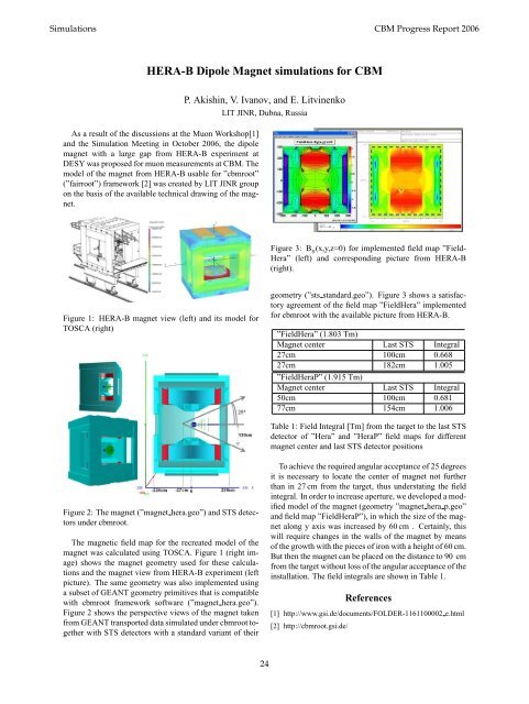
Figure 1: HERA-B magnet view (left) and its model for<br />
TOSCA (right)<br />
Figure 2: The magnet (”magnet hera.geo”) and STS detectors<br />
under cbmroot.<br />
The magnetic field map for the recreated model of the<br />
magnet was calculated using TOSCA. Figure 1 (right image)<br />
shows the magnet geometry used for these calculations<br />
and the magnet view from HERA-B experiment (left<br />
picture). The same geometry was also implemented using<br />
a subset of GEANT geometry primitives that is compatible<br />
with cbmroot framework software (”magnet hera.geo”).<br />
Figure 2 shows the perspective views of the magnet taken<br />
from GEANT transported data simulated under cbmroot together<br />
with STS detectors with a standard variant of their<br />
P. Akishin, V. Ivanov, and E. Litvinenko<br />
LIT JINR, Dubna, Russia<br />
24<br />
Figure 3: By(x,y,z=0) for implemented field map ”Field-<br />
Hera” (left) and corresponding picture from HERA-B<br />
(right).<br />
geometry (”sts standard.geo”). Figure 3 shows a satisfactory<br />
agreement of the field map ”FieldHera” implemented<br />
for cbmroot with the available picture from HERA-B.<br />
”FieldHera” (1.803 Tm)<br />
Magnet center Last STS Integral<br />
27cm 100cm 0.668<br />
27cm 182cm 1.005<br />
”FieldHeraP” (1.915 Tm)<br />
Magnet center Last STS Integral<br />
50cm 100cm 0.681<br />
77cm 154cm 1.006<br />
Table 1: Field Integral [Tm] from the target to the last STS<br />
detector of ”Hera” and ”HeraP” field maps for different<br />
magnet center and last STS detector positions<br />
To achieve the required angular acceptance of 25 degrees<br />
it is necessary to locate the center of magnet not further<br />
than in 27 cm from the target, thus understating the field<br />
integral. In order to increase aperture, we developed a modified<br />
model of the magnet (geometry ”magnet hera p.geo”<br />
and field map ”FieldHeraP”), in which the size of the magnet<br />
along y axis was increased by 60 cm . Certainly, this<br />
will require changes in the walls of the magnet by means<br />
of the growth with the pieces of iron with a height of 60 cm.<br />
But then the magnet can be placed on the distance to 90 cm<br />
from the target without loss of the angular acceptance of the<br />
installation. The field integrals are shown in Table 1.<br />
References<br />
[1] http://www.gsi.de/documents/FOLDER-1161100002 e.html<br />
[2] http://cbmroot.gsi.de/