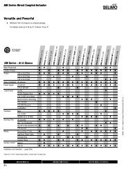
Single-Width Centrifugal Fan Performance Supplement - Greenheck
Single-Width Centrifugal Fan Performance Supplement - Greenheck
Single-Width Centrifugal Fan Performance Supplement - Greenheck

You also want an ePaper? Increase the reach of your titles
YUMPU automatically turns print PDFs into web optimized ePapers that Google loves.
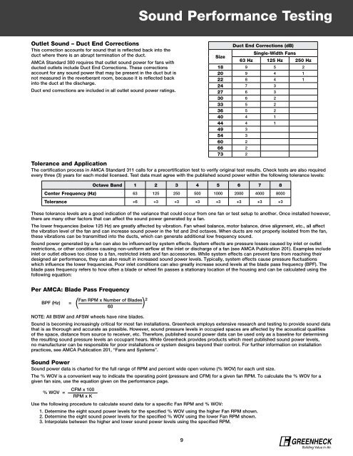
Outlet Sound – Duct End Corrections<br />
This correction accounts for sound that is reflected back into the<br />
duct where there is an abrupt termination of the duct.<br />
AMCA Standard 300 requires that outlet sound power for fans with<br />
ducted outlets include Duct End Corrections. These corrections<br />
account for any sound power that may be present in the duct but is<br />
not measured in the reverberant room, because it is reflected back<br />
into the duct at the discharge.<br />
Duct end corrections are included in all outlet sound power ratings.<br />
Per AMCA: Blade Pass Frequency<br />
BPF (Hz) = ( <strong>Fan</strong> RPM x Number of Blades ) 2<br />
60<br />
Sound <strong>Performance</strong> Testing<br />
Tolerance and Application<br />
The certification process in AMCA Standard 311 calls for a precertification test to verify original test results. Check tests are also required<br />
every three (3) years for each model licensed. Test data must agree with the published sound power within the following tolerance levels:<br />
These tolerance levels are a good indication of the variance that could occur from one fan or test setup to another. Once installed however,<br />
there are many other factors that can affect the sound power generated by a fan.<br />
The lower frequencies (below 125 Hz) are greatly affected by vibration. <strong>Fan</strong> wheel balance, motor balance, drive alignment, etc., all affect<br />
the vibration level of the fan and can increase sound power in the 1st and 2nd octaves. When ducts are not properly isolated from the fan,<br />
these vibrations can be transmitted into the ducts, which can generate additional low frequency sound.<br />
Sound power generated by a fan can also be influenced by system effects. System effects are pressure losses caused by inlet or outlet<br />
restrictions, or other conditions causing non-uniform airflow at the inlet or discharge of a fan (see AMCA Publication 201). Examples include<br />
inlet or outlet elbows too close to a fan, restricted inlets and fan accessories. While system effects can prevent fans from reaching their<br />
designed air performance, they can also result in increased sound power levels. Typically, system effects cause pressure fluctuations<br />
which influence the lower frequencies. Poor inlet conditions can also greatly increase sound levels at the blade pass frequency (BPF). The<br />
blade pass frequency refers to how often a blade or wheel fin passes a stationary location of the housing and can be calculated using the<br />
following equation:<br />
NOTE: All BISW and AFSW wheels have nine blades.<br />
Sound is becoming increasingly critical for most fan installations. <strong>Greenheck</strong> employs extensive research and testing to provide sound data<br />
that is as thorough and accurate as possible. However, sound pressure levels in occupied spaces are affected by the acoustical qualities<br />
of the space, distance from source to receiver, etc. Therefore, published sound power data can be used only as a baseline for determining<br />
the resulting sound pressure levels an occupant hears. While <strong>Greenheck</strong> provides products which meet published sound power levels,<br />
no manufacturer can be responsible for poor installations or system designs beyond their control. For further information on installation<br />
practices, see AMCA Publication 201, “<strong>Fan</strong>s and Systems”.<br />
Sound Power<br />
Sound power data is charted for the full range of RPM and percent wide open volume (% WOV) for each unit size.<br />
The % WOV is a convenient way to indicate the operating point (pressure and CFM) for a given fan RPM. To calculate the % WOV for a<br />
given fan size, use the equation given on the performance page.<br />
% WOV =<br />
CFM x 100<br />
RPM x K<br />
Octave Band 1 2 3 4 5 6 7 8<br />
Center Frequency (Hz) 63 125 250 500 1000 2000 4000 8000<br />
Tolerance +6 +3 +3 +3 +3 +3 +3 +3<br />
Use the following procedure to calculate sound data for a specific <strong>Fan</strong> RPM and % WOV:<br />
1. Determine the eight sound power levels for the specified % WOV using the higher <strong>Fan</strong> RPM shown.<br />
2. Determine the eight sound power levels for the specified % WOV using the lower <strong>Fan</strong> RPM shown.<br />
3. Interpolate between the higher and lower sound power levels using the specified RPM.<br />
9<br />
Size<br />
Duct End Corrections (dB)<br />
<strong>Single</strong>-<strong>Width</strong> <strong>Fan</strong>s<br />
63 Hz 125 Hz 250 Hz<br />
18 9 5 2<br />
20 9 4 1<br />
22 8 4 1<br />
24 7 3<br />
27 6 3<br />
30 6 2<br />
33 5 2<br />
36 5 2<br />
40 4 1<br />
44 4 1<br />
49 3<br />
54 3<br />
60 2<br />
66 2<br />
73 2<br />
®