Advanced motor protection and control - Fuji Electric America
Advanced motor protection and control - Fuji Electric America
Advanced motor protection and control - Fuji Electric America

Create successful ePaper yourself
Turn your PDF publications into a flip-book with our unique Google optimized e-Paper software.
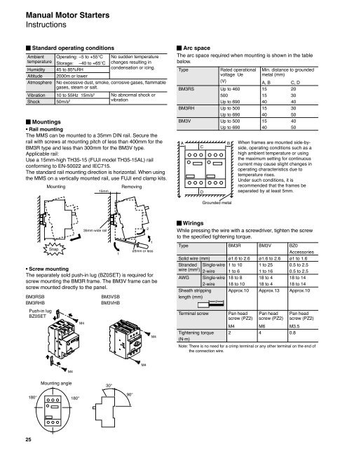
Manual Motor Starters<br />
Instructions<br />
25<br />
St<strong>and</strong>ard operating conditions<br />
Ambient Operating: –5 to +55 C<br />
temperature Storage: –40 to +65 C<br />
Humidity 45 to 85%RH<br />
Altitude 2000m or lower<br />
Atmosphere No excessive dust, smoke, corrosive gases, flammable<br />
gases, steam or salt.<br />
Vibration 10 to 55Hz 15m/s 2<br />
Shock 50m/s 2<br />
Mountings<br />
• Rail mounting<br />
The MMS can be mounted to a 35mm DIN rail. Secure the<br />
rail with screws at mounting pitch of less than 400mm for the<br />
BM3R type <strong>and</strong> less than 300mm for the BM3V type.<br />
Applicable rail:<br />
Use a 15mm-high TH35-15 (FUJI model TH35-15AL) rail<br />
conforming to EN-50022 <strong>and</strong> IEC715.<br />
The st<strong>and</strong>ard rail mounting direction is horizontal. When using<br />
the MMS on a vertically mounted rail, use FUJI end clamp kits.<br />
Mounting Removing<br />
15mm<br />
Snap<br />
35mm wide rail<br />
1<br />
2<br />
1<br />
ø5mm or less<br />
• Screw mounting<br />
The separately sold push-in lug (BZ0SET) is required for<br />
screw mounting the BM3R frame. The BM3V frame can be<br />
screw mounted directly to the panel.<br />
BM3RSB BM3VSB<br />
BM3RHB BM3VHB<br />
Push-in lug<br />
BZ0SET<br />
M4<br />
M4<br />
Mounting angle<br />
180 180<br />
30<br />
No sudden temperature<br />
changes resulting in<br />
condensation or icing.<br />
No abnormal shock or<br />
vibration<br />
90<br />
M4<br />
M4<br />
Arc space<br />
The arc space required when mounting is shown in the table<br />
below.<br />
Type Rated operational Min. distance to grounded<br />
voltage Ue metal (mm)<br />
(V) A, B C, D<br />
BM3RS Up to 460 15 20<br />
500 15 30<br />
Up to 690 40 40<br />
BM3RH Up to 500 15 30<br />
Up to 690 40 50<br />
BM3V Up to 500 15 40<br />
Up to 690 40 50<br />
A<br />
C<br />
D<br />
B<br />
Grounded metal<br />
When frames are mounted side-byside,<br />
operating conditions such as a<br />
high ambient temperature or using<br />
the maximum setting for continuous<br />
current may cause slight changes in<br />
operating characteristics due to<br />
temperature rises.<br />
Under such conditions, it is<br />
recommended that the frames be<br />
separated by at least 5mm.<br />
Wirings<br />
While pressing the wire with a screwdriver, tighten the screw<br />
to the specified tightening torque.<br />
Type BM3R BM3V BZ0<br />
Accessories<br />
Solid wire (mm) ø1.6 to 2.6 ø1.6 to 2.6 ø1 to 1.6<br />
Str<strong>and</strong>ed Single-wire 1 to 10 1 to 25 0.5 to 2.5<br />
wire (mm 2 ) 2-wire 1 to 6 1 to 16 0.5 to 2.5<br />
AWG Single-wire 18 to 8 18 to 4 18 to 14<br />
2-wire 18 to 10 18 to 4 18 to 14<br />
Sheath stripping Approx.10 Approx.13 Approx.10<br />
length (mm)<br />
Terminal screw Pan head Pan head Pan head<br />
screw (PZ2) screw (PZ2) screw (PZ2)<br />
M4 M6 M3.5<br />
Tightening torque<br />
(N·m)<br />
2 4 0.8<br />
Note: There is no need for a crimp terminal or any other terminal on the end of<br />
the connection wire.