KESSEL â Oil/fuel separator
KESSEL â Oil/fuel separator
KESSEL â Oil/fuel separator

You also want an ePaper? Increase the reach of your titles
YUMPU automatically turns print PDFs into web optimized ePapers that Google loves.
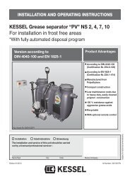
INSTALLATION AND OPERATING INSTRUCTIONS<br />
<strong>KESSEL</strong> – <strong>Oil</strong>/<strong>fuel</strong> <strong>separator</strong><br />
PE Separators NS 1,5<br />
<strong>KESSEL</strong> - <strong>Oil</strong>/<strong>fuel</strong> <strong>separator</strong><br />
NS 1,5 for underground installation<br />
Installation Commissioning Instruction<br />
The installation and service of this unit should be carried out by<br />
a licensed professional servicer<br />
Name Date Town<br />
Edition 2011/01<br />
99601.002B<br />
99601.016 B/D<br />
99601.041.B/D<br />
Product advantages<br />
Easy on-site mobility without<br />
the need for heavy<br />
machinery<br />
Simple and quick installation<br />
and hook up<br />
Recycable material<br />
Seamless body due to<br />
monolith construction –<br />
100% watertight<br />
Company - Telephone No.<br />
ID number 308-100_EN<br />
Subject to technical amendment
1. Safety Precautions<br />
By installation, use, maintenance and repair of this unit please follow all appropriate DIN<br />
/ VDE / DVGW safety precautions and accident prevention guidelines. Also please follow<br />
any local safety precautions and accident prevention guidelines established in your area.<br />
Also please observe the following:<br />
• BGV C22 (formerly VBG 37)<br />
• DIN 4124 - Safety precautions for excavations / trenches<br />
• DIN EN 1610 - Standard procedures for the installation of drainage piping<br />
BGR 117 (formerly ZH1/77) - Standard procedures for working in confined spaces<br />
Do not allow any type of wastewater into the <strong>separator</strong> which could hinder the proper separation<br />
between oils / <strong>fuel</strong>s and water.<br />
ACCESS:<br />
NO SMOKING! Smoking is strictly prohibited near or around the <strong>separator</strong> at all times !<br />
All sources of ignition or sparks are prohibited near or around the <strong>separator</strong> at all times !<br />
SLIPPERY WHEN WET! Take caution when standing / walking near the <strong>separator</strong>. During<br />
disposal, cleaning and maintenance the surrounding area can become extremely<br />
slippery due to spilled oil / <strong>fuel</strong>.<br />
SEPARATOR AREA REGULATIONS:<br />
● No access of the <strong>separator</strong> for unauthorized personnel<br />
● The location of the <strong>separator</strong> should be chosen carefully as to allow sufficient access<br />
for maintenance, inspection, repair and disposal of the <strong>separator</strong>.<br />
● The wastewater in the <strong>separator</strong> can contain skin irritants. After coming in contact<br />
with wastewater or the <strong>separator</strong> itself, it is important to wash, clean and disinfect all<br />
skin and clothing which has been contaminated.<br />
● All personnel having anything to do with the <strong>separator</strong> should have a sound knowledge<br />
of the above safety precautions.<br />
Helpful Hints:<br />
1. Manhole covers on top of <strong>fuel</strong> <strong>separator</strong>s must not be screwed or locked on.<br />
2. Manhole covers on top of <strong>fuel</strong> <strong>separator</strong>s must not have ventilation ports.<br />
3. All drains connected to the <strong>separator</strong> must not have any type of odour trap.<br />
4. All drains connected to the <strong>separator</strong> should be equipped with sludge traps.<br />
5. Wastewater must not be pumped into the <strong>separator</strong>, it must be gravity fed.<br />
6. Detergents and cleaners used to clean the <strong>separator</strong> must not be emulsifiable, they<br />
should be cleaners which separate quickly with water (contact detergent / cleaner<br />
manufacturer for additional details).<br />
2
Table of Contents<br />
1. Safety instructions ......................................................................................... Page 2<br />
2. General ......................................................................................... Page 5<br />
3. Technical specifications Dimensioned drawing ...................................................... Page 6<br />
4. Transport and storage 4.1 Transport........................................................................... Page 6<br />
4.2 Storage............................................................................. Page 6<br />
5. Installation and assembly 5.1 Installation requirements .................................................. Page 7<br />
5.2 On-site earthwork............................................................. Page 7<br />
5.3 Excavation pit................................................................... Page 7<br />
5.4 Inspection prior to installation........................................... Page 7<br />
5.5 Installation ........................................................................ Page 8<br />
6. Commissioning 6.1 Making the plant ready for operation................................ Page 9<br />
6.2 Operator's duties .............................................................. Page 9<br />
6.3 Hand-over Certificate ....................................................... Page 9<br />
7. Operation and disposal ........................................................................................................ Page 9<br />
8. Maintenance ........................................................................................................ Page 10<br />
9. Accesories/Replacement Parts ........................................................................................................ Page 11<br />
10. Warranty ........................................................................................................ Page 13<br />
11. Important contacts/info ........................................................................................................ Page 14<br />
Plant passport and factory approval ........................................................................................................ Page 15<br />
3
Dear Customer,<br />
Before the <strong>KESSEL</strong> <strong>Oil</strong> / Fuel <strong>separator</strong> is installed and placed in operation please carefully read and follow all of the instructions<br />
contained in this Installation, Maintenance and User's Manual.<br />
Upon delivery of the <strong>KESSEL</strong> <strong>separator</strong> please thoroughly inspect the <strong>separator</strong> to make sure that it has not been<br />
damaged during shipping. In case damage has occurred to the <strong>separator</strong>, please follow the instructions listed in the<br />
“Guarantee” section of this user's manual.<br />
4
● <strong>KESSEL</strong> oil/<strong>fuel</strong> <strong>separator</strong><br />
● for underground installation.<br />
● For <strong>fuel</strong>s / oils of mineral origin with densities up to 0.95<br />
g/cm3.<br />
● With self actuating emergency closure float switch.<br />
This <strong>separator</strong> is not for use for treatment of stabile emulsified<br />
<strong>fuel</strong>s / oils. It is also not for use with fats / oils from plant<br />
or animal origin.<br />
● <strong>Oil</strong> / Fuel Separator<br />
This <strong>separator</strong> can be used for the following:<br />
1. Treatment of oil / <strong>fuel</strong> contaminated surface run-off of gasoline<br />
stations, oil storage facilities, <strong>fuel</strong> transfer facilities,<br />
parking areas and streets.<br />
2. For the treatment of wastewater run-off from private <strong>fuel</strong><br />
pumps, private cleaning / washing areas and private vehicle<br />
repair facilities.<br />
3. For pre-treatment of wastewater before entry into primary<br />
treatment systems<br />
In cases 1 and 2 above, the treated wastewater is allowed to<br />
be drained into the main public drainage network. In the case<br />
that the treated wastewater is to be drained into a nearby<br />
water resource (lake / river), permission must first be granted<br />
by the governing local authority.<br />
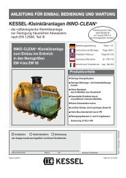
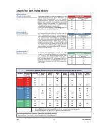
● <strong>Oil</strong> / Fuel Separator<br />
<strong>Oil</strong> / Fuel <strong>separator</strong>s main purpose is to remove mineral oil<br />
contaminants before the wastewater is drained into local sewage<br />
systems or public watershed areas. The <strong>separator</strong>s<br />
operate with the gravity principle in that the oil / <strong>fuel</strong> contaminants<br />
(being of a lower specific weight than water) float to<br />
the surface of the <strong>separator</strong> before reaching the <strong>separator</strong>ʼs<br />
outlet. The inlet of the <strong>separator</strong>, connected to nearby drains<br />
without odor traps, is hydraulically designed to distribute the<br />
incoming wastewater in an evenly manner which optimizes<br />
the separation efficiency. Sludge and sediment, with a specific<br />
gravity higher than water, settle to the base of the chamber<br />
while <strong>fuel</strong> and oil particles float to the surface.<br />
The integrated emergency closure switch (float switch) prevents<br />
oil / <strong>fuel</strong> from flowing out of the <strong>separator</strong>.<br />
5<br />
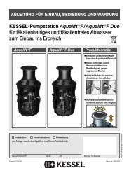
2. Application<br />
● Self closing float switch<br />
<strong>Oil</strong> and oil/<strong>fuel</strong> <strong>separator</strong>s are equipped with a self<br />
closing float switch which prevents oil / <strong>fuel</strong> from flowing out<br />
of the <strong>separator</strong>ʼs outlet. In <strong>KESSEL</strong> oil / <strong>fuel</strong> <strong>separator</strong><br />
systems, this consists of a float switch which is installed in a<br />
guide pipe which during operation is full of water. The float<br />
switch is calibrated to float in water and to sink in fluids with<br />
a density at or below 0.95 g/cm3. In the case that the <strong>fuel</strong><br />
storage capacity of a <strong>separator</strong> has been reached but the<br />
<strong>separator</strong> is not emptied / disposed, then the float switch will<br />
sink in the guide pipe and completely close off the <strong>separator</strong>ʼs<br />
outlet. This float switch closure valve is an emergency<br />
protective device which should never close if the <strong>separator</strong><br />
is properly operated<br />
Inlet<br />
<strong>Oil</strong> / Fuel<br />
Storage<br />
Water<br />
Sludge Chamber<br />
Outlet<br />
Float Switch
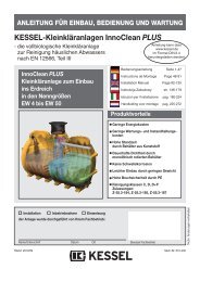
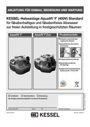
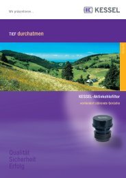
Dimensioned Drawing<br />
NS<br />
1,5<br />
1,5<br />
1,5<br />
LW<br />
(mm)<br />
400<br />
800<br />
1000<br />
Sludge chamber<br />
(l)<br />
17<br />
130<br />
360<br />
Qmax.<br />
(l/s)<br />
1,5<br />
1,5<br />
1,5<br />
DN<br />
100<br />
100<br />
100<br />
3. Technical specifications<br />
L<br />
(mm)<br />
582<br />
1091<br />
1425<br />
B<br />
(mm)<br />
520<br />
1012<br />
1300<br />
T<br />
min max<br />
231 324<br />
518 942<br />
570 995<br />
h2<br />
(mm)<br />
389<br />
508<br />
630<br />
h1<br />
(mm)<br />
342<br />
461<br />
583<br />
<strong>Oil</strong>/<strong>fuel</strong> (l)<br />
17,6<br />
70,5<br />
110<br />
Overhang<br />
(mm)<br />
50<br />
50<br />
70<br />
6<br />
Weight<br />
(kg)<br />
4. Packaging, transport and storage<br />
The chapter "Safety instructions" must be heeded!<br />
4.1 Transport<br />
Transportation of the <strong>KESSEL</strong> <strong>separator</strong> should be handled<br />
only by a transporter who has the proper knowledge, equipment<br />
and employees to handle such a product. During transport the<br />
<strong>separator</strong> must be firmly fixed into position and must not be allowed<br />
to move or shift in place. It also must be protected from<br />
other objects coming in contact with the <strong>separator</strong><br />
during transport.<br />
If and when the <strong>separator</strong> is lifted it is important to follow the following<br />
correct procedures: The <strong>separator</strong> is not to be lifted with<br />
the use of steel cables or chains. Proper equipment are heavy<br />
duty cloth or hemp straps designed to handle the corresponding<br />
loads. In instances where a forklift is used, secure the <strong>separator</strong><br />
to the forklift with appropriate cloth / hemp securing straps.<br />
4.2 Storage<br />
12<br />
74<br />
110<br />
Art.No.<br />
99601.002B<br />
99601.016B/D<br />
99601.041B/D<br />
total volume<br />
(l)<br />
43<br />
230<br />
580<br />
In cases where the <strong>separator</strong> needs to be temporarily stored before<br />
installation, it is important that the <strong>separator</strong> is placed on<br />
firm level ground and in an area where it is protected from coming<br />
in contact with other objects. Storing the <strong>separator</strong> outdoors<br />
will not cause any problems.
During the intermediate storage of the <strong>separator</strong> and<br />
until completion of the installation work, suitable safeguarding<br />
measures must be taken at the building site to<br />
prevent accidents and damage to the <strong>separator</strong><br />
The chapter "Safety instructions" must be heeded.<br />
5.1 Installation Requirements<br />
Installation of a oil / <strong>fuel</strong> <strong>separator</strong> should be handled only a<br />
professional installation company with experience in this<br />
field. The soil / earth in the area of installation must be tested<br />
to determine if is appropriate or not for the installation of a<br />
polymer <strong>separator</strong> (soil classification according to DIN<br />
18196). The maximum groundwater height in the area of installation<br />
must be determined. Max load class of vehicles driving<br />
over the <strong>separator</strong> as well as the final installation depth<br />
of the <strong>separator</strong> must be determined before specifying / ordering<br />
the <strong>separator</strong>.<br />
The underground installed <strong>separator</strong> should be installed as<br />
close as possible to the drains connected to it. In certain<br />
circumstances, the drainage pipe leading to the <strong>separator</strong><br />
should be thermally insulated or heated. The vertically adjustable<br />
upper sections allow easy connection of the inlet and<br />
outlet of the <strong>separator</strong>s. The load class B and D cast iron<br />
manhole covers are not equipped with screws and are in accordance<br />
with EN 124.<br />
5.2 On-site earthwork<br />
The <strong>separator</strong> should only be installed in areas with soil<br />
classification Group G1 to G2 according to ATV-DVWU-A127.<br />
Sub-base Gravel / process<br />
(max 8/16) according to DIN 4226-1.<br />
Base Sand<br />
Side backfill material Gravel / process<br />
(max 8/16) according to DIN 4226-1<br />
Cover Asphalt, paving stores, concrete<br />
4. Installation and assembly<br />
7<br />
5.3 Trench preparation / Backfilling<br />
The sub-base of the installation trench should be a 30cm<br />
thick flat compacted layer of 8/16 gravel / process, Dpr =<br />
95%). On top of the sub-base should be a 3-10cm thick flat<br />
compacted layer of sand. Lateral space between <strong>separator</strong><br />
sides and trench walls should be a minimum of 70 cm.<br />
Trench walls should conform to DIN 4124.<br />
The depth of installation should take into consideration the<br />
minimum and maximum allowable soil coverage (MIN≤ TEÜ<br />
≤ MAX – see dimensioned drawing).<br />
● Installation in sloped areas:<br />
In the case that the <strong>separator</strong> is to be installed in a sloped<br />
location, a proper retaining wall should be designed and<br />
constructed.<br />
● Frost level:<br />
In the case that the <strong>separator</strong> will be in operation through<br />
the winter, it is important that the inlet and outlet to the<br />
<strong>separator</strong> is installed below the local frost level to assure proper<br />
wastewater flow and operation throughout the season<br />
5.4 Inspection prior to installation<br />
Shortly before the <strong>separator</strong> is to be installed in the excavation<br />
it is important that the following is checked.<br />
- <strong>separator</strong> walls are in pristine condition<br />
- Sub-base and base have been properly constructed and<br />
compacted<br />
- Base material is according to specification
5.5 Installation<br />
● Installation<br />
The <strong>separator</strong> is to be carefully lowered into the excavation<br />
and placed on the compacted sand base (see ‚Transportʼ<br />
chapter).<br />
Please note:<br />
Weather influences or cooling of the chamber during installation<br />
(due to filling with cold water) could result in slight dimensional<br />
changes of <strong>separator</strong>s, wastewater treatment systems<br />
and rainwater storage tanks in comparison with dimensions listed<br />
in catalogs or drawings. Before installation of the chamber<br />
it is recommended that the exact dimensions of the chamber<br />
being installed (especially the chamber height) is checked.<br />
● Separator Filling<br />
Prior to backfilling the excavation, the <strong>separator</strong> should be<br />
completely filled with water.<br />
● Backfilling Excavation<br />
Lateral space between <strong>separator</strong> walls and excavation walls<br />
should be a minimum of 70cm. The excavation should be<br />
backfilled in 30cm increments / layers with each layer being<br />
properly compacted (min- Dpr=95%).<br />
Be sure to prevent movement of the <strong>separator</strong> or damage to<br />
the walls during backfilling. If the <strong>separator</strong> is to be installed<br />
in a load class D (40.0 ton) area, a steel re-enforced concrete<br />
load support platform needs to be installed on the surface of<br />
the <strong>separator</strong> (drawings for this platform are available from<br />
<strong>KESSEL</strong> if required).<br />
● Connections<br />
After the excavation has been incrementally filled and compacted<br />
up to the inlet / outlet level, connection pipes below<br />
the local frost level should be laid and connected to the inlet<br />
/ outlet.<br />
● Before installing the <strong>KESSEL</strong> upper sections be sure<br />
to insert the gasket into the recessed opening of the access<br />
shaft. Lubricated the gasket and insert the polymer upper<br />
section to the desired height / position. Tightening the supplied<br />
clamping ring will firmly set the upper section in position<br />
– final height / slope adjustments can be make with the<br />
three adjustment bolts (bolts should be in the up-side-down<br />
position). Final backfilling and compacting can now take<br />
place. If a deeper installation depth is required, use a KES-<br />
SEL extension section.<br />
● Please see the following table for information regarding the<br />
maximum oil / <strong>fuel</strong> storage capacity of the available <strong>separator</strong>s.<br />
This information is based on a oil / <strong>fuel</strong> with a density<br />
of 0,85 g/cm 3<br />
5. Installation and assembly<br />
NS<br />
1,5<br />
1,5<br />
1,5<br />
LW<br />
(mm)<br />
400<br />
800<br />
100<br />
In the case of an outlet blockage or the closure of the emergency<br />
float switch, special installation instructions should be<br />
followed in order to prevent oil / <strong>fuel</strong> from overflowing out of<br />
the manhole covers. This requires the manhole covers to be<br />
a higher than the lowest drain connected to the <strong>separator</strong>.<br />
This height is the following:<br />
- Base of manhole cover should be higher than the cover of<br />
the lowest connected rain in cases that no rainwater can<br />
enter the <strong>separator</strong>.<br />
- In the case that rainwater can enter the <strong>separator</strong>, the base<br />
of the <strong>separator</strong> cover must be higher than the highest possible<br />
back up level of rainwater.<br />
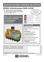
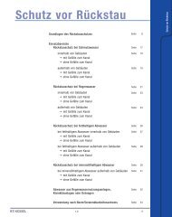
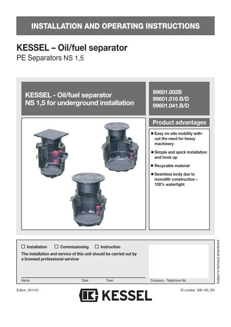
5.6 Installation heights for alarm systems<br />
Chamber body<br />
8<br />
Sludge Chamber<br />
(l)<br />
17<br />
130<br />
360<br />
<strong>Oil</strong>-Chamber<br />
(l)<br />
17,6<br />
70,5<br />
110<br />
Overstand<br />
(mm)<br />
50<br />
50<br />
70<br />
Measured from interior Measured from interior<br />
base of <strong>separator</strong> base of <strong>separator</strong><br />
Height Height<br />
<strong>Oil</strong> / <strong>fuel</strong> level sensor<br />
(mm)<br />
Overflow sensor
The chapter "Safety instructions" must be heeded.<br />
6.1 Setting up for operation<br />
Before the <strong>separator</strong> is put into operation, please make sure<br />
that:<br />
the <strong>separator</strong> is clean and the interior is free from any objects<br />
which may have been placed inside during shipping<br />
or installation.<br />
the <strong>separator</strong> is completely filled with clean cold water.<br />
Completely filling the <strong>separator</strong> is complete when water<br />
begins to drain from the outlet.<br />
6.2 Initial Instructions<br />
Placing the <strong>separator</strong> into full operation is normally handled<br />
by a licensed tradesman although upon request can be handled<br />
by a <strong>KESSEL</strong> representative.<br />
The following personnel should be on hand when the initial<br />
instructions for placing the <strong>separator</strong> into operation are given:<br />
Building facilities manager<br />
Building maintenance workers<br />
Contracted plumber / tradesman<br />
Contracted disposal company<br />
What to do:<br />
Check to make sure the <strong>separator</strong> is completely watertight.<br />
Check to make sure that during transport and<br />
installation that no damage to the <strong>separator</strong> was<br />
Disposal intervals:<br />
The <strong>fuel</strong> / oil collected in the <strong>separator</strong> should be collected /<br />
disposed when the level has reached 80% of the maximum<br />
storage capacity. Disposal of collected sludge in the base of<br />
the <strong>separator</strong> should be collected / disposed when the level<br />
has reached 50% of the maximum sludge storage capacity.<br />
Art.No.<br />
99601.002<br />
99601.016<br />
99601.041<br />
Chamber body<br />
LW 400<br />
LW 800<br />
LW 1000<br />
Measured layer thickness<br />
9<br />
65 mm<br />
125 mm<br />
180 mm<br />
6. Operation<br />
7. Disposal<br />
Sludge (50% full)<br />
caused. Check to make sure all connections to the<br />
<strong>separator</strong> (inlet, outlet, refill, rinse pipes etc.) are in<br />
perfect working order.<br />
Representative should discuss all necessary information<br />
regarding the disposal.<br />
Representative should take the customer step by step<br />
through all stages of a <strong>separator</strong> disposal<br />
After the <strong>separator</strong> has been emptied (disposed) all<br />
necessary paperwork and documentation should be<br />
handed over to the customer.<br />
The <strong>separator</strong> should be returned to service by filling<br />
the <strong>separator</strong> with fresh, cold water<br />
6.4 Hand-over of installation and userʼs manual.<br />
6.5 Completion of the commissioning report.<br />
After commissioning has been completed the <strong>separator</strong><br />
should be placed into normal operation mode.<br />
6.3 Commissioning report (see attachment)<br />
Important: Timely disposal of the <strong>separator</strong> is mandatory to<br />
insure proper function and operation of the <strong>separator</strong>.<br />
A licensed disposal company should be contracted to handle<br />
disposal of the <strong>separator</strong>. Disposal should take place when<br />
little or no wastewater is entering the <strong>separator</strong>.<br />
Disposal Voume<br />
8,5 l<br />
65 l<br />
180 l<br />
Measured layer thickness<br />
95 mm<br />
95 mm<br />
95 mm<br />
<strong>Oil</strong>/Fuel (80 % full)<br />
Disposal Voume<br />
12 l<br />
48 l<br />
75 l
1. Do it yourself inspection<br />
- Technically trained staff<br />
- Measurement of:<br />
- <strong>Oil</strong> / <strong>fuel</strong> level<br />
- Sludge level<br />
Inspection of self activating emergency closure float<br />
switch and alarm system<br />
- monthly (at least every 6 months)<br />
2 Maintenance<br />
- Technically trained staff<br />
- Measurement of:<br />
- <strong>Oil</strong> / <strong>fuel</strong> level<br />
- Sludge level<br />
- Inspection of self activating emergency closure float<br />
switch and alarm system<br />
- Disposal and cleaning, if necessary<br />
- Cleaning of sampling chamber<br />
- Data entry in log book<br />
- Every six months (at least every year)<br />
3. General inspection<br />
- By licensed service professional<br />
- Technically trained staff<br />
- Complete <strong>separator</strong> disposal<br />
- Cleaning<br />
- Check of proper condition and operation including:<br />
- Insure system is secure against overflowing of <strong>fuel</strong> / oil.<br />
- Condition of tank and walls<br />
- Check condition of internal parts and electrical systems.<br />
- Calibration of self activating float switch<br />
- Data entry in log book<br />
- Availability of <strong>separator</strong> certification and documents<br />
- In the case that <strong>separator</strong> treats commercial wastewater<br />
or wastewater from the cleaning of vehicles, the following<br />
is required:<br />
- Actual amount of entered wastewater (source, amount,<br />
contaminants, cleaning agents, type of oil / <strong>fuel</strong>, prevention<br />
of entrance of emulsified agents)<br />
- Sizing calculation and proof of proper operation of the<br />
<strong>separator</strong><br />
- Prior to commissioning and then every 5 years.<br />
8. Maintenance<br />
Pleaser insure that:<br />
- Installation and Userʼs Manual and all relevant documentation<br />
is placed in an accessible area near the <strong>separator</strong>.<br />
- The disposal procedure is handle as documented<br />
- The disposal is handled only by a licensed professional<br />
service company.<br />
Rights reserved for technical amendments<br />
- Please follow all local and national safety regulations<br />
- Smoking or open sources of fire is STRICTLY prohibited<br />
when <strong>separator</strong> covers are open.<br />
Technically trained staff:<br />
Definition – technically trained staff are individuals with the<br />
appropriate background, training and practical experience in<br />
the use and maintenance of oil / <strong>fuel</strong> <strong>separator</strong>s.<br />
Licensed service professional:<br />
Definition – third party individuals fully trained and licensed<br />
in the field of oil / <strong>fuel</strong> <strong>separator</strong> installation, operation, disposal<br />
and maintenance.<br />
10
9. Accessories / Replacement parts<br />
11<br />
<strong>KESSEL</strong>-Sampling Chamber B=400 for connection<br />
to <strong>separator</strong> systems<br />
For underground installation, free flowing sample availability.<br />
For installation depths T=….<br />
DN 100 / 150 inlet / outlet (required size cut off on-site),<br />
connection to SML pipe according to DIN 19522.<br />
Sampling chamber internal diameter 400mm, vertically adjustable<br />
upper section with Load Class A, B or D covers,<br />
odour tight, locked, inlet / outlet height difference – 120mm.<br />
Manufacturer: <strong>KESSEL</strong>.<br />
Installation Inlet Outlet Art.No.<br />
height T (mm) DN OD Class A Class B Class D<br />
*400-1300 100/150 110/160 915 880 A 915 880 B 915 880 D<br />
1330-1660 100 110 915 813 A 915 813 B 915 813 D<br />
1330-1660 150 160 915 823 A 915 823 B 915 823 D<br />
* Neck portion of chamber can be sawed of on-site to reduce installation<br />
height (do not cut at recessed gasket area).<br />
Article Number 915402 for deeper installations<br />
<strong>KESSEL</strong>-Extension section for sampling chambers<br />
for deeper installation<br />
Max. extension height. 600 mm<br />
Manufacturer: <strong>KESSEL</strong><br />
Art.No.<br />
- 915 402<br />
<strong>KESSEL</strong>-Extension section for underground<br />
<strong>KESSEL</strong> <strong>separator</strong> systems, polyethylene material, includes gasket<br />
Extension height Art.No.<br />
512 mm 917 406<br />
1012 mm 917 407
9. Accessories / Replacement parts<br />
<strong>KESSEL</strong><strong>KESSEL</strong> <strong>Oil</strong> / <strong>fuel</strong> level monitoring device.<br />
5 meter connection cable (extendable up to 200 meter), installation set, watertight cable<br />
connection, conduit access insert, IP 54 control unit housing, plug in ready, with LED and<br />
audible alarm and potential free contact.<br />
Art.No.<br />
917 801<br />
<strong>KESSEL</strong>-<strong>KESSEL</strong> back up / overflow monitoring device.<br />
5 meter connection cable (extendable up to 200 meters) installation set, watertight<br />
cable connection, conduit access insert, IP 54 control unit housing, plug in ready,<br />
with LED and audible alarm and potential free contact.<br />
Art.No.<br />
917 802<br />
<strong>KESSEL</strong> <strong>Oil</strong> Suction System<br />
Suction pipe B 50 with Bi 50 suction hose for on-site connection to interior of upper<br />
section, with Storz 52 C connection coupling<br />
Art.No.<br />
917 803<br />
<strong>KESSEL</strong> Sludge Extraction System<br />
Suction pipe B 50 with sludge suction funnel, 0.5m re-enforced suction hose Bi 50<br />
for on-site connection to interior of upper section, with Storz 52 C connection coupling.<br />
Art.No.<br />
917 804<br />
12
1. In the case that a <strong>KESSEL</strong> product is defective, <strong>KESSEL</strong> has<br />
the option of repairing or replacing the product. If the product<br />
remains defective after the second attempt to repair or replace<br />
the product or it is economically unfeasible to repair or replace<br />
the product, the customer has the right to cancel the<br />
order / contract or reduce payment accordingly. <strong>KESSEL</strong><br />
must be notified immediately in writing of defects in a product.<br />
In the case that the defect is not visible or difficult to detect,<br />
<strong>KESSEL</strong> must be notified immediately in writing of the defect<br />
as soon as it is discovered. If the product is repaired or replaced,<br />
the newly repaired or replaced product shall receive<br />
a new warranty identical to that which the original (defective)<br />
product was granted. The term defective product refers only<br />
to the product or part needing repair or replacement and not<br />
necessarily to the entire product or unit. <strong>KESSEL</strong> products are<br />
warranted for a period of 24 month. This warranty period begins<br />
on the day the product is shipped form <strong>KESSEL</strong> to its customer.<br />
The warranty only applies to newly manufactured<br />
products. Additional information can be found in section 377<br />
of the HGB.<br />
13<br />
10. Guarantee<br />
In addition to the standard warranty, <strong>KESSEL</strong> offers an additional<br />
20 year warranty on the polymer bodies of class I / II<br />
<strong>fuel</strong> <strong>separator</strong>s, grease <strong>separator</strong>s, inspection chambers, wastewater<br />
treatment systems and rainwater storage tanks. This<br />
additional warranty applies to the watertightness, usability<br />
and structural soundness of the product.<br />
A requirement of this additional warranty is that the product is<br />
properly installed and operated in accordance with the valid<br />
installation and user's manual as well as the corresponding<br />
norms / regulations.<br />
2. Wear and tear on a product will not be considered a defect.<br />
Problems with products resulting from improper installation,<br />
handling or maintenance will also be considered a defect.<br />
Note: Only the manufacturer may open sealed components or<br />
screw connections. Otherwise, the warranty may become null<br />
and void<br />
01.06.2010
Separator Characteristics<br />
Type _____________________________________________________________________________________<br />
Production number / production year_______________________________________________________________<br />
Weight/kg_____________________________length x width X height____________________________________<br />
EN ___ ________________________________________Approval______________________________________<br />
____________________________________________________________________________________________<br />
Sludge trap volume / l _____________________________________<strong>Oil</strong> storage volume / l _____________________<br />
Control stamp___________________________________Material_______________________________________<br />
(Accessories) ________________________________________________________________________________<br />
This unit has been checked for watertightness to be sure that it is fully operational before leaving the factory.<br />
Date Name of examiner<br />
14
Important contacts / Info<br />
Separator Type: __________________________________________________________<br />
Day / Hour __________________________________________________________<br />
Project description / Building services<br />
supervisor __________________________________________________________<br />
Address __________________________________________________________<br />
Telephone / Fax __________________________________________________________<br />
Builder __________________________________________________________<br />
Address __________________________________________________________<br />
Telephone / Fax __________________________________________________________<br />
Planner __________________________________________________________<br />
Address __________________________________________________________<br />
Telephone / Fax __________________________________________________________<br />
Contracted plumbing company __________________________________________________________<br />
Address __________________________________________________________<br />
Telephone / Fax __________________________________________________________<br />
Commissioning no. <strong>KESSEL</strong><br />
System operator / owner __________________________________________________________<br />
Address __________________________________________________________<br />
Telephone / Fax __________________________________________________________<br />
Other remarks __________________________________________________________<br />
__________________________________________________________<br />
__________________________________________________________<br />
__________________________________________________________<br />
The system operator, and those responsible, were present during the commissioning of this system.<br />
____________________________ ____________________________ ____________________________<br />
Place and Date Signature Builder Unterschrift Anlagenbetreiber<br />
15
Everything for drainage<br />
Backwater valves and cleanouts<br />
Polymer and Ecocast drains<br />
Volatile liquid traps<br />
Lifting stations, pumps, warning<br />
and control units<br />
Rainwater management systems<br />
Grease <strong>separator</strong>s<br />
<strong>Oil</strong>/<strong>fuel</strong> and oil/<strong>fuel</strong><br />
<strong>separator</strong>s<br />
Inspection chambers<br />
Custom projects for<br />
industrial applications