
Create successful ePaper yourself
Turn your PDF publications into a flip-book with our unique Google optimized e-Paper software.
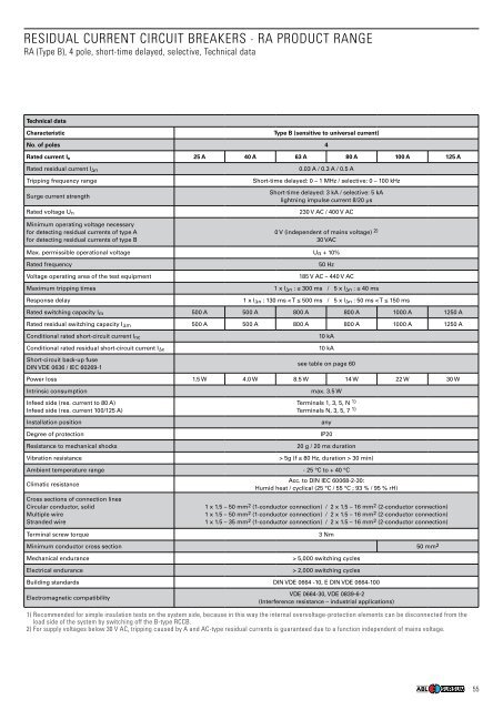
RESIDUAL CURRENT CIRCUIT BREAKERS · RA PRODUCT RANGE<br />
RA (Type B), 4 pole, short-time delayed, selective, Technical data<br />
Technical data<br />
Characteristic Type B (sensitive to universal current)<br />
no. of poles 4<br />
Rated current In 25 A 40 A 63 A 80 A 100 A 125 A<br />
Rated residual current I�n<br />
0.03 A / 0.3 A / 0.5 A<br />
Tripping frequency range Short-time delayed: 0 – 1 MHz / selective: 0 – 100 kHz<br />
Surge current strength<br />
Short-time delayed: 3 kA / selective: 5 kA<br />
lightning impulse current 8/20 µs<br />
Rated voltage Un<br />
230 V AC / 400 V AC<br />
Minimum operating voltage necessary<br />
for detecting residual currents of type A<br />
for detecting residual currents of type B<br />
0 V (independent of mains voltage) 2)<br />
30 VAC<br />
Max. permissible operational voltage Un + 10%<br />
Rated frequency 50 Hz<br />
Voltage operating area of the test equipment 185 V AC – 440 V AC<br />
Maximum tripping times 1 x l�n : ≤ 300 ms / 5 x l�n : ≤ 40 ms<br />
Response delay 1 x l�n : 130 ms < T ≤ 500 ms / 5 x l�n : 50 ms < T ≤ 150 ms<br />
Rated switching capacity lm 500 A 500 A 800 A 800 A 1000 A 1250 A<br />
Rated residual switching capacity I�m 500 A 500 A 800 A 800 A 1000 A 1250 A<br />
Conditional rated short-circuit current lnc<br />
Conditional rated residual short-circuit current I�c<br />
Short-circuit back-up fuse<br />
DIN VDE 0636 / IEC 60269-1<br />
10 kA<br />
10 kA<br />
see table on page 60<br />
Power loss 1.5 W 4.0 W 8.5 W 14 W 22 W 30 W<br />
Intrinsic consumption max. 3.5 W<br />
Infeed side (res. current to 80 A)<br />
Infeed side (res. current 100/125 A)<br />
Terminals 1, 3, 5, N 1)<br />
Terminals N, 3, 5, 7 1)<br />
Installation position any<br />
Degree of protection IP20<br />
Resistance to mechanical shocks 20 g / 20 ms duration<br />
Vibration resistance > 5g (f ≤ 80 Hz, duration > 30 min)<br />
Ambient temperature range - 25 °C to + 40 °C<br />
Climatic resistance<br />
Acc. to DIN IEC 60068-2-30:<br />
Humid heat / cyclical (25 °C / 55 °C ; 93 % / 95 % rH)<br />
Cross sections of connection lines<br />
Circular conductor, solid<br />
Multiple wire<br />
Stranded wire<br />
1 x 1.5 – 50 mm 2 (1-conductor connection) / 2 x 1.5 – 16 mm 2 (2-conductor connection)<br />
1 x 1.5 – 50 mm 2 (1-conductor connection) / 2 x 1.5 – 16 mm 2 (2-conductor connection)<br />
1 x 1.5 – 35 mm 2 (1-conductor connection) / 2 x 1.5 – 16 mm 2 (2-conductor connection)<br />
Terminal screw torque 3 Nm<br />
Minimum conductor cross section 50 mm 2<br />
Mechanical endurance > 5,000 switching cycles<br />
Electrical endurance > 2,000 switching cycles<br />
Building standards DIN VDE 0664 -10, E DIN VDE 0664-100<br />
Electromagnetic compatibility<br />
VDE 0664-30, VDE 0839-6-2<br />
(Interference resistance – industrial applications)<br />
1) Recommended for simple insulation tests on the system side, because in this way the internal overvoltage-protection elements can be disconnected from the<br />
load side of the system by switching off the B-type RCCB.<br />
2) for supply voltages below 30 V AC, tripping caused by A and AC-type residual currents is guaranteed due to a function independent of mains voltage.<br />
55