Trådlös Backkamera och Monitor Instruktions manual - KAMA Fritid
Trådlös Backkamera och Monitor Instruktions manual - KAMA Fritid
Trådlös Backkamera och Monitor Instruktions manual - KAMA Fritid

You also want an ePaper? Increase the reach of your titles
YUMPU automatically turns print PDFs into web optimized ePapers that Google loves.
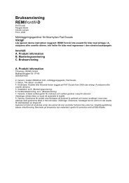
Model No.: RVC3500<br />
<strong>Trådlös</strong> <strong>Backkamera</strong> <strong>och</strong> <strong>Monitor</strong><br />
<strong>Instruktions</strong> <strong>manual</strong><br />
Viktigt:<br />
Läs igenom <strong>manual</strong>en noga före användning <strong>och</strong><br />
spara den för framtida bruk.<br />
1
Bäste Kund,<br />
Din RVC3500 trådlös backkamera <strong>och</strong> monitor kommer att underlätta för dig som förare när du<br />
vill se bakom din bil, lastbil, husvagn, husbil m.m. Vi hoppas att ni kommer få mycket nytta av<br />
produkten.<br />
Innan installation<br />
Planera installationen innan den påbörjas. Det kan vara komplicerat att installera 12 Volts<br />
applikationer i ett fordon, så det är därför extra viktigt att man går igenom hur allt skall kopplas<br />
innan installationen påbörjas.<br />
Denna enhet är trådlös, precis som alla andra trådlösa enheter kan det uppstå<br />
störningar av mobiltelefoner, Bluetooth headset, Wi-Fi routers, omvandlare m.m.<br />
.<br />
Innehåll<br />
1. <strong>Monitor</strong> <strong>och</strong> monteringsarm 2. Kamera<br />
3. Sändarbox 4. Monteringstillbehör 5. Strömkabel monitor<br />
6. Strömkabel sändarbox 7. Monteringsplåtar kamera<br />
2
Installation<br />
Följande instruktioner är generella <strong>och</strong> gäller ej på alla ställen RVC-24 monteras på. Om ni<br />
stöter på problem vid montering kontakta service@lejontrading.se.<br />
INSTALLATION AV MONITOR<br />
När platsen för montering av monitorn skall bestämmas, var noga med<br />
att ej montera den i synfältet så att den kan störa din körning.<br />
Välj plats <strong>och</strong> installera strömkabeln<br />
1. Placera monitorn på vald plats.<br />
2. Koppla in strömkabeln i monitorn samt i 12 Volts uttag. Kontrollera<br />
så<br />
att kabeln dras på ett sådant sätt så att den ej stör din bilkörning.<br />
Montera <strong>Monitor</strong><br />
Rengör platsen där monitorn skall monteras.<br />
1. Placera sugkoppen mot plant underlag.<br />
2. Pressa sugkoppen mot ytan.<br />
3. Tryck ner låsningen för att fixera sugkoppen.<br />
4. Sätt I monitorn i fästet.<br />
5. Justera in vinkeln på sugkoppsarmen så den passar din tittvinkel.<br />
För att maximera effekten på sugkoppen, rekommenderar vi att den monteras under följande<br />
omständigheter:<br />
Monteringsytans temperatur bör vara mellan 21<strong>och</strong> 38 grader C℃<br />
Montering under 10 grader C bör undvikas.<br />
Montering i direkt solljus bör undvikas.<br />
Suggkoppen bör ej exponeras för solljus under de närmaste dagarna efter montering.<br />
NOTERING: VID EXTREMT LJUSA FÖRHÅLLANDE, KAN SKÄRMEN BEHÖVA ETT PAR<br />
SEKUNDER PÅ SIG ATT STABILISERAS. VÄNTA MED ATT BACKA TILLS BILDEN ÄR<br />
STABIL OCH KLAR.<br />
STRÖMANSLSUTNING MONITOR<br />
Använd 12 Volt ciggarettanslutning för att ansluta till bilens 12-Volt uttag.<br />
Strömkabel med 12-V ciggarettadapter<br />
1. Sätt i DC-kontakten I den vänster sedan av monitorn.<br />
2. Sätt i ciggaadaptern I bilens ciggarettuttag.<br />
Denna enhet är trådlös, precis som alla andra trådlösa enheter kan det uppstå<br />
störningar av mobiltelefoner, Bluetooth headset, Wi-Fi routers, omvandlare m.m.<br />
3
MONITOR–KNAPPAR<br />
<strong>Monitor</strong>n kommer automatiskt att gå igång när man lägger i backen. Där finns 5 knappar för<br />
användaren att styra monitorn med.<br />
BLÅ LED Strömindikator<br />
När monitorn är påslagen kommer LED-lampan att lysa med ett blått sken, när monitorn är<br />
avslagen är LED lampan släckt.<br />
MENU, + <strong>och</strong> - knappar<br />
Tryck på meny för att öppna upp menyn som visas här:<br />
Tryck på meny igen för att välja ljusstyrka, kontrast <strong>och</strong> färg.<br />
Tryck på + knappen eller – knappen för att ställa in ljusstyrkan,<br />
kontrasten eller färgen. Tryck på + knappen för att öka <strong>och</strong> – knappen<br />
för att minska.<br />
För att flytta bilden tryck på meny knappen till dess att riktning är vald.<br />
Tryck sedan på + eller – snabbt tills önskat bildläge ”vänster till<br />
höger”, ”höger till vänster”<br />
eller ”upp <strong>och</strong> ner” är uppnått.<br />
De olika lägena tillåter dig att montera kameran eller monitorn höger sida upp eller upp <strong>och</strong> ner<br />
<strong>och</strong> fortfarande visa bilden korrekt på monitorn. Bilden skall vara som bilden i din backspegel.<br />
För att avsluta bild menyn, välj EXIT på skärmen med meny knappen <strong>och</strong> tryck antingen + eller –<br />
för att avsluta bild menyn.<br />
Hjälplinjer Guideline ON/OFF<br />
Tryck på hjälplinjer-knappen (GUIDELINE) Av/På för att aktivera/avaktivera denna funktion.<br />
4
KAMERAINSTALLATION<br />
Kameran kan monteras ovanför eller under registreringsskylten med skruv eller bult. Se<br />
till så att kameran ej döljs av någon utstickande detalj på fordonet. Använd medföljande<br />
vinklar för att justera in rätt vinkel på kameran.<br />
1. Montera backkameran på ett lämpligt ställe på fordonet, gärna så centrerat som möjligt, då<br />
bilden blir mer korrekt.<br />
Användning av de medföljande monteringsplåtarna<br />
Lossa nummerplåtens bultar eller skruvar <strong>och</strong> ta bort den bakre registreringsskylten.<br />
Placera medföljande monteringsplåtarna bakom nummerplåten. Fäst både nummerplåt <strong>och</strong><br />
monteringsplåtar med registreringsskyltens bultar/skruvar.<br />
Sätt i de medföljande skruvarna genom bulthålen i kameran <strong>och</strong> sedan genom bulthålen i<br />
monteringsplåtarna.<br />
5
2. Rikta kameran vänster/höger <strong>och</strong> dra tillfälligt åt medföljande bultar/skruvar. Om det krävs att<br />
man vinklar ner kameran, montera kameran med de medföljande kilarna på<br />
monteringsplattan enligt nedan.<br />
3. Kabeln från backkameran måste dras in i bilen till backljuset på ett lämpligt <strong>och</strong> snyggt sätt.<br />
Försök att dra kabeln så gömd som möjligt då den annars lätt kan fastna, typ vid biltvätt.<br />
4. Vissa bilar har en genomföring där registreringsskyltens belysning sitter, borra annars ett hål<br />
där kameran är monterad. När väl platsen för genomföringen skall göras, montera loss<br />
backkameran igen. Finns det en öppning hoppa över de följande stegen.<br />
5. Om ett hål måste borras för kabelgenomföringen, välj då att göra hålet så när backkameran<br />
som möjligt. Innan borrning påbörjas måste det undersökas vad som finns på baksidan av<br />
det kommande hålet.<br />
6. När hålet är gjort, sätt i skyddshöljet som medföljer, detta för att förhindra att bilens metall<br />
skaver sönder kabeln.<br />
7. Montera sändarboxen på insidan av bagageluckan (sändarboxen är ej vattentät). Anslut<br />
kamerakabeln <strong>och</strong> strömkabeln till sändarboxen.<br />
8. Sök nu rätt på bilens backljus. Vrid om bilnyckeln ti ACC (starta ej motorn), drag åt<br />
parkeringsbromsen <strong>och</strong> lägg växeln i back läget. Se nu var backljuset är placerat, kommer att<br />
lysa vitt.<br />
9. Sök nu rätt på kablaget till backljuset samt vilket som är + <strong>och</strong> -, drag nu dit backkamerans<br />
strömkabel dit, strömkabeln måste fastsättas på ett säkert sätt så att den ej kan fastna i några<br />
komponenter eller liknande då bagageluckan rör sig upp <strong>och</strong> ner hela tiden. Dra aldrig kabeln<br />
på utsidan av bilen.<br />
10. De flesta bilar har 2 kablar kopplade till backljuset. Normalt sett är – kabeln svart <strong>och</strong> + är den<br />
färgade kabeln, använd en 12 Volts multimeter för att vara säker.<br />
11. När det är konstaterat vilket som är + <strong>och</strong> -, stäng av tändningen, avlägsna sedan<br />
minuskabeln från batteriet.<br />
12. Använd de medföljande kabel delarna för att koppla in + kabeln till backljusets + kabel.<br />
6
13. Använd de medföljande kabel delarna för att koppla in - kabeln till backljusets - kabel.<br />
14. När installationen är slutförd, koppla åter in minuskabeln till batteriet.<br />
För in den existerande För in kabeln från Tryck ihop metallbiten Strömdelaren<br />
kabeln i strömdelaren. backkameran. Stäng sedan locket. Efter stängning<br />
Tekniska specifikationer<br />
Kamera<br />
Ström försörjning 12V DC<br />
Ström förbrukning < 150mA<br />
Bild sensor CMOS<br />
Nummer av pixlar 640X480<br />
Upplösning >350<br />
Optisk Lins 2.4 mm / F2.0<br />
Kamera bilds vinkel 120 grader<br />
<strong>Trådlös</strong> sändare<br />
Sändnings frekvens 2414 MHz<br />
RF sändnings distans (öppen yta) > 30M<br />
LCD monitor<br />
Volt 12 DC<br />
Standby förbrukning < 30mA<br />
Ström förbrukning < 350mA<br />
Storleken på LCD skärmen 3.5<br />
Nummer av pixlar 480x234<br />
Betrakningsvinkel 90<br />
Arbetstemperatur -10 to +45 o C<br />
7
TESTA SYSTEMET<br />
1. Kontrollera så att minuskabeln till batteriet är ordentligt fastsatt.<br />
2. Vrid bilnyckeln till ACC, starta ej motorn.<br />
3. Drag åt parkeringsbromsen, lägg i backväxeln.<br />
4. Nu kommer en bild att visas på monitorn. Stämmer ej bilden med backspegeln, tryck då på<br />
meny-knappen <strong>och</strong> ändra bilden.<br />
När testen är slutförd måste allting återställas <strong>och</strong> kabeldragningarna skall snyggas till för fast<br />
installation.<br />
Skruva tillbaka allting som plockats ner <strong>och</strong> spänn skruvarna ordentligt.<br />
Göm alla kablar bakom paneler <strong>och</strong> mattor.<br />
Använd medföljande buntband.<br />
Vi på Lejon Trading & Co AB förbehåller oss rätten att förbättra samt ändra specifikationer <strong>och</strong><br />
prestanda utan speciellt meddelande. Gå in på www.lejontrading.se för att se uppdateringar.<br />
8
Model No.: RVC3500<br />
Wireless Back-Up Camera and <strong>Monitor</strong><br />
OWNER’S MANUAL<br />
IMPORTANT:<br />
READ THESE INSTRUCTIONS BEFORE USE AND RETAIN<br />
FOR FUTURE REFERENCE.<br />
9
Dear Customer,<br />
CONGRATULATIONS. The RVC3500 Wireless Back-up Camera and <strong>Monitor</strong>, when used as<br />
described, will improve your ability to see behind your car, truck, RV, or mini-van. We have taken<br />
numerous measures in quality control to ensure that your product arrives in top condition, and<br />
will perform to your satisfaction.<br />
Before You Install<br />
Automotive video equipment installations can be difficult at times, even to the most<br />
experienced of installation technicians. If you are not confident working with 12 volt DC<br />
vehicle wiring, removing and reinstalling interior panels, carpeting, dashboards or other<br />
components of your vehicle, contact the vehicle’s manufacturer, or consider having the<br />
Wireless Back Up Camera and <strong>Monitor</strong> professionally installed.<br />
This device, as well as all other wireless devices, may be subject to interference.<br />
Interference may be caused by cell phones, Bluetooth headsets, Wi-FI routers,<br />
power lines and other various electrical equipment, etc.<br />
.<br />
Parts<br />
1. <strong>Monitor</strong> and Mounting Arm 2. Camera<br />
3. Transmitter Box 4. Camera Mounting Accessories<br />
5. <strong>Monitor</strong> Power Cable 6.Transmitter Box Power Cable 7.Camera Mounting Plates<br />
10
Installation<br />
These instructions do not apply to all vehicles. They are only meant as a general guide<br />
due to the number of different makes & models.<br />
For vehicle specific questions contact your vehicle’s manufacturer.<br />
MONITOR INSTALLATION<br />
When choosing a location to mount the monitor, make sure the monitor is in an area that will not<br />
obstruct your vision while driving.<br />
Choose a Location and Install Power Cable<br />
1.Temporarily place the monitor in the location that you have chosen<br />
2.Route the power cable to the vehicle’s cigarette lighter socket/12V<br />
power outlet. The cable must not interfere with the safe operation of<br />
the vehicle.<br />
Mounting the <strong>Monitor</strong><br />
Before mounting the monitor, clean the mounting surface well.<br />
1.Position the suction mount to the smooth surface which suits your<br />
requirement.<br />
2.Press the suction cap against the smooth surface such as windshield<br />
or dashboard.<br />
3.Press the lock down to attach and fix the mount to the surface.<br />
4.Snap in the monitor to the suction mount.<br />
5.Adjust the mounting arms to suit your view angle to the monitor and<br />
tighten the screws on the mount to fix the position.<br />
To maximize the effectiveness of the suction mount, it is recommended that the application be<br />
performed under the following conditions:<br />
Surface temperature should be between 70 o F and 100 o F (21 o C and 38 o C).<br />
Application below 50 o F (10 o C) should be avoided.<br />
Application should not occur in direct sunlight.<br />
Mounting should be protected from exposure to direct sunlight for a period of 24 hours.<br />
NOTE: UNDER EXTREME BRIGHT LIGHT CONDITIONS, THE SCREEN IMAGE MAY TAKE A<br />
FEW SECONDS TO STABLIZE. PLEASE WAIT UNTIL THE IMAGE HAS STABLIZED BEFORE<br />
BACKING UP.<br />
MONITOR POWER CONNECTION<br />
Use the 12 Volt cigarette lighter adaptor plugged into the vehicle’s cigarette lighter socket.<br />
Power Cable with 12 Volt Cigarette Lighter Adaptor<br />
1. Insert the small 12 Volt DC plug of the power cable into the right side of the monitor.<br />
2. Plug the 12 Volt cigarette lighter adaptor into the vehicle’s cigarette lighter socket.<br />
11
This device, as well as all other wireless devices, may be subject to interference. Interference<br />
may be caused by cell phones, Bluetooth headsets, Wi-FI routers, power lines and other<br />
various electrical equipment. Etc.<br />
MONITOR CONTROLS<br />
The monitor will automatically turn ON when the vehicle is in reverse gear. Also, there are 5<br />
control buttons available for user to have their controls.<br />
Power On/Off Button - BLUE LED Power Indicator<br />
Press POWER ON/OFF button to supply power to monitor. When monitor image is ON, the blue<br />
LED will be lit. If there is power to the monitor but the monitor image is off, the blue LED will blink<br />
on and off. When the monitor power is OFF, no picture can appear on the screen and the blue<br />
LED will be off.<br />
When power supplied is on, the monitor will automatically turn ON and an image will appear<br />
when the vehicle is in reverse gear. There are 5 buttons available for the user to control the<br />
screen image.<br />
When power supplier is off, the blue LED will be in series flickering for 1 second.<br />
MENU, + and - Buttons<br />
Press MENU button to enter the menu screen as shown below:<br />
Repeat pressing MENU button to select BRIGHTNESS, CONTRAST<br />
or COLOR controls.<br />
Press + button or – button to adjust settings within the control selected.<br />
Press the + button to increase the value and the – button to decrease<br />
the value.<br />
To change the orientation of the screen image, press MENU button until<br />
DIRECTION is selected. Then press + or – repeatedly until desired<br />
screen orientation “left to right”, “right to left” or “upside down”<br />
is achieved.<br />
The different views allow you to mount the camera and / or monitor either right side up or<br />
upside down and still display the image correctly on the monitor. The image displayed should<br />
match your rear view mirror.<br />
To exit the menu screen, select EXIT on the screen using the MENU button and press either +<br />
or – to exit the menu screen.<br />
Guideline ON/OFF<br />
Press GUIDELINE ON/OFF button to switch ON or OFF the on-screen-display guideline.<br />
12
CAMERA INSTALLATION<br />
You can mount the camera using the top or bottom mounting bolts or screws of license<br />
plate. Ensure the camera viewing is not obstructed. The supplied wedge shaped spacers<br />
can adjust the camera mounting angle vertically.<br />
1. Loosen the license plate bolts or screws and remove the rear license plate.<br />
2. Please the supplied mounting plates behind the license plate bracket. Secure both license<br />
plate bracket and mounting plates with the license plate bracket bolts/screws.<br />
3. Insert each supplied screws through the bolt holes of the camera, then through the bolt holes<br />
of the mounting plates.<br />
13
4. Align the camera left/right and temporarily tighten the supplied bolts/screws. If required to<br />
angle the camera down, mount the camera with the supplied wedges onto the mounting plate<br />
as shown below.<br />
.<br />
5. Mount the license plate onto the license plate bracket.<br />
6. Choose a routing path for the camera’s power cable through the vehicle’s body to the reverse<br />
light circuit. If in doubt, seek professional installation assistance.<br />
7. Some vehicles may have a hole to pass the wire through. For example, the location of the<br />
license plate light is mounted, or you can drill a hole close to the power cable that will attach<br />
to the camera. Once you have determined where the cable will enter the vehicle’s trunk,<br />
remove the camera. If you are able to use an existing opening or hole, skip the next two<br />
steps.<br />
8. If you are going to drill a hole, choose a location as close to the camera where the power cable<br />
comes out. Before you drill a hole you MUST CHECK WHAT IS BEHIND THE DRILLING<br />
LOCATION. If there are any vehicle components, like electrical parts or fuel system<br />
components behind the drilling location, you must take precaution not to damage them.<br />
Remove the license plate and camera before drilling.<br />
9. After you have drilled a half inch (1/2”) hole, pass the camera wire connector through the hole<br />
into the vehicle and place the grommet in the hole around the camera wire. You must use the<br />
grommet to prevent the metal edge of the hole from cutting the camera cable.<br />
10. Mount the transmitter box inside the trunk. Connect the camera cable and the power cable to<br />
the transmitter box.<br />
11. Find the vehicle’s reverse lights. Turn the vehicle’s ignition key to the accessory position,<br />
engage the parking brake and put the car in reverse. Look at the vehicle’s tail lights to see<br />
where the reverse white lights are located.<br />
To locate the reverse light’s 12V+ wire, it is necessary to access to the rear part of the<br />
vehicle’s tail light.<br />
For help locating the vehicle’s reverse light circuit, contact your vehicle’s manufacturer for<br />
vehicle specific wiring diagrams.<br />
12. Once you have located the reverse light circuit, you need to route the power cable supplied to<br />
that location. Fasten the power cable securely to prevent it from being caught on any vehicle<br />
component like the trunk hinge. Never route the cable on the outside of the vehicle.<br />
14
13. Locate reverse light socket and remove light bulb. There are two wires connected to the<br />
reverse light sockets on most vehicles. Usually the negative wire is black and the positive wire is<br />
a colored wire. If you are uncertain about the wiring, use a 12 volt multimeter (available at most<br />
auto parts stores) to determine which wire is positive. Follow the manufacturer’s<br />
instructions for the safe use of the multimeter.<br />
14. After determining which wire is the positive and which is the negative, turn off the ignition key,<br />
then remove the battery’s negative cable.<br />
15. Splice the red wire using the supplied wire clamp to the reverse light’s positive (+) wire. Use a<br />
set of slip joint pliers to squeeze the METAL BLADE and insure good connection of both<br />
wires.<br />
Insert the existing wire Insert the wire to be Crimp clamp with pliers, Wire Clamp after locking<br />
to be tapped to the clamp. attached to the clamp. then close lock<br />
16.You may not need to use the wire clamp. The power cable can be wired directly to the reverse<br />
light circuit by stripping the reverse light wires then twisting the camera wires to the exposed<br />
reverse light wires. Once connected, wrap with electrical tape. Do not attempt this if you<br />
17.Next splice the black wire of the camera’s power cable to the reverse light’s negative (-) wire<br />
or ground.<br />
18.Replace the reverse light bulb and re-install the light socket. Secure all the wires with cable<br />
ties or electrical tape. Reattach the negative battery cable to the battery afterwards.<br />
15
Technical Specification<br />
Camera<br />
Operating Voltage range 12V DC<br />
Current consumption < 150mA<br />
Image Sensor CMOS<br />
No. of pixel 640X480<br />
Resolution >350<br />
Optical Lens 2.4 mm / F2.0<br />
Camera View Angle 120 degree<br />
Wireless Transmitter<br />
Transmission Frequency 2414 MHz<br />
RF transmission distance (open space) > 30M<br />
LCD monitor<br />
Operation Voltage 12 DC<br />
Standby Current < 30mA<br />
Operation Current < 350mA<br />
LCD display screen size 3.5<br />
No. of pixel 480x234<br />
Viewing angle 90<br />
Operation Temperature -10 to + 45 o C<br />
Storage Temperature -30 to + 80 o C<br />
TESTING THE SYSTEM<br />
1. Reattach the vehicle’s negative battery cable.<br />
2. Turn the ignition key to the accessory position, do not start the vehicle.<br />
3. Engage the parking brake, put the shifter in the reverse position.<br />
4. Look at the monitor, if the image does not match your rear view mirror press the Image<br />
Orientation button on the monitor to correct the image.<br />
After testing the unit and you are satisfied with the route you have chosen for the cabling, you<br />
must permanently install it.<br />
Fully tighten the license plate bolts.<br />
Route all wires behind interior panels or under carpeting so they are hidden.<br />
Use supplied cable ties to neatly gather any excess wire.<br />
16