Q.bloxx A101
Q.bloxx A101
Q.bloxx A101

Create successful ePaper yourself
Turn your PDF publications into a flip-book with our unique Google optimized e-Paper software.
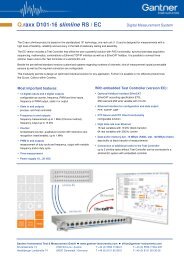
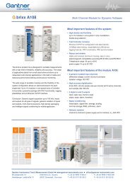
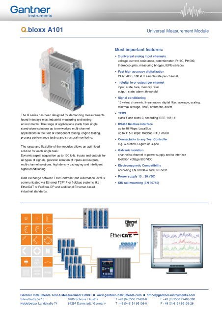
Q.<strong>bloxx</strong> <strong>A101</strong><br />
The Q.series has been designed for demanding measurements<br />
found in todays most industrial measuring and testing<br />
environments. The range of applications starts from single<br />
stand-alone solutions up to networked multi-channel<br />
applications in the field of component testing, engine testing,<br />
process performance testing and structural monitoring.<br />
The range and flexibility of the modules allows an optimized<br />
solution for each single task:<br />
Dynamic signal acquisition up to 100 kHz, inputs and outputs for<br />
all types of signals, galvanic isolation of inputs and outputs,<br />
multi-channel solutions, high density packaging and intelligent<br />
signal conditioning.<br />
Data exchange between Test Controller and automation level is<br />
communicated via Ethernet TCP/IP or fieldbus systems like<br />
EtherCAT or Profibus-DP and additional Ethernet-based<br />
industrial standards.<br />
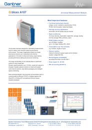
Most important features:<br />
2 universal analog input channels<br />
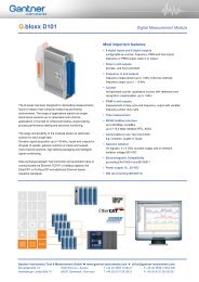
Universal Measurement Module<br />
voltage, current, resistance, potentiometer, Pt100, Pt1000,<br />
thermocouples, measuring bridges, IEPE-sensors<br />
Fast high accuracy digitalization<br />
24 bit ADC, 100 kHz sample rate per channel<br />
1 digital in or output per channel<br />
input: state, tare, memory reset<br />
output: state, alarm, threshold<br />
Signal conditioning<br />
16 virtual channels, linearization, digital filter, average, scaling,<br />
min/max storage, RMS, arithmetic, alarm<br />
TEDS<br />
class 1 and class 2, according IEEE 1451.4<br />
RS485 fieldbus interface<br />
up to 48 Mbps: LocalBus<br />
up to 115.2 kbps: Modbus-RTU, ASCII<br />
Connectable to any Test Controller<br />
e.g. Q.station, Q.gate or Q.pac<br />
Galvanic isolation<br />
channel to channel to power supply and to interface<br />
Isolation voltage 500 VDC<br />
Electromagnetic Compatibility<br />
according EN 61000-4 and EN 55011<br />
Power supply 10…30 VDC<br />
DIN rail mounting (EN 60715)<br />
Gantner Instruments Test & Measurement GmbH www.gantner-instruments.com office@gantner-instruments.com<br />
Silvrettastraße 13 6780 Schruns / Austria T +43 (0) 5556 77463-0 F +43 (0) 5556 77463-300<br />
Heidelberger Landstraße 74 64297 Darmstadt / Germany T +49 (0) 6151 95136-0 F +49 (0) 6151 95136-26
Q.<strong>bloxx</strong> <strong>A101</strong><br />
Block Diagram<br />
Analog Inputs<br />
Number 2<br />
Accuracy 0.01 % typical<br />
0.025 % in controlled environment¹<br />
0.05 % in industrial area²<br />
Linearity error 0.01 % of the final value typical<br />
Repeatability 0.003 % typical (within 24 h)<br />
Isolation voltage 500 VDC channel to channel to power supply to interface 3<br />
Sensor identification TEDS predefined<br />
Universal Measurement Module<br />
Measurement Voltage Range max. Deviation Resolution<br />
±60 V ±0.2 V 7.2 µV<br />
±10 V ±2 mV 1.2 µV<br />
±1 V ±0.2 mV 120 nV<br />
±100 mV ±20 µV 12 nV<br />
Input resistance >10 MΩ (range ±10 V = 1 MΩ; range ±60 V = 3 MΩ)<br />
Long term drift
Q.<strong>bloxx</strong> <strong>A101</strong><br />
Universal Measurement Module<br />
Measurement Resistance / RTD Range max. Deviation Resolution<br />
Resistance, 2-wire 100 kΩ ±100 Ω 12 mΩ<br />
Resistance, 2- and 4-wire* 4 kΩ ±1 Ω 0.5 mΩ<br />
Resistance, 2- and 4-wire* 400 Ω ±0.1 Ω 48 µΩ<br />
Pt100, 2- and 4-wire* -200 up to +850°C ±0.25°C 0.2 m°C<br />
Pt1000, 2- and 4-wire* -200 up to +850°C ±1°C 0.2 m°C<br />
Long term drift
Q.<strong>bloxx</strong> <strong>A101</strong><br />
Analog/Digital-Conversion<br />
Digital In/Outputs<br />
Power Supply<br />
Environmental<br />
Communication Interface<br />
Mechanical<br />
Resolution 24 bit<br />
Sample rate 100 kHz (measurement thermocouple 8 Hz)<br />
Conversion method Sigma-Delta (group delay time 380 µs)<br />
Anti-aliasing filter 20 kHz, 5 th order<br />
Universal Measurement Module<br />
Digital filter IIR, low pass, high pass, band pass, 4 th order, 1 Hz up to 10 kHz in steps 1, 2, 5<br />
Averaging configurable or automated according the selected data rate<br />
Number 2 (1 digital I/O per channel)<br />
Response time 0.2 ms<br />
Input state, tare, reset<br />
Input voltage max. 30 VDC<br />
Input current max. 0.5 mA<br />
Upper threshold >10 V (high)<br />
Lower threshold