Q.bloxx D101
Q.bloxx D101
Q.bloxx D101

Create successful ePaper yourself
Turn your PDF publications into a flip-book with our unique Google optimized e-Paper software.
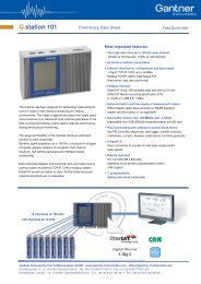
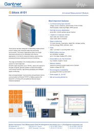
Q.<strong>bloxx</strong> <strong>D101</strong><br />
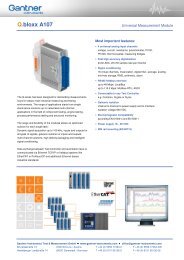
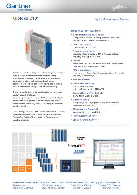
The Q.series has been designed for demanding measurements<br />
found in todays most industrial measuring and testing<br />
environments. The range of applications starts from single<br />
stand-alone solutions up to networked multi-channel<br />
applications in the field of component testing, engine testing,<br />
process performance testing and structural monitoring.<br />
The range and flexibility of the modules allows an optimized<br />
solution for each single task:<br />
Dynamic signal acquisition up to 100 kHz, inputs and outputs for<br />
all types of signals, galvanic isolation of inputs and outputs,<br />
multi-channel solutions, high density packaging and intelligent<br />
signal conditioning.<br />
Data exchange between Test Controller and automation level is<br />
communicated via Ethernet TCP/IP or fieldbus systems like<br />
EtherCAT or Profibus-DP and additional Ethernet-based<br />
industrial standards.<br />
Most important features:<br />
� 8 digital inputs and 8 digital outputs<br />
Digital Measurement Module<br />
configurable as counter, frequency, PWM and time inputs,<br />
frequency or PWM output, state in or output<br />
� State in and outputs<br />
process- and host controlled<br />
� Frequency in and outputs<br />
frequency measurement up to 1 MHz (Chronos method),<br />
frequency output up to 1 / 10 kHz<br />
� Counter<br />
for/backward counter, quadrature counter with reference zero<br />
recognition (reset/enable), up to 1 MHz<br />
� PWM in and outputs<br />
measurement of duty cycle and frequency, output with variable<br />
frequency and/or duty cycle<br />
� Time measurement<br />
� RS485 fieldbus-interface<br />
up to 48 Mbps: LocalBus<br />
up to 115.2 kbps: Modbus-RTU, ASCII<br />
� Connectable to any Test Controller<br />
e.g. Q.station, Q.gate or Q.pac<br />
� Galvanic isolation<br />
I/O-signals ( 4 x 4 I/Os) to power supply and to interface<br />
Isolation voltage 500 VDC<br />
� Electromagnetic Compatibility<br />
according EN 61000-4 and EN 55011<br />
� Power supply 10…30 VDC<br />
� DIN rail mounting (EN 60715)<br />
Gantner Instruments Test & Measurement GmbH ���� www.gantner-instruments.com ���� office@gantner-instruments.com<br />
Silvrettastraße 13 6780 Schruns / Austria T +43 (0) 5556 77463-0 F +43 (0) 5556 77463-300<br />
Heidelberger Landstraße 74 64297 Darmstadt / Germany T +49 (0) 6151 95136-0 F +49 (0) 6151 95136-26
Q.<strong>bloxx</strong> <strong>D101</strong><br />
Digital Inputs<br />
Function<br />
Number 8<br />
Input voltage max. 30 VDC<br />
Input current max. 2 mA<br />
Threshold (programmable) TTL or<br />
Signal voltage „0“ -3… 5 VDC (EN61131-2, Type1)<br />
Signal voltage „1“ 11… 30 VDC (EN61131-2, Type1)<br />
Isolation Voltage 500 VDC group/group and against power supply and interface 1<br />
State<br />
Reaction time 10 µs<br />
Frequency measurement<br />
Digital Measurement Module<br />
8-fold Bit-Set specification such as simple state-input, but the binary coded information of 8 inputs can be<br />
transmitted as a single variable. This functionality covers all 8 inputs even if they are already used<br />
by other functionalities such as counter or frequency measurement. In case of a conflict the Bit-<br />
Set is lower prior<br />
Method Chronos<br />
optimized by combination of time measurement and pulse counting<br />
Recognition of the direction of rotation (0°, 90°)<br />
Frequency range 0.1 Hz up to 1 MHz<br />
Time base 0.001 up to 10 s<br />
Counter frequency (reference) 48 MHz<br />
Frequency measurement with<br />
recognition ot the direction of rotation<br />
PWM measurement<br />
Resolution 0.002 %<br />
specification like frequency measurement. For the recognition of the direction of rotation the<br />
phasing of both inputs is being used.<br />
Input frequency 0.1 Hz up to 1 MHz<br />
Resolution 21 ns<br />
Configuration of the measurement type counter for duty cycle, frequency<br />
Counter<br />
Counter 32 bit (±31 bit)<br />
Counter frequency 1 MHz<br />
Back/forward counter specification like counter but with an additional input fort he direction of counting<br />
Quadrature counter specification like counter. For the recognition of the direction the phasing of both inputs is being<br />
Quadrature counter with zero<br />
reference and reset/enable<br />
Time measurement<br />
used.<br />
specification like quadrature counter but with an additional input for the „0“ reference recognition<br />
and an additional input to activate the counter functionality individually.<br />
Function Measuring of time between two edges, measuring of high time, low time and high/low relation<br />
Time range 1 µs up to 32 s<br />
Resolution 21 ns<br />
1 Noise pulses up to 1000 VDC, permanent up to 250 VDC<br />
Gantner Instruments Test & Measurement GmbH ���� www.gantner-instruments.com ���� office@gantner-instruments.com<br />
Silvrettastraße 13 6780 Schruns / Austria T +43 (0) 5556 77463-0 F +43 (0) 5556 77463-300<br />
Heidelberger Landstraße 74 64297 Darmstadt / Germany T +49 (0) 6151 95136-0 F +49 (0) 6151 95136-26
Q.<strong>bloxx</strong> <strong>D101</strong><br />
Digital Measurement Module<br />
With a Q.<strong>bloxx</strong> <strong>D101</strong> 2 x 4 connectors for digital inputs are available. Those will accept all mentioned signals as it is required. The following<br />
combinations are possible<br />
Connector 1 Connector 2<br />
Terminal 1.6 Terminal 1.7 Terminal 1.8 Terminal 1.9 Terminal 2.6 Terminal 2.7 Terminal 2.8 Terminal 2.9<br />
State State State State State State State State<br />
State State State State State State 2 channel signal 1)<br />
State State State State 2 channel signal 1) 2 channel signal 1)<br />
State State State State 4 channel signal 2)<br />
State State 2 channel signal 1) 2 channel signal 1) 2 channel signal 1)<br />
State State 2 channel signal 1) 4 channel signal 2)<br />
2 channel signal 1) 2 channel signal 1) 4 channel signal 2)<br />
2 channel signal 1) 2 channel signal 1) 2 channel signal 1) 2 channel signal 1)<br />
4 channel signal 2) 4 channel signal 2)<br />
1) all digital input functionalities except state and „quadrature counter<br />
with reference zero and reset/enable“<br />
Digital Outputs<br />
Function<br />
Number 8<br />
Contact open drain p-channel MOSFET (short circuit proof)<br />
Load 30 VDC/500 mA (ohmic Load)<br />
State<br />
Reaction time<br />
(depending on load)<br />
2) Quadrature counter with reference zero and reset/enable<br />
>0,5 A >0,1 A
Q.<strong>bloxx</strong> <strong>D101</strong><br />
Power Supply<br />
Environmental<br />
Communication Interface<br />
Mechanical<br />
Power supply 10 up to 30 VDC, overvoltage and overload protection<br />
Power consumption approx. 2 W<br />
Influence of the voltage