photoelectric sensors ft18m series 10 ÷ 30 vdc
photoelectric sensors ft18m series 10 ÷ 30 vdc
photoelectric sensors ft18m series 10 ÷ 30 vdc

You also want an ePaper? Increase the reach of your titles
YUMPU automatically turns print PDFs into web optimized ePapers that Google loves.
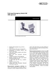
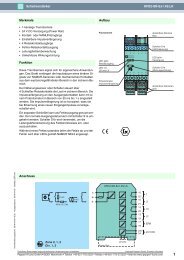
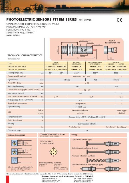
PHOTOELECTRIC SENSORS FT18M SERIES <strong>10</strong> <strong>÷</strong> <strong>30</strong> VDC<br />
STAINLESS STEEL CYLINDRICAL HOUSING M18x1<br />
PROGRAMMABLE OUTPUT NPN/PNP<br />
FUNCTIONS NO + NC<br />
SENSITIVITY ADJUSTMENT<br />
AXIAL BEAM<br />
TECHNICAL CHARACTERISTICS<br />
Dimensions mm<br />
TYPE<br />
MODEL WITH CABLE<br />
MODEL WITH H PLUG<br />
Sensing range (Sn)<br />
cm<br />
Programmable output<br />
Light source<br />
Led<br />
Power ON delay<br />
mSec<br />
Switching frequency<br />
Hz<br />
Continuous voltage (Res. ripple ≤<strong>10</strong>%) V<br />
Max output current<br />
mA<br />
Max current consumption at 24 Vdc mA<br />
Voltage drop (I out = 200 mA)<br />
V<br />
Short circuit protection<br />
Light immunity<br />
LED<br />
Temperature limit<br />
Protection degree<br />
Housing<br />
Cable<br />
Connector plug<br />
WIRING DIAGRAMS<br />
PNP<br />
P N<br />
NPN<br />
P N<br />
EMITTER<br />
<strong>10</strong> <strong>÷</strong> <strong>30</strong><br />
Vdc<br />
BROWN<br />
WHITE<br />
BLACK<br />
BLUE<br />
BROWN<br />
WHITE<br />
BLACK<br />
BLUE<br />
BROWN<br />
BLUE<br />
N.C.<br />
N.O.<br />
N.C.<br />
N.O.<br />
N.B.: On request is available cable for<br />
<strong>sensors</strong> with different length<br />
3.5 - 5 - 7.5 - <strong>10</strong> m.<br />
Yellow<br />
Green<br />
°C<br />
IP<br />
2m<br />
FT18M-CP2 FT18M-CP4 FT18M-CR<br />
FT18M-CP2-H FT18M-CP4-H FT18M-CR-H<br />
20* 40*<br />
250**<br />
VIEW OF MALE<br />
CONNECTOR H<br />
1<br />
4<br />
2<br />
M18 x 1<br />
DIRECT<br />
REFLECTION<br />
≤ 50<br />
CONNECTION WHIT H PLUG<br />
FOR CONNECTORS SEE PAGE 85<br />
2 WIRINGS (EMITTER)<br />
1 = Brown / +<br />
3 = Blue / --<br />
3<br />
37<br />
Infrared<br />
4 WIRINGS<br />
1 = Brown / +<br />
3 = Blue / --<br />
4 = Black / output NO<br />
2 = White / output NC<br />
72<br />
REFLECTION<br />
WITH REFLECTOR<br />
NPN/PNP<br />
700<br />
Sensitivity adjustment<br />
Stability LED<br />
Output LED<br />
Switch<br />
NPN/PNP<br />
200<br />
≤ 3<br />
Incorporated<br />
> <strong>10</strong>.000 Lux<br />
NO + NC<br />
≤ 75<br />
<strong>10</strong> <strong>÷</strong> <strong>30</strong><br />
Operation indicator<br />
Stability<br />
<strong>10</strong><br />
POLARIZED REFLECTION<br />
WITH REFLECTOR<br />
FT18M-CAR<br />
FT18M-CAR-H<br />
<strong>10</strong>0**<br />
Storage -20 <strong>÷</strong> +90°C • Working -20 <strong>÷</strong> +50°C<br />
4 x 0.25 mm 2<br />
TYPES<br />
67<br />
Stainless steel AISI <strong>30</strong>3<br />
H<br />
≤ 20<br />
Direct reflection (P type)<br />
Red<br />
Reflection with reflector (R type)<br />
Polarized reflection (AR type)<br />
Thru beam emitter + receiver (B type)<br />
*The sensing distance is related to matt white paper dim. <strong>10</strong> x <strong>10</strong> cm. **The sensing distance is related to CT80 reflector.<br />
PLUG H<br />
FOR CONNECTOR<br />
15<br />
M12<br />
THRU BEAM<br />
RECEIVER EMITTER<br />
FT18M-CBR FT18M-CBE<br />
FT18M-CBR-H FT18M-CBE-H<br />
1500<br />
4 x 0,25 mm 2<br />
Infrared<br />
250<br />
-<br />
-<br />
≤ 35<br />
-<br />
-<br />
-<br />
Power supply<br />
(Red led)<br />
2 x 0,50 mm 2
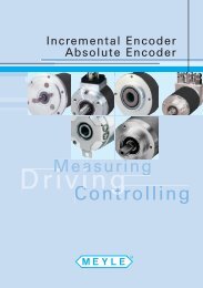
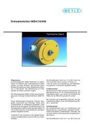
PHOTOELECTRIC SENSORS FT18M SERIES 90° BEAM <strong>10</strong> <strong>÷</strong> <strong>30</strong> VDC<br />
STAINLESS STEEL CYLINDRICAL HOUSING M18x1<br />
PROGRAMMABLE OUTPUT NPN/PNP<br />
FUNCTIONS NO + NC<br />
SENSITIVITY ADJUSTMENT<br />
90° BEAM<br />
25<br />
DIRECT<br />
REFLECTION<br />
FT18M-CP4-90<br />
36<br />
Sensitivity adjustment Switch NPN / PNP<br />
90<br />
REFLECTION<br />
WITH REFLECTOR<br />
Stability LED<br />
Output LED<br />
POLARIZED REFLECTION<br />
WITH REFLECTOR<br />
FT18M-CP2-90<br />
FT18M-CR-90<br />
FT18M-CAR-90<br />
FT18M-CP2-90-H FT18M-CP4-90-H FT18M-CR-90-H FT18M-CAR-90-H<br />
20* 40*<br />
250**<br />
<strong>10</strong>0**<br />
NPN/PNP NO + NC<br />
Infrared<br />
700<br />
200<br />
Red<br />
≤ 75<br />
<strong>10</strong> <strong>÷</strong> <strong>30</strong><br />
≤ 50<br />
≤ 20<br />
≤ 3<br />
Incorporated<br />
> <strong>10</strong>.000 Lux<br />
Operation indicator<br />
Stability<br />
Storage -20 <strong>÷</strong> +90°C • Working -20 <strong>÷</strong> +50°<br />
67<br />
Stainless steel AISI <strong>30</strong>3<br />
4 x 0,25 mm2 NPN<br />
PNP<br />
H<br />
PLUG H<br />
FOR CONNECTOR<br />
<strong>10</strong> 15<br />
FT18M-CBR-90<br />
FT18M-CBR-90-H<br />
M12<br />
THRU BEAM<br />
RECEIVER EMITTER<br />
4 x 0,25 mm 2<br />
1500<br />
Infrared<br />
250<br />
FT18M-CBE-90<br />
FT18M-CBE-90-H<br />
-<br />
-<br />
≤ 35<br />
-<br />
-<br />
-<br />
Power supply<br />
(Red led)<br />
2 x 0,50 mm 2<br />
INSTRUCTIONS FOR THE PROGRAMMING AND ADJUSTMENT EMITTER FT18M-CBE<br />
TRIMMER FOR THE SENSING RANGE ADJUSTMENT: The photocell is supplied with max. sensing range<br />
with the trimmer totally rotated in the clockwise direction. The sensitivity reduces by rotating the trimmer<br />
in the anti-clockwise direction.<br />
SWITCH NPN/PNP: The photocell is supplied with the switch in P (PNP output). To change to NPN<br />
turn the switch to N in the anti-clockwise direction.<br />
WARNING! For a correct working of the unit, do not carry out the switching when the photocell is<br />
powered.<br />
GREEN LED - STABILITY INDICATOR: This led is on when the level of the output signal and the alignment<br />
of the <strong>photoelectric</strong> <strong>sensors</strong> are in the optimum position.<br />
In the case that the led is off this indicates that the lens is obscured or for the types with direct reflection<br />
a possible alteration of the dimension or color of the object to be detected.<br />
YELLOW LED - OPERATION INDICATOR: This led is on when the object to be detected enters the<br />
sensing range of the photocell giving output signals.<br />
NOTE! Before giving a power supply to the photocell it is recommended that the same<br />
unit be programmed by using the switch in the required function NPN or PNP.<br />
NOTE! It is recommended that the trimmer and the switch be rotated very carefully by using a proper tool otherwise these can be seriously damaged.<br />
POWER SUPPLY<br />
LED POSITION<br />
RED LED<br />
TYPES WITH CABLE<br />
RED LED X 4<br />
TYPES WITH CONNECTOR<br />
®<br />
PHOTOELECTRIC
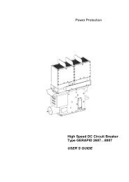
PHOTOELECTRIC SENSORS FT18 SERIES 20 <strong>÷</strong> 250 VAC<br />
CYLINDRICAL HOUSING M18x1<br />
3 WIRES A.C.<br />
PROGRAMMABLE OUTPUT NO/NC<br />
SENSITIVITY ADJUSTMENT<br />
AXIAL BEAM<br />
TECHNICAL CHARACTERISTICS<br />
Dimensions mm<br />
TYPE<br />
MODEL WITH CABLE<br />
MODEL WITH H PLUG<br />
Sensing range (Sn)<br />
Programmable output<br />
Light source<br />
Power ON delay<br />
Switching frequency<br />
Alternating voltage 50 <strong>÷</strong> 60 Hz<br />
Max output current<br />
Max peak current for 20 ms<br />
Max current consumption<br />
Voltage drop (Sensor ON) (Max)<br />
Short circuit protection<br />
Light immunity<br />
Led<br />
Temperature limit<br />
Protection degree<br />
Plastic housing<br />
Cable<br />
Connector plug<br />
WIRING DIAGRAMS<br />
NO NC<br />
NO<br />
NO NC<br />
NC<br />
BROWN<br />
WHITE<br />
BLUE<br />
BROWN<br />
WHITE<br />
BLUE<br />
L1<br />
N<br />
L1<br />
N.B.: On request is available cable for<br />
<strong>sensors</strong> with different length<br />
3.5 - 5 - 7.5 - <strong>10</strong> m.<br />
N<br />
cm<br />
Led<br />
mSec<br />
Hz<br />
V<br />
mA<br />
A<br />
mA<br />
V<br />
°C<br />
IP<br />
2m<br />
FT18-AP2<br />
FT18-AP2-H FT18-AP4-H FT18-AR-H FT18-AAR-H FT18-ABR-H FT18-ABE-H<br />
20* 40*<br />
250** <strong>10</strong>0**<br />
1500<br />
CONNECTIONS WITH H PLUG<br />
FOR CONNECTORS SEE PAGE 85<br />
VIEW OF MALE<br />
CONNECTOR H<br />
EMITTER<br />
BROWN<br />
L1<br />
2 WIRINGS (EMITTER)<br />
20 <strong>÷</strong> 250<br />
1 = L1<br />
Vac BLUE<br />
N<br />
3 = N<br />
1<br />
4<br />
2<br />
3<br />
M18 x 1<br />
DIRECT<br />
REFLECTION<br />
FT18-AP4<br />
Infrared<br />
4 WIRINGS<br />
1 = Brown / L1<br />
3 = Blue / N<br />
4 = White / NO - NC<br />
Programmable<br />
N.B.: Use female connector without led.<br />
45<br />
REFLECTION<br />
WITH REFLECTOR<br />
FT18-AR<br />
Sensitivity adjustment<br />
Switch<br />
NO/NC<br />
72 <strong>10</strong><br />
≤ 75<br />
20 <strong>÷</strong> 250<br />
≤<strong>10</strong><br />
FT18-AAR<br />
LED<br />
POLARIZED REFLECTION<br />
WITH REFLECTOR<br />
Storage -20 <strong>÷</strong> +90°C • Working -20 <strong>÷</strong> +50°C<br />
67<br />
Gray makrolon (On request stainless steel AISI <strong>30</strong>3)<br />
TYPES<br />
NO or NC<br />
H<br />
Direct reflection (P type)<br />
Red<br />
Reflection with reflector (R type)<br />
Polarized reflection with reflector (AR type)<br />
Thru beam emitter + receiver (B type)<br />
*The sensing distance is related to matt white paper dim. <strong>10</strong> x <strong>10</strong> cm. **The sensing distance is related to CT80 reflector.<br />
15<br />
<strong>30</strong>0<br />
3<br />
1.5<br />
Incorporated<br />
> <strong>10</strong>.000 Lux<br />
Operation indicator<br />
3 x 0.35 mm 2<br />
PLUG H<br />
FOR CONNECTOR<br />
LED<br />
13<br />
THRU BEAM<br />
RECEIVER EMITTER<br />
FT18-ABR<br />
Infrared<br />
FT18-ABE<br />
-<br />
-<br />
-<br />
-<br />
-<br />
-<br />
-<br />
Power supply<br />
2 x 0,50 mm 2
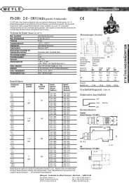
PHOTOELECTRIC SENSORS FT18 SERIES 90° BEAM 20 <strong>÷</strong> 250 VAC<br />
CYLINDRICAL HOUSING M18x1<br />
3 WIRES A.C.<br />
PROGRAMMABLE OUTPUT NO/NC<br />
SENSITIVITY ADJUSTMENT<br />
90° BEAM<br />
25<br />
DIRECT<br />
REFLECTION<br />
FT18-AP4-90<br />
45<br />
REFLECTION<br />
WITH REFLECTOR<br />
Sensitivity adjustment<br />
Switch NO/NC<br />
90 <strong>10</strong><br />
LED<br />
POLARIZED REFLECTION<br />
WITH REFLECTOR<br />
PLUG H<br />
FOR CONNECTOR<br />
LED<br />
13<br />
THRU BEAM<br />
RECEIVER EMITTER<br />
FT18-AP2-90<br />
FT18-AR-90<br />
FT18-AAR-90 FT18-ABR-90 FT18-ABE-90<br />
FT18-AP2-90-H FT18-AP4-90-H FT18-AR-90-H<br />
FT18-AAR-90-H FT18-ABR-90-H FT18-ABE-90-H<br />
20* 40*<br />
250** <strong>10</strong>0**<br />
1500<br />
-<br />
Red<br />
Infrared<br />
-<br />
-<br />
-<br />
-<br />
-<br />
-<br />
Power supply<br />
2 x 0,50 mm2 NO or NC<br />
Infrared<br />
≤ 75<br />
15<br />
20 <strong>÷</strong> 250<br />
<strong>30</strong>0<br />
3<br />
≤ <strong>10</strong><br />
1.5<br />
Incorporated<br />
> <strong>10</strong>.000 Lux<br />
Operation indicator<br />
Storage -20 <strong>÷</strong> +90°C • Working -20 <strong>÷</strong> +50°C<br />
67<br />
Gray makrolon (On request stainless steel AISI <strong>30</strong>3)<br />
3 x 0.35 mm2 INSTRUCTIONS FOR THE PROGRAMMING AND ADJUSTMENT<br />
H<br />
TRIMMER FOR THE SENSING RANGE ADJUSTMENT: The photocell is supplied with max.<br />
sensing range with the trimmer totally rotated in the clockwise direction.<br />
The sensitivity reduces by rotating the trimmer in the anti-clockwise direction.<br />
SWITCH NO/NC: The photocell is supplied with switch in NO position (in absence of the object<br />
to be detected the output is disactivated).<br />
To change to N.C. (in absence of the object to be sensed the output is actived) turn the switch<br />
to N.C. in the anti-clockwise direction.<br />
LED FOR INDICATION OF OPERATION: This indicates the output of the photocell, in the<br />
absence of the object to be sensed it is off with output N.O. and is on with output N.C. this<br />
changes state when the object to be sensed enters into the sensing area of the photocell.<br />
NOTE! Before giving a power supply to the photocell it is recommended that the same unit<br />
be programmed by using the switch in the required function NO or NC.<br />
NOTE! It is recommended that the trimmer and the switch be rotated very carefully by using a proper tool otherwise these can be seriously damaged.<br />
EMITTER FT18-ABE<br />
POSITION OF POWER SUPPLY<br />
LED<br />
TYPES WITH CABLE<br />
LED<br />
LED<br />
TYPES WITH CONNECTOR<br />
®<br />
PHOTOELECTRIC