conveyor belts for - MEYER Industrie-Electronic GmbH
conveyor belts for - MEYER Industrie-Electronic GmbH
conveyor belts for - MEYER Industrie-Electronic GmbH

Create successful ePaper yourself
Turn your PDF publications into a flip-book with our unique Google optimized e-Paper software.
Catalogue<br />
Safety equipments<br />
<strong>for</strong><br />
<strong>conveyor</strong> <strong>belts</strong>
. . . three<br />
companies,<br />
one service . . .<br />
IHM<br />
INGENIEURBÜRO<br />
HERBERT <strong>MEYER</strong><br />
Systems <strong>for</strong> the Automation Industry<br />
<strong>MEYER</strong> INDUSTRIE-<br />
ELECTRONIC GMBH<br />
Components <strong>for</strong> the Automation Industry<br />
INGENIEURGESELLSCHAFT<br />
SACHVERSTÄNDIGER<br />
REVISIONSINGENIEURE MBH<br />
Inspection Company <strong>for</strong> Quality<br />
Assurance<br />
System Integrator and Engineering<br />
company <strong>for</strong> applications and systems<br />
Distribution of a wide range of components<br />
<strong>for</strong> the automation-, process-, machine<br />
building- and manufacturing industries<br />
Certified test laboratory <strong>for</strong> medical<br />
equipment and commercial building<br />
safety and quality tests
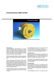
Rotation Rotation Speed Speed Speed Monitor<br />
Monitor<br />
Type Type Al-Ni Al-Ni 6<br />
6<br />
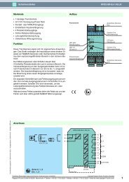
General General<br />
General<br />
The Al-Ni 6 is <strong>for</strong> attachment to the shaft end<br />
of large machines or motors to monitor their<br />
running up, reaching the nominal speed and<br />
stopping at braking. Monitoring of <strong>conveyor</strong><br />
<strong>belts</strong> is possible by rolling wheels.<br />
The Al-Ni 6 is the successor of the proven Al-Ni<br />
5.<br />
It’s dimensions at clutch flange and size have<br />
been maintained from it’s predecessor and the<br />
function principle is compatible. With respect<br />
to the lower switching power the Al-Ni 6 is appropriate<br />
<strong>for</strong> monitoring slow-down, revolution<br />
and <strong>conveyor</strong> <strong>belts</strong>.<br />
As an advantage the Al-Ni 6 features a digital<br />
adjustment of the switching speed (r.p.m.) by<br />
Technical Data<br />
Operation instructions<br />
code switches. The adjustment range is from 60<br />
r.p.m. up to 6000 r.p.m. (1-100 revolutions per<br />
second) in steps of 60 r.p.m. and can be set independently<br />
<strong>for</strong> left and right turning.<br />
Function Function Function Principle<br />
Principle<br />
When the shaft is turned a stepper motor<br />
induces the supply power <strong>for</strong> the signal<br />
processing circuits and the signal voltages <strong>for</strong><br />
determination of revolution and direction.<br />
When the speed selected by the code switches<br />
is reached relay 1 switches at left turning and<br />
relay 2 switches at right turning.<br />
Switching Switching Speed<br />
Speed<br />
For adjustment of the switching speed the<br />
coding switches, two <strong>for</strong> each turning<br />
direction, are to be set by a small screw driver.
The digits 01 to 99 can be adjusted directly, the<br />
adjustment 00 is interpreted to 100 revolutions<br />
per seconds.<br />
The switching hysteresis is<br />
30 - 60 r.p.m. (0,5 - 1 revolutions per second).<br />
Switching Switching Per<strong>for</strong>mance<br />
Per<strong>for</strong>mance<br />
The switching per<strong>for</strong>mance is determined by<br />
the contacts of the bistable bistable relay. The max.<br />
values <strong>for</strong> voltage, current and switching<br />
power (resistive) are given in the following<br />
table.<br />
Switching Switching Per<strong>for</strong>mance<br />
Per<strong>for</strong>mance<br />
max. voltage 400V AC 240V DC<br />
max. current 5A 5A<br />
Technical Technical Data Data<br />
Data<br />
Mechanical Mechanical Mechanical Data<br />
Data<br />
Procurement Procurement Data Data<br />
Data<br />
max. switching power 1250VA 150W<br />
Connecting Connecting Ports<br />
Ports<br />
The connecting ports are suitable <strong>for</strong> wires up<br />
to 2.5 mm˛ . For insertion of the wires the cage<br />
clamp must be opened by the by-packed tool<br />
or alternatively by pressing with a suitable<br />
screw driver from the front or rear side. The<br />
connecting port allocation is given in Fig. 2.<br />
Warning<br />
Warning<br />
Hazardous voltage may appear at the electrical<br />
ports even when the device has stopped. There<strong>for</strong>e,<br />
the power supply must be switched off<br />
prior to opening the device. Entrance of humidity<br />
into the opened device must be<br />
avoided.<br />
Supply voltage: Internally generated<br />
Nominal speed range: 60 to 6.000 r.p.m.<br />
(1 to 1.00 r.p.s.)<br />
Relay contacts: 2 alternators, <strong>for</strong> left and right<br />
turning<br />
Switching per<strong>for</strong>mance: max. 400V AC, 5A, 1250VA<br />
max. 240V DC, 5A, 150W<br />
(resistive)<br />
Adaptation: Pin adapter with plugged<br />
elastic clutch<br />
Cable entry: PG 16, <strong>for</strong> cable ř 7 to 12 mm<br />
Housing material: Glass fibre rein<strong>for</strong>ced plastic;<br />
oil, grease and acid resistant<br />
Housing dimensions: According to fig. 1<br />
Flange diameter: 120 mm<br />
Shaft bearing: 2 ball bearings<br />
Environmental temperature: Operating -25°...+70°C<br />
Storage -40°...+80°C<br />
Transport -40°...+80°C<br />
Enclosure: IP 65<br />
Rotation speed monitor Al-Ni 6 Ident.No.: AS999<br />
Elastic clutch Ident.No.: AS996
Testing Testing and and Qualification Qualification of of of the the Item<br />
Item<br />
Humidity: DIN IEC 68-2-30<br />
Lower temp.: +25°C / 97% rel. hum.<br />
Upper temp.: +55°C / 93% rel. hum.<br />
Test duration: 6 days<br />
Vibration: DIN EN 60 068 -2 -6<br />
Frequency: 10 - 150Hz<br />
Amplitude: 0,35mm<br />
Resp. acceleration: 5g (20 Cycles per axis)<br />
Shock loads: DIN EN 60 068 -2 -27<br />
Shocktype: semi-sine<br />
Amplitude: 30g<br />
Duration: 18ms (3 Shocks per orientation)<br />
Long term shock loads: DIN EN 60 068 -2 -29<br />
Shocktype: semi-sine<br />
Amplitude: 25g<br />
Duration: 6ms (1000 Shocks per orientation)<br />
Isolation: DIN / VDE 0435 Part 303<br />
Check value: 2kV AC<br />
Susceptibility: Conducted susc.: DIN / EN 50141 10 V<br />
Radiated susc.: DIN ENV 50140 10 V/m<br />
Electrostatic discharge: DIN EN 61 000-4-8<br />
Contact 4 kV<br />
Air gap 8 kV<br />
Burst: DIN EN 61 000-4-4 2 kV<br />
Surge: DIN EN 61 000-4-5<br />
asymmetrical 4 kV<br />
symmetrical 2 kV<br />
Emission: Radiated emission: DIN EN 55 022 Line B<br />
Fig. 1: Dimensions
Fig. 2 : Function of the code switches and location of the connecting ports<br />
Relation Relation of of of code code switches switches position position and and switching switching speed<br />
speed<br />
06.424/0698 (Subject to alteration)<br />
Example:<br />
Example:<br />
Switching speed<br />
at 2340 U/min,<br />
turning direction right =<br />
switching position 3 : 9,<br />
on the right switches<br />
Pos. r.p.s. r.p.m. Pos. r.p.s. r.p.m. Pos. r.p.s. r.p.m. Pos. r.p.s. r.p.m. Pos. r.p.s. r.p.m.<br />
0 : 1 1 60 2 : 1 21 1260 4 : 1 41 2460 6 : 1 61 3660 8 : 1 81 4860<br />
0 : 2 2 120 2 : 2 22 1320 4 : 2 42 2520 6 : 2 62 3720 8 : 2 82 4920<br />
0 : 3 3 180 2 : 3 23 1380 4 : 3 43 2580 6 : 3 63 3780 8 : 3 83 4980<br />
0 : 4 4 240 2 : 4 24 1440 4 : 4 44 2640 6 : 4 64 3840 8 : 4 84 5040<br />
0 : 5 5 300 2 : 5 25 1500 4 : 5 45 2700 6 : 5 65 3900 8 : 5 85 5100<br />
0 : 6 6 360 2 : 6 26 1560 4 : 6 46 2760 6 : 6 66 3960 8 : 6 86 5160<br />
0 : 7 7 420 2 : 7 27 1620 4 : 7 47 2820 6 : 7 67 4020 8 : 7 87 5220<br />
0 : 8 8 480 2 : 8 28 1680 4 : 8 48 2880 6 : 8 68 4080 8 : 8 88 5280<br />
0 : 9 9 540 2 : 9 29 1740 4 : 9 49 2940 6 : 9 69 4140 8 : 9 89 5340<br />
1 : 0 10 600 3 : 0 30 1800 5 : 0 50 3000 7 : 0 70 4200 9 : 0 90 5400<br />
1 : 1 11 660 3 : 1 31 1860 5 : 1 51 3060 7 : 1 71 4260 9 : 1 91 5460<br />
1 : 2 12 720 3 : 2 32 1920 5 : 2 52 3120 7 : 2 72 4320 9 : 2 92 5520<br />
1 : 3 13 780 3 : 3 33 1980 5 : 3 53 3180 7 : 3 73 4380 9 : 3 93 5580<br />
1 : 4 14 840 3 : 4 34 2040 5 : 4 54 3240 7 : 4 74 4440 9 : 4 94 5640<br />
1 : 5 15 900 3 : 5 35 2100 5 : 5 55 3300 7 : 5 75 4500 9 : 5 95 5700<br />
1 : 6 16 960 3 : 6 36 2160 5 : 6 56 3360 7 : 6 76 4560 9 : 6 96 5760<br />
1 : 7 17 1020 3 : 7 37 2220 5 : 7 57 3420 7 : 7 77 4620 9 : 7 97 5820<br />
1 : 8 18 1080 3 : 8 38 2280 5 : 8 58 3480 7 : 8 78 4680 9 : 8 98 5880<br />
1 : 9 19 1140 3 : 9 39 2340 5 : 9 59 3540 7 : 9 79 4740 9 : 9 99 5940<br />
2 : 0 20 1200 4 : 0 40 2400 6 : 0 60 3600 8 : 0 80 4800 0 : 0 100 6000<br />
Meyer <strong>Industrie</strong>-<strong>Electronic</strong> <strong>GmbH</strong><br />
Carl-Bosch-Straße 8<br />
49525 Lengerich<br />
Tel. (+ 49 54 81) 93 85 - 0<br />
Fax (+ 49 54 81) 93 85 - 12<br />
EMail: sales@meyle.de<br />
Address
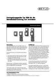
Conveyor belt speed monitor<br />
Type BWA<br />
Application<br />
Our <strong>conveyor</strong> belt speed control<br />
switch BWA is an electromechanical<br />
device <strong>for</strong> electrical<br />
monitoring of the speed of any<br />
<strong>conveyor</strong> belt, including the<br />
scheduled running-up of <strong>belts</strong>.<br />
In operation, a roller is pressed<br />
against the lower side of the<br />
<strong>conveyor</strong> belt. As the belt<br />
transverses, a magnetic field is<br />
generated and is dependent on<br />
the speed and direction of travel of<br />
the <strong>conveyor</strong> belt. This action<br />
results in activating the switching<br />
contacts via the inner adjustable<br />
spring and lever mechanism. Per<br />
rotation direction a single circuit<br />
two-way contact is actuated and is<br />
adjustable <strong>for</strong> a given speed<br />
range.<br />
Techcal Data<br />
Each of these contacts can be<br />
individually used to monitor the<br />
running-up or running-down speed.<br />
The switch bearing is an antifriction<br />
bearing allowing <strong>for</strong> maintenancefree<br />
operation. The metal housing of<br />
the switch is of type IP 55<br />
(con<strong>for</strong>ming to the German<br />
standard).<br />
The following executions are<br />
available in order to cater <strong>for</strong><br />
different requirements:<br />
Switch type BWA has its roller in<br />
direct contact to the fixing foot. This<br />
version is designed to be installed<br />
with the roller in contact with the<br />
lower belt adjacent to a support<br />
roller. The displacement <strong>for</strong>ce is<br />
determined by the installation<br />
Technical Data<br />
position.<br />
Switch types BWA 500 and<br />
BWA 750 are equipped with a<br />
movable spring-loaded lever<br />
with lengths of 500mm or<br />
700mm. The switch roller is<br />
designed to be positioned<br />
against the underside of the<br />
upper belt with the springloaded<br />
lever tension. Reliable<br />
switch operation is guaranteed<br />
even if the belt height deviates<br />
by ±30mm.<br />
Different roller diameters are<br />
available <strong>for</strong> the above switches<br />
to con<strong>for</strong>m to different line<br />
speed ranges.
Technical Data<br />
Contacts 1 single circuit two-way per direction<br />
Switch per<strong>for</strong>mance max. 400VAC, 5A 1250VA<br />
max. 240VDC, 5A 140W(at ohmic load)<br />
Cable inlet 1 x Pg 16 threaded hole <strong>for</strong> conduction Ø7-12mm<br />
Fixing 2 holes <strong>for</strong> M12<br />
Type of enclosure IP 65 (con<strong>for</strong>ming to the German standard)<br />
Voltage unnecessary! It is internally generated!<br />
Connection cross-section max. 2.5 mm²<br />
Material roller polyamide lever<br />
thick-walled steel tube<br />
fixing and bearing housingcast iron<br />
wiring space and lid coloured glass fibre<br />
rein<strong>for</strong>ced polyester<br />
Colour Yellow RAL 1004 other colours are optional<br />
Operating temperature -25°C up to +45°C<br />
Dimensioned drawings<br />
Selection table<br />
Type Length of lever Roller Ø<br />
"L" "D" spring<br />
BWA 0/80 145 80<br />
BWA 0/110 145 100<br />
BWA 0/140 145 125<br />
BWA 500/80 500 80 x<br />
BWA 500/110 500 110 x<br />
BWA 500/140 500 140 x<br />
BWA 750/80 750 80 x<br />
BWA 750/110 750 110 x<br />
BWA 750/140 750 140 x<br />
Remark: lower trip speeds of 33% may also be determined whereby the expected exactness reduces to +/- 10%.
Mounting indstructions <strong>for</strong> belt speed monitors of types BWA<br />
Mounting indstructions <strong>for</strong> belt speed monitors of types BWA
06.417/0498 (Subject to alteration)<br />
Meyer <strong>Industrie</strong>-<strong>Electronic</strong> <strong>GmbH</strong><br />
Carl-Bosch-Str. 8, D - 49525 Lengerich<br />
Tel.: +49-5481-9385-0, Fax: +49-5481-9385-12<br />
E-Mail: sales@meyle.de<br />
Internet: http://www.meyle.de<br />
Address
Material flow control switch<br />
Type MFG M / J<br />
Application<br />
Material flow control switches are<br />
provided to be safely installed <strong>for</strong><br />
the automatical operation of<br />
conveying plants. They control the<br />
charge height of the conveying<br />
belt as well as the interruption of<br />
the material flow.<br />
MEYLE material flow control<br />
switches MFG are equipped with a<br />
dragging sheet leaded over the<br />
belt by a joint pipe measuring<br />
around 50 cm long. This dragging<br />
sheet lies on the conveying belt or<br />
on the bulk material due its dead<br />
weight. During the transport of<br />
bulk material on the belt, the<br />
dragging sheet is highly different<br />
Techcal Data<br />
Technical Data<br />
displaced. After having achieved the<br />
displacement height being internally<br />
adjusted, the change-over effects.<br />
For a reliable, maintenance-free<br />
operation, all shafts are ball<br />
beared. The solid steel housing with<br />
the type of enclosure IP65 enables a<br />
high operating field. The dragging<br />
sheet is fastened with only one nut<br />
and, consequently, easy to be<br />
exchanged. It is mountable either <strong>for</strong><br />
left or right direction of belt motion.<br />
Should the dragging sheet be too<br />
heavy <strong>for</strong> your special operation, a<br />
version with an adjustable counter<br />
weight is available. According to your<br />
specification, the material flow<br />
control switch is equipped either with<br />
a proximity switch or with a<br />
micro switch. Both should be in<br />
accordance with the following<br />
selection table. The micro<br />
switches have the advantage to<br />
a direct high switching capacity<br />
and the proximity switches are<br />
distinguished by free wear and a<br />
practically free hysteresis step<br />
back.
Technical Data<br />
Design 1 micro switch or 1 proximity switch<br />
Fixing 2 holes <strong>for</strong> M10-screws<br />
Type of enclosure IP 65 (con<strong>for</strong>ming to the German standard )<br />
Cable inlet <strong>for</strong> micro switch 1 x Pg 16 threaded hole or per adapter 1/2" NPTF<br />
(accessory) and <strong>for</strong> proximity switch brought out cable end<br />
Colour yellow RAL 1003 or other colours on request<br />
Weight 16.0 kg, with counter weight 18.0 kg<br />
Permissible -25°C up to +45°C<br />
operating<br />
temperature<br />
Dimensions of MFG<br />
Selection table<br />
Dragging sheet with<br />
adjustable Counter weight<br />
Dragging sheet<br />
Switch type Counter weight Design<br />
MFGM micro switch<br />
MFGM-G X micro switch<br />
MFG J1 proximity switch 24VDC, 2-wire system<br />
MFG J1-G X proximity switch 24VDC, 2-wire system<br />
MFG J2 proximity switch 48VDC, 2-wire system<br />
MFG J2-G X proximity switch 48VDC, 2-wire system<br />
MFG J3 proximity switch 120VDC, 2-wire system<br />
MFG J3-G X proximity switch 120VDC, 2-wire system
Installation and operating instructions<br />
Material flow control switch MFG M/J<br />
Principle: Be<strong>for</strong>e any work shall be carried out it has to be checked that the whole line is circuit-free and any<br />
specific and general security instruction has been fulfilled.<br />
Material flow control switches of this type are provided to be safely installed <strong>for</strong> the automatical operation of<br />
belt <strong>conveyor</strong>s. They control the charge height of the belt as well as the interruption of the material flow.<br />
MEYLE material flow control switches MFG are equipped with a dragging sheet leaded over the belt by a joint<br />
pipe measuring around 50 cm long. This dragging sheet lies on the conveying belt or on the bulk material due its<br />
dead weight. During the transport of bulk material on the belt, the dragging sheet is highly different displaced.<br />
After having achieved the displacement height being internally adjusted, the change-over effects.<br />
For a reliable, maintenance-free operation, all shafts are ball beared. The solid steel housing with the type of<br />
enclosure IP65 enables a high operating field. The dragging sheet is fastened with only one nut and,<br />
consequently, easy to be exchanged. It is mountable either <strong>for</strong> left or right direction of belt motion.<br />
Mounting: Put the switch on a plane and stable console, whose plane is parallel to the plane of the belt and<br />
approx. 400mm over the height of bulk material being expected. Also adjust the switch in such manner that the<br />
blade slides over the middle of the belt area. Fixing of the switch is to be effected with two suitable screws M12<br />
at the wholes 14 x 30 mm.<br />
Mounting of dragging sheet: Push on the dragging sheet on the shaft and secure with nuts of type M8.<br />
Installation: To allow electrical installation open cover by turning the four slitted hexagonal screws. Now a<br />
switching element with one NO and one NC is to be found. Functions of the contacts are printed on the<br />
switching element. One thread with Pg16-thread is available <strong>for</strong> cable inlet which is provided with brass cable<br />
mount. Wire the contacts and the earthing contact according to the requirements demanded by the line at-site.<br />
Adjustment: Open the lid after loosening the cap screw M6 carry out the adjustment at the switch wafer. Once<br />
finished the adjustment tighten screw. Afterwards put on the cover again and tighten screws.<br />
Check: Please check any electrical and mechanical function after completion of installation.<br />
Maintenance: There is no need of any maintenance works <strong>for</strong> MEYLE material flow control switch due to<br />
prooven construction and high material quality.
06.417/0498 (Subject to alteration)<br />
Meyer <strong>Industrie</strong>-<strong>Electronic</strong> <strong>GmbH</strong><br />
Carl-Bosch-Str. 8, D - 49525 Lengerich<br />
Tel.: +49-5481-9385-0, Fax: +49-5481-9385-12<br />
E-Mail: sales@meyle.de<br />
Internet: http://www.meyle.de<br />
Address
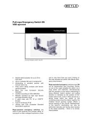
Pull Rope Emergency Switch<br />
Type NSR<br />
VDE approved<br />
Application<br />
According to DIN / VDE 0660 T200 / T210, EN<br />
418, and the general stipulations of the incident<br />
prevention order VB610, devices or entire industrial<br />
machines and installations must be able to be<br />
switched off as quickly as possible by activating<br />
an emergency switch-off device in the case of possible<br />
danger to persons or damages to machines<br />
and installations.<br />
The pull rope emergency switches types NSR (with<br />
<strong>for</strong>k lever) are meeting the standards of DIN / VDE<br />
0660 T200 / T210 and EN418. These switches<br />
must be used in control current circuits only. They<br />
serve as devices to prevent incidents, injuries and<br />
damages to production assets as e.g. <strong>conveyor</strong><br />
<strong>belts</strong> in the iron & steel industry, mineral exploitation<br />
industry, loading & unloading facilities, chemical<br />
industry and mining.<br />
The pull rope emergency switch type NSR including<br />
accessories is <strong>for</strong> installation on the accessible side<br />
of <strong>conveyor</strong> <strong>belts</strong> or machines. It can be activated at<br />
any point of the line surveyed (an advantage over<br />
push-button type emergency switch-off is distributed<br />
in distances over the line to be monitored) and, depending<br />
on the switching logic, deactivate one or<br />
more drives or an entire complex, too.<br />
Technical Data<br />
Configuration and Features<br />
The rope switch consists of a weather proof glass<br />
fibre rein<strong>for</strong>ced plastic housing (yellow RAL 1004)<br />
with enclosure IP65. It is equipped with two holes<br />
<strong>for</strong> leads PG 16 which are plugged <strong>for</strong> shipping (do<br />
not use in operation). The switching mechanism<br />
makes the pull rope emergency switch staying operational<br />
even in case of broken springs.<br />
Its fail safe features correspond to the EN418 and<br />
the recommendations of the trade association:<br />
The pull rope emergency switch locks automatically<br />
and self driven after activation and can be reset<br />
only by the reset lever at the switch. If required,<br />
the reset lever can be made lockable as<br />
well. The item is available with 1, 2, or 3 switching<br />
elements cogently operated by the switching<br />
mechanism. Additionally, a signal lamp can be accommodated<br />
in the cover.<br />
With the pull rope mounted on both sides of the<br />
activation lever a line length of about 100 m (max.<br />
150 m) can be monitored. The switch will be activated<br />
automatically by pre-loading via pull springs<br />
in case of a rope rupture on one side.
Mode Mode of of of Operation<br />
Operation<br />
The pull rope emergency switch type NSR 01/02/<br />
03 is operated by a 50 m (max. 75 m) pull rope<br />
(steel rope, red plastic coated, dia. 5 mm) on<br />
each of the two sides. The triggering of the<br />
mechanism will be caused py pulling the pull<br />
rope.<br />
At an angular deviation from the mid position<br />
of about 6° ± 3° (activation <strong>for</strong>ce = 35 N ± 5 N)<br />
the patented switching mechanism is activated.<br />
This mechanism in turn suddenly activates the<br />
Pull Pull Rope Rope Arrangement, Arrangement, Version Version A<br />
A<br />
Pull Pull Rope Rope Rope Arrangement, Arrangement, Version Version B<br />
B<br />
control switches and cogently guides the<br />
switch lock into end stop position. The activated<br />
(pushed-down) position of the control<br />
switches can be unlocked only by the reset lever.<br />
The control switches feature a cogent separation<br />
characteristic and correspond to the international<br />
safety standard EN418. The NC contact<br />
(normally closed) opens the safety chain of the<br />
control and effects a switch-off of the subsequent<br />
device.<br />
Accessoires:<br />
Accessoires:<br />
1 eye screw M6x60 4 rope eye 3/16" 7 pull rope: steel rope with red PVC sheathing<br />
2 turnbuckle M6x110 5 rope clamp 3/16" diameter 5mm<br />
3 spring RZ 168 6 wire loop M 8 x 80 weight 0,039 kg/m<br />
with bolt tensile strength 1600 N/mm˛<br />
8 spring bridge rope elongation 0,012 mm/m °C<br />
To ensure a safe switch-off when the rope is ruptured, both springs (3) must be pre-loaded to an extent,<br />
that the distance between the eyes amounts at least to 250 mm and the activation lever is in mid position:<br />
a) Rough adjustment at the rope end, b) refinement at the turnbuckle.<br />
distance between supports a [m] 2 2,5 3 3,5 4 5<br />
switching distance s [mm] ca. 280 310 340 360 390 430<br />
Mounting examples (A= without rope rupture protection, B= with rope rupture protection according to VDE 0113)
Technical Technical Data Data<br />
Data<br />
Type<br />
Circuit connection<br />
NSR 01 NSR 02 NSR 03<br />
Switching units 1 x S 826 e 2 x S 826 e 3 x S 826 e<br />
Switching per<strong>for</strong>mance 400 V ~ cos ϕ = 1/0,4 3 A / 2 A 0,5 x 10 6 switchings<br />
230 V ~ cos ϕ = 1/0,4 3,7 A / 2,1 A 0,5 x 10 6 switchings<br />
80 V - τ = 0 ms 4,4 A 0,5 x 10 6 switchings<br />
24 V - τ = 0 ms 10 A 0,5 x 10 6 switchings<br />
Duration current Ith2 Switching capability <strong>for</strong> VDE-classification AC 15<br />
10 A<br />
1A / 230 V<br />
Switching capability <strong>for</strong> VDE-classification DC 13 0,5 A / 110 V<br />
Switching contact material hard silver<br />
(gold plated switching contacts available <strong>for</strong> low<br />
voltage operation)<br />
Switching contact gap 1,6 mm<br />
Mechanical durability (switching element) 1 x 10⁷ switchings<br />
Activation velocity > 0,5 mm/s<br />
Dimensioned nominal insulation voltage 400 V<br />
Insulation class VDE 0110 C<br />
Connecting Ports 0,75 to max. 2,5 mm˛<br />
Short cut protection required (fuse) 10 A<br />
Specifications met DIN VDE 0660, Part 200 and 210, i.e. IEC 947-5-1<br />
VDE 0110<br />
UVV - VBG 10<br />
EN 418, IEC 529<br />
Application Devices and controls to VDE 0100 and 0113<br />
Housing GFK (Glass fibre rein<strong>for</strong>ced plastic),<br />
resistant against water solutions of<br />
salts, acids, and alkalines, alcohol and solvents.<br />
Colour Housing: yellow, RAL 1004<br />
Operation and reset lever: red, RAL 3000<br />
Weight 1kg approx.<br />
Enclosure (according to DIN 40050) IP 65<br />
Installation orientation Preferably upright, i.e. activation lever up<br />
Mechanical durability of device 1 x 10 5 switchings<br />
Attachment to the operation lever Bolt, ř 8mm<br />
stainless<br />
Cable routing Threaded holes, 2 x PG16<br />
Ground connection in housing<br />
Permissible environment temperature Storage -40°C...+85°C<br />
Operation -40°C...+85°C<br />
Transport -40°C...+85°C<br />
Switching angle 6° ±3°<br />
Activation angle 15° +3°<br />
Activation <strong>for</strong>ce 35 N ±5 N<br />
Switching principle Snap switch with activation cam, cogently separated<br />
max. equipment 3 circuit openers and 3 circuit closers<br />
(with signal lamp max. 3 circuit openers and 2 circuit closers)<br />
Signal lamp (Option) 24, 42-220 V B15D<br />
max. 5 W<br />
Special accessory Gold plated switching contacts<br />
(low voltage operation)<br />
Exchange with predecessor NSR 11/12/13 By adapter plate the NSR 11/12/13 can be mounted on the<br />
attachment flanges with the holes arrangement<br />
of the predecessor NSR 11/12/13
Safety Instructions<br />
• The plugs are only <strong>for</strong> dirt protection, they are not<br />
<strong>for</strong> use in operation<br />
PG-screwings must be sealed with an o-ring<br />
against the housing<br />
PG-screwings witch are not in use must be closed<br />
by a plug and sealing<br />
The inner cabeling must be routed in a way that a<br />
single wire cannot fall into the mechanical<br />
arrangement in case of a becoming loose. This is<br />
preferabely achieved by cable binders holding<br />
together all single wire.<br />
The following must be inspected periodically during<br />
operation of a pull rope type emergency switch-off<br />
device:<br />
Safe attachment of the emergency switch-off<br />
device<br />
Tightness of the switch cover<br />
Cleanliness of device (wire, rope, marking) <strong>for</strong><br />
easy recognition<br />
Damage freedom of wire or rope from wear,<br />
corrosion, or impact<br />
Sufficient tightness of wire or rope<br />
Absence of signs <strong>for</strong> damage (cracks, corrosion,<br />
de<strong>for</strong>mation) at switch<br />
Damage freedom and tightness of rope<br />
attachment devices<br />
Proper and safe attachment of pre-loading springs<br />
Dimensions NSR<br />
06.474/022001 (Subject to alteration)<br />
Damage freedom and cleanliness of guidance<br />
loops<br />
Cleanliness and release of rope supporting<br />
wheels<br />
Absence of <strong>for</strong>eign particles in influences<br />
collected at the device which could obstruct<br />
activation parts<br />
Absence of obstacles near the wire or rope<br />
Periodical Check <strong>for</strong> proper Function<br />
The proper function of the emergency switch-off<br />
device is checked during stopping the machine by<br />
the device or by observing the device during<br />
standstill of the machine:<br />
Easy movability of wire or rope through the<br />
guidance loops<br />
Easy movability of the activation parts and all<br />
parts transmitting the movement to the switch<br />
Safe locking of the activation lever in the offposition<br />
Activation lever must not release easily<br />
Sufficient strength and tightness of pre-loading<br />
springs <strong>for</strong> reliable emergency switch off in case<br />
of wire or rope rupture<br />
In case of anomalies detected during inspection,<br />
these are immediately to be solved or the item<br />
concerned is to be replaced <strong>for</strong> further<br />
investigation.<br />
Meyer <strong>Industrie</strong>-<strong>Electronic</strong> <strong>GmbH</strong><br />
Carl-Bosch-Straße 8<br />
49525 Lengerich<br />
Phone (+ 49 54 81) 93 85 - 0<br />
Fax (+ 49 54 81) 93 85 - 12<br />
E-Mail: sales@meyle.de<br />
Address
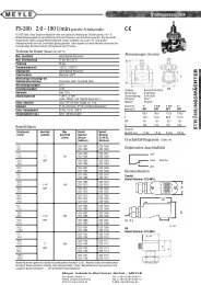
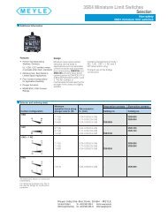
Pull-rope Emergency Switch SN<br />
VDE-aproved<br />
Pull-rope Emergency Switch Type SN<br />
Technical Data<br />
• Double-sided actuation <strong>for</strong> up to 50 m<br />
rope each<br />
• Up to 4 contacts NO and 4 contacts NC<br />
• Interlocking in actuated position with<br />
manual reset only<br />
• Snap action safety contacts with <strong>for</strong>ced-<br />
opening system<br />
• Meet any new European Security<br />
Standard<br />
• Certified according to VDE -0660/200<br />
• Reliable operation by high rope tension<br />
and large actuation travel<br />
• 2 cable inlets with PG 16 or ½“NPTF<br />
threads<br />
• Type of enclosure IP 65<br />
• Version with CSA (Canadian Standard<br />
Association) approval.<br />
Rope-operated emergency switches are<br />
used to give personal and process safety of<br />
<strong>conveyor</strong>s or other enlarged machines or lines<br />
Technical Data<br />
and to stop them from any point. Pulling on<br />
the rope actuates the switch and effects emer-<br />
gency stop demand.<br />
Rope-operated emergency switches type SN<br />
are <strong>for</strong> double-sided rope mountings. Pulling<br />
on one of the ropes actuates the switch via a<br />
snap action and interlocks. Simultaneously<br />
with the actuation of the switch interlocking is<br />
being effected. Switch position and pulling<br />
direction is indicated by the position of the<br />
locked switch lever. Even if there should be a<br />
spring break within the switch or the<br />
contacting areas should be baken together the<br />
installed <strong>for</strong>ced opening system effects a<br />
secure opening of the circuits. Release/reset<br />
of the switch`s interlocking can only be<br />
per<strong>for</strong>med manually and having direct access<br />
to the switch assembly – there is no remote<br />
reset possible.
The switch can be supplied with up to four<br />
single-circuit two-way contacts or with up to<br />
four contacts NO and four contacts NC.<br />
All switching contacts are commutated<br />
simultaneously, independent of the direction<br />
from which the switch has been actuated.<br />
These switches are designed to be installed in<br />
between two ropes. The maximum rope<br />
lengths supported by the switches should not<br />
exceed 50m <strong>for</strong> each rope. Malfunctions of<br />
rope operation and unwanted stops caused by<br />
vibrations or thermical tensions within the<br />
length of the ropes, or other unwanted<br />
physical influences, are extremely unlikely due<br />
to the large rope travel and the large tension<br />
(>40 N) necessary <strong>for</strong> switching.<br />
The standard <strong>for</strong> automatic emergency stop<br />
due to rope break, DIN EN 418 paragraph<br />
4.5.2, is fulfilled when used with two preload<br />
springs RZ168 available out of our accessory<br />
programme.<br />
The material of the switch housing is coloured<br />
glas fibred rein<strong>for</strong>ced polyester. Stability of the<br />
polyester enclosure is comparable to that of<br />
cast iron housing. Polyester, however, is not<br />
so brittle and thus more resitant against<br />
Pull Rope Arrangement, Version A<br />
shock. It is dust- and waterproof housing<br />
(IP65).<br />
The switches are guaranteed <strong>for</strong> an extended<br />
working life: The use of sealing rings<br />
protecting all ducts out of the housing, shafts<br />
made of stainless VA-Steel, screws made of<br />
stainless VA-steel, loss protected housing<br />
cover screws.......<br />
Variations<br />
Pull-rope Arrangement, Version B VDE 0113, DIN EN 418<br />
- 8-digit clamp with complete internal wiring<br />
<strong>for</strong> easyest installation of your electrical<br />
wiring<br />
- Pull-off dislocking lever<br />
- Installation of a signal lamp<br />
- Version with approval by the Canadian<br />
Standard Association<br />
- EEX and SCH protected and approved<br />
versions<br />
Accessoires:<br />
1 eye screw M6x60 5 rope clamp 3/16“<br />
2 turnbuckle M6x110 6 wire loop M8x80 with bolt<br />
3 spring RZ168 7 pull rope: steel rope with red PVC sheathing<br />
4 rope eye 3/16“ 8.spring bridge
Technical Data:<br />
Certification VDE 0660, part 200, reg.no 5136<br />
Con<strong>for</strong>ms to standards IEC 947-5-1/EN 60947-5-1/DIN EN 292/UVV-VBG10<br />
DIN EN 418 if equipped with two preload springs<br />
Rope travel 42 mm<br />
Rope tension <strong>for</strong> actuation 40 N<br />
Cable inlet 2 x PG 16 threaded hole<br />
Or per adapter (accessory) ½“ NPTF<br />
Type of enclosure IP 65<br />
Housing material Glass fibre rein<strong>for</strong>ced polyester housing<br />
Housing colour Yellow RAL 1004 or red RAL 3000<br />
Weight 2,3 kg<br />
Fixing 2 long holes <strong>for</strong> M10-screws<br />
Operating temperature -40°C up to +85°C<br />
Selection table<br />
Switch type Contacts Rating Remarks<br />
NO NC alternating switch<br />
SN 1-1 1 1 230 VAC, 1 A Rubbing contacts<br />
SN 1-2 2 2 230 VAC, 1 A selfcleaning<br />
SN 1-3 3 3 230 VAC, 1 A designed <strong>for</strong> low<br />
SN 1-4 4 4 230 VAC, 1 A current<br />
SN 2-1 1 230 VAC, 8 A Single circuit 2way cont<br />
SN 2-2 2 230 VAC, 8 A Single circuit 2way cont<br />
SN 2-3 3 230 VAC, 8 A Single circuit 2way cont<br />
SN 2-4 4 230 VAC, 8 A Single circuit 2way cont<br />
Dimensions:
06.424/0698 (Subject to alteration)<br />
Meyer <strong>Industrie</strong>-<strong>Electronic</strong> <strong>GmbH</strong><br />
Carl-Bosch-Straße 8<br />
49525 Lengerich<br />
Tel. (+ 49 54 81) 93 85 - 0<br />
Fax (+ 49 54 81) 93 85 - 12<br />
EMail: sales@meyle.de<br />
Address
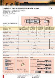
Pull-rope emergency switch with - protected contacts<br />
Type SN-EML<br />
According to the ATEX-guideline - <strong>for</strong> use in zone 21 and 1<br />
Application<br />
The design of these pull-rope<br />
emergency switches considerates<br />
heavy duty service. Housings made of<br />
grey cast iron are the best guarantees<br />
<strong>for</strong> long years of reliable service. The<br />
type is IP66 protected (water- and dust<br />
proof). The equipment of these switches<br />
with explosion-protected and approved<br />
contacts qualifies them <strong>for</strong> use in zone<br />
21 as well as in zone 1. Pull-rope<br />
emergency switches of this type are <strong>for</strong><br />
double-sided rope mounting with a rope<br />
length of max 2 x 50 metres. Pulling on<br />
one of these ropes actuates all contacts<br />
via a snap action mechanism<br />
independent on the direction of<br />
Technical Data<br />
Technical Data<br />
Pull-rope Emergency Switch Type SN-EML<br />
actuation. Simultaneously with the<br />
actuation of the switch the latching is<br />
being automatically effected. Pulling<br />
direction is indicated by the position of<br />
the latched switch lever. The direct<br />
opening system of the contacts <strong>for</strong>ces<br />
the NC-contacts into open position<br />
under all conditions. These switches<br />
will be equipped individual with up to 4<br />
contacts. All contacts switch over<br />
independent on the direction of the<br />
actuation. The contact surfaces are<br />
made of silver or are optional gold<br />
plated. For low tensions and smallest<br />
currents the gold contacts are recommended.<br />
1 or 2 cables, standard 5m<br />
long, fix welded to the contacts, are<br />
<strong>for</strong> electrical connection either in Ex -<br />
free or in Ex -protected atmospheres.<br />
The large pull-rope travel (33mm,<br />
longitudinally drawn) and the large<br />
rope tension necessary <strong>for</strong> switching<br />
prevent unwanted stops caused by<br />
solids falling onto the pull-rope cord.<br />
The housings of most tough polyester<br />
are resistant against corrosion, <strong>for</strong><br />
use in all aggressive atmospheres,<br />
the housings of cast iron are used<br />
when hot materials can fall onto the<br />
housing.
Pull Rope Arrangement, Version A<br />
Pull-rope Arrangement, Version B VDE 0113, DIN EN 418<br />
Accessoires:<br />
1 eye screw M6x60 5 rope clamp 3/16“<br />
2 turnbuckle M6x110 6 wire loop M8x80 with bolt<br />
3 spring RZ168 7 pull rope: steel rope with red PVC sheathing<br />
4 rope eye 3/16“ 8.spring bridge<br />
Technical Data<br />
Certification of contacts EEx d II C T6, II 2 G, II 2 D T80 °C<br />
<strong>for</strong> use in zone 21 and 1<br />
Con<strong>for</strong>ms to standards ATEX / EN 60 947-5-1 / EN 60954 / EN 292 /<br />
UVV-VBG10 / DIN EN 418 if equipped with 2 springs SPF<br />
Rope travel <strong>for</strong> actuation 33 mm<br />
Rope <strong>for</strong>ce <strong>for</strong> actuation ›40 N<br />
Connection cable 1 or 2 cables, each 5m<br />
Contacts Up to 2 NC with direct opening plus 2 NO<br />
Switching capacity silver contacts: ohmic 230 VAC 5 A / 30 VAC 7 A<br />
cos phi 0,6 250VAC 3A / 30 VAC 5 A<br />
gold plated: min 5V / max 30V<br />
min 4 mA / max 400 mA max 0,12 VA<br />
Housing material grey cast iron<br />
Housing colour yellow or red<br />
Protection IP 66<br />
Weight 5.6 kg<br />
Fixing 2 holes <strong>for</strong> M10-screws<br />
Operating temperature -40°C up to +85 °C
Selection table<br />
Type Contacts<br />
NO NC<br />
SN1-EML 1 1 silver contacts<br />
SN2-EML 2 silver contacts<br />
SN21-EML 2 1 silver contacts<br />
SN22-EML 2 2 silver contacts<br />
Dimensions:<br />
Address
06.424/0698 (Subject to alteration)<br />
Meyer <strong>Industrie</strong>-<strong>Electronic</strong> <strong>GmbH</strong><br />
Carl-Bosch-Straße 8<br />
49525 Lengerich<br />
Tel. (+ 49 54 81) 93 85 - 0<br />
Fax (+ 49 54 81) 93 85 - 12<br />
EMail: sales@meyle.de<br />
Address
Signal Combination Type SK<br />
with pull-rope emergency switch,<br />
horn and warning light<br />
Technical Data
06.424/0698 (Subject to alteration)<br />
Meyer <strong>Industrie</strong>-<strong>Electronic</strong> <strong>GmbH</strong><br />
Carl-Bosch-Straße 8<br />
49525 Lengerich<br />
Tel. (+ 49 54 81) 93 85 - 0<br />
Fax (+ 49 54 81) 93 85 - 12<br />
EMail: sales@meyle.de<br />
Address
Alarm signal post Type SM<br />
With pull-rope emergency switch, horn and flashing light<br />
Application<br />
The trade co-operative associations<br />
of today demand sharper measures<br />
<strong>for</strong> prevention of accidents, which<br />
are also used as guidelines by the<br />
technical supervisory bodies.<br />
One such safety measures is the installation<br />
of pull-rope emergency<br />
switches. They have proved themselves<br />
an effective means of acci-<br />
dent prevention on innumerable<br />
<strong>conveyor</strong> belt systems, in iron and<br />
steel works, in the quarrying and<br />
earth moving industries, in trans -<br />
shipment facilities, the chemical<br />
industry and open pit mining.<br />
For extended <strong>conveyor</strong> systems<br />
Techcal Data<br />
Technical Data<br />
In particular, such pull-rope<br />
emergency switches can be<br />
supplied as alarm signal post type<br />
SM. This alarm signal post is<br />
installed on the approach side of<br />
<strong>conveyor</strong> belt systems or<br />
machines and - apposed to the<br />
Emergency-OFF push buttons<br />
located at certain intervals - it can<br />
be operated at any point along the<br />
length of a section and, depending<br />
on the system, can disconnect<br />
single or multiple drives or even<br />
the total plant as a whole. The<br />
actuated switch is identifiable by<br />
way of the visual and audible<br />
signals.<br />
Design<br />
The alarm signal post type SM<br />
consist of<br />
• pull-rope emergency switch<br />
• flashing light<br />
• horn<br />
• terminal box<br />
Use of part of the equipment (i.e.<br />
only horn or only flashing light) is<br />
possible. Flashing lights and horns<br />
are also available <strong>for</strong> different<br />
voltages.<br />
The terminal box is of ample size<br />
to enable other local devices to be<br />
connected to the terminals. The<br />
connection leads enter the<br />
terminal box from below.
The central functional element of<br />
the alarm signal post type SM is the<br />
pull-rope emergency switch NSR or<br />
SN; the switch mechanism is<br />
constructed in a manner which<br />
ensures that it remains functionable<br />
even if the retraction spring is<br />
broken. In order to prevent loss of<br />
functional safety as a result of<br />
soiling, the retraction spring is<br />
located inside the housing.<br />
The pull-rope emergency switch is<br />
- accordance with trade association<br />
recommendations - fitted with a<br />
locking mechanism which becomes<br />
effective when the switch is<br />
operated. Unlocking can be<br />
undertaken locally by means of a<br />
release lever, which is firmly<br />
attached. The device comes with<br />
Fig. 2 Dimension Drawing<br />
two switching elements; provision<br />
is made <strong>for</strong> extension by a further<br />
switch element. Selflubricating<br />
sinter bearings ensure almost<br />
complete freedom from maintenance<br />
work. The pull-rope<br />
- attached at both sides of the<br />
switch lever - protects a length of<br />
up to 100m. The use of a rope<br />
break safety device ensures that<br />
the switch is automatically<br />
actuated in the event of a one<br />
sided cutting of the pull-rope.<br />
Mode of operation<br />
The switch lever of the pull-rope<br />
emergency switch is reflected by<br />
pulling the rope and the switching<br />
element is actuated. The NOcontact<br />
of the element opens the<br />
safety chain of the controls and<br />
Fig.3 Terminal Diagram<br />
thereby effects switching-off the<br />
<strong>conveyor</strong> belt drive and, at the<br />
same time, the flashing light and<br />
the horn are activated. The<br />
location of the switch-off can thus<br />
be identified by signals, which can<br />
be seen and/or from a distance.<br />
The locking device, which comes<br />
into play upon deflection of the<br />
switch lever, holds the switch<br />
mechanism in the OFF-position.<br />
The locking device can be<br />
released by the firmly attached<br />
component lever, depending on<br />
the respective works regulations.<br />
The built-in switch elements have<br />
snap-contacts and a compulsory<br />
opening system and thus meet<br />
international safety regulations..
Pull Rope Arrangement, Version A<br />
Pull-rope Arrangement, Version B VDE 0113, DIN EN 418<br />
Accessoires:<br />
1 eye screw M6x60 5 rope clamp 3/16“<br />
2 turnbuckle M6x110 6 wire loop M8x80 with bolt<br />
3 spring RZ168 7 pull rope: steel rope with red PVC sheathing<br />
4 rope eye 3/16“ 8.spring bridge
06.424/0698 (Subject to alteration)<br />
Meyer <strong>Industrie</strong>-<strong>Electronic</strong> <strong>GmbH</strong><br />
Carl-Bosch-Straße 8<br />
49525 Lengerich<br />
Tel. (+ 49 54 81) 93 85 - 0<br />
Fax (+ 49 54 81) 93 85 - 12<br />
EMail: sales@meyle.de<br />
Address
Pull-rope Emergency Switch<br />
Type SNA 4<br />
• Unique, patented security<br />
system <strong>for</strong> competitiveless, up<br />
graded security standard<br />
• Max 2 x 75m pull cord<br />
• Direkt opening<br />
• Snap action<br />
• 2 NO contacts and 2 NC contacts<br />
• Cast-iron enclosure<br />
• IP 65<br />
• Utmost operating security by high rope<br />
tension and large actuation travel<br />
• and large actuation travel<br />
Pullcord switches are used to stop<br />
<strong>conveyor</strong>s or other enlarged machines from<br />
any point along. Manual pull on the rope,<br />
hanged in the switch, effects emergency stop<br />
demand.<br />
Target of the design of this switch is to offer a<br />
most reliable and safe service under all heavy<br />
duty conditions. Pullcord switches type SNA 4<br />
are designed <strong>for</strong> double-sided pull rope<br />
mounting. When pulled, the commutation<br />
happens in snap action characteristic. The<br />
incorporated direct opening system of the<br />
Technical Datas ..<br />
Pull-rope Emergency Switch Type SNA 4<br />
contacts <strong>for</strong>ces the NC-contacts into open<br />
position even if the contact surfaces are<br />
welded by short circuit. Simultaneously with<br />
the switching over, automatic latching of the<br />
switch mechanism and the decoupling of the<br />
switch mechanism of the actuating lever<br />
happens. Neither through the influences of<br />
violence - regarding the actuating lever - the<br />
latching of the switch mechanism may be<br />
released. Release of the effected latching is<br />
only possible manually and directly at the<br />
here<strong>for</strong>e provided lever. Further to the existing<br />
security systems, another patented system<br />
stands <strong>for</strong> a competent latching of the switch<br />
mechanism when actuating the lever even if<br />
the manual release lever has been blocked in<br />
its releasing position. The switch-position is<br />
indicated behind lenses on both sides of the<br />
switch.<br />
Rope-operated emergency stop switches<br />
type SNA 4 are equipped with 2 NO contacts<br />
and NC contacts. All installed contacts are<br />
actuating simultaneously, independent of the<br />
direction, from which the rope is being pulled.<br />
The switch is fully cabled besi one terminal<br />
strip in a separate connection box.
The switch is being provided <strong>for</strong> double-sided<br />
equipment and actuation with pull ropes,<br />
whereby the length of the pull ropes should<br />
not exceed 75 m per side. Malstops being<br />
provoqued by vibrations within the pull rope<br />
or unwanted physical influences to the pull<br />
rope etc. are extremely unlikely due to the<br />
large rope travel (35 mm, longitudinally drawn)<br />
and the large rope <strong>for</strong>ce (75 N) necessary <strong>for</strong><br />
the switching order.<br />
Dimensions:<br />
Technical Data:<br />
The switch enclosure is made of stable castiron.<br />
It is a water- and dust protected<br />
enclosure IP 65. Guarantee <strong>for</strong> a long<br />
working life and reliability are such unvisible<br />
details as sealing rings which are protecting<br />
all shafts guided out of the housing, shafts<br />
made of stainless VA-steel, screws made of<br />
stainless VA-steel, loss-protected housing<br />
cover screws etc. .<br />
Con<strong>for</strong>ms to standards DIN EN 60947 / EN 0418 / UVV-VBG10<br />
rope travel <strong>for</strong> actuation 35 mm<br />
rope <strong>for</strong>ce <strong>for</strong> actuation 75 N<br />
thread of cable gland 1 x M 25x1,5<br />
contacts 2 NO contacts and 2 NC contacts<br />
current rates 230VAC 5,5kW / 380VAC 9,5kW / 500V 12,5kW<br />
protection IP 65<br />
Fixing 2 long holes <strong>for</strong> M10-screws<br />
housing material cast-iron<br />
fixing 2 long holes <strong>for</strong> M10-screws<br />
installation position any<br />
housing colours yellow RAL 1003 or red RAL 3000<br />
Operating temperature -40°C up to +85°C<br />
storing temperature -50°C up to +85°C<br />
weight 15 kg<br />
06.424/0698 (Subject to alteration)<br />
Meyer <strong>Industrie</strong>-<strong>Electronic</strong> <strong>GmbH</strong><br />
Carl-Bosch-Straße 8<br />
49525 Lengerich<br />
Tel. (+ 49 54 81) 93 85 - 0<br />
Fax (+ 49 54 81) 93 85 - 12<br />
EMail: sales@meyle.de<br />
Address
Off-Track Off-Track Belt Belt Switches<br />
Switches<br />
Type Type BSR BSR and and Type Type BSO<br />
BSO<br />
VDE-approved<br />
VDE-approved<br />
Application<br />
Application<br />
Application<br />
The straight run of troughed <strong>conveyor</strong> <strong>belts</strong> is a<br />
decisive factor in safe, economic operation. In<br />
spite of several mechanical precautions, external<br />
influences caused by local conditions may effect<br />
the belt's straight running.<br />
The most frequent causes <strong>for</strong> slant running are<br />
- soiling of the support rollers and tail belt drums<br />
- off-center material loading<br />
If such or similar situations occur, the <strong>conveyor</strong><br />
belt concerned and the supply <strong>belts</strong> are to be<br />
switched off to prevent damage, destruction,<br />
spillage of material, erroneous discharge, and<br />
the resulting expensive consequences.<br />
ASG supplies practically proven off-track belt<br />
switches as safety devices <strong>for</strong> supervision of the<br />
belt run.<br />
Technical Data<br />
Configuration Configuration and and and features<br />
features<br />
Operating mechanism and switching elements of<br />
the switches type BSO and BSR are accommodated<br />
in a sturdy, glass-fiber rein<strong>for</strong>ced plastic<br />
housing, enclosure IP 65, which meets heavy duty<br />
requirements in any respect.<br />
It is equipped with two holes <strong>for</strong> leads PG16<br />
which are plugged <strong>for</strong> shipping (plugs not <strong>for</strong> use<br />
in operation). The switching mechanism makes<br />
the off-track belt switch staying operational even<br />
in case of broken springs.<br />
The off-track belt switch type BSO is provided<br />
witch a switch mechanism without without without latch, the<br />
type BSR with with with an effective latch when being<br />
operated.<br />
The release cam lever snaps into the latches only<br />
when the switching position is reached. It can be<br />
released only locally with a tight mounted<br />
release lever.
Switching Angle 15°, 25° or 42°<br />
Pre-connect<br />
switching Angle 10°or 20°<br />
Off-switching with latching<br />
max. 70°<br />
Release lever<br />
when latched<br />
37,5<br />
9<br />
160<br />
175<br />
25°<br />
Arrangement of the off-track belt switch on the <strong>conveyor</strong> system<br />
b<br />
95<br />
x<br />
ř 50<br />
The off-track belt switch type BSO 0.. is available<br />
with max. three switching elements, while at the<br />
type BSR 0.. the status of the latching is indicated<br />
by an additional switching element.<br />
At the types BSO.. +V and BSR.. +V max. two<br />
switches are dedicated to connecting at a rolling<br />
lever deflection of 15°, 25°, and 42° and one<br />
switch is dedicated to a pre-connecting at a lever<br />
deflection of 10° or 20°. The switching angles are<br />
selected by removal of the corresponding cams<br />
on the cam discs at all types of BSO and BSR.<br />
The max. rolling lever movability (deflection)<br />
amounts to 70° to both sides.<br />
The items in fact do not require any maintenance<br />
by the patented switching mechanism. If required,<br />
the items are available with a signal lamp<br />
integrated into the cover.<br />
Mounting example BSR / BSO<br />
Belt<br />
tail belt drum<br />
drive drum<br />
h<br />
Rolling lever<br />
continously-variable adjustment<br />
Switching Angle 15°, 25°, 42°<br />
Pre-connect switching Angle 10°, 20°<br />
Off-switching with latching 25°<br />
X is the distance between belt and<br />
drum edge<br />
at x < 60mm, b=107mm, h=132mm<br />
at x > 60mm, b=92mm, h=152mm<br />
Mode Mode of of Operation<br />
Operation<br />
Operation<br />
Off-track belt switches of types BSO 0.. and BSR<br />
0.. are mounted on both sides of the <strong>conveyor</strong><br />
belt close to the drive drum and the tail belt<br />
drum. Very long <strong>conveyor</strong> <strong>belts</strong> require further<br />
off-track belt switches.<br />
The type BSR prohibits an unintended, automatic<br />
re-starting because it must locally be released.<br />
Both types ensure a high switching safety. The<br />
switching elements used have pre-loaded spring<br />
contacts and cogent-opening system and, by this,<br />
meet international standards.<br />
The switching elements are appropriate to solve<br />
switching problems and to control optical or<br />
acoustical reporting devices as well.
Technical Technical Technical Data<br />
Data<br />
Type BSO BSO 01 BSO 02 BSO 03<br />
Connection<br />
BSO 01 +V BSO 02 +V<br />
Switching elements 1 x S 840 2 x S 840 3 x S 840<br />
Type BSR BSR 01 BSR 02 BSR 03<br />
Connection<br />
BSR 01 +V BSR 02 +V<br />
Switching elements 2 x S 840 3 x S 840 4 x S 840<br />
Duration current 230V/6A (at Ohm charge)<br />
Isolation 2,5 KV/3 (VDE 0110)<br />
Switching contact durability 3 x 10 5 switchings; switching frequency 150/h<br />
Switching contact gap 0,75 to max. 1,5mm˛<br />
Short cut protection required (fuse) 6 A<br />
VDE-Classification AC 11<br />
Specifications met EN 60 947-5-1 (DIN VDE 0660 T200)<br />
EN 60 947-5-1 / A1 (DIN VDE 0660 T200 / A1)<br />
Application Devices and controls to VDE 0100 and 0113<br />
Housing GFK (Glass fibre rein<strong>for</strong>ced plastic),<br />
resistant against water solutions of<br />
salts, acids, and alkalines, alcohol and solvent<br />
Colour Housing: yellow, RAL 1004<br />
Reset lever: red, RAL 3000<br />
Weight 1,8 kg approx<br />
Enclosure (according to DIN 40050) IP 65<br />
Installation orientation Preferably upright, i.e. activation lever up<br />
Mechanical duration 1 x 10 5 Switchings (according to DIN 46 247 part 2, version 4,<br />
point 3, section 4.21 and DIN 41 636 part 1, point 6.9)<br />
Cable routing threaded holes, 2 x PG16<br />
Ground connection in housing<br />
Permissibe envoirement temperature Storage -40°C...+85°C<br />
Operation -40°C...+85°C<br />
Transport -40°C...+85°C<br />
Max. equipment 3 alternating switches (BSO)<br />
4 alternating switches (BSR)<br />
Signal lamp (Option) 12, 24, 60, 220V<br />
max. 5 W<br />
Exchange with predecessor By adapter plate the BSR 0... / BSO 0... can be mounted on the<br />
attachment flange with the holes arrangement<br />
of the predecessor BSR... / BSO...
Safety Safety Instructions<br />
Instructions<br />
• The plugs are only <strong>for</strong> dirt protection, they are<br />
not <strong>for</strong> use in operation<br />
• PG-screwings must be sealed with an sealing<br />
against the housing<br />
• PG-screwings witch are not in use must be<br />
closed by a plug and sealing<br />
• The inner cabeling must be routed in a way<br />
that a single wire cannot fall into the<br />
mechanical arrangement in case of a<br />
becoming loose. This is preferabely achieved<br />
by cable binders holding together all single<br />
wire<br />
The following must be inspected periodically<br />
during operation of an off-track belt switch:<br />
• Safe attachment of the off-track belt switch<br />
• Cleanliness of item and freedom from belt<br />
loading material and similar particles<br />
• Absence of signs of damages like cracks,<br />
corrosion, de<strong>for</strong>mation<br />
Dimension BSO / BSR<br />
06.417/0498 (Subject to alteration)<br />
• Absence of <strong>for</strong>eign particles in influences<br />
collected at the device which could obstruct<br />
activation parts<br />
• Absence of obstacles near the roller lever<br />
Periodical Periodical Check Check <strong>for</strong> <strong>for</strong> proper proper Function<br />
Function<br />
The proper function of the off-track belt switch<br />
is checked during stopping the <strong>conveyor</strong> belt by<br />
the device or by observing the device during<br />
standstill of the <strong>conveyor</strong> belt:<br />
• Easy movement of rolling lever and<br />
movement from transmitting parts<br />
• Reliable selflatching of rolling lever in Off-<br />
Position<br />
• Release of rolling lever not too easy<br />
In case of anomalies detected during inspection,<br />
these are immediately to be solved or the item<br />
concerned is to be replaced <strong>for</strong> further<br />
investigation.<br />
Meyer <strong>Industrie</strong>-<strong>Electronic</strong> <strong>GmbH</strong><br />
Carl-Bosch-Straße 8<br />
49525 Lengerich<br />
Phone (+ 49 54 81) 93 85 - 0<br />
Fax (+ 49 54 81) 93 85 - 12<br />
EMail: sales@meyle.de<br />
Address
Off-Track Belt Switches<br />
Typ FSR und FSO<br />
VDE-tested<br />
Application<br />
The straight run of troughed <strong>conveyor</strong><br />
<strong>belts</strong> is a decisive factor in safe, economic<br />
operation. In spite of several mechanical<br />
precautions, external influences<br />
caused by local conditions, may effect<br />
the <strong>belts</strong> straight running.<br />
The most frequent causes are<br />
- soiling of the support rollers and tail<br />
belt drums<br />
- off-center material loading.<br />
If such or similar situations occur, the<br />
<strong>conveyor</strong> belt concernd and the supply<br />
<strong>belts</strong> are to be switched off to prevent<br />
- damage<br />
- destruction<br />
- spillage of material<br />
- erroneous discharge<br />
and the result possibly expensive consequences<br />
Design<br />
Technical Data<br />
Off-Track Belt Swithes Typ FSR with latching<br />
Operation mechanism and switching<br />
elements of the switches FSO and<br />
FSR are accomodated in a sturdy,<br />
glass-fiber rein<strong>for</strong>ced plastic housing,<br />
enclosure IP 65, Which meets in every<br />
aspect heavy duty requirements.<br />
Two threaded bushes <strong>for</strong> cable glands<br />
PG16 are provided <strong>for</strong> lead-in. The<br />
switching mechanism is designed in<br />
such a way that the track-off belt switch<br />
remains operational even with a<br />
damaged retraction spring. In order to<br />
prevent loss of functional safety as a<br />
result of soiling, the retraction spring<br />
has been placed inside the housing<br />
The off-track belt switch FSO is provided<br />
with a switch mechanism without<br />
latch, the type FSR with an effective<br />
latch when being operated.<br />
The release cam lever only latches<br />
when the switching position is reached.<br />
With constant movement of the roller<br />
Lever by the belt, mechanical wear<br />
and tear is thus avoided. Unlatching<br />
can take place locally by an incorporated<br />
or separately supplied release<br />
lever.<br />
The off-track belt switches of the types<br />
FSO and FSR are available with two<br />
or three switching elements respectively.<br />
In the case of the the switches<br />
FSO 2/1+V, two switching elements<br />
<strong>for</strong> the limit switching-off with a lever<br />
deflection of 12°-15° are provided <strong>for</strong>.<br />
The robust, long roller lever is equipped<br />
with ball bearings and suitable <strong>for</strong><br />
deflection of 75° on both sides. The<br />
devices nearly do not need any maintenance.
Arrangement of the off-track belt swithes on the <strong>conveyor</strong> system<br />
Functioning<br />
Off-track belt switches FSO and FSR are<br />
monted on both sides of the belt near to the<br />
tail belt and drive drums. In the case of extremely<br />
long <strong>belts</strong>, further switches shold be<br />
provided <strong>for</strong> according to further sources of<br />
danger expected.<br />
Utilization of the type FSR does not allow <strong>for</strong><br />
Unintentional, automatic switchingon,<br />
since local release is required.<br />
Both types ensure a high degree of<br />
switching reliability. The built-in<br />
switching elements are equipped with<br />
snap contacts and compulsory break<br />
system and thus comply with international<br />
regulations. With tree swit<br />
Co-ordination of the off-track belt switch with the other safety devices<br />
ching tasks can be solved and addi-<br />
tional audio or visual control faciities<br />
can be triggered.
06.424/0698 (Subject to alteration)<br />
Meyer <strong>Industrie</strong>-<strong>Electronic</strong> <strong>GmbH</strong><br />
Carl-Bosch-Straße 8<br />
49525 Lengerich<br />
Tel. (+ 49 54 81) 93 85 - 0<br />
Fax (+ 49 54 81) 93 85 - 12<br />
EMail: sales@meyle.de<br />
Address
Off-Track Belt Switches with - protected contacts<br />
Type FSR-EML und FSO-EML<br />
According to the ATEX-guideline - <strong>for</strong> use in zone 21 and 1<br />
Application<br />
The straight run of troughed <strong>conveyor</strong><br />
<strong>belts</strong> is a decisive factor in safe, economic<br />
operation. In spite of several mechanical<br />
precautions, external influences<br />
caused by local conditions, may effect<br />
the <strong>belts</strong> straight running.<br />
The most frequent causes are<br />
- soiling of the support rollers and tail<br />
belt drums<br />
- off-center material loading.<br />
If such or similar situations occur, the<br />
<strong>conveyor</strong> belt concernd and the supply<br />
<strong>belts</strong> are to be switched off to prevent<br />
- damage<br />
- destruction<br />
- spillage of material<br />
- erroneous discharge<br />
and the result possibly expensive consequences<br />
.<br />
Design<br />
Technical Data<br />
Off-Track Belt Swithes Typ FSR-EML with latching<br />
The equipment of these switches with<br />
EX-protected and approved contacts<br />
qualifies them <strong>for</strong> use in explosive<br />
areas zone 21 as well as zone 1<br />
according to the ATEX-guideline. The<br />
design of these misalignment switches<br />
considerates heavy duty service.<br />
Housings made of grey cast iron or of<br />
most stable, impact resistant, thickwalled<br />
and strongly oxydating<br />
atmospheres resistant fibre glass<br />
rein<strong>for</strong>ced polyester as well as the<br />
roller levers made of stainless steel, are<br />
the best guarantees <strong>for</strong> long years of<br />
reliable service. Both housings are<br />
IP66 protected (water- and dust proof).<br />
These misalignment switches should<br />
be installed pairwise, left and right of<br />
the <strong>conveyor</strong>. In case that the<br />
conveying belt misalign from the given<br />
track, one roller lever of these switch<br />
pair will be touched by the edge of the<br />
belt and displaced against the resetting<br />
<strong>for</strong>ce of an switch-internal spin. Actua-<br />
tion of the contacts is being effected in<br />
snap-action characteristic if the lever<br />
is displaced 7cm out of the neutral<br />
position. The maximum displacement<br />
angle of the roller lever is 75°.<br />
Optional is a 2- stage switch, first<br />
stage <strong>for</strong> signalling and the second<br />
stage <strong>for</strong> cut off. Signalling happens at<br />
a displacement of 4cm, cut off at 7cm.<br />
In case that the value of misalignment<br />
is reduced reset happens<br />
automatically. A further version<br />
provides latching in main contacts<br />
actuated position. Stepless adjustable<br />
space between the roller lever and the<br />
edge of the belt by stepless adjusting<br />
of the lever on the switch shaft<br />
facilitates installation. The contact<br />
surfaces are made of silver or are gold<br />
plated optional. For low tensions and<br />
smallest currents the gold contacts are<br />
recommended. 1 or 2 cables, standard<br />
5m long each, fix welded to the<br />
contacts, are <strong>for</strong> electrical connection<br />
either in EX-free or EX-protected<br />
atmospheres.
Arrangement of the off-track belt swithes on the <strong>conveyor</strong> system<br />
Functioning<br />
Off-track belt switches FSO-EML and FSR-<br />
EML are mounted on both sides of the belt<br />
near to the tail belt and drive drums. In the<br />
case of extremely long <strong>belts</strong>, further<br />
switches shold be provided <strong>for</strong> according to<br />
further sources of danger expected.<br />
Utilization of the type FSR-EML does<br />
Utilization of the type FSR-EML does<br />
not allow <strong>for</strong> unintentional, automatic<br />
switching-on, since local release is<br />
required.<br />
Both types ensure a high degree of<br />
switching reliability. The built-in<br />
switching elements are equipped with<br />
Co-ordination of the off-track belt switch with the other safety devices<br />
snap contacts and compulsory break<br />
system and thus comply with international<br />
regulations. With tree swit -<br />
ching tasks can be solved and addi-<br />
tional audio or visual control faciities<br />
can be triggered.
Technical Data<br />
Con<strong>for</strong>mity ATEX / EN 60 947 / VDE 0168 / EN 60204<br />
Certification of contacts EEx d II C T6, II 2 G, II 2 D T80 °C<br />
approved <strong>for</strong> zone 21as well as 1<br />
Off-track <strong>for</strong> main contacts 7cm<br />
Off-track <strong>for</strong> warning contacts 4cm<br />
Max. displacement 75°<br />
Roller lever stainless steel, stepless adjustable , double stainless<br />
steel ball beared , 50mm diameter <strong>for</strong> low rotation<br />
speed and high lifetime<br />
Switching capacity silver contacts: ohmic 230 VAC 5 A / 30 VAC 7 A<br />
cos phi 0,6 250VAC 3A / 30 VAC 5 A<br />
gold plated: min 5V / max 30V<br />
min 4 mA / max 400 mA max 0,12 VA<br />
Utilisation category AC-15 2A 400V, DC-13 0,15A 250V<br />
Connection cable 1 or 2 cables, each 5m<br />
Housing material a) Fibre glass rein<strong>for</strong>ced polyester<br />
b) grey cast iron<br />
Weight a) 2.0 kg<br />
b) 5,6 kg<br />
Housing colour yellow or red<br />
Protection IP 66<br />
Fixing 2 holes <strong>for</strong> M10-screws<br />
Operating temperature -40°C up to +85 °C
06.424/0698 (Subject to alteration)<br />
Meyer <strong>Industrie</strong>-<strong>Electronic</strong> <strong>GmbH</strong><br />
Carl-Bosch-Straße 8<br />
49525 Lengerich<br />
Tel. (+ 49 54 81) 93 85 - 0<br />
Fax (+ 49 54 81) 93 85 - 12<br />
EMail: sales@meyle.de<br />
Address
Lever Limit Switch HE-...- Z<br />
· Up to 4 contacts NC and 4 contacts NO<br />
· Snap action safety contacts with<br />
· <strong>for</strong>ced-opening system<br />
· 2 cable ducts Pg16<br />
· Available with impact resistant<br />
· glass fibre rein<strong>for</strong>ced polyester,<br />
· optional cast iron enclosure<br />
· Type of enclosure IP 65<br />
· EEX protected version available<br />
· Version with CSA (Canadian<br />
· Standard Association) approval<br />
· Automatic latching in actuated<br />
· position with manual reset<br />
Lever Limit Switches are designed <strong>for</strong> signalling<br />
or cutting off at reached positions of linear or<br />
sviveling movements.<br />
MEYLE Lever Limit Switches of these types are<br />
equipped with an actuation lever which is pressed<br />
through an internal spring in its neutral position.<br />
When the roller of this actuation lever is moved<br />
against a cam or an actuation bar, the actuation<br />
lever is displaced from its neutral position to one<br />
of the both possible sides (left or right) against the<br />
<strong>for</strong>ce of the internal spring. At an displacement<br />
angle of 30° the commutation will happen in snapaction<br />
characteristic with a <strong>for</strong>ced opening of the<br />
NC-contacts. When leaving the area of cam or<br />
actuation bar, the lever is turned back to its<br />
Technical Data<br />
neutral position through the <strong>for</strong>ce of the internal<br />
spring and resetting happens with snap action<br />
(except <strong>for</strong> version „R“. At this point the actuation<br />
lever will be latched in actuated position<br />
automatically. Release of this latching only<br />
manually direct at the switch).<br />
These switches can be equipped with up to 4<br />
switching elements. Each switching element<br />
consists of one contact NC and one contact NO.<br />
They are actuated either simultaneously<br />
independent on the direction of displacement of<br />
the lever or they are actuated depending on the<br />
direction (see „selection table). Commutation is<br />
being effected at a displacement angle of 30°. The<br />
maximum displacement angle of roller lever is<br />
75°.<br />
The lever can be mounted in 4 positions on the<br />
shaft. The roller of the actuation lever is made of<br />
polyamide and is sleeve -beared on a stainless<br />
steel axle.<br />
The housing of this switch is made either of<br />
coloured, glass fibre rein<strong>for</strong>ced polyester or of<br />
cast iron (code „M“). Stability of the polyester<br />
enclosure is comparable to that of cast iron<br />
enclosures. Polyester, however, is not so brittle<br />
and thus more resistant against shocks. Both are<br />
dust- and waterproof housings (con<strong>for</strong>ming to<br />
IP65).<br />
The switches are guaranteed <strong>for</strong> an extended<br />
working life: The use of sealing rings protecting all<br />
ducts out of the housing, shafts made of stainless<br />
VA-steel, screws made of stainless VA-steel, lossprotected<br />
lid screws.
Variations<br />
• Pull-off release lever<br />
• CSA-aproval (separate data sheet)<br />
• EEX and SCH protected version (separate data sheet)<br />
• For easier installation of the electrical wiring a 8-digit clamp with internal wiring can be provided<br />
• Pre-contacts <strong>for</strong> prewarning at displacement angle of roller lever of 15°<br />
Technical Data<br />
Con<strong>for</strong>ms to standards EN 60 947-5-1 / EN 60954 / DIN EN 292<br />
Switch angle 30°<br />
Max. lever displacement 75°<br />
Height of actuation bar min. 20mm, max. 65mm<br />
Life electrical 5x10⁵ operations, mechanical 5x10⁵ operations<br />
Switching capacity 400VAC 6A / 230VAC 8A / 24VDC 10A / 80VDC 3A<br />
Cable ducts 2 x Pg 16 threaded hole<br />
Type of protection IP65<br />
Housing material Glass fibre rein<strong>for</strong>ced polyester (HE....), cast iron (HEM....)<br />
Housing color yellow RAL 1003 or red RAL 3000<br />
Weight 2.3 kg (HE-10x-Z), 5.9 kg (HEM-10x-Z)<br />
Fixing 2 long holes <strong>for</strong> M10-screws<br />
Operating temperature -40°C up to +85°C<br />
Selection table (there are more variations possible!)<br />
Glass fibre rein<strong>for</strong>ced polyester housing<br />
Typ number of switching elements actuated... latching<br />
depending on direction left only right only<br />
HEE 161-Z 1 no<br />
HEER 161-Z 1 yes<br />
HE 162-Z 2 no<br />
HER 162-Z 2 yes<br />
HE 163-Z 3 no<br />
HER 163-Z 3 yes<br />
HE 164-Z 4 no<br />
HER 164-Z 4 yes<br />
HE 162-Z2 1 1 no<br />
HE 164-Z2 2 2 no<br />
Cast iron housing as mentioned above, but use code „M“, e.g. HEM 161-Z.
Interlock Interlock Interlock Bypass Bypass Bypass Bypass Bypass Bypass Switch Switch Switch Switch Switch Type Type Type ESP<br />
ESP<br />
ESP<br />
<strong>for</strong> <strong>for</strong> <strong>for</strong> Operational Operational Operational Monitoring Monitoring Monitoring of of of Drives<br />
Drives<br />
Drives<br />
Application<br />
Application<br />
Application<br />
Interlock bypass switches of type ESP made by ASG are used<br />
to monitor semiautomatic or fully-automatic, proper<br />
mechanical operation of <strong>conveyor</strong> <strong>belts</strong> <strong>for</strong> cargo and bulk<br />
material systems arranged in series as well as of drives.<br />
They ensure operation by their application in circuitries <strong>for</strong><br />
interlocking of all drives, successive connection of drives<br />
opposite to the conveying direction and disconnection of all<br />
feeding drives of a driving chain upon failure of one drive.<br />
For maintenance and repair work, the interlock bypass<br />
units moreover enable the removal of one drive from a<br />
driving chain.<br />
By means of a corresponding circuit connections excessive<br />
piling and resulting damages of <strong>conveyor</strong> <strong>belts</strong> are avoided.<br />
In addition to the application in <strong>conveyor</strong> systems, interlock<br />
bypass switches may be used <strong>for</strong> all drives, the operation of<br />
which requires a mutual interlocking.<br />
Design Design Design and and and Construction<br />
Construction<br />
Construction<br />
Construction<br />
Construction<br />
Construction<br />
The sturdy compact casing of aluminum dry-casting with<br />
yellow plastic coating (RAL 1004) meets IP 65 enclosure and is<br />
capable of withstanding all conditions of rough operation.<br />
To avoid contact contamination or corrosion with opened<br />
cover, a deck switch is used. The switch knob is recessed in a<br />
triply lockable protective collar. The shaft with claw coupling<br />
connected to the knob is supported in a ball bearing with<br />
sealing in the cover and is arranged asymmetrically. Hence,<br />
the cover has to be attached inevitably.<br />
Technical Data<br />
To ensure correct engagement, the cover must be closed or<br />
opened resp. in the 0 position of the switch only. For single<br />
and reversing drives, merely one switch with different switch<br />
functions is installed. Two threaded bores, one PG 16 and<br />
one PG 21 - closed by pegs are provided <strong>for</strong> the cable leadin.<br />
There is one earthing screw inside and one outside the<br />
casing.<br />
Function<br />
Function<br />
Function<br />
Following a detailled survey on the various modes of the<br />
interlock bypass switches of types ESP 1 and 2.<br />
V V V interlocked interlocked interlocked interlocked interlocked interlocked operation operation operation operation<br />
operation operation (locked position)<br />
In position "V", the resp. drive can be switched on and off<br />
centrally only. There is a <strong>for</strong>ced interlocking of all drives.<br />
0 0 0 zero zero zero position<br />
position position (locked position)<br />
In position "0", the drive is taken out of the <strong>for</strong>ced inter<br />
locking and neither can be switched-on automatically nor<br />
manually.<br />
E E E released released released operation<br />
operation operation (locked position)<br />
Position "E" enables switching to I On <strong>for</strong> maintenance and<br />
repair operation.<br />
I I I On<br />
On On On On (non-locking position)<br />
If an individual drive shall be switched-on temporally e.g.<br />
<strong>for</strong> maintenance or repair, the switch knob standing in<br />
position "E" is to be pushed towards I "On". This switch<br />
position is non-locking. A locking design is possible, too.<br />
In case of the interlock bypass switch of type ESP 2 <strong>for</strong><br />
reversing drives, the modes listed above are available twice as<br />
you can see from the switch functions.
Technical Technical Data<br />
Data<br />
Designation Designation<br />
Interlock bypass switch with deck switch<br />
Type ESP 1 ESP 2<br />
Deck switch with self-cleaning contacts P10BC01.548 P10BC01.549<br />
switching capacity 10 A at 230 V<br />
switching angle 45°<br />
Dimensions (L x W x H) 120 x 122 x 91/140 mm<br />
Cable entries 1 x Pg16 and 1 x Pg21<br />
Weight 1.7 kg 1.8 kg<br />
Surface protection plastic coating, yellow (RAL 1006)<br />
Permissible environment temperature -25°C to +55°C<br />
Switch Switch Functions Functions Functions of of Interlock Interlock Bypass Bypass Switches Switches of of of Types Types ESP ESP ESP 1 1 and and ESP ESP ESP 2<br />
2<br />
Single drive ESP 1<br />
Reversing drive ESP 2<br />
left right<br />
06.501/052002 (Subject to alteration)<br />
Meyer <strong>Industrie</strong>-<strong>Electronic</strong> <strong>GmbH</strong><br />
Carl-Bosch-Straße 2<br />
49525 Lengerich<br />
Phone (+49 54 81) 93 85 - 0<br />
Fax (+49 54 81) 93 85 - 12<br />
E-Mail: sales@meyle.de<br />
Address
Unlocking Unlocking Devices Devices Type Type EGN<br />
EGN<br />
<strong>for</strong> <strong>for</strong> <strong>for</strong> the the Supervisory Supervisory Control Control of of Drives<br />
Drives<br />
1 2 3 4<br />
Application<br />
Application<br />
Unlocking devices type EGN from AEG are used<br />
<strong>for</strong> controlling the semiautomatic or fully<br />
automatic operation of in series connected<br />
<strong>conveyor</strong> <strong>belts</strong> <strong>for</strong> cargo and bulk material<br />
transport.<br />
The devices serve <strong>for</strong> guaranteeing the<br />
operation <strong>for</strong><br />
• the reciprocal interlocking of all drives<br />
• the starting of the drives one after the other<br />
against the conveying direction<br />
• the switching-off of all drives of a driving<br />
chain if one drive fails.<br />
When maintenance and repair work is carried<br />
out, the unlocking devices furthermore allow<br />
<strong>for</strong> - disconnecting a drive from a drive chain.<br />
This helps to avoid with corresponding connection<br />
spillage and thus damage to the <strong>conveyor</strong><br />
<strong>belts</strong>.<br />
Technical Data<br />
Design<br />
Design<br />
The housings of sturdy design coated with<br />
synthetic resin comply will all requirements of<br />
rough service and satisfy the enclosure IP 65.<br />
For single operation, a switch with the settings<br />
interlocked - O - unlocked as well as an off/ on<br />
switch are installed in the intermediate cover.<br />
To prevent unauthorized operation of the<br />
switches, the hinged cover with safety glassing<br />
can be closed by three padlocks. Furthermore,<br />
the interlocking and unlocking switch additionally<br />
can be equipped with a removable<br />
toggle (DBGM registered).<br />
For the reversing drive, additionally a selector<br />
switch <strong>for</strong> the sense of rotation with the<br />
settings left - O - right is installed.<br />
The types EGN2,EGN3 are equipped with 13 screw<br />
terminals, the types EGN2/3K with 20, from which<br />
max. 8 or 15 resp. are used. There<strong>for</strong>e, additional<br />
terminal boxes <strong>for</strong> connecting further local units<br />
will not be required in most cases.<br />
Picture: Picture: Picture: Picture: Picture: Unlocking Unlocking Unlocking Unlocking Unlocking devices devices devices devices devices of of of of of the the the the the types types types types types (/eft to right)<br />
1 EGN3 with three cam switches<br />
2 EGN3K+N with three cam switches and terminal box with emergency-off<br />
3 EGN3M with three cam switches and instrument box with measuring apparatus<br />
4 EGN3KM+N with three cam switches, terminal box with emergency-off and instrument box with measuring apparatus.
With type EGN and EGN.M,two threaded holes<br />
PG16 are provided <strong>for</strong> on the housing bottom<br />
as inlets <strong>for</strong> the leads, and with the type EGN.K<br />
and EGN.KM, the terminal box bottom is<br />
equipped with three threaded holes PG16 and<br />
one threaded hole PG21, each closed by a<br />
blind plug.<br />
Cam switches are provided <strong>for</strong> as switches <strong>for</strong><br />
the unlocking devices. The switch supports are<br />
EGN - Basic unit in open condition<br />
made of high quality, hardly inflammable and<br />
non tracking insulating material. Operational<br />
safety and reliable contacting properties, even<br />
at small voltages, are guaranteed by high<br />
contact pressure and double break silver nickel<br />
contacts. The unlocking devices are available in<br />
many different types. On page 4, the most<br />
important types are represented. Page 5 shows<br />
the available standard connections. On request,<br />
also special connections are carried out.<br />
Functioning<br />
Functioning<br />
The following tables describe the functioning of the unlocking devices <strong>for</strong> the different services.<br />
Functioning Functioning Functioning of of the the Unlocking Unlocking Unlocking Devices Devices with with Single Single Operation<br />
Operation<br />
Operation<br />
Operating as interlocking Functioning<br />
and unlocking switch<br />
V interlocked operation In the “V” position, the corresponding drive can only be centrally<br />
(switching position engaged) connected and disconnected, with a compulsoryinterlocking of all drives<br />
interlocking of all drives<br />
O zero position In the “0” position, the drive is disconnected from the compulsory interlocking<br />
(switching position engaged) and cannot be connected neither automatically nor manually<br />
E unlocking operation The “E” position allows <strong>for</strong> switching the On/Off switch <strong>for</strong> the<br />
(switching position engaged) maintenance and repair operation.<br />
Operating as On/Off switch Functioning<br />
On If a single drive shall be connected <strong>for</strong> a short time to carry out maintenance<br />
or repair work, the switch lever set to “center” has to be put to<br />
“On”. This switching position can be obtained by sensing or snapping.<br />
Central position With normal operation<br />
Button panel EGN2<br />
Button panel EGN3<br />
Off In this switching position, the drive is disconnected independent of<br />
interlocking and unlocking switch. This switching position can be obtained<br />
by sensing or snapping.
Functioning Functioning Functioning of of the the Righ/Left Righ/Left Switch Switch in in the the Case Case of of Reversing Reversing Drives<br />
Drives<br />
Operation Functioning<br />
Right (switching position engaged) Right-hand running of the drive<br />
0 (switching position engaged) Drive disconnected<br />
LeH (switching position engaged) Left-hand running of the drive<br />
Dimension sketch of unlocking device type EGN, with cam switches<br />
Dimensiones sketch of combined unlocking device type EGN.K+N with cam switch
Technical Data of Standard Unlocking Devices Type EGN2/3 and EGN2/3K+N with Cam SwitchType<br />
Type EGN2 EGN2K+N EGN3 EGN3K+N<br />
Standard connections see below (special connections on request)<br />
Cam number 1, 2, or 3 (4 on request)<br />
switches<br />
switching angle 45°<br />
rupturing capacity 10 A with 220 V, 50 Hz; 8 A with 380 V, 50 Hz<br />
Lamps 1 to 3<br />
Measuring see special types<br />
Line connections EGN. = 13 terminals; 2.5 mm˛<br />
EGN.K = 20 terminals; 2.5 mm˛<br />
Weights / Dimensions EGN2 = 4.4 kg 165 x 265 x 150<br />
EGN2K+N = 7.5 kg 165 x 540 x 100/150<br />
EGN3 = 4.5 kg 165 x 265 x 150<br />
EGN3K+N = 7.6kg 165 x 540 x 100/150<br />
Adm. temperature range - 25 °C to + 70 °C<br />
Housing material Al Si 12<br />
Surface protection pulverizated, yellow RAL 1006<br />
Enclosure IP 65 (by using key-switches IP54)<br />
Examples hr Special Types of Unlocking Devices on Request<br />
Type EGN4 EGN4K+N EGN2L2 EGN2KL2+N EGN3M EGN3KM+N
Available switch layouts
06.424/0698 (Subject to alteration)<br />
Meyer <strong>Industrie</strong>-<strong>Electronic</strong> <strong>GmbH</strong><br />
Carl-Bosch-Straße 8<br />
49525 Lengerich<br />
Tel. (+ 49 54 81) 93 85 - 0<br />
Fax (+ 49 54 81) 93 85 - 12<br />
EMail: sales@meyle.de<br />
Address
06.424/0698 (Subject to alteration)<br />
Meyer <strong>Industrie</strong>-<strong>Electronic</strong> <strong>GmbH</strong><br />
Carl-Bosch-Straße 8<br />
49525 Lengerich<br />
Tel. (+ 49 54 81) 93 85 - 0<br />
Fax (+ 49 54 81) 93 85 - 12<br />
EMail: sales@meyle.de<br />
Address
Optical & acustic<br />
Signal Devices
Warning Beacons<br />
Type 826<br />
Modern design<br />
Removal of the dome only possible with tools<br />
Simple mounting<br />
High protection rating IP 65 - suitable <strong>for</strong> indoor and outdoor use<br />
TECHNICAL SPECIFICATIONS<br />
Dimensions (Diameter x<br />
Height):<br />
Housing: ASB/PC<br />
100 mm x 138.5 mm<br />
Dome : Polycarbonate transparent<br />
Fixing: Base mounting, bracket mounting, tube mounting<br />
(Base 975 840 90 must be ordered twice <strong>for</strong> base<br />
mounting once as socket <strong>for</strong> beacon and once as<br />
base)<br />
Socket: B 15 d, BA 15 s<br />
PERMANENT LIGHT 826<br />
Connection: Screw free clamp mechanism 1.5 mm²<br />
Cable diameter 7 - 11 mm<br />
Contact protection according to VDE<br />
Operating voltage: max. 250 V für B 15 d; max. 50 V für B 15 s<br />
Bulb: max. 15 W<br />
Duty cycle: 100% ED max 15 W<br />
50% ED max. 25 W<br />
Socket: B 15d or B 15s<br />
BLINKING LIGHT 827<br />
Connection: Screwable connection with wire protection 0.5<br />
mm² - 2.5 mm²<br />
Cable diameter 7 - 11 mm<br />
Contact protection according to VDE<br />
Operating voltage: 24 V =~, 115 V ~, 230 V ~<br />
Bulb: max. 25 W<br />
Blink frequency: 1,5 Hz<br />
Starting current: at 24 V= 3 A<br />
at 115 V 600 mA<br />
at 230 V 350 mA<br />
Socket: B 15 d<br />
FLASHING LIGHT 828<br />
Connection: Screwable connection with wire protection 0.5<br />
mm² - 2.5 mm²<br />
Cable diameter 7 - 11 mm<br />
Contact protection according to VDE<br />
Flash frequency: c. 1 Hz<br />
Flash energy: 5 Ws<br />
Life duration: 4 x 10 Mio. flashes<br />
Operationg voltage: 12 V =, 24 V =, 115 V ~, 230 V ~<br />
Current consumption:<br />
Protection Class:<br />
06.424/0698 (Subject to alteration)<br />
< 500 mA at 12 V =<br />
300 mA at 24 V =<br />
65 mA at 115 V ~<br />
150 mA bei 230 V ~<br />
IP65<br />
Meyer <strong>Industrie</strong>-<strong>Electronic</strong> <strong>GmbH</strong><br />
Carl-Bosch-Straße 8<br />
49525 Lengerich<br />
Tel. (+ 49 54 81) 93 85 - 0<br />
Fax (+ 49 54 81) 93 85 - 12<br />
EMail: sales@meyle.de<br />
Address
Double Flash Beacon<br />
Type 837<br />
High intensity<br />
Two consecutive flashes are fired in quick succession<br />
TECHNICAL SPECIFICATIONS<br />
Dimensions<br />
(Diameter x Height):<br />
127 mm x 192 mm<br />
Cap : Polycarbonate, transparent;<br />
Fixing : Base mounting,<br />
Bracket mounting (Accessories)<br />
Housing : ABS, high impact, grey;<br />
Terminal : Screwable connectoin DS 1.5 mm²<br />
cable entry: rubber squeeze grommet Ø 5 - 7 mm;<br />
Duty cycle: 100 % (4 x 1 Mio. flashes);<br />
Flash frequency: ca. 1 Hz;<br />
Flash power:<br />
Protection Class:<br />
Dimensions:<br />
06.424/0698 (Subject to alteration)<br />
15 Ws<br />
IP 44<br />
Meyer <strong>Industrie</strong>-<strong>Electronic</strong> <strong>GmbH</strong><br />
Carl-Bosch-Straße 8<br />
49525 Lengerich<br />
Tel. (+ 49 54 81) 93 85 - 0<br />
Fax (+ 49 54 81) 93 85 - 12<br />
EMail: sales@meyle.de<br />
Address
Double Flash Beacon<br />
Type 839<br />
Robust aluminium housing including wire guard<br />
Saltwater-proof<br />
High flash power from two consecutive flashes<br />
High protection rating IP 65<br />
TECHNICAL SPECIFICATIONS<br />
Dimensions<br />
(Diameter x Height):<br />
152 mm x 188 mm<br />
Dome: Polycarbonate, transparent;<br />
Fixing : Base mounting;<br />
Housing : Black lacquered aluminium, with integral wire guard;<br />
Terminal : Screwable connectoin DS 1.5 mm²<br />
cable entry: rubber squeeze grommet Ø 5 - 7 mm;<br />
Duty cycle: 100 % (4 x 1 Mio. flashes);<br />
Flash frequency: ca. 1Hz;<br />
Flash energy:<br />
Protection Class:<br />
06.424/0698 (Subject to alteration)<br />
IP65<br />
Meyer <strong>Industrie</strong>-<strong>Electronic</strong> <strong>GmbH</strong><br />
Carl-Bosch-Straße 8<br />
49525 Lengerich<br />
Tel. (+ 49 54 81) 93 85 - 0<br />
Fax (+ 49 54 81) 93 85 - 12<br />
EMail: sales@meyle.de<br />
Address
Warning Beacons<br />
Type 850/851/852<br />
Available with grey or black housing<br />
Suitable <strong>for</strong> indoor and outdoor use<br />
TECHNICAL SPECIFICATIONS<br />
Dimensions<br />
(Diameter x Height):<br />
56,5 mm x 88 mm<br />
Cap : Polycarbonate, transparent;<br />
Fixing : 850: Base mounting<br />
851: Bracket mounting<br />
852: Tube mounting;<br />
Housing : ABS, high impact, grey or black;<br />
Socket : B 15 d max. 7 Watt; E 14 on request;<br />
Terminals : Screwable connection,<br />
Contact protection according to VDE;<br />
Others :<br />
Protection Class:<br />
06.424/0698 (Subject to alteration)<br />
Bulb not included in assembly;<br />
IP54<br />
Meyer <strong>Industrie</strong>-<strong>Electronic</strong> <strong>GmbH</strong><br />
Carl-Bosch-Straße 8<br />
49525 Lengerich<br />
Tel. (+ 49 54 81) 93 85 - 0<br />
Fax (+ 49 54 81) 93 85 - 12<br />
EMail: sales@meyle.de<br />
Address
Roating Mirror Beacon<br />
Type 880<br />
High intensity optical signal with halogen lamp<br />
Authorized <strong>for</strong> use on vehicles (24 V)<br />
TECHNICAL SPECIFICATION<br />
Dimensions<br />
(Diameter x Height):<br />
152 mm x 215 mm<br />
Dome: Plexiglass (PMMA);<br />
Fixing : Base mounting, bracket mounting, tube mounting;<br />
Housing : Thermoplastic with injected metal base and PVC<br />
gasket;<br />
Others : Halogen lamp H1 included in assembly;<br />
Mirror rotation speed :<br />
Protection Class:<br />
06.424/0698 (Subject to alteration)<br />
approx. 170 r.p.m.;<br />
IP54<br />
Meyer <strong>Industrie</strong>-<strong>Electronic</strong> <strong>GmbH</strong><br />
Carl-Bosch-Straße 8<br />
49525 Lengerich<br />
Tel. (+ 49 54 81) 93 85 - 0<br />
Fax (+ 49 54 81) 93 85 - 12<br />
EMail: sales@meyle.de<br />
Address
Roating Mirror Beacon<br />
Type 881<br />
Low-priced rotating mirror beacon<br />
Suitable <strong>for</strong> indoor and outdoor use<br />
TECHNICAL SPECIFICATIONS<br />
Dimensions<br />
(Diameter x Height):<br />
150 mm x 204 mm<br />
Dome: Polycarbonate, transparent;<br />
Fixing : Base mounting, bracket mounting, tube mounting<br />
Housing : ABS, high impact, black;<br />
Others :<br />
Protection Class:<br />
06.424/0698 (Subject to alteration)<br />
Bulb included in assembly;<br />
Mirror rotation rate ca. 170 r.p.m.<br />
IP54<br />
Meyer <strong>Industrie</strong>-<strong>Electronic</strong> <strong>GmbH</strong><br />
Carl-Bosch-Straße 8<br />
49525 Lengerich<br />
Tel. (+ 49 54 81) 93 85 - 0<br />
Fax (+ 49 54 81) 93 85 - 12<br />
EMail: sales@meyle.de<br />
Address
Roating Mirror Beacon<br />
Type 883<br />
New series with modern design<br />
High protection rating IP 65<br />
High impact resistance to 20 Joules<br />
High signalling effect due to optimised reflector<br />
Extreme durability thanks to low wear wheel and disc drive<br />
Can be mounted as required<br />
Mounting and connection without the need to disassemble the mechanism<br />
TECHNICAL SPECIFICATIONS<br />
Dimensions<br />
(Diameter x Height):<br />
142 mm x 216 mm<br />
Dome: Polycarbonate, transparent, high impact;<br />
Fixing : Base, bracket or tube mounting<br />
Housing : ABS/PC, high impact, black;<br />
Terminal : Screwable connectoin DS 2.5 mm²<br />
Cable diameter 7 - 11 mm<br />
Contact protection according to VDE<br />
Duty cycle: 100 %<br />
Others : Bulb included in assembly;<br />
Drive : Wheel and disc drive, motor in gravity entre<br />
Installation positions: as required;<br />
Halogen lamp: GY 6.35 35 W 12 V/24 V<br />
Mirror rotation speed: 180 r.p.m.;<br />
Service life of drive:<br />
Protection Class:<br />
IP65<br />
5.000 h;
06.424/0698 (Subject to alteration)<br />
Meyer <strong>Industrie</strong>-<strong>Electronic</strong> <strong>GmbH</strong><br />
Carl-Bosch-Straße 8<br />
49525 Lengerich<br />
Tel. (+ 49 54 81) 93 85 - 0<br />
Fax (+ 49 54 81) 93 85 - 12<br />
EMail: sales@meyle.de<br />
Address
<strong>Electronic</strong> Installation Buzzer<br />
Type 117<br />
Very loud installation buzzer<br />
Continuous or pulse tone<br />
Speedy mounting with snap-in-fixing<br />
TECHNICAL SPECIFICATIONS<br />
Dimensions<br />
(Diameter x Height):<br />
47 mm x 43,8 mm<br />
Fixing : Installation mounting <strong>for</strong> 43 mm Ø; (R= 1,25"), with<br />
snap-in-fixing <strong>for</strong> base thickness 1 - 3 mm.;<br />
Housing : ABS, high impact, grey;<br />
Terminal : Spades 6.3 x 0.8 mm; Finger proof model<br />
according to VBG 4; when us ed with insulated<br />
spades;<br />
Current consumption: 20mA<br />
Duty cycle: 100 %;<br />
Audio frequency: 2400 Hz;<br />
Tone type:<br />
Protection Class:<br />
06.424/0698 (Subject to alteration)<br />
Continuous tone and pulsating tone, ca. 1 Hz,<br />
adjustable via plug-in terminal;<br />
IP30<br />
Meyer <strong>Industrie</strong>-<strong>Electronic</strong> <strong>GmbH</strong><br />
Carl-Bosch-Straße 8<br />
49525 Lengerich<br />
Tel. (+ 49 54 81) 93 85 - 0<br />
Fax (+ 49 54 81) 93 85 - 12<br />
EMail: sales@meyle.de<br />
Address
Signal Horn<br />
Type 482<br />
Very loud small horn <strong>for</strong> indoor and outdoor mounting<br />
Also available with low current consumption <strong>for</strong> use as lift alarm<br />
TECHNICAL SPECIFICATIONS<br />
Dimensions<br />
(Diameter x Height):<br />
70 mm x 80 mm<br />
Fixing : Bracket mounting, Sound outlet facing downwards<br />
Housing : ABS, high impact, grey;<br />
Terminal : Screwable connection with wire protection, 1mm² –<br />
1.5 mm² fine strand, 1,0 mm² – 2.5 mm² single wire<br />
,cable entry up to ø 9 mm<br />
Duty cycle: 100 %;<br />
Mounting :<br />
Protection Class:<br />
06.424/0698 (Subject to alteration)<br />
Sound outlet facing downwards;<br />
IP33<br />
Meyer <strong>Industrie</strong>-<strong>Electronic</strong> <strong>GmbH</strong><br />
Carl-Bosch-Straße 8<br />
49525 Lengerich<br />
Tel. (+ 49 54 81) 93 85 - 0<br />
Fax (+ 49 54 81) 93 85 - 12<br />
EMail: sales@meyle.de<br />
Address
Signal Horn<br />
Type 558<br />
Particularly loud, big horn <strong>for</strong> indoor and outdoor mounting<br />
TECHNICAL SPECIFICATIONS<br />
Dimensions<br />
(Diameter x Height):<br />
123 mm x 113 mm x 120 mm<br />
Housing : ABS, high impact, grey;<br />
Terminal : Screwable connection max. 2.5 mm²,cable entry up<br />
to ø 9 mm<br />
Duty cycle: 100 %;<br />
Mounting :<br />
Protection Class:<br />
06.424/0698 (Subject to alteration)<br />
Sound outlet facing downwards<br />
IP43<br />
Meyer <strong>Industrie</strong>-<strong>Electronic</strong> <strong>GmbH</strong><br />
Carl-Bosch-Straße 8<br />
49525 Lengerich<br />
Tel. (+ 49 54 81) 93 85 - 0<br />
Fax (+ 49 54 81) 93 85 - 12<br />
EMail: sales@meyle.de<br />
Address
Signal Horn<br />
Type 570<br />
Very loud large horn <strong>for</strong> indoor and outdoor mounting<br />
TECHNICAL SPECIFICATIONS<br />
Dimensions<br />
(Diameter x Height):<br />
152 mm x 148 mm x 356 mm<br />
Fixing : Bracket mounting, Sound outlet facing downwards<br />
Housing : ABS, high impact, grey;<br />
Terminal : Screwable connection max. 2.5 mm² / cable<br />
installation, rubber squeeze grommet 7 - 10 mm;<br />
Duty cycle: 100 %;<br />
Mounting :<br />
Protection Class:<br />
06.424/0698 (Subject to alteration)<br />
Sound outlet facing downwards;<br />
IP55<br />
Meyer <strong>Industrie</strong>-<strong>Electronic</strong> <strong>GmbH</strong><br />
Carl-Bosch-Straße 8<br />
49525 Lengerich<br />
Tel. (+ 49 54 81) 93 85 - 0<br />
Fax (+ 49 54 81) 93 85 - 12<br />
EMail: sales@meyle.de<br />
Address
Signal Horn<br />
Type 571<br />
Very loud, big horn<br />
Suitable <strong>for</strong> maritime applications<br />
Corrosion-proof aluminium housing<br />
TECHNICAL SPECIFICATIONS<br />
Dimensions<br />
(Diameter x Height):<br />
142 mm x 132 mm x 340 mm<br />
Fixing : Bracket mounting, Sound outlet facing downwards<br />
Housing : Aluminium alloy, corrosion proof;<br />
Terminal : Screw clamp 2.5 mm²; cable installation PG 16;<br />
Duty cycle: 100 %;<br />
Mounting :<br />
Protection Class:<br />
06.424/0698 (Subject to alteration)<br />
Sound outlet facing downwards<br />
IP55<br />
Meyer <strong>Industrie</strong>-<strong>Electronic</strong> <strong>GmbH</strong><br />
Carl-Bosch-Straße 8<br />
49525 Lengerich<br />
Tel. (+ 49 54 81) 93 85 - 0<br />
Fax (+ 49 54 81) 93 85 - 12 Address<br />
EMail: sales@meyle.de
Signal Horn<br />
Type 572<br />
Particularly loud, big horn<br />
High protection rating IP 65<br />
TECHNICAL SPECIFICATIONS<br />
Dimensions<br />
(Diameter x Height):<br />
223 mm x 156 mm x 118 mm<br />
Housing : Aluminium, grey enamel;<br />
Terminal : Screwable connection max. 2,5 mm². Cable gland at<br />
side, M 20 x 1,5<br />
Duty cycle: 100 %;<br />
Mounting : Sound outlet facing downwards;<br />
Top :<br />
Protection Class:<br />
06.424/0698 (Subject to alteration)<br />
ABS, high impact, grey;<br />
IP65<br />
Meyer <strong>Industrie</strong>-<strong>Electronic</strong> <strong>GmbH</strong><br />
Carl-Bosch-Straße 8<br />
49525 Lengerich<br />
Tel. (+ 49 54 81) 93 85 - 0<br />
Fax (+ 49 54 81) 93 85 - 12<br />
EMail: sales@meyle.de<br />
Address
Signal Horn<br />
Type 582<br />
Very loud smal horn with trumpet<br />
Suitable <strong>for</strong> indoor and outdoor mounting<br />
TECHNICAL SPECIFICATIONS<br />
Dimensions<br />
(Diameter x Height):<br />
70 mm x 170 mm x 78 mm<br />
Fixing : Bracket mounting, Sound outlet facing downwards<br />
Housing : ABS, high impact, grey;<br />
Terminal : Screwable connection with wire protection, 1mm² –<br />
1.5 mm² fine strand, 1,0 mm² – 2.5 mm2 single wire<br />
,cable entry up to ø 9 mm<br />
Duty cycle: 100 %;<br />
Mounting :<br />
Protection Class:<br />
06.424/0698 (Subject to alteration)<br />
Sound outlet facing downwards;<br />
IP33<br />
Meyer <strong>Industrie</strong>-<strong>Electronic</strong> <strong>GmbH</strong><br />
Carl-Bosch-Straße 8<br />
49525 Lengerich<br />
Tel. (+ 49 54 81) 93 85 - 0<br />
Fax (+ 49 54 81) 93 85 - 12<br />
EMail: sales@meyle.de<br />
Address
EEx-Alarm Bell<br />
Type 790<br />
Particularly loud ring <strong>for</strong> hazardous areas<br />
Exceptionally robust construction<br />
TECHNICAL SPECIFICATIONS<br />
Dimensions<br />
(Diameter x Height):<br />
237 mm x 168 mm<br />
Housing : Salt water-proof aluminium inner housing, outer<br />
housing high quality; polyurethane;<br />
Terminal : PG 16;<br />
Duty cycle: 100 %;<br />
Explosion protection:<br />
Protection Class :<br />
06.424/0698 (Subject to alteration)<br />
EEx de II CT 6; PTB 01 ATEX 1056;<br />
IP66<br />
Meyer <strong>Industrie</strong>-<strong>Electronic</strong> <strong>GmbH</strong><br />
Carl-Bosch-Straße 8<br />
49525 Lengerich<br />
Tel. (+ 49 54 81) 93 85 - 0<br />
Fax (+ 49 54 81) 93 85 - 12<br />
EMail: sales@meyle.de<br />
Address
Motors and Drives from 5 Watt to 1000 kW<br />
Servomotors<br />
Gears<br />
Geared motors<br />
Servo inverter<br />
Frequency inverter<br />
Encoder and Length Measuring Systems<br />
Incremental Encoder<br />
Absolute Encoder<br />
(single-/multiturn)<br />
Profibus Encoder<br />
CAN-Bus Encoder<br />
Interbus Encoder<br />
Counting and Controlling<br />
Totalizing Counters<br />
Preset Counters<br />
Position Indicators<br />
Timers/Time Relays<br />
Tachometers<br />
Sensors <strong>for</strong> all Applications<br />
Opto-electronic sensors<br />
Contrast scanners<br />
Colour sensors<br />
Distance sensors<br />
Safety light curtain<br />
Length Measuring<br />
Systems<br />
Heavy Duty Encoder<br />
Hollow Shaft Encoder with<br />
inside diameter 6–60 mm<br />
Pneumatic Timers<br />
Process Controllers<br />
Light grid<br />
Laser scanner<br />
Safety switches<br />
Proximity switches
<strong>MEYER</strong> INDUSTRIE-ELECTRONIC <strong>GmbH</strong> – MEYLE<br />
Carl-Bosch-Str. 8<br />
49525 Lengerich/Germany<br />
Tel. +49 (0) 54 81-93 85-0 - Fax +49 (0) 54 81-93 85-12<br />
www. meyle.de<br />
E-Mail: sales@meyle.de