conveyor belts for - MEYER Industrie-Electronic GmbH
conveyor belts for - MEYER Industrie-Electronic GmbH
conveyor belts for - MEYER Industrie-Electronic GmbH

Create successful ePaper yourself
Turn your PDF publications into a flip-book with our unique Google optimized e-Paper software.
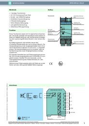
Mode Mode of of of Operation<br />
Operation<br />
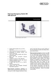
The pull rope emergency switch type NSR 01/02/<br />
03 is operated by a 50 m (max. 75 m) pull rope<br />
(steel rope, red plastic coated, dia. 5 mm) on<br />
each of the two sides. The triggering of the<br />
mechanism will be caused py pulling the pull<br />
rope.<br />
At an angular deviation from the mid position<br />
of about 6° ± 3° (activation <strong>for</strong>ce = 35 N ± 5 N)<br />
the patented switching mechanism is activated.<br />
This mechanism in turn suddenly activates the<br />
Pull Pull Rope Rope Arrangement, Arrangement, Version Version A<br />
A<br />
Pull Pull Rope Rope Rope Arrangement, Arrangement, Version Version B<br />
B<br />
control switches and cogently guides the<br />
switch lock into end stop position. The activated<br />
(pushed-down) position of the control<br />
switches can be unlocked only by the reset lever.<br />
The control switches feature a cogent separation<br />
characteristic and correspond to the international<br />
safety standard EN418. The NC contact<br />
(normally closed) opens the safety chain of the<br />
control and effects a switch-off of the subsequent<br />
device.<br />
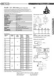
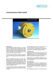
Accessoires:<br />
Accessoires:<br />
1 eye screw M6x60 4 rope eye 3/16" 7 pull rope: steel rope with red PVC sheathing<br />
2 turnbuckle M6x110 5 rope clamp 3/16" diameter 5mm<br />
3 spring RZ 168 6 wire loop M 8 x 80 weight 0,039 kg/m<br />
with bolt tensile strength 1600 N/mm˛<br />
8 spring bridge rope elongation 0,012 mm/m °C<br />
To ensure a safe switch-off when the rope is ruptured, both springs (3) must be pre-loaded to an extent,<br />
that the distance between the eyes amounts at least to 250 mm and the activation lever is in mid position:<br />
a) Rough adjustment at the rope end, b) refinement at the turnbuckle.<br />
distance between supports a [m] 2 2,5 3 3,5 4 5<br />
switching distance s [mm] ca. 280 310 340 360 390 430<br />
Mounting examples (A= without rope rupture protection, B= with rope rupture protection according to VDE 0113)