INCREMENTAL ENCODER MyInc - MEYER Industrie-Electronic ...
INCREMENTAL ENCODER MyInc - MEYER Industrie-Electronic ...
INCREMENTAL ENCODER MyInc - MEYER Industrie-Electronic ...

You also want an ePaper? Increase the reach of your titles
YUMPU automatically turns print PDFs into web optimized ePapers that Google loves.
Incremental Encoder<br />
Absolute Encoder<br />
Measuring<br />
Measur<br />
Driving<br />
Controlling<br />
Cont
. . . three<br />
companies,<br />
one service . . .<br />
INGENIEURBÜRO<br />
HERBERT <strong>MEYER</strong><br />
Systems for the Automation Industry<br />
<strong>MEYER</strong> INDUSTRIE-<br />
ELECTRONIC GMBH<br />
Components for the Automation Industry<br />
INGENIEURGESELLSCHAFT<br />
SACHVERSTÄNDIGER<br />
REVISIONSINGENIEURE MBH<br />
Inspection Company for Quality<br />
Assurance<br />
System Integrator and Engineering<br />
company for applications and systems<br />
Distribution of a wide range of components<br />
for the automation-, process-, machine<br />
building- and manufacturing industries<br />
Certified test laboratory for medical<br />
equipment and commercial building<br />
safety and quality tests
CONTENTS<br />
SELECTION GUIDE 3<br />
GENERAL OVERVIEW 7<br />
<strong>INCREMENTAL</strong> <strong>ENCODER</strong>S <strong>MyInc</strong>:<br />
Shaft encoder BINS24 Ø 24 mm 22<br />
Blind shaft encoder BINB24 Ø 24 mm 24<br />
Shaft encoder BINS37 Ø 37 mm 26<br />
Hollow shaft encoder BINH37 Ø 37 mm 28<br />
Shaft encoder AINS40/AINS40Z Ø 40 mm 31<br />
Hollow shaft encoder AINH40Z Ø 40 mm 32<br />
Shaft encoder AINS41 Ø 41 mm 33<br />
Universal industrial encoder BINS50/BINH50 Ø 50 mm 35<br />
Shaft and hollow shaft encoder FINS58/FINH58 Ø 58 mm 39<br />
Shaft encoder AINS58 Ø 58 mm 42<br />
Hollow shaft encoder AINH58 Ø 58 mm 44<br />
Hollow shaft encoder CINH76 Ø 76 mm 46<br />
Shaft encoder AINS90/AINS90S Ø 90 mm 48<br />
Shaft encoder FINS90 Ø 90 mm 50<br />
Hollow shaft encoder AINH90/AINH90S Ø 90 mm 52<br />
Hollow shaft encoder AINH95 Ø 95 mm 54<br />
Hollow shaft encoder DINH100 Ø 100 mm 56<br />
Hollow shaft encoder DINH145 Ø 145 mm 58<br />
OVERSPEED SWITCH AOSS90 60<br />
DRAW WIRE <strong>ENCODER</strong>S CDxx 62<br />
ABSOLUTE <strong>ENCODER</strong>S MyAbs:<br />
Shaft and hollow shaft encoder CAxx37 Ø 37 mm 64<br />
Shaft and hollow shaft encoder BAxx58 Ø 58 mm 67<br />
Shaft and blind shaft encoder CAxx58 Ø 58 mm 88<br />
Shaft and blind shaft encoder FAxx90 Ø 90 mm 94<br />
ACCESSORIES 102<br />
INSTALLATION INSTRUCTIONS 113<br />
Meyer <strong>Industrie</strong>-<strong>Electronic</strong> GmbH – MEYLE<br />
Carl-Bosch-Straße 8<br />
49525 Lengerich/Germany<br />
Tel.: +49 54 81-93 85-0<br />
Fax: +49 54 81-93 85-12<br />
Internet: www.meyle.de<br />
E-Mail: sales@meyle.de<br />
1
2<br />
Meyer <strong>Industrie</strong>-<strong>Electronic</strong> GmbH – MEYLE<br />
Carl-Bosch-Straße 8<br />
49525 Lengerich/Germany<br />
Tel.: +49 54 81-93 85-0<br />
Fax: +49 54 81-93 85-12<br />
Internet: www.meyle.de<br />
E-Mail: sales@meyle.de
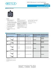
SELECTION GUIDE<br />
Incremental Encoders<br />
Version<br />
Type series<br />
Electrical characteristics<br />
Output<br />
Supply voltage (VDC)<br />
Mechanical characteristics<br />
Shaft Ø (mm)<br />
housing diameter (mm)<br />
max. speed (min -1 )<br />
max. shaft load radial/axial (N)<br />
max. working temp. (°C)<br />
Protection to<br />
Type of connection<br />
max. resolution<br />
highlights or product differentations<br />
page<br />
Incremental encoder<br />
shaft<br />
BINS24<br />
Push-pull<br />
5 ... 24 or 8 ... 30<br />
4/5/6<br />
24<br />
12000<br />
10/20<br />
–20 ... +85<br />
IP 64<br />
cable<br />
1080<br />
miniature version<br />
22<br />
Incremental encoder<br />
shaft<br />
AINS40/AINS40Z<br />
RS 422/Push-pull<br />
5 or 11 ... 30 or 5 ... 24<br />
6<br />
40<br />
12000<br />
20/10<br />
–20 ... +80<br />
IP 54<br />
cable<br />
2500/1024<br />
standard version<br />
31<br />
Incremental encoder<br />
hollow shaft<br />
BINB24<br />
Push-pull<br />
5 ... 24 or 8 ... 30<br />
4/6<br />
24<br />
12000<br />
–20 ... +85<br />
IP 64<br />
cable<br />
1024<br />
miniature hollow shaft<br />
version<br />
24<br />
Incremental encoder<br />
hollow shaft<br />
AINH40Z<br />
RS 422/Push-pull<br />
5 or 11 ... 30 or 5 ... 24<br />
6<br />
40<br />
12000<br />
20/10<br />
–20 ... +80<br />
IP 52<br />
cable<br />
1024<br />
standard hollow shaft<br />
version<br />
32<br />
Incremental encoder<br />
shaft<br />
BINS37<br />
RS 422/Push-pull<br />
5 or 5 ... 30<br />
4/5/6/8<br />
36,8<br />
6000<br />
20/10<br />
–20 ... +70<br />
IP 65/IP 67<br />
cable<br />
1024<br />
economical version<br />
26<br />
Incremental encoder<br />
shaft<br />
AINS41<br />
RS 422/Push-pull<br />
5 or 4, 75 ... 30<br />
6<br />
41<br />
6000<br />
20/30<br />
–20 ... +70<br />
IP 65<br />
cable<br />
2499<br />
economical version<br />
Meyer <strong>Industrie</strong>-<strong>Electronic</strong> GmbH – MEYLE<br />
Carl-Bosch-Straße 8<br />
49525 Lengerich/Germany<br />
33<br />
Tel.: +49 54 81-93 85-0<br />
Fax: +49 54 81-93 85-12<br />
Internet: www.meyle.de<br />
E-Mail: sales@meyle.de<br />
Incremental encoder<br />
hollow shaft<br />
BINH37<br />
RS 422/Push-pull<br />
5 or 5 ... 30<br />
4/5/6/8<br />
36,8<br />
6000<br />
–20 ... +70<br />
IP 65/IP 67<br />
cable<br />
1024<br />
economical hollow shaft<br />
version<br />
28<br />
Incremental encoder<br />
shaft<br />
BINS50/BINH50<br />
RS 422/Push-pull<br />
5 or 5 ... 30<br />
6/10/12 or 6/8/10/12/14/15<br />
50<br />
12000<br />
80/40<br />
–40 ... +85<br />
IP 65/IP 67<br />
cable<br />
3600<br />
Ø 50 mm housing,<br />
Ø 58 mm flange stable and<br />
robust bearing design<br />
35<br />
3
4<br />
SELECTION GUIDE<br />
Incremental Encoders<br />
Version<br />
Type series<br />
Electrical characteristics<br />
Output<br />
Supply voltage (VDC)<br />
Mechanical characteristics<br />
Shaft Ø (mm)<br />
housing diameter (mm)<br />
max. speed (min -1 )<br />
max. shaft load radial/axial (N)<br />
max. working temp. (°C)<br />
Protection to<br />
Type of connection<br />
max. resolution<br />
highlights or product differentations<br />
page<br />
Incremental Encoders<br />
Version<br />
Type series<br />
Electrical characteristics<br />
Output<br />
Supply voltage (VDC)<br />
Mechanical characteristics<br />
Shaft Ø (mm)<br />
housing diameter (mm)<br />
max. speed (min -1 )<br />
max. shaft load radial/axial (N)<br />
max. working temp. (°C)<br />
Protection to<br />
Type of connection<br />
max. resolution<br />
highlights or product differentations<br />
page<br />
Incremental encoder<br />
shaft and hollow shaft<br />
FINS58/FINH58<br />
RS 422/Push-pull/sine wave<br />
5 or 5 ... 30 or 4,75 ... 30<br />
6/10 or 6/8/10/12/14<br />
58<br />
9000/12000<br />
100/50<br />
–30 ... +100<br />
IP 65/IP 67<br />
cable, connector<br />
80000 (interpolatet)<br />
standard version<br />
Option: programmable sine<br />
wave output<br />
39<br />
Incremental encoder<br />
shaft<br />
AINS90/AINS90S<br />
RS 422/Push-pull<br />
5 or 11 ... 30<br />
11/12<br />
90<br />
6000<br />
200/100<br />
–20 ... +80<br />
IP 65<br />
cable, connector<br />
10000<br />
heavy duty<br />
high resolution<br />
48<br />
Incremental encoder<br />
shaft<br />
AINS58<br />
RS 422/Push-pull<br />
5 or 4, 75 ... 30<br />
6/10<br />
58<br />
8000<br />
38/40<br />
–20 ... +70<br />
IP 65<br />
cable, connector<br />
2499<br />
economical version<br />
Option: up to +100 °C<br />
42<br />
Incremental encoder<br />
shaft<br />
FINS90<br />
RS 422/Push-pull<br />
5 or 4, 75 ... 30<br />
6/12<br />
90<br />
6000<br />
50/60<br />
–20 ... +70<br />
IP 65<br />
cable, connector<br />
2499<br />
economical version<br />
heavy duty<br />
Option: up to +100 °C<br />
50<br />
Meyer <strong>Industrie</strong>-<strong>Electronic</strong> GmbH – MEYLE<br />
Carl-Bosch-Straße 8<br />
49525 Lengerich/Germany<br />
Tel.: +49 54 81-93 85-0<br />
Fax: +49 54 81-93 85-12<br />
Incremental encoder<br />
hollow shaft<br />
AINH58<br />
RS 422/Push-pull<br />
5 or 4, 75 ... 30<br />
6/10/12<br />
58<br />
6000<br />
–20 ... +70<br />
IP 65<br />
cable, connector<br />
2499<br />
economical version<br />
Option: up to +100 °C<br />
44<br />
Incremental encoder<br />
hollow shaft<br />
AINH90/AINH90S<br />
RS 422/Push-pull<br />
5 or 11 ... 30<br />
12/20/25/30/32<br />
90<br />
4500<br />
–20 ... +80<br />
IP 65<br />
cable, connector<br />
10000<br />
heavy duty hollow shaft<br />
52<br />
Internet: www.meyle.de<br />
E-Mail: sales@meyle.de<br />
Incremental encoder<br />
hollow shaft<br />
CINH76<br />
RS 422/Push-pull<br />
5 or 10 ... 30<br />
15 ... 42<br />
76<br />
6000<br />
–25 ... +100<br />
IP 40/IP 64<br />
cable<br />
10000<br />
large hollow shaft<br />
diameter<br />
46<br />
Incremental encoder<br />
hollow shaft<br />
AINH95<br />
RS 422/Push-pull<br />
5 or 4, 75 ... 30<br />
12/20/25<br />
90<br />
6000<br />
–20 ... +70<br />
IP 65<br />
cable, connector<br />
2499<br />
economical version<br />
heavy duty<br />
Option: up to +100 °C<br />
54
SELECTION GUIDE<br />
Incremental Encoders<br />
Version<br />
Type series<br />
Electrical characteristics<br />
Output<br />
Supply voltage (VDC)<br />
Mechanical characteristics<br />
Shaft Ø (mm)<br />
housing diameter (mm)<br />
max. speed (min -1 )<br />
max. shaft load radial/axial (N)<br />
max. working temp. (°C)<br />
Protection to<br />
Type of connection<br />
max. resolution<br />
highlights or product differentations<br />
page<br />
Absolute Encoders<br />
Version<br />
Type series<br />
Electrical characteristics<br />
Output<br />
Supply voltage (VDC)<br />
Mechanical characteristics<br />
Shaft Ø (mm)<br />
housing diameter (mm)<br />
max. speed (min -1 )<br />
max. shaft load radial/axial (N)<br />
max. working temp. (°C)<br />
Protection to<br />
Type of connection<br />
max. resolution<br />
highlights or product differentations<br />
page<br />
Incremental encoder<br />
hollow shaft<br />
DINH100<br />
RS 422/Push-pull<br />
4,75 ... 5,5 or 10 ... 30<br />
25 ... 45<br />
100<br />
3500<br />
200/100<br />
–10 ... +70<br />
IP 54<br />
cable, connector<br />
4096<br />
heavy duty<br />
large hollow shaft diameter<br />
56<br />
Incremental encoder<br />
hollow shaft<br />
DINH145<br />
RS 422/Push-pull<br />
4,75 ... 5,5 or 10 ... 30<br />
48 ... 72<br />
145<br />
800<br />
200/100<br />
–10 ... +70<br />
IP 54<br />
cable, connector<br />
2500<br />
heavy duty<br />
large hollow shaft diameter<br />
58<br />
Absolute encoder, singleturn and multiturn<br />
shaft, hollow and blind shaft<br />
CAxx37<br />
SSI/BiSS option SinCos<br />
5 or 7 ... 30<br />
6 or 8<br />
37,5<br />
12000<br />
–25 ... +100/–15 ... +120<br />
IP 64/IP 40<br />
cable, PCB connector<br />
29/31 Bits<br />
miniature version<br />
high temperature<br />
63<br />
Meyer <strong>Industrie</strong>-<strong>Electronic</strong> GmbH – MEYLE<br />
Carl-Bosch-Straße 8<br />
49525 Lengerich/Germany<br />
Tel.: +49 54 81-93 85-0<br />
Fax: +49 54 81-93 85-12<br />
Overspeed Switch<br />
AOSS90<br />
NO, NC<br />
240 VAC / 6 A<br />
11, 12<br />
90<br />
9000<br />
200/100<br />
–30 ... +130<br />
IP 66<br />
connector, terminal box<br />
4000<br />
heavy duty centrifugal<br />
overspeed switch; multiple<br />
mounting possibilities with<br />
incremental and absolute<br />
encoders<br />
60<br />
Internet: www.meyle.de<br />
E-Mail: sales@meyle.de<br />
Draw Wire<br />
CDxx<br />
see section<br />
incremental or absolute<br />
encoder<br />
62<br />
Absolute encoder, singleturn and multiturn<br />
shaft, hollow and blind shaft<br />
BAxx58<br />
SSI/BiSS/Profibus<br />
CANopen/CANlift<br />
5 or 10 ... 30<br />
6/10 or 10/12/14/15<br />
58/60<br />
12000/9000<br />
80/40<br />
–40 ... +90<br />
IP 65/IP 67<br />
cable connector<br />
29 Bit<br />
through hollow shaft version (SSI/BiSS)<br />
Safe operation in strong magnetic fields<br />
stable and robust bearing design<br />
67<br />
5
6<br />
SELECTION GUIDE<br />
Absolute Encoders<br />
Version<br />
Type series<br />
Electrical characteristics<br />
Output<br />
Supply voltage (VDC)<br />
Mechanical characteristics<br />
Shaft Ø (mm)<br />
housing diameter (mm)<br />
max. speed (min -1 )<br />
max. shaft load radial/axial (N)<br />
max. working temp. (°C)<br />
Protection to<br />
Type of connection<br />
max. resolution<br />
highlights or product differentations<br />
page<br />
Special versions<br />
Version<br />
Type series<br />
Electrical characteristics<br />
Output<br />
Supply voltage (VDC)<br />
Mechanical characteristics<br />
Shaft Ø (mm)<br />
housing diameter (mm)<br />
max. speed (min -1 )<br />
max. shaft load radial/axial (N)<br />
max. working temp. (°C)<br />
Protection to<br />
Type of connection<br />
max. resolution<br />
highlights or product differentations<br />
page<br />
Absolute encoder, singleturn and multiturn<br />
shaft and blind shaft<br />
CAxx58<br />
SSI/BiSS/Parallel/Profibus DP/Device Net/<br />
CANopen/Interbus<br />
5 or 10 ... 30<br />
6/10 or 10/12<br />
58<br />
12000<br />
60/40<br />
–40 ... +100<br />
IP 64/IP 67<br />
cable, connector<br />
29 Bit<br />
High temperature<br />
88<br />
Incremental encoder<br />
shaft<br />
DINS53<br />
RS 422/Push-Pull<br />
4,75 ... 5,5 or 10 ... 30<br />
6<br />
53<br />
6000<br />
20/10<br />
–10 ... +70<br />
IP 68<br />
cable, connector<br />
1500<br />
High protection class IP 68,<br />
easy mounting<br />
on request<br />
Incremental encoder<br />
shaft<br />
DINS58<br />
RS 422/Push-Pull<br />
4,75 ... 5,5 or 10 ... 30<br />
12<br />
58<br />
8000<br />
400/400<br />
–10 ... +70<br />
IP 65/IP 67<br />
cable, connector<br />
5000<br />
High shaft load<br />
on request<br />
Specifications are subject to change without notice.<br />
Due to RoHS EU directive 2002/95/EC, housings will be changed to lead free colours without further notice.<br />
For actual RoHS status please consult factory<br />
Meyer <strong>Industrie</strong>-<strong>Electronic</strong> GmbH – MEYLE<br />
Carl-Bosch-Straße 8<br />
49525 Lengerich/Germany<br />
Tel.: +49 54 81-93 85-0<br />
Fax: +49 54 81-93 85-12<br />
Absolute encode multiturn shaft and hollow shaft<br />
FAxx90<br />
SSI/Profibus/CANopen<br />
Parallel on request<br />
11 ... 30<br />
11/12 or 12/20/25/30<br />
90<br />
9000/6000<br />
200/100<br />
–20 ... +90<br />
IP 65/IP 67<br />
cable, connector<br />
29 Bit<br />
heavy duty<br />
large hollow shaft diameter<br />
94<br />
Absolute encoder,<br />
singleturn, taper shaft<br />
GAST37<br />
12/13 bits<br />
4,75 ... 5,25<br />
5,5; taper 1:3<br />
37<br />
12000<br />
–40 ... +115<br />
IP 40<br />
12 pin PCB connector<br />
13 Bit<br />
Absolute motor encoder<br />
Small dimensions<br />
Mounted stater coupling<br />
on request<br />
Internet: www.meyle.de<br />
E-Mail: sales@meyle.de<br />
Absolute encoder<br />
shaft<br />
MyA2<br />
analog<br />
15 ... 30<br />
6<br />
58<br />
12000<br />
20/10<br />
0 ... +70<br />
IP 65<br />
connector<br />
10 Bit<br />
analog output<br />
4–20 mA/0–10 V<br />
according to angle<br />
0–360°<br />
on request
GENERAL/OVERVIEW<br />
Introduction<br />
Description<br />
The optical rotary encoder is an angular position sensor. It is made source of light, light<br />
emitting diode (or LED), a receptor and a disk rotating in between. The optical disk with dark<br />
and clear radial lines is mounted on the rotating shaft of the encoder. Most of the disks used<br />
by Meyle are Polyfass (Mylar-Mica composite) and are unbreakable (see photo). The light<br />
from the LED crosses the lines on the disk and creates an analogical signal in the receptor,<br />
which is later amplified and could be converted in either square-wave or sine-cosine signals.<br />
All Meyle encoders use the differential reading, helping to compensate the reduction of the<br />
amplitude of the signals due to higher temperature, age, wearing of the bearings, etc.<br />
Incremental encoders simply count the number of pulses engraved on the disk and in case<br />
of power shut-down, it is necessary to find out the origin at every new start.<br />
Single-turn absolute encoders determine their position at all times using a single code in a<br />
given single revotution, even if there is no reference measurement.<br />
Multi-turn absolute encoders provide in addition a reading of the position within the revo -<br />
lution and is capable of counting the number of turns made.<br />
Applications<br />
Stop dog positioning Workpiece lengthmeasurement system with<br />
opto electric and encoder<br />
Crosstable positioning<br />
Valve position control Length dimension with measuring wheel Lengthmeasuring of textile or paper rolls<br />
Roboter axis control Fork hight measuring at fork trucks Positioning at CNC-tooling-machines<br />
Tensile stress control Control of transport vehicles Adjustment of lift platforms<br />
Meyer <strong>Industrie</strong>-<strong>Electronic</strong> GmbH – MEYLE<br />
Carl-Bosch-Straße 8<br />
49525 Lengerich/Germany<br />
Tel.: +49 54 81-93 85-0<br />
Fax: +49 54 81-93 85-12<br />
Internet: www.meyle.de<br />
E-Mail: sales@meyle.de<br />
7
8<br />
GENERAL/OVERVIEW<br />
General<br />
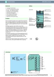
Conformity: All Meyle encoders fully comply with the<br />
CE-regulations and are intensively<br />
tested in our EMC laboratories. They<br />
High quality of signals: All encoders from Meyle, are equipped with<br />
ageing and temperature compensation to<br />
ensure a long term and stable signal also<br />
after many years of operation.<br />
Ageing compensation: Each LED source will inevitably lose it’s<br />
power over a period of time. As a result, the<br />
output signal degrades. The phase shift<br />
between channel A and B of 90° becomes<br />
Signals of a new encoder or encoders with<br />
ageing compensation:<br />
Benefit: The ageing compensation circuit<br />
ensures the same signal, even after many<br />
years of operating time. The down time of<br />
Meyer <strong>Industrie</strong>-<strong>Electronic</strong> GmbH – MEYLE<br />
Carl-Bosch-Straße 8<br />
49525 Lengerich/Germany<br />
Tel.: +49 54 81-93 85-0<br />
Fax: +49 54 81-93 85-12<br />
Channel A<br />
Channel B<br />
Temperature compensation: This specialised circuit ensures that the quality<br />
of the signal will stay on the same high<br />
level over the whole working temperature<br />
range.<br />
Environmental conditions: A significant influence on the lifetime of the<br />
encoder is set by the environment in which<br />
the encoder is operating, e.g.:<br />
The ambient temperature<br />
The expected shaft load<br />
The possible grade of dust/dirt and<br />
humidity/liquids<br />
Temperature: Working temperature:<br />
Definition according to<br />
DIN standards 32 878<br />
Is defined as the environmental temperature,<br />
in which the encoder will produce the signals<br />
defined in the data sheets.<br />
conform to CE requirements according to<br />
EN 50082-2, EN 50081-2 and EN 55011<br />
class B.<br />
less and less. The direction of rotation may<br />
no longer be detected. Properly by the<br />
control, a special electronic circuit, which is<br />
built in the specific ASIC prevents this effect.<br />
Signals of an older encoder without ageing<br />
compensation:<br />
machines will be reduced dramatically and<br />
the reliability is increased.<br />
Benefit:<br />
The positioning accuracy of a machine will<br />
not be affected by temperature changes.<br />
The support design and the use of high<br />
quality components makes our encoders<br />
suitable for applications in rough conditions.<br />
Many references such as from Bosch,<br />
Siemens, Bombardier and other customers<br />
proof these high requirements.<br />
Operating temperature:<br />
Is defined as the environmental temperature<br />
which the encoder can withstand without<br />
getting damaged.<br />
Internet: www.meyle.de<br />
E-Mail: sales@meyle.de
GENERAL/OVERVIEW<br />
General<br />
Dirt/dust and humidity/water: The IP classification according to EN 60529<br />
describes how the encoder is protected<br />
against particles and water. It is described as<br />
an abbreviation ”IP” followed by two<br />
numbers.<br />
The first digit defines the size of the particles.<br />
The higher the number the smaller the<br />
particles.<br />
Protection against particles<br />
(first digit):<br />
0 not protected<br />
1 protected against particles 50 mm and larger<br />
2 protected against particles 12,5 mm<br />
and larger<br />
3 protected against particles 2,5 mm and<br />
larger<br />
4 protected against particles 1,0 mm<br />
and larger<br />
5 protected against dust<br />
6 dust proof<br />
Designation of colours abbreviation colour<br />
to DIN standard 757<br />
BK black<br />
BN brown<br />
RD red<br />
OG orange<br />
YE yellow<br />
GN green<br />
BU blue<br />
Shaft Load: Due to misalignment and other mechanical<br />
influences from outside, the shaft of the<br />
encoder is exposed to a number of different<br />
loads. This has a direct impact on the lifetime<br />
of the ball bearings and also on the<br />
electrical signal itself. If there is an over -<br />
load there will be an early wear and in the<br />
worst case it will lead to a failure of the unit<br />
and to a destruction of the optical system<br />
inside.<br />
For shaft encoders the maximal radial and<br />
axial load should not be exceeded. It is<br />
highly recommended to use a coupling<br />
between the encoder shaft and the drive<br />
shaft, see also the accessories and the<br />
mounting suggestions.<br />
Meyer <strong>Industrie</strong>-<strong>Electronic</strong> GmbH – MEYLE<br />
Carl-Bosch-Straße 8<br />
49525 Lengerich/Germany<br />
Tel.: +49 54 81-93 85-0<br />
Fax: +49 54 81-93 85-12<br />
The second digit defines the resistance<br />
against water. The higher the number, the<br />
higher the water pressure can be.<br />
Our encoders have a protection up to IP 67.<br />
These two tables summarise the most used<br />
IP ratings:<br />
Protection against water<br />
(second digit)<br />
0 not protected<br />
1 protected against vertically falling drops of<br />
water<br />
2 protected against falling drops of<br />
water up to 15° from vertical<br />
3 protected against water sprayed up to 60°<br />
from vertical<br />
4 protected against water sprayed from all<br />
directions, limited ingress permitted<br />
5 protected against low pressure jets from all<br />
directions, limited ingress permitted<br />
6 protected against strong jets of water, e.g.<br />
for use on ship decks, limited ingress permit-<br />
ted<br />
7 protection against the affects of immersion<br />
between 15 cm and 1 m<br />
8 protected against long periods of<br />
immersion under pressure<br />
VT violet<br />
GY grey<br />
WH white<br />
PK pink<br />
GD gold<br />
TQ turquoise<br />
SR silver<br />
In the technical data sheets of the<br />
encoders, typical values for the radial and<br />
axial load at the shaft end are listed. This is<br />
based on the lifetime of the ball bearing, the<br />
speed, the mechanical load and the temperature.<br />
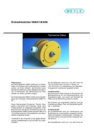
To easily find the lifetime for the specific<br />
application the following diagrams can be<br />
used. All of the diagrams are based on the<br />
following parameters:<br />
60° C environmental temperature<br />
The axial load is always half the load<br />
compared to the radial load<br />
Internet: www.meyle.de<br />
E-Mail: sales@meyle.de<br />
9
10<br />
GENERAL/OVERVIEW<br />
General<br />
Type series 58 mm diameter<br />
radial shaft load in N<br />
1 n = 3000 min -1<br />
2 n = 6000 min -1<br />
3 n = 9000 min -1<br />
4 n = 12000 min -1<br />
Bearing’s lifetime in years<br />
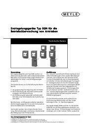
Incremental encoder<br />
Assembly and function:<br />
Meyer <strong>Industrie</strong>-<strong>Electronic</strong> GmbH – MEYLE<br />
Carl-Bosch-Straße 8<br />
49525 Lengerich/Germany<br />
radial shaft load in N<br />
Meyle encoders operate on an electro-optical<br />
scanning principle.<br />
A disk with a radial grating of lines and<br />
gaps rotates between a light source<br />
(mostly a LED) and a receiver which produces<br />
a sine wave signal proportional to<br />
the light received.<br />
Mask<br />
LED<br />
Tel.: +49 54 81-93 85-0<br />
Fax: +49 54 81-93 85-12<br />
Type series 90 mm diameter<br />
1 n = 2000 min -1<br />
2 n = 4000 min -1<br />
3 n = 6000 min -1<br />
Receiver<br />
Disk with radial lines<br />
and gaps<br />
Processing of the signals: The sine wave signals are processed fur -<br />
ther in an electronic circuitry, usually a<br />
specific ASIC. This is necessary because<br />
most controllers controls (like e.g. counters)<br />
require digital signals with a certain voltage<br />
Bearing’s lifetime in years<br />
level. For that the signals are pre-processed<br />
in the encoder. The pre-processed signals<br />
are transmitted by the output circuit depending<br />
on the application.<br />
Internet: www.meyle.de<br />
E-Mail: sales@meyle.de
GENERAL/OVERVIEW<br />
General<br />
Selecting an<br />
incremental<br />
encoder:<br />
When selecting the encoder, following<br />
parameters should be considered in addition<br />
to the topic mentioned on page 8–10.<br />
Number of channels: Encoders with one output channel<br />
Encoders with one output channel are used<br />
where no direction sensing is needed, e.g.<br />
Encoders with two output channels<br />
Applications, where the direction of a rotation<br />
should be sensed, e.g. positioning,<br />
require encoders with two channels A and<br />
B being shifted 90° out of phase.<br />
Encoders with three output channels<br />
In addition to the two channels A and B<br />
there is a zero signal available, that appears<br />
once per turn. This can be used e.g. as a<br />
Multiplication of pulses: The resolution of a two channel encoder can<br />
be multiplied by two or four using a special<br />
edge detecting.<br />
Inverted signals: When used in environments, with a lot of<br />
electrical noise and/or if very long cable distances<br />
are required, we recommend to use<br />
encoders with inverted (complementary)<br />
Resolution: Example: An encoder is equipped with a<br />
measuring wheel. Every revolution corresponds<br />
to a distance of 200 mm (circumference).<br />
The accuracy should be 0,1 mm.<br />
What is the required resolution (ppr)?<br />
Meyer <strong>Industrie</strong>-<strong>Electronic</strong> GmbH – MEYLE<br />
Carl-Bosch-Straße 8<br />
49525 Lengerich/Germany<br />
Tel.: +49 54 81-93 85-0<br />
Fax: +49 54 81-93 85-12<br />
speed control or length measuring.<br />
By detecting the phase shift, the direction<br />
can be located.<br />
Shaft turning clockwise, top-view of shaft<br />
Inverted signals available<br />
0-pulse is linked to AND with channel A<br />
and B<br />
t r = rise time<br />
t f = fall time<br />
reference signal during the first revolution<br />
after power up.<br />
An encoder with physically 5000 pulses per<br />
revolution can generate 20000 pulses per<br />
revolution using this technique<br />
signals. These signals are always available<br />
with output circuits of the RS 422 type and<br />
sine wave outputs. Meyle also offers them<br />
for push-pull outputs.<br />
Given: Circumference of the measuring<br />
wheel: U = 200 [mm]<br />
Accuracy of the system: G = 0,1 [mm]<br />
Wanted: Resolution of the encoder: A = ?<br />
[pulses/resolution]<br />
resolution = Circumference<br />
Accuracy<br />
Internet: www.meyle.de<br />
E-Mail: sales@meyle.de<br />
= U<br />
G<br />
The required resolution would be 2000 ppr<br />
(pulses per revolution).<br />
11
12<br />
GENERAL/OVERVIEW<br />
General<br />
Pulse frequency: The required pulse frequency can be calculated.<br />
This is based on the number of pulses<br />
per turn (ppr) and the speed (rpm). The max.<br />
pulse frequency is listed for each encoder.<br />
Usually it is 300 kHz. Meyle also offers high<br />
resolution encoders with a pulse frequency<br />
of up to 800 kHz.<br />
This diagram can be used for the<br />
most common resolutions as a quick<br />
guide:<br />
Outputs and voltage supplies<br />
(overview):<br />
required pulse frequency [kHz]<br />
350<br />
300<br />
250<br />
200<br />
150<br />
100<br />
Meyer <strong>Industrie</strong>-<strong>Electronic</strong> GmbH – MEYLE<br />
Carl-Bosch-Straße 8<br />
49525 Lengerich/Germany<br />
5000 ppr<br />
Tel.: +49 54 81-93 85-0<br />
Fax: +49 54 81-93 85-12<br />
Example<br />
of how to calculate the required pulse frequency<br />
fmax: Given: Speed n= 3000 min-1 Resolution of the encoder<br />
R = 1000 ppr<br />
f max = n x R<br />
60<br />
The required pulse frequency is 50 kHz. Now<br />
you can compare this result with the data of<br />
the encoder you would like to choose.<br />
50<br />
speed [min –1 0 2000 4000 6000 8000 10000 120000<br />
]<br />
Meyle offers a wide range of possible outputs and voltage supplies for any application.<br />
Output Inverted signals Voltage supply<br />
RS 422 Yes 5 V DC<br />
RS 422 Yes 10 ... 30 V DC or 5 ... 30 V DC<br />
Push Pull output No 10 ... 30 V DC or 5 ... 30 V DC<br />
Push Pull output Yes 10 ... 30 V DC or 5 ... 30 V DC<br />
Sine wave voltage output Yes 5 V DC<br />
Sine wave voltage output Yes 10 ... 30 VDC<br />
If the encoder is used in an environment with<br />
strong electrical noise and long cables we<br />
highly recommend the use of inverted<br />
signals.<br />
Sensor outputs: The sensor outputs are used if the distance<br />
from the encoder to the control unit is very<br />
long and the voltage supply at the encoder<br />
could drop due to this long distance.<br />
The input impedance of the sensor inputs<br />
(Controller) is very high, and the voltage drop<br />
2500 ppr<br />
on the sensor output line is almost zero. Due<br />
to this it is possible to detect the actual<br />
supply voltage of the encoder (e.g. 4,2 V<br />
instead of 5 V). Based on this information the<br />
controller will increase the voltage supply to<br />
e.g. 5,8 V.<br />
Internet: www.meyle.de<br />
E-Mail: sales@meyle.de<br />
1000 ppr<br />
500 ppr<br />
250 ppr
GENERAL/OVERVIEW<br />
General<br />
Digital outputs: The sine wave signal from the optical system<br />
is first digitised to have square wave signals<br />
available.<br />
Shaft turning clockwise, top view of shaft<br />
Inverted signals are available<br />
0-pulse is linked to AND with channel<br />
A and B<br />
To transmit the signals there are two possible<br />
outputs available. RS 422 (TTL compatible)<br />
or push-pull (covers PNP or NPN). For<br />
choosing the suitable output for the<br />
application the following points have to be<br />
considered:<br />
The corresponding unit / controller the<br />
encoder will be connected to<br />
Output circuit and recommended<br />
input circuit RS 422:<br />
Push-pull:<br />
Output circuit and recommended<br />
input circuit push-pull with inverted<br />
signals:<br />
Output circuit and recommended<br />
input circuit push-pull without<br />
inverted signals:<br />
encoder recommended<br />
input circuit<br />
RS 422:<br />
RS 422 line driver RS 422<br />
line receiver<br />
e.g. AM26 C 32<br />
Z = 120 Ω<br />
Push-pull outputs are suitable for count<br />
interface cards, electronic counters or PLC<br />
inputs.<br />
encoder recommended<br />
input circuit<br />
UB =<br />
10 ... 30 V DC<br />
A, B, 0<br />
A, B, 0<br />
integrated push-pull R L = 1 kΩ<br />
driver with automatic<br />
wave impedance adjustment<br />
(Z = 40 ... 150 Ω)<br />
Meyer <strong>Industrie</strong>-<strong>Electronic</strong> GmbH – MEYLE<br />
Carl-Bosch-Straße 8<br />
49525 Lengerich/Germany<br />
R L<br />
GND<br />
encoder recommended<br />
input circuit<br />
A, B, 0<br />
RL UB 2<br />
UB =<br />
10 ... 30 V DC<br />
GND<br />
Integrated push-pull<br />
driver with automatic<br />
RL = 1 kΩ<br />
wave impedance adjustment<br />
(Z = 40 ... 150 Ω)<br />
Tel.: +49 54 81-93 85-0<br />
Fax: +49 54 81-93 85-12<br />
The distance from the encoder to the<br />
receiver unit<br />
The sensitivity against electrical noise or<br />
other interferences.<br />
Internet: www.meyle.de<br />
E-Mail: sales@meyle.de<br />
13
14<br />
GENERAL/OVERVIEW<br />
General<br />
Sine wave outputs: The sine wave signals are available as voltage<br />
signals. They can be further processed<br />
and can be multiplied by a factor of usually<br />
10, 20, 50, 100, 400, 500, 1000 res. binary<br />
factors (512, 1024). Due to the interpolation<br />
of the two signals, which are 90° out of<br />
phase, a very high resolution can be achieved.<br />
This makes these kind of signals specially<br />
useful for applications where very high<br />
resolutions are required. Further they are<br />
very suitable for digital drives with a very<br />
slow and precise movement, e.g. for grinding<br />
machines or lifts and elevators.<br />
Output circuit and recommended<br />
input circuit for sine wave voltage<br />
signals:<br />
R a = 10 Ω Z = 120 Ω<br />
C 1 = 150 pF U 1 = U 0<br />
C 2 = 10 pF<br />
R 1 = 10 kΩ<br />
R 2 = 33 kΩ<br />
U 0 = 2,5 V ±0,5 V OPV: z.B. MC33074<br />
Cable length: Depending on the output circuit and the electrical noise the following cable lengths are recommended:<br />
Output circuit max. cable length Encoder connected<br />
to e.g.<br />
Push-pull without inverted<br />
signals 100 m counter/PLC<br />
Push-pull with inverted signals 250 m PLC/IPC 1 )<br />
RS 422 with inverted signals up to 1000 m PLC/IPC 1 )<br />
(> 50 m depending<br />
on frequency)<br />
Voltage sinus with inverted<br />
signals 50 m PLC/IPC 1 )<br />
1)IPC = industrial PC<br />
Annotations:<br />
Depending on the application the recommended cable length can be shorter, especially in<br />
areas with strong electrical noise.<br />
Always use shielded cables<br />
The core diameter of the signal cores should be ∅ 0,14 mm 2<br />
The core diameter of the voltage supply cores should be large enough depending on the<br />
cable length, that the voltage supply of the encoder is high enough and the signals do not<br />
go below the minimum levels!<br />
We strictly recommend the use of the cable types written down in the accessories.<br />
Meyer <strong>Industrie</strong>-<strong>Electronic</strong> GmbH – MEYLE<br />
Carl-Bosch-Straße 8<br />
49525 Lengerich/Germany<br />
Tel.: +49 54 81-93 85-0<br />
Fax: +49 54 81-93 85-12<br />
Shaft turning clockwise, top view of shaft<br />
0-pulse is generated once per turn<br />
encoder recommended<br />
input circuit<br />
Internet: www.meyle.de<br />
E-Mail: sales@meyle.de<br />
1 V /<br />
1 V /<br />
1 V /
GENERAL/OVERVIEW<br />
General<br />
Selecting an<br />
Absolute encoder<br />
Design and function:<br />
Absolute encoders have a disk with a digital<br />
coding on concentric tracks. This code is<br />
read by a Opto-Asic. A unique bit pattern is<br />
assigned to each position.<br />
The advantage is, that after power failure<br />
true position verification is available as soon<br />
as power is up again, even if the shaft was<br />
moved during the dead state.<br />
Selecting an absolute encoder: When selecting the right absolute encoder<br />
the following parameters should be considered<br />
in addition to the recomendations on<br />
page 8–10.<br />
Versions: Singleturn encoders:<br />
Depending on the number of divisions they<br />
genrate up to 131072 (17 Bit) unique per<br />
turn. This corresponds to an angular resolution<br />
of 0,0028°. After one revolution the<br />
process re-starts.<br />
Singleturn encoders can be used in appli -<br />
cations where revolution is sufficient, e.g.<br />
measurement of angles, robotic.<br />
Code types: Bit 1 (LSB)<br />
Binary Code:<br />
Bit 2<br />
Bit 3<br />
Bit 4 (MSB)<br />
Significance<br />
Gray Code: The Gray Code is a single-step code. This<br />
indicates, that from one position to the next<br />
only 1 bit is changed. The reliability of the<br />
code detection is increased, which leads to<br />
a high position-reliability.<br />
Symmetrically cut Gray Code<br />
(Gray-Excess):<br />
Bit 1 (LSB)<br />
Bit 2<br />
Bit 3<br />
Bit 4 (MSB)<br />
Significance<br />
0 1 2 3 4 5 6 7 8 9 10 11 12 13 14 15<br />
0 1 2 3 4 5 6 7 8 9 10 11 12 13 14 15<br />
Bit 1 (LSB)<br />
Bit 2<br />
Bit 3<br />
Bit 4 (MSB)<br />
Significance<br />
Reversion of the Gray Code: The code values increase when the shaft is<br />
turning clockwise. If the most significant bit<br />
Optical disk in Gray code<br />
0 1 2 3 4 5 6 7 8 9<br />
Meyer <strong>Industrie</strong>-<strong>Electronic</strong> GmbH – MEYLE<br />
Carl-Bosch-Straße 8<br />
49525 Lengerich/Germany<br />
Tel.: +49 54 81-93 85-0<br />
Fax: +49 54 81-93 85-12<br />
Advantage:<br />
No reference drives after starting-up are<br />
necessary as with incremental systems.<br />
Safety is increased and the time taken for<br />
reference drives is saved.<br />
Supply voltage<br />
Type of code<br />
Interface (SSI, parallel, fieldbus,<br />
4 ... 20 mA)<br />
Multiturn encoders:<br />
They are available with up to 131072 (17 Bit)<br />
definite angular positions per revolution and<br />
in addition 4096 (12 Bit) definite revolutions.<br />
This corresponds to 70 billion definite positions.<br />
Multiturn encoders can be used for posi -<br />
tioning applications e.g. automatic storage,<br />
retiered systems, lift elevators, cranes,<br />
machine tool, etc.<br />
The binary code can be processed very<br />
easily by computer systems. When using<br />
optical read-out, errors may occure, because<br />
the change from one bit to another on the<br />
different concentric tracks (LSB, LSB+1...) is<br />
not exactly synchronized. Due to this,<br />
without any correction of the code, the<br />
position information could be wrong.<br />
The gray code is used to opticaly read out<br />
the position for all absolute encoders<br />
The extraction of a defined part of the gray<br />
code leads to the gray-excess code. This<br />
code enables the generation of non binary<br />
based divisions, e.g. 360, 720, 1000, 1440.<br />
(MSB) is inverted, the code values decrease<br />
when the shaft is turning clockwise<br />
Internet: www.meyle.de<br />
E-Mail: sales@meyle.de<br />
Coded disk<br />
Multilayer PCB board<br />
Opto Asic<br />
15
16<br />
GENERAL/OVERVIEW<br />
Interface<br />
Outputs To transfer the position data to a controller,<br />
different interfaces are available.<br />
Parallel output: This type of transfer is very fast. All bits of a<br />
position are transferred simultaneously each<br />
via a separate line.<br />
Output circuit and recommended<br />
input circuit parallel interface:<br />
Synchronous Serial Interface (SSI): Compared to the parallel interface, the SSI<br />
interface needs less components and the<br />
SSI<br />
EMC-characteristics are much better. In<br />
Output circuit and recommended<br />
input circuit of the SSI-Interface:<br />
Synchronous-serial Transfer (SSI):<br />
encoder recommended<br />
input circuit<br />
Integrated push-pull driver<br />
encoder Recommended<br />
input circuit<br />
Optocoupler,<br />
e.g. 6N137<br />
RS 485<br />
Line driver<br />
R 1 , R 2 = 100 Ω<br />
C 1 = 1 nF<br />
Data +<br />
Data -<br />
Clock<br />
T = clock pulse period<br />
t m = storage time of monostable element<br />
t m ranging from 10 µs to 30 µs<br />
t v = 100 ns<br />
With the first shift of the clock signal from<br />
low to high " the most significant bit (MSB)<br />
of the angular data is applied to the shaft<br />
encoder’s serial output.<br />
With each succeeding rising edge, the next<br />
less significant bit is shifted to the data output.<br />
After transmission of the least significant bit<br />
(LSB) the Alarm bit or other special bits are<br />
transferred, depending on configuration.<br />
Then the data line switches to low § until the<br />
time t m has passed.<br />
Meyer <strong>Industrie</strong>-<strong>Electronic</strong> GmbH – MEYLE<br />
Carl-Bosch-Straße 8<br />
49525 Lengerich/Germany<br />
Tel.: +49 54 81-93 85-0<br />
Fax: +49 54 81-93 85-12<br />
addition less cores are needed for trans -<br />
mission and the possible cable length is<br />
much longer.<br />
The number of clock pulses necessary for<br />
data transfer is independent of the resolution<br />
of the absolute shaft encoder.<br />
The clock signal can be interrupted at any<br />
point, or continued in ring-register mode for<br />
repeated polling.<br />
A further transfer of data cannot be started<br />
until the data line switches to high $ again. If<br />
the clock pulse sequence is not interrupted<br />
at point §, the ring-register mode is activated<br />
automatically. This means that the data<br />
stored at the first clock pulse transition ! are<br />
returned to the serial input si via the terminal<br />
so. As long as the clock pulse is not interrupted<br />
at §, the data can be read out as<br />
often as wanted (multiple transfer).<br />
Internet: www.meyle.de<br />
E-Mail: sales@meyle.de
GENERAL/OVERVIEW<br />
Interface<br />
Cable length:<br />
Type of connection and recommended<br />
input circuit<br />
BiSS Sensor Communication<br />
Bi-directional and fully-digital<br />
Depending on the desired output circuit, we recommend following cable lengths:<br />
Interface and output circuit max. cable length Connected to<br />
Parallel CMOS/TTL 2 m PLC/IPC1 )<br />
Parallel push-pull 100 m PLC/IPC1 )<br />
SSI up to 1200 m PLC/IPC1 )<br />
RS 422 /RS 485<br />
1) IPC = Industrial PC<br />
(> 50 m depending on frequency)<br />
Notes:<br />
Depending on the application the max. allowed cable length can be shorter, especially in<br />
areas with strong electrical noise.<br />
Always use shielded cables<br />
The core diameter of the signal cores should be Ø 0,14 mm 2<br />
The core diameter of the voltage supply cores should be large enough depending on the<br />
cable length, that the voltage supply of the encoder is high enough and the signals do not<br />
go below the minimum levels!<br />
We strictly recommend the use of the cable types written down in the accessories.<br />
Connection – precautions For the connection of the shield braids, refer<br />
to the logic control documentation. In all<br />
cases, for grounding, the braids must be<br />
covered through 360<br />
SSI Transmission<br />
o . All unused conductors<br />
must be connected to the same<br />
potential at both ends.<br />
Keep the encoder connection cables as far<br />
away from the power cables as possible and<br />
avoid running them in parallel. Finally, for the<br />
same regulated power supply, only connect<br />
encoders drawing the current that the power<br />
supply can deliver. Group the signals of the<br />
same type by pair, CLK+ with CLK-, DATA+<br />
with DATA-.<br />
Shield<br />
BISS<br />
encoder recommended input circuit<br />
Encoder<br />
supply<br />
transducer<br />
+U B<br />
0 V<br />
l+<br />
l–<br />
BiSS is a fully-digital and bi-directional<br />
sensor interface. It defines communication<br />
between one master and several slaves<br />
(sensors) in industrial control systems. BiSS<br />
manifests a new standard in technology and<br />
is available license-free (GPL). Due to its high<br />
performance, it constitutes an efficient alternative<br />
to the standard combination of data<br />
interface and analog sine/cosine incremental<br />
output.<br />
Meyer <strong>Industrie</strong>-<strong>Electronic</strong> GmbH – MEYLE<br />
Carl-Bosch-Straße 8<br />
49525 Lengerich/Germany<br />
Tel.: +49 54 81-93 85-0<br />
Fax: +49 54 81-93 85-12<br />
Internet: www.meyle.de<br />
E-Mail: sales@meyle.de<br />
+<br />
–<br />
+<br />
–<br />
Twisted<br />
Pair<br />
voltage supply<br />
10 ... 30 V DC<br />
PLC<br />
BiSS only needs a total of 6 lines (4 data,<br />
2 power), does not require any hardware for<br />
analog signals (cable(s)/drive interpolation<br />
electronics) – and so helps to reduce system<br />
costs.<br />
Bus Networking:<br />
Up to 8 sensors can be connected to a<br />
bus-master. Wiring and control cost is considerably<br />
reduced for multi axe applications.<br />
17
18<br />
GENERAL/OVERVIEW<br />
General<br />
Bus systems: The use of a network of sensor-actuator bus<br />
systems has essential advantages:<br />
Reduced expenditure concerning connection:<br />
All members are linked by one cable.<br />
Wide range diagnostics and programming<br />
possibility of the units.<br />
In the following please find the available bus<br />
systems:<br />
CAN: CAN fullfils the real time demands of the<br />
automobile industries (ABS, Airbag,<br />
CANopen<br />
Motormanagement)<br />
Multi-Master system<br />
The message text (speed, position...) itself<br />
is marked by an identifier through the<br />
whole network, instead of indexing the<br />
nodes.<br />
Meyer <strong>Industrie</strong>-<strong>Electronic</strong> GmbH – MEYLE<br />
Carl-Bosch-Straße 8<br />
49525 Lengerich/Germany<br />
Tel.: +49 54 81-93 85-0<br />
Fax: +49 54 81-93 85-12<br />
Check for importance of message<br />
Accept or ignore ® network wide broadcasting<br />
high allocation on the network<br />
Monitoring (high reliability)<br />
Bus Specification according to CAN High<br />
Speed ISO/DIN 11898 for transmission<br />
rates of up to 1 Mbaud.<br />
Introduction The Meyle CANopen encoder is an absolute messages which is of importance for this<br />
encoder. The version described sends its station. The identifier transmitted with the<br />
current position to another station via the message is the basis for the decision as to<br />
"CAN-bus" transmission medium (physically: whether the message will be accepted or<br />
screened and twisted two-wire line).<br />
not.<br />
The serial bus system CAN (Controller Area The bus coupler is standardised according<br />
Network), which had been originally devel- to the international standard ISO-DIS 11898<br />
oped for automotive uses, is gaining ground (CAN High Speed) and allows data to be<br />
in industrial automation technology. The transferred at a maximum rate of 1 MBit/s.<br />
system is multimaster compatible, i.e. sev - The most significant feature of the<br />
eral CAN- stations are able to request the CAN-protocol is its high level of transmission<br />
bus at the same time. The data transfer is reliability (Hamming distance = 6). The CANregulated<br />
by the message's priority. The Controller Intel 82527 used in the encoder is<br />
message with the highest priority (deter- basic as well as full-CAN compatible and<br />
mined by the identifier) will be received supports the CAN-specification 2.0 part B<br />
immediately. Within the CAN system, there (standard protocol with 11-bit- identifier as<br />
are message identifiers but no transport well as extended protocol with 29-bit<br />
addresses. The message which is being sent<br />
can be received by all stations at the same<br />
time (broadcast). By means of a special filter<br />
method, the station only accepts the relevant<br />
identifier).<br />
Field of application In applications, where the position of a drive<br />
or of other parts of a machine has to be<br />
recorded and signalled to the control<br />
system, the encoder can carry out this<br />
function. The encoder can resolve, for<br />
instance, positioning tasks by sending the<br />
check-back signal concerning the present<br />
drive position via the CAN bus to the<br />
positioning unit.<br />
Internet: www.meyle.de<br />
E-Mail: sales@meyle.de<br />
®<br />
CANopen
GENERAL/OVERVIEW<br />
General<br />
The CANopen Profile CANopen allows for:<br />
synchronisation of the devices,<br />
auto-configuration of the network,<br />
comfortable access to all device parameters.<br />
Existing Profiles The following device profiles already exist:<br />
CiA Draft Standard Proposal 401 for<br />
Input/Output Modules<br />
CiA Draft Standard Proposal 402 for Drives<br />
and Motion Control<br />
CiA Work Item 403 for Human-Machine<br />
Interfaces<br />
The encoder device profile<br />
(CIA DSP 406)<br />
CANopen uses four communication objects<br />
(COB) with different features:<br />
Process Data Objects (PDO) for real-time<br />
data<br />
Service Data Objects (SDO) for the transfer<br />
of parameters and programs<br />
Network Management (NMT, Life-<br />
Guarding)<br />
predefined objects (for synchronisation,<br />
time stamp, emergency message)<br />
This profile describes a standardised and<br />
binding, but manufacturer-independent definition<br />
of the interface for encoders. The profile<br />
not only defines which CANopen functions<br />
are to be used, but also how they are<br />
to be used. This standard allows an open<br />
and manufacturer-independent bus system.<br />
The device profile consists of two object categories<br />
the standard category C1 describes all the<br />
basic functions the shaft encoder must<br />
contain<br />
DATA Transmission<br />
In CANopen, the data is transferred by<br />
means of two different communication types<br />
(COB = Communication Object) with different<br />
features:<br />
Process Data Objects (PDO)<br />
Service Data Objects (SDO)<br />
The priority of the message objects is<br />
determined by the COB identifier.<br />
The process data objects (PDO) serve the<br />
highly dynamic exchange of real-time data<br />
(e.g. position of the shaft encoder) with a<br />
maximum length of 8 Byte.<br />
Meyer <strong>Industrie</strong>-<strong>Electronic</strong> GmbH – MEYLE<br />
Carl-Bosch-Straße 8<br />
49525 Lengerich/Germany<br />
Tel.: +49 54 81-93 85-0<br />
Fax: +49 54 81-93 85-12<br />
simultaneous data input and output.<br />
cyclical and event-controlled process data<br />
processing,<br />
All device parameters are stored in an object<br />
directory. The object directory contains the<br />
description, data type and structure of the<br />
parameters as well as their addresses<br />
(index).<br />
The directory consists of three parts:<br />
communication<br />
profile parameters,<br />
device profile parameters and manufacturer<br />
specific parameters.<br />
CiA Work Draft 404 for Closed-Loop<br />
Controllers and Transformers<br />
CiA Work Item 405 for IEC-1131 Interfaces<br />
CiA Draft Standard Proposal 406 for<br />
Encoders<br />
CiA Work Item 407 for Public Transport<br />
CiA Work Item 408 for Fork-Lifts<br />
the extended category C2 contains a variety<br />
of additional functions which either<br />
have to be supported by category C2 shaft<br />
encoders (mandatory) or which are optional.<br />
Category C2 devices thus contain all C1<br />
and C2 mandatory functions as well as,<br />
depending on the manufacturer, further<br />
optional functions. In addition, an addressable<br />
area is defined in the profile, to which,<br />
depending on the manufacturer, different<br />
functions can be assigned.<br />
This data is transferred with high priority<br />
(low COB identifier). PDOs are broadcast<br />
messages and put their information simultaneously<br />
at the disposal of all desired<br />
receivers. The service data objects (SDO)<br />
form the communication channel for the<br />
transfer of device parameters (e.g.<br />
programming of the shaft encoder's<br />
resolution). Since these parameters are<br />
transferred acyclically (e.g. only once when<br />
starting up the network), the SDO objects<br />
have a low priority (high COB identifier).<br />
Internet: www.meyle.de<br />
E-Mail: sales@meyle.de<br />
19
20<br />
GENERAL/OVERVIEW<br />
General<br />
Profibus: General Information The basic functions of the PROFIBUS DP<br />
are only described in extracts in here.<br />
®<br />
For additional information, please refer to<br />
Introduction The Meyle Profibus encoders are absolute<br />
encoders. The version described sends its<br />
current position to another station via the<br />
transmission medium "PROFIBUS DP"<br />
(physically: screened and twisted pair line).<br />
The Profibus encoder supports all class 1<br />
and 2 functions listed in the encoder profile.<br />
PROFIBUS-DP is standardised and binding,<br />
but manufacturer-independent definition for<br />
a variety of applications in the field of production,<br />
process and automation. The<br />
requirements of openness and independence<br />
from the manufacturer are stipulated in<br />
the European standard EN 50 170.<br />
Field of application In systems, where the position of a drive or<br />
of any other part of a machine has to be<br />
recorded and transmitted to the control<br />
system, the encoder is doing this function.<br />
The encoder can resolve, for instance,<br />
Basic function of the Profibus DP The central control system (master) cyclically<br />
reads out the input information from the<br />
slaves and transmits the output information<br />
to the slaves. For this purpose, the bus cycle<br />
time has to be shorter than the program<br />
cycle time of the central control system<br />
(e.g. SPC, or IPC), which amounts to approx.<br />
10 ms for several applications. Beside the<br />
PROFIBUS DP Basic Functions<br />
Transmission technology:<br />
RS-485 twisted pair line<br />
Baud rates ranging from 9.6 kbit/s up<br />
to 12 Mbit/s<br />
Bus access:<br />
Monomaster or multimaster systems<br />
possible<br />
Token passing procedure between the<br />
masters and master-slave procedures<br />
for slaves<br />
Master and slave devices, max. of<br />
126 stations at a single bus<br />
Communication:<br />
Point-to-point (user data communication)<br />
or multicas (control commands)<br />
Cyclical master-slave user data communication<br />
and acyclical master-master<br />
data transfer<br />
Operating state:<br />
Operate: cyclical transfer of input and<br />
output data<br />
Stop: only master-master data transfer is<br />
possible<br />
Clear: The input data are read, the output<br />
data remain in the safe status<br />
Synchronisation: Control commands<br />
enable a synchronisation of the input<br />
and output data<br />
Sync mode: Output data are being synchronised<br />
Functionality:<br />
Address assignment for the DP slaves via<br />
the bus<br />
Cyclical user data transfer between DP<br />
master and DP slave(s)<br />
Configuration of the DP master (DPM1)<br />
via the bus<br />
Single DP slaves are dynamically<br />
activated or deactivated<br />
Control of the DP slave's configuration.<br />
Powerful diagnostic functions, 3 stepped<br />
diagnostic message levels.<br />
Meyer <strong>Industrie</strong>-<strong>Electronic</strong> GmbH – MEYLE<br />
Carl-Bosch-Straße 8<br />
49525 Lengerich/Germany<br />
Tel.: +49 54 81-93 85-0<br />
Fax: +49 54 81-93 85-12<br />
the standards on PROFIBUS DP, i.e.<br />
DIN 19245-3 and EN 50170 respectively.<br />
PROFIBUS-DP permits the communication<br />
of devices produced by different manufacturers<br />
without any particular adaptations of<br />
the interfaces. PROFIBUS DP is a special<br />
standard version for a quick data exchange<br />
within the field level which has been optimised<br />
in terms of speed and low connection<br />
costs. Central with local field devices like<br />
drives, valves, or encoders. The data<br />
exchange between these devices is pre -<br />
dominantly cyclical. The communication<br />
functions required for this exchange are<br />
determined by the functions of the<br />
PROFIBUS DP according to the EN 50 170<br />
European standard.<br />
positioning tasks by sending the feedback<br />
signal concerning the present drive position<br />
via the PROFIBUS DP to the positioning unit.<br />
cyclical user data transfer, the PROFIBUS<br />
DP version also disposes of powerful<br />
functions for diagnosis and initial operation<br />
procedures. The data traffic is controlled by<br />
watchdog functions on both the slave and<br />
the master side. In the following the basic<br />
functions of the PROFIBUS DP are<br />
summarised in short.<br />
Maximum of 246 byte input and output<br />
data per DP slave possible<br />
Synchronisation of in- and/ or output<br />
Protection functions:<br />
Access protection of the DP slaves' input/<br />
output<br />
All messages are transferred with a hamming<br />
distance of HD=4<br />
Response control at the DP slaves<br />
Monitoring of the user data communication<br />
with adjustable control timer at the master<br />
Device types:<br />
DP master class 2 (DPM2), e.g. programming/<br />
project planning devices<br />
DP master class 1 (DPM1), e.g. central<br />
automation devices like SPC, PC<br />
DP slave e. g. devices with binary or analogue<br />
input/output, drives, valves<br />
Internet: www.meyle.de<br />
E-Mail: sales@meyle.de
GENERAL/OVERVIEW<br />
General<br />
Diagnostic function The extensive diagnostic functions of<br />
PROFIBUS DP allow a quick localisation of<br />
possible errors. The diagnostic messages<br />
System Performance To ensure a high level of exchangeability<br />
between the devices, the system performance<br />
of PROFIBUS DP has also been standardised.<br />
It is mainly determined by the<br />
operational status of the DPM1. The DPM1<br />
can either be controlled locally or via the bus<br />
by the project planning device. The following<br />
three main states are available:<br />
Operate<br />
The DPM1 has entered the data transfer<br />
phase. In case of a cyclical data traffic, the<br />
input is read by the DP slaves while the output<br />
is transferred to the DP slaves. After an<br />
error has occurred during the data transfer<br />
phase of the DPM1, like for example, the<br />
failure of a DP slave, the response of the<br />
system is determined by the operating<br />
parameter "Auto Clear". If this parameter has<br />
Cyclical data transfer between DPM1<br />
and the DP SLAVES<br />
The data traffic between the DPM1 and the<br />
respective DP slaves is automatically<br />
handled by the DPM1 in a fixed, recurring<br />
order. When configuring the bus system, the<br />
user assigns a DP slave to the DPM1. In<br />
addition<br />
the slaves are in- or excluded from the user<br />
data communication. The data traffic<br />
between the DPM1 and the DP slaves is<br />
subdivided in three phases: parameterisation,<br />
configuration, and data transfer.<br />
Before including a DP slave in the data<br />
transfer phase, the DPM1 checks during the<br />
parameterisation and configuration phase,<br />
Meyer <strong>Industrie</strong>-<strong>Electronic</strong> GmbH – MEYLE<br />
Carl-Bosch-Straße 8<br />
49525 Lengerich/Germany<br />
Tel.: +49 54 81-93 85-0<br />
Fax: +49 54 81-93 85-12<br />
are transmitted by means of the bus and are<br />
joined together at the master.<br />
been set to true, the DPM1 will set the output<br />
of all the respective DP slaves to the safe<br />
status, as soon as a DP slave is no longer<br />
available for user data communication.<br />
Afterwards, the DPM1 changes to the clear<br />
status. If this parameter is = false, the DPM1<br />
remains, even if an error occurs, in the operate<br />
status, and the user can determine the<br />
response of the system at his own decision.<br />
Stop<br />
There is no data traffic between DPM1 and<br />
the DP slaves.<br />
Clear<br />
The DPM1 reads the input information of the<br />
DP slaves and maintains the safe status of<br />
the DP slaves' output.<br />
whether the planned set configuration cor -<br />
responds to the actual configuration of the<br />
device. For this check, the device type, the<br />
information on the format and the length as<br />
well as the number of input and output lines<br />
have to be correct. Due to this check it is<br />
ensured that the parameterisation is reliable<br />
and correct at the end. In addition to the<br />
user communication, which is automatically<br />
executed by the DPM1, the user can request<br />
the new parameterisation data to be sent to<br />
the DP slaves.<br />
Internet: www.meyle.de<br />
E-Mail: sales@meyle.de<br />
21
22<br />
<strong>INCREMENTAL</strong> <strong>ENCODER</strong> <strong>MyInc</strong> BINS24<br />
Low price at high performance<br />
IP 64<br />
Wide temperature range (-20 ... +85 °C)<br />
Housing is resistant against<br />
environmental influences due to<br />
chromium plated surface<br />
Sturdy cable output with multiple<br />
clamping<br />
Temperature compensation<br />
Broad input voltage range<br />
(5 ... 24 V or 8 ... 30 V)<br />
Mechanical characteristics:<br />
Highly flexible cable with stands<br />
constant flexing from 0 °C ... 70 °C<br />
Low power consumption despite high<br />
scanning rate<br />
Reverse connection protected and<br />
short-circuit proof<br />
Speed: max. 12 000 min -1<br />
Rotor moment of inertia: appr. 0,1 x 10⁻⁶ kgm 2<br />
Starting torque: < 0,001 Nm<br />
Radial load capacity of shaft: 10 N<br />
Axial load capacity of shaft:. 20 N<br />
Weight: appr. 0,06 kg<br />
Protection acc. to EN 60529: IP 64<br />
Working temperature: –20° C ... +85 °C<br />
Shaft: stainless steel<br />
Shock resistance acc. to DIN-IEC 68-2-27: 1000 m/s 2 , 6 ms<br />
Vibration resistance acc. to DIN-IEC 68-2-6: 100 m/s 2 , 55 ... 2000 Hz<br />
Electrical characteristics:<br />
Output circuit: Push-pull Push-pull<br />
Supply voltage: 5 ... 24 V DC 8 ... 30 V DC<br />
Power consumption (no load): max. 50 mA max. 50 mA<br />
Permissible load/channel: max. 50 mA max. 50 mA<br />
Pulse frequency: max. 160 kHz max. 160 kHz<br />
Signal level high: min. U B = –2,5 V min. U B = –3 V<br />
Signal level low: max. 0,5 V max. 2,5 V<br />
Rise time t r : max. 1 µs max. 1 µs<br />
Fall time t f : max. 1 µs max. 1 µs<br />
Short circuit proof outputs: DIN-IEC 68-2-27: yes yes<br />
Conforms to CE requirements acc. to EN 50082-2, EN 50081-2 and EN 55011 Class B<br />
Applications:<br />
Pick and place machines<br />
Handling machines for electronic components<br />
Quality testing machines<br />
Medical machines<br />
Meyer <strong>Industrie</strong>-<strong>Electronic</strong> GmbH – MEYLE<br />
Carl-Bosch-Straße 8<br />
49525 Lengerich/Germany<br />
!<br />
Mail opening and mail stuffing machines<br />
Check weighers<br />
Labeling machines<br />
Mole machines (camera control)<br />
Tel.: +49 54 81-93 85-0<br />
Fax: +49 54 81-93 85-12<br />
Pulse rates available at short notice:<br />
10, 25, 36, 50, 60, 100, 125, 180, 200, 250,<br />
360, 500, 512, 1000, 1024, 1080<br />
Internet: www.meyle.de<br />
E-Mail: sales@meyle.de
<strong>INCREMENTAL</strong> <strong>ENCODER</strong> <strong>MyInc</strong><br />
Terminal assignment<br />
Signal: 0V +UB A A B B 0 O<br />
Colour: WH BN GN YE GY PK BU RD<br />
without inverted signal: WH BN GN YE GY<br />
Insulate unused outputs before initial startup.<br />
Dimensions:<br />
Flange type 1<br />
(Ø 24 mm)<br />
Flange type 2<br />
(Ø 30 mm)<br />
Flange type 3<br />
(Ø 28 mm)<br />
A<br />
Flange type 2 3<br />
A ø 30 mm ø 28 mm<br />
B 3 mm 2 mm<br />
ORDERING CODE<br />
BINS24<br />
Flange<br />
1 = Ø 24 mm<br />
2 = Ø 30 mm<br />
3 = Ø 28 mm<br />
3<br />
Shaft Ø<br />
1 = Ø 4 mm x 10 mm<br />
2 = Ø 6 mm x 10 mm<br />
3 = Ø 5 mm x 10 mm<br />
with flattening<br />
Meyer <strong>Industrie</strong>-<strong>Electronic</strong> GmbH – MEYLE<br />
Carl-Bosch-Straße 8<br />
49525 Lengerich/Germany<br />
Output and voltage supply<br />
A1 = Push-pull (with<br />
inverted signals)<br />
5 ... 24 V DC<br />
supply voltage<br />
A5 = Push-pull (with<br />
inverted signals)<br />
8 ... 30 V supply<br />
voltage<br />
Tel.: +49 54 81-93 85-0<br />
Fax: +49 54 81-93 85-12<br />
Internet: www.meyle.de<br />
E-Mail: sales@meyle.de<br />
BINS24<br />
Connection<br />
3A = Cable axial<br />
(2 m PVC-cable)<br />
3R = Cable radial<br />
(2 m PVC-cable)<br />
Mounting advice:<br />
Do not connect<br />
encoder and drive<br />
rigidly to one<br />
another at shafts<br />
and flanges! Always<br />
use couplings to<br />
prevent shaft overload<br />
(see chapter<br />
accessories).<br />
Resolution<br />
1080 max.<br />
23
24<br />
<strong>INCREMENTAL</strong> <strong>ENCODER</strong> <strong>MyInc</strong><br />
Low price at high performance<br />
IP 64<br />
Wide temperature range (-20 ... +85 °C)<br />
Housing is resistant against environmental<br />
influences due to chromium plated<br />
surface<br />
Sturdy cable output with multiple<br />
clamping<br />
Temperature compensation<br />
Broad input voltage range<br />
(5 ... 24 V or 8 ... 30 V)<br />
Mechanical characteristics:<br />
Highly flexible cable with stands<br />
constant flexing at 0 °C ... 70 °C<br />
Low power consumption despite high<br />
scanning rate<br />
Reverse connection protected and<br />
short-circuit proof<br />
Speed: max. 12000 min -1<br />
Rotor moment of inertia: appr. 0,1 x 10 -6 kgm 2<br />
Starting torque: < 0,001 Nm<br />
Weight: appr. 0,06 kg<br />
Protection acc. to EN 60 529: IP 64<br />
Working temperature: –20 °C ... +85 °C<br />
Shaft: stainless steel<br />
Shock resistance acc. to DIN-IEC 68-2-27: 1000 m/s 2 , 6 ms<br />
Vibration resistance acc. to IEC 68-2-6: 100 m/s 2 , 55 ... 2000 Hz<br />
Electrical characteristics:<br />
Output circuit: Push-pull Push-pull<br />
Supply voltage: 5 ... 24 V DC 8 ... 30 V DC<br />
Power consumption (no load): max. 50 mA max. 50 mA<br />
Permissible load/channel: max. 50 mA max. 50 mA<br />
Pulse frequency: max. 160 kHz max. 160 kHz<br />
Signal level high: min. U B = –2,5 V min. U B = –3 V<br />
Signal level low: max. 0,5 V max. 2,5 V<br />
Rise time t r : max. 1 µs max. 1 µs<br />
Fall time t f : max. 1 µs max. 1 µs<br />
Short circuit proof outputs: yes yes<br />
Conforms to CE requirements acc. to EN 50082-2, EN 50081-2 and EN 55011 Class B<br />
Applications:<br />
Pick and place machines<br />
Handling machines for electronic components<br />
Quality testing machines<br />
Medical machines<br />
Meyer <strong>Industrie</strong>-<strong>Electronic</strong> GmbH – MEYLE<br />
Carl-Bosch-Straße 8<br />
49525 Lengerich/Germany<br />
!<br />
Mail opening and mail stuffing machines<br />
Check weighers<br />
Labeling machines<br />
Mole machines (camera control)<br />
Tel.: +49 54 81-93 85-0<br />
Fax: +49 54 81-93 85-12<br />
Internet: www.meyle.de<br />
E-Mail: sales@meyle.de<br />
BINB24<br />
Pulse rates available at short notice:<br />
10, 25, 36, 50, 60, 100, 125, 180, 200, 250,<br />
360, 500, 512, 1000, 1024<br />
Other pulse rates on request
<strong>INCREMENTAL</strong> <strong>ENCODER</strong> <strong>MyInc</strong><br />
Terminal assignment<br />
Signal: 0V +UB A A B B 0 O<br />
Colour: WH BN GN YE GY PK BU RD<br />
without inverted signal: WH BN GN YE GY<br />
Insulate unused outputs before initial startup.<br />
Meyer <strong>Industrie</strong>-<strong>Electronic</strong> GmbH – MEYLE<br />
Carl-Bosch-Straße 8<br />
49525 Lengerich/Germany<br />
Tel.: +49 54 81-93 85-0<br />
Fax: +49 54 81-93 85-12<br />
Internet: www.meyle.de<br />
E-Mail: sales@meyle.de<br />
BINB24<br />
Dimensions Mounting advice:<br />
Do not connect encoder and drive rigidly to<br />
one another at shafts and flanges! Always<br />
use couplings to prevent shaft overload (see<br />
chapter accessories).<br />
ORDERING CODE<br />
BINB24<br />
4 x M3 DIN 915-SW1,5<br />
Flange<br />
1 = Ø 24 mm<br />
Shaft Ø<br />
1 = Ø 4 mm Blind shaft<br />
2 = Ø 6 mm Blind shaft<br />
Output and voltage supply<br />
A1 = Push-pull (with<br />
inverted signals)<br />
5 ... 24 V DC supply<br />
voltage<br />
A5 = Push-pull (with<br />
inverted signals)<br />
8 ... 30 V supply<br />
voltage<br />
Connection<br />
3A = Cable axial<br />
(2 m PVC-cable)<br />
3R = Cable radial<br />
(2 m PVC-cable)<br />
Resolution<br />
1024 max.<br />
25
26<br />
<strong>INCREMENTAL</strong> <strong>ENCODER</strong> <strong>MyInc</strong><br />
Economical version<br />
Compact size only ø 37 x 33 mm<br />
Temperature- and ageing compensation<br />
Short circuit proof outputs<br />
Resolution up to 1024 ppr;<br />
Protection up to IP 67<br />
Flange and cover made from a new High-<br />
Tech-Material (composite material)<br />
High component integration leeds to low<br />
profile design, high performance and<br />
economical pricing<br />
“Tube Tech ® ” cable outlet guarantees<br />
10 x higher strain relief than traditional<br />
cabling methods<br />
Protection IP 67<br />
1 ½” (37 mm) diameter housing suitable<br />
for replacing resolvers.<br />
Meyer <strong>Industrie</strong>-<strong>Electronic</strong> GmbH – MEYLE<br />
Carl-Bosch-Straße 8<br />
49525 Lengerich/Germany<br />
!<br />
Mechanical characteristics:<br />
Speed: max. 6000 min-1 Rotors moment of inertia: appr. 0,4 x 10⁻⁶ kgm2 Starting torque: < 0,007 Nm<br />
Radial load capacity of the shaft: 20 N<br />
Axial load capacity of the shaft: 10 N<br />
Weight: appr. 0,1 kg<br />
Protection acc. to EN 60 529: bearing, shaft: IP 65<br />
cable outlet: IP 67<br />
Working temperature: –20 °C up to +70 °C1)3) Materials: shaft: stainless steel;<br />
housing, flange: composite PPA, 40 % KF (carbon fiber)<br />
cable: PVC<br />
Shock resistance acc. to DIN-IEC 68-2-27: 1000 m/s2 , 6 ms<br />
Vibration resistance acc. to DIN-IEC 68-2-6: 100 m/s2 , 10 ... 2000 Hz<br />
1) At push pull output and Supply voltage >15 V DC: max. 55 °C<br />
3) Higher temperatures up to 100 °C on request<br />
Electrical characteristics:<br />
Output circuit: RS 422<br />
(TTL-compatible)<br />
Push-pull<br />
Supply voltage: 5 V (±5%) 5 ... 30 V DC<br />
Power consumption (no load) typ. 70 mA / typ. 70 mA/<br />
with inverted signal: max. 100 mA max.120 mA<br />
Permissible load/channel: max. ±20 mA max. ±20 mA<br />
Pulse frequency: max. 250 kHz max. 250 kHz<br />
Signal level high: min. 2,5 V min. UB –2,5 V<br />
Signal level low: max. 0,5 V max. 0,5 V<br />
Rise time tr : max. 200 ns max. 1 µs<br />
Fall time tf : max. 200 ns max. 1 µs<br />
Short circuit proof outputs1): yes2) yes<br />
Reverse connection protection at UB : no no<br />
Conforms to CE requirements acc. to EN 50082-2, EN 50081-2 and EN 55011 Class B<br />
1) When supply voltage correctly applied<br />
2) Only one channel at a time:<br />
(at UB = 5 V short circuit to channel, 0 V, or +UB is permitted).<br />
Applications:<br />
– Substitute for resolvers<br />
– Packaging machines<br />
– Electrical machines<br />
– Vehicles<br />
– Conveyers, elevators<br />
– Semiconducter machines e.g. pick &<br />
place, cutting ...<br />
– Material handling<br />
– Special machines.<br />
Tel.: +49 54 81-93 85-0<br />
Fax: +49 54 81-93 85-12<br />
Internet: www.meyle.de<br />
E-Mail: sales@meyle.de<br />
BINS37<br />
Pulse rates available at short notice:<br />
10, 50, 60, 100, 180, 200, 250, 300, 360,<br />
400, 500, 512, 600, 1024<br />
Other pulse rates available on request
<strong>INCREMENTAL</strong> <strong>ENCODER</strong> <strong>MyInc</strong><br />
Signal: 0 V +U B A A B B 0 0 Shield<br />
Colour: WH BN GN YE GY PK BU RD<br />
Using RS 422 outputs and long cable distances, a wave<br />
impedance has to be applied at each cable end.<br />
Dimensions:<br />
ORDERING CODE<br />
BINS37<br />
Flange<br />
1 = Ø 36,8 mm<br />
Insulate unused outputs before initial startup.<br />
Shaft Ø<br />
1 = Ø 4 mm<br />
2 = Ø 5 mm<br />
3 = Ø 6 mm<br />
4 = Ø 1/4“<br />
6 = Ø 8 mm<br />
1<br />
Meyer <strong>Industrie</strong>-<strong>Electronic</strong> GmbH – MEYLE<br />
Carl-Bosch-Straße 8<br />
49525 Lengerich/Germany<br />
Cable 1, 2, 3 or 5 m long<br />
Output and voltage display Connection<br />
A2 = RS 422: 5 V DC ±5 3A = Cable* axial<br />
%<br />
(1 m PVC-cable)<br />
A5 = Push-pull with 3R = Cable* radial<br />
inverted signals:<br />
5 ... 30 V DC<br />
(1 m PVC-cable)<br />
Tel.: +49 54 81-93 85-0<br />
Fax: +49 54 81-93 85-12<br />
Internet: www.meyle.de<br />
E-Mail: sales@meyle.de<br />
BINS37<br />
Mounting advice:<br />
Do not connect the<br />
encoder and drive<br />
rigidly to one<br />
another at the shaft<br />
and flange! Always<br />
use a coupling to<br />
prevent shaft<br />
overload (see<br />
chapter<br />
accessories).<br />
Resolution<br />
1024 max.<br />
* “Tube Tech ® ” cable outlet guarantees 10 x higher strain relief than<br />
traditional cabling methods plus higher IP-Protection.<br />
Other cable lengths on request.<br />
27
28<br />
<strong>INCREMENTAL</strong> <strong>ENCODER</strong> <strong>MyInc</strong><br />
Economical version<br />
Compactunit size only ø 37 x 32 mm<br />
Very easy mounting. The encoder is<br />
mounted directly on the drive shaft<br />
without couplings. This saves up to 30 %<br />
cost and 60 % clearance compared to<br />
shaft versions.<br />
Temperature- and ageingcompensation<br />
Short circuit proof outputs<br />
Resolution up to 1024 ppr<br />
Protection up to IP 67<br />
Flange and cover made from a new<br />
High-Tech-Material (composite material)<br />
High component integration leeds to low<br />
profile design, high performance and economical<br />
pricing<br />
“Tube Tech ® ” cable outlet guarantees 10 x<br />
higher strain relief than traditional cabling<br />
methods plus higher IP-Protection.<br />
Also secures a protection of IP 67<br />
1 ½” (37 mm) diameter housing suitable for<br />
replacing resolvers.<br />
Meyer <strong>Industrie</strong>-<strong>Electronic</strong> GmbH – MEYLE<br />
Carl-Bosch-Straße 8<br />
49525 Lengerich/Germany<br />
!<br />
Tel.: +49 54 81-93 85-0<br />
Fax: +49 54 81-93 85-12<br />
BINH37<br />
Mechanical characteristics: Pulse rates available at short notice:<br />
Speed: max. 6000 min -1<br />
Rotors moment of inertia: appr. 1,4 x 10 -6 kgm 2<br />
Starting torque: < 0,01 Nm<br />
Weight: appr. 0,1 kg<br />
Protection acc. to EN 60 529: bearing, shaft: IP 65<br />
cable outlet: IP 67<br />
Working temperature: –20° C up to +70 °C 1)3)<br />
Materials: shaft: stainless steel;<br />
housing, flange: composite PPA, 40 % KF (carbon fiber)<br />
cable: PVC<br />
Shock resistance acc. to DIN-IEC 68-2-27: 1000 m/s 2 , 6 ms<br />
Vibration resistance acc. to DIN-IEC 68-2-6: 100 m/s 2 , 10 ... 2000 Hz<br />
1) At push pull output and Supply voltage > 15 V DC: max. 55 °C<br />
3) Higher temperatures up to 100 °C on request<br />
Electrical characteristics:<br />
Output circuit: RS 422<br />
(TTL-compatible)<br />
Push-pull<br />
Supply voltage: 5 V (±5%) 5 ... 30 V DC<br />
Power consumption (no load) typ. 70 mA / typ. 70 mA/<br />
with inverted signal: max. 100 mA max.120 mA<br />
Permissible load/channel: max. ±20 mA max. ±20 mA<br />
Pulse frequency: max. 250 kHz max. 250 kHz<br />
Signal level high: min. 2,5 V min. UB –2,5 V<br />
Signal level low: max. 0,5 V max. 0,5 V<br />
Rise time tr : max. 200 ns max. 1 µs<br />
Fall time tf : max. 200 ns max. 1 µs<br />
Short circuit proof outputs1) : yes2) yes<br />
Reverse connection protection at UB : no no<br />
Conforms to CE requirements acc. to EN 50082-2, EN 50081-2 and EN 55011 Class B<br />
1) When supply voltage correctly applied<br />
2) Only one channel at a time:<br />
(at UB = 5 V short circuit to channel, 0 V, or +UB is permitted).<br />
Applications:<br />
– Substitute for resolvers<br />
– Packaging machines<br />
– Electrical machines<br />
– Vehicles<br />
– Conveyers, elevators<br />
– Semiconducter machines e.g pick & place,<br />
cutting ...<br />
– Material handling<br />
– Special machines.<br />
10, 50, 100, 180, 200, 250, 300, 360, 400,<br />
500, 512, 600, 1024<br />
Other pulse rates available on request<br />
Internet: www.meyle.de<br />
E-Mail: sales@meyle.de
<strong>INCREMENTAL</strong> <strong>ENCODER</strong> <strong>MyInc</strong><br />
Terminal assignment<br />
Signal: 0 V +UB A A B B 0 0 Shield<br />
Colour: WH BN GN YE GY PK BU RD<br />
Using RS 422 outputs and long cable distances, a wave<br />
impedance has to be applied at each cable end.<br />
Dimension<br />
Short torque stop version;<br />
Long torque stop version is dashed<br />
Stator couppling version<br />
Insulate unused outputs before initial startup.<br />
1 cable length 1, 2, 3 or 5 m<br />
2 Slot for support torque, 3 mm deep<br />
3 Recommended pin for long torque stop Cyl. pin acc. to DIN 7 ø 4 mm<br />
Meyer <strong>Industrie</strong>-<strong>Electronic</strong> GmbH – MEYLE<br />
Carl-Bosch-Straße 8<br />
49525 Lengerich/Germany<br />
Tel.: +49 54 81-93 85-0<br />
Fax: +49 54 81-93 85-12<br />
BINH37<br />
Internet: www.meyle.de<br />
E-Mail: sales@meyle.de<br />
29
30<br />
<strong>INCREMENTAL</strong> <strong>ENCODER</strong> <strong>MyInc</strong><br />
Mounting advice:<br />
1<br />
Cyl.-pin to DIN 7 ø 4 mm<br />
ORDERING CODE<br />
BINH37<br />
Flange<br />
1 = Hollow shaft<br />
with short<br />
torque stop<br />
2 = Hollow shaft<br />
with long<br />
torque stop<br />
5 = Hollow shaft<br />
with stator<br />
coupling<br />
1) Do not connect the encoder and drive<br />
rigidly to one another at the shaft and<br />
flange!<br />
2) To mount a hollow shaft encoder, we<br />
recommend the use of a pin and with<br />
torque stop slot or a stator coupling.<br />
Meyer <strong>Industrie</strong>-<strong>Electronic</strong> GmbH – MEYLE<br />
Carl-Bosch-Straße 8<br />
49525 Lengerich/Germany<br />
Tel.: +49 54 81-93 85-0<br />
Fax: +49 54 81-93 85-12<br />
BINH37<br />
3) When mounting the encoder ensure<br />
that Lmin. is greater than the axial play<br />
of the drive.<br />
When using the long torque stop, a<br />
greater axial play is possible.<br />
Max. permissible drive shaft impact:<br />
(measuring error ≤ ± 0,5 bit and 4 times evaluate in the sequential electronic).<br />
Shaft Ø<br />
Mounting with stator coupling Mounting with<br />
torque support<br />
Pulses: Permissible axial Permissible radial Permissible radial<br />
impact impact impact<br />
up to 1024: ±0.4 mm ±0.09 mm ±0.075 mm<br />
1 = Ø 4 mm<br />
2 = Ø 5 mm<br />
3 = Ø 6 mm<br />
4 = Ø 1/4“<br />
6 = Ø 8 mm<br />
Output circuit and Supply<br />
voltage<br />
A2 = RS 422: 5 V DC ±5<br />
%<br />
A5 = Push-pull (with<br />
inverted signals)<br />
5 ... 30 V DC<br />
Connection<br />
3A = Cable* radial<br />
(1 m PVC-cable)<br />
3R = Cable* radial<br />
(2 m PVC-cable)<br />
* “Tube Tech ® ” cable outlet guarantees 10 x higher strain relief than<br />
traditional cabling methods plus higher IP-Protection.<br />
Other cable lengths available on request.<br />
Internet: www.meyle.de<br />
E-Mail: sales@meyle.de<br />
Resolution<br />
1024 max.
<strong>INCREMENTAL</strong> <strong>ENCODER</strong> <strong>MyInc</strong><br />
AINS40/AINS40Z<br />
• Up to 10.000 steps<br />
in 2500 cpt<br />
• Applications:<br />
micro-robotics, printing…<br />
O R D E R I N G C O D E<br />
S P E C I F I C A T I O N S<br />
AINS40 AINS40Z<br />
• COVER Aluminium Zinc alloy<br />
• BODY Aluminium Zinc alloy<br />
• SHAFT Stainless steel Stainless steel<br />
• TORQUE 0,2 Ncm 0,2 Ncm<br />
• WEIGHT 110 g 100 g<br />
AINS40<br />
AINS40Z<br />
Shaft Ø<br />
06 = 6 mm<br />
• MAX. SPEED 12 000 min-1 • RADIAL SHAFT LOADING 20 N<br />
• AXIAL SHAFT LOADING 10 N<br />
• INERTIA 10 gcm2 • PROTECTION IP 54<br />
Output circuit<br />
2 = 5 V RS422<br />
5 = 11-30 V Driver<br />
9 = 5-24 V Driver<br />
!<br />
Output signals<br />
9= A, A, B, B, 0, 0<br />
7= A, A, B, B<br />
5= A, A<br />
A= Index gated on A<br />
N= Index ungated<br />
Meyer <strong>Industrie</strong>-<strong>Electronic</strong> GmbH – MEYLE<br />
Carl-Bosch-Straße 8<br />
49525 Lengerich/Germany<br />
AINS403A<br />
AINS403R<br />
AINS40Z3R<br />
Tel.: +49 54 81-9385-0<br />
Fax: +49 54 81-9385-12<br />
AINS40<br />
AINS40Z<br />
D I M E N S I O N S<br />
Connection<br />
AINS40 :<br />
3A = shielded cable,<br />
axial output<br />
3R = shielded cable,<br />
radial output<br />
AINS40Z :<br />
3R = shielded cable,<br />
radial output<br />
Internet: www.meyle.de<br />
E-Mail: sales@meyle.de<br />
Resolution<br />
AINS40 : 2500 max<br />
AINS40Z : 1024 max<br />
31
32<br />
<strong>INCREMENTAL</strong> <strong>ENCODER</strong> <strong>MyInc</strong><br />
• Easy mounting by flexible<br />
anti-rotation blade<br />
• Applications:<br />
micro-robotics, DC motors<br />
shears…<br />
•<br />
COVER Zinc alloy<br />
•<br />
BODY Zinc alloy<br />
•<br />
SHAFT Aluminium<br />
•<br />
TORQUE 0.25 Ncm<br />
•<br />
WEIGHT 100 g<br />
O R D E R I N G C O D E<br />
AINH40Z<br />
S P E C I F I C A T I O N S<br />
Shaft Ø<br />
06 = 6 mm<br />
• MAX. SPEED 12 000 min-1 • RADIAL SHAFT LOADING 20 N<br />
• AXIAL SHAFT LOADING 10 N<br />
• INERTIA 5 gcm2 • PROTECTION IP 52<br />
Output circuit<br />
2 = 5 V RS422<br />
5 = 11-30 V Driver<br />
9 = 5-24 V Driver<br />
Output signals<br />
!<br />
9= A, A, B, B, 0, 0<br />
7= A, A, B, B<br />
5= A, A<br />
A= Index gated on A<br />
N= Index ungated<br />
Meyer <strong>Industrie</strong>-<strong>Electronic</strong> GmbH – MEYLE<br />
Carl-Bosch-Straße 8<br />
49525 Lengerich/Germany<br />
3R<br />
Tel.: +49 5481-9385-0<br />
Fax: +49 5481-9385-12<br />
AINH40Z<br />
D I M E N S I O N S<br />
Connection<br />
3R = shielded cable,<br />
radial output<br />
Internet: www.meyle.de<br />
E-Mail: sales@meyle.de<br />
Resolution<br />
1024 max
<strong>INCREMENTAL</strong> <strong>ENCODER</strong> <strong>MyInc</strong><br />
fslaklösjdlöaskjdflösjdfklöaöjdfklsjdfklsfjd-<br />
Miniature Size Ø 41 mm<br />
klsdjfklsdjflkösjdfklösdjfklsdjfsölkjdflskjfk<br />
IP 65 Protection<br />
lösjfdkla Synchro Flange Mounting<br />
4.75 to 30 Volts, RS 422 Compatible<br />
300 kHz Maximum Frequency<br />
Resolutions up to 2499<br />
Economical version<br />
Electrical<br />
Specifications<br />
Mechanical<br />
Specifications<br />
Output Signals<br />
Carl-Bosch-Straße 8<br />
49525 Lengerich/Germany<br />
!<br />
Supply Voltage 4.75-30 VDC<br />
Current Consumption 40 mA (max.)<br />
Output Circuit Push-Pull, RS 422A<br />
Impulse Frequency 100 kHz (max.)<br />
Logic Level (high) Vcc - 0.7 Volt<br />
Logic Level (low) 0.25 Volt (max.)<br />
Short Circuit Protection 100 %<br />
Cover Aluminium<br />
Body Aluminium<br />
Shaft Stainless steel<br />
Speed 6000 RPM (max.)<br />
Torque > 0.04 Nm<br />
Loading Axial 30 N, Radial 20 N<br />
Protection IP 65<br />
Temperature -20 °C . . . +70 °C<br />
Weight 140 g<br />
Meyer <strong>Industrie</strong>-<strong>Electronic</strong> GmbH – MEYLE<br />
Tel.: +49 54 81-93 85-0<br />
Fax: +49 54 81-93 85-12<br />
Internet: www.meyle.de<br />
E-Mail: sales@meyle.de<br />
AINS41<br />
33
34<br />
<strong>INCREMENTAL</strong> <strong>ENCODER</strong> <strong>MyInc</strong><br />
Connections<br />
Function Cable Colours, 3A, 3B<br />
0 Volt white<br />
+ Volt brown<br />
A green<br />
B yellow<br />
0 grey<br />
A pink<br />
B blue<br />
0 red<br />
ORDERING CODE<br />
AINS41<br />
Shaft Ø<br />
06 = 6 mm<br />
Output Circuit<br />
A5 = Push Pull<br />
4.75 to 30 VDC<br />
A2 = Line Driver 5 VDC,<br />
RS 422<br />
Meyer <strong>Industrie</strong>-<strong>Electronic</strong> GmbH – MEYLE<br />
Carl-Bosch-Straße 8<br />
49525 Lengerich/Germany<br />
Output Signals<br />
9 = A+B+0+<br />
Compliments<br />
Tel.: +49 54 81-93 85-0<br />
Fax: +49 54 81-93 85-12<br />
Connection<br />
3A = shielded cable, 2 m,<br />
axial output<br />
3R = shielded cable, 2 m,<br />
radial output<br />
Internet: www.meyle.de<br />
E-Mail: sales@meyle.de<br />
AINS41<br />
Resolution<br />
2499 max.
<strong>INCREMENTAL</strong> <strong>ENCODER</strong> <strong>MyInc</strong><br />
• Universal industrial encoder<br />
• ø 50 mm housing, ø 58 mm flange<br />
• Resolution up to 5000 cpt<br />
• Protection up to IP 67<br />
• 300 kHz Maximum Frequency<br />
• Stabile and robust design to withstand<br />
high shock and vibration<br />
Mechanical characteristics:<br />
Speed IP 65 1) : max. 12000 min -1<br />
Speed IP 67 2) : max. 6000 min -1<br />
Rotors moment of inertia: BINS50/BINH50 appr. 1.8 x 10 -6 kgm 2 /appr. 6 x 10 -6 kgm 2<br />
Starting torque: < 0.01 Nm, IP 65<br />
< 0.05 Nm, IP 67<br />
Radial load capacity shaft: BINS50 80 N<br />
Axial load capacity shaft: BINS50 40 N<br />
Weight: appr. 0.4 kg<br />
Protection acc. to EN 60 529 without shaft sealing: IP 65<br />
Protection acc. to EN 60 529 with shaft sealing: IP 67<br />
Working temperature: –40° C 3) ... +85 °C<br />
Shaft: BINS50/BINH50 stainless steel, h8/h7<br />
Shock resistance acc. to DIN-IEC 68-2-27: 2500 m/s 2 , 6 ms<br />
Vibration resistance to DIN-IEC 68-2-6: 100 m/s 2 , 10 ... 2000 Hz<br />
1) For continuous operation max. 6000 min -1<br />
2) For continuous operation max. 3000 min -1<br />
Electrical characteristics:<br />
3) With connector: -40 °C,<br />
cable fixed: -30 °C, cable moved: -20 °C<br />
Output circuit: RS 422 Push-Pull<br />
(TTL-Compatible) (7272)<br />
Supply voltage: 5 V ±5% 5 ... 30 V DC<br />
Power consumption (no load) typ. 40 mA typ. 50 mA<br />
max. 90 mA max.100 mA<br />
Permissible load/channel: max. ±20 mA max. ±20 mA<br />
Pulse frequency: max. 300 kHz max. 300 kHz 3)<br />
Signal level high: min. 2.5 V min. U B –2.0 V<br />
Signal level low: max. 0.5 V max. 0.5 V<br />
Rise time t r : max. 200 ns max. 1 µs<br />
Fall time t f : max. 200 ns max. 1 µs<br />
Short circuit proof outputs 1) : yes 2) yes<br />
Reverse connection protection at U B : no no<br />
Conforms to CE requirements acc. to EN 61000-6-2, EN 61000-6-3 and EN 61000-6-4<br />
1) If supply voltage correctly applied<br />
2) Only one channel allowed to be shorted-out:<br />
(If U B = 5 V, short-circuit to channel, 0 V, or +U B is permitted).<br />
(If U B = 5-30 V, short-circuit to channel or 0 V is permitted).<br />
3) Max. recommended cable length 30 m<br />
Meyer <strong>Industrie</strong>-<strong>Electronic</strong> GmbH – MEYLE<br />
Carl-Bosch-Straße 8<br />
49525 Lengerich/Germany<br />
!<br />
Tel.: +49 54 81-93 85-0<br />
Fax: +49 54 81-93 85-12<br />
BINS50<br />
BINH50<br />
Robust double bearing design<br />
Pulse rates available at a short notice:<br />
1, 5, 10, 12, 36, 60, 100, 200, 250, 256, 360,<br />
400, 500, 512, 600, 800, 1000, 1024, 1200,<br />
1250, 2000, 2048, 2500, 3600, 4096, 5000<br />
Other pulse rates available on request<br />
Internet: www.meyle.de<br />
E-Mail: sales@meyle.de<br />
35
36<br />
<strong>INCREMENTAL</strong> <strong>ENCODER</strong> <strong>MyInc</strong><br />
Terminal assignment<br />
Meyer <strong>Industrie</strong>-<strong>Electronic</strong> GmbH – MEYLE<br />
Carl-Bosch-Straße 8<br />
49525 Lengerich/Germany<br />
Tel.: +49 54 81-93 85-0<br />
Fax: +49 54 81-93 85-12<br />
BINS50<br />
BINH50<br />
Signal: 0 V +U B 0 V +Ub A A B B Z Z Shield<br />
GND Sens Sens<br />
M23, 12 pin connector, Pin: 10 12 11 2 5 6 8 1 3 4 – 1)<br />
M12, 8 pin connector, Pin: 1 2 3 4 5 6 7 8 – 1)<br />
MIL (MS styled), 10 pin con. Pin: F D E A G B H C I J 1)<br />
Cable colour: WH BN GY PK RD BU GN YE GY PK BU RD Shield<br />
1) Shields is attached to connector housing<br />
Top view of mating side, male contact base:<br />
Dimensioned drawing<br />
BINS 50<br />
Synchronous bracket<br />
Ø 58 mm<br />
M12, M23 and cable versions<br />
(Bracket type S5 and S7)<br />
Insulate unused outputs before initial startup<br />
Type<br />
View<br />
8 pin M12 connector 12 pin M23 connector MIL-Connector 10 pin<br />
BINS 50<br />
Clamping bracket<br />
Ø 58 mm<br />
M12, M23 and cable versions<br />
(Bracket type K5 and K7)<br />
1<br />
1<br />
M4, 6 deep<br />
M3, 6 deep<br />
MIL-connector version<br />
MIL-connector version<br />
Internet: www.meyle.de<br />
E-Mail: sales@meyle.de
<strong>INCREMENTAL</strong> <strong>ENCODER</strong> <strong>MyInc</strong><br />
Dimensioned drawing<br />
BINH 50<br />
Bracket with long torque stop<br />
Ø 50.8 mm<br />
M12, M23 connectors and cable versions<br />
(Bracket type H5 and H7)<br />
Mounting note:<br />
Bracket with stator coupling<br />
Pitch circle Ø 65 mm<br />
(Bracket type N5 and N7)<br />
cyl. pin DIN 7 Ø 4<br />
1<br />
2<br />
M3, 6 deep<br />
Torque stop slot<br />
Recommendation: cyl. pin acc. DIN 7 Ø 4<br />
Meyer <strong>Industrie</strong>-<strong>Electronic</strong> GmbH – MEYLE<br />
Carl-Bosch-Straße 8<br />
49525 Lengerich/Germany<br />
Tel.: +49 54 81-93 85-0<br />
Fax: +49 54 81-93 85-12<br />
BINS50<br />
BINH50<br />
MIL-connector version<br />
Internet: www.meyle.de<br />
E-Mail: sales@meyle.de<br />
37
38<br />
<strong>INCREMENTAL</strong> <strong>ENCODER</strong> <strong>MyInc</strong><br />
Dimensioned drawing<br />
BINH 50<br />
Bracket with tether arm<br />
(Bracket type T5 and T7)<br />
Bracket with stator coupling<br />
Pitch circle Ø 63 mm<br />
(Bracket type O5 and O7)<br />
O R D E R I N G C O D E<br />
BINS50<br />
shaft<br />
BINH50<br />
hollow<br />
shaft<br />
Shaft Ø<br />
06 = 6 mm<br />
10 = 10 mm<br />
12 = 12 mm<br />
06 = 6 mm<br />
08 = 8 mm<br />
10 = 10 mm<br />
12 = 12 mm<br />
14 = 14 mm<br />
15 = 15 mm<br />
Meyer <strong>Industrie</strong>-<strong>Electronic</strong> GmbH – MEYLE<br />
Carl-Bosch-Straße 8<br />
49525 Lengerich/Germany<br />
Tel.: +49 54 81-93 85-0<br />
Fax: +49 54 81-93 85-12<br />
BINS50<br />
BINH50<br />
Flange, Protection<br />
Output circuit Output Signals Connection<br />
Resolution<br />
S5 = Synchro, IP 65 (shaft)<br />
A5 = Push-pull 9 = A+B+0+Compliments 3R = shielded cable, 5000 max.<br />
S7 = Synchro, IP 67 (shaft)<br />
5 to 30 VDC<br />
1 m, radial output<br />
K5 = Clamping, IP 65 (shaft) A2 = Line Driver<br />
8R = 12 pin connector,<br />
K7 = Clamping, IP 67 (shaft)<br />
5 VDC RS 422<br />
M23, radial output,<br />
H5 = Torque stop, IP 65 (hollow shaft)<br />
CCW<br />
H7 = Torque stop, IP 67 (hollow shaft)<br />
N5 = Stator coupling pcd 65 mm, IP 65<br />
(hollow shaft)<br />
N7 = Stator coupling pcd 65 mm, IP 67<br />
(hollow shaft)<br />
O5 = Stator coupling pcd 63 mm, IP 65<br />
(hollow shaft)<br />
O7 = Stator coupling pcd 63 mm, IP 67<br />
(hollow shaft)<br />
T5 = Tether arm, IP 65 (hollow shaft)<br />
T7 = Tether arm, IP 67 (hollow shaft)<br />
10R = 10 pin MIL<br />
connector, radial<br />
output<br />
12R = 8 pin connector,<br />
M12, radial output,<br />
CW<br />
Internet: www.meyle.de<br />
E-Mail: sales@meyle.de
<strong>INCREMENTAL</strong> <strong>ENCODER</strong> <strong>MyInc</strong><br />
• Shaft (FINS) and hollow shaft (FINH) encoder with<br />
the same modular concept<br />
• Shaft diameters Ø 6 and Ø 10 mm for shafted<br />
encoders<br />
• Hollow shaft Ø 14 mm, aluminium reduction hubs<br />
of Ø 6, Ø 10 and Ø 12 mm<br />
• Robustness, excellent shock and vibrationresistance<br />
• Easily achievable high degree of protection<br />
IP 67 with special sealing flange for shafted versions<br />
• High resolutions available up to 80000 cpt in 3<br />
channels with complements<br />
• Available output signals: square wave,<br />
square wave programmable and sine wave<br />
Replacment for GHM5, GHT5, GHK5, GHO5.<br />
•<br />
•<br />
•<br />
•<br />
•<br />
•<br />
•<br />
•<br />
•<br />
•<br />
• Simple programmable resolution through<br />
dipswitch, no software, no hardware required<br />
• Universal electronic circuits from<br />
4.75 Vdc to 30 VDC<br />
• High operating temperature performance:<br />
-30 °C up to 100 °C (encoder temperature)<br />
• High frequency response performance of<br />
the output signals: 300 kHz (push-pull & RS422)<br />
• Glass disks in standard, available with<br />
unbreakable disks in Polyfas (Composite<br />
Mylar-Mica) in option for resolutions<br />
40<br />
<strong>INCREMENTAL</strong> <strong>ENCODER</strong> <strong>MyInc</strong><br />
SQUARE-WAVE OUTPUT SIGNAL <strong>ENCODER</strong>S<br />
Operating temperature: from –30 °C to 100 °C (encoder body)<br />
AVAILABLE ELECTRONICS<br />
A5* A7<br />
Supply voltage 5–30 VDC, 75 mA max. 4.75–30 VDC, 75 mA max.<br />
Output signals 4.5 –30 VDC, push-pull 50 mA 5 VDC RS422, 40 mA<br />
Frequency response 300 kHz 300 kHz<br />
AT A2<br />
Supply voltage 10–30 VDC, 75 mA max. 5 VDC±10 %, 75 mA max.<br />
Output signals 10–30 VDC, push-pull 20 mA 5 VDC RS422, 40 mA<br />
Frequency response 120 kHz 300 kHz<br />
Protection against short circuits and reverse polarity in all electronics, except for A2, against short<br />
circuits only. Note: *A5 is compatible RS422 if encoder is supplied with 5 VDC –0/+10 %<br />
Signals A, A\, B, B\, 0,0\ :<br />
Channel B (mounting front) arrives before A clock-wise seen from the body side of the encoders<br />
(not cover side). The shift between each fronts is given by the formula a >135/F (a in time in µs,<br />
F, frequency in kHz). Ex. a > 0,45 µs at F=300 kHz.<br />
Available resolutions (100 °C electronic): 5 10 20 25 30 50 60 100 120 125<br />
127 150 180 200 240 250 256 300 314 360 375 400 500 512 600 720 750 762 768 800<br />
927 1000 1024 1200 1250 1280 1440 1500 1800 2000 2048 2400 2500 3000 3600 4000<br />
4096 5000 6000 7200 8000 8192 10000.<br />
Interpolated availabel resolutions (70 °C electronic): 1080 2560 2880<br />
3072 4320 5120 7500 5760 9000 10240 10800 12000 12500 12288 14400 15000 16000<br />
16384 18000 20000 20480 24000 25000 28800 30000 32000 32768 36000 40000 40960<br />
43200 48000 49152 50000 57600 60000 64000 65536 72000 80000.<br />
PROGRAMMABLE <strong>ENCODER</strong>S: SQUARE-WAVE OUTPUT SIGNALS<br />
Operating temperature: from -30 °C to 70 °C (encoder body)<br />
AVAILABLE ELECTRONICS<br />
D5* D7<br />
Supply voltage 5–30 VDC, 75 mA max. 4.75–30 VDC, 75 mA max.<br />
Output signals 4.5–30 VDC, push-pull 50 mA 5 VDC RS422, 40 mA<br />
Frequency response 300 kHz 300 kHz<br />
Protection against short circuits and reverse polarity for all electronics (except for A2, against short<br />
circuits only). Note: *D5 is compatible RS422 if encoder is supplied with 5 VDC –0/+10 %<br />
Easy multiplication of the basic resolutions with a dipswitch, no hardware, nor specific software<br />
required. Interpolation factor: x1, x2, x3, x4, x5, x8, x10, x12, x16. For ex., with a basic resolution<br />
of 2500 cpt, the following resolutions could be programmed : 2500 5000 7500 10000<br />
12500 20000 25000 30000 40000 cpt.<br />
Available basic resolutions:<br />
– for shaft encoders FINS58: 250, 256, 360, 500, 1024, 2500, 3000, 3600, 4000, 4096,<br />
5000, 6000 cpt<br />
– for hollow shaft encoders FINH58: 250, 256, 360, 500, 1024, 2500, 3000, 3600, 4000,<br />
4096, 5000, 6000 cpt<br />
Max resolution 80000 cpt with basic resolution of 5000 cpt.<br />
SINE-WAVE OUTPUT SIGNALS<br />
<strong>Electronic</strong>s S1: supply voltage 5 VDC±10 %, 75 mA (without load), output circuits sine-wave<br />
output signals 1 VDC peak to peak. Protection against short circuits.<br />
Operating temperature (encoder body): from -30 °C to 100 °C.<br />
Signals S, S\, C, C\, 0, 0\ :<br />
Channel C (cosine)arrives before channel S (sine) clockwise seen from the shaft side (for the<br />
shaft encoders) body side for the hollow shaft encoders: The secondary harmonics are 50 dB<br />
lower than first harmonics<br />
Available basic resolutions:<br />
– for shaft encoders FINS58: 250, 256, 360, 500, 1024, 2500 cpt<br />
– for hollow shaft encoders FINH58: 256, 360, 500, 1024, 2500 cpt<br />
A2<br />
A7<br />
A5<br />
AT<br />
S1<br />
S1<br />
Meyer <strong>Industrie</strong>-<strong>Electronic</strong> GmbH – MEYLE<br />
Carl-Bosch-Straße 8<br />
49525 Lengerich/Germany<br />
Tel.: +49 54 81-9385-0<br />
Fax: +49 54 81-9385-12<br />
Internet: www.meyle.de<br />
E-Mail: sales@meyle.de<br />
FINS58<br />
FINH58<br />
Encoder Treatment<br />
Encoder Treatment<br />
Encoder Treatment<br />
Encoder Treatment<br />
Encoder Treatment
<strong>INCREMENTAL</strong> <strong>ENCODER</strong> <strong>MyInc</strong><br />
Terminal assignment<br />
FINS58 S6<br />
FINS58 10<br />
O R D E R I N G C O D E<br />
D I M E N S I O N S<br />
Output circuit (p. 36) Output signals<br />
Square-wave signals: 9= A, A, B, B, 0, 0<br />
A5 = driver push-pull<br />
5–30 VDC<br />
A7 = 4,75-30 VDC RS422<br />
A2 = driver 5 VDC RS422<br />
AT = driver push-pull<br />
10 to 30 VDC transistorized<br />
Programmable:<br />
D5 = 5-30 VDC driver<br />
push-pull<br />
D2 = driver 5 VDC RS422<br />
D7 = 4,75-30 VDC RS422<br />
Sine-wave signals:<br />
S1 = Sine-wave 1 V pp<br />
(peak to peak)<br />
Meyer <strong>Industrie</strong>-<strong>Electronic</strong> GmbH – MEYLE<br />
Carl-Bosch-Straße 8<br />
49525 Lengerich/Germany<br />
FINH58 14<br />
Tel.: +49 54 81-9385-0<br />
Fax: +49 54 81-9385-12<br />
Connection<br />
3R = cable gland<br />
+ 2 m cable<br />
6R = M23 12 pins<br />
clock-wise<br />
standard<br />
8R = M23 12 pins<br />
counter<br />
clock-wise<br />
standard<br />
Internet: www.meyle.de<br />
E-Mail: sales@meyle.de<br />
FINS58<br />
FINH58<br />
Signal: OV +U B A A B B 0 0 Shield<br />
12 pin plug cw (6R) Pin: 1 2 3 6 4 7 5 8 connector body<br />
12 pin plug cw (8R) Pin: 10 + 11 2 + 12 8 1 5 6 3 4 connector body<br />
Cable colour: WH BN GN PK YE BU GY RD general shielding<br />
(FINS58 06 incl. flange 9500/003)<br />
FINS58<br />
shaft<br />
FINH58<br />
hollow shaft<br />
2 8<br />
Shaft Ø<br />
06 = 6 mm<br />
10 = 10 mm<br />
S6 = 06 mm<br />
S0 = 10 mm<br />
6 = 6 mm (with hub)<br />
8 = 8 mm (with hub)<br />
10 = 10 mm (with hub)<br />
12 = 12 mm (with hub)<br />
14 = 14 mm<br />
52,5<br />
40<br />
89 20<br />
Anti rotation devile<br />
9445/013<br />
Flange 9500/003<br />
Ø 14 G7<br />
Ø 58<br />
52,5<br />
FINx58 Double mounting<br />
40<br />
Ø 14 G7<br />
89 20<br />
Anti rotation devile<br />
9445/013<br />
Flange 9500/003<br />
Ø 58<br />
54,3<br />
40<br />
85<br />
Resolution<br />
standard encoder<br />
80000 max.<br />
programmable<br />
6000 max. basic<br />
sine-wave 2500 max.<br />
54,3<br />
41
42<br />
<strong>INCREMENTAL</strong> <strong>ENCODER</strong> <strong>MyInc</strong><br />
Industry Standard Size Ø 58 mm<br />
IP 65 Protection<br />
4.75 to 30 Volts, RS 422 Compatible<br />
300 kHz Maximum Frequency<br />
Resolutions up to 2499 cpt<br />
Economical version<br />
Electrical<br />
Specifications<br />
Mechanical<br />
Specifications<br />
Output Signals<br />
Meyer <strong>Industrie</strong>-<strong>Electronic</strong> GmbH – MEYLE<br />
Carl-Bosch-Straße 8<br />
49525 Lengerich/Germany<br />
!<br />
Supply Voltage 4.75-30 VDC<br />
Current Consumption 40 mA (max.)<br />
Output Circuit Push-Pull, RS 422A<br />
Impulse Frequency 300 kHz (max.)<br />
Logic Level (high) Vcc - 0.7 Volt<br />
Logic Level (low) 0.25 Volt (max.)<br />
Short Circuit Protection 100 %<br />
Cover Aluminium<br />
Body Aluminium<br />
Shaft Stainless steel<br />
Speed 8000 RPM (max.)<br />
Torque > 0.05 Nm<br />
Loading Axial 40 N, Radial 30 N<br />
Protection IP 65<br />
Temperature -20 °C . . . +70 °C<br />
+100° C optional<br />
Weight 320 g<br />
A<br />
B<br />
0<br />
90°elec<br />
± 10%<br />
360°elec<br />
A Leads B in the CW Direction (facing shaft)<br />
Complimentary channel also available<br />
360°elec<br />
Tel.: +49 54 81-93 85-0<br />
Fax: +49 54 81-93 85-12<br />
Internet: www.meyle.de<br />
E-Mail: sales@meyle.de<br />
AINS58
<strong>INCREMENTAL</strong> <strong>ENCODER</strong> <strong>MyInc</strong><br />
Connections<br />
ORDERING CODE<br />
AINS58<br />
Shaft Ø<br />
06 = 6 mm<br />
08 = 8 mm<br />
10 = 10 mm<br />
04 = 1/4“<br />
09 = 3/8“<br />
Output Circuit<br />
A5 = Push Pull<br />
4.75 to 30 VDC<br />
A2 = Line Driver 5 VDC,<br />
RS 422<br />
A9 = 8–30 VDC<br />
Line Driver 5 VDC,<br />
RS422<br />
Output Signals<br />
9 = A+B+0+Compliments<br />
Connection<br />
AINS58<br />
Function Cable Colours, 3A, 3R 12 Pin Connector, 6A, 6R 7 Pin Connector, 7A, 7R 10 Pin Connector, 10A, 10R<br />
0 Volt white 1 F F<br />
+ Volt brown 2 D D<br />
A green 3 A A<br />
B yellow 4 B B<br />
0 grey 5 C C<br />
A pink 6 G H<br />
B blue 7 E I<br />
0 red 8<br />
3A = shielded cable, 2 m,<br />
axial output<br />
3R = shielded cable, 2 m,<br />
radial output<br />
6A = 12 pin connector,<br />
axial output, cw<br />
6R = 12 pin connector,<br />
radial output, cw<br />
7A = 7 pin connector,<br />
axial output<br />
7R = 7 pin connector,<br />
radial output<br />
10A = 10 pin connector,<br />
axial output<br />
10R = 10 pin connector,<br />
radial output<br />
Meyer <strong>Industrie</strong>-<strong>Electronic</strong> GmbH – MEYLE<br />
Carl-Bosch-Straße 8<br />
49525 Lengerich/Germany<br />
Tel.: +49 54 81-93 85-0<br />
Fax: +49 54 81-93 85-12<br />
Internet: www.meyle.de<br />
E-Mail: sales@meyle.de<br />
Resolution<br />
2499 max.<br />
43
44<br />
<strong>INCREMENTAL</strong> <strong>ENCODER</strong> <strong>MyInc</strong><br />
Industry hollow shaft encoder Ø 58<br />
Hollow shaft 6–12 mm<br />
4.75 to 30 Volts, RS 422 Compatible<br />
200 kHz Maximum Frequency<br />
Short circuit protection<br />
Resolutions up to 2499 cpt<br />
Economical version<br />
Electrical<br />
Specifications<br />
Mechanical<br />
Specifications<br />
Output Signals<br />
Meyer <strong>Industrie</strong>-<strong>Electronic</strong> GmbH – MEYLE<br />
Carl-Bosch-Straße 8<br />
49525 Lengerich/Germany<br />
!<br />
Supply Voltage 4.75-30 VDC<br />
Current Consumption 40 mA (max.)<br />
Output Circuit Push-Pull, RS 422A<br />
Impulse Frequency 200 kHz (max.)<br />
Logic Level (high) Vcc - 0.7 Volt<br />
Logic Level (low) 0.25 Volt (max.)<br />
Cover Aluminium<br />
Body Aluminium<br />
Hollow shaft Stainless Steel<br />
Speed 6000 RPM (max.)<br />
Torque > 0.04 Nm<br />
Loading Axial 20 N, Radial 15 N<br />
Protection IP 65<br />
Temperature -20 °C . . . +70 °C<br />
+100 °C Optional<br />
Weight 250 g<br />
A<br />
B<br />
0<br />
90°elec<br />
± 10%<br />
360°elec<br />
A Leads B in the CW Direction (facing shaft)<br />
Complimentary channel also available<br />
360°elec<br />
Tel.: +49 54 81-93 85-0<br />
Fax: +49 54 81-93 85-12<br />
Internet: www.meyle.de<br />
E-Mail: sales@meyle.de<br />
AINH58
<strong>INCREMENTAL</strong> <strong>ENCODER</strong> <strong>MyInc</strong><br />
Connections<br />
Function Cable Colours, 3R 8 Pin Connector, 6R<br />
0 Volt white 1<br />
+ Volt brown 2<br />
A green 3<br />
B yellow 4<br />
0 grey 5<br />
A pink 6<br />
B blue 7<br />
0 red 8<br />
ORDERING CODE<br />
AINH58<br />
Shaft Ø<br />
06 = 6 mm<br />
10 = 10 mm<br />
12 = 12 mm<br />
Output Circuit<br />
A5 = Push Pull<br />
4.75 to 30 VDC<br />
A2 = Line Driver 5 VDC,<br />
RS 422<br />
A9 = 8–30 V DC<br />
Line Driver 5 VDC,<br />
RS 422<br />
Meyer <strong>Industrie</strong>-<strong>Electronic</strong> GmbH – MEYLE<br />
Carl-Bosch-Straße 8<br />
49525 Lengerich/Germany<br />
Output Signals<br />
9 = A+B+0+Compliments<br />
Tel.: +49 54 81-93 85-0<br />
Fax: +49 54 81-93 85-12<br />
Connection<br />
3R = shielded cable, 2 m,<br />
radial output<br />
6R = 8pin connector, radial<br />
output, cw<br />
Internet: www.meyle.de<br />
E-Mail: sales@meyle.de<br />
AINH58<br />
Resolution<br />
2499 max.<br />
45
46<br />
<strong>INCREMENTAL</strong> <strong>ENCODER</strong> <strong>MyInc</strong><br />
fslaklösjdlöaskjdflösjdfklöaöjdfklsjdfklsfjd-<br />
Through shaft with up to diameter 42 mm<br />
klsdjfklsdjflkösjdfklösdjfklsdjfsölkjdflskjfk<br />
Short overall length with an outside<br />
lösjfdkla diameter of only 76 mm<br />
Easy installation by means of clamping<br />
ring<br />
Operating temperature up to 100 °C<br />
Application e.g.:<br />
- motors<br />
- printing machines<br />
- lifts<br />
Mechanical characteristics:<br />
Speed: at 70 °C and IP 64: 3600 RPM for Ø 15...25<br />
at 70 °C and IP 64: 1800 RPM for Ø > 25...42<br />
at 70 °C and IP 40: 6000 RPM for Ø 15...42<br />
at 100 °C always: 1800 RPM for Ø 15...42<br />
Rotor moment of inertia: 1,4 ... 42 x 10-6 kgm2 Starting torque: 0,03 ... 0,10 Nm<br />
Weight: 320–580 g<br />
Protection acc. to EN 60 529: IP 40 (option IP 64)<br />
Working temperature: –25 °C ... +100 °C<br />
Shaft: stainless steel<br />
Shock resistance acc. to DIN-IEC 68-2-27: 1000 m/s2 (6 ms)<br />
Vibration resistance acc. to IEC 68-2-6: 100 m/s2 (10 ... 2000 Hz)<br />
Electrical characteristics:<br />
Output circuit: RS 422 Push-pull<br />
Supply voltage:<br />
Power consumption (no load)<br />
5 VDC (± 10 %) 10 ... 30 VDC<br />
with inverted signals: 60 mA 60 mA<br />
Permissible load/channel: 30 mA 30 mA<br />
Pulse frequency: max. 300 kHz max. 200 kHz<br />
Signal level high: min. 2,5 V min. UB-3 V<br />
Signal level low: max. 0,5 V max. 2 V<br />
Short circuit proof outputs: 1) no yes<br />
Reverse connection protection at UB: no yes<br />
Meyer <strong>Industrie</strong>-<strong>Electronic</strong> GmbH – MEYLE<br />
Carl-Bosch-Straße 8<br />
49525 Lengerich/Germany<br />
!<br />
Tel.: +49 54 81-93 85-0<br />
Fax: +49 54 81-93 85-12<br />
CINH76<br />
Available resolutions:<br />
50, 100, 250, 300, 500, 600, 900, 1000,<br />
1024, 1500, 2048, 2500, 3072, 4096, 5000,<br />
9000, 10000<br />
Terminal assignment<br />
Signal: 0V 0V +UB +UB A A B B 0 0 Shield1) Sensor Sensor<br />
Cable colour: WH/GN VT BN/GN BU BN GN GY PK RD BK<br />
1) connected to housing<br />
Internet: www.meyle.de<br />
E-Mail: sales@meyle.de
<strong>INCREMENTAL</strong> <strong>ENCODER</strong> <strong>MyInc</strong><br />
Dimensioned drawing<br />
with spring plate ”rigid”<br />
* Values in brackets for shaft diameter > 30<br />
Diameter of connection shaft 15g8...42g8<br />
with spring plate ”flexible”<br />
O R D E R I N G C O D E<br />
CINH76<br />
Mounting synchro<br />
flange with<br />
D = Front clamping ring<br />
H = Rear clamping ring<br />
* Values in brackets for shaft diameter > 30<br />
Diameter of connection shaft 15g8...42g8<br />
Shaft<br />
diameter1) 15 ... 42<br />
in mm<br />
Output circuit and<br />
supply voltage<br />
A5 = Push-pull (with<br />
inverted signal)<br />
10 ... 30 V<br />
supply voltage<br />
A7 = RS422 (with inverted<br />
signal) + Alarm,<br />
5 V<br />
supply voltage<br />
Meyer <strong>Industrie</strong>-<strong>Electronic</strong> GmbH – MEYLE<br />
Carl-Bosch-Straße 8<br />
49525 Lengerich/Germany<br />
R for alternating bending > 100 mm<br />
R for permanent bending > 40 mm<br />
Protection<br />
class<br />
0 = IP 40<br />
4 = IP 64<br />
1) Available with front clamping ring and IP 40: 15, 20, 24, 25, 27, 28, 30, 38, 40, 42, 50<br />
Available with front clamping ring and IP 64: 15, 16, 18, 20, 24, 25, 27, 28, 30, 32, 38, 40, 42<br />
Available with rear clamping ring and IP 40: 25, 28, 30, 32, 38, 40, 42<br />
Available with rear clamping ring and IP 64: 20, 25, 30, 32, 38, 40, 42<br />
Tel.: +49 54 81-93 85-0<br />
Fax: +49 54 81-93 85-12<br />
CINH76<br />
R for alternating bending > 100 mm<br />
R for permanent bending > 40 mm<br />
Spring<br />
plate<br />
O = without<br />
A = flexible<br />
N = rigid<br />
Internet: www.meyle.de<br />
E-Mail: sales@meyle.de<br />
Connection<br />
3R = TPE-cable<br />
radial<br />
Resolution<br />
10000 max.<br />
47
48<br />
<strong>INCREMENTAL</strong> <strong>ENCODER</strong> <strong>MyInc</strong><br />
• Heavy duty standard encoder<br />
• Ø 90 mm synchro flange<br />
or Ø 115 mm tachoflange<br />
• Applications: steel and paper<br />
mills, food industry, windmills<br />
•<br />
•<br />
•<br />
•<br />
•<br />
S P E C I F I C A T I O N S<br />
AINS90 AINS90S<br />
COVER Zinc alloy Zinc alloy<br />
BODY Aluminium Stainless steel<br />
WEIGHT 1.3 kg 3 kg<br />
SHAFT Stainless steel<br />
TORQUE 1 Ncm<br />
•<br />
TEMPERATURE -20 °C ... +85 °C<br />
Terminal assignment<br />
MAX. SPEED 6 000 min-1 •<br />
• RADIAL SHAFT LOADING 200 N<br />
• AXIAL SHAFT LOADING 100 N<br />
•<br />
INERTIA 150 gcm 2<br />
• PROTECTION IP 66<br />
Meyer <strong>Industrie</strong>-<strong>Electronic</strong> GmbH – MEYLE<br />
Carl-Bosch-Straße 8<br />
49525 Lengerich/Germany<br />
!<br />
Tel.: +49 54 81-9385-0<br />
Fax: +49 54 81-9385-12<br />
AINS9011<br />
AINS9012<br />
AINS90<br />
AINS90S<br />
Signal: OV +U B A A B B 0 0 Shield<br />
12 pin plug cw (6R) Pin: 1 2 3 6 4 7 5 8 connector body<br />
12 pin plug cw (8R) Pin: 10 + 11 2 + 12 8 1 5 6 3 4 connector body<br />
Cable colour: WH BN GN PK YE BU GY RD general shielding<br />
Internet: www.meyle.de<br />
E-Mail: sales@meyle.de
<strong>INCREMENTAL</strong> <strong>ENCODER</strong> <strong>MyInc</strong><br />
AINS912<br />
3A, 3R<br />
AINS911<br />
5A, 5R, 6A,<br />
6R, 8A, 8R<br />
O R D E R I N G C O D E<br />
AINS90<br />
AINS90S<br />
D I M E N S I O N S<br />
Shaft Ø<br />
11 = 11 mm<br />
12 = 12 mm<br />
C1 = 11 mm<br />
Shaft length : 22,5 mm<br />
C2 = 12 mm<br />
Shaft length : 25 mm<br />
Output circuit Output signals<br />
2 = 5 V RS422 9= A, A, B, B, 0, 0<br />
7= A, A, B, B<br />
3 = 15-30 V Driver 12 V<br />
5= A, A<br />
5 = 11-30 V Driver A= Index gated on A<br />
N= Index ungated<br />
8 = 11-30 V RS422<br />
T = 11-30 V Transistor<br />
H = 11-30 V 150 mA<br />
Meyer <strong>Industrie</strong>-<strong>Electronic</strong> GmbH – MEYLE<br />
Carl-Bosch-Straße 8<br />
49525 Lengerich/Germany<br />
AINS912<br />
with terminal box (BR)<br />
AINS911<br />
with terminal box (BR)<br />
Tel.: +49 54 81-9385-0<br />
Fax: +49 54 81-9385-12<br />
AINS90<br />
AINS90S<br />
Connection<br />
3A = shielded cable,<br />
axial output<br />
3R = shielded cable,<br />
radial output<br />
5A = 12 pin connector,<br />
axial output, cw<br />
5R = 12 pin connector,<br />
radial output, cw<br />
6A = 12 pin connector,<br />
axial output, cw<br />
6R = 12 pin connector,<br />
radial output, cw<br />
8A = 12 pin connector,<br />
axial output, ccw<br />
8R = 12 pin connector,<br />
radial output, ccw<br />
Internet: www.meyle.de<br />
E-Mail: sales@meyle.de<br />
Resolution<br />
10000 max.<br />
49
50<br />
<strong>INCREMENTAL</strong> <strong>ENCODER</strong> <strong>MyInc</strong><br />
Heavy Duty Construction Ø 90 mm<br />
IP 65 Protection (Optional IP 66)<br />
25000 cpt Maximum<br />
4.75 to 30 Volts, RS 422 Compatible<br />
300 kHz Maximum Frequency<br />
Resolutions up to 2499 cpt<br />
Economical version<br />
Electrical<br />
Specifications<br />
Mechanical<br />
Specifications<br />
Output Signals<br />
Meyer <strong>Industrie</strong>-<strong>Electronic</strong> GmbH – MEYLE<br />
Carl-Bosch-Straße 8<br />
49525 Lengerich/Germany<br />
!<br />
Supply Voltage 4.75-30 VDC<br />
Current Consumption 40 mA (max.)<br />
Output Circuit Push-Pull, RS 422A<br />
Impulse Frequency 300 kHz (max.)<br />
Logic Level (high) Vcc - 0.7 Volt<br />
Logic Level (low) 0.25 Volt (max.)<br />
Short Circuit Protection 100 %<br />
Cover Steel<br />
Body Aluminium<br />
Shaft Stainless steel<br />
Speed 6000 RPM (max.)<br />
Torque > 0.1 Nm<br />
Loading Axial 60 N, Radial 50 N<br />
Protection IP 65<br />
Temperature -20 °C . . . +70 °C<br />
+100° C optional<br />
Weight 850 g<br />
Tel.: +49 54 81-93 85-0<br />
Fax: +49 54 81-93 85-12<br />
Internet: www.meyle.de<br />
E-Mail: sales@meyle.de<br />
FINS90
<strong>INCREMENTAL</strong> <strong>ENCODER</strong> <strong>MyInc</strong><br />
Connections<br />
Function Cable Colours, 3A, 3R 12 Pin Connector, 6A, 6R<br />
0 Volt white 1<br />
+ Volt brown 2<br />
A green 3<br />
B yellow 4<br />
0 grey 5<br />
A pink 6<br />
B blue 7<br />
0 red 8<br />
ORDERING CODE<br />
FINS90<br />
Shaft Ø<br />
06 = 6 mm<br />
12 = 12 mm<br />
Output Circuit<br />
A5 = Push Pull<br />
4.75 to 30 VDC<br />
A2 = Line Driver 5 VDC,<br />
RS 422<br />
A9 = 8-30 VDC<br />
Line Driver 5 VDC,<br />
RS 422<br />
Output Signals<br />
9 = A+B+0+Compliments<br />
Connection<br />
3A = shielded cable, 2 m,<br />
axial output<br />
3R = shielded cable, 2 m,<br />
radial output<br />
6A = 12 pin connector,<br />
axial output, cw<br />
6R = 12 pin connector,<br />
radial output, cw<br />
Meyer <strong>Industrie</strong>-<strong>Electronic</strong> GmbH – MEYLE<br />
Carl-Bosch-Straße 8<br />
49525 Lengerich/Germany<br />
Tel.: +49 54 81-93 85-0<br />
Fax: +49 54 81-93 85-12<br />
Internet: www.meyle.de<br />
E-Mail: sales@meyle.de<br />
FINS90<br />
Resolution<br />
2499 max.<br />
51
52<br />
<strong>INCREMENTAL</strong> <strong>ENCODER</strong> <strong>MyInc</strong><br />
• Heavy duty hollow<br />
shaft encoder.<br />
• Adaptation of the diameter by<br />
reduction hubs in aluminium or<br />
in composite RDP (thermal and<br />
electrical insulation).<br />
• Possibility of double or triple<br />
mounting with incremental,<br />
absolute or tachoencoders.<br />
•<br />
•<br />
•<br />
•<br />
•<br />
•<br />
•<br />
•<br />
•<br />
•<br />
COVER<br />
BODY<br />
SHAFT<br />
TORQUE<br />
INERTIA<br />
AXIAL SHAFT LOADING<br />
RADIAL SHAFT LOADING<br />
MAX. SPEED<br />
PROTECTION<br />
WEIGHT<br />
S P E C I F I C A T I O N S<br />
AINH90 AINH90S<br />
Zinc alloy<br />
Stainless steel<br />
Aluminium Stainless steel<br />
Stainless steel<br />
2.5 Ncm 2.5 Ncm<br />
500 gcm 2 500 gcm 2<br />
50 N 50 N<br />
80 N 80 N<br />
4 500 min -1<br />
IP 65 IP 65<br />
Stainless steel<br />
4 500 min -1<br />
•<br />
TEMPERATURE -20 °C ... +85 °C -20 °C ... +85 °C<br />
Terminal assignment<br />
850 g 1 800 g<br />
!<br />
AINH90<br />
AINH90<br />
AINH90S<br />
Signal: OV +U B A A B B 0 0 Shield<br />
12 pin plug cw (6R) Pin: 1 2 3 6 4 7 5 8 connector body<br />
12 pin plug cw (8R) Pin: 10 + 11 2 + 12 8 1 5 6 3 4 connector body<br />
Cable colour: WH BN GN PK YE BU GY RD general shielding<br />
Meyer <strong>Industrie</strong>-<strong>Electronic</strong> GmbH – MEYLE<br />
Carl-Bosch-Straße 8<br />
49525 Lengerich/Germany<br />
Tel.: +49 54 81-9385-0<br />
Fax: +49 54 81-9385-12<br />
Internet: www.meyle.de<br />
E-Mail: sales@meyle.de
<strong>INCREMENTAL</strong> <strong>ENCODER</strong> <strong>MyInc</strong><br />
AINH90<br />
5R, 6R, 8R<br />
O R D E R I N G C O D E<br />
D I M E N S I O N S<br />
AINH90 . . . BR + DAC9320<br />
AINH90<br />
AINH90S<br />
with<br />
hub<br />
without<br />
hub<br />
Shaft Ø<br />
12 = 12 mm<br />
20 = 20 mm<br />
25 = 25 mm<br />
30 = 30 mm<br />
32 = 32 mm<br />
Output circuit<br />
2 = 5 V RS422<br />
3 = 15-30 V Driver 12 V<br />
5 = 11-30 V Driver<br />
8 = 11-30 V RS422<br />
T = 11-30 V Transistor<br />
H = 11-30 V, 150 mA<br />
Meyer <strong>Industrie</strong>-<strong>Electronic</strong> GmbH – MEYLE<br />
Carl-Bosch-Straße 8<br />
49525 Lengerich/Germany<br />
Output signals<br />
9= A, A, B, B, 0, 0<br />
7= A, A, B, B<br />
5= A, A<br />
A= Index gated on A<br />
N= Index ungated<br />
Tel.: +49 54 81-9385-0<br />
Fax: +49 54 81-9385-12<br />
AINH90<br />
AINH90S<br />
On request: Double mounting<br />
2 x AINH90 . . . 3R + DAC9445/004<br />
Connection<br />
3R = shielded cable,<br />
radial output<br />
8R = 12 pin connector,<br />
radial output, ccw<br />
6R = 12 pin connector,<br />
radial output, cw<br />
5R = 12 pin connector,<br />
radial output, cw<br />
BR = terminal box, radial<br />
Internet: www.meyle.de<br />
E-Mail: sales@meyle.de<br />
Resolution<br />
10000 max.<br />
53
54<br />
<strong>INCREMENTAL</strong> <strong>ENCODER</strong> <strong>MyInc</strong><br />
Heavy duty hollow shaft encoder<br />
Hollow shaft 12–30 mm<br />
4.75 to 30 Volts, RS 422 Compatible<br />
300 kHz Maximum Frequency<br />
Possibility of double or triple mounting with incremental,<br />
absolute or tacho encoders<br />
Short circuit protection<br />
Electrical<br />
Specifications<br />
Mechanical<br />
Specifications<br />
Output Signals<br />
Meyer <strong>Industrie</strong>-<strong>Electronic</strong> GmbH – MEYLE<br />
Carl-Bosch-Straße 8<br />
49525 Lengerich/Germany<br />
!<br />
Supply Voltage 4.75-30 VDC<br />
Current Consumption 40 mA (max.)<br />
Output Circuit Push-Pull, RS 422A<br />
Impulse Frequency 300 kHz (max.)<br />
Logic Level (high) Vcc - 0.7 Volt<br />
Logic Level (low) 0.25 Volt (max.)<br />
Cover Aluminium<br />
Body Aluminium<br />
Hollow shaft Stainless steel<br />
Speed 6000 RPM (max.)<br />
Torque > 0.04 Nm<br />
Loading Axial 50 N, Radial 30 N<br />
Protection IP 65<br />
Temperature -20 °C . . . +70 °C<br />
+100 °C Optional<br />
Weight 570 g<br />
Tel.: +49 54 81-93 85-0<br />
Fax: +49 54 81-93 85-12<br />
Internet: www.meyle.de<br />
E-Mail: sales@meyle.de<br />
AINH95
<strong>INCREMENTAL</strong> <strong>ENCODER</strong> <strong>MyInc</strong><br />
ORDERING CODE<br />
AINH 95<br />
3.0<br />
6.5<br />
4.0<br />
2 Set<br />
Screws<br />
M3x5<br />
120 Apart<br />
Shaft Ø<br />
9<br />
12 = 12 mm<br />
20 = 20 mm<br />
25 = 25 mm<br />
52.5<br />
40.0<br />
20<br />
25.0<br />
Output Circuit<br />
12 Pin<br />
A7 = Push Pull<br />
4.75 to 30 VDC<br />
A2 = Line Driver 5 VDC,<br />
RS 422<br />
A9 = 8-30 VDC<br />
Line Driver 5 VDC,<br />
RS 422<br />
Ø 4 mm<br />
D=Shaft Bore<br />
see ordering code<br />
Connections<br />
Function Cable Colour Code 9 Pin Connector 12 Pin Connector<br />
0 Volt white 1 1<br />
+ Volt brown 2 2<br />
A green 3 3<br />
B yellow 4 4<br />
0 grey 5 5<br />
A pink 6 6<br />
B blue 7 7<br />
0 red 8 8<br />
Output Signals<br />
20<br />
9 = A+B+0<br />
+Compliments<br />
Ø 95.0<br />
Ø 88.0<br />
Ø 60.0<br />
Ø 42.0<br />
Ø 36.0<br />
Ø D H7<br />
Connection<br />
AINH95<br />
3R = shielded cable, 2 m,<br />
radial output<br />
6R = 12 pin connector,<br />
radial output, cw<br />
9R = 9 pin Sub D connector,<br />
radial output<br />
Meyer <strong>Industrie</strong>-<strong>Electronic</strong> GmbH – MEYLE<br />
Carl-Bosch-Straße 8<br />
49525 Lengerich/Germany<br />
Tel.: +49 54 81-93 85-0<br />
Fax: +49 54 81-93 85-12<br />
Internet: www.meyle.de<br />
E-Mail: sales@meyle.de<br />
Resolution<br />
2499 max.<br />
55
56<br />
<strong>INCREMENTAL</strong> <strong>ENCODER</strong> <strong>MyInc</strong><br />
Rugged and extremely thin hollow shaft<br />
encoder for extension on power motors<br />
Hollow shaft Ø max. 45 mm<br />
Easy mounting<br />
Meets protection class IP 54<br />
Mechanical characteristics:<br />
Applications:<br />
Power motors and three phase current<br />
motors with frequency transformation,<br />
system construction, crane systems<br />
Speed: max. 3500 min-1<br />
Starting torque: 1,5 Ncm<br />
Radial load capacity of shaft*: 200 N<br />
Axial load capacity of shaft:*: 100 N<br />
Weight: 720 g<br />
Protection acc. to EN 60 529: IP 54<br />
Working temperature: –10 °C ... +70 °C<br />
Shaft: stainless steel<br />
Shock resistance acc. to DIN-IEC 68-2-27: 1000 m/s 2 (6 ms)<br />
Vibration resistance acc. to IEC 68-2-6: 50 m/s 2 (10 ... 2000 Hz)<br />
Electrical characteristics:<br />
Output circuit: RS 422 Push-pull<br />
Supply voltage: 4,75 ... 5,5 VDC 10 ... 30 VDC<br />
Power consumption (no load) – –<br />
without inverted signal:<br />
Power consumption (no load)<br />
with inverted signals: max. 70 mA max. 70 mA<br />
Permissible load: max. 40 mA max. 40 mA<br />
Pulse frequency: max. 200 kHz max. 200 kHz<br />
Signal level high at 20 mA: min. 2,5 V min. U B -2,5 V<br />
Signal level low at 20 mA: max. 1,2 V max. 2,5 V<br />
Short circuit proof outputs: no yes<br />
Meyer <strong>Industrie</strong>-<strong>Electronic</strong> GmbH – MEYLE<br />
Carl-Bosch-Straße 8<br />
49525 Lengerich/Germany<br />
!<br />
Tel.: +49 54 81-93 85-0<br />
Fax: +49 54 81-93 85-12<br />
DINH100<br />
Available resolution:<br />
1000, 1024, 2048, 2500, 4096<br />
Terminal assignment<br />
Signal:<br />
12 pin plug Pin<br />
0V<br />
10<br />
+UB 12<br />
A<br />
5<br />
A<br />
6<br />
B<br />
8<br />
B<br />
1<br />
0<br />
3<br />
0<br />
4<br />
Shield<br />
PH1) Cable colour: WH BN GN RD YE BL GY PK<br />
1) PH = Shield is attached to connector housing<br />
Top view of mating side, male contact base:<br />
12 pin plug<br />
Internet: www.meyle.de<br />
E-Mail: sales@meyle.de
<strong>INCREMENTAL</strong> <strong>ENCODER</strong> <strong>MyInc</strong><br />
Dimensions<br />
Connector, 12-pin.<br />
ORDERING CODE<br />
DINH100<br />
Shaft Ø<br />
25 = 25 mm<br />
28 = 28 mm<br />
30 = 30 mm<br />
32 = 32 mm<br />
38 = 38 mm<br />
40 = 40 mm<br />
42 = 42 mm<br />
45 = 45 mm<br />
Other diameters<br />
on request.<br />
Output circuit and<br />
supply voltage<br />
Spring plate as<br />
torque support<br />
(Accessories 9445/019)<br />
A5 = Push-pull (with<br />
inverted signal)<br />
10 ... 30 V<br />
supply voltage<br />
A2 = RS422 (with<br />
inverted signal)<br />
5 V supply voltage<br />
Meyer <strong>Industrie</strong>-<strong>Electronic</strong> GmbH – MEYLE<br />
Carl-Bosch-Straße 8<br />
49525 Lengerich/Germany<br />
Output signals<br />
9 = A, A, B, B, 0, 0<br />
7 = A, A, B, B<br />
5 = A, A<br />
Tel.: +49 54 81-93 85-0<br />
Fax: +49 54 81-93 85-12<br />
DINH100<br />
Connection<br />
Cable<br />
3R = shielded cable<br />
radial output<br />
8R = 12 pin connector,<br />
radial output, ccw<br />
Internet: www.meyle.de<br />
E-Mail: sales@meyle.de<br />
Resolution<br />
1000<br />
1024<br />
2048<br />
2500<br />
4096<br />
Other PPRs on<br />
request.<br />
57
58<br />
<strong>INCREMENTAL</strong> <strong>ENCODER</strong> <strong>MyInc</strong><br />
Hollow shaft encoder for direct istallation<br />
on large electric motors<br />
Maximum mechanical and electrical<br />
safety<br />
Highly interference-resistant when used<br />
with frequency converters<br />
Meets protection class IP 54<br />
Hollow shaft Ø max. 72 mm<br />
Mechanical characteristics:<br />
Speed: max. 800 min-1<br />
Starting torque: 1,5 Ncm<br />
Radial load capacity of shaft*: 200 N<br />
Axial load capacity of shaft:*: 100 N<br />
Weight: 1700 ... 2500 g<br />
Protection acc. to EN 60 529: IP 54<br />
Working temperature: –10 °C ... +70 °C<br />
Shaft: stainless steel<br />
Shock resistance acc. to DIN-IEC 68-2-27: 1000 m/s 2 (6 ms)<br />
Vibration resistance acc. to IEC 68-2-6: 50 m/s 2 (10 ... 2000 Hz)<br />
Electrical characteristics:<br />
Output circuit: RS 422 Push-pull<br />
Supply voltage: 4,75 ... 5,5 VDC 10 ... 30 VDC<br />
Power consumption (no load) – –<br />
without inverted signal:<br />
Power consumption (no load)<br />
with inverted signals: max. 70 mA max. 70 mA<br />
Permissible load: max. 40 mA max. 40 mA<br />
Pulse frequency: max. 200 kHz max. 200 kHz<br />
Signal level high at 20 mA: min. 2,5 V min. U B -2,5 V<br />
Signal level low at 20 mA: max. 1,2 V max. 2,5 V<br />
Short circuit proof outputs: no yes<br />
Meyer <strong>Industrie</strong>-<strong>Electronic</strong> GmbH – MEYLE<br />
Carl-Bosch-Straße 8<br />
49525 Lengerich/Germany<br />
!<br />
Tel.: +49 54 81-93 85-0<br />
Fax: +49 54 81-93 85-12<br />
DINH145<br />
Available resolution:<br />
1024, 2500<br />
Terminal assignment<br />
Signal:<br />
12 pin plug Pin<br />
0V<br />
10<br />
+UB 12<br />
A<br />
5<br />
A<br />
6<br />
B<br />
8<br />
B<br />
1<br />
0<br />
3<br />
0<br />
4<br />
Shield<br />
PH1) Cable colour: WH BN GN RD YE BL GY PK<br />
1) PH = Shield is attached to connector housing<br />
Top view of mating side, male contact base:<br />
12 pin plug<br />
Internet: www.meyle.de<br />
E-Mail: sales@meyle.de
<strong>INCREMENTAL</strong> <strong>ENCODER</strong> <strong>MyInc</strong><br />
Dimensions<br />
Connector, 12-pin.<br />
Spring plate as torque<br />
support 9445/019<br />
Recommended<br />
quantity of 3 pieces<br />
ORDERING CODE<br />
DINH145<br />
Shaft Ø<br />
48 = 48 mm<br />
55 = 55 mm<br />
65 = 65 mm<br />
72 = 72 mm<br />
Other diameters<br />
on request.<br />
Output circuit and<br />
supply voltage<br />
A5 = Push-pull (with<br />
inverted signal)<br />
10 ... 30 V<br />
supply voltage<br />
A2 = RS422 (with<br />
inverted signal)<br />
+ Alarm, 5 V<br />
supply voltage<br />
Meyer <strong>Industrie</strong>-<strong>Electronic</strong> GmbH – MEYLE<br />
Carl-Bosch-Straße 8<br />
49525 Lengerich/Germany<br />
View from the shaft end, shaft rotating<br />
clockwise<br />
Output signals<br />
9 = A, A, B, B, 0, 0<br />
Tel.: +49 54 81-93 85-0<br />
Fax: +49 54 81-93 85-12<br />
DINH145<br />
Connection<br />
Cable<br />
3R = shielded cable<br />
radial output<br />
8R = 12 pin connector,<br />
radial output, ccw<br />
Internet: www.meyle.de<br />
E-Mail: sales@meyle.de<br />
Resolution<br />
1024<br />
2500<br />
Other PPRs on<br />
request.<br />
59
60<br />
OVERSPEED SWITCH<br />
fslaklösjdlöaskjdflösjdfklöaöjdfklsjdfklsfjd-<br />
Heavy duty centrifugal overspeed switch<br />
klsdjfklsdjflkösjdfklösdjfklsdjfsölkjdflskjfk<br />
Switching speed from 800 to 4000 rpm<br />
lösjfdkla Multiple mounting possibility with<br />
Axxx90 and FAxH90 encoders<br />
No external power supply required<br />
IP 66 Protection<br />
Specifications<br />
Terminal assignment<br />
Temperature range form -30 to +130 °C<br />
Connector and terminal box version<br />
Applications: steel and paper mills, crane<br />
and wood industry, etc.<br />
Meyer <strong>Industrie</strong>-<strong>Electronic</strong> GmbH – MEYLE<br />
Carl-Bosch-Straße 8<br />
49525 Lengerich/Germany<br />
!<br />
Tel.: +49 54 81-93 85-0<br />
Fax: +49 54 81-93 85-12<br />
AOSS9011<br />
Internet: www.meyle.de<br />
E-Mail: sales@meyle.de<br />
AOSS90<br />
AOSS9012 + AINS9012<br />
Double mounting<br />
connector/cable version terminal box version<br />
Cover zinc alloy treated aluminium<br />
Body aluminium aluminium<br />
Shaft stainless steel stainless steel<br />
Speed continuous 6000 min-1 continuous 6000 min-1 short term 9000 min-1 short term 9000 min-1 Torque<br />
maximum 1,5 · ns ≤ 10 · 10<br />
maximum 1,5 · ns -3 Nm ≤ 10 · 10-3 Nm<br />
Loading Axial 100 N, Radial 200 N Axial 100 N, Radial 200 N<br />
Protection IP 66 IP 66<br />
Temperature -30 °C . . . +130 °C -30 °C . . . +130 °C<br />
Weight 1.1 kg 1.3 kg<br />
Switching speed 800 . . . 4000 min-1 800 . . . 4000 min-1 Principle centrifugal centrifugal<br />
Contact type NO, NC NO, NC<br />
Max. current 6 A/240 VAC 6 A/240 VAC<br />
Max. switching sequrence 4/min. 4/min.<br />
Switching accuray -5 . . . +8 % of ns -5 . . . +8 % of ns tolerance appr. 3 % between cw and ccw<br />
Speed hysteresis 40 % below ns 40 % below ns ns = switching speed (factory calibrated)
OVERSPEED SWITCH AOSS90<br />
Dimensioned drawing<br />
Overspeed switches<br />
AOSS9011<br />
Overspeed switch - encoder combinations<br />
AOSS90 + AINS90xx AOSS90 + AINS90xx<br />
with 2 incremental outputs<br />
AOSS90 + AINS90xx<br />
in 1 housing<br />
O R D E R I N G C O D E<br />
AOSS90<br />
Shaft-Ø<br />
11 = 11 mm<br />
12 = 12 mm<br />
CE = Combination<br />
with encoder<br />
AOSS90 + AINH90xx + AINH90xx<br />
with 2 incremental outputs<br />
Meyer <strong>Industrie</strong>-<strong>Electronic</strong> GmbH – MEYLE<br />
Carl-Bosch-Straße 8<br />
49525 Lengerich/Germany<br />
AOSS9012<br />
Connection<br />
1R = 4pin solenaid<br />
valve connector<br />
BR = terminal box<br />
Odering code example for overspeed switch-encoder combination<br />
AOSS90CE1R1500 + AINS9011596R1024<br />
Technical specifications of encoders, refer to related incremental or absolute encoder data sheets<br />
Tel.: +49 54 81-93 85-0<br />
Fax: +49 54 81-93 85-12<br />
AOSS90 + AINH90xx<br />
with meflex coupling<br />
AOSS90 + AINH90xx + FAxH90<br />
with 1 incremental + 1 absolute/<br />
bus output<br />
Resolution<br />
0800<br />
1000<br />
1200<br />
1500<br />
1800<br />
3000<br />
4000<br />
Other switching speeds<br />
on request<br />
Internet: www.meyle.de<br />
E-Mail: sales@meyle.de<br />
61
62<br />
D R A W W I R E<br />
• The Draw wire Sensor<br />
makes it possible to<br />
measure to position or<br />
control systems of linear<br />
displacement.<br />
S P E C I F I C A T I O N S<br />
The sensor with cable does not require precise linear guidance. It is especially adapted<br />
to the severe industrial environments: iron and steel industry, transcribing, industry of<br />
wood (sawmills, joineries), etc...<br />
P r i n c i p l e o f o p e r a t i o n<br />
A cable of measurement out of steel inoxidable, of great flexibility coated with a film<br />
polyamide, is rolled up and been held on a drum of precision.<br />
An optical encoder, interdependent of the drum of technology incremental, absolute,<br />
analog or potentiomètrique<br />
O u r r a n g e o f D r a w W i r e<br />
DRAW WIRE RANGE Perimeter Cable<br />
max. (mm) (mm) (mm)<br />
CD50 1200 100 0,4 mm<br />
CD60 1500 152,4 or 150 0,9 mm<br />
CD80 2500 200 or 204,8 0,6; 0,9<br />
CD80 MEC 2500 200 or 204,8 0,6; 0,9<br />
CD115 3500 300 0,9<br />
CD115 MEC 3500 300 0,9<br />
CD150 5000 409,6 0,9<br />
CD150 MEC 5000 409,6 0,9<br />
CD230 8000 667,9 0,9<br />
CD230-MEC 8000 667,9 0,9<br />
The modules in version MEC (Mechanical) can be provided separately of the<br />
encoder.<br />
Note: Flange ref. 9500/003 built-in on each draw wire<br />
!<br />
Ref. CD50<br />
Ref. CD60<br />
Ref. CD80<br />
CDxx
D R A W W I R E CDxx<br />
O R D E R I N G C O D E<br />
D I M E N S I O N S<br />
CD60 CD80<br />
126<br />
83<br />
8<br />
15<br />
CD230<br />
301<br />
17 70<br />
CD<br />
59,5<br />
75<br />
69<br />
230<br />
222<br />
270<br />
253<br />
89,5<br />
6,5<br />
42<br />
62<br />
8<br />
6,5<br />
238<br />
44<br />
52<br />
60<br />
172<br />
Serial number<br />
50<br />
60<br />
80<br />
80-MEC<br />
115<br />
115-MEC<br />
150<br />
150-MEC<br />
230<br />
230-MEC<br />
Range<br />
1200 mm<br />
1500 mm<br />
2500 mm<br />
2500 mm<br />
3500 mm<br />
3500 mm<br />
5000 mm<br />
5000 mm<br />
8000 mm<br />
8000 mm<br />
Meyer <strong>Industrie</strong>-<strong>Electronic</strong> GmbH – MEYLE<br />
Carl-Bosch-Straße 8<br />
49525 Lengerich/Germany<br />
152<br />
50<br />
131<br />
8<br />
25<br />
6,6<br />
Incremental<br />
IN/40/CD5<br />
FINS5810<br />
FINS5810<br />
FINS5806<br />
FINS5810<br />
FINS5806<br />
FINS5810<br />
FINS5806<br />
FINS5810<br />
FINS5806<br />
Tel.: +49 54 81-9385-0<br />
Fax: +49 54 81-9385-12<br />
80<br />
72<br />
120<br />
100<br />
59,5<br />
78<br />
48<br />
50 26 38<br />
88<br />
Absolute<br />
/<br />
ASS5810<br />
ASS5810<br />
ASS5806<br />
ASS5810<br />
ASS5806<br />
ASS5810<br />
ASS5806<br />
ASS5810<br />
ASS5806<br />
Internet: www.meyle.de<br />
E-Mail: sales@meyle.de<br />
Resolution<br />
63
64<br />
ABSOLUTE <strong>ENCODER</strong> MyAbs CAxx37<br />
fslaklösjdlöaskjdflösjdfklöaöjdfklsjdfklsfjd-<br />
Housing Ø 37,5 mm shaft (CAxS37) and<br />
klsdjfklsdjflkösjdfklösdjfklsdjfsölkjdflskjfk<br />
hollow/blind shaft (CAxH37) absolute<br />
lösjfdkla encoder<br />
CAxS37: up to 17 bit single turn and<br />
12 bit multiturn,<br />
+ 100 °C operating temperature,<br />
6 mm shaft Ø<br />
CAxH37: up to 19 bit single turn and<br />
12 bit multiturn,<br />
+ 120 °C operating temperature,<br />
8 mm through hollow shaft<br />
SSI or BiSS interface<br />
Sinewave 1 Vpp<br />
Bandwidth 500 kHz<br />
!<br />
BISS SSI<br />
Electrical Data: Shaft (CAxS37) Hollow/blind shaft (CAxH37)<br />
Supply voltage DC 5 V, –5 %/+10 % or DC 7–30 V DC 5 V, –5 %/+10 % or DC 7–30 V<br />
Intrinsic current consumption ST/MT 50 mA/100 mA 50 mA/100 mA<br />
Interface Standard SSI or BiSS Standard SSI or BiSS<br />
Lines/Drivers Clock and data / RS422 Clock and data / RS422<br />
Output code Gray or Binary Gray<br />
Singleturn resolution 12–17 Bit depending on version 12–19 Bit depending on version<br />
Multiturn resolution 12 Bit 12 Bit<br />
Incremental signals, optional Sine – Cosine 1 Vpp Sine – Cosine 1 Vpp<br />
Number of increments 2048 2048<br />
3 dB limiting frequency 500 kHz 500 kHz<br />
Absolute accuracy ± 35´´ ± 35´´<br />
Repeatability ± 7´´ ± 7´´<br />
Connection Cable axial or radial Cable radial, PCB connector,<br />
12-pole<br />
Alarm output Alarm Bit (SSI option), Alarm Bit (SSI option),<br />
Warning Bit and alarm Bit (BiSS) Warning Bit and alarm Bit (BiSS)<br />
Mechanical Data: Shaft (CAxS37) Hollow/blind shaft (CAxH37)<br />
Housing diameter 37,5 mm 37,5 mm<br />
Protection, shaft input IP 64 IP 40<br />
IP Protection class, housing IP 64 IP 40<br />
Flage types pilot flange spring tether<br />
Shaft diameter 6 mm 8 mm<br />
Max. speed Continuous 10 000 min-1 Continuous 10 000 min-1<br />
Short-term 12 000 min-1 Short-term 12 000 min-1<br />
Starting Torque 0,01 Nm 0,01 Nm<br />
Moment of inertia, rotor 2,5 x 10 -6 kgm 2 2,5 x 10 -6 kgm 2<br />
Tolerance axial ± 0,5 mm<br />
Tolerance radial ± 0,05 mm<br />
Shock resistance IEC 68-2-27 1000 m/s 2 (6 ms) 1000 m/s 2 (6 ms)<br />
Vibration resistance IEC 68-2-6 100 m/s 2 (10–2000 Hz) 100 m/s 2 (10–2000 Hz)<br />
Working temperature –40...+100 °C –40...+120 °C<br />
Storage temperature –15...+85 °C (due to packaging) –15...+85 °C (due to packaging)<br />
Weight, approx. (ST/MT) 80 g/130 g 80 g/130 g<br />
Meyer <strong>Industrie</strong>-<strong>Electronic</strong> GmbH – MEYLE<br />
Carl-Bosch-Straße 8<br />
49525 Lengerich/Germany<br />
Tel.: +49 54 81-93 85-0<br />
Fax: +49 54 81-93 85-12<br />
Internet: www.meyle.de<br />
E-Mail: sales@meyle.de
ABSOLUTE <strong>ENCODER</strong> MyAbs CAxx37<br />
Dimensioned drawing<br />
Connection axial CAxS37 Connection radial CAxS37<br />
Dimensions in mm Dimensions in mm<br />
Blind shaft CAxH37<br />
Dimensions in mm<br />
Through hollow shaft CAxH37<br />
Dimensions in mm<br />
Meyer <strong>Industrie</strong>-<strong>Electronic</strong> GmbH – MEYLE<br />
Carl-Bosch-Straße 8<br />
49525 Lengerich/Germany<br />
Tel.: +49 54 81-93 85-0<br />
Fax: +49 54 81-93 85-12<br />
Internet: www.meyle.de<br />
E-Mail: sales@meyle.de<br />
65
66<br />
ABSOLUTE <strong>ENCODER</strong> MyAbs CAxx37<br />
Pin assignment<br />
CAxS37<br />
Pin assignment<br />
CAxH37<br />
row b<br />
row a<br />
PCB-Connector (12p)<br />
1 2 3 4 5 6<br />
O R D E R I N G C O D E C A x S 3 7<br />
CASS37<br />
Absolute singleturn shaft encoder<br />
CAMS37<br />
Absolute multiturn shaft encoder<br />
O R D E R I N G C O D E C A x H 3 7<br />
CASH37<br />
Absolute singleturn shaft encoder<br />
CAMH37<br />
Absolute multiturn hollow shaft encoder<br />
Signal Cable color<br />
DC 5/7–30 V (U B ) white<br />
0 V (U N ) brown<br />
Clock yellow<br />
Clock green<br />
Data pink<br />
Data grey<br />
A white/green 1<br />
A brown/green 1<br />
B red/blue 1<br />
B grey/pink 1<br />
DC 5 V Sensor violet 1<br />
0 V Sensor black 1<br />
1 only with „SC“<br />
Signals Pin Cable color<br />
Data 1a grey<br />
A + 2a red<br />
0 V Sensor 3a black<br />
B + 4a red/blue<br />
Clock 5a green<br />
5 V Sensor 6a violett<br />
DC 5 V/7–30 V 1b white<br />
Clock 2b yellow<br />
B - 3b grey/pink<br />
0 V (U N ) 4b brown<br />
A - 5b blue<br />
Data 6b pink<br />
Resolution Supply voltage<br />
0012 = 12 Bit ST A = 5 V DC<br />
0013 = 13 Bit ST E = 7–30 VDC<br />
0014 = 14 Bit ST<br />
0017 = 17 Bit ST<br />
1213 = 12 Bit MT + 13 Bit ST<br />
1217 = 12 Bit MT + 17 Bit ST BiSS<br />
Resolution Supply voltage<br />
0012 = 12 Bit ST A = 5 V DC<br />
0013 = 13 Bit ST E = 7–30 VDC<br />
0014 = 14 Bit ST<br />
0017 = 17 Bit ST<br />
0019 = 19 Bit ST (BiSS)<br />
1213 = 12 Bit MT + 13 Bit ST<br />
1217 = 12 Bit MT + 17 Bit ST<br />
1219 = 12 Bit MT + 19 Bit ST (BiSS)<br />
Meyer <strong>Industrie</strong>-<strong>Electronic</strong> GmbH – MEYLE<br />
Carl-Bosch-Straße 8<br />
49525 Lengerich/Germany<br />
Flange, Protection<br />
K4 = Clamping,<br />
IP 64<br />
Shaft-Ø<br />
06 = 6 mm shaft<br />
Tel.: +49 54 81-93 85-0<br />
Fax: +49 54 81-93 85-12<br />
Interface<br />
SC = SSI Gray +<br />
SinCos<br />
1Vpp<br />
SB = SSI Binary<br />
SG = SSI Gray<br />
BB = BiSS<br />
Flange, Protection Shaft-Ø Interface<br />
H0 = Spring tether, 08 = 8 mm SC = SSI Gray +<br />
IP 40, through hollow/blind SinCos<br />
hollow shaft shaft<br />
1Vpp<br />
B0 = Spring tether,<br />
IP 40, blind<br />
shaft<br />
BB = BiSS<br />
Internet: www.meyle.de<br />
E-Mail: sales@meyle.de<br />
Connection<br />
A = cable axial<br />
B = cable radial<br />
Connection<br />
B = cable radial<br />
C = PCB-Connector 12-pole
ABSOLUTE <strong>ENCODER</strong> MyAbs BAxx58<br />
Absolute single- and multiturn encoders with SSI, Profibus, CANopen<br />
and CANlift outputs<br />
Shaft and hollow shaft versions with 58 mm diameter<br />
Resistant diecast housing and protection up to IP 67<br />
Stainless steel shaft<br />
Applications: sensing of:<br />
- Angels<br />
- Distances, Tracks<br />
- Inclinations<br />
- Differences between two or more axes<br />
Robust double bearing design<br />
SSI<br />
BISS<br />
Meyer <strong>Industrie</strong>-<strong>Electronic</strong> GmbH – MEYLE<br />
Carl-Bosch-Straße 8<br />
49525 Lengerich/Germany<br />
Compact and heavy-duty industrial types<br />
Shaft Ø 6 or 10 mm<br />
Blind/hollow shaft Ø 10, 12, 14, 15 mm<br />
Absolutely safe operation even in strong magnetic fields with optical<br />
multiturn gear<br />
Interface:<br />
SSI (RS485)<br />
BiSS<br />
Profibus DP 2.0 (Profile V1.1, Class 1+2)<br />
CANopen/CANlift 2.0B (Profile D5 40683.1)<br />
New technology absolute encoder<br />
Tel.: +49 54 81-93 85-0<br />
Fax: +49 54 81-93 85-12<br />
Internet: www.meyle.de<br />
E-Mail: sales@meyle.de<br />
!<br />
®<br />
67
68<br />
ABSOLUTE <strong>ENCODER</strong> MyAbs<br />
Mechanical Data: SSI, BiSS Profibus CANopen/CANlift<br />
Housing diameter<br />
Protection, shaft input<br />
IP Protection class, housing<br />
Flange types<br />
Shaft diameter<br />
Max. speed at 70 °C<br />
Starting Torque<br />
Moment of inertia, rotor<br />
Absolute max. shaft load<br />
Shock resistance IEC 68-2-27<br />
Vibration resistance IEC 68-2-6<br />
Working temperature<br />
Weight, approx. (ST/MT)<br />
58 mm<br />
IP 65 or IP 67<br />
IP 67<br />
Synchro-flange, clamping flange,<br />
spring tether<br />
Solid shaft: 6, 10 mm;<br />
Hollow shaft: 10, 12, 14 mm;<br />
Blind shaft: 15 mm<br />
BAxS58: continuous 10,000 min -1<br />
short-term 12,000 min -1<br />
BAxH58: continuous 6,000 min -1<br />
short-term 9,000 min -1<br />
< 0,05 Nm (depending on version)<br />
3 ... 7,5 x 10 -6 kgm 2<br />
axial 40 N, radial 80 N<br />
2500 m/s 2 (6 ms)<br />
100 m/s 2 (55 ... 2,000 Hz)<br />
–40 ... +90 °C (cable versions –30 ... +75 °C)<br />
350 g/450 g<br />
Meyer <strong>Industrie</strong>-<strong>Electronic</strong> GmbH – MEYLE<br />
Carl-Bosch-Straße 8<br />
49525 Lengerich/Germany<br />
58 mm/60 mm<br />
IP 65 or IP 67<br />
IP 67<br />
Synchro-flange, clamping flange,<br />
spring tether<br />
Solid shaft: 6, 10 mm;<br />
Blind shaft: 10, 12, 14, 15 mm<br />
BAxS58: continuous 7,000 min -1<br />
short-term 9,000 min -1<br />
BAxH58: continuous 7,000 min -1<br />
short-term 9,000 min -1<br />
< 0,05 Nm (depending on version)<br />
3 ... 7,5 x 10 -6 kgm 2<br />
axial 40 N, radial 80 N<br />
2500 m/s 2 (6 ms)<br />
100 m/s 2 (55 ... 2,000 Hz)<br />
–40 ... +80 °C (cable versions –30 ... +75 °C)<br />
530 g/570 g<br />
Tel.: +49 54 81-93 85-0<br />
Fax: +49 54 81-93 85-12<br />
Internet: www.meyle.de<br />
E-Mail: sales@meyle.de<br />
BAxx58<br />
Electrical Data: SSI, BiSS Profibus CANopen/CANlift<br />
Supply voltage<br />
Intrinsic current consumption ST<br />
(without load) MT<br />
Interface<br />
Protocol<br />
Lines/Drivers<br />
Output code<br />
Singleturn resolution<br />
Multiturn resolution<br />
Incremental signals, optional<br />
Number of increments<br />
3 dB limiting frequency<br />
Connection<br />
Parameterization<br />
Alarm output<br />
Control input<br />
Set key<br />
Status LED<br />
5 VDC, ±5 % or 10–30 VDC<br />
5 VDC: max. 70 mA, 24 VDC: max. 20 mA<br />
5 VDC: max. 75 mA, 24 VDC: max. 25 mA<br />
Standard SSI or BiSS<br />
RS485 Transceiver Type<br />
SSI: Binary or Gray, BiSS: Binary<br />
10–17 Bit<br />
12 Bit<br />
Sine-cosine 1 Vpp<br />
2048<br />
400 kHz<br />
Cable or flange-connector<br />
Resolution, codetype, sense of<br />
rotation, warning, alarm<br />
open collector:<br />
optical sensor path faulty (code error,<br />
LED error), low voltage and over temperature<br />
Direction<br />
Zero or defined value (option)<br />
Red = alarm (option)<br />
10–30 VDC<br />
24 VDC: max. 85 mA,<br />
24 VDC: max. 90 mA<br />
Specification according Profibus DP2.0<br />
Standard (DIN 19245 part 3)<br />
RS485 driver galvanically isolated<br />
Profibus encoder profile V1.1 Class 1<br />
and Class 2<br />
Binary<br />
13 Bit, scaleable up to 16 Bit<br />
12 Bit<br />
Bus cover, cable or flange connector<br />
According to Profibus Profile<br />
Zero or defined value (option)<br />
Green, red, yellow diagnostic LED<br />
10–30 VDC<br />
24 VDC: max. 60 mA,<br />
24 VDC: max. 65 mA<br />
CAN high speed according ISO 11898,<br />
Bacic- and full CAN<br />
CAN specification 2.0B<br />
CAN open profile DS406 V3.1<br />
Binary<br />
13 Bit, scaleable up to 16 Bit<br />
12 Bit<br />
Bus cover, cable or flange connector<br />
According to CANopen,<br />
CANlift profile<br />
Zero or defined value (option)<br />
Green, red, yellow diagnostic LED<br />
58 mm/60 mm<br />
IP 65 or IP 67<br />
IP 67<br />
Synchro-flange, clamping flange,<br />
spring tether<br />
Solid shaft: 6, 10 mm;<br />
Blind shaft: 10, 12, 14, 15 mm<br />
BAxS58: continuous 7,000 min -1<br />
short-term 9,000 min -1<br />
BAxH58: continuous 7,000 min -1<br />
short-term 9,000 min -1<br />
< 0,05 Nm (depending on version)<br />
3 ... 7,5 x 10 -6 kgm 2<br />
axial 40 N, radial 80 N<br />
BASx58: 2500 m/s 2 (6 ms)<br />
BAMx58: 1000 m/s 2 (6 ms)<br />
100 m/s 2 (55 ... 2,000 Hz)<br />
–40 ... +80 °C (cable versions –30 ... +75 °C)<br />
530 g/570 g
ABSOLUTE SHAFT <strong>ENCODER</strong><br />
SINGLETURN, SSI, BiSS<br />
Dimensioned drawing<br />
Synchro flange<br />
Ø 58 mm, M 12, M 23 connector, cable versions<br />
Flange type S5 and S7 (Drawing with M 12 connector)<br />
Clamping flange<br />
Ø 58 mm, M 12, M 23 connector, cable versions<br />
Flange type K5 and K7 (Drawing with M 23 connector)<br />
Square flange<br />
63.5 mm , M12, M 23 connector, cable versions<br />
Flange type Q5 and Q7 (Drawing with cable version)<br />
Meyer <strong>Industrie</strong>-<strong>Electronic</strong> GmbH – MEYLE<br />
Carl-Bosch-Straße 8<br />
49525 Lengerich/Germany<br />
Tel.: +49 54 81-93 85-0<br />
Fax: +49 54 81-93 85-12<br />
Internet: www.meyle.de<br />
E-Mail: sales@meyle.de<br />
BASS58<br />
1<br />
1<br />
3xM4, 6 [0.24] deep<br />
3xM3, 6 [0.24] deep<br />
69
70<br />
ABSOLUTE SHAFT <strong>ENCODER</strong><br />
MULTITURN, SSI, BiSS<br />
Dimensioned drawing<br />
Synchro flange<br />
Ø 58 mm, M 12, M 23 connector, cable versions<br />
Flange type S5 and S7 (Drawing with M 12 connector)<br />
Clamping flange<br />
Ø 58 mm, M 12, M 23 connector, cable versions<br />
Flange type K5 and K7 (Drawing with M 23 connector)<br />
Square flange<br />
63.5 mm , M 12, M 23 connector, cable versions<br />
Flange type Q5 and Q7 (Drawing with cable version)<br />
Meyer <strong>Industrie</strong>-<strong>Electronic</strong> GmbH – MEYLE<br />
Carl-Bosch-Straße 8<br />
49525 Lengerich/Germany<br />
Tel.: +49 54 81-93 85-0<br />
Fax: +49 54 81-93 85-12<br />
BAMS58<br />
Internet: www.meyle.de<br />
E-Mail: sales@meyle.de<br />
1<br />
1<br />
3xM4, 6 [0.24] deep<br />
3xM3, 6 [0.24] deep
ABSOLUTE SHAFT <strong>ENCODER</strong><br />
SINGLETURN, Profibus DP, CANopen, CANlift<br />
With removable bus terminal cover<br />
Dimensioned drawing<br />
Synchro flange<br />
Ø 58 mm<br />
Flange type S5 and S7 (Drawing with cable version)<br />
Square flange<br />
63.5 mm<br />
Flange type Q5 and Q7 (Drawing with cable version)<br />
Meyer <strong>Industrie</strong>-<strong>Electronic</strong> GmbH – MEYLE<br />
Carl-Bosch-Straße 8<br />
49525 Lengerich/Germany<br />
Tel.: +49 54 81-93 85-0<br />
Fax: +49 54 81-93 85-12<br />
Internet: www.meyle.de<br />
E-Mail: sales@meyle.de<br />
BASS58<br />
1 3 xM4, 6 [0.24] deep<br />
2 Status LED<br />
3 SET button<br />
Clamping flange<br />
Ø 58 mm<br />
Flange type K5 and K7 (Drawing with 2 x M12 connector) (Drawing with 3 x M12 connector)<br />
1<br />
3xM3, 6 [0.24] deep<br />
71
72<br />
ABSOLUTE SHAFT <strong>ENCODER</strong><br />
SINGLETURN, CANopen<br />
With fixed connection<br />
Dimensioned drawing<br />
Synchro flange<br />
Ø 58 mm<br />
Flange type S5 and S7 (Drawing with M 23 connector)<br />
Square flange<br />
63.5 mm<br />
Flange type Q5 and Q7 (Drawing with 2 x M 23 connector)<br />
Clamping flange<br />
Ø 58 mm<br />
Flange type K5 and K7 (Drawing with 1 x M12 connector)<br />
Meyer <strong>Industrie</strong>-<strong>Electronic</strong> GmbH – MEYLE<br />
Carl-Bosch-Straße 8<br />
49525 Lengerich/Germany<br />
Tel.: +49 54 81-93 85-0<br />
Fax: +49 54 81-93 85-12<br />
Internet: www.meyle.de<br />
E-Mail: sales@meyle.de<br />
BASS58<br />
1<br />
1<br />
3xM4, 6 [0.24] deep<br />
3xM3, 6 [0.24] deep
ABSOLUTE SHAFT <strong>ENCODER</strong><br />
SINGLETURN, CANopen<br />
With fixed connection<br />
Dimensioned drawing<br />
Synchro flange<br />
Ø 58 mm<br />
Flange type S5 and S7 (Drawing with 2 x M 12 connector)<br />
Clamping flange<br />
Ø 58 mm<br />
Flange type K5 and K7 (Drawing with cable version)<br />
Meyer <strong>Industrie</strong>-<strong>Electronic</strong> GmbH – MEYLE<br />
Carl-Bosch-Straße 8<br />
49525 Lengerich/Germany<br />
Tel.: +49 54 81-93 85-0<br />
Fax: +49 54 81-93 85-12<br />
Internet: www.meyle.de<br />
E-Mail: sales@meyle.de<br />
BASS58<br />
1<br />
1<br />
3 xM4, 6 [0.24] deep<br />
3xM3, 6 [0.24] deep<br />
73
74<br />
ABSOLUTE SHAFT <strong>ENCODER</strong><br />
MULTITURN, Profibus DP, CANopen, CANlift<br />
With removable bus terminal cover<br />
Dimensioned drawing<br />
Synchro flange<br />
Ø 58 mm<br />
Flange type S5 and S7 (Drawing with cable version)<br />
Square flange<br />
63.5 mm<br />
Flange type Q5 and Q7 (Drawing with cable version)<br />
Meyer <strong>Industrie</strong>-<strong>Electronic</strong> GmbH – MEYLE<br />
Carl-Bosch-Straße 8<br />
49525 Lengerich/Germany<br />
Tel.: +49 54 81-93 85-0<br />
Fax: +49 54 81-93 85-12<br />
BAMS58<br />
Internet: www.meyle.de<br />
E-Mail: sales@meyle.de<br />
1 3 xM4, 6 [0.24] deep<br />
2 Status LED<br />
3 SET button<br />
Clamping flange<br />
Ø 58 mm<br />
Flange type K5 and K7 (Drawing with 2 x M 12 connector) (Drawing with 3 x M 12 connector)<br />
1<br />
3xM3, 6 [0.24] deep
ABSOLUTE SHAFT <strong>ENCODER</strong><br />
MULTITURN, CANopen, CANlift<br />
With fixed connection<br />
Dimensioned drawing<br />
Synchro flange<br />
Ø 58 mm<br />
Flange type S5 and S7 (Drawing with M 23 connector)<br />
Synchro flange<br />
Ø 58 mm<br />
Flange type S5 and S7 (Drawing with D-SUB connector)<br />
Square flange<br />
63.5 mm<br />
Flange type Q5 and Q7 (Drawing with 2 x M 23 connector)<br />
Meyer <strong>Industrie</strong>-<strong>Electronic</strong> GmbH – MEYLE<br />
Carl-Bosch-Straße 8<br />
49525 Lengerich/Germany<br />
Tel.: +49 54 81-93 85-0<br />
Fax: +49 54 81-93 85-12<br />
BAMS58<br />
Internet: www.meyle.de<br />
E-Mail: sales@meyle.de<br />
1<br />
2<br />
1<br />
3 xM4, 6 [0.24]<br />
deep<br />
3 x M4, 6 [0,24] tief<br />
2 x 4/40 UNC;<br />
3,0 [0,12] tief<br />
75
76<br />
ABSOLUTE SHAFT <strong>ENCODER</strong><br />
MULTITURN, CANopen, CANlift<br />
With fixed connection<br />
Dimensioned drawing<br />
Clamping flange<br />
Ø 58 mm<br />
Flange type K5 and K7 (Drawing with 1 x M 12 connector)<br />
Synchro flange<br />
Ø 58 mm<br />
Flange type S5 and S7 (Drawing with 2 x M 12 connector)<br />
Clamping flange<br />
Ø 58 mm<br />
Flange type K5 and K7 (Drawing with cable version)<br />
Meyer <strong>Industrie</strong>-<strong>Electronic</strong> GmbH – MEYLE<br />
Carl-Bosch-Straße 8<br />
49525 Lengerich/Germany<br />
Tel.: +49 54 81-93 85-0<br />
Fax: +49 54 81-93 85-12<br />
BAMS58<br />
Internet: www.meyle.de<br />
E-Mail: sales@meyle.de<br />
1<br />
1 3xM4, 6 [0.24] deep<br />
2 Status LED<br />
3 SET button<br />
1<br />
3xM3, 6 [0.24] deep<br />
3xM3, 6 [0.24] deep
ABSOLUTE HOLLOW SHAFT <strong>ENCODER</strong><br />
SINGLETURN, SSI, BiSS<br />
Dimensioned drawing<br />
Flange with long torque stop<br />
Ø 58 mm, M 12, M 23 connector, cable versions<br />
Flange type H5 and H7 (Drawing with M 12 connector)<br />
Flange with stator coupling<br />
Ø 58 mm, M 12, M 23 connector, cable versions<br />
Flange type O5 and O7, pitch circle Ø 63 mm (Drawing with M 23 connector)<br />
Flange with stator coupling<br />
Ø 58 mm, M 12, M 23 connector, cable versions<br />
Flange type N5 and N7, pitch circle Ø 65 mm (Drawing with cable version)<br />
Meyer <strong>Industrie</strong>-<strong>Electronic</strong> GmbH – MEYLE<br />
Carl-Bosch-Straße 8<br />
49525 Lengerich/Germany<br />
Tel.: +49 54 81-93 85-0<br />
Fax: +49 54 81-93 85-12<br />
BASH58<br />
Internet: www.meyle.de<br />
E-Mail: sales@meyle.de<br />
1<br />
2<br />
3<br />
4<br />
1<br />
Torque stop slot,<br />
Recommendation:<br />
cyl. pin. acc.<br />
DIN 7 Ø4<br />
M3, 5.5 [0.21] deep<br />
Status LED<br />
SET button<br />
Fastening screw<br />
DIN 912 M3 x 8,<br />
washer included<br />
77
78<br />
ABSOLUTE HOLLOW SHAFT <strong>ENCODER</strong><br />
MULTITURN, SSI, BiSS<br />
Dimensioned drawing<br />
Flange with long torque stop<br />
Ø 58 mm, M 12, M 23 connector, cable versions<br />
Flange type H5 and H7 (Drawing with M 12 connector)<br />
Flange with stator coupling<br />
Ø 58 mm, M 12, M 23 connector, cable versions<br />
Flange type O5 and O7, pitch circle Ø 63 mm (Drawing with M 23 connector)<br />
Flange with stator coupling<br />
Ø 58 mm, M 12, M 23 connector, cable versions<br />
Flange type N5 and N7, pitch circle Ø 65 mm (Drawing with cable version)<br />
Meyer <strong>Industrie</strong>-<strong>Electronic</strong> GmbH – MEYLE<br />
Carl-Bosch-Straße 8<br />
49525 Lengerich/Germany<br />
Tel.: +49 54 81-93 85-0<br />
Fax: +49 54 81-93 85-12<br />
BAMH58<br />
Internet: www.meyle.de<br />
E-Mail: sales@meyle.de<br />
1<br />
2<br />
1<br />
Torque stop slot,<br />
Recommendation:<br />
cyl. pin. acc. DIN 7 Ø4<br />
3xM3, 5.5 [0.21] deep<br />
Fastening screw<br />
DIN 912 M3 x 8,<br />
washer included
ABSOLUTE HOLLOW SHAFT <strong>ENCODER</strong><br />
SINGLETURN, Profibus DP, CANopen, CANliftBASH58 With removable bus terminal cover<br />
Dimensioned drawing<br />
Flange with long torque stop<br />
Ø 58 mm, M 12, M 23 connector, cable versions<br />
Flange type H5 and H7 (Drawing with 2 x M 12 connector)<br />
Flange with stator coupling<br />
Ø 58 mm<br />
Flange type O5 and O7, pitch circle Ø 63 mm (Drawing with cable version)<br />
Flange with stator coupling<br />
Ø 58 mm<br />
Flange type N5 and N7, pitch circle Ø 65 mm (Drawing with 2 x M 12 connector)<br />
Meyer <strong>Industrie</strong>-<strong>Electronic</strong> GmbH – MEYLE<br />
Carl-Bosch-Straße 8<br />
49525 Lengerich/Germany<br />
Tel.: +49 54 81-93 85-0<br />
Fax: +49 54 81-93 85-12<br />
Internet: www.meyle.de<br />
E-Mail: sales@meyle.de<br />
1<br />
2<br />
1<br />
Torque stop slot,<br />
Recommendation:<br />
cyl. pin. acc.<br />
DIN 7 Ø4<br />
3 x M3, 5.5 [0.21]<br />
deep<br />
Fastening screw<br />
DIN 912 M3 x 8,<br />
washer included<br />
79
80<br />
ABSOLUTE HOLLOW SHAFT <strong>ENCODER</strong><br />
SINGLETURN, CANopen<br />
With fixed connection<br />
Dimensioned drawing<br />
Flange with long torque stop<br />
Ø 58 mm<br />
Flange type H5 and H7 (Drawing with M 23 connector)<br />
Flange with stator coupling<br />
Ø 58 mm, M 12, M 23 connector, cable versions<br />
Flange type N5 and N7, pitch circle Ø 65 mm (Drawing with 2 x M 23 connector)<br />
Flange with stator coupling<br />
Ø 58 mm, M 12, M 23 connector, cable versions<br />
Flange type O5 and O7, pitch circle Ø 63 mm (Drawing with M 12 connector)<br />
Meyer <strong>Industrie</strong>-<strong>Electronic</strong> GmbH – MEYLE<br />
Carl-Bosch-Straße 8<br />
49525 Lengerich/Germany<br />
Tel.: +49 54 81-93 85-0<br />
Fax: +49 54 81-93 85-12<br />
BASH58<br />
Internet: www.meyle.de<br />
E-Mail: sales@meyle.de<br />
1<br />
2<br />
Torque stop slot,<br />
Recommendation:<br />
cyl. pin. acc.<br />
DIN 7 Ø4<br />
3 x M3, 5.5 [0.21]<br />
deep<br />
1 Fastening screw<br />
DIN 912 M3 x 8,<br />
washer included<br />
Y: Depth for blind<br />
hollow shaft: 30 mm
ABSOLUTE HOLLOW SHAFT <strong>ENCODER</strong><br />
SINGLETURN, CANopen<br />
With fixed connection<br />
Dimensioned drawing<br />
Flange with long torque stop<br />
Ø 58 mm<br />
Flange type H5 and H7 (Drawing with 2 x M 12 connector)<br />
Flange with stator coupling<br />
Ø 58 mm<br />
Flange type N5 and N7, pitch circle Ø 65 mm (Drawing with cable version)<br />
Meyer <strong>Industrie</strong>-<strong>Electronic</strong> GmbH – MEYLE<br />
Carl-Bosch-Straße 8<br />
49525 Lengerich/Germany<br />
Tel.: +49 54 81-93 85-0<br />
Fax: +49 54 81-93 85-12<br />
BASH58<br />
Internet: www.meyle.de<br />
E-Mail: sales@meyle.de<br />
1<br />
2<br />
Torque stop slot,<br />
Recommendation:<br />
cyl. pin. acc.<br />
DIN 7 Ø4<br />
3xM3, 5.5 [0.21] deep<br />
Y: Depth for blind<br />
hollow shaft: 30 mm<br />
81
82<br />
ABSOLUTE HOLLOW SHAFT <strong>ENCODER</strong><br />
MULTITURN, Profibus DP, CANopen, CANliftBAMH58 With removable bus terminal cover<br />
Dimensioned drawing<br />
Flange with long torque stop<br />
Ø 58 mm<br />
Flange type H5 and H7 (Drawing with 2 x M 12 connector)<br />
Flange with stator coupling<br />
Ø 58 mm,<br />
Flange type O5 and O7, pitch circle Ø 63 mm (Drawing with cable version)<br />
Flange with stator coupling<br />
Ø 58 mm<br />
Flange type N5 and N7, pitch circle Ø 65 mm (Drawing with 2 x M 12 connector)<br />
Meyer <strong>Industrie</strong>-<strong>Electronic</strong> GmbH – MEYLE<br />
Carl-Bosch-Straße 8<br />
49525 Lengerich/Germany<br />
Tel.: +49 54 81-93 85-0<br />
Fax: +49 54 81-93 85-12<br />
Internet: www.meyle.de<br />
E-Mail: sales@meyle.de<br />
1<br />
2<br />
1<br />
Torque stop slot,<br />
Recommendation:<br />
cyl. pin. acc.<br />
DIN 7 Ø4<br />
3xM3, 5.5 [0.21]deep<br />
Fastening screw<br />
DIN 912 M3 x 8,<br />
washer included<br />
Y: Depth for blind<br />
hollow shaft: 30 mm
ABSOLUTE HOLLOW SHAFT <strong>ENCODER</strong><br />
MULTITURN, CANopen, CANlift<br />
With fixed connection<br />
Dimensioned drawing<br />
Flange with long torque stop<br />
Ø 58 mm<br />
Flange type H5 and H7 (Drawing with M23 connector)<br />
Flange with long torque stop<br />
Ø 58 mm<br />
Flange type H5 and H7 (Drawing with D-SUB connector)<br />
Flange with stator coupling<br />
Ø 58 mm<br />
Flange type N5 and N7, pitch circle Ø 65 mm (Drawing with 2 x M 23 connector)<br />
Meyer <strong>Industrie</strong>-<strong>Electronic</strong> GmbH – MEYLE<br />
Carl-Bosch-Straße 8<br />
49525 Lengerich/Germany<br />
Tel.: +49 54 81-93 85-0<br />
Fax: +49 54 81-93 85-12<br />
BAMH58<br />
Internet: www.meyle.de<br />
E-Mail: sales@meyle.de<br />
1<br />
2<br />
1<br />
2<br />
Torque stop slot,<br />
Recommendation:<br />
cyl. pin. acc.<br />
DIN 7 Ø4.0<br />
3xM3, 5.5 [0.21] deep<br />
Torque stop slot,<br />
Recommendation:<br />
cyl. pin. acc.<br />
DIN 7 Ø4.0<br />
3xM3, 5.5 [0.21] deep<br />
83
84<br />
ABSOLUTE HOLLOW SHAFT <strong>ENCODER</strong><br />
MULTITURN, CANopen, CANlift<br />
With fixed connection<br />
Dimensioned drawing<br />
Flange with stator coupling<br />
Ø 58 mm<br />
Flange type O5 and O7, pitch circle Ø 63 mm (Drawing with M 12 connector)<br />
Flange with long torque stop<br />
Ø 58 mm,<br />
Flange type H5 and H7 (Drawing with 2 x M 12 connector)<br />
Flange with stator coupling<br />
Ø 58 mm<br />
Flange type N5 and N7, pitch circle Ø 65 mm (Drawing with 2 x M 12 connector)<br />
Meyer <strong>Industrie</strong>-<strong>Electronic</strong> GmbH – MEYLE<br />
Carl-Bosch-Straße 8<br />
49525 Lengerich/Germany<br />
Tel.: +49 54 81-93 85-0<br />
Fax: +49 54 81-93 85-12<br />
BAMH58<br />
Internet: www.meyle.de<br />
E-Mail: sales@meyle.de<br />
Y: Depth for blind<br />
hollow shaft: 30 mm<br />
1<br />
2<br />
Torque stop slot,<br />
Recommendation:<br />
cyl. pin. acc.<br />
DIN 7 Ø4.0<br />
3xM3, 5.5 [0.21] deep<br />
Y: Depth for blind<br />
hollow shaft: 30 mm
ABSOLUTE <strong>ENCODER</strong> MyAbs<br />
S S I , B i S S<br />
Meyer <strong>Industrie</strong>-<strong>Electronic</strong> GmbH – MEYLE<br />
Carl-Bosch-Straße 8<br />
49525 Lengerich/Germany<br />
Tel.: +49 54 81-93 85-0<br />
Fax: +49 54 81-93 85-12<br />
Internet: www.meyle.de<br />
E-Mail: sales@meyle.de<br />
BAxx58<br />
Terminal assignment<br />
for supply voltage A or E and type of connection A, B, G or H (2 control inputs, 1 status output)<br />
Signal: GND +V +C -C +D -D SET DIR Stat N/C N/C N/C PE<br />
Cable colour: WH BN GN YE GY PK BU RD BK - - - Shield<br />
M23 PIN out: 1 2 3 4 5 6 7 8 9 10 11 12 PH<br />
fo supply voltage H or K and type of connection A, B, G or H (2 control inputs, 1 status output, sine/cosine)<br />
Signal: GND +V +C -C +D -D SET DIR A A inv B B inv PE<br />
Cable colour: WH BN GN YE GY PK BU RD BK VT GY-PK RD-BU Shield<br />
M23 PIN out: 1 2 3 4 5 6 7 8 9 10 11 12 PH<br />
for supply voltage A or E and type of connection 7 or 8 (2 control inputs)<br />
Signal: GND +V +C -C +D -D SET DIR Shield/PE<br />
M12 PIN out: 1 2 3 4 5 6 7 8 PH<br />
+V: Encoder Power Supply +VDC<br />
GND: Encoder Power Supply Ground (0V)<br />
+C, -C: Clock signal<br />
+D, -D: Data signal<br />
SET: Set input. The current position becomes defined as zero position<br />
DIR: Direction input: If this input is active, output values are decreasing when shaft is turned clockwise.<br />
P r o f i b u s D P<br />
Stat: Status output, active at low<br />
PE: Protective earth<br />
PH: Plug housing (shield)<br />
A, A inv : Sine output (incremental)<br />
B, B inv : Cosine output (incremental)<br />
Terminal assignment<br />
Bus terminal cover with terminal box (type of connection Z)<br />
Signal: BUS IN BUS OUT<br />
B A 0 V +V 0 V +V B A<br />
Terminal: 1 2 3 4 5 6 7 8<br />
Shield must be connected to the cable gland (with the contact surface as large as possible)<br />
Bus terminal cover with 3 x M12 connector (type of connection S)<br />
Bus in:<br />
Signal: - BUS-A - BUS-B Shield<br />
Pin: 1 2 3 4 5<br />
Power supply:<br />
Signal: U b - 0 V -<br />
Pin: 1 2 3 4<br />
Bus out:<br />
Signal: BUS _VDC 1) BUS-A BUS_GND 1) BUS-B Shield<br />
Pin: 1 2 3 4 5<br />
1) to supply the external Profibus-DP terminating resistor<br />
Pin Identification<br />
1<br />
4<br />
2<br />
3<br />
5<br />
85
86<br />
ABSOLUTE <strong>ENCODER</strong> MyAbs BAxx58<br />
C A N o p e n , C A N l i f t<br />
Terminal assignment<br />
Bus terminal cover with terminal box (type of connection Z)<br />
Direction: OUT IN<br />
Signal: CAN Ground CAN_Low (-) CAN_High (+) 0 Volt +UB 0 Volt +UB CAN_Low (-) CAN_High (+) CAN Ground<br />
power supply power supply power supply power supply<br />
Abbreviation: CG CL CH 0 V +V 0 V +V CL CH CG<br />
Cable connection (type of connection B)<br />
Direction: IN<br />
Signal: 0 Volt +UB CAN_Low (-) CAN_High (+) CAN Ground<br />
power supply power supply<br />
Abbreviation: 0 V +V CL CH CG<br />
Cable Color BK RD BL WH GY<br />
Bus terminal cover with 2 x M12 connector (type of connection R, O or M)<br />
Direction: OUT IN<br />
Signal:<br />
CAN Ground CAN_Low (-)<br />
0 Volt +UB 0 Volt +UB<br />
CAN_High (+) CAN_Low (-)<br />
power supply power supply power supply power supply<br />
CAN_High (+) CAN Ground<br />
Abbreviation: CG CL CH 0 V +V 0 V +V CL CH CG<br />
M23 PIN<br />
assignment:<br />
3 2 7 10 12 10 12 2 7 3<br />
M12 PIN<br />
assignment:<br />
Pin Identification<br />
1 5 4 3 2 3 2 5 4 1<br />
Bus in and out M23<br />
1<br />
5<br />
Bus out Bus in<br />
2<br />
3<br />
4<br />
M23 (type of connection N) or M12 (type of connection P) connector<br />
Direction: IN<br />
Signal: 0 Volt +UB CAN_Low (-) CAN_High (+) CAN Ground<br />
power supply power supply<br />
Abbreviation: 0 V +V CL CH CG<br />
M23 PIN<br />
assignment:<br />
10 12 2 7 3<br />
M12 PIN<br />
assignment:<br />
3 2 5 4 1<br />
Meyer <strong>Industrie</strong>-<strong>Electronic</strong> GmbH – MEYLE<br />
Carl-Bosch-Straße 8<br />
49525 Lengerich/Germany<br />
Tel.: +49 54 81-93 85-0<br />
Fax: +49 54 81-93 85-12<br />
Pin Identification<br />
Bus in M23 Bus in M12<br />
Internet: www.meyle.de<br />
E-Mail: sales@meyle.de
ABSOLUTE <strong>ENCODER</strong> MyAbs BAxx58<br />
O R D E R I N G C O D E S S I , B i S S<br />
BASS58<br />
Absolute singleturn<br />
shaft encoder<br />
BAMS58<br />
Absolute multiturn<br />
shaft encoder<br />
BASH58<br />
Absolute singleturn<br />
hollow shaft encoder<br />
BAMH58<br />
Absolute multiturn<br />
hollow shaft encoder<br />
BASS58<br />
Absolute singleturn<br />
shaft encoder<br />
BAMS58<br />
Absolute multiturn<br />
shaft encoder<br />
BASH58<br />
Absolute singleturn<br />
hollow shaft encoder<br />
BAMH58<br />
Absolute multiturn<br />
hollow shaft encoder<br />
Resolution<br />
Supply voltage<br />
0010 = 10 Bit ST<br />
0011 = 11 BIT ST<br />
0012 = 12 Bit ST<br />
0013 = 13 Bit ST<br />
0014 = 14 Bit ST<br />
0017 = 17 Bit ST<br />
1210 = 12 Bit MT<br />
+ 10 Bit ST<br />
1211 = 12 Bit MT<br />
+ 11 Bit ST<br />
1212 = 12 Bit MT<br />
+ 12 Bit ST<br />
1213 = 12 Bit MT + 13 Bit ST<br />
1214 = 12 Bit MT + 14 Bit ST<br />
1217 = 12 Bit MT + 17 Bit ST<br />
A = 5 VDC<br />
E = 10–30 VDC<br />
H = 5 VDC<br />
+ SinCos 2048 ppr<br />
K = 10–30 VDC<br />
+ SinCos 2048 ppr<br />
S = 10–30 V<br />
+1024 HTL<br />
T = 10–30 V<br />
+2048 HTL<br />
O R D E R I N G C O D E P r o f i b u s D P<br />
Resolution<br />
Supply voltage<br />
E = 10–30 VDC<br />
0016 = 16 Bit ST<br />
(scalable)<br />
1216 = 12 Bit MT + 16 Bit ST<br />
(ST scalable)<br />
O R D E R I N G C O D E C A N o p e n / C A N l i f t<br />
BASS58<br />
Absolute singleturn<br />
shaft encoder<br />
BAMS58<br />
Absolute multiturn<br />
shaft encoder<br />
BASH58<br />
Absolute singleturn<br />
hollow shaft encoder<br />
BAMH58<br />
Absolute multiturn<br />
hollow shaft encoder<br />
Resolution<br />
Supply voltage<br />
E = 10–30 VDC<br />
0016 = 16 Bit ST<br />
(scalable)<br />
1216 = 12 Bit MT + 16 Bit ST<br />
(ST scalable)<br />
Flange, Protection<br />
S5 = Synchro, IP 65 (shaft)<br />
S7 = Synchro, IP 67 (shaft)<br />
K5 = Clamping, IP 65 (shaft)<br />
K7 = Clamping, IP 67 (shaft)<br />
Q5 = Square, IP 65, 63,5 mm<br />
Q7 = Square, IP 67, 63,5 mm<br />
H5 = Torque stop, IP 65 (hollow shaft)<br />
H7 = Torque stop, IP 67 (hollow shaft)<br />
N5 = Stator coupling pcd 65 mm, IP 65 (hollow shaft)<br />
N7 = Stator coupling pcd 65 mm, IP 67 (hollow shaft)<br />
O5 = Stator coupling pcd 63 mm, IP 65 (hollow shaft)<br />
O7 = Stator coupling pcd 63 mm, IP 67 (hollow shaft)<br />
Meyer <strong>Industrie</strong>-<strong>Electronic</strong> GmbH – MEYLE<br />
Carl-Bosch-Straße 8<br />
49525 Lengerich/Germany<br />
Shaft-Ø<br />
06 = 6 mm shaft<br />
10 = 10 mm shaft/hollow shaft<br />
12 = 12 mm hollow shaft<br />
14 = 14 mm hollow shaft<br />
15 = 15 mm blind shaft<br />
Flange, Protection<br />
Shaft-Ø<br />
S5 = Synchro, IP 65 (shaft) 06 = 6 mm shaft<br />
S7 = Synchro, IP 67 (shaft) 10 = 10 mm shaft/blind shaft<br />
K5 = Clamping, IP 65 (shaft) 12 = 12 mm blind shaft<br />
K7 = Clamping, IP 67 (shaft) 14 = 14 mm blind shaft<br />
Q5 = Square, IP 65, 63,5 mm 15 = 15 mm blind shaft<br />
Q7 = Square, IP 67, 63,5 mm<br />
H5 = Torque stop, IP 65 (blind shaft)<br />
H7 = Torque stop, IP 67 (blind shaft)<br />
N5 = Stator coupling pcd 65 mm, IP 65 (blind shaft)<br />
N7 = Stator coupling pcd 65 mm, IP 67 (blind shaft)<br />
O5 = Stator coupling pcd 63 mm, IP 65 (blind shaft)<br />
O7 = Stator coupling pcd 63 mm, IP 67 (blind shaft)<br />
Tel.: +49 54 81-93 85-0<br />
Fax: +49 54 81-93 85-12<br />
Interface<br />
Internet: www.meyle.de<br />
E-Mail: sales@meyle.de<br />
SB = SSI Binary<br />
SG = SSI Gray<br />
BB = BiSS Binary<br />
Connection<br />
A = cable axial, 1 m PVC<br />
B = cable radial, 1 m PVC<br />
G = Conin 12 pol. axial ccw<br />
H = Conin 12 pol. radial ccw<br />
7 = M 12, 8 pol. axial<br />
8 = M 12, 8 pol. radial<br />
Interface Connection<br />
DP = Profibus DP Z = Removable bus cover,<br />
Class 2 3 x cable gland<br />
S = Removable bus cover,<br />
3 x 4pol. M 12<br />
Interface Connection<br />
CO = CANopen Z = Removable bus cover,<br />
Profile 3 x cable gland<br />
DS406 R = Removable bus cover<br />
V.3.1<br />
2 x 5pol. M 12<br />
CL = CANlift B = cable radial, 2 m PVC<br />
Profile w/o bus cover<br />
DS417 P = Connector 1 x M 12, radial,<br />
V1.01<br />
w/o bus cover<br />
O = Connector 2 x M 12, radial,<br />
w/o bus cover<br />
N = Connector 1 x M 23, radial,<br />
w/o bus cover<br />
M = Connector 2 x M 23, radial,<br />
w/o bus cover<br />
L = 1 x D-SUB, 9pin connector<br />
w/o bus cover<br />
87
88<br />
ABSOLUTE <strong>ENCODER</strong> MyAbs<br />
fslaklösjdlöaskjdflösjdfklöaöjdfklsjdfklsfjdklsdjfklsdjflkösjdfklösdjfklsdjfsölkjdflskjfk<br />
Compact design: 50 mm length for singleturn or<br />
lösjfdkla multiturn versions<br />
Startup and operating aids:<br />
Diagnostics LED, preset key with<br />
optical feedback, status message<br />
Interfaces: Standard SSI, extended<br />
SSI mode, parallel interface or BiSS<br />
Sine/cosine signals available for<br />
dynamic control loops<br />
Max. 29 Bit<br />
Supply voltage<br />
Intrinsic current consumption ST/MT<br />
Interface<br />
Lines/Drivers<br />
Output code<br />
Singleturn resolution<br />
Multiturn resolution<br />
Incremental signals, optional<br />
Number of increments<br />
3 dB limiting frequency<br />
Absolute accuracy<br />
Repeatability<br />
Connection<br />
Parameterization<br />
Linearity<br />
Output current<br />
Alarm output<br />
Control input<br />
Reset Key<br />
Status LED<br />
Integrated Special functions<br />
Meyer <strong>Industrie</strong>-<strong>Electronic</strong> GmbH – MEYLE<br />
Carl-Bosch-Straße 8<br />
49525 Lengerich/Germany<br />
Fieldbus Versions<br />
Overall length: 63<br />
!<br />
mm (singleturn),<br />
73 mm (multiturn) including bus cover<br />
Availability of all common field bus interfaces<br />
The complete bus-specific electronics<br />
is accommodated in the bus cover<br />
Versions: Profibus DP, DeviceNet, CAN,<br />
CANopen and Interbus<br />
Tel.: +49 54 81-93 85-0<br />
Fax: +49 54 81-93 85-12<br />
Internet: www.meyle.de<br />
E-Mail: sales@meyle.de<br />
CAxx58<br />
Electrical Data: SSI, BiSS Parallel Profibus/DeviceNet<br />
other Bus Interfaces on request<br />
5 V, –5 %/+10 % or 10–30 V<br />
50 mA/100 mA<br />
Standard SSI or BiSS<br />
Clock and data/RS422<br />
Binary Gray;<br />
10–17 Bits depending on version;<br />
max: 13 Bit in SSI-MT<br />
Gray Excess: 360, 720 steps<br />
12 Bit<br />
Sine – cosine 1 Vpp<br />
2,048<br />
500 kHz<br />
± 35´´<br />
± 7´´<br />
Cable or flange-connector<br />
(Conin, axial or radial)<br />
Resolution, code type, sense of<br />
rotation, warning, alarm<br />
Alarm Bit (SSI option),<br />
warning Bit and alarm Bit (BiSS)<br />
Direction<br />
Latch via parameterization<br />
Green = ok.; Red = Alarm<br />
10–30 V<br />
200 mA/300 mA<br />
Parallel<br />
Binary, Gray, Gray Excess<br />
10–14 Bit depending on version<br />
12 Bit in MT version<br />
Gray Excess: 360, 720 steps<br />
12 Bit<br />
Cable or flange-connector (Conin<br />
17-pole), axial or radial, Sub-D 37-pin<br />
± 1/2 LSB<br />
30 mA per Bit, short circuit proof<br />
NPN o.c. max. 5 mA<br />
Latch, Direction, Tristate<br />
!<br />
10–30 V<br />
220 mA/250 mA<br />
Profibus-DP, Encoder Profile<br />
CAN Highspeed acc. ISO/DIS 11898,<br />
CAN Spec. 2.0 B, protocol based on<br />
encoder profile draft DeviceNet<br />
Binary<br />
10–14 Bit depending on version<br />
12 Bit<br />
Bus cover with T-manifold<br />
According to Class 2: Resolution,<br />
Preset, Direction<br />
9,6 kBaud–12 MBaud<br />
Speed, Acceleration, Operating Time
ABSOLUTE <strong>ENCODER</strong> MyAbs CAxx58<br />
Mechanical Data: SSI, BiSS Parallel Profibus<br />
Housing diameter<br />
Protection, shaft input<br />
IP Protection class, housing<br />
Flange types<br />
Shaft diameter<br />
Max. speed<br />
Starting Torque<br />
Moment of inertia, rotor<br />
Tolerance axial (blind shaft)<br />
Tolerance radial (blind shaft)<br />
Absolute max. shaft load<br />
Shock resistance DIN EN 60068-2-27<br />
Vibration resistance DIN EN 60068-2-6<br />
Working temperature<br />
Storage temperature<br />
Weight, approx. (ST/MT)<br />
Dimensioned drawing<br />
Synchro Flange<br />
58 mm<br />
IP 64 or IP 67<br />
IP 67<br />
Synchro-flange, clamping flange,<br />
spring tether<br />
Solid shaft 6 mm, 10 mm;<br />
Hub shaft 10 mm, 12 mm<br />
Continuous operation 10,000 min -1<br />
short-term 12,000 min -1<br />
≤ 0,01 Nm<br />
3.8 x 10 -6 kgm 2<br />
± 1.5 mm<br />
± 0.2 mm<br />
axial 40 N<br />
radial 60 N<br />
1,000 m/s 2 (6 ms)<br />
100 m/s 2 (10 ... 2,000 Hz)<br />
–40...+100 °C<br />
–40...+85 °C (due to packaging)<br />
260 g/310 g<br />
All dimensions in mm<br />
Meyer <strong>Industrie</strong>-<strong>Electronic</strong> GmbH – MEYLE<br />
Carl-Bosch-Straße 8<br />
49525 Lengerich/Germany<br />
58 mm<br />
IP 64 or IP 67<br />
IP 67<br />
Synchro-flange, clamping flange,<br />
spring tether<br />
Solid shaft 6 mm, 10 mm;<br />
Hub shaft 10 mm, 12 mm<br />
Continuous operation 10,000 min -1<br />
short-term 12,000 min -1<br />
≤ 0,01 Nm<br />
3.8 x 10 -6 kgm 2<br />
± 1.5 mm<br />
± 0.2 mm<br />
axial 40 N<br />
radial 60 N<br />
1,000 m/s 2 (6 ms)<br />
100 m/s 2 (10 ... 2,000 Hz)<br />
–40...+100 °C<br />
–40...+85 °C (due to packaging)<br />
350 g/400 g<br />
R (continuous bending) =>100 mm<br />
R (single bending) =>40 mm<br />
Tel.: +49 54 81-93 85-0<br />
Fax: +49 54 81-93 85-12<br />
Internet: www.meyle.de<br />
E-Mail: sales@meyle.de<br />
58 mm<br />
IP 64 or IP 67<br />
IP 67<br />
Synchro-flange, clamping flange,<br />
spring tether<br />
Solid shaft 6 mm, 10 mm;<br />
Hub shaft 10 mm, 12 mm<br />
Continuous operation 10,000 min -1<br />
short-term 12,000 min -1<br />
≤ 0,01 Nm<br />
3.8 x 10 -6 kgm 2<br />
± 1.5 mm<br />
± 0.2 mm<br />
axial 40 N<br />
radial 60 N<br />
1,000 m/s 2 (6 ms)<br />
100 m/s 2 (10 ... 2,000 Hz)<br />
–40 °C... +85 °C<br />
–40...+85 °C (due to packaging)<br />
350 g/400 g<br />
89
90<br />
ABSOLUTE <strong>ENCODER</strong> MyAbs CAxx58<br />
Dimensioned drawing<br />
Clamping Flange<br />
Blind Shaft<br />
All dimensions in mm<br />
All dimensions in mm<br />
Meyer <strong>Industrie</strong>-<strong>Electronic</strong> GmbH – MEYLE<br />
Carl-Bosch-Straße 8<br />
49525 Lengerich/Germany<br />
R (continuous bending) =>100 mm<br />
R (single bending) =>40 mm<br />
R (continuous bending) =>100 mm<br />
R (single bending) =>40 mm<br />
Tel.: +49 54 81-93 85-0<br />
Fax: +49 54 81-93 85-12<br />
Internet: www.meyle.de<br />
E-Mail: sales@meyle.de<br />
Dimensions Unit<br />
Hub Shaft–Ø A 10 +0.012 12 +0.012 mm<br />
Connection Shaft–Ø A 10g7 12g7 mm<br />
Clamping Flange–Ø B 18 20 mm<br />
L min. 15 18 mm<br />
L max. 20 20 mm<br />
Shaft code “2“ “7“<br />
L = Depth of insertion of connection shaft in encoder
ABSOLUTE <strong>ENCODER</strong> MyAbs CAxx58<br />
Bus Covers<br />
Bus Covers Connection “Z“<br />
Clamping Flange (“K“)<br />
Synchro Flange (“S“)<br />
Hub Shaft (“F“)<br />
Dimensions<br />
ST=Singleturn<br />
MT=Multiturn<br />
Dimensions Unit<br />
Hub Shaft–Ø A 10 +0.012 12 +0.012 mm<br />
Connection Shaft–Ø A 10g7 12g7 mm<br />
Clamping Flange–Ø B 18 20 mm<br />
L min. 15 18 mm<br />
L max. 20 20 mm<br />
Shaft code “2“ “7“<br />
L = Depth of insertion of connection shaft in encoder<br />
Meyer <strong>Industrie</strong>-<strong>Electronic</strong> GmbH – MEYLE<br />
Carl-Bosch-Straße 8<br />
49525 Lengerich/Germany<br />
Tel.: +49 54 81-93 85-0<br />
Fax: +49 54 81-93 85-12<br />
Internet: www.meyle.de<br />
E-Mail: sales@meyle.de<br />
91
92<br />
ABSOLUTE <strong>ENCODER</strong> MyAbs<br />
S S I , B i S S<br />
Meyer <strong>Industrie</strong>-<strong>Electronic</strong> GmbH – MEYLE<br />
Carl-Bosch-Straße 8<br />
49525 Lengerich/Germany<br />
Tel.: +49 54 81-93 85-0<br />
Fax: +49 54 81-93 85-12<br />
Internet: www.meyle.de<br />
E-Mail: sales@meyle.de<br />
CAxx58<br />
Terminal assignment<br />
for supply voltage A or E<br />
Signal: GND +V +C -C +D -D D GND -DIR N/C N/C N/C N/C<br />
Cable colour: BN WH YE GN PK GY BK BU – – – –<br />
M23 PIN out: 1 8 3 11 2 10 12 5 4 6 7 9<br />
for supply voltage A or E<br />
Signal: GND +V +C -C +D -D -DIR N/C<br />
M12 PIN out: 2 1 6 4 5 8 7 3<br />
+V: Encoder Power Supply +VDC<br />
GND: Encoder Power Supply Ground (0V)<br />
+C, -C: Clock signal<br />
+D, -D: Data signal<br />
D GND: Data ground<br />
-DIR: Direction input: If this input is active, output values are increasing when shaft is turned cw.<br />
P a r a l l e l<br />
Signal: S0 S1 S2 S3 S4 S5 S6 S7 S8 -TRI -LAT<br />
1) binary only<br />
1) Terminal assignment<br />
for supply voltage E, singleturn 9 Bit/360 ppr<br />
-DIR GND +V -ALM N/C N/C<br />
Cable colour: WH/BN WH/GN WH/YE WH/GY WH/PK WH/BU WH/RD WH/BK BN/GN YE PK GN BK RD BN – –<br />
Conin 17pol.: 1 2 3 4 5 6 7 8 9 12 13 14 15 16 17 10 11<br />
Signal: S0 S1 S2 S3 S4 S5 S6 S7 S8 S9 -TRI -LAT<br />
1) binary only<br />
1) for supply voltage E, singleturn 10 Bit/720 ppr<br />
-DIR GND +V -ALM N/C<br />
Cable colour: VT WH/BN WH/GN WH/YE WH/GY WH/PK WH/BU WH/RD WH/BK BN/GN YE PK GN BK RD BN –<br />
Conin 17pol.: 1 2 3 4 5 6 7 8 9 10 12 13 14 15 16 17 11<br />
Signal: S0 S1 S2 S3 S4 S5 S6 S7 S8 S9 S10 S11 -TRI -LAT<br />
1) binary only<br />
1) binary only<br />
2) gray only<br />
1) for supply voltage E, singleturn 12 Bit<br />
-DIR GND +V -ALM<br />
Cable colour: BN/GY RD/BU VT WH/BN WH/GN WH/YE WH/GY WH/PK WH/BU WH/RD WH/BK BN/GN YE PK GN BK RD BN<br />
Conin 17pol.: 1 2 3 4 5 6 7 8 9 10 11 12 – 13 14 15 16 17<br />
Signal: S0 S1 S2 S3 S4 S5 S6 S7 S8 S9 S10 S11 S12 -TRI -LAT1) -DIR GND +V -ALM<br />
Cable colour: BN/YE BN/GY RD/BU VT WH/BN WH/GN WH/YE WH/GY WH/PK WH/BU WH/RD WH/BK BN/GN YE PK GN BK RD BN<br />
Conin 17pol.: 13 12 11 10 9 8 7 6 5 4 3 2 1 – 171) 14 15 16 172) for supply voltage E, singleturn 13 Bit<br />
Signal: S0 S1 S2 S3 S4 S5 S6 S7 S8 S9 S10 S11 S12 S13 -TRI -LAT<br />
1) binary only<br />
2) gray only<br />
1) -DIR GND +V -ALM<br />
Cable colour: GY/PK BN/YE BN/GY RD/BU VT WH/BN WH/GN WH/YE WH/GY WH/PK WH/BU WH/RD WH/BK BN/GN YE PK GN BK RD BN<br />
Conin 17pol.: 14 13 12 11 10 9 8 7 6 5 4 3 2 1 – 171) – 15 16 172) for supply voltage E, singleturn 14 Bit<br />
for supply voltage E, multiturn 12-12 Bit<br />
Signal: S0 S1 S2 S3 S4 S5 S6 S7 S8 S9 S10 S11<br />
Cable colour: BN GN YE GY PK VT GY/PK RD/BU WH/GN BN/GN WH/YE YE/BN<br />
Sub-D 37pol. 2 21 3 22 4 23 5 24 6 25 7 26<br />
Signal: M0 M1 M2 M3 M4 M5 M6 M7 M8 M9 M10 M11<br />
Cable colour: WH/GY GY/BN WH/PK PK/BN WH/BU BN/BU WH/RD BN/RD WH/BK BN/BK GY/GN YE/GY<br />
Sub-D 37pol. 8 27 9 28 14 33 15 34 16 35 17 36<br />
Signal: -ALM -DIR -LAT TRI +V +V GND GND<br />
Cable colour: PK/GN YE/PK GN/BU YE/BU RD WH BU BK<br />
Sub-D 37pol. 18 10 30 12 13 31 1 20<br />
+V: Encoder Power Supply +VDC<br />
GND: Encoder Power Supply Ground (0V)<br />
-TRI: Tristate input: if this input is active, outputs are active<br />
TRI: Tristate input: if this input is active, outputs at high impedance (Tristate mode)<br />
-LAT: Latch input: if this input is active, encoder data continuesly changing at output<br />
P r o f i b u s D P<br />
Terminal assignment<br />
Bus terminal cover with terminal box (type of connection Z)<br />
-DIR: Direction input: if this input is active, output values are increasing when shaft is turned cw<br />
S0, S1, ...: Data bits for resolution per turn<br />
M0, M1, ...: Data bits for number of turns<br />
-ALM: Alarm output: NPN open collector<br />
Signal: BUS IN BUS OUT<br />
B A 0 V +V 0 V +V B A<br />
Terminal: 5 6 2 1 4 3 7 8<br />
Shield must be connected to the cable gland (with the contact surface as large as possible)
ABSOLUTE <strong>ENCODER</strong> MyAbs CAxx58<br />
ORDERING CODE SSI<br />
CASS58<br />
Absolute singleturn shaft encoder<br />
CAMS58<br />
Absolute multiturn shaft encoder<br />
CASB58<br />
Absolute singleturn blind shaft encoder<br />
CAMB58<br />
Absolute multiturn blind shaft encoder<br />
ORDERING CODE BiSS<br />
CASS58<br />
Absolute singleturn shaft encoder<br />
CAMS58<br />
Absolute multiturn shaft encoder<br />
CASB58<br />
Absolute singleturn blind shaft encoder<br />
CAMB58<br />
Absolute multiturn blind shaft encoder<br />
CASS58<br />
Absolute singleturn shaft encoder<br />
CAMS58<br />
Absolute multiturn shaft encoder<br />
CASB58<br />
Absolute singleturn blind shaft encoder<br />
CAMB58<br />
Absolute multiturn blind shaft encoder<br />
Resolution Supply voltage<br />
0010 = 10 Bit ST A = 5 V<br />
0012 = 12 Bit ST E = 10–30 V<br />
0013 = 13 Bit ST<br />
0014 = 14 Bit ST<br />
0017 = 17 Bit ST<br />
1212 = 12 Bit MT + 12 Bit ST<br />
1213 = 12 Bit MT + 13 Bit ST<br />
Resolution Supply voltage<br />
0010 = 10 Bit ST A = 5 V<br />
0012 = 12 Bit ST E = 10–30 V<br />
0013 = 13 Bit ST<br />
0014 = 14 Bit ST<br />
0017 = 17 Bit ST<br />
0360 = 360 increments ST<br />
0720 = 720 increments ST<br />
1212 = 12 Bit MT + 12 Bit ST<br />
1213 = 12 Bit MT + 13 Bit ST<br />
1214 = 12 Bit MT + 14 Bit ST<br />
1217 = 12 Bit MT + 17 Bit ST<br />
ORDERING CODE PARALLEL INTERFACE<br />
Resolution Supply voltage<br />
0010 = 10 Bit ST E = 10–30 V<br />
0012 = 12 Bit ST<br />
0013 = 13 Bit ST<br />
0014 = 14 Bit ST<br />
0360 = 360 increments ST<br />
0720 = 720 increments ST<br />
1212 = 12 Bit MT + 12 Bit ST<br />
ORDERING CODE PROFIBUS–DP/DEVICENET<br />
CASS58<br />
Absolute singleturn shaft encoder<br />
CAMS58<br />
Absolute multiturn shaft encoder<br />
CASB58<br />
Absolute singleturn blind shaft encoder<br />
CAMB58<br />
Absolute multiturn blind shaft encoder<br />
Resolution Supply voltage<br />
0010 = 10 Bit ST E = 10–30 V<br />
0012 = 12 Bit ST<br />
0013 = 13 Bit ST<br />
0014 = 14 Bit ST<br />
1212 = 12 Bit MT + 12 Bit ST<br />
1213 = 12 Bit MT + 13 Bit ST<br />
1214 = 12 Bit MT + 14 Bit ST<br />
Meyer <strong>Industrie</strong>-<strong>Electronic</strong> GmbH – MEYLE<br />
Carl-Bosch-Straße 8<br />
49525 Lengerich/Germany<br />
Flange, Protection, Shaft-Ø Interface<br />
S41 = Synchro, IP 64, 6 mm<br />
SB = SSI Binary<br />
S71 = Synchro, IP 67, 6 mm<br />
SG = SSI Gray<br />
K42 = Clamping, IP 64, 10 mm<br />
K72 = Clamping, IP 67, 10 mm<br />
F42 = Spring tether, IP 64, 10 mm Blind shaft<br />
F47 = Spring tether, IP 64, 12 mm Blind shaft<br />
Flange, Protection, Shaft-Ø Interface<br />
S41 = Synchro, IP 64, 6 mm<br />
BI = BiSS (Digital)<br />
S71 = Synchro, IP 67, 6 mm<br />
BC = BiSS<br />
K42 = Clamping, IP 64, 10 mm<br />
(+SinCos<br />
K72 = Clamping, IP 67, 10 mm<br />
1VPP)<br />
F42 = Spring tether, IP 64, 10 mm Blind shaft<br />
F47 = Spring tether, IP 64, 12 mm Blind shaft<br />
Flange, Protection, Shaft-Ø Interface<br />
S41 = Synchro, IP 64, 6 mm<br />
PB = Parallel Binary<br />
S71 = Synchro, IP 67, 6 mm<br />
PG = Parallel Gray<br />
K42 = Clamping, IP 64, 10 mm<br />
K72 = Clamping, IP 67, 10 mm<br />
F42 = Spring tether, IP 64, 10 mm Blind shaft<br />
F47 = Spring tether, IP 64, 12 mm Blind shaft<br />
Flange, Protection, Shaft-Ø<br />
Tel.: +49 54 81-93 85-0<br />
Fax: +49 54 81-93 85-12<br />
Interface<br />
S41 = Synchro, IP 64, 6 mm<br />
DP = Profibus DP<br />
S71 = Synchro, IP 67, 6 mm<br />
VD = DeviceNet<br />
K42 = Clamping, IP 64, 10 mm<br />
K72 = Clamping, IP 67, 10 mm<br />
F42 = Spring tether, IP 64, 10 mm Blind shaft<br />
F47 = Spring tether, IP 64, 12 mm Blind shaft<br />
Note: Bus Connections radial/axial via connector and cable, optional on request.<br />
Internet: www.meyle.de<br />
E-Mail: sales@meyle.de<br />
Connection<br />
A = cable axial<br />
B = cable radial<br />
C = Conin 12 pol. axial cw<br />
D = Conin 12 pol. radial cw<br />
G = Conin 12 pol. axial ccw<br />
H = Conin 12 pol. radial ccw<br />
7 = M12, 8 pol. axial<br />
8 = M12, 8 pol. radial<br />
Connection<br />
A = cable axial<br />
B = cable radial<br />
C = Conin 12 pol. axial cw<br />
D = Conin 12 pol. radial cw<br />
G = Conin 12 pol. axial ccw<br />
H = Conin 12 pol. radial ccw<br />
7 = M12, 8 pol. axial<br />
8 = M12, 8 pol. radial<br />
Connection<br />
A = cable axial (ST, MT)<br />
B = cable radial (ST, MT)<br />
U = Conin 17 pol.<br />
axial ccw (ST)<br />
V = Conin 17 pol.<br />
radial ccw (ST)<br />
W = Conin 17 pol.<br />
axial cw (ST)<br />
Y = Conin 17 pol.<br />
radial cw (ST)<br />
A-A1-F = 0,1 m cable axial +<br />
37 pol. Sub-D (MT)<br />
B-A1-F = 0,1 m cable radial +<br />
37 pol. Sub-D (MT)<br />
Connection<br />
Profibus:<br />
Z = Bus cover 3x cable gland<br />
DeviceNet:<br />
Z = Bus cover 2 x cable gland<br />
93
94<br />
ABSOLUTE <strong>ENCODER</strong> MyAbs FAxx90<br />
Heavy duty absolute single- and multiturn encoders with SSI,<br />
Profibus, CANopen outputs. Parallel output for most versions on<br />
request<br />
Shaft and hollow shaft versions with Ø 90 mm<br />
Applications:<br />
-Steel industry<br />
-Paper industry<br />
-Cranes<br />
Shaft Ø 11 or 12 mm<br />
Through hollow shaft Ø 12, 20, 25, 30 mm (others on request)<br />
SSI<br />
Meyer <strong>Industrie</strong>-<strong>Electronic</strong> GmbH – MEYLE<br />
Carl-Bosch-Straße 8<br />
49525 Lengerich/Germany<br />
Easy mounting of the hollow shaft version. The encoder is mounted<br />
directly on the drive shaft without coupling<br />
Tel.: +49 54 81-93 85-0<br />
Fax: +49 54 81-93 85-12<br />
Internet: www.meyle.de<br />
E-Mail: sales@meyle.de<br />
!<br />
®
ABSOLUTE <strong>ENCODER</strong> MyAbs<br />
Mechanical Data: SSI 1) Profibus (MT) CANopen (MT)<br />
Housing diameter<br />
Protection<br />
Flange types<br />
Shaft diameter<br />
Max. speed at 70 °C<br />
Starting Torque<br />
Moment of inertia, rotor<br />
Absolute max. shaft load<br />
Shock resistance IEC 68-2-27<br />
Vibration resistance IEC 68-2-6 ST<br />
MT<br />
Working temperature ST<br />
MT<br />
Weight, approx. (ST/MT)<br />
90 mm<br />
FAxS90: IP 66<br />
FAxH90: IP 65<br />
Synchro-flange<br />
Spring tether<br />
Solid shaft: 11, 12 mm<br />
Hollow shaft: 12, 20, 25, 30 mm<br />
FAxS90: continuous 6000 min -1<br />
short-term 9000 min -1 (ST)<br />
6000 min -1 (MT)<br />
FAxH90: continuous 3600 min -1<br />
short-term 6000 min -1<br />
< 0,025 Nm<br />
15 ... 55 x 10 -6 kgm 2<br />
FAxS90: axial 100 N, radial 200 N<br />
FAxH90: axial 150 N, radial 280 N<br />
500 m/s 2 (6 ms)<br />
200 m/s 2 (10 ... 1000 Hz)<br />
100 m/s 2 (10 ... 2000 Hz)<br />
–20 ... +90 °C<br />
–20 ... +85 °C<br />
FAxS90: 1100 g/1600 g<br />
FAxH90: 1700 g/700 g<br />
Meyer <strong>Industrie</strong>-<strong>Electronic</strong> GmbH – MEYLE<br />
Carl-Bosch-Straße 8<br />
49525 Lengerich/Germany<br />
90 mm<br />
FAMS90: IP 67<br />
FAMH90: IP 65<br />
Synchro-flange<br />
Spring tether<br />
Solid shaft: 11, 12 mm<br />
Hollow shaft: 12, 20, 25, 30 mm<br />
FAMS90: continuous 6000 min -1<br />
short-term 6000 min -1<br />
FAMH90:continuous 3600 min -1<br />
short-term 6000 min -1<br />
< 0,025 Nm<br />
15 ... 55 x 10 -6 kgm 2<br />
FAxS90: axial 100 N, radial 200 N<br />
FAxH90: axial 150 N, radial 280 N<br />
300 m/s 2 (6 ms)<br />
100 m/s 2 (10 ... 500 Hz)<br />
–10 ... +70 °C<br />
FAMS90: 1100 g<br />
FAMH90:1900 g<br />
Tel.: +49 54 81-93 85-0<br />
Fax: +49 54 81-93 85-12<br />
Internet: www.meyle.de<br />
E-Mail: sales@meyle.de<br />
FAxx90<br />
Electrical Data: SSI 1) Profibus (MT) CANopen (MT)<br />
Supply voltage<br />
Intrinsic current consumption<br />
(without load)<br />
Interface<br />
Protocol<br />
Lines/Drivers<br />
Output code<br />
Singleturn resolution<br />
Multiturn resolution<br />
Incremental signals<br />
Number of increments<br />
Clock frequency ST<br />
MT<br />
Connection<br />
Parameterization<br />
Control input<br />
1) Parallel output on request<br />
11–30 VDC (ST) 5–30 VDC (MT)<br />
100 mA max.<br />
Standard SSI<br />
RS422<br />
SSI: Binary or Gray<br />
13 Bit<br />
12 Bit<br />
optional<br />
2048<br />
100 kHz–1 MHz<br />
100 kHz–500 kHz<br />
Cable or flange-connector<br />
Direction<br />
11–30 VDC<br />
24 VDC: max. 170 mA<br />
Specification according Profibus DP2.0<br />
Standard (DIN 19245 part 3)<br />
RS485 driver galvanically isolated<br />
Profibus encoder profile V1.1 Class 1<br />
and Class 2<br />
Binary<br />
13 Bit<br />
16 Bit<br />
Cable<br />
According to Profibus profile<br />
11–30 VDC<br />
24 VDC: max. 120 mA<br />
CAN high speed according ISO 11898,<br />
Bacic- and full CAN<br />
CAN specification 2.0A<br />
CAN open profile DS406 V1.0<br />
Binary<br />
13 Bit<br />
16 Bit<br />
According to CANopen profile<br />
90 mm<br />
FAMS90: IP 67<br />
FAMH90: IP 65<br />
Synchro-flange<br />
Spring tether<br />
Solid shaft: 11, 12 mm<br />
Hollow shaft: 12, 20, 25, 30 mm<br />
FAMS90: continuous 6000 min -1<br />
short-term 6000 min -1<br />
FAMH90:continuous 3600 min -1<br />
short-term 6000 min -1<br />
< 0,025 Nm<br />
15 ... 55 x 10 -6 kgm 2<br />
FAxS90: axial 100 N, radial 200 N<br />
FAxH90: axial 150 N, radial 280 N<br />
300 m/s 2 (6 ms)<br />
100 m/s 2 (10 ... 500 Hz)<br />
–10 ... +70 °C<br />
FAMS90: 1100 g<br />
FAMH90:1900 g<br />
95
96<br />
ABSOLUTE SHAFT <strong>ENCODER</strong><br />
SINGLETURN, SSI<br />
Dimensioned drawing<br />
Flange Ø 115 mm, shaft Ø 11 mm<br />
(Drawing with M23 connector)<br />
Synchro flange<br />
(Drawing with cable version)<br />
MULTITURN, SSI<br />
Dimensioned drawing<br />
6 x Ø 6,5<br />
Synchro flange<br />
(Drawing with M23 connector)<br />
6 x M6<br />
Meyer <strong>Industrie</strong>-<strong>Electronic</strong> GmbH – MEYLE<br />
Carl-Bosch-Straße 8<br />
49525 Lengerich/Germany<br />
Tel.: +49 54 81-93 85-0<br />
Fax: +49 54 81-93 85-12<br />
Internet: www.meyle.de<br />
E-Mail: sales@meyle.de<br />
FAxS90<br />
11
ABSOLUTE SHAFT <strong>ENCODER</strong><br />
MULTITURN, PROFIBUS DP<br />
Dimensioned drawing<br />
Synchro flange<br />
(Drawing with cable version)<br />
MULTITURN, CANopen<br />
Dimensioned drawing<br />
Synchro flange<br />
(Drawing with cable + D-SUB connector)<br />
Meyer <strong>Industrie</strong>-<strong>Electronic</strong> GmbH – MEYLE<br />
Carl-Bosch-Straße 8<br />
49525 Lengerich/Germany<br />
Tel.: +49 54 81-93 85-0<br />
Fax: +49 54 81-93 85-12<br />
Internet: www.meyle.de<br />
E-Mail: sales@meyle.de<br />
FAMS90<br />
97
98<br />
ABSOLUTE HOLLOW SHAFT <strong>ENCODER</strong><br />
SINGLETURN, SSI<br />
Dimensioned drawing<br />
Hollow shaft<br />
(Drawing with M23 connector)<br />
MULTITURN, SSI<br />
Dimensioned drawing<br />
Hollow shaft<br />
(Drawing with cable version)<br />
Hollow shaft<br />
(Drawing with M23 connector and Anti-rotation device 9445/009)<br />
Meyer <strong>Industrie</strong>-<strong>Electronic</strong> GmbH – MEYLE<br />
Carl-Bosch-Straße 8<br />
49525 Lengerich/Germany<br />
Tel.: +49 54 81-93 85-0<br />
Fax: +49 54 81-93 85-12<br />
Internet: www.meyle.de<br />
E-Mail: sales@meyle.de<br />
FAxH90<br />
2xM5
ABSOLUTE HOLLOW SHAFT <strong>ENCODER</strong><br />
MULTITURN, PROFIBUS DP<br />
Dimensioned drawing<br />
Hollow shaft<br />
(Drawing with cable + M23 connector)<br />
MULTITURN, CANopen<br />
Dimensioned drawing<br />
Hollow shaft<br />
(Drawing with cable version)<br />
Meyer <strong>Industrie</strong>-<strong>Electronic</strong> GmbH – MEYLE<br />
Carl-Bosch-Straße 8<br />
49525 Lengerich/Germany<br />
Tel.: +49 54 81-93 85-0<br />
Fax: +49 54 81-93 85-12<br />
FAMH90<br />
Internet: www.meyle.de<br />
E-Mail: sales@meyle.de<br />
99
ABSOLUTE <strong>ENCODER</strong> MyAbs<br />
SSI<br />
Meyer <strong>Industrie</strong>-<strong>Electronic</strong> GmbH – MEYLE<br />
Carl-Bosch-Straße 8<br />
49525 Lengerich/Germany<br />
Tel.: +49 54 81-93 85-0<br />
Fax: +49 54 81-93 85-12<br />
Internet: www.meyle.de<br />
E-Mail: sales@meyle.de<br />
FAxx90<br />
Terminal assignment<br />
Signal: GND +V +C -C +D -D RES1) DIR<br />
Cable colour: WH BN GN YE GY PK BU RD<br />
M23 PIN out cw: 2 1 3 7 4 6 5 9<br />
M23 PIN out ccw: 1 8 3 11 2 10 6 5<br />
+V: Encoder Power Supply +VDC<br />
GND: Encoder Power Supply Ground (0V)<br />
+C, -C: Clock signal<br />
+D, -D: Data signal<br />
DIR: Direction input: If this input is active, output values are decreasing when shaft is turned clockwise.<br />
RES: Reset to zero<br />
1) MT only<br />
Profibus DP<br />
Terminal assignment<br />
Signal: A B +V 0V N/C<br />
Cable color: GN YE BR WH<br />
M23 PIN out cw: 2 4 7 8 1, 3, 5, 6, 9, 10, 11, 12<br />
CANopen<br />
Terminal assignment<br />
Signal: CAN Ground CAN_Low (-) CAN_High (+) GND +V DEF N/C<br />
power supply power supply<br />
D-SUB 9pin: 3 2 7 6 9 1 4, 5, 8<br />
100<br />
DEF: Set to: 20 k Baud, Address = 1, cw, MT 13 Bit
ABSOLUTE <strong>ENCODER</strong> MyAbs FAxx90<br />
ORDERING CODE SSI 1)<br />
FASS90<br />
Absolute singleturn<br />
shaft encoder<br />
FAMS90<br />
Absolute multiturn<br />
shaft encoder<br />
FASH90<br />
Absolute singleturn<br />
hollow shaft encoder<br />
FAMH90<br />
Absolute multiturn<br />
hollow shaft encoder<br />
1) Parallel output on request<br />
FAMS90<br />
Absolute multiturn<br />
shaft encoder<br />
FAMH90<br />
Absolute multiturn<br />
hollow shaft encoder<br />
Resolution<br />
Supply voltage<br />
E = 11-30 VDC (ST)<br />
E = 5-30 VDC (MT)<br />
0010 = 10 Bit ST<br />
0011 = 11 BIT ST<br />
0012 = 12 Bit ST<br />
0013 = 13 Bit ST<br />
1210 = 12 Bit MT + 10 Bit ST<br />
1211 = 12 Bit MT + 11 Bit ST<br />
1212 = 12 Bit MT + 12 Bit ST<br />
1213 = 12 Bit MT + 13 Bit ST<br />
ORDERING CODE Profibus DP<br />
Resolution<br />
Supply voltage<br />
1210 = 12 Bit MT E = 11–30 V<br />
+ 10 Bit ST<br />
1211 = 12 Bit MT + 11 Bit ST<br />
1212 = 12 Bit MT + 12 Bit ST<br />
1213 = 12 Bit MT + 13 Bit ST<br />
1610 = 16 Bit MT + 10 Bit ST<br />
1611 = 16 Bit MT + 11 Bit ST<br />
1612 = 16 Bit MT + 12 Bit ST<br />
1613 = 16 Bit MT + 13 Bit ST<br />
ORDERING CODE CANopen<br />
FAMS90<br />
Absolute multiturn<br />
shaft encoder<br />
FAMH90<br />
Absolute multiturn<br />
hollow shaft encoder<br />
Resolution<br />
Supply voltage<br />
1210 = 12 Bit MT E = 11–30 V<br />
+ 10 Bit ST<br />
1211 = 12 Bit MT + 11 Bit ST<br />
1212 = 12 Bit MT + 12 Bit ST<br />
1213 = 12 Bit MT + 13 Bit ST<br />
1610 = 16 Bit MT + 10 Bit ST<br />
1611 = 16 Bit MT + 11 Bit ST<br />
1612 = 16 Bit MT + 12 Bit ST<br />
1613 = 16 Bit MT + 13 Bit ST<br />
Flange, Protection<br />
S6 = Synchro, IP 66 (shaft)<br />
C5 = Hollow shaft, IP 65<br />
Flange, Protection<br />
S7 = Synchro, IP 67 (shaft)<br />
C5 = Hollow shaft, IP 65<br />
Flange, Protection<br />
S7 = Synchro, IP 67 (shaft)<br />
C5 = Hollow shaft, IP 65<br />
Meyer <strong>Industrie</strong>-<strong>Electronic</strong> GmbH – MEYLE<br />
Carl-Bosch-Straße 8<br />
49525 Lengerich/Germany<br />
Shaft-Ø<br />
Interface Connection<br />
11 = 11 mm shaft,<br />
SB = SSI Binary A = cable axial, 1 m PVC<br />
flange Ø 115 mm SG = SSI Gray B = cable radial, 1 m PVC<br />
12 = 12 mm shaft/hollow shaft<br />
C = Conin 12pol. axial cw<br />
(with hub)<br />
D = Conin 12pol. radial cw<br />
20 = 20 mm hollow shaft<br />
G = Conin 12 pol. axial ccw<br />
(with hub)<br />
25 = 25 mm hollow shaft<br />
(with hub)<br />
30 = 30 mm hollow shaft<br />
H = Conin 12 pol. radial ccw<br />
Shaft-Ø<br />
Interface Connection<br />
11 = 11 mm shaft,<br />
DP = Profibus DP B = Cable radial, 4wire, 1 m,<br />
flange Ø 115 mm<br />
Class 2 w/o bus cover<br />
12 = 12 mm shaft/hollow shaft<br />
D = Cable radial, 1 m with<br />
(with hub)<br />
20 = 20 mm hollow shaft<br />
(with hub)<br />
25 = 25 mm hollow shaft<br />
(with hub)<br />
30 = 30 mm hollow shaft<br />
conin 12pol. cw<br />
Shaft-Ø<br />
Interface Connection<br />
11 = 11 mm shaft,<br />
CO = CANopen L = Cable radial, 1 m with D-SUB,<br />
flange Ø 115 mm<br />
Profile 9pin connector w/o bus cover<br />
12 = 12 mm shaft/hollow shaft DS406<br />
(with hub)<br />
20 = 20 mm hollow shaft<br />
(with hub)<br />
25 = 25 mm hollow shaft<br />
(with hub)<br />
30 = 30 mm hollow shaft<br />
V.1.0<br />
Tel.: +49 54 81-93 85-0<br />
Fax: +49 54 81-93 85-12<br />
Internet: www.meyle.de<br />
E-Mail: sales@meyle.de<br />
101
102<br />
MOUNTING ACCESSORIES<br />
Anti-rotation devices for all<br />
type of hollow-shaft and<br />
through hollow shaft encoders<br />
DAC<br />
MEFLEX<br />
Meyer <strong>Industrie</strong>-<strong>Electronic</strong> GmbH – MEYLE<br />
Carl-Bosch-Straße 8<br />
49525 Lengerich/Germany<br />
!<br />
A n t i - r o t a t i o n d e v i c e s<br />
F o r h o l l o w s h a f t e n c o d e r w i t h o u t t o r q u e s t o p s l o t<br />
R e f . 9 4 4 5 / 0 0 6<br />
Ø 40 mm<br />
R e f . 9 4 4 5 / 0 0 6<br />
Ø 40 mm<br />
R e f . 9 4 4 5 / 0 1 5<br />
Ø 58 mm<br />
Ø 3,2<br />
Ø 64<br />
R e f . 9 4 4 5 / 0 0 9<br />
Ø 90 mm<br />
R e f . 9 4 4 5 / 0 0 9<br />
Ø 90 mm<br />
A n t i - r o t a t i o n d e v i c e s<br />
F o r h o l l o w s h a f t e n c o d e r w i t h o u t t o r q u e s t o p s l o t<br />
R e f . 9 4 4 5 / 0 0 4<br />
Ø 90 mm<br />
18˚<br />
Ø 81<br />
54<br />
1<br />
40<br />
23,5<br />
2<br />
0,5<br />
Ø 58,5<br />
5<br />
R e f . 9 4 4 5 / 0 1 9<br />
Ø 100 mm und 145 mm<br />
R e f . 9 4 4 5 / 0 0 4<br />
AINH90<br />
(Ø 90 mm)<br />
Tel.: +49 54 81-9385-0<br />
Fax: +49 54 81-9385-12<br />
Internet: www.meyle.de<br />
E-Mail: sales@meyle.de
MOUNTING ACCESSORIES<br />
A n t i - r o t a t i o n d e v i c e s<br />
F o r l a r g e h o l l o w s h a f t e n c o d e r w i t h t o r q u e s t o p s l o t<br />
R e f . 9 4 7 5 / 0 0 5<br />
Complete set, consisting of:<br />
1 x cylindric pin<br />
long with thread<br />
Meyer <strong>Industrie</strong>-<strong>Electronic</strong> GmbH – MEYLE<br />
Carl-Bosch-Straße 8<br />
49525 Lengerich/Germany<br />
1 x spring long<br />
1 x spring short bracket<br />
Tel.: +49 54 81-9385-0<br />
Fax: +49 54 81-9385-12<br />
Internet: www.meyle.de<br />
E-Mail: sales@meyle.de<br />
103
104<br />
MOUNTING ACCESSORIES<br />
A n t i - r o t a t i o n d e v i c e s<br />
F o r h o l l o w s h a f t e n c o d e r Ø 5 8 m m w i t h t o r q u e s t o p s l o t<br />
R e f . 9 4 7 5 / 0 0 1<br />
Complete set, consisting of:<br />
1 x cylindric pin<br />
with thread<br />
1 x long torque<br />
support slot<br />
R e f . 9 4 7 5 / 0 1 0<br />
Delivery includes:<br />
1 x flexible mounting sheet<br />
3 x washer<br />
3 x screw M3x6<br />
Meyer <strong>Industrie</strong>-<strong>Electronic</strong> GmbH – MEYLE<br />
Carl-Bosch-Straße 8<br />
49525 Lengerich/Germany<br />
1 x mounting bracket<br />
incl. screw M3x5<br />
F l e x i b l e m o u n t i n g b r a k e t f o r h o l l o w<br />
s h a f t e n c o d e r s Ø 5 8 m m ,<br />
s c r e w h o l e c i r c u i t Ø 4 2 m m<br />
Tel.: +49 54 81-9385-0<br />
Fax: +49 54 81-9385-12<br />
Internet: www.meyle.de<br />
E-Mail: sales@meyle.de
MOUNTING ACCESSORIES<br />
Large choice of mountings<br />
for all encoder standards<br />
!<br />
M o u n t i n g s f o r Ø 5 8 m m e n c o d e r s<br />
R e f . 9 5 0 0 / 0 0 2 Aluminium R e f . 9 5 0 0 / 0 0 3 Aluminium<br />
R e f . 9 5 0 0 / 0 0 4 Aluminium R e f . 9 5 0 0 / 0 0 5 Aluminium<br />
R e f . 9 5 0 0 / 0 0 6 Aluminium R e f . 9 5 0 0 / 0 3 0 Aluminium<br />
R e f . 9 5 0 0 / 0 4 9 Sealing flange IP 67<br />
3x M3 (x 120˚) Ø48<br />
bride IP67<br />
2017A<br />
Ø 10<br />
sealing lips viton<br />
3 Screws<br />
3 x M3x8<br />
(x 120˚) Ø48<br />
sealing viton<br />
18<br />
13,5<br />
10<br />
Ø 36 f7<br />
Ø 58<br />
Meyer <strong>Industrie</strong>-<strong>Electronic</strong> GmbH – MEYLE<br />
Carl-Bosch-Straße 8<br />
49525 Lengerich/Germany<br />
Tel.: +49 54 81-9385-0<br />
Fax: +49 54 81-9385-12<br />
Internet: www.meyle.de<br />
E-Mail: sales@meyle.de<br />
105
106<br />
MOUNTING ACCESSORIES<br />
Large choice of mountings for<br />
all encoder standards<br />
R e f . 9 5 0 0 / 0 0 7 Aluminium<br />
!<br />
M o u n t i n g s f o r Ø 9 0 m m e n c o d e r s<br />
E x c e n t r i c m o u n t i n g<br />
R e f . 9 5 0 0 / 0 1 4 Nickel-coated brass<br />
Meyer <strong>Industrie</strong>-<strong>Electronic</strong> GmbH – MEYLE<br />
Carl-Bosch-Straße 8<br />
49525 Lengerich/Germany<br />
R e f . 9 5 0 0 / 0 2 8 Aluminium<br />
R e f . 9 5 0 0 / 0 1 5 Stainless steel<br />
Tel.: +49 54 81-9385-0<br />
Fax: +49 54 81-9385-12<br />
Internet: www.meyle.de<br />
E-Mail: sales@meyle.de
COUPLING<br />
Large choice of couplings<br />
with adaptation for all types<br />
of encoders<br />
R e f . 9 4 0 0<br />
Flexible washer coupling<br />
(mm) Ø X1 H7 Ø X2 H7<br />
9400/12-12 12 12<br />
9400/10-10 10 10<br />
9400/06-06 6 6<br />
9400/06-10 6 10<br />
9400/06-12 6 12<br />
9400/10-12 10 12<br />
9400/08-08 8 8<br />
9400/08-06 8 6<br />
9400/08-10 8 10<br />
9400/08-12 8 12<br />
Possibilities for boring between 6 and 12 mm<br />
R e f . 9 4 0 1<br />
Spring coupling<br />
(mm) Ø X1 H7 Ø X2 H7<br />
9401/12-12 12 12<br />
9401/10-10 10 10<br />
9401/06-06 6 6<br />
9401/06-10 6 10<br />
9401/06-12 6 12<br />
9401/10-12 10 12<br />
9401/08-08 8 8<br />
9401/08-06 8 6<br />
9401/08-10 8 10<br />
9401/08-12 8 12<br />
9401/12-14 12 14<br />
9401/14-14 14 14<br />
Possibilities for boring between 6 and 14 mm<br />
R e f . 9 4 0 2<br />
Small spring coupling<br />
(mm) Ø X1 H7 Ø X2 H7<br />
9402/10-10 10 10<br />
9402/06-06 6 6<br />
!<br />
Meyer <strong>Industrie</strong>-<strong>Electronic</strong> GmbH – MEYLE<br />
Carl-Bosch-Straße 8<br />
49525 Lengerich/Germany<br />
Réf. 9400<br />
Réf. 9401<br />
Réf. 9402<br />
Tel.: +49 54 81-9385-0<br />
Fax: +49 54 81-9385-12<br />
Internet: www.meyle.de<br />
E-Mail: sales@meyle.de<br />
107
108<br />
R e f . 9 4 0 3<br />
Precision bellow coupling without insulation<br />
Ø X1 H7 Ø X2 H7<br />
9403/10-10 10 10<br />
9403/06-06 6 6<br />
9403/06-10 6 10<br />
Possibilities for boring between 4 and 10 mm<br />
R e f . 9 4 0 4<br />
Precision bellow coupling<br />
(mm) Ø X1 H7 Ø X2 H7<br />
9404/12-12 12 12<br />
9404/10-10 10 10<br />
9404/06-06 6 6<br />
9404/06-10 6 10<br />
9404/06-12 6 12<br />
9404/10-12 10 12<br />
9404/08-08 8 8<br />
9404/08-06 8 6<br />
9404/08-10 8 10<br />
9404/08-12 8 12<br />
Possibilities for boring between 6 and 14 mm<br />
R e f . 9 4 1 0<br />
«OLDHAM» coupling<br />
(mm) Ø X1 H7 Ø X2 H7 Ø Y Z P<br />
9410/C06-06 6 6 25.4 28.4 8.6<br />
9410/C06-10 6 10 25.4 28.4 8.6<br />
9410/C10-10 10 10 25.4 28.4 8.6<br />
9410/A06-06 6 6 33.3 48 13<br />
9410/A06-10 6 10 33.3 48 13<br />
9410/A08-08 8 8 33.3 48 13<br />
9410/A08-12 8 12 33.3 48 13<br />
9410/A10-10 10 10 33.3 48 13<br />
9410/A12-12 12 12 33.3 48 13<br />
9410/B10-10 10 10 41.3 50.8 16.7<br />
9410/B12-12 12 12 41.3 50.8 16.7<br />
Possible borings from 6 to 14 mm (except for 9410/C de 4 à 10)<br />
R e f . 9 4 1 7<br />
Plastic coupling<br />
(mm) Ø X1 H7 Ø X2 H7<br />
9417/06-06 6 6<br />
Réf. 9403<br />
Réf. 9404<br />
Réf. 9410<br />
Réf. 9417<br />
Meyer <strong>Industrie</strong>-<strong>Electronic</strong> GmbH – MEYLE<br />
Carl-Bosch-Straße 8<br />
49525 Lengerich/Germany<br />
Tel.: +49 54 81-9385-0<br />
Fax: +49 54 81-9385-12<br />
Internet: www.meyle.de<br />
E-Mail: sales@meyle.de
CONNECTION ACCESSORIES<br />
Large choice of sockets and<br />
other connection accessories<br />
for all encoder standards<br />
S O C K E T S<br />
Ty p e 1 - R e f . 9 4 1 2 / F<br />
Female socket 4 pins (CNOMO)<br />
Ty p e 2 - R e f . 9 4 1 4 _ F 5<br />
Female socket DIN 5 pins<br />
Ty p e 5 , 6 & H - R e f . 9 4 1 6 / . . .<br />
Female sockets M23 clockwise<br />
12 pins 16 pins Note<br />
Ref. 9416/004 9416/006 Shield not linked to connector<br />
Ref. 9416/004P 9416/006P Shield linked to connector (EMI)<br />
Ty p e 8 – R e f . 9 4 1 6 / . . .<br />
Female sockets M23 counter-clockwise<br />
12 pins 16 pins Note<br />
Ref. 9416/014 9416/037 Shield not linked to connector<br />
Ref. 9416/055 9416/060 Shield linked to connector (EMI)<br />
Ty p e 9 – R e f . 8 2 1 3 / 0 1 1 + R e f . 8 2 1 2 / 0 6 5<br />
Female sockets DB9 + cover<br />
!<br />
Ref. 9412<br />
Ref. 9414<br />
Ref. 9416<br />
Ref. 8213<br />
Meyer <strong>Industrie</strong>-<strong>Electronic</strong> GmbH – MEYLE<br />
Carl-Bosch-Straße 8<br />
49525 Lengerich/Germany<br />
Tel.: +49 54 81-9385-0<br />
Fax: +49 54 81-9385-12<br />
Internet: www.meyle.de<br />
E-Mail: sales@meyle.de<br />
109
110<br />
E X T E N S I O N C A B L E<br />
Ty p e M 2 3 – R e f . 9 4 1 6 / 0 1 3<br />
Extension M23 clockwise<br />
Ty p e M 2 3 – R e f . E J / 9 4 1 6 - 0 0 4 B / x x x *<br />
Extension cable M23 female clockwise<br />
*xxx = length<br />
Ref. 9416/013<br />
Ref. EJ/9416<br />
Meyer <strong>Industrie</strong>-<strong>Electronic</strong> GmbH – MEYLE<br />
Carl-Bosch-Straße 8<br />
49525 Lengerich/Germany<br />
Tel.: +49 54 81-9385-0<br />
Fax: +49 54 81-9385-12<br />
Internet: www.meyle.de<br />
E-Mail: sales@meyle.de
MEASURING ACCESSORIES<br />
Mesuring wheels<br />
Pinion-Rack<br />
Slave-bearing modules<br />
M e a s u r i n g w h e e l , c i r c u m f e r e n c e 2 0 0 m m<br />
Ref. Ø X H7 (mm) Coating<br />
9108/06 6<br />
9108/08 8 Polyurethan<br />
9108/10 10<br />
9109/06 6<br />
9109/08 8 knobbled rubber<br />
9109/10 10<br />
9110/06 6 Knurled aluminium<br />
Mainly for Ø 58 mm encoders<br />
M e a s u r i n g w h e e l , c i r c u m f e r e n c e 5 0 0 m m<br />
Ref. Ø X H7 (mm) Coating<br />
9101/08 8<br />
9101/10 10 Polyurethan<br />
9101/12 12<br />
9102/08 8<br />
9102/10 10 knobbled rubber<br />
9102/12 12<br />
9103/12 12 Knurled aluminium<br />
Mainly for Ø 90 and 102 mm encoders<br />
R a c k s<br />
Ref. Y (mm) Module<br />
9514 / 002 1000 1,591<br />
9514 / 003 2000 1,591<br />
P i n i o n s<br />
Ref. Ø X H7 (mm) Nbr of teeth Module<br />
9215 / 002 8 20 1,591<br />
9215 / 004 10 20 1,591<br />
9215 / 005 12 20 1,591<br />
Meyer <strong>Industrie</strong>-<strong>Electronic</strong> GmbH – MEYLE<br />
Carl-Bosch-Straße 8<br />
49525 Lengerich/Germany<br />
!<br />
Tel.: +49 54 81-9385-0<br />
Fax: +49 54 81-9385-12<br />
Ref. 9108/9109/9110<br />
Aluminium<br />
Ref. 9101/9102/9103<br />
Aluminium<br />
Ref. 9212/9215<br />
Steel C 45<br />
Internet: www.meyle.de<br />
E-Mail: sales@meyle.de<br />
111
112<br />
MOUNTING ACCESSORIES<br />
Aluminium mounting brackets<br />
Aluminium spring: adjustable<br />
compensating brackets<br />
for linear measuring<br />
R e f . 9 2 0 2<br />
Ø 58 mm<br />
R e f . 9 3 0 2<br />
Ø 90 mm<br />
R e f . 9 2 1 2<br />
Ø 58 mm<br />
!<br />
M o u n t i n g b r a c k e t s<br />
Meyer <strong>Industrie</strong>-<strong>Electronic</strong> GmbH – MEYLE<br />
Carl-Bosch-Straße 8<br />
49525 Lengerich/Germany<br />
R e f . 9 2 0 4<br />
Ø 58 mm<br />
A d j u s t a b l e s p r i n g b r a c k e t s<br />
R e f . 9 2 1 3<br />
Ø 90 mm<br />
Tel.: +49 54 81-9385-0<br />
Fax: +49 54 81-9385-12<br />
Internet: www.meyle.de<br />
E-Mail: sales@meyle.de
INSTALLATION INSTRUCTIONS<br />
If possible, mount the encoder shaft horizontal of facing downward, with the cable glands<br />
or the connector facing downward.<br />
Solid shaft:<br />
1: Mount encoder to a rigid bracket<br />
2: Mount a flexible coupling (loose assembly) to the encoder shaft<br />
3: Align carefully encoder and driving shaft<br />
4: Tighten all screws<br />
Hollow or through-in shaft:<br />
1: Mount in a rigid assembly the driving shaft into the encoder hollow or through shaft<br />
2: Mount the flexible anti-rotation device onto the frame – tighten the assembly<br />
3: Respect the encoder-frame mounting distance of the flexible anti-rotation device.<br />
Example:<br />
A 30 mm hollow shaft, (g6) can only be used on a motor shaft of 30 mm, unless you add on<br />
the shaft one of our accessories, reduction hub.<br />
PROTECTION DEGREE<br />
(explanation on the figures)<br />
1st figure<br />
Protection against the penetration of solid<br />
bodies. According to IEC, NFC, DIN<br />
0 Non protected.<br />
1 Protection against solid bodies<br />
of more than 50 mm.<br />
2 Protection against solid bodies<br />
of more than 12 mm.<br />
3 Protection against solid bodies<br />
of more than 2,5 mm.<br />
4 Protection against solid bodies<br />
of more than 1 mm.<br />
5 Protected against dust.<br />
6 Completely protected against dust.<br />
INFORMATION ON THE STANDARDS<br />
2nd figure<br />
Protection against the penetration of liquids<br />
According to IEC, NFC, DIN<br />
0 Non protected.<br />
1 Protected against vertical fall<br />
of water spot<br />
2 Protected against vertical fall of<br />
water spot (max inclination 15°)<br />
3 Protected against water in „rain“<br />
water sot max inclination 1<br />
4 Protected against water<br />
projection<br />
5 Protected against water nozzle<br />
6 Protected against sea waves<br />
7 Protected in immersion<br />
CENELEC: Organisation that certifies encoders with intrinsic security and those which<br />
can be mounted where explosive atmosphere can be found.<br />
INTRINSIC SECURITY: Encoders with intrinsic security can be installed where<br />
explosive atmosphere can be found without special conditioning or wiring. These<br />
encoders mounted with intrinsic security barriers limit the power supply and the tension<br />
allowed in risky atmospheres.<br />
EUROPEAN UNION: The European Union defines the electrical standards against<br />
electromagnetic constraint. Since January 1st, 1996, all the electronic devices in Europe<br />
have to respect the CE standard. Our encoders have been tested according to the „heavy<br />
industry“ standards, this certification have been obtoined from an agreed organism.<br />
CONNECTING CAUTIONS<br />
Never leave wires unconnected! Never connect output together! Never connect idle outputs<br />
to a potential! Connect idle differential outputs with a resistor so as to draw a current of<br />
approximately 10 mA!<br />
SWITCH ON AND POWER SUPPLY<br />
Warning! Never connect or disconnect a powered encoder!<br />
At the first switch-on: check on the corresponding pins of the unconnected encoder the correct<br />
5 V or 24 V supplying voltage with the correct polarity. The encoder supply line must be protected<br />
against excessive voltage and current.<br />
Voltage supply cautions: use a stabilised power supply dedicated to the encoder. The<br />
encoder must be powered through the PLC cabinet (e.g stabilised supply switch). To avoid<br />
destruction or slow deterioration do not exceed the voltage limits specified on the labels<br />
(ondulation included).<br />
The wiring in the PLC cabinet must be as short as possible.<br />
Use connexion boxes with metallic protection.<br />
Never connect the encoder in the 220 V (or 125 V) electric network.<br />
Installation instructions<br />
Example<br />
Caution!<br />
Connecting cautions Switch on and power supply<br />
Meyer <strong>Industrie</strong>-<strong>Electronic</strong> GmbH – MEYLE<br />
Carl-Bosch-Straße 8<br />
49525 Lengerich/Germany<br />
Tel.: +49 54 81-9385-0<br />
Fax: +49 54 81-9385-12<br />
Internet: www.meyle.de<br />
E-Mail: sales@meyle.de<br />
113<br />
or
114<br />
INSTALLATION INSTRUCTIONS<br />
Mounting examples for hollow shaft<br />
encoders:<br />
Mounting examples for shaft encoders<br />
with synchronous flange:<br />
Mounting of a hollow shaft encoder with<br />
torque stop and pin (easiest and fastest<br />
mounting). Standard hollow shaft encoders<br />
are equipped with the torque stop.<br />
Application:<br />
If axial play is less than 0.5 mm. Resolution<br />
up to 2500 ppr (If no pulse doubling is used)<br />
Mounting of a hollow shaft encoder with<br />
extended torque stop and long pin.<br />
Application:<br />
Specially recommended, if there is a large<br />
axial play. Due to the bigger mounting radius<br />
of the pin, the resolution can be higher (up to<br />
3600 ppr, if no pulse doubling is used)<br />
Mounting of a hollow shaft encoder with a<br />
stator coupling<br />
Application:<br />
For higher resolution or if no pin can be<br />
used, due to mechanical restrictions.<br />
No restrictions to resolution<br />
Mounting with fastening eccentrics and<br />
coupling (to reduce shaft overload)<br />
Mounting with assembly bell, fastening<br />
eccentrics and coupling (to prevent shaft<br />
overload and to insulate the encoder<br />
thermally and electrically)<br />
Meyer <strong>Industrie</strong>-<strong>Electronic</strong> GmbH – MEYLE<br />
Carl-Bosch-Straße 8<br />
49525 Lengerich/Germany<br />
Tel.: +49 54 81-93 85-0<br />
Fax: +49 54 81-93 85-12<br />
Internet: www.meyle.de<br />
E-Mail: sales@meyle.de
INSTALLATION INSTRUCTIONS<br />
Mounting examples for shaft<br />
encoders with clamping flange:<br />
Mounting with an angular bracket and coupling<br />
(to reduce shaft overload)<br />
Mounting with a commonly used clamping<br />
device and coupling (to reduce shaft<br />
overload)<br />
Mounting an encoder, using a displacement<br />
measuring device and a measuring wheel,<br />
e.g. for length measuring of foils, fabries,<br />
metal sheets etc. The displacement meas -<br />
uring device ensures a constant slight pressure<br />
for a safe and precise measurement<br />
and also prevents overload to the encoder<br />
ball bearing.<br />
Mounting with a bearing box, if shaft load is<br />
very high, e.g. belt-drives etc.<br />
Meyer <strong>Industrie</strong>-<strong>Electronic</strong> GmbH – MEYLE<br />
Carl-Bosch-Straße 8<br />
49525 Lengerich/Germany<br />
Tel.: +49 54 81-93 85-0<br />
Fax: +49 54 81-93 85-12<br />
Internet: www.meyle.de<br />
E-Mail: sales@meyle.de<br />
115
116<br />
NOTES<br />
Meyer <strong>Industrie</strong>-<strong>Electronic</strong> GmbH – MEYLE<br />
Carl-Bosch-Straße 8<br />
49525 Lengerich/Germany<br />
Tel.: +49 54 81-93 85-0<br />
Fax: +49 54 81-93 85-12<br />
Internet: www.meyle.de<br />
E-Mail: sales@meyle.de
NOTES<br />
Meyer <strong>Industrie</strong>-<strong>Electronic</strong> GmbH – MEYLE<br />
Carl-Bosch-Straße 8<br />
49525 Lengerich/Germany<br />
Tel.: +49 54 81-93 85-0<br />
Fax: +49 54 81-93 85-12<br />
Internet: www.meyle.de<br />
E-Mail: sales@meyle.de<br />
117
118<br />
NOTES<br />
Meyer <strong>Industrie</strong>-<strong>Electronic</strong> GmbH – MEYLE<br />
Carl-Bosch-Straße 8<br />
49525 Lengerich/Germany<br />
Tel.: +49 54 81-93 85-0<br />
Fax: +49 54 81-93 85-12<br />
Internet: www.meyle.de<br />
E-Mail: sales@meyle.de
Engineering, distribution and manufacturing of systems<br />
and components for the automation, process control,<br />
machine building and measuring & controling industries.<br />
Incremental, absolute and<br />
bus encoders <strong>MyInc</strong> / MyAbs<br />
Programmable inductive<br />
proximity sensors MyProx<br />
Industrial, miniature, signal, PCB,<br />
latching and safety relais MyRel<br />
Inductive, capacative and optoelectric sensors<br />
Incremental, Absolute and Bus Encoders<br />
Incremental encoders: outer ø 24 to 145 mm<br />
Hollow shaft encoders: shaft ø 4 to 72 mm<br />
Absolute multi- and singleturn encoders:<br />
outer ø 36 to 200 mm<br />
Absolute encoder from length 43 mm (ø 58 mm)<br />
Level-, Flow- and Pressure Sensors<br />
Float level switches,<br />
electro optic level switches<br />
Multi-point level switches<br />
Flow switches and indicators switch<br />
points as low as 0.2 l/min.<br />
Pressure switches 0.5 to 400 bar and<br />
hazardous area versions<br />
Hydraulics and high pressure<br />
applications from 40–700 bar<br />
Identification systems MyIdent<br />
Flow, level and pressure switches and sensors<br />
Infrared sensors for steelworks<br />
Cam switches, overspeed switches, overcurrent relais,<br />
pressure switches from former Siemens production<br />
Safety switches and components for conveyor belt<br />
safety from former AEG production<br />
Bus encoders for Profi-, CAN-, Interbus, DeviceNet,<br />
Ethernet, SSI, parallel, BiSS<br />
Incremental encoders up to 80.000 cpt<br />
Incremental encoders up to IP 68<br />
Programmable Inductive Proximity Sensors<br />
Software programmable, application learning<br />
Background metal rejection,<br />
Band sensing, and Position sensing<br />
Inductive sensors M12, M18, M30, (AC+DC)<br />
Sensing range up to 29 mm (M30)<br />
Senses an object at a selectable distance<br />
Solves the unsolvable applications<br />
Meyle Safety and Control Components for conveyor belts, steel and cement industries<br />
Rotation speed monitors for braking and<br />
conveyor speed control<br />
Conveyor belt speed monitors and material<br />
flow control switches<br />
Rope and push button operated emergency<br />
STOP switches<br />
Pull rope emergency switches according<br />
to DIN/VDE 0660 T200/T210, EN 218<br />
Off track belt switches according to VDE<br />
Pull rope and emergency switches with Ex protected contacts<br />
according to ATEX guideline for use in<br />
zone 21 and 1<br />
Unlocking devices for supervisory control of drives<br />
Infrared sensors for steel factories, smelting works and rolling<br />
mills<br />
High temperature proximity sensors<br />
MyProx
<strong>MEYER</strong> INDUSTRIE-ELECTRONIC GmbH – MEYLE<br />
Carl-Bosch-Str. 8<br />
49525 Lengerich/Germany<br />
Tel. +49 54 81-93 85-0 - Fax +49 54 81-93 85-12<br />
www.meyle.de<br />
E-Mail: sales@meyle.de