INCREMENTAL ENCODER MyInc - MEYER Industrie-Electronic ...
INCREMENTAL ENCODER MyInc - MEYER Industrie-Electronic ...
INCREMENTAL ENCODER MyInc - MEYER Industrie-Electronic ...

Create successful ePaper yourself
Turn your PDF publications into a flip-book with our unique Google optimized e-Paper software.
16<br />
GENERAL/OVERVIEW<br />
Interface<br />
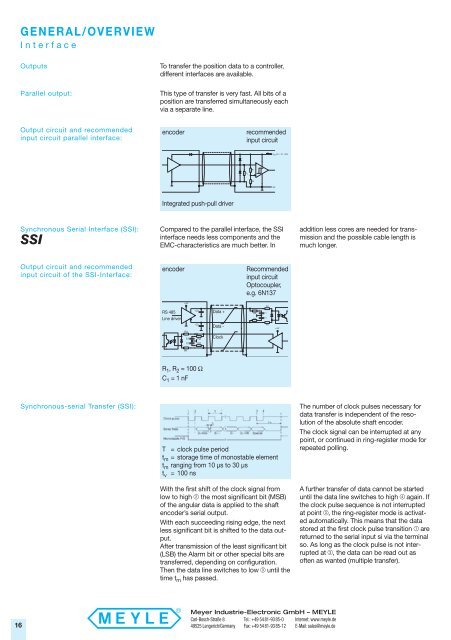
Outputs To transfer the position data to a controller,<br />
different interfaces are available.<br />
Parallel output: This type of transfer is very fast. All bits of a<br />
position are transferred simultaneously each<br />
via a separate line.<br />
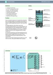
Output circuit and recommended<br />
input circuit parallel interface:<br />
Synchronous Serial Interface (SSI): Compared to the parallel interface, the SSI<br />
interface needs less components and the<br />
SSI<br />
EMC-characteristics are much better. In<br />
Output circuit and recommended<br />
input circuit of the SSI-Interface:<br />
Synchronous-serial Transfer (SSI):<br />
encoder recommended<br />
input circuit<br />
Integrated push-pull driver<br />
encoder Recommended<br />
input circuit<br />
Optocoupler,<br />
e.g. 6N137<br />
RS 485<br />
Line driver<br />
R 1 , R 2 = 100 Ω<br />
C 1 = 1 nF<br />
Data +<br />
Data -<br />
Clock<br />
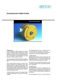
T = clock pulse period<br />
t m = storage time of monostable element<br />
t m ranging from 10 µs to 30 µs<br />
t v = 100 ns<br />
With the first shift of the clock signal from<br />
low to high " the most significant bit (MSB)<br />
of the angular data is applied to the shaft<br />
encoder’s serial output.<br />
With each succeeding rising edge, the next<br />
less significant bit is shifted to the data output.<br />
After transmission of the least significant bit<br />
(LSB) the Alarm bit or other special bits are<br />
transferred, depending on configuration.<br />
Then the data line switches to low § until the<br />
time t m has passed.<br />
Meyer <strong>Industrie</strong>-<strong>Electronic</strong> GmbH – MEYLE<br />
Carl-Bosch-Straße 8<br />
49525 Lengerich/Germany<br />
Tel.: +49 54 81-93 85-0<br />
Fax: +49 54 81-93 85-12<br />
addition less cores are needed for trans -<br />
mission and the possible cable length is<br />
much longer.<br />
The number of clock pulses necessary for<br />
data transfer is independent of the resolution<br />
of the absolute shaft encoder.<br />
The clock signal can be interrupted at any<br />
point, or continued in ring-register mode for<br />
repeated polling.<br />
A further transfer of data cannot be started<br />
until the data line switches to high $ again. If<br />
the clock pulse sequence is not interrupted<br />
at point §, the ring-register mode is activated<br />
automatically. This means that the data<br />
stored at the first clock pulse transition ! are<br />
returned to the serial input si via the terminal<br />
so. As long as the clock pulse is not interrupted<br />
at §, the data can be read out as<br />
often as wanted (multiple transfer).<br />
Internet: www.meyle.de<br />
E-Mail: sales@meyle.de