user manual rasmus 1 radar signal multiplying ... - Polaris-as.dk
user manual rasmus 1 radar signal multiplying ... - Polaris-as.dk
user manual rasmus 1 radar signal multiplying ... - Polaris-as.dk

You also want an ePaper? Increase the reach of your titles
YUMPU automatically turns print PDFs into web optimized ePapers that Google loves.
USER MANUAL<br />
RASMUS 1<br />
RADAR SIGNAL MULTIPLYING SYSTEM<br />
RTE RADAR TARGET ENHANCER
p. 1
Contents<br />
Introduction...……………………………………………….3<br />
Safety Precautions………………………………….……..3<br />
Instrument Description..…………………………………..3<br />
Certification..……………………………………………….4<br />
Delivery Set.……..………………………………………...4<br />
Control Unit Functions……………………………………5<br />
Control Unit..………………………………………………5<br />
Setting into Operation…………………………………….6<br />
Technical Data.……………………………………………7<br />
Warranty...…………………………………………………7<br />
Declaration of Conformity.....…………………………….8<br />
Drilling Templates.………..………………………………9<br />
Notes..….…………………………………………………11<br />
Address..….………………………………………………12<br />
p. 2
Introduction<br />
We highly appreciate your confidence in and choice of the Dantronik-Marine <strong>r<strong>as</strong>mus</strong><br />
GmbH product. This User Manual provides essential information related to function,<br />
installation, mounting, servicing, and troubleshooting of your <strong>r<strong>as</strong>mus</strong> 1. Therefore, prior<br />
to use of the instrument, read this Manual thoroughly and then follow it accurately.<br />
<strong>r<strong>as</strong>mus</strong> 1 is designed to resist all and operate reliably in extreme weather conditions.<br />
Safety Precautions<br />
Use the instrument for the intended purpose only, note supply voltage data, and<br />
connect the instrument to an authorized voltage supply only. This is the way to ensure<br />
the reliable and safe operation. Any different way to use the instrument may cause unit<br />
damage and risks during use.<br />
• <strong>r<strong>as</strong>mus</strong> 1 h<strong>as</strong> no wearing parts. So never open the instrument and never<br />
try to repair it by yourself.<br />
• This instrument is designed to incre<strong>as</strong>e your safety. So handle it carefully.<br />
If suspecting that the instrument may be not used further for the intended<br />
purpose, switch it out off and send it back to Dantronik-Marine <strong>r<strong>as</strong>mus</strong><br />
GmbH for inspection.<br />
• On activation, <strong>r<strong>as</strong>mus</strong> 1 sends out <strong>radar</strong> frequencies. Avoid direct<br />
exposure to this. So keep yourself at a safe distance of at le<strong>as</strong>t 0.5 m<br />
apart!<br />
• This is a safety relevant device, which runs a self-test after power on. You<br />
should initiate it on regular b<strong>as</strong>is. (See the self-test description in<br />
paragraph “Setting into Operation”).<br />
Instrument Description<br />
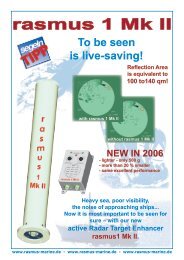
<strong>r<strong>as</strong>mus</strong> 1 is an active, electronic Radar Reflector, an active Radar Target Enhancer,<br />
designed to improve the navigation safety. On receiving a <strong>radar</strong> <strong>signal</strong> when in standby<br />
mode, the instrument is activated automatically and sends back an electronically<br />
amplified echo to the <strong>radar</strong> display screen of the transmitter. On heavy-traffic seaways<br />
and mainly during the dark time and in bad weather conditions such <strong>as</strong> fog, storm, and<br />
heavy rain, <strong>r<strong>as</strong>mus</strong> 1 allows small boats (motorboats, yachts, and rubber boats) to be<br />
reliably detected by ships’ <strong>radar</strong> screens.<br />
Additionally an audio <strong>signal</strong> is integrated to indicate a <strong>radar</strong> <strong>signal</strong> is received – when<br />
switched on- by buzzing sound. This is in particular <strong>as</strong> well recommended for<br />
yachtsmen going on one hand tour <strong>as</strong> for sailing with small crews!<br />
Note: The supply voltage should be within the range of 12 to 24 VDC to ensure<br />
compliance with all specified characteristics and essential technical requirements.<br />
p. 3
Certification<br />
The instrument is EC Directive R&TTE certified and h<strong>as</strong> been tested to:<br />
EN 60215, EN 60945, EN ETS 301 843-1, and intern. recommendation ITU-R M.1176<br />
with reference to: Reg TP SSB OR-N006<br />
Tested and approved by BSH (Federal Naval Hydrographic Office, Germany)<br />
СE 0560 !<br />
According to the EC Directive, this product is approved for use in the following<br />
countries:<br />
•approved for unrestricted use<br />
Х – not applied for Notification<br />
Y – <strong>user</strong>’s application for national permit to use is mandatory<br />
Countries:<br />
В – Belgium •<br />
IRL – Ireland Y<br />
P – Portugal •<br />
D – Germany •<br />
I – Italy •<br />
IS – Iceland •<br />
CH – Switzerland X<br />
E – Spain Y<br />
L – Luxemburg X<br />
S – Sweden •<br />
FIN – Finland Y<br />
GR – Greece •<br />
NL – the Netherlands •<br />
UK- United Kingdom •<br />
F – France •<br />
A – Austria X<br />
Delivery Set<br />
Instrument includes:<br />
1. Antenna Unit<br />
2. Control Unit<br />
3. Cable (15-m and 10-m long sections between the control unit and antenna,<br />
respectively, the control unit and battery).<br />
4. Battery Connector Terminals<br />
p. 4
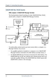
Description of the picture<br />
Indication: Power On: Standby Indication: Buzzer On<br />
On/Off Switch Indication: Radar Contact Activated<br />
Buzzer Switch On/Off<br />
Fuse Cable connecting to the onboard battery<br />
Wiring diagram Cable connecting from the Antenna to the<br />
Control Unit<br />
Function of the Control Unit<br />
Switch “POWER”<br />
By pressing the switch button, power is on. <strong>r<strong>as</strong>mus</strong> 1 is now in the standby mode.<br />
Green indicator “POWER” – the LH light-emitting diode (LED) – starts blinking. By<br />
pressing again, power is off.<br />
Red LED “RADAR”<br />
This LED blinks if <strong>r<strong>as</strong>mus</strong> 1 is hit by a <strong>radar</strong> beam.<br />
Switch “BUZZER»<br />
This switch allows audio <strong>signal</strong> activation. Additionally, RH LED blinks green if<br />
“BUZZER” is activated. In c<strong>as</strong>e of <strong>radar</strong> contact, the buzzing sound is active.<br />
Installation<br />
Installation needs to be done by trained personnel, with following strictly installation<br />
instructions!<br />
Antenna Unit (1)<br />
The antenna unit shall be mounted when at a fixed moorage or winter stay. It may be<br />
fixed with 8 screws or wood screws to any suitable or special <strong>r<strong>as</strong>mus</strong> 1 attachment<br />
(rigging), e.g. on the m<strong>as</strong>t top, in aft b<strong>as</strong>ket, or on a flat surface (the cabin roof).<br />
Observe the rule: the higher the mounting point, the larger the effective range. So avoid<br />
mounting below the height of 2 m above water level! Further, if possible: Ple<strong>as</strong>e avoid<br />
<strong>as</strong> far <strong>as</strong> possible that Antenna is shaded by materials or superstructures.<br />
When mounting the antenna, be careful to prevent contact corrosion damages in<br />
between the instrument and a bearing surface. So we recommend applying a packing<br />
rubber collar (rigging). Be careful also to keep the distance of at le<strong>as</strong>t 1 m from metallic<br />
items for perfect operation. Lay the cable from the control unit to the antenna so that it is<br />
clear of and resistant to wear factors to ensure damage protection. To ensure the<br />
instrument to operate perfectly, never shorten or extend the cable. If trimming is<br />
required, ple<strong>as</strong>e contact the manufacturer so <strong>as</strong> to avoid loss of warranted benefits.<br />
p. 5
Control Unit (2)<br />
The onboard mains must be voltage free when connecting to it during installation! It is<br />
advisable to place the control unit in the cabin (wheel house) or near the boat rudder. If<br />
possible, it is necessary to protect it against water spl<strong>as</strong>hes, and to fix it with four<br />
screws or wood screws. The control unit should be installed in a (closed) cabin,<br />
wheelhouse, or near a control board. The power cable should be connected to an<br />
onboard battery or mains having a nominal voltage of 12 to 24 VDC. Ple<strong>as</strong>e, observe<br />
the voltage polarity! Caution: the short circuit causes the risk of damage to the onboard<br />
battery. Take care that the battery is in a good charged state.<br />
Setting into Operation<br />
After mechanical and electrical installation, the functional tests shall be run. Firstly,<br />
energize the system by pressing switch “POWER“. Blinking of green LED indicates that<br />
power is on.<br />
Test 1 (without <strong>radar</strong> contact)<br />
Simultaneously with the green LED, the Red LED “RADAR” blinks for a second to<br />
indicate that the instrument operates properly. This is self-testing of your <strong>r<strong>as</strong>mus</strong> 1,<br />
running each time, the system is started.<br />
The instrument is now in the standby mode.<br />
Functional test (with <strong>radar</strong> contact)<br />
After successful self-testing, red LED blinks to indicate when the instrument h<strong>as</strong> <strong>radar</strong><br />
contact. In these c<strong>as</strong>es the instrument is active. If “BUZZER” is activated by switch<br />
pressing, the buzzing sound is active and the <strong>as</strong>sociated green LED blinks.<br />
In c<strong>as</strong>e of malfunctioning, ple<strong>as</strong>e check all plug-in connections, wiring, and polarity. If<br />
everything is connected properly, the battery power must be checked. If the battery is<br />
well-charged check the fuse of the control unit - and, if required, replace it (5 × 20 mm<br />
low-current fuse, 1А, of central slow type).<br />
p. 6
Technical Data<br />
Consumption current in p<strong>as</strong>sive mode ≤70 mA<br />
in active mode ≤380 mA<br />
Supply voltage 12-24 VDC<br />
Frequency 9.3-9.5 GHz<br />
Effective range 0.1-12 nm (depending on the height and place of installation)<br />
Gain 58 dB typ.<br />
Coverage in azimuth 360°<br />
in elevation ±12.5°<br />
Output pulse power 0.8 W typ. (E.I.R.P. output)<br />
0.6 W min.<br />
Receiver sensitivity better than –48 dBm (E.I.R.P.input)<br />
Operating temperature –30 to +60 °C<br />
Storage temperature –50 to +65 °C<br />
Antenna length 480 mm<br />
Diameter (without mounting plate) 78 mm<br />
Mounting plate diameter 80 mm<br />
Antenna weight 1.3 kg<br />
Antenna waterproof accord. IP 68<br />
Control unit: dimensions 68×115×49 mm<br />
Control unit waterproof accord. IP 66<br />
Control unit weight 0.3 kg<br />
(We reserve the right to alterations)<br />
Warranty<br />
Within the scope of the manufacturer’s terms and limited to this, we warrant the proper<br />
operation of the instrument, provided that all the instructions of this Manual are fully<br />
met, the instrument is not mechanically damaged, and no evidence of opening and<br />
repair is found. The warranty period is 3 years from the date of sale/date of invoice. We<br />
warrant that the improperly operating instrument will be subject to a selective repair or<br />
replaced by a new one. Our liability is limited to the purch<strong>as</strong>e value of our device. All<br />
further going damages and claims are excluded.<br />
The instrument must be sent directly at our address, with the attached invoice copy and<br />
brief defect description.<br />
We return the instrument also directly at the customer’s address.<br />
p. 7
Declaration of Conformity<br />
Declaration of Conformity<br />
I hereby declare that the product<br />
Dantronik-Marine, <strong>r<strong>as</strong>mus</strong>1<br />
(name of product, type or model, batch or serial number)<br />
is conformity with the essential requirements <strong>as</strong> described in Directive<br />
1999/5/EC<br />
and satisfies all the technical regulations applicable to the product within this directive<br />
Recommendation ITU-R.M. 1176 (reg. TP SSB OR-006)<br />
RN ETS 301 843-1<br />
IEC 945/EN60945<br />
IEC 215/EN60215<br />
Title(s) of regulations, standards, etc.<br />
MANUFACTURER:<br />
Address:<br />
Dantronik-Marine <strong>r<strong>as</strong>mus</strong> GmbH<br />
Fahrensodde 20<br />
D-24944 Flensburg<br />
GERMANY<br />
- Point of contact:<br />
E. Wabbel, +49 461 31 33 -109, fax ext. 200 ew@dantronik-marine.de<br />
(Name, telephone, fax number and e-mail)<br />
Flensburg, den 22. May 2003<br />
Dantronik-Marine <strong>r<strong>as</strong>mus</strong> GmbH<br />
p. 8
DRILLING TEMPLATES<br />
Antenna unit<br />
Figure<br />
p. 9
DRILLING TEMPLATES<br />
Control Unit<br />
Figure<br />
p. 10
Notes<br />
p. 11
Address:<br />
Marine <strong>r<strong>as</strong>mus</strong> GmbH<br />
Fahrensodde 20<br />
D-24944 Flensburg<br />
Germany<br />
Telephone: +49 461 31 33 0<br />
Fax: +49 461 31 13 200<br />
Rev.: May 2003<br />
www.dantronik-marine.de<br />
e-mail: info@dantronik-marine.de<br />
p. 12