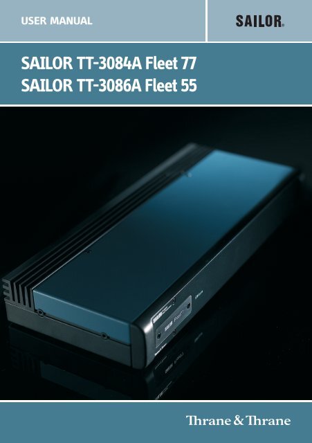
SAILOR TT-3084A Fleet 77 SAILOR TT-3086A Fleet 55 - Polaris-as.dk
SAILOR TT-3084A Fleet 77 SAILOR TT-3086A Fleet 55 - Polaris-as.dk
SAILOR TT-3084A Fleet 77 SAILOR TT-3086A Fleet 55 - Polaris-as.dk

You also want an ePaper? Increase the reach of your titles
YUMPU automatically turns print PDFs into web optimized ePapers that Google loves.
USER MANUAL<br />
<strong>SAILOR</strong> <strong>TT</strong>-<strong>3084A</strong> <strong>Fleet</strong> <strong>77</strong><br />
<strong>SAILOR</strong> <strong>TT</strong>-<strong>3086A</strong> <strong>Fleet</strong> <strong>55</strong>
Thrane & Thrane A/S<br />
<strong>SAILOR</strong> <strong>Fleet</strong><strong>77</strong> <strong>TT</strong>-<strong>3084A</strong><br />
<strong>SAILOR</strong> <strong>Fleet</strong><strong>55</strong> <strong>TT</strong>-<strong>3086A</strong><br />
User Manual<br />
Document number: <strong>TT</strong>98-116874-I<br />
Rele<strong>as</strong>e date: August 26, 2008
Disclaimer<br />
Any responsibility or liability for loss or damage in connection with the use of this<br />
product and the accompanying documentation is disclaimed by Thrane & Thrane. The<br />
information in this manual is provided for information purposes only, is subject to<br />
change without notice, may contain errors or inaccuracies, and represents no<br />
commitment whatsoever by Thrane & Thrane. This agreement is governed by the laws of<br />
Denmark.<br />
Manuals issued by Thrane & Thrane are periodically revised and updated. Anyone<br />
relying on this information should satisfy himself/herself <strong>as</strong> to the most current version.<br />
Providers with access to Thrane & Thrane’s Extranet may obtain current copies of<br />
manuals at: http://extranet.thrane.com.<br />
Thrane & Thrane is not responsible for the content or accuracy of any translations or<br />
reproductions, in whole or in part, of this manual from any other source.<br />
Copyright<br />
© 2008 Thrane & Thrane A/S. All rights reserved. Printed in Denmark.<br />
Trademark Acknowledgements<br />
• Inmarsat is a registered trademark of the International Maritime Satellite<br />
Organisation (IMSO) and is licensed by IMSO to Inmarsat Limited and Inmarsat<br />
Ventures plc.<br />
• Inmarsat’s product names are either trademarks or registered trademarks of<br />
Inmarsat.<br />
• WinPoET is a trademark of iV<strong>as</strong>ion, a RouterWare Company.<br />
• Other product and company names mentioned in this manual may be trademarks or<br />
trade names of their respective owners.
Safety Summary 1<br />
The following general safety precautions must be observed during all<br />
ph<strong>as</strong>es of operation, service and repair of this equipment. Failure to comply<br />
with these precautions or with specific warnings elsewhere in this manual<br />
violates safety standards of design, manufacture and intended use of the<br />
equipment. Thrane & Thrane A/S <strong>as</strong>sume no liability for the customer's<br />
failure to comply with these requirements.<br />
Microwave Radiation Hazards<br />
During transmission the antenna in this system radiates Microwave Power.<br />
This radiation may be hazardous if exposed directly to humans, close to the<br />
antenna. During transmission, make sure that nobody gets closer than the<br />
recommended minimum safety distance. The minimum safety distance to the<br />
antenna on the focal line, is 3.6m.<br />
MICROWAVE<br />
NO PERSONNEL<br />
b<strong>as</strong>ed on 10W/m2<br />
25°<br />
2 m (F<strong>55</strong>)<br />
3.6 m (F<strong>77</strong>)<br />
GROUND THE EQUIPMENT<br />
To minimize shock hazard, the equipment ch<strong>as</strong>sis and cabinet must be<br />
connected to an electrical ground.<br />
iii
iv<br />
DO NOT OPERATE IN AN EXPLOSIVE ATMOSPHERE<br />
Do not operate the equipment in the presence of flammable g<strong>as</strong>es or fumes.<br />
Operation of any electrical equipment in such an environment constitutes a<br />
definite safety hazard.<br />
KEEP AWAY FROM LIVE CIRCUITS<br />
Operating personnel must not remove equipment covers. Component<br />
replacement and internal adjustment must be made by qualified<br />
maintenance personnel. Do not replace components with the power cable<br />
connected. Under certain conditions, dangerous voltages may exist even<br />
with the power cable removed. To avoid injuries, always disconnect power<br />
and discharge circuits before touching them.<br />
DO NOT SERVICE OR ADJUST ALONE<br />
Do not attempt internal service or adjustments unless another person,<br />
capable of rendering first aid resuscitation, is present.
Chapter 1 About the Manual<br />
Table of Contents<br />
Chapter 2 Introduction<br />
The Inmarsat <strong>Fleet</strong> Service ..................................................3<br />
The <strong>SAILOR</strong> <strong>Fleet</strong><strong>77</strong> system..................................................7<br />
The <strong>SAILOR</strong> <strong>Fleet</strong><strong>55</strong> system ............................................... 10<br />
Hardware Interfaces...........................................................13<br />
The Handset......................................................................22<br />
Distress Cradle ..................................................................33<br />
Chapter 3 Getting started<br />
Getting ready to make a call..............................................35<br />
Use of PIN codes. ..............................................................39<br />
Normal calls.......................................................................41<br />
Distress call.......................................................................43<br />
MPDS connection..............................................................45<br />
ISDN Connection ............................................................... 47<br />
Chapter 4 Operation<br />
Menu System ....................................................................49<br />
Call functions ....................................................................60<br />
Super User functions.........................................................64<br />
Chapter 5 PC programs<br />
System set-up using <strong>Fleet</strong>CP .............................................95<br />
v
Table of Contents<br />
vi<br />
Setting up data equipment .............................................. 105<br />
Setup using Ethernet/PPPoE............................................ 129<br />
Chapter 6 Troubleshooting<br />
Appendix A Menu Tree<br />
List of Error messages...................................................... 135<br />
Glossary ....................................................................................... 165<br />
Index ....................................................................................... 169
Chapter 1<br />
About the Manual 1<br />
Congratulations on purch<strong>as</strong>ing your <strong>SAILOR</strong> <strong>Fleet</strong> product.<br />
Whether you have chosen a <strong>TT</strong>-<strong>3084A</strong> <strong>SAILOR</strong> <strong>Fleet</strong><strong>77</strong> or a <strong>TT</strong>-<strong>3086A</strong> <strong>SAILOR</strong><br />
<strong>Fleet</strong><strong>55</strong>, the system makes it possible for you to communicate from virtually<br />
any ocean region in the world using the Inmarsat <strong>Fleet</strong> service established by<br />
Inmarsat.<br />
Both systems support high-speed data (64 kbit/s circuit switched and packet<br />
data) and high quality voice <strong>as</strong> well <strong>as</strong> inexpensive voice services. In addition<br />
the <strong>SAILOR</strong> <strong>Fleet</strong><strong>77</strong> optionally supports 128 kbit/s data service.<br />
This manual h<strong>as</strong> the following chapters:<br />
• Introduction - an overview of the Inmarsat <strong>Fleet</strong> system and its services.<br />
• Getting started - a description of how to make and receive calls and the use<br />
of PIN codes.<br />
• Operation - a detailed description of the menu system in the BDU.<br />
• PC programs - a description of how to use the accompanying configuration<br />
PC software (<strong>Fleet</strong>CP) and to setup the PC for data connections.<br />
• Troubleshooting – a description of the most common errors, how to deal<br />
with them and how to get further help if necessary.<br />
Additionally you will find a glossary of abbreviations and an index at the end<br />
of the manual.<br />
1
Chapter 1: About the Manual<br />
2
Chapter 2<br />
Introduction 2<br />
The Inmarsat <strong>Fleet</strong> Service 2.1<br />
Overview 2.1.1<br />
The Inmarsat <strong>Fleet</strong> service is b<strong>as</strong>ed on 4 Geostationary 3rd generation<br />
satellites situated above the equator, but can also operate on the new 4th<br />
generation satellites. Geostationary means that the satellites are always<br />
located in the same position, i.e. they rotate at the same speed <strong>as</strong> that of the<br />
earth. Each satellite covers a certain area (footprint) and supports a number of<br />
powerful spot-beams making the service available in virtually all ocean<br />
regions on the earth between approximately 70°N and 70°S.<br />
The 4 Geostationary Inmarsat Satellites<br />
The satellites are your connection to the worldwide networks, and they are<br />
managed by the Network Coordination Stations (NCSs), run by Inmarsat. The<br />
primary functions of the NCSs are to constantly keep track of which terminals<br />
are logged on to the system, and <strong>as</strong>sign a free channel whenever a call is<br />
made.<br />
The gateway between the public network and the satellites is operated by<br />
Land Earth Stations (LES). The LESs are run by different operators around the<br />
world.<br />
3
Chapter 2: Introduction<br />
Services 2.1.2<br />
The Inmarsat <strong>Fleet</strong> service supports the following services:<br />
• High speed services<br />
• 2 x 64 / 2 x 56 kbit/s data 1<br />
• 64 kbit/s data<br />
• 56 kbit/s data<br />
• Speech<br />
• 3.1 kHz audio<br />
• MPDS<br />
• Low speed services<br />
• Mini-M voice<br />
• 9.6 kbit fax<br />
For a detailed description of each service see the l<strong>as</strong>t section of this chapter.<br />
1. 128 kbit/s is only available on new F<strong>77</strong> systems<br />
4 The Inmarsat <strong>Fleet</strong> Service
2222<br />
Chapter 2: Introduction<br />
The available services allow for a wide range of applications. Examples are<br />
shown below.<br />
Important Before a terminal can be used on the network, it h<strong>as</strong> to be<br />
commissioned by one of the Inmarsat Service Providers (ISPs).<br />
In order to use the different Inmarsat <strong>Fleet</strong> services it is<br />
necessary to have at le<strong>as</strong>t one Inmarsat Mobile Number (IMN)<br />
for each of the above mentioned services. In c<strong>as</strong>e all 8 services<br />
are commissioned on your terminal, you will have 8 IMN<br />
numbers.<br />
Calling an Inmarsat <strong>Fleet</strong> terminal corresponds to making international calls.<br />
If the satellite region/area is not known for the terminal the “country” code for<br />
a terminal is 870. When you dial up to an Inmarsat <strong>Fleet</strong> terminal through the<br />
public network, you have to dial the IMN number in addition to the<br />
international access code for Inmarsat, e.g.:<br />
+870 600 <strong>55</strong>5 <strong>55</strong>5<br />
Making calls from an Inmarsat <strong>Fleet</strong> terminal corresponds to making<br />
international calls, meaning you must always dial the country code.<br />
The Inmarsat <strong>Fleet</strong> Service 5<br />
Introduction
Chapter 2: Introduction<br />
Service explanation 2.1.3<br />
The low speed services have a lower tariff than the high speed services,<br />
because the high speed services are high quality audio or high speed data<br />
services that require more bandwidth.<br />
• The 128 kbit/s UDI (Unrestricted Digital Information) service enables 2 x 64<br />
kbit/s or 2 x 56 kbit/s bidirectional transmission of data to and from<br />
terrestrial ISDN networks<br />
• The 64 kbit/s UDI (Unrestricted Digital Information) service enables the<br />
bidirectional transmission of data to and from terrestrial 64 kbit/s ISDN<br />
networks. The 56 kbit/s UDI service is similarly used to make a connection<br />
to 56 kbit/s ISDN networks, which are primarily used in North America.<br />
• The Speech and 3.1 kHz audio services make it possible to establish high<br />
quality analogue connections of a quality equal to terrestrial analogue<br />
connections via digital networks/switches. The Speech service is used for<br />
high quality voice connections, where<strong>as</strong> 3.1 kHz audio can be used to<br />
transfer analogue signals between fax machines and modems with an<br />
analogue 2-wire interface. The 3.1 kHz audio service is transparent, and is<br />
suitable for all analogue applications including secure telephones.<br />
• The MPDS service is a packet data service where the tariff depends on the<br />
amount of data sent and received. This service is a more cost-effective<br />
solution for web browsing, and other applications where there is no need<br />
for constant transmission of data in both directions. It is also suitable for<br />
applications where a constant connection is required, because the user is<br />
no longer charged the “per minute rate”.<br />
• The Mini-M voice service is only for voice transmission. The voice<br />
transmitted over the satellite is subject to a compression process that<br />
reduces the bandwidth to 4.8 kbit/s and consequently reduces the cost.<br />
• The 9.6 kbit Fax allows you to send and receive fax messages using a<br />
standard office fax machine. This service replaces the previous Mini-M fax<br />
service. Using this service is usually more cost effective compared to the<br />
3.1 kHz audio service.<br />
6 The Inmarsat <strong>Fleet</strong> Service
2222<br />
Chapter 2: Introduction<br />
The <strong>SAILOR</strong> <strong>Fleet</strong><strong>77</strong> system 2.2<br />
Overview 2.2.1<br />
The <strong>SAILOR</strong> <strong>Fleet</strong><strong>77</strong> System includes the following system components:<br />
• <strong>TT</strong>-3008C <strong>SAILOR</strong> <strong>Fleet</strong><strong>77</strong> Antenna (ADU)<br />
• <strong>TT</strong>-3038C <strong>SAILOR</strong> <strong>Fleet</strong><strong>77</strong> Electronics Unit (BDU)<br />
• <strong>TT</strong>-3622B <strong>SAILOR</strong> <strong>Fleet</strong><strong>77</strong> Distress Cradle<br />
• <strong>TT</strong>-3620F <strong>SAILOR</strong> <strong>Fleet</strong> Control Handset (4 wire)<br />
• Accessories (manual, software, etc.)<br />
For instructions on how to <strong>as</strong>semble the system, wiring and specifications, see<br />
the Installation Manual.<br />
The <strong>SAILOR</strong> <strong>Fleet</strong><strong>77</strong> system 7<br />
Introduction
Chapter 2: Introduction<br />
<strong>TT</strong>-3008C Antenna 2.2.2<br />
The <strong>TT</strong>-3008C antenna or ADU (Above Deck Unit) is a stabilized high-gain<br />
antenna. The antenna contains all functions for satellite tracking including a<br />
GPS system.<br />
<strong>TT</strong>-3038C-128 <strong>SAILOR</strong> <strong>Fleet</strong><strong>77</strong> Electronics Unit (BDU) 2.2.3<br />
All connectors for external equipment are placed on the rear of the BDU<br />
(Below Deck Unit). On the front a configuration module is attached. This<br />
module stores all system configuration data. It contains all necessary data to<br />
recover the system after a replacement of the BDU.<br />
8 The <strong>SAILOR</strong> <strong>Fleet</strong><strong>77</strong> system
2222<br />
Chapter 2: Introduction<br />
<strong>TT</strong>-3622B <strong>SAILOR</strong> <strong>Fleet</strong> Cradle with Distress and<br />
<strong>TT</strong>-3620F <strong>SAILOR</strong> <strong>Fleet</strong> Control Handset (4 wire) 2.2.4<br />
The handset is primary used to make telephone calls. Furthermore it can be<br />
used to configure the system. For a detailed description of the handset see the<br />
section The Handset on page 22.<br />
The cradle h<strong>as</strong> a distress button, a stop button and three LEDs. The distress<br />
button, which is protected by pl<strong>as</strong>tic gl<strong>as</strong>s, is used to initiate a distress call.<br />
The stop button can be used to abort a distress call. The three LEDs indicate<br />
power, distress test and priority calls. For a detailed description of the cradle<br />
see the section Distress Cradle on page 33.<br />
The <strong>SAILOR</strong> <strong>Fleet</strong><strong>77</strong> system 9<br />
Introduction
Chapter 2: Introduction<br />
The <strong>SAILOR</strong> <strong>Fleet</strong><strong>55</strong> system 2.3<br />
Overview 2.3.1<br />
The <strong>SAILOR</strong> <strong>Fleet</strong><strong>55</strong> System includes the following system components:<br />
• <strong>TT</strong>-3008F <strong>SAILOR</strong> <strong>Fleet</strong><strong>55</strong> Antenna (ADU)<br />
• <strong>TT</strong>-3038C-WMx <strong>SAILOR</strong> <strong>Fleet</strong><strong>55</strong> Electronics Unit (BDU)<br />
• <strong>TT</strong>-3622C <strong>SAILOR</strong> <strong>Fleet</strong> Cradle without Distress<br />
• <strong>TT</strong>-3620F <strong>SAILOR</strong> <strong>Fleet</strong> Control Handset (4 wire)<br />
• Accessories (manual, software, etc.)<br />
For instructions on how to <strong>as</strong>semble the system, wiring and specifications, see<br />
the Installation Manual.<br />
10 The <strong>SAILOR</strong> <strong>Fleet</strong><strong>55</strong> system
2222<br />
Chapter 2: Introduction<br />
<strong>TT</strong>-3008F <strong>SAILOR</strong> <strong>Fleet</strong><strong>55</strong> Antenna 2.3.2<br />
The <strong>TT</strong>-3008F antenna or ADU (Above Deck Unit) is a stabilized high-gain<br />
antenna. The antenna contains all functions for satellite tracking including a<br />
GPS system.<br />
<strong>TT</strong>-3038C-WMx <strong>SAILOR</strong> <strong>Fleet</strong><strong>55</strong>/<strong>77</strong> Electronics Unit (BDU) 2.3.3<br />
All connectors for external equipment are placed on the rear of the BDU. On<br />
the front a configuration module is attached. This module stores all system<br />
configuration data. It contains all necessary data to recover the system after a<br />
replacement of the BDU.<br />
The <strong>SAILOR</strong> <strong>Fleet</strong><strong>55</strong> system 11<br />
Introduction
Chapter 2: Introduction<br />
<strong>TT</strong>-3622C <strong>SAILOR</strong> <strong>Fleet</strong> Cradle without Distress and<br />
<strong>TT</strong>-3620F <strong>SAILOR</strong> <strong>Fleet</strong> Control Handset (4 wire) 2.3.4<br />
The handset is primarily used to make telephone calls. Furthermore it can be<br />
used to configure the system. For a detailed description of the handset see<br />
section The Handset on page 22.<br />
12 The <strong>SAILOR</strong> <strong>Fleet</strong><strong>55</strong> system
2222<br />
Chapter 2: Introduction<br />
Hardware Interfaces 2.4<br />
Overview 2.4.1<br />
The Electronic Units of the <strong>SAILOR</strong> <strong>Fleet</strong><strong>77</strong> and the <strong>SAILOR</strong> <strong>Fleet</strong><strong>55</strong> have the<br />
following hardware interfaces:<br />
• Analogue RJ11 number 1 (X1)<br />
• Analogue RJ11 number 2 (X2)<br />
• Analogue RJ11 number 3 (X3)<br />
• Handset 1 (X4)<br />
• Handset 2 (X5) (For future use)<br />
• ISDN (Integrated Services Digital Network) (X7)<br />
• USB (Universal Serial Bus) (X8)<br />
• Ethernet (X9)<br />
• Serial connector 1 (X10)<br />
• NMEA 0183 (X11)<br />
• 4 Discrete I/O (X12)<br />
• Power Connector (X13)<br />
All connectors for these interfaces are found on the rear of the Electronic Unit:<br />
X1 X2 X3 X4 X5 X6 X7 X8 X9 X10 X11 X12 X13<br />
These interfaces can be used for the different Inmarsat <strong>Fleet</strong> services.<br />
Hardware Interfaces 13<br />
Introduction
Chapter 2: Introduction<br />
Two Cradle/Handset interfaces 2.4.2<br />
The BDU h<strong>as</strong> two 4 wire handset ports with RS-485 data control.<br />
Each handset can be used to set up the terminal and it can be used to make or<br />
receive phone calls using one of the following services:<br />
• Speech<br />
• 3.1 kHz audio<br />
• Mini-M voice<br />
• Distress call<br />
Cradle/Handset<br />
14 Hardware Interfaces
2222<br />
Chapter 2: Introduction<br />
Three Analogue RJ11 interfaces 2.4.3<br />
RJ11<br />
The RJ11 ports shown above can be used for connection of analogue phones.<br />
For all interfaces the following services can be used:<br />
• Speech<br />
• 3.1 kHz audio<br />
• Mini-M voice<br />
• 9.6 kbit/s fax<br />
The type of service used on each interface is independent of each other and<br />
can be configured in the Routing menu.<br />
Hardware Interfaces 15<br />
Introduction
Chapter 2: Introduction<br />
ISDN interface 2.4.4<br />
This interface can be used for connection of ISDN equipment – data <strong>as</strong> well <strong>as</strong><br />
voice/picture b<strong>as</strong>ed equipment (phones, modems, terminal adapters, audio<br />
codecs, video conferencing equipment, STE secure voice, etc.).<br />
On F<strong>55</strong> only one B-channel (1 x 64 kbit/s Data) and one D-channel (control) is<br />
used.<br />
The F<strong>77</strong> optionally supports two B-channels (2 x 64 kbit/s Data). In order to<br />
enable this service you need to enter a special PIN code. Ple<strong>as</strong>e contact your<br />
supplier to retrieve a pin code. As with other services the terminal needs to be<br />
commissioned to this service (see the section The Inmarsat <strong>Fleet</strong> Service on<br />
page 3).<br />
The terminal does not support dynamic switching between one and two Bchannels.<br />
The user needs to decide to use one or two channels before<br />
establishing the call.<br />
When using only one B-channel, ple<strong>as</strong>e ensure that your ISDN equipment is<br />
configured to support one B-channel only.<br />
The following services may be used on the ISDN interface:<br />
• 128 kbit/s UDI (option on F<strong>77</strong>)<br />
• 64 kbit/s UDI<br />
• 56 kbit/s UDI<br />
• Speech<br />
• 3.1 kHz audio<br />
ISDN<br />
• Mini-M voice<br />
Like the terrestrial ISDN network the terminal offers the possibility to have<br />
more than one device connected to this interface. Each device can be<br />
16 Hardware Interfaces
2222<br />
Chapter 2: Introduction<br />
individually addressed when called, and the service type can be selected<br />
individually. This requires that the attached equipment supports MSN<br />
(Multiple Subscriber Number). Depending on the brand of equipment it may<br />
be possible to program the equipment with more MSNs. If a device should<br />
respond to a certain IMN number, it must be programmed in the ISDN<br />
equipment using the IMN <strong>as</strong> MSN. Note that the equipment will only react if<br />
both MSN and service type (speech, 3.1 kHz audio, 128 kbit/s, 64 kbit/s or 56<br />
kbit/s) fit the ISDN equipment.<br />
Note When the 128 kbit/s service is not used, the ISDN interface supports<br />
data transmission of one B-channel at 64 or 56 kbit/s <strong>as</strong> opposed to<br />
two B-channels at 64 or 56 kbit/s available on the terrestrial ISDN<br />
network.<br />
When using satellite equipment a delay is introduced due to the satellite link.<br />
Not all standard ISDN devices are equally good at coping with this.<br />
RS-232 interface 2.4.5<br />
The RS-232 interface is a standard 9-pin serial ports, with a maximum port<br />
speed of 115.2 kbit/s. The interface supports the following service types:<br />
• MPDS service<br />
• Configuration of the terminal via <strong>Fleet</strong>CP software (See the section System<br />
set-up using <strong>Fleet</strong>CP on page 95)<br />
• Connection of an IP Router<br />
• 64 kbit/s UDI using RS-232<br />
RS-232<br />
When using the <strong>Fleet</strong>CP program, the PC must be connected to the RS-232<br />
interface.<br />
Hardware Interfaces 17<br />
Introduction
Chapter 2: Introduction<br />
NMEA 0183 interface 2.4.6<br />
The NMEA 0183 interface is a Gyro and Navigation interface. It connects to a<br />
backup GPS antenna, which provides GPS information for the system when the<br />
built-in GPS receiver of the antenna cannot obtain GPS fix.<br />
18 Hardware Interfaces<br />
NMEA 0183
2222<br />
Chapter 2: Introduction<br />
Discrete I/O interface 2.4.7<br />
The BDU also h<strong>as</strong> a discrete I/O interface, containing 4 configurable<br />
input/output.<br />
Each input/output pin can be configured to one of these functions:<br />
As input types: TxOffIn, RSOffIn<br />
As output types: TxOffOut, RSOffOut, TxActiveOut, ExtRingOut<br />
TxOffIn:<br />
RSOffIn:<br />
TxOffOut:<br />
RSOffOut:<br />
TxActiveOut:<br />
ExtRingOut:<br />
Discrete I/O<br />
Input activates TxOff functionality.<br />
Input activates Radio Silence functionality.<br />
Output indicates that TxOff is active.<br />
Output indicates that Radio Silence is active.<br />
Output indicates that Transmit is active.<br />
Output indicates that a call is ringing at an interface<br />
routed to the External Ringer function.<br />
Each input or output pin can be configured <strong>as</strong> either active high or low.<br />
TxOff (Transmit Off):<br />
When this function is active the terminal will stop all transmission from the<br />
antenna by terminating the call <strong>as</strong> it is normally done. Distress alarms from<br />
ship or from land will be allowed.<br />
RS (Radio Silence):<br />
This function h<strong>as</strong> higher priority than the Transmit-Off function. If this function<br />
is active any transmission from the antenna will be blocked. Even distress calls<br />
in both directions will be prohibited.<br />
ExtRing (External Ringer):<br />
Calls to Handset #1, Handset #2, RJ11 #1, RJ11 #2 and RJ11 #3 can be routed to<br />
Hardware Interfaces 19<br />
Introduction
Chapter 2: Introduction<br />
an external ringer connected to an I/O pin with the External Ringer function.<br />
The output signal for the external ringer is activated when an incoming call to<br />
the routed interface is received (ringing). See Routing on page 66.<br />
The above functions can only be activated by the discrete I/O pins. The pins<br />
have to be configured from the Super User menu, which can only be accessed<br />
by entering a p<strong>as</strong>sword.<br />
USB Interface 2.4.8<br />
USB<br />
USB - Universal Serial Bus – is an interface that allows a single universal plug<br />
to connect PCs. USB replaces the different serial and parallel PC connections<br />
with one standard plug-and-play port. Ple<strong>as</strong>e note that the USB interface only<br />
supports the 64 kbit/s UDI service at present time.<br />
Ethernet Interface 2.4.9<br />
LAN<br />
The Ethernet interface is a RJ45 connector. It can be used for the MPDS<br />
service. Connect a computer through a switch or hub or connect directly using<br />
a crossover cable.<br />
20 Hardware Interfaces
2222<br />
Chapter 2: Introduction<br />
Power Connector 2.4.10<br />
Power<br />
The Power connector must be connected to a 24 V DC floating power supply.<br />
For information on how to connect power, see the Installation Manual.<br />
Hardware Interfaces 21<br />
Introduction
Chapter 2: Introduction<br />
The Handset 2.5<br />
Overview 2.5.1<br />
The handset is the primary interface for the <strong>SAILOR</strong> <strong>Fleet</strong> system. It enables<br />
the user to dial numbers, it displays error and status messages, and it can be<br />
used to configure the BDU.<br />
Note The menu system for configuration of the BDU is only available from<br />
Handset #1.<br />
The handset is divided into 3 distinct and inter-working sections.<br />
1. The first is the Liquid Crystal Display (LCD) and Light Emitting Diodes (LED)<br />
section. This section gives the user visual indications about the operation<br />
and status of the system.<br />
2. The second is the Function keys section. This section enables the user to<br />
interact with the software menu system of the BDU.<br />
3. The third is the Alpha-Numeric section. This section enables the user to<br />
dial and perform data entry functions into the BDU.<br />
In the following these sections will be described in details.<br />
22 The Handset
2222<br />
Chapter 2: Introduction<br />
LCD/LEDs 2.5.2<br />
LCD<br />
As shown in the picture above, the top of the handset contains the LCD for<br />
displaying information to the user. It can be adjusted for contr<strong>as</strong>t and is<br />
backlit for viewing in dim light or at night.<br />
The LCD display is graphically shown below:<br />
Text<br />
Area<br />
Scroll<br />
Down<br />
Scroll Up Mailbox Signal Strength<br />
�<br />
�<br />
� ������<br />
IOR:SINGAPOR<br />
Ready<br />
Secondary<br />
Functions<br />
Enabled Pin Code<br />
Locked<br />
Enabled<br />
� � � � � �<br />
Alphabetic<br />
Entry Enabled<br />
Locked<br />
Speaker<br />
Enabled<br />
Handset<br />
Off hook<br />
More Options<br />
Available<br />
The display contains a set of symbols which together with the 4 indicators<br />
below the display gives continuous indication of current status.<br />
The Handset 23<br />
Introduction
Chapter 2: Introduction<br />
Display symbols<br />
The table below explains the meaning of the symbols appearing in the display.<br />
Symbol Meaning<br />
� More menu entries above.<br />
� More menu entries below.<br />
� Turned on when the key h<strong>as</strong> been pressed.<br />
� Turned on when the keypad is in alpha mode. Alpha<br />
mode is used to enter letters (for example names in the<br />
phone book).<br />
� The value in a menu must be selected between certain<br />
predefined values by means of the and keys.<br />
� The speaker. The user can turn the external speaker on<br />
and off by pressing 8<br />
. The � symbol is<br />
displayed in the LCD when the speaker is on.<br />
� Short message stored at a LES – see the sections<br />
Mailbox on page 54 and page 82 for further information.<br />
� The number of bars (�) following this antenna symbol<br />
indicates received signal strength. Up to 5 bars may be<br />
displayed. The number of displayed bars may vary<br />
during a call. This is due to a power reduction,<br />
negotiated between the terminal and the LES.<br />
� The handset is off hook.<br />
24 The Handset
LEDs<br />
2222<br />
Chapter 2: Introduction<br />
There are four LEDs below the LCD display (see below). From left to right they<br />
are Power (GREEN) – Alarm (RED) – Call (AMBER) – Link (GREEN).<br />
Power<br />
Link<br />
Alarm Call<br />
POWER LED (GREEN): The Power LED indicates that the system h<strong>as</strong> power.<br />
ALARM LED (RED): The Alarm LED indicates that the system h<strong>as</strong> detected a<br />
fault. If the LED is lit the error can be examined in the Alarm log. See the<br />
section Alarm Log on page <strong>55</strong>.<br />
CALL LED (AMBER): The Call LED fl<strong>as</strong>hes when a call is ringing at the<br />
receiving end and lights constantly when a connection is made.<br />
LINK LED (GREEN): The Link LED indicates that the system is receiving from a<br />
satellite. Note that the LED may not light constantly, because the satellite may<br />
not be transmitting constantly during a call.<br />
The Handset 25<br />
Introduction
Chapter 2: Introduction<br />
Function keys 2.5.3<br />
Introduction<br />
The Function keys, <strong>as</strong> shown above, enable the user to enter the menu system<br />
of the BDU and change various settings.<br />
Each key is described in detail in the next section.<br />
26 The Handset
Key description<br />
Each key is described in detail below.<br />
Symbol Meaning<br />
Menu<br />
Exit<br />
OK<br />
C<br />
2222<br />
Chapter 2: Introduction<br />
Menu key: Enters the top level of the menu system. See the<br />
section Menu System on page 49.<br />
The key can also be used to switch the terminal on and off.<br />
To switch on the terminal press the key shortly.<br />
To switch off the terminal press the key for a while and check that<br />
the LCD display counts down to zero before rele<strong>as</strong>ing the key.<br />
EXIT key: Similar in function to the Esc-key on a PC. While in the<br />
menu system, pressing Exit will bring the user back one level<br />
until the menu is completely exited. When <strong>as</strong>ked YES or NO by<br />
the system, pressing Exit will be interpreted <strong>as</strong> a NO response.<br />
When entering data into the BDU, pressing exit will cancel the<br />
entry.<br />
OK key: The opposite of the Exit key. It is similar in function to the<br />
Enter key on a PC. When in the main screen display, pressing OK<br />
will enter the menu system. While in the menus, pressing OK will<br />
enter the selected menu. When entering data, such <strong>as</strong> phone<br />
numbers or PIN codes, pressing OK will accept the entry.<br />
Clear key: This is a dual function key. The primary function is to<br />
clear the l<strong>as</strong>t entered digit. It is similar in function to the<br />
backspace key on a PC.<br />
Secondary function: INSERT. This function is accessed by first<br />
pressing and rele<strong>as</strong>ing the key and then pressing C<br />
.<br />
The insert function is used to insert new Inmarsat Mobile<br />
Numbers (IMNs) into the terminal, insert Phone book entries, etc.<br />
The Handset 27<br />
Introduction
Chapter 2: Introduction<br />
Symbol Meaning<br />
SCROLL UP key: Also a dual function key. The primary function is<br />
to enable the user to scroll up to menu items not shown on the 2line<br />
display of the LCD.<br />
Secondary function: Edit. Allows users to edit previously entered<br />
information in the BDU.<br />
ABC key: Toggles between normal mode and alpha numeric<br />
mode.<br />
Secondary function: Delete. Allows users to delete previously<br />
entered information.<br />
When browsing in the menu system this key can also be used to<br />
toggle the short codes on/off. This feature also includes toggling<br />
displaying of the short codes on/off. These codes can be used <strong>as</strong><br />
shortcut to a given menu item by pressing the short code number<br />
using the numeric keys.<br />
2nd key: The 2 nd function will be applied to the next key. See<br />
below.<br />
SCROLL DOWN key: Is used to scroll down to menu items not<br />
shown on the 2-line display of the LCD.<br />
Toggles between on hook and off hook.<br />
28 The Handset
Second functions<br />
A number of keys have a 2 nd function.<br />
2222<br />
The following table gives a total overview of the 2 nd functions.<br />
Symbol Meaning<br />
2<br />
3<br />
4<br />
5<br />
6<br />
7 pqrs<br />
8<br />
Recalls the l<strong>as</strong>t dialed number.<br />
Not used<br />
Chapter 2: Introduction<br />
Shortcut to the Area selection submenu, see Area on<br />
page 52.<br />
Not used.<br />
Not used.<br />
Not used.<br />
Not used.<br />
Turn speaker in the cradle on/off.<br />
Shows C/No “signal strength” in the display. Pressing<br />
returns to the previous state.<br />
Exit<br />
The Handset 29<br />
Introduction
Chapter 2: Introduction<br />
Symbol Meaning<br />
#<br />
0<br />
C<br />
30 The Handset<br />
Sets the brightness of the LEDs. See LED Dimm on page 76.<br />
Shortcut to the Help desk menu. See Help Desk on page <strong>55</strong>.<br />
Insert an entry (for example in phone book)<br />
Edit an existing entry (for example in phone book)<br />
Delete an existing entry (for example in phone book)
2222<br />
Chapter 2: Introduction<br />
Alpha-Numeric keys 2.5.4<br />
Introduction<br />
The keypad can be in normal (numeric) mode or alpha mode. Normal mode is<br />
used to enter digits (phone numbers) where<strong>as</strong> alpha mode is used to enter<br />
letters (names in the phone book). The key is used to switch between the<br />
two modes and the display indicates if the keypad is in alpha mode.<br />
Entering letters<br />
In alpha mode each of the numeric keys (plus # ) can be used to select<br />
between subsets of the alphabet (and certain special characters) by pressing<br />
the key a number of times until the wanted letter/character is shown on the<br />
display.<br />
Example: To insert the letter C, press 2<br />
3 times in alpha mode.<br />
Using menu short codes<br />
When browsing in the menus can be used to toggle short codes on/off.<br />
These codes can be used <strong>as</strong> shortcut to a given menu item by pressing the<br />
short code number using the numeric keys.<br />
The next section shows the relevant keys in alpha mode.<br />
The Handset 31<br />
Introduction
Chapter 2: Introduction<br />
Available functions in alpha mode<br />
The table below shows the available key functions in alpha mode.<br />
Key Available characters or functions in alpha mode<br />
2<br />
3<br />
4<br />
5<br />
6<br />
7 pqrs<br />
8<br />
0<br />
#<br />
- ? ! , . : ’ $ ( ) + / 1<br />
A B C 2<br />
D E F 3<br />
G H I 4<br />
J K L 5<br />
M N O 6<br />
P Q R S 7<br />
T U V 8<br />
W X Y Z 9<br />
Move cursor (forced)<br />
<br />
32 The Handset
2222<br />
Chapter 2: Introduction<br />
Distress Cradle 2.6<br />
Introduction 2.6.1<br />
Note The Distress cradle is only available with the <strong>TT</strong>-<strong>3084A</strong> <strong>SAILOR</strong><br />
<strong>Fleet</strong><strong>77</strong> system.<br />
Besides being the b<strong>as</strong>e for the handset, the Distress cradle is also where a<br />
Distress call is initiated or ended.<br />
A speaker for hand free operation is located in the lower left side of the cradle.<br />
Press 8<br />
on the handset to toggle the speaker on/off.<br />
Distress Cradle 33<br />
Introduction
Chapter 2: Introduction<br />
Cradle LEDs and buttons 2.6.2<br />
The cradle includes 3 LEDs and two buttons.<br />
Distress button: The Distress button, which is protected by pl<strong>as</strong>tic gl<strong>as</strong>s, is<br />
used to initiate a Distress call. See To make a Distress call. on page 43.<br />
Distress Stop button: Is used to abort a distress call before the connection is<br />
established.<br />
Power On LED: Indicates that the system is powered on.<br />
Priority Call LED: Indicates a priority call in progress (distress, safety or<br />
urgency). See Priority calls on page 62.<br />
Distress Test LED: Indicates that a distress test is performed. See DistressTest<br />
on page 79.<br />
34 Distress Cradle
Chapter 3<br />
Getting started 3<br />
Getting ready to make a call 3.1<br />
To power on the system. 3.1.1<br />
The system can be powered on from the BDU or from the handset.<br />
Power on from handset<br />
The handset power button is placed in the upper left corner of the handset<br />
keypad (Menu key). See the figure below. To power on the system just press<br />
the Menu key.<br />
35
Chapter 3: Getting started<br />
Power on from BDU<br />
The BDU power button is placed on the back panel of the BDU. See figure<br />
below.<br />
Press and hold the power button for a few seconds or until the green LED on<br />
the front of the terminal lights up.<br />
The display and all LEDs on the handset and the cradle will light up for a few<br />
seconds.<br />
36 Getting ready to make a call<br />
Power LED
3333<br />
Chapter 3: Getting started<br />
Below is an example of the normal readout of the handset display, while the<br />
BDU is booting.<br />
Initialising<br />
�<br />
AORE:<br />
Wait for NCS<br />
������<br />
AORE:<br />
Wait for NCS<br />
������<br />
AORE:<br />
Wait for GPS<br />
������<br />
AORE: LESNAME<br />
READY<br />
The system may stay in the “Wait for GPS” state for an extended period, if e.g.<br />
the antenna h<strong>as</strong> been turned off for a long time or there is not a free view to<br />
the GPS satellites. It may take several minutes to obtain the GPS position.<br />
When the display reads “READY” <strong>as</strong> shown above, the system is ready to make<br />
and receive calls.<br />
Getting ready to make a call 37<br />
Getting started
Chapter 3: Getting started<br />
To power off the system. 3.1.2<br />
The system can be powered off from the BDU or from the handset.<br />
Power off from handset<br />
The handset power button is placed in the upper left corner of the handset<br />
keypad (Menu key).<br />
To power off the system just press and hold the key. After a few seconds the<br />
LCD display starts a count down to zero. When the countdown is finished the<br />
display shows the message “Rele<strong>as</strong>e Power Button”. Rele<strong>as</strong>e the key and the<br />
system will power off.<br />
Power off from BDU<br />
Press and hold the power button for a few seconds, until the handset display<br />
shows the message shown below.<br />
������<br />
Thrane F<strong>77</strong><br />
Goodbye<br />
Rele<strong>as</strong>e the button and the terminal will shut down.<br />
Note Wait at le<strong>as</strong>t 5 seconds after a power down, before trying to power<br />
up the system again.<br />
38 Getting ready to make a call<br />
������<br />
Thrane F<strong>55</strong><br />
Goodbye
3333<br />
Chapter 3: Getting started<br />
Use of PIN codes. 3.2<br />
Overview 3.2.1<br />
Access to some of the functions is restricted by a PIN code. Two different kinds<br />
of User PIN codes are used in the system: One PIN for the Super User and one<br />
for the Service User.<br />
Common for both PIN types is that the length must be between 4 and 8 digits<br />
and that they contain digits between 0 and 9.<br />
The normal everyday user (Normal User) can make and receive calls, access<br />
the phone book, choose an ocean region and a default LES, read the alarm log<br />
and status and make a call from the Helpdesk. For a description of these<br />
functions see Menu System on page 49. All other setup changes have to be<br />
carried out by a Super User or a Service User.<br />
Use of PIN codes. 39<br />
Getting started
Chapter 3: Getting started<br />
Super User PIN 3.2.2<br />
The Super User h<strong>as</strong> the same rights <strong>as</strong> the Normal User. In addition the Super<br />
User can access the Super User menu. See Super User functions on page 64<br />
for details.<br />
A Super User will typically be a person responsible for setting up and<br />
maintaining the system. It is only possible to have one Super User PIN code.<br />
If the PIN is entered incorrectly 3 times, the PIN is blocked. A blocked Super<br />
User PIN can only be unblocked by a PUK code or the Service User. The factory<br />
PIN code is ‘12345678’.<br />
Service User PIN 3.2.3<br />
The Service User h<strong>as</strong> access to all <strong>Fleet</strong> system functionality that is accessible<br />
through the handset.<br />
Only T&T and/or the supplier of the equipment normally know this PIN.<br />
If the PIN is entered incorrectly 3 times, the PIN is blocked. Only a PUK code<br />
can unblock a blocked Service User PIN.<br />
For use of the service menu, ple<strong>as</strong>e refer to the “<strong>TT</strong>-<strong>3084A</strong> <strong>SAILOR</strong> <strong>Fleet</strong><strong>77</strong>, <strong>TT</strong>-<br />
<strong>3086A</strong> <strong>SAILOR</strong> <strong>Fleet</strong><strong>55</strong>, Installation Manual”.<br />
STU PIN and 128K PIN 3.2.4<br />
Pin codes must be retrieved from your distributor in order to enable the STU<br />
functionality (Secure Telephone Unit) or the 128 kbit/s service. Ple<strong>as</strong>e refer to<br />
Additional Features on page 87 and Pin codes on page 97 to see how to enable<br />
the service.<br />
40 Use of PIN codes.
3333<br />
Chapter 3: Getting started<br />
Normal calls 3.3<br />
Call from handset 3.3.1<br />
Any call made from the system uses a service type (Mini-M voice, Speech or<br />
3.1 kHz audio).<br />
The service type used for a call from the handset is the service type configured<br />
<strong>as</strong> default for this handset and the LES operator used will be the default LES<br />
operator.<br />
When making calls from the handset, just type in the phone number <strong>as</strong> if you<br />
were making an international call (with prefix for automatic international calls<br />
equal to 00).<br />
For example, to dial the number of Thrane & Thrane (+45 39<strong>55</strong>8800), press<br />
the number:<br />
00 for international calls, 45 for country code then 39<strong>55</strong>8800, followed<br />
by or #<br />
. The display on the terminal handset will show how the call<br />
proceeds.<br />
Hang up by pressing . During and after a call, the display will show how<br />
long the call l<strong>as</strong>ted.<br />
The Phone Book can also be used to initiate a call, either by selecting an entry<br />
in the phone book or by using the short code. See Call using phone book on<br />
page 60 for details.<br />
Normal calls 41<br />
Getting started
Chapter 3: Getting started<br />
Calling the terminal 3.3.2<br />
Calling the terminal or a device connected to the terminal is similar to making<br />
international calls. The specific IMN-number1 h<strong>as</strong> to be preceded by the<br />
international access code, which is 870.<br />
To call the IMN-number on a terminal situated in any of the ocean regions,<br />
dial 00870 followed by the IMN number.<br />
1. A terminal may have more IMN numbers, because different services exist and<br />
more devices may be connected to the different hardware interfaces of the<br />
terminal.<br />
42 Normal calls
3333<br />
Chapter 3: Getting started<br />
Distress call 3.4<br />
Introduction 3.4.1<br />
Note The distress functionality is available on <strong>Fleet</strong><strong>77</strong> systems only.<br />
A distress call is an automated way of calling for help (SOS). A distress call<br />
from the <strong>Fleet</strong><strong>77</strong> system is a voice call, which means that the call will be<br />
connected to an operator at the RCC (Rescue Coordination Center). When the<br />
distress call is connected, the ship’s position and the MES ID are sent to the<br />
RCC. This enables the center to identify and locate the ship.<br />
To make a Distress call. 3.4.2<br />
To initiate a Distress call, do <strong>as</strong> follows:<br />
1. Press and hold the Distress button on the cradle.<br />
The button will fl<strong>as</strong>h with intervals of 1 second and the cradle buzzer will<br />
beep with the same interval. After 5 seconds, the button light becomes<br />
constant and the buzzer stops beeping. Any ongoing call is preempted,<br />
unless it is a Distress call. During the preemption the handset display<br />
shows the message ‘DISTRESS Wait’.<br />
If the distress button is rele<strong>as</strong>ed within the 5 seconds, the distress call is<br />
canceled and the terminal returns to its normal state.<br />
2. Rele<strong>as</strong>e the Distress button when the light in the button becomes constant.<br />
After the preemption, if any, the handset shows the message ‘Select LES’.<br />
Scroll through the LES list with the and keys and select the LES<br />
by pressing OK .<br />
If you do not select a LES nor press #<br />
or within 15 seconds, the<br />
call will be initiated through the LES pre-configured in the Distress LES. If<br />
no Distress LES is configured, the Default LES will be used instead. If no<br />
Default LES is configured, the NCS redirects the call to an appropriate LES.<br />
Distress call 43<br />
Getting started
Chapter 3: Getting started<br />
Note If a Distress LES is not defined for each Ocean Region, an alarm<br />
will appear and the entry ‘Distress LES is not selected in all<br />
Ocean Regions’ will be added to the alarm log.<br />
To cancel the Distress mode, press and hold the Distress Stop button, after<br />
the button light becomes constant, but before the 15 seconds timer runs<br />
out. The display will then show Distress Aborted.<br />
If the Distress call is continued, the handset will display DISTRESS -<br />
Calling. The call will be connected to the RCC, the handset will display<br />
DISTRESS - Connected and the cradle LED ‘Priority call’ will light<br />
up. You can now make the Distress call<br />
3. Use the handset to talk to the RCC operator.<br />
The ‘Distress’ button light will stay on until the call is aborted.<br />
Distress call failure. 3.4.3<br />
If the Distress call fails to connect due to a system malfunction (BDU, ADU,<br />
satellite or terrestrial), the light in the cradle ‘Distress’ button will turn off and<br />
the system will return to a normal state.<br />
Distress and Priority call to the ship 3.4.4<br />
The RCC operator can generate a distress alert priority call to the ship. The<br />
‘Priority Call’ LED will start fl<strong>as</strong>hing on all cradles, and if the call h<strong>as</strong> distress<br />
priority the buzzer will beep with 1 second intervals. Any calls with lower<br />
priority, including MPDS sessions, are preempted and a busy tone is heard.<br />
Answer the distress and priority call by picking up a handset or by pressing<br />
after which the ‘Priority Call’ LED will light steadily and the buzzer stops<br />
beeping.<br />
The ‘Priority Call’ LED is turned off when the call is terminated.<br />
If the call is not answered by the ship, but terminated by the RCC, the Alarm<br />
LED turns on to indicate that there w<strong>as</strong> an unanswered distress alert or priority<br />
call. Details about the alarm can be checked in the alarm log.<br />
44 Distress call
3333<br />
Chapter 3: Getting started<br />
MPDS connection 3.5<br />
Introduction 3.5.1<br />
Note The MPDS service is only available on <strong>Fleet</strong><strong>55</strong> systems when the<br />
vessel is positioned inside an area with Spot Beam coverage. On<br />
<strong>Fleet</strong><strong>77</strong> systems the service is also available in global beam.<br />
Mobile Packet Data Service (MPDS) is a service that allows the mobile user to<br />
remain “always connected” to the Internet with billing b<strong>as</strong>ed on the amount of<br />
data transferred rather than the time spent online. This makes the service an<br />
ideal and cost effective solution for applications like Web browsing, e-mail<br />
services, IP/LAN connectivity and small to medium size file transfer. The MPDS<br />
service provides a 64 kbit/s shared channel.<br />
While in MPDS mode the <strong>TT</strong>-<strong>3084A</strong> is flagged busy in the Inmarsat network.<br />
This means that the <strong>Fleet</strong> system is not able to receive any incoming calls until<br />
it returns to normal idle mode. However, the user can enable the Call Waiting<br />
Notification feature. This allows the system to receive voice calls during an<br />
ongoing MPDS call. For further information about this feature, see Call waiting<br />
on page 45.<br />
The sections Setting up MPDS over RS-232 on page 105 and Setup using<br />
Ethernet/PPPoE on page 129 contain descriptions of how to setup an MPDS<br />
connection using your PC.<br />
Call waiting 3.5.2<br />
As indicated in the previous section the user can enable the Call Waiting<br />
Notification in order to receive incoming voice calls during an MPDS session.<br />
The enabling can optionally be restricted to specific phone numbers.<br />
The 4-wire and 2-wire interfaces can be configured for usage for the Call<br />
Waiting Notification. When the notification arrives, the user is notified by a<br />
special ringing tone and a message is shown in the display if the 4-wire<br />
handset is selected for the service.<br />
In c<strong>as</strong>e of an incoming call during an MPDS session with the Call Waiting<br />
Notification enabled, the user h<strong>as</strong> three options:<br />
MPDS connection 45<br />
Getting started
Chapter 3: Getting started<br />
• The user can reject the preemption of the MPDS connection by pressing<br />
* or Exit on the 4-wire handset (if enabled) or by taking an enabled<br />
2-wire phone off hook, pressing * and placing the phone on hook<br />
again. The ringing stops on all handsets that are configured for the<br />
service.<br />
• The user can accept the preemption of the MPDS connection by pressing<br />
OK or # on the 4-wire handset (if enabled) or by taking an enabled<br />
2-wire phone off hook, pressing # and placing the phone on hook<br />
again.<br />
The MPDS session is now deregistered and the call gets through after a<br />
short while. The phone to which the call is routed starts ringing and the<br />
call can be answered. Note that the call can be answered on another<br />
interface than the interface that w<strong>as</strong> used to accept the call – e.g. a fax will<br />
normally only be routed to a specific RJ11 connector and not the 4-wire<br />
handset.<br />
• The user may also choose to do nothing. After a certain time the<br />
notification stops and the preemption of the MPDS connection is implicitly<br />
rejected, if no other lines have accepted the notification.<br />
Configuration of the Call Waiting notification is described in Call Waiting<br />
Notification on page 89.<br />
46 MPDS connection
3333<br />
Chapter 3: Getting started<br />
ISDN Connection 3.6<br />
Introduction 3.6.1<br />
Note The ISDN service is only available on <strong>Fleet</strong><strong>55</strong> systems when the<br />
vessel is positioned inside an area with Spot Beam coverage. On<br />
<strong>Fleet</strong><strong>77</strong> systems the services are also available in global beam.<br />
Though 128K can not be guaranteed by INMARSAT.<br />
The Integrated Services Digital Network (ISDN) enables a bidirectional<br />
transmission of data to and from terrestrial ISDN networks.<br />
The mobile ISDN service is charged by connection time. That makes the service<br />
fe<strong>as</strong>ible for transmissions that require a large data throughput.<br />
The section Setting up ISDN on page 112 contains a description of how to setup<br />
an ISDN data connection on your PC.<br />
Supported services 3.6.2<br />
The <strong>Fleet</strong><strong>55</strong> and the generic <strong>Fleet</strong><strong>77</strong> support a single B-channel (1 x 64 kbit/s<br />
Data) and one D-channel (control).<br />
The <strong>Fleet</strong><strong>77</strong> optionally supports two B-channels (2 x 64 kbit/s Data). In order to<br />
enable this service a pin code is needed. This pin code can be retrieved from<br />
your distributor. As with other services the terminal needs to be commissioned<br />
to the 128 kbit/s service.<br />
The terminal does not support dynamic switching between one and two Bchannels.<br />
The user needs to decide whether to use one or two channels before<br />
establishing the call. The <strong>Fleet</strong><strong>77</strong> 128 kbit/s service does not support mixed<br />
fixed and mobile originated calls, mixed UDI and voice calls nor the ability to<br />
close down one of the B channels dynamically.<br />
For fixed originated calls, the terrestrial user is expected to dial the same INM<br />
number twice for each of the 64kbit/s calls.<br />
Ple<strong>as</strong>e refer to ISDN interface on page 16 for additional information about the<br />
ISDN interface.<br />
ISDN Connection 47<br />
Getting started
Chapter 3: Getting started<br />
48 ISDN Connection
Chapter 4<br />
Operation 4<br />
Menu System 4.1<br />
This section describes the functions in the menu system that are available to<br />
all users.<br />
The menu items concerning Distress/Priority call options are only present on<br />
<strong>Fleet</strong><strong>77</strong> systems.<br />
• To access the menu, press Menu .<br />
• To scroll through the menus, press or .<br />
• To enter the selected menu, press OK .<br />
• To exit to the previous level in the menu system, press Exit .<br />
• To reach a specific menu item, press Menu and a number corresponding<br />
to the entry level. E.g. pressing Menu 5 will access the 'Alarm Log'<br />
menu.<br />
• To toggle shortcut numbers on and off, pressing in the menu system.<br />
The level of access to the menus is divided into 3 groups of users. A Normal<br />
User, a Super User and a Service User.<br />
The Normal User h<strong>as</strong> access to normal everyday functions.<br />
A Super User h<strong>as</strong> the same rights, but can additionally access different setup<br />
menus.<br />
The Service User menu can only be accessed by the supplier or Thrane &<br />
Thrane. The Super User and Service User menus are protected by PIN codes.<br />
A complete Menu Tree can be found in Menu Tree on page 157.<br />
49
Chapter 4: Operation<br />
Phonebook 4.1.1<br />
Overview<br />
The terminal PhoneBook contains 99 entries. Each entry holds the following<br />
information:<br />
• Name<br />
• Telephone number<br />
• Short code<br />
The telephone number includes call prefix for automatic calls and<br />
international access code. The telephone number can hold up to 22 digits.<br />
The name can hold from 0 to 16 characters.<br />
Short code<br />
Phonebook<br />
Area<br />
LES<br />
Mailbox<br />
Helpdesk<br />
Alarm log<br />
Status<br />
Super User<br />
Service User<br />
01 <strong>TT</strong><br />
02 <strong>TT</strong>2<br />
The short code can be used for quick access when dialing. To use the short<br />
code, press * # and press #<br />
again to dial.<br />
Viewing and dialing from the phone book<br />
The list of entries in the phone book is sorted according to short code.<br />
An entry in the phone book is displayed <strong>as</strong> a short code and a name if in alpha<br />
mode or <strong>as</strong> a short code and a telephone number if in normal mode.<br />
50 Menu System<br />
01 539<strong>55</strong>8800<br />
02 539<strong>55</strong>88xx<br />
Hint<br />
Press � to view the<br />
l<strong>as</strong>t nine digits of the<br />
phonenumber
Priority<br />
4444<br />
Chapter 4: Operation<br />
To select an entry, use<br />
displayed.<br />
or and press OK . The phone number is<br />
Press or # to dial.<br />
When the wanted number is displayed, press OK to invoke the priority<br />
menu. Use or to select call priority (only on <strong>Fleet</strong><strong>77</strong>). Press # or<br />
to initiate the call.<br />
For more information on how to make priority calls, see Priority calls on<br />
page 62.<br />
Inserting an entry<br />
The following example shows how to insert an entry in the phone book from<br />
within the phone book menu.<br />
In this example the number to Thrane & Thrane, 004539<strong>55</strong>8800, is inserted<br />
with short code 14 and the name THRANE.<br />
THRANE<br />
0045 39<strong>55</strong>8800<br />
14<br />
C<br />
OK<br />
OK<br />
OK<br />
Editing or deleting an entry<br />
To edit or delete an entry, select the entry in the phone book and press<br />
or respectively.<br />
Menu System 51<br />
Operation
Chapter 4: Operation<br />
Area 4.1.2<br />
Phonebook<br />
Area<br />
LES<br />
Mailbox<br />
Helpdesk<br />
Alarm log<br />
Status<br />
Super User<br />
Service User<br />
The Area menu is used to select ocean region and h<strong>as</strong> the following list of<br />
possible choices:<br />
• None<br />
• Automatic<br />
• W-Atlantic<br />
• E-Atlantic<br />
• Pacific<br />
• Indian<br />
• Spare 1<br />
• Spare 2<br />
• Spare 3<br />
• Spare 4<br />
None<br />
*Automatic<br />
W-Atlantic<br />
E-Atlantic<br />
Pacific<br />
Indian<br />
Spare1<br />
Spare2<br />
Spare3<br />
Spare4<br />
The selected area is marked with an *. If Automatic is selected the terminal<br />
will determine the area by scanning the sky and selecting the satellite with the<br />
best C/No. The selection is changed by choosing an area and then pressing<br />
OK<br />
. Consult a coverage map to see the coverage are<strong>as</strong> for each ocean<br />
region.<br />
52 Menu System
4444<br />
Chapter 4: Operation<br />
LES 4.1.3<br />
Phonebook<br />
Area<br />
LES<br />
Mailbox<br />
Helpdesk<br />
Alarm log<br />
Status<br />
Super User<br />
Service User<br />
001: Comsat<br />
002: BT<br />
003: KDD<br />
004: Telenor<br />
005: OTE<br />
006:<br />
007:<br />
008: FRAC<br />
009: ST12<br />
.<br />
.<br />
.<br />
.<br />
The LES list contains a list of those LES operators, which may be selected <strong>as</strong><br />
gateway to the terrestrial network. The l<strong>as</strong>t used LES will be marked with *<br />
and this LES will also be the first LES tried next time the terminal is logged on.<br />
Use OK<br />
to select. The Area selected in Area on page 52, will decide which<br />
LESs will be available for selection.<br />
See LES Configuration on page 85 for further information about LES<br />
configuration.<br />
Menu System 53<br />
Operation
Chapter 4: Operation<br />
Mailbox 4.1.4<br />
Phonebook<br />
Area<br />
LES<br />
Mailbox<br />
Helpdesk<br />
Alarm log<br />
Status<br />
Super User<br />
Service User<br />
The Mailbox feature is not supported by all LES operators. The feature handles<br />
messages sent from the LES operator. If a call is made to a terminal which is<br />
busy, switched off, etc. the LES operator may offer the facility to record a short<br />
message. When the terminal becomes operational again, a message is sent<br />
indicating that the LES operator h<strong>as</strong> recorded a short message for the<br />
terminal.<br />
The � symbol in the handset display indicates the presence of such<br />
messages.<br />
Each message can be seen in the Mailbox menu and contains the following<br />
information:<br />
• LES Access Code<br />
List Empty<br />
• Service type (voice, fax, data).<br />
To view an entry, select the message and press<br />
message in the section Call Logs on page 64.<br />
OK<br />
. See how to delete a<br />
54 Menu System
4444<br />
Chapter 4: Operation<br />
Help Desk 4.1.5<br />
Phonebook<br />
Area<br />
LES<br />
Mailbox<br />
Helpdesk<br />
Alarm log<br />
Status<br />
Super User<br />
Service User<br />
Press � � to access<br />
the menu directly.<br />
H.Desk empty<br />
The Help Desk is a secondary phone book that can be used for storing up to 10<br />
support phone numbers (e.g. your distributor).<br />
Editing/inserting and deleting entries is done in exactly the same way <strong>as</strong> with<br />
the phone book, but it can only be done from the super user menu. Each entry<br />
contains a phone number, name of the entry, and a LES access code.<br />
Alarm Log 4.1.6<br />
The Alarm Log, logs all the alarms in the system. From this menu the alarms<br />
can be viewed only. To clear the alarm list see Alarm Log on page <strong>55</strong>. Scroll<br />
through the list using the or keys. An* in front of the Alarm name<br />
Menu System <strong>55</strong><br />
Operation
Chapter 4: Operation<br />
indicates that the alarm is still active. Select an alarm for viewing by pressing<br />
OK . Each entry for an alarm contains an alarm description and the time and<br />
date when the alarm occurred. It also includes remedies to solve the problem.<br />
See List of Error messages on page 135 for a list of alarms.<br />
The alarm log can hold up to 20 entries. The log will wrap around when the<br />
log is full.<br />
Status 4.1.7<br />
Overview<br />
The Status menu h<strong>as</strong> the following submenus:<br />
• C/No<br />
• Transceiver<br />
• RF block<br />
• Bulletin<br />
• Antenna<br />
• GPS info<br />
• Handset<br />
C/NO<br />
Transiver<br />
RF Block<br />
Bullentin<br />
Antenna<br />
GPS Info<br />
Handset<br />
56 Menu System
C/No<br />
4444<br />
Chapter 4: Operation<br />
Choosing C/No will display the signal strength in dBHz. Pressing Exit<br />
will<br />
return to the previous state.<br />
Transceiver<br />
RF Block<br />
• Rele<strong>as</strong>e date: Software rele<strong>as</strong>e date.<br />
• Unit Type: Type of unit.<br />
• Serial No.: T&T serial number.<br />
• ISN: Inmarsat serial number.<br />
• PCB No.: Serial number of main CPU board.<br />
• Forward ID: The Forward ID number of the terminal.<br />
• SW Ver.: Software version.<br />
• RX Frequency: Receiving frequency in MHz.<br />
• TX Frequency: Transmitting frequency in MHz<br />
• Freq. offset: Frequency offset between 0-1500 Hz.<br />
• Acc. offset: Acc offset between 0-1500 Hz.<br />
• AGC: AGC between 0-1024.<br />
• Gain: Gain between 0-256.<br />
• TX level: TX level equals LOW or OK.<br />
• Lo1-Lo3: Lox In or Out of lock.<br />
• Temperature: Temperature in deg. C.<br />
• Power mode: Power mode in sleep or normal.<br />
Menu System 57<br />
Operation
Chapter 4: Operation<br />
Bulletin<br />
Antenna<br />
• Ocean Region: AORW, AORE, POR or IOR.<br />
• NSR state: Not initialized, initializing or initialized.<br />
• Type: Mini-M or NG<br />
• Bulletin page 1-6: Page 1 to 2<strong>55</strong> or Invalid.<br />
• Spot beam ID: Spot beam ID number between 1-2<strong>55</strong>.<br />
• SU CC Rxed: Between 0000-9999.<br />
• SU CC Txed: Between 0000-9999.<br />
The antenna information is divided into two parts: Front End Unit and Antenna<br />
Control Unit, and is primarily intended for service use.<br />
FEU:<br />
• Unit type<br />
• Serial no.<br />
• SW version<br />
• Mode<br />
• Power<br />
• Temperature<br />
• Cable loss<br />
• Reset count<br />
• Date<br />
58 Menu System
ACU:<br />
GPS info<br />
Handset<br />
• Unit type<br />
• Serial no.<br />
• State<br />
• Input power<br />
• Control Version<br />
• Loader ver.<br />
• FPGA ver.<br />
• SU ver.<br />
• RX2 ver.<br />
• Loader CRC<br />
• Control CRC<br />
• FPGA CRC<br />
• Config CRC<br />
4444<br />
• PositionInfo: Not ready or Latitude and Longitude.<br />
Chapter 4: Operation<br />
• Heading: Not ready, heading 0-360 degrees or<br />
Heading N/A Low speed (If speed is equal to or below 1 knot).<br />
• Speed: Not ready or speed in knots.<br />
• UTC Time: Not ready or YYYY:MM:DD HH:MM:SS<br />
• Internal GPS: Not ready or Active and ready.<br />
• External GPS: Not ready or Active and ready.<br />
This menu item shows the version of connected 4-wire handsets and cradles.<br />
Menu System 59<br />
Operation
Chapter 4: Operation<br />
Call functions 4.2<br />
Call using phone book 4.2.1<br />
The phone book can be used to initiate a call, either by selecting an entry in<br />
the phone book and then pressing or # , or by using the short code.<br />
To use the short code, press * followed by the short code. Pressing<br />
afterwards will establish the call. Pressing # instead will show the actual<br />
number and the call can then be established by pressing or # .<br />
Pressing instead of and , will invoke the priority menu. Use<br />
OK #<br />
or to select call priority. Press # or to initiate the call.<br />
For more information on how to make priority calls, see Priority calls on<br />
page 62.<br />
Short code 0 contains the l<strong>as</strong>t dialed number, thus 0 # or<br />
followed by will redial the l<strong>as</strong>t number.<br />
Call from handset connected to RJ11 4.2.2<br />
Making a call from a (normal 2-wire PSTN) phone connected to one of the<br />
three analogue RJ11 interfaces is done in the same way <strong>as</strong> a call from the<br />
handset. Just remember to press the # key to signal to the terminal that<br />
the number is complete.<br />
Calling Thrane & Thrane in Denmark (country code 45) is done by pressing the<br />
following keys on the phone: 0045 39<strong>55</strong>8800 #<br />
When using one of the RJ11 analogue interfaces ple<strong>as</strong>e make sure that the<br />
selected interface is configured for a service, which supports voice (Mini-M<br />
voice, speech or 3.1 kHz audio). See Routing on page 66.<br />
60 Call functions
4444<br />
Chapter 4: Operation<br />
The display on the terminal handset will show how the call proceeds. After<br />
hanging up (on the 2-wire phone), the display will show how long the call<br />
l<strong>as</strong>ted.<br />
Call from an ISDN phone 4.2.3<br />
Making a call from a phone connected to the ISDN interface is done in the<br />
same way <strong>as</strong> a call from the handset. Just remember to press the # key to<br />
signal to the terminal, that the number is complete.<br />
To call Thrane & Thrane in Denmark (country code 45), press the following<br />
keys on the phone:<br />
0045 39<strong>55</strong>8800<br />
The display on the terminal handset will show how the call proceeds. After<br />
hanging up (on the ISDN phone) the display will show how long the call<br />
l<strong>as</strong>ted.<br />
Fax call 4.2.4<br />
Fax calls can be made whether or not the fax h<strong>as</strong> got a keypad.<br />
Making calls from a fax with keypad connected to one of the three analogue<br />
RJ11 interfaces is done <strong>as</strong> international calls followed by # . To call Thrane<br />
& Thrane in Denmark (country code 45) press the following keys on the fax:<br />
0045 39<strong>55</strong>8888<br />
#<br />
Note This procedure is currently not functional in F<strong>55</strong>.<br />
#<br />
Ple<strong>as</strong>e make sure that the selected analogue RJ11 interface is configured for a<br />
service which supports fax (9600 fax or 3.1 kHz audio).<br />
The display on the handset will show how the call proceeds.<br />
After hanging up, the display will show how long the call l<strong>as</strong>ted.<br />
Call functions 61<br />
Operation
Chapter 4: Operation<br />
Priority calls 4.2.5<br />
Note The Priority Call functionality is available on <strong>Fleet</strong><strong>77</strong> systems only.<br />
A priority level can be selected when making a call. The priority levels are<br />
listed in the table below, where Routine-personal is the lowest priority and<br />
Distress is the highest.<br />
Call Type Priority level<br />
Routine-personal 0-<br />
Routine-professional 0+<br />
Safety 1<br />
Urgency 2<br />
Distress 3<br />
To make a Routine-personal call via the default LES, press the number and<br />
initiate the call by pressing # or .<br />
To make a Routine-personal, Routine-professional, Safety or Urgency call<br />
using default LES, press the number followed by OK . Then use the or<br />
keys to select call priority and press # or to initiate the call.<br />
To make a priority call using a LES different from the default LES, press the<br />
number followed by OK . Use the or keys to select call priority.<br />
Press OK to open the LES list. Use the or keys to select a LES and<br />
press # , or OK<br />
to initiate the call.<br />
A Distress call can only be made by pressing the Distress button on the<br />
Distress Cradle. See To make a Distress call. on page 43.<br />
62 Call functions
4444<br />
Chapter 4: Operation<br />
Internal calls 4.2.6<br />
It is possible to make internal calls between any of the RJ11 (2 wire) interfaces.<br />
To initiate the call, press the relevant interface code followed by #<br />
.<br />
The table below shows the interface codes.<br />
Interface Interface code Interface port<br />
RJ11 #1 2 X1<br />
RJ11 #2 3 X2<br />
RJ11 #3 4 X3<br />
ISDN 5 X7<br />
Call functions 63<br />
Operation
Chapter 4: Operation<br />
Super User functions 4.3<br />
This section contains a description of the items in the Super User Menu.<br />
Ple<strong>as</strong>e remember that can be used to toggle short codes on and off.<br />
Call Logs 4.3.1<br />
Menu overview<br />
-------------<br />
Call logs<br />
Routing<br />
Data Setup<br />
Contr<strong>as</strong>t<br />
�<br />
The Call log menu h<strong>as</strong> the following submenus<br />
• Logged calls<br />
• Total Time<br />
• Total MPDS<br />
• Clear log<br />
Logged Calls<br />
Total time<br />
Total MPDS<br />
Clear log<br />
64 Super User functions<br />
Start time<br />
Phone number<br />
Duration<br />
OID<br />
Area<br />
LES acc.code<br />
TNID<br />
CallPriority<br />
Received<br />
Transmitted<br />
Total
Logged calls<br />
4444<br />
Chapter 4: Operation<br />
By entering the Logged calls menu it is possible to inspect information about<br />
each of the outgoing calls made on the terminal. A subset of the following<br />
information is logged for each call, depending on whether it is a voice call or a<br />
data session:<br />
Total time<br />
• Start time of call.<br />
• Destination phone number.<br />
• Duration of call<br />
• Originating ID. (Description of service used).<br />
• Ocean region used.<br />
• LES access code.<br />
• Terrestrial network identity (always 0).<br />
• Call priority.<br />
• Number of received bytes in MPDS.<br />
• Number of transmitted bytes in MPDS.<br />
• Total number of bytes in MPDS.<br />
Total Time shows the total accumulated call time since l<strong>as</strong>t reset.<br />
Total MPDS<br />
Clear log<br />
Total MPDS shows the total accumulated number of bytes, used in MPDS<br />
sessions.<br />
The call log can be cleared by selecting the Clear Log menu. Press OK to<br />
clear or Exit<br />
to abort.<br />
Super User functions 65<br />
Operation
Chapter 4: Operation<br />
The call log can contain up to 500 entries. After that it will start overwriting the<br />
oldest entry.<br />
A warning is generated when the call log contains more than 470 entries. You<br />
may then back up your log data using <strong>Fleet</strong> CP PC software. If you also clear<br />
the log, you will get a warning again when 30 entries are left.<br />
Routing 4.3.2<br />
Menu overview<br />
Y<br />
Routing<br />
Data Setup<br />
Contr<strong>as</strong>t<br />
Z<br />
The Routing menu is used to <strong>as</strong>sociate the services with one or more<br />
interfaces. The menu h<strong>as</strong> been divided into a number of submenus – one for<br />
each interface:<br />
• Handset #1<br />
• Handset #2<br />
• RJ11 #1<br />
• RJ11 #2<br />
• RJ11 #3<br />
• ISDN<br />
• RS-232, USB<br />
Handset #1<br />
Handset #2<br />
RJ11 #1<br />
RJ11 #2<br />
RJ11 #3<br />
ISDN<br />
RS232/USB<br />
66 Super User functions<br />
MiniM voice<br />
{IMN}#<br />
---------------<br />
Speech<br />
{IMN}<br />
---------------<br />
3.1 KHz Audio<br />
*{IMN}<br />
---------------<br />
Ext. Ringer<br />
.<br />
.
IMN numbers<br />
4444<br />
Chapter 4: Operation<br />
Note The IMN-number h<strong>as</strong> to be defined before the service can be routed<br />
to an interface. The service will not be listed in the routing table<br />
unless it h<strong>as</strong> an IMN-number defined. (Note that the External Ringer<br />
is not a service and does not need an IMN number).<br />
Note Some users want the IMN number to reflect the corresponding<br />
telephone number. In this c<strong>as</strong>e the user should EDIT the default IMN<br />
number. The INSERT function is only for adding additional IMN<br />
numbers. (or for creating the first IMN in c<strong>as</strong>e the list is empty).<br />
When entering one of the above submenus it is possible to scroll through a list<br />
of all relevant IMN-numbers for the interface. In the handset menu, you will<br />
see all IMNs <strong>as</strong>sociated with voice: Mini-M voice, Speech, 3.1 kHz audio. The<br />
ISDN menu h<strong>as</strong> the same, but in addition also the services 64 kbit/s and<br />
56 kbit/s and, if enabled, 2x64 kbit/s and 2x56 kbit/s.<br />
Changing routing status<br />
If an IMN h<strong>as</strong> an incoming route to an interface it is marked with “*”. If it h<strong>as</strong><br />
an outgoing route to an interface, it is marked with a “#”.<br />
It is possible to change the routing-status for each IMN to the opposite by<br />
pressing * for incoming and #<br />
for outgoing. Note that the External<br />
ringer cannot be changed; it is always an output.<br />
Routing an IMN to more interfaces<br />
It is possible to route one IMN to more interfaces. E.g. an IMN can be routed to<br />
all three RJ11 interfaces at the same time. This will enable an incoming call to<br />
be routed to three 2-wire phones simultaneously.<br />
External Ringer<br />
Calls to Handset #1, Handset #2, RJ11 #1, RJ11 #2 and RJ11 #3 can be routed to<br />
an external ringer connected to the I/O interface. The output signal for the<br />
external ringer is activated when an incoming call to the routed interface is<br />
Super User functions 67<br />
Operation
Chapter 4: Operation<br />
received (ringing). For information on how to set up the I/O interface for the<br />
External ringer, see I/O Setup on page 92.<br />
Routing matrix<br />
The table below gives an overview of the routing matrix in the <strong>Fleet</strong> system.<br />
The Xs indicate which service can be routed to the specific interface.<br />
Service/<br />
Function<br />
Handset<br />
RJ11<br />
(1, 2 & 3)<br />
68 Super User functions<br />
Interface<br />
RS-232/<br />
USB<br />
Mini-M voice X X X<br />
9600 fax X<br />
Speech X X X<br />
3.1 kHz Audio X X X<br />
64 kbit/s X X<br />
56 kbit/s X<br />
MPDS X a<br />
2x64 kbit/s X<br />
2x56 kbit/s X<br />
External Ringer X X<br />
ISDN<br />
a. Ple<strong>as</strong>e note that MPDS can only be <strong>as</strong>sociated with RS-232 and Ethernet - not<br />
the USB interface. Ethernet is not in the list because it is always MPDS.
4444<br />
Chapter 4: Operation<br />
Data setup 4.3.3<br />
�<br />
Routing<br />
Data setup<br />
Contr<strong>as</strong>t<br />
Ring Setup<br />
�<br />
This menu is used to setup baud rate and data flow control for the RS-232<br />
interface. The following settings can be configured.<br />
• Baudrate: 115200-1200<br />
Baudrate<br />
Flow control<br />
+++mode<br />
Result codes<br />
• Flow control: None | Xon/Xoff | Hardware<br />
• +++mode: Disabled | Enabled<br />
• Result codes: Disabled | Enabled<br />
115200<br />
57600<br />
38400<br />
.<br />
.<br />
1200<br />
Contr<strong>as</strong>t 4.3.4<br />
�<br />
Call logs<br />
Routing<br />
Data setup<br />
Contr<strong>as</strong>t<br />
�<br />
Press �� to Adjust<br />
Contr<strong>as</strong>t<br />
4.====<br />
The display contr<strong>as</strong>t of the two handsets can be adjusted. To change the<br />
contr<strong>as</strong>t level, select the Contr<strong>as</strong>t menu and adjust the value with or<br />
. The contr<strong>as</strong>t can be adjusted between 1 and 8. Default value is 4.<br />
Super User functions 69<br />
Operation
Chapter 4: Operation<br />
Ring setup 4.3.5<br />
�<br />
Ring Setup<br />
Key Beep<br />
Set UTC Time<br />
�<br />
Ring Volume<br />
Ring Cadence<br />
Ring setup gives the possibility to change the ringing tone and the handset<br />
volume. Adjustable values are:<br />
• Ring Volume: Off | 1 | 2 | 3 | 4, default is 4.<br />
• Ring Cadence: 1 | 2 | 3 | 4 | 5 | 6 | 7| 8, default is 1.<br />
Both settings are adjusted with or .<br />
Key Beep 4.3.6<br />
Key Beep, the sound that is heard when a key is pressed, can be set to Off, 1, 2,<br />
3 or 4. The setting is adjusted with or . Key Beep is default off.<br />
70 Super User functions<br />
Press �� to Adjust<br />
Ring Volume<br />
4.====<br />
Set UTC Date Ring Cadence<br />
1.=<br />
�<br />
Ring Setup<br />
Key Beep<br />
Set UTC Time<br />
Set UTC Date<br />
�<br />
Key beep<br />
Off<br />
Press �� to Adjust<br />
Press �� to Adjust
4444<br />
Chapter 4: Operation<br />
Set UTC Time 4.3.7<br />
�<br />
Ring Setup<br />
Key Beep<br />
Set UTC Time<br />
Set UTC Date<br />
Disclose Pos<br />
�<br />
Edit time<br />
17:29<br />
The current UTC time can be viewed and modified. The time is displayed in 24<br />
hour format {hh:mm}. Enter a new time and press OK to update or Exit to<br />
cancel. If the clock is set to a non-UTC time a clock error message will appear<br />
after a while. By pressing * , the GPS time is automatically transferred. The<br />
clock error message can be cleared by Exit ,but only for 24 hours after which<br />
the message will be shown again.<br />
Set UTC Date 4.3.8<br />
�<br />
Ring Setup<br />
Key Beep<br />
Set UTC Time<br />
Set UTC Date<br />
Disclose Pos<br />
�<br />
Edit Date<br />
2005-05-23<br />
The current UTC date can be viewed and modified. The date is displayed in the<br />
format {yyyy:mm:dd}. Enter a new date and press OK to update or Exit to<br />
cancel. By pressing *<br />
, the GPS date is automatically transferred.<br />
Super User functions 71<br />
Operation
Chapter 4: Operation<br />
Disclose Pos. 4.3.9<br />
�<br />
Disclose Pos<br />
GPS Source<br />
Allowed Dial<br />
Ph.BookDial<br />
Auto Prefix<br />
�<br />
*Reveal Pos<br />
Dont Reveal<br />
Press �� to Scroll<br />
Press � to select<br />
It is possible to disable the automatic reporting of position, from the GPS<br />
system. This menu gives the option to change this. Select Reveal Pos or Don't<br />
reveal with the or keys. Select the function with the OK key.<br />
Current status is marked with an *. The default setting is Reveal Pos.<br />
Note Disabling automatic reporting of position means that the terminal<br />
will report spot beam ID instead.<br />
Note When a user initiates a maritime distress priority call, the position is<br />
reported regardless of the status of the automatic reporting.<br />
GPS Source 4.3.10<br />
�<br />
Disclose Pos<br />
GPS Source<br />
Allowed Dial<br />
Ph.BookDial<br />
Auto Prefix<br />
�<br />
*Internal<br />
External<br />
Press �� to Scroll<br />
Press � to select<br />
• If you are using the built-in GPS receiver in the <strong>TT</strong>-3008C or <strong>TT</strong>-3008F<br />
antenna, select Internal.<br />
72 Super User functions
4444<br />
Chapter 4: Operation<br />
• If you are using an external GPS source <strong>as</strong> backup, select External and<br />
connect the GPS source to the NMEA input on the BDU. Note that the<br />
system will still use the internal GPS source <strong>as</strong> first choice when possible.<br />
Allowed Dial 4.3.11<br />
�<br />
Disclose Pos<br />
GPS Surce<br />
Allowed Dial<br />
Ph.BookDial<br />
Auto Prefix<br />
�<br />
Press �� to insert m<strong>as</strong>k<br />
Press �� to delete m<strong>as</strong>k<br />
List empty<br />
Allowed Dial is a function that allows the Super User to specify a phone<br />
number m<strong>as</strong>k to restrict outgoing calls.<br />
A phone number matches a dial m<strong>as</strong>k, if the number contains at le<strong>as</strong>t <strong>as</strong> many<br />
digits <strong>as</strong> the m<strong>as</strong>k and when the digits in the m<strong>as</strong>k match the corresponding<br />
digits in the phone number, starting from the first digit.<br />
Press C<br />
to insert a m<strong>as</strong>k and to delete a m<strong>as</strong>k.<br />
Examples:<br />
M<strong>as</strong>k: 004539<strong>55</strong><br />
Valid number: 004539<strong>55</strong>8800<br />
Valid number: 004539<strong>55</strong>8888<br />
Invalid number: 39<strong>55</strong>8800<br />
Invalid number: 004539<br />
The terminal can contain up to 99 entries and each entry can be 22 digits long.<br />
Note The phone number you enter in the dialer for making an MPDS<br />
connection is a dummy number that is not used. Therefore the<br />
“Allowed Dial” list h<strong>as</strong> no effect on MPDS connecting.<br />
Super User functions 73<br />
Operation
Chapter 4: Operation<br />
Ph.Book Dial 4.3.12<br />
�<br />
Disclose Pos<br />
GPS source<br />
Allowed Dial<br />
Ph.BookDial<br />
Auto Prefix<br />
�<br />
Press �� to Scroll<br />
Press � to select<br />
*Disabled<br />
Enabled<br />
When this function is enabled, Normal User will only be able to make calls<br />
using the phone book or the Help desk from a <strong>SAILOR</strong> handset.<br />
Use<br />
select.<br />
or to scroll between ‘Enabled’ or ‘Disabled’ and press OK to<br />
The function is by default disabled.<br />
Auto Prefix 4.3.13<br />
�<br />
Disclose Pos<br />
GPS Source<br />
Allowed Dial<br />
Ph.BookDial<br />
Auto Prefix<br />
�<br />
Press �� to insert prefix<br />
Press �� to delete prefix<br />
Prefix no.<br />
0045<br />
A prefix, e.g. 0045 for Denmark, can automatically be added to any dialed<br />
number. The prefix is not added to numbers dialed from the phone book. One<br />
prefix number with up to 22 characters can be defined. By default no Auto<br />
Prefix number is specified.<br />
Press C<br />
to insert a prefix and to delete the prefix.<br />
74 Super User functions
4444<br />
Chapter 4: Operation<br />
BarServiceIn 4.3.14<br />
�<br />
BarServicIn<br />
BarServicOut<br />
LED Dimm<br />
Ant. Setup<br />
�<br />
MiniM Voice<br />
Speech<br />
3.1 kHz Audio<br />
64 kbit/s<br />
56 kbit/s<br />
MPDS<br />
9600 Fax<br />
2x64 kbit/s<br />
2x56 kbit/s<br />
Barred<br />
*Not barred<br />
Press �� to Scroll<br />
Press � to select<br />
All incoming calls on a specific service can be barred. Scroll through the<br />
services with or . Select the service with OK . The service can then<br />
be set to Barred or Not barred with or and OK<br />
.<br />
Ple<strong>as</strong>e note that the 2x64 kbit/s and 2x56 kbit/s services are only visible if<br />
128 kbit/s is enabled.<br />
Default setting is “Not barred” for all services.<br />
Super User functions 75<br />
Operation
Chapter 4: Operation<br />
BarServiceOut 4.3.15<br />
�<br />
BarServicIn<br />
BarServicOut<br />
LED Dimm<br />
Ant. Setup<br />
�<br />
MiniM Voice<br />
Speech<br />
3.1 kHz Audio<br />
64 kbit/s<br />
56 kbit/s<br />
MPDS<br />
9600 Fax<br />
2x64 kbit/s<br />
2x56 kbit/s<br />
All outgoing calls on a specific service can be barred. Scroll through the<br />
services with or . Select the service with OK . The service can then<br />
be set to Barred or Not barred with or and OK .<br />
Ple<strong>as</strong>e note that the 2x64 kbit/s and 2x56 kbit/s services are only visible if 128<br />
kbit/s is enabled.<br />
Default setting is “Not barred” for all services.<br />
LED Dimm 4.3.16<br />
�<br />
BarServicIn<br />
BarServicOut<br />
LED Dimm<br />
Ant. Setup<br />
DistressTest<br />
�<br />
Press �� to Scroll<br />
Press � to select<br />
*Bright<br />
Dimm<br />
Off<br />
The brightness of the 4 LEDs on the two handsets can be adjusted. To change<br />
the brightness level, select the LED Dimm menu and adjust the value with<br />
76 Super User functions<br />
Barred<br />
*Not barred<br />
Press �� to Scroll<br />
Press � to select
4444<br />
Chapter 4: Operation<br />
or . The brightness can be adjusted to Bright, Dimm and Off.<br />
Default value is Bright.<br />
Antenna Setup 4.3.17<br />
Menu overview<br />
�<br />
Reset ACU<br />
This function will reset the ACU in the antenna. The DC power running in the<br />
antenna cable will be turned off for a few seconds, causing the ACU to restart.<br />
This can be useful if the antenna control freezes or locks up.<br />
Set time out<br />
Ant.Setup<br />
Alarm Log<br />
Warning Log<br />
�<br />
This function sets the number of seconds the system waits without a satellite<br />
signal before it <strong>as</strong>sumes the tracking is lost. Valid range is 1 to 300 seconds.<br />
Default is 130 seconds. Confirm changes by pressing OK .<br />
Num. Skyscan<br />
Reset ACU<br />
Set time out<br />
Num. Skyscan<br />
Mount Pos.<br />
Upload FEU<br />
Auto Upload<br />
Set Time Out<br />
130<br />
This function enables the user to define the number of sky scans. Valid range<br />
is 1 to 10 scans. Default is 1 scan. Confirm changes by pressing OK<br />
.<br />
Super User functions <strong>77</strong><br />
Operation
Chapter 4: Operation<br />
Mount Pos.<br />
Because of the built-in GPS, the antenna is capable of finding the satellite<br />
within a few seconds. However, a heading of the ship is also needed. Because<br />
the GPS does not supply the antenna with this information, you must enter a<br />
relative angle of the antenna compared to the ships bow. Valid angles are<br />
0(REAR), 90(PORT), 180(BOW), and 270(STARBOARD) deg, positive in a<br />
clockwise direction. Default angle is 0 deg. Confirm changes by pressing<br />
OK<br />
Upload FEU<br />
.<br />
If a new FEU (Part of the antenna) is installed, this command will upload<br />
software to the FEU, thereby pairing the software in the BDU and FEU. If the<br />
FEU software version in the antenna is different from the version that is stored<br />
in the BDU, you will get a warning. You may then use the “Upload FEU”<br />
command to remove this difference.<br />
Auto Upload<br />
When Auto Upload is enabled, the terminal will automatically check the<br />
antenna software version at startup, and upload the correct version if<br />
necessary. The default setting is “Enabled”.<br />
78 Super User functions
4444<br />
Chapter 4: Operation<br />
DistressTest 4.3.18<br />
Note The Distress Test functionality is available on <strong>Fleet</strong><strong>77</strong> systems only.<br />
�<br />
Ant.Setup<br />
Distress Test<br />
Alarm Log<br />
Warning Log<br />
Help Desk<br />
�<br />
Press �� to Scroll<br />
Press � to select<br />
Enable<br />
Disable<br />
A Distress Test is made to test the Distress call system. When the RCC receives<br />
the call, a flag in the message is set, so that the RCC can identify the call <strong>as</strong> a<br />
test call. Follow this Distress Test procedure:<br />
1. Enter the DistressTest menu and use or and OK to enable<br />
distress test. The display on the handset will show ‘Distress Test Enabled’<br />
and the Distress Test LED will start fl<strong>as</strong>hing.<br />
2. The Distress test mode remains active in 30 seconds, after which it<br />
automatically disables the test again. While the distress test is enabled,<br />
press the Distress button on the cradle for 5 seconds or until the light on<br />
the button stops fl<strong>as</strong>hing and the buzzer stops beeping.<br />
3. All ongoing calls will be preempted after 15 seconds.<br />
4. A list of distress LESs is presented in the handset display. Use or<br />
and OK to select a LES. If a LES is not selected within 15 seconds, the<br />
pre-configured LES will be selected instead.<br />
5. The handset display will now go from ‘Distress calling’ to ‘Distress<br />
connected’ <strong>as</strong> the call progresses. ‘Distress connected’ also means that the<br />
test w<strong>as</strong> a success.<br />
6. To abort the test call press or wait 120 seconds, after which the call<br />
will automatically be disconnected.<br />
Super User functions 79<br />
Operation
Chapter 4: Operation<br />
Alarm log 4.3.19<br />
Menu overview<br />
�<br />
LED Dimm<br />
Ant. Setup<br />
Distress Test<br />
Alarm Log<br />
Warning Log<br />
�<br />
The Alarm Log, logs all the alarms in the system. From this menu, the alarms<br />
can be viewed and cleared. The alarm log can contain up to 20 entries. When<br />
the log is full, the oldest alarms are deleted.<br />
Clearing the alarm log<br />
To clear the alarm list, select Clear log and confirm the message Delete<br />
all? by pressing OK .<br />
Viewing the alarm log<br />
To view the alarm log, select View log. Scroll through the alarm list, using the<br />
or keys. A * in front of the alarm indicates that it is still active.<br />
To select an alarm for viewing, press OK<br />
. Each entry for an alarm contains<br />
an alarm description and the time and date when the alarm occurred. It also<br />
includes remedies to solve the problem. See List of Error messages on<br />
page 135 for a list of alarms.<br />
Audio alarm<br />
View log<br />
Clear log<br />
Audio Alarm<br />
You may get an audio alarm when an alarm is added to the alarm log. This<br />
may be turned on and off by entering the Audio Alarm menu.<br />
80 Super User functions<br />
*NSR<br />
*FEU<br />
.<br />
.<br />
On<br />
Off<br />
NSR<br />
Corrupt<br />
------------<br />
Time<br />
17:42<br />
------------<br />
Date<br />
11-Feb-02
4444<br />
Chapter 4: Operation<br />
Warning Log 4.3.20<br />
Menu overview<br />
�<br />
LED Dimm<br />
Ant. Setup<br />
Distress Test<br />
Alarm Log<br />
Warning Log<br />
�<br />
The Warning Log logs the warnings in the system. Warnings are not <strong>as</strong> critical<br />
<strong>as</strong> alarms. From this menu, the warnings can be viewed and cleared.<br />
Clearing the warning list<br />
To clear the warning list, select Clear log and confirm the message Delete<br />
all? by pressing OK .<br />
Viewing the warning log<br />
View log<br />
Clear log<br />
To view the warning log, select View log. Scroll through the warning log using<br />
the or key. A * in front of the warning name indicates that the<br />
warning is still active.<br />
To select a warning for viewing, press OK<br />
. Each entry for a warning<br />
contains a warning description and the time and date when the warning<br />
occurred. It also includes remedies to solve the problem.<br />
Help Desk 4.3.21<br />
Help Desk. Ple<strong>as</strong>e refer to Help Desk on page <strong>55</strong>.<br />
Super User functions 81<br />
Operation
Chapter 4: Operation<br />
PIN codes 4.3.22<br />
�<br />
Ant.Setup<br />
Distress Test<br />
Alarm Log<br />
Warning Log<br />
Help Desk<br />
PIN Codes<br />
�<br />
SU-PIN Chg<br />
The PIN codes menu is where the Super User PIN is changed. For a description<br />
of the pin codes, see Use of PIN codes. on page 39. The PIN codes menu h<strong>as</strong><br />
the following submenu.<br />
SU-PIN Chg: The Super User PIN is changed here. Type in the new PIN and<br />
press OK to accept the change. Retype the new pin and press OK . It is<br />
not possible to enter a SU-pin code identical to the service user pin!<br />
Mailbox 4.3.23<br />
�<br />
Mail Box<br />
RJ11 Setup<br />
LES Config<br />
�<br />
List Empty<br />
The Mailbox feature handles messages being sent from the LES operator. If a<br />
call is made to a terminal that is busy, switched off, etc. the LES operator may<br />
offer the facility to record a short message. When the terminal becomes<br />
operational again, a message is sent indicating that the LES operator h<strong>as</strong><br />
recorded a short message for the terminal.<br />
82 Super User functions<br />
Type New PIN<br />
_<br />
Press � to view message<br />
Press �� to delete a message
4444<br />
Chapter 4: Operation<br />
The � symbol in the handset display indicates the presence of such<br />
messages.<br />
Each message can be seen in the Mailbox menu and contains the following<br />
information:<br />
• LES Access Code<br />
• Service type (voice, fax, data).<br />
The following operations are possible:<br />
• View entries<br />
• Delete entries.<br />
To View an entry, select the message and press OK .<br />
To delete an entry, select the message and press .<br />
RJ11 Setup 4.3.24<br />
Overview<br />
�<br />
Mail Box<br />
RJ11 Setup<br />
LES Config<br />
�<br />
Volume<br />
PABX<br />
The RJ11 Setup menu contains the two submenus Volume and PABX. Use<br />
or and OK<br />
to select among them.<br />
Press �� to Scroll<br />
Press to select<br />
�<br />
*High<br />
Medium<br />
Low<br />
RJ11 #1-3 Normal mode<br />
PABX mode<br />
Super User functions 83<br />
Operation
Chapter 4: Operation<br />
Volume<br />
PABX<br />
2-wire phones connected to the RJ11 interfaces may vary in sensitivity. As a<br />
consequence the output volume from the interfaces can be adjusted. The<br />
volume can be set to High, Medium or Low.<br />
Adjust the setting with<br />
is High.<br />
or and select with OK . The default value<br />
Press Exit to leave the submenus.<br />
When you select PABX (Private Automatic Branch eXchange) a submenu<br />
appears where RJ11 #1-3 can be selected. Each of these can be set in Normal<br />
mode and PABX mode (default is Normal mode).<br />
If a PABX is to be connected to an RJ11 connector, select PABX mode.<br />
Use or to toggle the values and OK to select.<br />
Press Exit<br />
to leave the submenus.<br />
84 Super User functions
4444<br />
Chapter 4: Operation<br />
LES Configuration 4.3.25<br />
Overview<br />
This menu is used to select a list of LES operators. It contains the following<br />
submenus:<br />
• Default LES<br />
• PreferredLES<br />
• Reset LES<br />
• Distress LES<br />
Default LES<br />
�<br />
Mailbox<br />
RJ11 Setup<br />
LES Config<br />
�<br />
Default LES<br />
PreferredLES<br />
Reset LES<br />
Distress LES<br />
*W-Atlantic<br />
E-Atlantic<br />
Pacific<br />
Indian<br />
Spare 1<br />
Spare 2<br />
Spare 3<br />
Spare 4<br />
001: Comsat<br />
002: BT<br />
004: Telenor<br />
005: OTE<br />
006:<br />
007:<br />
008: FRAC<br />
009: ST12<br />
.<br />
.<br />
.<br />
.<br />
Note The Distress LES functionality is available on <strong>Fleet</strong><strong>77</strong> systems only.<br />
The Default LES list contains a list of the LES operators that may be selected <strong>as</strong><br />
gateway to the terrestrial network. The l<strong>as</strong>t used LES will be marked with *<br />
and this LES will also be the first LES tried next time the terminal is logged on.<br />
If there is no LES list selected under Allowed or Preferred LES, the Default LES<br />
list will contain the LES list from the satellite bulletin board, meaning all<br />
Super User functions 85<br />
Operation
Chapter 4: Operation<br />
available LESs in the selected Ocean region. Use<br />
select an Ocean region and then a LES.<br />
or and OK to<br />
To edit the LES names in the Default LES list, select the name and press<br />
to start editing the selected name.<br />
To clear the name, press .<br />
An Allowed LES list can be selected under the Service User menu. If an<br />
Allowed LES list exists, only the LESs in this list can be selected under Default<br />
and Preferred LES. An Allowed LES list contains all available LES operators in<br />
the selected ocean region. The operators marked with * can be used <strong>as</strong><br />
Default LES operators and thus appear in the Default LES list above. If all LES<br />
operators are allowed and can be used there are no markings.<br />
Preferred LES<br />
As there are many operators, you can use PreferredLES to make selections<br />
e<strong>as</strong>ier. The Preferred LES list can be used to indicate in which order LES<br />
operators should appear on the Default LES list.<br />
Press C for each LES intended to be on the list, in the order they<br />
should appear in the Default LES list.<br />
A prompt for a TNID will appear in the handset display. This value is usually 0,<br />
but in some countries with more than one terrestrial network, the TNID can<br />
Reset LES<br />
have another value. To accept the default TNID, press . Press<br />
again to update the preferred LES list.<br />
To remove a LES from the list, press<br />
list.<br />
and then OK<br />
to update the<br />
The Reset LES command resets all the LES names to default names.<br />
86 Super User functions<br />
OK OK
Distress LES<br />
4444<br />
Chapter 4: Operation<br />
The Distress LES list contains a list of the LES operators which may be selected<br />
when making a Distress Priority Call. Use<br />
Ocean region and then a LES.<br />
or and OK to select an<br />
Note If a Distress LES is not defined for each Ocean Region, an alarm will<br />
appear and the entry ‘Distress LES is not selected in all Ocean<br />
Regions’ will be added to the alarm log.<br />
Additional Features 4.3.26<br />
�<br />
Mail Box<br />
RJ11 Setup<br />
LES Config<br />
Add. Features<br />
�<br />
STU Setup<br />
128K Setup<br />
The Additional Features menu contains two submenus STU Setup (Secure<br />
Telephone Unit) and 128K Setup. To enable the STU or 128K services a PIN<br />
code must be entered. The PIN code can be retrieved from your distributor.<br />
Use or and OK to choose STU Setup or 128K Setup.<br />
If the PIN code is successfully entered you can enable or disable the service.<br />
Use or to toggle and OK to change.<br />
Press Exit<br />
to leave the submenu.<br />
STU PIN<br />
_<br />
128 K PIN<br />
_<br />
STU<br />
Disabled<br />
128K Service<br />
Disabled<br />
Super User functions 87<br />
Operation
Chapter 4: Operation<br />
Data Limits 4.3.27<br />
Overview<br />
MPDS<br />
ISDN<br />
�<br />
RJ11 Setup<br />
LES Config<br />
Add. Features<br />
Data Limits<br />
�<br />
MPDS<br />
ISDN<br />
The Data Limits menu enables the user to enter an upper limit for the use of<br />
each high speed connection. This feature is an effective way of preventing that<br />
a user by mistake forgets to close a connection.<br />
The Data Limits menu contains two submenus MPDS and ISDN.<br />
Use or and OK to select among them.<br />
The MPDS submenu contains two parameters: Limit and a value for the<br />
maximum allowed amount of kilobytes that can be transferred in each call.<br />
Limit can be either ON or OFF. If set to ON the MPDS connection will<br />
automatically be closed down if the transferred amount of data exceeds the<br />
entered maximum value. If set to OFF, there will be no limits for the amount of<br />
data that can be transferred.<br />
Use or to select Limit and OK to manipulate.<br />
To enter a maximum limit press OK again. Then use the numeric keys to<br />
enter a value and press OK to save. Press Exit<br />
to leave the submenu.<br />
The ISDN submenu contains two parameters Limit and a maximum duration<br />
for each call. Limit can be either ON or OFF. If set to ON the call will<br />
88 Super User functions<br />
Limit OFF<br />
000000 Kb<br />
Limit OFF<br />
00:00 hh:mm
4444<br />
Chapter 4: Operation<br />
automatically be closed down if the call h<strong>as</strong> l<strong>as</strong>ted longer than the entered<br />
maximum duration. If set to OFF, there will be no boundaries on the call<br />
duration.<br />
Use or to select Limit and OK to manipulate.<br />
To enter a maximum call duration press OK again. Then use the numeric<br />
keys to enter the duration in hours and minutes and press OK to save. Press<br />
Exit<br />
to leave the submenu.<br />
Call Waiting Notification 4.3.28<br />
Overview<br />
�<br />
Add.Features<br />
Data Limits<br />
Call Waiting<br />
�<br />
Support<br />
Limit Calls<br />
Handset #1<br />
Handset #2<br />
RJ11<br />
Pend. Time<br />
Caller #1-5<br />
Disabled<br />
Enabled<br />
Dial Spec.<br />
Notification<br />
Ring Tone<br />
Notification<br />
Ring Tone<br />
Pend. Time<br />
0030<br />
Number<br />
Ring Tones<br />
The Call Waiting menu contains a number of submenus.<br />
Use or and OK<br />
to select among the submenus.<br />
Yes / No<br />
Ring Tone 1-8<br />
RJ11 #1-3<br />
Ring Type 1-8<br />
Caller # No<br />
Handset<br />
RJ11<br />
Super User functions 89<br />
Operation
Chapter 4: Operation<br />
Support<br />
Press OK to save the changes and press Exit to leave a menu. Ple<strong>as</strong>e refer<br />
to Call waiting on page 45 for general information about the Call Waiting<br />
Notification.<br />
The Support menu is used for enabling or disabling the Call Waiting<br />
Notification service. A third option Dial Spec. makes it possible to control the<br />
Support setting using the AT shell command 1 . Choose the settings by pressing<br />
Limit Calls<br />
and press to leave the menu.<br />
OK Exit<br />
The user may not want all calls to interrupt the MPDS sessions. It is possible to<br />
enter up to five phone numbers that are allowed to interrupt the MPDS<br />
sessions while all others will be rejected. If Limit Calls is set to Enabled only<br />
the five phone numbers are allowed to interrupt. If Limit Calls is set to<br />
Disabled all calls are allowed to interrupt. The third option Dial Spec. makes it<br />
possible to control the Limit Calls setting using the AT command 2 . Ple<strong>as</strong>e note<br />
that the Limit Calls service is not supported by the LES at present time.<br />
However, it will most likely be available in near future. Choose the settings by<br />
pressing OK and press Exit<br />
to leave the menu.<br />
1. If Dial Spec. is chosen, support of Call Waiting Notification can be controlled<br />
using the AT shell command +WCWNS= during the MPDS call<br />
setup. Possible values for the AT shell command are: 0 = DISABLED, 1 =<br />
ENABLED, 2 = AUTOMATIC.<br />
2. If Dial Spec. is chosen the Limit Calls setting can be controlled using the AT<br />
command +WCWNR= during the MPDS call setup. Possible values<br />
are: 0 = DISABLED, 1 = ENABLED.<br />
90 Super User functions
Handset #1 and Handset #2<br />
RJ11<br />
4444<br />
Chapter 4: Operation<br />
The Handset menus each contain two sub items: Notification and Ring Tone.<br />
Notification can be either Yes or No and it controls whether or not the 4-Wire<br />
Handset should be used for Call Waiting Notification.<br />
Ring Tone can be used for choosing among the 8 Ring Tones. Select the<br />
settings by pressing OK and press Exit to leave the menu.<br />
The RJ11 menu contains two sub items: Notification and Ring Tone.<br />
Notification can be either Yes or No for each of the three RJ11 2-wire<br />
connectors.<br />
Ring Tone can be used for selecting a common 2-wire ring tone among eight<br />
ring tones. The ring tones are described with the two symbols ‘#’ (sound) and<br />
‘ ‘ (no sound). Select the settings by pressing<br />
the menu.<br />
OK and press Exit to leave<br />
Pending Time<br />
The Pending Time is set to 30 seconds by default. The Call Waiting Notification<br />
will continue for a number of seconds corresponding to the value of Pending<br />
Time. If the user chooses to ignore the notification for a longer period the<br />
incoming call will be ignored.<br />
Enter a value and press OK to save when leaving the menu. Press Exit<br />
to<br />
leave the menu without saving.<br />
Caller #1-5<br />
Each of these items (#1-5) can contain a phone number that is allowed to<br />
interrupt the MPDS sessions, if this function is enabled in the menu item Limit<br />
Calls.<br />
Each number can be individually <strong>as</strong>sociated with a ring tone and with the 4-<br />
Wire handset and/or a number of the RJ11 2-Wire connectors. Configuration is<br />
done <strong>as</strong> described in the menu items Handset and RJ11.<br />
Super User functions 91<br />
Operation
Chapter 4: Operation<br />
I/O Setup 4.3.29<br />
Overview<br />
�<br />
Add.Features<br />
Data Limits<br />
Call Waiting<br />
I/O Setup<br />
Each input/output pin can be configured to one of these functions:<br />
As input types: TxOffIn, RSOffIn<br />
As output types: TxOffOut, RSOffOut, TxActiveOut, ExtRingOut<br />
TxOffIn:<br />
RSOffIn:<br />
TxOffOut:<br />
RSOffOut:<br />
TxActiveOut:<br />
ExtRingOut:<br />
I/O A<br />
I/O B<br />
I/O C<br />
I/O D<br />
Disabled<br />
RsOffIn<br />
RsOffOut<br />
TxOffIn<br />
TxOffOut<br />
Input activates TxOff functionality.<br />
Input activates Radio Silence functionality.<br />
Output indicates that TxOff is active.<br />
Output indicates that Radio Silence is active.<br />
Output indicates that Transmit is active.<br />
Output indicates that a call is ringing at an interface<br />
routed to the External Ringer function.<br />
92 Super User functions<br />
TxActiveOut<br />
ExtRingOut<br />
ActiveHigh<br />
ActiveLow
4444<br />
Chapter 4: Operation<br />
Each input or output pin can be configured <strong>as</strong> either active high or low.<br />
TxOff (Transmit Off):<br />
When this function is active the terminal will stop all transmission from the<br />
antenna by terminating the call <strong>as</strong> it is normally done. Distress alarms from<br />
ship or from land will be allowed.<br />
RS (Radio Silence):<br />
This function h<strong>as</strong> higher priority than the Transmit-Off function. If this function<br />
is active any transmission from the antenna will be blocked. Even distress calls<br />
in both directions will be prohibited.<br />
ExtRing (External Ringer):<br />
Calls to Handset #1, Handset #2, RJ11 #1, RJ11 #2 and RJ11 #3 can be routed to<br />
an external ringer connected to an I/O pin with the External Ringer function.<br />
The output signal for the external ringer is activated when an incoming call to<br />
the routed interface is received (ringing). See Routing on page 66.<br />
The above functions can only be activated by the discrete I/O pins. The pins<br />
have to be configured from the Super User menu, which can only be accessed<br />
by entering a p<strong>as</strong>sword.<br />
Super User functions 93<br />
Operation
Chapter 4: Operation<br />
94 Super User functions
Chapter 5<br />
PC programs 5<br />
System set-up using <strong>Fleet</strong>CP 5.1<br />
Overview 5.1.1<br />
System set-up can be managed from a PC program called <strong>Fleet</strong>CP, instead of<br />
from the handset. <strong>Fleet</strong>CP can be installed from the enclosed CD-ROM. The<br />
following pages contain a short introduction to <strong>Fleet</strong>CP. The picture below<br />
shows the initial screen, when the program is started.<br />
Connect the BDU to a PC using a standard RS-232 connection.<br />
When connected, The FLEETCP will automatically download the information<br />
from the fleet to the PC. It is also possible to click the red R button on the top<br />
toolbar to read the current configuration from the terminal. Click the red W<br />
button to write any changes to the terminal.<br />
95
Chapter 5: PC programs<br />
Select the functions by clicking in the left menu window. The menu window is<br />
divided into the following groups: Phonebook, Help Desk, Satellite setup,<br />
Phone Setup, Antenna Setup, General Status, Alarm Status, Call Log, Antenna<br />
Alignment and Terminal Window.<br />
The Map 5.1.2<br />
Clicking the map will show the Azimuth and Elevation to the satellites<br />
reachable in that area. See picture below.<br />
The status bar in the lower part of the window shows longitude and latitude <strong>as</strong><br />
the cursor is moved around the screen.<br />
96 System set-up using <strong>Fleet</strong>CP
<strong>55</strong><strong>55</strong><br />
Chapter 5: PC programs<br />
Pin codes 5.1.3<br />
The right side of the status bar shows the status of the PIN codes. If no PIN<br />
codes are entered, all lock icons will be red and locked. Click the appropriate<br />
button to enter or change a PIN code. See the picture below.<br />
When a correct PIN is entered, the lock icon will become unlocked and turn<br />
green. At the same time a new logout button will appear next to the PIN code<br />
buttons. Click this button to reset the status of all PIN codes.<br />
If a change to the configuration is made without entering a PIN code first, a<br />
popup <strong>as</strong>king for the PIN will appear when the Write button is pressed. See<br />
below.<br />
To read more about PIN codes see Use of PIN codes. on page 39.<br />
System set-up using <strong>Fleet</strong>CP 97<br />
PC programs
Chapter 5: PC programs<br />
Phonebook 5.1.4<br />
To enter new Phonebook entries, select Phonebook and right-click in the<br />
phone book area. Entries here can be modified or deleted in the same way.<br />
See the picture below. For further information, see Phonebook on page 50.<br />
Inserting, editing and deleting entries in the Helpdesk works in a similar way.<br />
See the Installation Manual for further information.<br />
98 System set-up using <strong>Fleet</strong>CP
<strong>55</strong><strong>55</strong><br />
Chapter 5: PC programs<br />
Satellite Setup 5.1.5<br />
To enter the Satellite Setup window, select Satellite Setup in the left menu and<br />
select the ocean region you want to set up.<br />
Satellite Setup offers an e<strong>as</strong>y way of setting up Allowed, Preferred and default<br />
LES. LES operators are dragged and dropped between the three tables. See the<br />
picture below.<br />
Read more about LES configuration in LES Configuration on page 85.<br />
System set-up using <strong>Fleet</strong>CP 99<br />
PC programs
Chapter 5: PC programs<br />
Phone Setup 5.1.6<br />
Routing<br />
To route calls, select Phone Setup > Routing from the left menu and use the<br />
table.<br />
Click in the cell that corresponds to the service/interface that is to be changed.<br />
Click the * (incoming) or # (outgoing) button in the lower part of the screen to<br />
define it <strong>as</strong> an incoming or outgoing call. Note that the External Ringer can<br />
only be an output.<br />
To add an IMN, click the New IMN/ID button. See the picture below.<br />
100 System set-up using <strong>Fleet</strong>CP
<strong>55</strong><strong>55</strong><br />
Chapter 5: PC programs<br />
See Routing on page 66 and IMN Config in the Installation manual for a<br />
detailed explanation about routing, IMN and IDs.<br />
Setting up time and date<br />
To correct the time/date or the language (future option), select Phone Setup ><br />
MMI Setup.<br />
Click the Use PC time button to import the time and date from the PC clock. If<br />
the clock is set to a non-UTC time a clock error message will appear on the 4-<br />
W handset on the BDU after a while. Click OK.<br />
System set-up using <strong>Fleet</strong>CP 101<br />
PC programs
Chapter 5: PC programs<br />
Barring services<br />
In the Security window call restrictions can be enabled or disabled and an<br />
Auto prefix inserted.<br />
Select Phone Setup > Security to enter the Security window.<br />
See the sections Allowed Dial on page 73, BarServiceIn on page 75 and<br />
BarServiceOut on page 76 for more details.<br />
102 System set-up using <strong>Fleet</strong>CP
Setting up the handsets<br />
<strong>55</strong><strong>55</strong><br />
Chapter 5: PC programs<br />
In the Cradle/Handset window it is possible to setup ring type, ring volume,<br />
LED brightness and display contr<strong>as</strong>t.<br />
Select Phone Setup > Cradle/Handset #1 or #2 to enter the Cradle/Handset<br />
window.<br />
Likewise, settings for other interfaces are available under the submenus RS-<br />
232, LAN and I/O interface.<br />
System set-up using <strong>Fleet</strong>CP 103<br />
PC programs
Chapter 5: PC programs<br />
Antenna 5.1.7<br />
Select Antenna Setup from the left menu to change Long term failure timeout,<br />
number of allowed sky scans and the antenna’s mount position relative to the<br />
ship’s bow. See Antenna Setup on page <strong>77</strong> for details.<br />
Select the GPS source you are using.<br />
• If you are not using a backup GPS source, but only the built-in GPS receiver<br />
in the <strong>TT</strong>-3008C or <strong>TT</strong>-3008F antenna, select Internal.<br />
• If you are using an external GPS source <strong>as</strong> backup, select External and<br />
connect the GPS source to the NMEA input on the BDU. Note that the<br />
system will still use the internal GPS source <strong>as</strong> first choice when possible.<br />
The antenna can be rebooted by clicking the Reset ACU button.<br />
Terminal window 5.1.8<br />
The terminal window makes it possible to run AT commands in the same way<br />
<strong>as</strong> the Windows program HyperTerminal.<br />
Select <strong>Fleet</strong> Tools > Terminal Window from the left menu to access the<br />
terminal window.<br />
104 System set-up using <strong>Fleet</strong>CP
<strong>55</strong><strong>55</strong><br />
Chapter 5: PC programs<br />
Setting up data equipment 5.2<br />
Setting up MPDS over RS-232 5.2.1<br />
MPDS hardware connection<br />
The illustration below shows typical hardware setup for an MPDS data<br />
connection.<br />
For an MPDS session, connect an RS-232 cable between the COM port of the<br />
computer and the COM ports on the <strong>Fleet</strong> system. The COM port on the <strong>Fleet</strong><br />
system is marked X10.<br />
This setup procedure is intended for PCs running a MS-Windows operating<br />
system.<br />
The PC communicates with the BDU <strong>as</strong> if it were a modem. Connect the BDU to<br />
a COM port via a standard RS-232 cable.<br />
Configuring the <strong>TT</strong>-<strong>3084A</strong>, <strong>TT</strong>-3084B & <strong>TT</strong>-<strong>3086A</strong><br />
The BDU h<strong>as</strong> to be configured for the right ocean region and LES operator that<br />
provides the MPDS service. This is done using the handset user interface.<br />
Setting up data equipment 105<br />
PC programs
Chapter 5: PC programs<br />
The RS-232 configuration of the BDU should be (using the handset user<br />
interface, see Data setup on page 69):<br />
Baud rate: 115200 baud<br />
Flow control: Hardware<br />
Setting up your PC<br />
This section describes in general terms how to set up an MS-Windows b<strong>as</strong>ed<br />
PC, covering Windows 95, 98, 2000 and NT. The screen dumps below are from<br />
Windows 98. For a detailed description with more screen dumps of the<br />
installations, you are referred to the Application Note “Configuring <strong>SAILOR</strong><br />
<strong>Fleet</strong><strong>77</strong> for MPDS” on your MES Software distribution disk or at our web site<br />
www.thrane.com.<br />
Step 1: Install a standard modem<br />
1. From the Control Panel select Modems and add a Standard modem. Do not<br />
let Windows detect the modem, but manually select a standard 33600 bps<br />
Modem.<br />
106 Setting up data equipment
<strong>55</strong><strong>55</strong><br />
Chapter 5: PC programs<br />
2. Select the appropriate COM port (i.e. the COM port that is connected to the<br />
terminal.<br />
3. Set maximum speed to 115200.<br />
4. Set Data bits = 8, Parity = None and Stop bits = 1.<br />
Setting up data equipment 107<br />
PC programs
Chapter 5: PC programs<br />
5. Important: Enter Advanced settings and type the initialization command<br />
AT+MPDS in the Extra settings field.<br />
AT+MPDS<br />
This string is transferred to the terminal when setting up a connection.<br />
If the MPDS connection is to use another LES than the one already<br />
selected, use the initialization command = AT+MPDS;+WLES=XXX, where<br />
XXX is the LES number.+WLES=XXX is only needed if MPDS LES is different<br />
from default LES.<br />
6. If the terminal is to stay in MPDS mode with no activity for longer periods<br />
of time, the automatic “disconnect when idle” setting in Windows must be<br />
disabled. Refer to your Windows manual on how to do this.<br />
108 Setting up data equipment
Step 2: Create a Dial-up connection<br />
<strong>55</strong><strong>55</strong><br />
Chapter 5: PC programs<br />
1. Open Dial-up Networking from My computer and click Make new<br />
connection.<br />
2. Select the standard modem defined during step 1 <strong>as</strong> the dial up device.<br />
3. Enter a dummy telephone number (the number is not used but h<strong>as</strong> to be<br />
defined – write e.g. “1234” <strong>as</strong> the phone number). We recommend using a<br />
4-digit number<br />
4. Give the connection a recognizable name e.g. MPDS connection, and click<br />
Next >.<br />
Setting up data equipment 109<br />
PC programs
Chapter 5: PC programs<br />
5. Include TCP/IP <strong>as</strong> allowed network protocol and use default TCP/IP settings<br />
(Server <strong>as</strong>signed IP address, Server <strong>as</strong>signed name server addresses etc.).<br />
6. Click OK.<br />
110 Setting up data equipment
<strong>55</strong><strong>55</strong><br />
Chapter 5: PC programs<br />
An MPDS connection can be started automatically by an application like<br />
Internet Explorer or Outlook Express. The connection can also be established<br />
manually <strong>as</strong> follows:<br />
1. In Windows, open Dial-Up networking and double click the appropriate<br />
icon.<br />
2. Enter username and p<strong>as</strong>sword if necessary and click Connect.<br />
Wait for the connection to be completed, indicated by a Dial-up<br />
Networking icon in the t<strong>as</strong>k bar tray.<br />
Disconnect by right-clicking the tray icon and choosing Disconnect.<br />
Setting up data equipment 111<br />
PC programs
Chapter 5: PC programs<br />
Setting up ISDN 5.2.2<br />
ISDN hardware connection<br />
The ISDN connection is made by connecting an ISDN modem to the computer<br />
via an RS-232 cable. The modem is connected to the <strong>Fleet</strong> system via an ISDN<br />
cable. The appropriate modem driver must be installed on the computer. See<br />
the manufacturers installations guide for details on how to do this.<br />
The terminal can be connected to ISDN equipment via an ISDN cable. The<br />
equipment can be video phones, audio recorders, STE phones, modems, etc.<br />
The correct routing h<strong>as</strong> to be configured via the handset. See Routing on<br />
page 66 on how to route the ISDN interface.<br />
The setup procedure below shows how to setup an Internet connection via<br />
ISDN.<br />
Connect an ISDN modem to the ISDN interface. Connect the modem to a PC via<br />
a standard RS-232 cable or a USB cable if the modem supports this interface.<br />
Setting up your PC<br />
Follow the modem manufacturers installation instructions for the appropriate<br />
operating system. For this example a L<strong>as</strong>at Unique 1280i ISDN modem w<strong>as</strong><br />
installed under Windows 98.<br />
112 Setting up data equipment
Step 1: Install a modem<br />
<strong>55</strong><strong>55</strong><br />
1. From the Control Panel select Modems and add a modem.<br />
2. Let Windows detect the modem automatically.<br />
Chapter 5: PC programs<br />
Setting up data equipment 113<br />
PC programs
Chapter 5: PC programs<br />
114 Setting up data equipment
Step 2: Create a Dial-up connection<br />
<strong>55</strong><strong>55</strong><br />
Chapter 5: PC programs<br />
1. Open Dial-up Networking from My computer. Click Make new connection.<br />
2. Select the L<strong>as</strong>at modem defined during step 1 <strong>as</strong> the dial up device.<br />
3. Click Next.<br />
Setting up data equipment 115<br />
PC programs
Chapter 5: PC programs<br />
4. Enter the telephone number to the Internet Service Provider. Remember<br />
country code and area code if necessary and click Next >.<br />
5. Give the connection a recognizable name e.g. ISDN connection, and click<br />
Next >.<br />
Include TCP/IP <strong>as</strong> allowed network protocol and click TCP/IP settings.<br />
116 Setting up data equipment
<strong>55</strong><strong>55</strong><br />
Chapter 5: PC programs<br />
6. Use TCP/IP settings (Server <strong>as</strong>signed IP address, Server <strong>as</strong>signed name<br />
server addresses etc.) <strong>as</strong> recommended by the ISP.<br />
After this, a connection can be started automatically by an application like<br />
Internet Explorer or Outlook Express. The connection can also be established<br />
manually. In Windows, open Dial-Up networking and double click the<br />
appropriate icon. Enter username and p<strong>as</strong>sword if necessary. Click Connect.<br />
Wait for the connection to be completed, indicated by a Dial-up Networking<br />
icon in the t<strong>as</strong>k bar tray.<br />
The connection can be disconnected by right clicking the tray icon and<br />
choosing Disconnect.<br />
Setting up data equipment 117<br />
PC programs
Chapter 5: PC programs<br />
Setting up 64 kbit/s UDI using USB 5.2.3<br />
Introduction<br />
The USB interface can be used for the 64 kbit/s UDI service from a connected<br />
PC with a <strong>Fleet</strong><strong>55</strong>/<strong>77</strong> driver properly installed.<br />
Setting up your PC<br />
This setup procedure is intended for PCs running an MS-Windows operating<br />
system and the screen shots are from a Windows 2000 installation. This<br />
section is divided into two steps: Driver installation and setup of a Dial-up<br />
connection.<br />
Prerequisites<br />
Before connecting the <strong>Fleet</strong><strong>55</strong>/<strong>77</strong>, insert the <strong>Fleet</strong> CD-ROM and copy the<br />
directory named drivers to your PC, i.e. to C:\Program Files\Thrane\.<br />
118 Setting up data equipment
Step 1: Install the USB Driver<br />
<strong>55</strong><strong>55</strong><br />
Chapter 5: PC programs<br />
1. Connect the <strong>Fleet</strong> BDU to you PC using a standard USB cable. A Found New<br />
Hardware window will appear shortly after.<br />
2. After a moment the Welcome to the Found New Hardware Wizard window<br />
appears.<br />
Setting up data equipment 119<br />
PC programs
Chapter 5: PC programs<br />
3. Click Next > and the Install Hardware Device Drivers window appears.<br />
Select Display a list and click Next >.<br />
4. Click Next > and the Hardware Type window appears. Select Modems and<br />
click Next >.<br />
120 Setting up data equipment
<strong>55</strong><strong>55</strong><br />
5. The Install New Modem window appears. Click Have Disk..<br />
Chapter 5: PC programs<br />
6. Click Browse and choose the directory where you placed the drivers. Then<br />
click OK.<br />
Setting up data equipment 121<br />
PC programs
Chapter 5: PC programs<br />
7. When the next screen appears click Next >.<br />
8. Click Next >.<br />
122 Setting up data equipment
9. Click Yes.<br />
<strong>55</strong><strong>55</strong><br />
10. Click Finish to complete the driver installation.<br />
Chapter 5: PC programs<br />
Setting up data equipment 123<br />
PC programs
Chapter 5: PC programs<br />
11. Now open the Control Panel and double click on Phone and Modem<br />
Options.<br />
124 Setting up data equipment
12. Select the Modem tab and choose Properties.<br />
<strong>55</strong><strong>55</strong><br />
Chapter 5: PC programs<br />
13. Select the Advanced tab and enter the initialization string AT+WS45=6 and<br />
press OK.<br />
Setting up data equipment 125<br />
PC programs
Chapter 5: PC programs<br />
Step 2: Create a Dial-up connection<br />
1. Make a new connection by selecting Start > Settings > Network and Dialup<br />
Connections > Make New Connection.<br />
A Welcome to the Network Connecting Wizard window appears.<br />
2. Click Next >.<br />
126 Setting up data equipment
<strong>55</strong><strong>55</strong><br />
3. Select Dial-up to private network and click Next >.<br />
4. Select Thrane & Thrane <strong>Fleet</strong> USB and click Next >.<br />
Chapter 5: PC programs<br />
Setting up data equipment 127<br />
PC programs
Chapter 5: PC programs<br />
5. Enter the destination phone number (i.e. Internet Service Provider) and<br />
click Next >.<br />
6. Select For all users or Only for myself and click Next >.<br />
7. Enter a name for the dial-up connection and click Finish.<br />
The system will now connect using USB.<br />
128 Setting up data equipment
<strong>55</strong><strong>55</strong><br />
Chapter 5: PC programs<br />
Setup using Ethernet/PPPoE 5.3<br />
Overview 5.3.1<br />
This chapter describes the set-up and operation of data connections via<br />
Ethernet and PPPoE using various PPPoE clients.<br />
Windows XP with built-in PPPoE client 5.3.2<br />
Prerequisites<br />
The PC must have an Ethernet adapter and Windows XP installed and both<br />
must be operational. There must be a network connection between the PC and<br />
the <strong>Fleet</strong> system. As an example the BDU can be connected to the computer<br />
through a switch or hub or directly using a crossover cable.<br />
Setup using Ethernet/PPPoE 129<br />
PC programs
Chapter 5: PC programs<br />
Setting up the connection<br />
1. From the Start menu select Settings, then Network Connections and then<br />
Create New Connection.<br />
This brings up the New Connection Wizard.<br />
2. Click Next >.<br />
3. Select Connect to the Internet and click Next >.<br />
4. Select Setup my connection manually and click Next >.<br />
5. Select Connect using broadband connection requiring user name and<br />
p<strong>as</strong>sword and click Next >.<br />
6. Type a name for the connection, e.g.”MPDS via PPPoE” and click Next >.<br />
7. Select Anyone and click Next >.<br />
8. Type a random user name and p<strong>as</strong>sword and click Next >.<br />
9. Select the shortcut on desktop option.<br />
10. Click Finish.<br />
11. Now click the new shortcut on the desktop named MPDS via PPPoE.<br />
The <strong>SAILOR</strong> F<strong>77</strong> system should now make the connection.<br />
Note Because of the relatively long set-up time for a data connection, the<br />
PPPoE connection may sometimes time out.<br />
130 Setup using Ethernet/PPPoE
<strong>55</strong><strong>55</strong><br />
Chapter 5: PC programs<br />
Windows 2000 WinPoET PPPoE client 5.3.3<br />
PPPoE Clients<br />
The data connection via Ethernet and PPPoE can be established using various<br />
PPPoE clients.<br />
The PPPoE client WinPoet can be obtained through your local Thrane &<br />
Thrane distributor and works for both Macintosh and PC.<br />
Prerequisites<br />
The computer must have a working Ethernet adapter. Connect the BDU to the<br />
computer through a switch or hub or connect directly using a crossover cable.<br />
Installation<br />
The WinPoET program will most likely be installed from a CD.<br />
1. Double click the Setup.exe icon to begin installation.<br />
Setup using Ethernet/PPPoE 131<br />
PC programs
Chapter 5: PC programs<br />
2. Click Next > and Yes to accept the license agreement.<br />
3. Choose the installation directory and click Next > to install. The program is<br />
now installed.<br />
4. When installation is done, click Finish to restart the computer.<br />
132 Setup using Ethernet/PPPoE
<strong>55</strong><strong>55</strong><br />
Chapter 5: PC programs<br />
5. Find the shortcut on the desktop called WinPoET Broadband Connection<br />
Manager and double-click it.<br />
6. Enter a random user name and p<strong>as</strong>sword and click START.<br />
The status field tells you how far you have reached in the connection process.<br />
After a successful authentication the status of the terminal will be Connected.<br />
The user is now capable of using the Internet <strong>as</strong> with any traditional<br />
connection.<br />
Setup using Ethernet/PPPoE 133<br />
PC programs
Chapter 5: PC programs<br />
134 Setup using Ethernet/PPPoE
Chapter 6<br />
Troubleshooting 6<br />
List of Error messages 6.1<br />
Inmarsat defined alarms 6.1.1<br />
This section describes possible Cause Codes that may be displayed in the<br />
handset of the <strong>SAILOR</strong> <strong>Fleet</strong><strong>77</strong> or <strong>SAILOR</strong> <strong>Fleet</strong><strong>55</strong>.<br />
Ple<strong>as</strong>e note that all Cause Codes are also described in the Inmarsat SDM<br />
(System Definition Manual).<br />
See also Inmarsat-M SDM Module 1 paragraphs 4.6.13 and 4.6.14.<br />
The following four fields are used in conjunction in order to signal the cause<br />
indication result:<br />
Cause code 1097:<br />
A = Coding Standard (1 bit)<br />
B = Cause Location (4 bit)<br />
C = Cause Cl<strong>as</strong>s (4 bit)<br />
D = Cause Value (4 bit)<br />
e.g. 1<br />
0<br />
9<br />
7<br />
135
Chapter 6: Troubleshooting<br />
The list below shows the Cause codes that may be displayed in the handset.<br />
Cause code Description Event<br />
0001 Data connection w<strong>as</strong> rele<strong>as</strong>ed (either<br />
by the SBS or the MES itself).<br />
0002 MES w<strong>as</strong> de-registered from the MPDS<br />
network (either by the SBS or the MES<br />
itself).<br />
00F0 The MES did not get any responses on<br />
its attempt to register with the MPDS<br />
network.<br />
00F1 Data connection establishment did not<br />
succeed.<br />
1001 Normal MES is clearing the call <strong>as</strong> instructed<br />
by the relevant MES terminal<br />
equipment (i.e., normal clearing due<br />
to MES terminal “on-hook” etc.)<br />
1011 Called party is<br />
busy.<br />
136 List of Error messages<br />
MES is rejecting the call because the<br />
specified MES terminal number is<br />
currently busy, and MES h<strong>as</strong> not been<br />
authorized to divert calls which are<br />
addressed to that number.
Chapter 6: Troubleshooting<br />
6666<br />
Cause code Description Event<br />
1012 Called party is<br />
busy<br />
1021 No User<br />
responded<br />
1081 Identified channel<br />
does not exist<br />
1091 Destination out of<br />
order<br />
MES is clearing the fixed-originated<br />
call because subsequent to the<br />
acceptance of the call and the<br />
signaling of the identity of the mobile<br />
terminal to which the call will actually<br />
be routed, that terminal h<strong>as</strong> become<br />
busy and hence cannot be called.<br />
MES is clearing the call because<br />
appropriate “off-hook” signaling h<strong>as</strong><br />
not been received from the addressed<br />
MES terminal (including any<br />
authorized diversions) within the<br />
allowed time limit.<br />
MES is rejecting the call because the<br />
specified MES terminal number h<strong>as</strong><br />
not been installed, and MES h<strong>as</strong> not<br />
been authorized to divert calls which<br />
are addressed to that number.<br />
MES is rejecting the call because the<br />
specified MES terminal number is<br />
currently out-of-service, and MES h<strong>as</strong><br />
not been authorized to divert calls<br />
which are addressed to that number.<br />
List of Error messages 137<br />
Troubleshooting
Chapter 6: Troubleshooting<br />
Cause code Description Event<br />
1092 Destination out of<br />
order<br />
138 List of Error messages<br />
MES is clearing the fixed-originated<br />
call because subsequent to the<br />
acceptance of the call and the<br />
signaling of the identity of the mobile<br />
terminal to which the call will actually<br />
be routed, that terminal h<strong>as</strong> become<br />
out-of-service and hence cannot be<br />
called.<br />
1141 Call cleared, MES initiated preemption<br />
1142 Call cleared, MES initiated preemption<br />
1143 Preemption MES is prematurely clearing the fixedoriginated<br />
call which is in the process<br />
of being established, because the MES<br />
user h<strong>as</strong> initiated a call from a<br />
terminal which is authorized to<br />
automatically preempt an existing<br />
fixed-originated call.<br />
1144 Reserved<br />
1145 Preemption MES is prematurely clearing the<br />
mobile-originated call which is in the<br />
process of being established, because<br />
the MES user h<strong>as</strong> initiated a call from<br />
a terminal which is authorized to<br />
automatically preempt an existing<br />
mobile-originated call.
Chapter 6: Troubleshooting<br />
6666<br />
Cause code Description Event<br />
1146 Normal MES is prematurely clearing the<br />
mobile-originated call which is in the<br />
process of being established because<br />
the MES user h<strong>as</strong> abandoned the call<br />
(by placing the originating terminal<br />
“on-hook”).<br />
11A0 LES is clearing the call because the<br />
credit card being used is not valid (at<br />
this LES) for calls to the country<br />
indicated in the “service address”<br />
information received from the MES<br />
11D1 Inconsistency in<br />
designated<br />
outgoing access<br />
information and<br />
subscriber cl<strong>as</strong>s.<br />
11D2 Invalid number<br />
format (address<br />
incomplete)<br />
11D3 Protocol error,<br />
unspecified<br />
LES is rejecting the call because the<br />
“Service Nature” and/or “Service<br />
Type” and/or “Channel parameter”<br />
information received from the MES is<br />
invalid (e.g., not currently defined in<br />
the SDM, mutually contradictory, or<br />
not applicable to a MES-originated<br />
call).<br />
LES is clearing the call because the<br />
“service address” information received<br />
from the MES is invalid (i.e., less than<br />
2 digits)<br />
LES is clearing the call because the<br />
“service address” information received<br />
from the MES is a 2-digit address<br />
which is either undefined or which is<br />
currently unavailable at this LES.<br />
List of Error messages 139<br />
Troubleshooting
Chapter 6: Troubleshooting<br />
Cause code Description Event<br />
11D4 Protocol error.<br />
Unspecified<br />
11D5 Protocol error,<br />
unspecified<br />
11D6 Inconsistency in<br />
designated<br />
outgoing access<br />
information and<br />
subscriber cl<strong>as</strong>s.<br />
140 List of Error messages<br />
LES is clearing the call because “credit<br />
card data” information received from<br />
the MES is invalid. [This does not<br />
imply that the credit card itself is<br />
invalid].<br />
LES is clearing the call because the<br />
“service address” information received<br />
from the MES contains a country code<br />
which is regarded (by this LES) <strong>as</strong><br />
invalid.<br />
LES is clearing the call because the<br />
"PID" information received from the<br />
MES in the "scrambling vector"<br />
message (type 8DH) is not consistent<br />
with the PID information in the<br />
Fixed/MES-Originated (PID) and<br />
PID/MES Registration Tables at the<br />
LES <strong>as</strong> it relates to this call.<br />
11E0 LES is clearing the call because the<br />
credit card PIN received from the MES<br />
is not considered (at this LES) to be<br />
valid.<br />
11E1 LES is clearing the call because it h<strong>as</strong><br />
been determined that an excessive<br />
number of consecutive call attempts<br />
with invalid credit card PINs have been<br />
made.<br />
1201 Reserved
Chapter 6: Troubleshooting<br />
6666<br />
Cause code Description Event<br />
1261 Reserved<br />
1262 Call cleared, MES time-out (Distress<br />
Test exceeded 120 s)<br />
1281 Channel type not<br />
implemented.<br />
1291 Requested<br />
circuit/channel<br />
not available.<br />
12B1 Interworking.<br />
Unspecified.<br />
MES is rejecting the call because the<br />
MES is not equipped to provide the<br />
specified service.<br />
MES is rejecting the call because<br />
although it is equipped to provide the<br />
specified service, it is not currently<br />
able to do so.<br />
MES is rejecting or clearing the call for<br />
a re<strong>as</strong>on which is not covered by any<br />
of the currently defined "Cause"<br />
events.<br />
12C1 Call failed, MES time-out (no<br />
scrambling vector ack).<br />
12C2 Protocol error.<br />
Unspecified.<br />
12C3 No User<br />
responded.<br />
MES is clearing the call because a<br />
"credit card valid" message (type A7H)<br />
h<strong>as</strong> not been received by the MES<br />
within the allowed time limit.<br />
MES is clearing the call because a "LES<br />
Connect" message (type 8CH) h<strong>as</strong> not<br />
been received by the MES within the<br />
allowed time limit.<br />
List of Error messages 141<br />
Troubleshooting
Chapter 6: Troubleshooting<br />
Cause code Description Event<br />
12C4 Protocol error.<br />
Unspecified.<br />
12C5 Protocol error.<br />
Unspecified.<br />
12C6 Protocol error.<br />
Unspecified.<br />
12C7 Protocol error.<br />
Unspecified.<br />
142 List of Error messages<br />
MES is clearing the call because the<br />
"authentication query" ISU message<br />
(type B4H) and/or the "authentication<br />
query" SSU message (type B5H) have<br />
not been received by the MES within<br />
the allowed time limit.<br />
MES is clearing the call because<br />
expected supplementary services SU(s)<br />
h<strong>as</strong>(have) not been received by the<br />
MES within the allowed time limit.<br />
MES is clearing the call because the<br />
“supplementary services<br />
interrogation” ISU (type B2H), and/or<br />
“subscriber digits” SSU (type ADH)<br />
messages have not been received by<br />
the MES within the allowed time limit.<br />
MES is clearing the call because a<br />
“SCPC channel rele<strong>as</strong>e” SU (type 8AH)<br />
h<strong>as</strong> not been received by the MES, in<br />
response to the transmission of a<br />
“notification acknowledge” message<br />
(type BAH) during the supplementary<br />
services call diversion information<br />
retrieval process, within the allowed<br />
time limit.
Chapter 6: Troubleshooting<br />
6666<br />
Cause code Description Event<br />
12C9 Protocol error,<br />
unspecified.<br />
12CA Protocol error,<br />
unspecified.<br />
12D1 Protocol error,<br />
unspecified.<br />
12D2 Protocol error.<br />
Unspecified.<br />
MES is clearing the call in mobileoriginated<br />
call setup, because a<br />
subsequent 56/64 kbit/s call request<br />
w<strong>as</strong> not received from the mobile-user<br />
TE / calling party following<br />
establishment of a previous 56/64<br />
kbit/s call multiplexed onto a carrier.<br />
MES is clearing the call in mobileoriginated<br />
call setup, because LES<br />
connect messages have not been<br />
received from the LES following a<br />
request (through Channel Alert<br />
messages) to establish a subsequent<br />
56/64 kbit/s call multiplexed onto a<br />
single carrier.<br />
LES is rejecting the call because the<br />
“spot-beam ID” information received<br />
from the MES is invalid (i.e., ID is not<br />
allocated on satellite in use).<br />
LES is clearing the call because the<br />
“Scrambling Vector” information<br />
received from the MES is invalid<br />
(ie,0000H, 6959H or 7FFFH).<br />
1351 MES is clearing the call because the<br />
MES currently h<strong>as</strong> insufficient free<br />
memory in which to store the short<br />
message.<br />
1361 Temporary<br />
failure.<br />
MES is clearing the call because the<br />
Above-decks equipment is about to<br />
“cable unwrap”.<br />
List of Error messages 143<br />
Troubleshooting
Chapter 6: Troubleshooting<br />
Cause code Description Event<br />
1362 Recovery on timer<br />
expiry.<br />
144 List of Error messages<br />
MES is clearing the call because a<br />
long-term interruption in reception<br />
h<strong>as</strong> occurred (the definition of a<br />
“long-term interruption” depends<br />
upon the service type, see Section B).<br />
1363 Preemption. A Secondary Functional Center of a<br />
Multi-channel MES is clearing the call<br />
because the Primary Functional center<br />
h<strong>as</strong> commanded the Above-decks<br />
equipment to repoint to a different<br />
Ocean Region.<br />
1392 Call cleared, spot beam transition.<br />
1451 No<br />
circuit/channel<br />
available.<br />
1452 No<br />
circuit/channel<br />
available<br />
LES is rejecting the call because an<br />
appropriate terrestrial circuit is not<br />
currently available at this specific LES.<br />
LES is rejecting the call because an<br />
appropriate channel unit and<br />
<strong>as</strong>sociated terrestrial circuit are not<br />
currently available at this LES. [This<br />
“cause” is only utilized when there is<br />
a permanent “one-to-one” connection<br />
between appropriate channel units<br />
and their terrestrial circuits].
Chapter 6: Troubleshooting<br />
6666<br />
Cause code Description Event<br />
14C1 LES is clearing the call in mobileoriginated<br />
call setup because ISDN<br />
Channel Alert messages (used to<br />
establish a subsequent 56/64 kbit/s<br />
call multiplexed onto a single carrier)<br />
have not been received from the MES<br />
following transmission of MES connect<br />
messages.<br />
1541 Call cleared, preempted at LES.<br />
1<strong>55</strong>1 LES is rejecting the call because an<br />
appropriate satellite channel is not<br />
currently available at this specific LES.<br />
1<strong>55</strong>2 Reserved<br />
1581 Requested<br />
circuit/channel<br />
not available<br />
LES is rejecting the call because the<br />
requested service is not provided by<br />
this specific LES.<br />
1591 Temporary failure LES is rejecting the call because the<br />
requested service is temporarily not<br />
available at this specific LES.<br />
1592 LES is clearing the call because the<br />
specified credit card type is not<br />
currently supported by this specific<br />
LES.<br />
15A1 Bearer capability<br />
not authorized<br />
LES is rejecting the call because the<br />
specified MES is not authorized for any<br />
service at this specific LES.<br />
List of Error messages 145<br />
Troubleshooting
Chapter 6: Troubleshooting<br />
Cause code Description Event<br />
15A2 Bearer capability<br />
not authorized<br />
146 List of Error messages<br />
LES is rejecting the call because the<br />
specified MES is not authorized to use<br />
specific requested service via this<br />
specific LES.<br />
15A3 LES is clearing the call because the<br />
“credit card data” information<br />
received from the MES h<strong>as</strong> been<br />
rejected by the credit card<br />
authorization process.<br />
15A4 LES is clearing the call because the<br />
data received from the MES in the<br />
“authentication reply” message (type<br />
B6H) h<strong>as</strong> been declared “invalid” by<br />
the LES authentication process.<br />
15A5 Bearer capability<br />
not authorized<br />
15A6 Bearer capability<br />
not authorized<br />
15B1 Interworking.<br />
Unspecified.<br />
LES is rejecting the call because the<br />
specified PID is not authorized for any<br />
service at this specific LES.<br />
LES is rejecting the call because the<br />
specified PID is not authorized to use<br />
specific requested service via this<br />
specific LES.<br />
LES is rejecting or clearing the call for<br />
a re<strong>as</strong>on which is not covered by any<br />
of the currently defined “Cause”<br />
events.
Chapter 6: Troubleshooting<br />
6666<br />
Cause code Description Event<br />
15C1 Protocol error,<br />
unspecified.<br />
15C2 Protocol error.<br />
Unspecified.<br />
15C3 Protocol error,<br />
unspecified.<br />
15C4 Protocol error.<br />
Unspecified.<br />
15C5 Protocol error.<br />
Unspecified.<br />
LES is rejecting the call because an<br />
appropriate “Channel Assignment”<br />
message h<strong>as</strong> not been received by the<br />
LES within the allowed time limit.<br />
LES is clearing the call because the<br />
“service address” information h<strong>as</strong> not<br />
been received by the LES within the<br />
allowed time limit.<br />
LES is clearing the call because a<br />
“Scrambling Vector” message (type<br />
8DH) h<strong>as</strong> not been received by the LES<br />
within the allowed time limit.<br />
LES is clearing the call because<br />
neither the “service address”<br />
information nor a “Scrambling Vector”<br />
message (type 8DH) h<strong>as</strong> been received<br />
by the LES within the allowed time<br />
limit.<br />
LES is clearing the call because the<br />
complete “credit card data”<br />
information h<strong>as</strong> not been received by<br />
the LES within the allowed time limit.<br />
15C6 Reserved Call failed, LES time-out (return carrier<br />
identifier).<br />
15C7 No answer from<br />
user (user<br />
alerted).<br />
LES is clearing the call because a<br />
“MES Connect” message (type 99H)<br />
h<strong>as</strong> not been received by the LES<br />
within the allowed time limit.<br />
List of Error messages 147<br />
Troubleshooting
Chapter 6: Troubleshooting<br />
Cause code Description Event<br />
15C8 Reserved<br />
15C9 LES is clearing the call because a<br />
“authentication reply” message (type<br />
B6H) h<strong>as</strong> not been received by the LES<br />
within the allowed time limit.<br />
15CA LES is clearing the call because a<br />
“notification acknowledge” message<br />
(type BAH) h<strong>as</strong> not been received by<br />
the LES within the allowed time limit.<br />
15CB LES is clearing the call because the<br />
request sequence number contained<br />
in the received “notification<br />
acknowledge” message (type BAH) is<br />
not valid (i.e. either not ‘0’ or not the<br />
next value in the sequence).<br />
15CF LES is clearing the call because MES<br />
connect messages have not been<br />
received from the MES following<br />
transmission of Channel Alert<br />
messages or LES connect messages<br />
used to establish a subsequent 56/64<br />
kbit/s call multiplexed onto a single<br />
carrier.<br />
15D1 Message with<br />
unrecognized<br />
parameter,<br />
discarded.<br />
148 List of Error messages<br />
LES is rejecting the call because the<br />
“Channel Assignment” message<br />
received from the NCS contains<br />
inappropriate or conflicting<br />
information.
Chapter 6: Troubleshooting<br />
6666<br />
Cause code Description Event<br />
15D2 CES → NCS<br />
Signaling only.<br />
15E1 Preemption -<br />
circuit reserved<br />
for reuse.<br />
1651 No<br />
circuit/channel<br />
available.<br />
1661 Recovery on timer<br />
expiry.<br />
16C1 Reserved<br />
16C2 Recovery on timer<br />
expiry.<br />
LES is clearing this MES ID and<br />
channel number in the busy lists at<br />
LES and NCS because a new call<br />
to/from this MES is being set-up (and<br />
thus any previous call to/from this<br />
MES must have cleared).<br />
LES is attempting to clear an MES<br />
which h<strong>as</strong> sent an SCPC channel<br />
rele<strong>as</strong>e message but is found still to be<br />
transmitting 5.12 s later.<br />
LES is rejecting the call because an<br />
appropriate channel unit is not<br />
currently available at this specific LES.<br />
LES is clearing the call because of an<br />
interruption in reception of the MES<br />
carrier exceeding the allowed time<br />
limit.<br />
LES is clearing the call because an<br />
appropriate SCPC MES carrier h<strong>as</strong> not<br />
been received by the LES (at the<br />
commencement of the call) within the<br />
allowed time limit.<br />
1790 LES is clearing the call because of a<br />
malfunction in the credit card validity<br />
checking datab<strong>as</strong>e or in the<br />
communications links thereto.<br />
List of Error messages 149<br />
Troubleshooting
Chapter 6: Troubleshooting<br />
Cause code Description Event<br />
1791 LES is clearing the call because of a<br />
malfunction in the authentication<br />
checking datab<strong>as</strong>e or in the<br />
communications links thereto.<br />
1811 Called party is<br />
busy<br />
150 List of Error messages<br />
NCS is rejecting the call because the<br />
specified MES ID is in the ”MES busy”<br />
list at the NCS.<br />
1841 Call cleared, NCS initiated preemption<br />
for incoming Pri 1 call.<br />
1842 Call cleared, NCS initiated preemption<br />
for incoming Pri 2 call.<br />
1843 Call cleared, NCS initiated preemption<br />
for incoming Pri 3 call.<br />
1844 Call cleared, NCS initiated channel<br />
preemption.<br />
1851 No<br />
circuit/channel<br />
available<br />
NCS is rejecting the call because an<br />
appropriate SCPC channel is not<br />
currently available.<br />
18<strong>55</strong> Call rejected, preemption failed, no<br />
channel available.<br />
1856 Call rejected, spot beam selection<br />
failed.
Chapter 6: Troubleshooting<br />
6666<br />
Cause code Description Event<br />
18A1 Bearer capability<br />
not authorized.<br />
18A3<br />
18B1 Interworking,<br />
unspecified.<br />
18C1 Subscriber<br />
absent.<br />
18E1 Called Party is<br />
busy.<br />
1C61<br />
NCS is rejecting the call because the<br />
specified MES ID w<strong>as</strong> not found in the<br />
“Forward and Return MES ID” crossreference<br />
table.<br />
NCS is rejecting or clearing the call for<br />
a re<strong>as</strong>on which is not covered by any<br />
of the currently defined “Cause”<br />
events.<br />
NCS is rejecting the call because no<br />
message w<strong>as</strong> received from the<br />
specified MES (in reaction to a Call<br />
Announcement message) within the<br />
allowed time limit.<br />
NCS is rejecting the call because the<br />
specified MES ID is in the “MES busy”<br />
list at the NCS, and is listed <strong>as</strong> being<br />
busy with a call through the same LES<br />
<strong>as</strong> that now requesting a “call<br />
announcement” addressed to that<br />
MES.<br />
1F01 Normal LES is clearing the call because of the<br />
receipt of “on-hook” signalling from<br />
the relevant terrestrial circuit (i.e.,<br />
normal clearing).<br />
List of Error messages 151<br />
Troubleshooting
Chapter 6: Troubleshooting<br />
Cause code Description Event<br />
1F11 Called Party is<br />
busy.<br />
1F21 No User<br />
responded.<br />
152 List of Error messages<br />
LES is clearing the call because the<br />
terrestrial called party is engaged<br />
(busy).<br />
LES is clearing the call because<br />
appropriate “off-hook” signalling from<br />
the terrestrial called party h<strong>as</strong> not<br />
been received by the LES within the<br />
allowed time limit.<br />
1F31 LES is clearing the call in fixedoriginated<br />
call setup, because a<br />
subsequent 56/64 kbit/s call request<br />
w<strong>as</strong> not received from the terrestrialuser<br />
TE / calling party following<br />
establishment of a previous<br />
56/64 kbit/s call multiplexed onto a<br />
single carrier.<br />
1F61 Destination out of<br />
order.<br />
LES is clearing the call because of the<br />
detection of a failure in the relevant<br />
terrestrial circuit.<br />
1F62 Normal The LES is clearing the call because<br />
the terrestrial calling party or the<br />
terrestrial network h<strong>as</strong> cleared the call<br />
before the “MES connect” message<br />
h<strong>as</strong> been received by the LES.
Chapter 6: Troubleshooting<br />
6666<br />
Non-Inmarsat Alarms 6.1.2<br />
The table below shows the non-Inmarsat alarms.<br />
Alarm type Alarm messages<br />
CPU Alarms Tx-Level Not Ok<br />
1. LO Lock Not Ok<br />
2. LO Lock Not Ok<br />
3. LO Lock Not Ok<br />
Vtune Alarm<br />
Unanswered distress call received<br />
Unanswered urgency priority call received<br />
Distress LES not selected in all ocean regions<br />
One or more of the selected distress LESs are not<br />
operational<br />
At le<strong>as</strong>t one selected distress LES h<strong>as</strong> no distress<br />
capability<br />
Invalid position information received from GPS<br />
MSR Corrupt<br />
MIR Corrupt<br />
MIDR Corrupt<br />
NAR Corrupt<br />
NSR Corrupt<br />
SVR Corrupt<br />
List of Error messages 153<br />
Troubleshooting
Chapter 6: Troubleshooting<br />
Antenna Alarms Antenna (FEU), Wrong Type, Check Conf.<br />
Antenna (FEU) Link Down, Check Cable<br />
FEU Reset, Powered Down<br />
FEU Reset, Sleep Mode<br />
FEU Error, To Follow<br />
FEU Status, heat alarm<br />
FEU Status, burst alarm<br />
FEU Status, power alarm<br />
FEU Status, reset<br />
FEU Version Mismatch, Try Upload<br />
ACU Comm, Failure<br />
ACU Reset, Powered Down<br />
ACU Reset, Sleep Mode<br />
ACU Error, To Follow<br />
Kernel Error, Float pnt<br />
Kernel Error, 80Hz tsk overrun<br />
Kernel Error, RX2 UART tsk overrun<br />
Kernel Error, SCI tsk overrun<br />
Memory Error, Cont SW CRC<br />
Memory Error, ACU Cnf Data<br />
Memory Error, ACU Cal CRC<br />
Memory Error, FLASH mem<br />
Memory Error, ACU SRAM<br />
154 List of Error messages
Chapter 6: Troubleshooting<br />
6666<br />
Antenna Alarms Memory Error, ACU EEPROM<br />
Memory Error, FPGA Init<br />
Memory Error, FPGA SW CRC<br />
Motor Error, Azm Drive<br />
Motor Error, Elv Drive<br />
Motor Error, Azm Winding<br />
Motor Error, Elv Winding<br />
Motor Error, BSM Winding<br />
Motor Error, FPGA cmdtmo<br />
Pos feedback, BSM Zero Ref<br />
Pos feedback, Azm Encoder<br />
Pos feedback, Elv Encoder<br />
Pos feedback, Elv Positive End Stop<br />
Pos feedback, Negative End Stop<br />
Pos feedback, Azm Zero Ref<br />
SU Error, Cal Data CRC<br />
SU Error, Initialize<br />
SU Error, Comm<br />
SU Error, protocol<br />
SU Error, Sys Info CRC<br />
Sensor Err, Roll Incl<br />
Sensor Err, Pitch Incl<br />
Sensor Err, Roll Rate<br />
List of Error messages 1<strong>55</strong><br />
Troubleshooting
Chapter 6: Troubleshooting<br />
Antenna Alarms Sensor Err, Pitch Rate<br />
Sensor Err, Yaw Rate<br />
Ctrl Logic, ACU Matrix<br />
Ctrl Logic, RX2 Comm<br />
Ctrl Logic, RX2 AutoTune<br />
Ctrl Logic, ACU resett.<br />
Ctrl Logic, RX2 tunetmo<br />
Ctrl Logic, RX2 dither<br />
Ctrl Logic, RX2 PLL<br />
RX2 Error1, EEPROM<br />
RX2 Error1, Temperature<br />
RX2 Error1, No Signal<br />
RX2 Error1, Channel Out Of Range<br />
RX2 Error1, Param Out Of Range<br />
RX2 Error1, AutoTune<br />
RX2 Error2, RX2 RSSI lo<br />
RX2 Error2, RX2 RSSI hi<br />
UNKNOWN ERR pos:<br />
Handset Alarms Handset COMError a<br />
a. This error means that the communication between handset and BDU h<strong>as</strong><br />
stopped for some re<strong>as</strong>on. It is not necessarily an error caused by the handset,<br />
but it may be caused by errors in e.g. BDU, ADU, and/or connection cables.<br />
156 List of Error messages
Appendix A<br />
Menu Tree A<br />
Main menu A.0.1<br />
Main Menu Phonebook<br />
Area<br />
LES<br />
Mailbox<br />
Helpdesk<br />
Alarm log<br />
Status<br />
Super User<br />
Service User<br />
Scroll through<br />
phone book<br />
None<br />
*Automatic<br />
W-Atlantic<br />
E-Atlantic<br />
Pacific<br />
Indian<br />
Spare 1<br />
Spare 2<br />
Spare 3<br />
Spare 4<br />
Avaible LES<br />
in the region<br />
View<br />
Scroll through help<br />
desk<br />
View<br />
Super User PIN<br />
Service User PIN<br />
Map Legend<br />
Menu/Submenu<br />
Selection List<br />
Value entry<br />
Not in <strong>Fleet</strong> <strong>55</strong><br />
157
Appendix A: Menu Tree<br />
Status menu A.0.2<br />
158<br />
Status C/No<br />
Transceiver<br />
RF Block<br />
Antenna<br />
GPS Info<br />
C/No<br />
xx.x dBHz<br />
Rele<strong>as</strong>e date:<br />
Unit type:<br />
Serial No.:<br />
ISN:<br />
PCB No .:<br />
Forward ID:<br />
SW Ver.:<br />
Rx Frequency :<br />
Freq. offset :<br />
Acc. offset :<br />
ACG:<br />
Gain:<br />
Tx level :<br />
Lo1:<br />
Lo2:<br />
Lo3:<br />
Temperature :<br />
Power Mode :<br />
Bulletin Ocean Region :<br />
Type :<br />
Page 1 Issue:<br />
Page 2 Issue:<br />
Page 3 Issue:<br />
Page 4 Issue:<br />
Page 5 Issue:<br />
Page 6 Issue:<br />
Spot Beam ID :<br />
SU CC RXed:<br />
SU CC TXed:<br />
Handset<br />
FEU<br />
PositionInfo<br />
Heading<br />
Speed<br />
UTC time<br />
Internal<br />
External<br />
Unit Type :<br />
Serial No.:<br />
SW version:<br />
Mode:<br />
Temperature :<br />
Cable Loss :<br />
Reset count :<br />
Date<br />
ACU Unit Type :<br />
Serial No.:<br />
State:<br />
Input power :<br />
Handset #1<br />
Ver.#.#.#<br />
Cradle #1<br />
Ver.#.#.#<br />
Handset #2<br />
Ver.#.#.#<br />
Cradle #2<br />
Ver.#.#.#<br />
Control ver .:<br />
Loader ver .:<br />
FPGA ver.:<br />
SU ver .:<br />
RX2 ver .:<br />
Loader CRC :<br />
Control CRC :<br />
FPGA CRC:<br />
Config CRC :
AAAA<br />
Appendix A: Menu Tree<br />
Super User menu A.0.3<br />
Super User PIN<br />
Super User Call logs<br />
Data setup<br />
Logged Calls<br />
Total Time<br />
Total MPDS<br />
Clear Log<br />
Routing Handset #1<br />
Handset #2<br />
RJ11 #1<br />
RJ11 #2<br />
RJ11 #3<br />
ISDN<br />
RS232/USB<br />
Contr<strong>as</strong>t<br />
Ring Setup<br />
Baud rate<br />
Flow ctrl<br />
+++ mode<br />
Result codes<br />
End Data<br />
1.=<br />
2.==<br />
3.===<br />
4.====<br />
5.=====<br />
6.======<br />
7.=======<br />
8.========<br />
Ring volume<br />
Ring Cadence<br />
*) Only on F<strong>77</strong> and if the service is enabled<br />
Mini-M Voice<br />
3.1 kHz Audio<br />
Speech<br />
64 kbit/s<br />
56 kbit/s<br />
9600 Fax<br />
MPDS<br />
2x56 kbit/s *)<br />
2x64 kbit/s *)<br />
Ext.Ringer<br />
115200<br />
57600<br />
38400<br />
19200<br />
9600<br />
4800<br />
2400<br />
1200<br />
None<br />
Xon/Xoff<br />
Hardware<br />
Enabled<br />
Disabled<br />
Enabled<br />
Disabled<br />
Enabled<br />
Disabled<br />
Off<br />
1.=<br />
2.==<br />
3.===<br />
4.====<br />
1.<br />
2.<br />
3.<br />
4.<br />
5.<br />
6.<br />
7.<br />
8.<br />
In (*)<br />
Out (#)<br />
159<br />
Menu Tree
Appendix A: Menu Tree<br />
Super User menu, continued A.0.4<br />
160<br />
Key Beep<br />
Set UTC time<br />
Set UTC date<br />
Disclose Pos<br />
GPS Source<br />
Allowed Dial<br />
Ph.Book Dial<br />
Auto Prefix<br />
BarServiceIn<br />
BarServiceOut<br />
*) Only on F<strong>77</strong> and if the service is enabled<br />
Off<br />
1.=<br />
2.==<br />
3.===<br />
4.====<br />
Edit time<br />
Edit date<br />
Reveal Pos<br />
Don't reveal<br />
Internal<br />
External<br />
Setup allowed dial<br />
Enabled<br />
Disabled<br />
Prefix no .<br />
MiniM Voice<br />
Speech<br />
3.1 kHz Audio<br />
64 kbit/s<br />
56 kbit/s<br />
MPDS<br />
9600 Fax<br />
2x64 kbit/s *)<br />
2x56 kbit/s *)<br />
MiniM Voice<br />
Speech<br />
3.1 kHz Audio<br />
64 kbit/s<br />
56 kbit/s<br />
MPDS<br />
9600 Fax<br />
2x64 kbit/s *)<br />
2x56 kbit/s *)<br />
Barred<br />
Not barred<br />
Barred<br />
Not barred
AAAA<br />
Appendix A: Menu Tree<br />
Super User menu, continued A.0.5<br />
LED Dimm<br />
Ant.Setup<br />
DistressTest<br />
Alarm log<br />
PIN Codes<br />
RJ11 Setup<br />
Bright<br />
Dimm<br />
Off<br />
Reset ACU<br />
Set time out<br />
Num. SkyScan<br />
Mount Position<br />
Upload FEU<br />
Auto Upload<br />
View log<br />
Clear log<br />
Audio Alarm<br />
Warning log View log<br />
Help Desk<br />
Mail Box<br />
Enable<br />
Disable<br />
Clear log<br />
Scroll through<br />
Help desk<br />
phone numbers<br />
SU PIN Chg<br />
Volume<br />
PABX<br />
On<br />
Off<br />
Edit numbers<br />
High<br />
Medium<br />
Low<br />
RJ11 #1<br />
RJ11 #2<br />
RJ11 #3<br />
Normal mode<br />
PABX mode<br />
161<br />
Menu Tree
Appendix A: Menu Tree<br />
Super User menu, continued A.0.6<br />
162<br />
LES Config<br />
Default LES<br />
PreferredLES<br />
Reset LES<br />
Distress LES<br />
Add. Features STU Setup<br />
Call Waiting<br />
128 K Setup<br />
Data Limits MPDS<br />
ISDN<br />
Support<br />
Limit Calls<br />
Handset #1<br />
Handset #2<br />
RJ11<br />
Pend. time<br />
Caller #1<br />
:<br />
Caller #5<br />
I/O Setup I/O A<br />
I/O B<br />
I/O C<br />
I/O D<br />
W-Atlantic<br />
E-Atlantic<br />
Pacific<br />
Indian<br />
Spare 1<br />
Spare 2<br />
Spare 3<br />
Spare 4<br />
STU PIN<br />
_<br />
128 K PIN<br />
_<br />
Limit ON/OFF<br />
000000 Kb<br />
Limit ON/OFF<br />
00:00 hh:mm<br />
Notification<br />
Ring tone<br />
Disabled<br />
RsOffIn<br />
RsOffOut<br />
TxOffIn<br />
TxOffOut<br />
TxActiveOut<br />
ExtRingOut<br />
Comsat<br />
BT<br />
Telenor<br />
etc.<br />
STU<br />
Disabled<br />
128 K Service<br />
Disabled<br />
Yes<br />
No<br />
1.=<br />
2.==<br />
3.===<br />
4.====<br />
5.=====<br />
6.======<br />
7.=======<br />
8.========<br />
ActiveHigh<br />
ActiveLow
AAAA<br />
Appendix A: Menu Tree<br />
Service User menu A.0.7<br />
Service User<br />
Service User PIN<br />
LES Config<br />
IMN Config<br />
PIN Codes<br />
Default LES<br />
PreferredLES<br />
Allowed LES<br />
Reset LES<br />
Distress LES<br />
MiniM voice<br />
Speech<br />
3.1 kHz Audio<br />
64 kbit/s<br />
56 kbit/s<br />
9600 Fax<br />
MPDS<br />
2x56 kbit/s *<br />
2x64 kbit/s *<br />
SeU-PIN Chg<br />
SU PIN<br />
SU Unblock<br />
W-Atlantic<br />
E-Atlantic<br />
Pacific<br />
Indian<br />
Spare 1<br />
Spare 2<br />
Spare 3<br />
Spare 4<br />
Tel. number<br />
Dflt. Setting Factory Dflt. Ok to reset?<br />
Calibration IQ-calib<br />
IQ-const<br />
Debug Power Downs<br />
Perform IQ<br />
calibration?<br />
Modulator<br />
Demodulator<br />
MO adjust W-Atlantic<br />
E-Atlantic<br />
Pacific<br />
Indian<br />
Best choice<br />
FEU Uploads<br />
Cable Test<br />
Ant. Test<br />
Sys Watchdog Watchdog Off /On<br />
*) Only on F<strong>77</strong> and if the service is enabled<br />
000 Hours<br />
Comsat<br />
BT<br />
TeleNor<br />
etc.<br />
IAmp:<br />
QAmp:<br />
IOff:<br />
QOff :<br />
Ph<strong>as</strong>e:<br />
163<br />
Menu Tree
Appendix A: Menu Tree<br />
164
Glossary<br />
Glossary B<br />
A<br />
ACU Antenna Control Unit<br />
ADU Above Deck Unit<br />
B<br />
BDU Below Deck Unit<br />
F<br />
FEU Front End Unit<br />
G<br />
GPS Global Positioning System<br />
I<br />
IMN Inmarsat Mobile Number<br />
IMSO International Maritime Satellite Organisation<br />
ISDN Integrated Services Digital Network<br />
ISN Inmarsat Serial Number<br />
ISP Inmarsat Service Provider<br />
L<br />
LCD Liquid Crystal Display<br />
LED Light Emitting Diode<br />
165
Glossary<br />
LES Land Earth Station<br />
M<br />
MES Mobile Earth Station<br />
MMI Man Machine Interface<br />
MPDS Mobile Packet Data Service<br />
MSN Mobile Subscriber Number<br />
N<br />
NCS Network Coordination Station<br />
NSR Network Status Record<br />
P<br />
PABX Private Automatic Branch eXchange<br />
PIN Personal Identification number<br />
PSTN Public Services Telephone Network<br />
PUK Personal Unblocking Key, or PIN Unblocking Key<br />
R<br />
RCC Rescue Coordination Center<br />
S<br />
STE Secure Telephone Equipment<br />
STU Secure Telephone Unit<br />
166
T<br />
T&T Thrane & Thrane A/S<br />
TNID Terrestrial Network ID<br />
U<br />
UDI Unrestricted Digital Information<br />
USB Universal Serial Bus<br />
BBBB<br />
Glossary<br />
167<br />
Glossary
Glossary<br />
168
Index C<br />
Numerics<br />
128 kbit/s, 16, 47, 67, 87<br />
2nd functions, 29<br />
3.1 kHz audio, 4, 67<br />
56 kbit/s, 4, 67<br />
64 kbit/s, 4, 45, 67<br />
A<br />
ACU, <strong>77</strong>, 104<br />
additional features, 87<br />
ADU, 8, 11<br />
alarm, 25, <strong>55</strong>, 135<br />
alarm Log, <strong>55</strong>, 80<br />
allowed dial m<strong>as</strong>k, 73<br />
alpha-numeric keys, 31<br />
antenna, 7, 10, 104<br />
Area, 52, 53<br />
AT commands, 104<br />
Azimuth, 96<br />
B<br />
barring, 75, 102<br />
Baud rate, 69, 106<br />
BDU, 7, 10<br />
brightness, 76, 103<br />
bulletin board, 85<br />
C<br />
C/No, 57<br />
call log, 64<br />
Call Waiting notification, 45, 89<br />
calling the terminal, 42<br />
Cause Codes, 135<br />
configuration module, 8, 11<br />
connectors, 13<br />
contr<strong>as</strong>t, 69, 103<br />
country code, 5<br />
D<br />
data flow, 69<br />
Data Limits, 88<br />
data setup, 69<br />
date, 71, 101<br />
Dial-Up networking, 109, 111, 117<br />
discrete I/O, 13, 19<br />
Distress button, 9, 43, 79<br />
Distress call, 9, 43, 62<br />
Distress cradle, 7, 43, 79<br />
distress LES, 43, 79<br />
Distress Test, 79<br />
document number<br />
this manual, i<br />
E<br />
electronics unit, 7, 10<br />
Elevation, 96<br />
e-mail, 45<br />
Ethernet, 13<br />
external ringer, 19<br />
configuring discrete I/O, 92<br />
routing, 67, 100<br />
F<br />
fax, 61<br />
file transfer, 45<br />
<strong>Fleet</strong>CP, 95<br />
Index<br />
169
Index<br />
function keys, 26<br />
G<br />
geostationary, 3<br />
GPS, 8, 11, 72, 104<br />
H<br />
handset, 7, 10, 13, 22, 66<br />
Help Desk, <strong>55</strong>, 81<br />
I<br />
IMN, 5, 67, 100<br />
Inmarsat <strong>Fleet</strong> service, 3<br />
internal calls, 63<br />
international access codes, 42<br />
Internet Explorer, 111, 117<br />
IP/LAN, 45<br />
ISDN, 13, 16, 47, 61, 66<br />
ISN, 57<br />
ISP, 5<br />
K<br />
Key Beep, 70<br />
keys, alphanumeric, 31<br />
keys, function, 26<br />
L<br />
language, 101<br />
LED, 76<br />
LES, 3, 53, 85, 99<br />
170<br />
M<br />
Mailbox, 54, 82<br />
manual<br />
document number, i<br />
m<strong>as</strong>k, allowed dial, 73<br />
menu, 49<br />
microwave radiation, iii<br />
Mini-M voice, 4<br />
mounting position, 78, 104<br />
MPDS, 4, 45, 105<br />
N<br />
Network Coordination Stations, 3<br />
NMEA, 13, 18, 73, 104<br />
Normal User, 39, 49<br />
O<br />
ocean region, 52, 86<br />
Outlook Express, 111, 117<br />
P<br />
phone book, 50, 60, 98<br />
PIN code, 39, 82, 87, 97<br />
position, 72<br />
power, 25<br />
Power button, 35, 36, 38<br />
PPPoE, 129, 131<br />
preempt, 43, 79<br />
prefix, 41, 74, 102<br />
Priority call, 44, 62<br />
PUK code, 40
R<br />
radiation, iii<br />
RCC, 43<br />
redial, 60<br />
Ring setup, 70, 103<br />
ringing tone, 70<br />
RJ11, 13, 15, 60, 61, 63, 66, 83<br />
Routine-personal, 62<br />
Routine-professional, 62<br />
routing, 100<br />
RS-232, 13, 17, 66, 69, 103, 105<br />
S<br />
Safety call, 62<br />
satellite, 3<br />
Secure Telephone Unit, 87<br />
Service User, 40, 49<br />
services, 6<br />
setup using Ethernet & PPPoE, 129<br />
short code, 50, 60<br />
short message, 54, 82<br />
sky scans, <strong>77</strong>, 104<br />
software version, 57<br />
Speech, 4<br />
spot beams, 3<br />
Status, 56<br />
Stop button, 9<br />
STU, 87<br />
Super User, 40, 49<br />
T<br />
time, 71, 101<br />
time out, <strong>77</strong>, 104<br />
TNID, 86<br />
U<br />
CCCC<br />
Urgency call, 62<br />
USB, 13, 66, 118<br />
V<br />
volume, 70, 103<br />
W<br />
warning Log, 81<br />
web browsing, 45<br />
Windows 2000 and PPPoE, 131<br />
Windows XP and PPPoE, 129<br />
Index<br />
171<br />
Index
Index<br />
172
<strong>TT</strong>-98-116874-I<br />
Thrane & Thrane A/S • info@thrane.com • www.thrane.com