TYPICAL CHARACTERISTICS - Adronic Components GmbH
TYPICAL CHARACTERISTICS - Adronic Components GmbH
TYPICAL CHARACTERISTICS - Adronic Components GmbH

You also want an ePaper? Increase the reach of your titles
YUMPU automatically turns print PDFs into web optimized ePapers that Google loves.
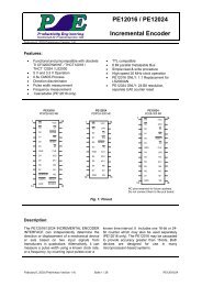
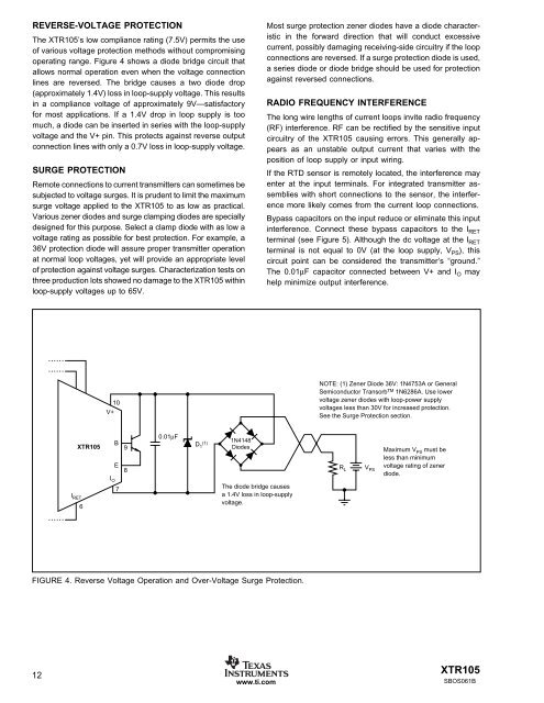
REVERSE-VOLTAGE PROTECTION<br />
The XTR105’s low compliance rating (7.5V) permits the use<br />
of various voltage protection methods without compromising<br />
operating range. Figure 4 shows a diode bridge circuit that<br />
allows normal operation even when the voltage connection<br />
lines are reversed. The bridge causes a two diode drop<br />
(approximately 1.4V) loss in loop-supply voltage. This results<br />
in a compliance voltage of approximately 9V—satisfactory<br />
for most applications. If a 1.4V drop in loop supply is too<br />
much, a diode can be inserted in series with the loop-supply<br />
voltage and the V+ pin. This protects against reverse output<br />
connection lines with only a 0.7V loss in loop-supply voltage.<br />
SURGE PROTECTION<br />
Remote connections to current transmitters can sometimes be<br />
subjected to voltage surges. It is prudent to limit the maximum<br />
surge voltage applied to the XTR105 to as low as practical.<br />
Various zener diodes and surge clamping diodes are specially<br />
designed for this purpose. Select a clamp diode with as low a<br />
voltage rating as possible for best protection. For example, a<br />
36V protection diode will assure proper transmitter operation<br />
at normal loop voltages, yet will provide an appropriate level<br />
of protection against voltage surges. Characterization tests on<br />
three production lots showed no damage to the XTR105 within<br />
loop-supply voltages up to 65V.<br />
12<br />
I RET<br />
XTR105<br />
6<br />
V+<br />
I O<br />
10<br />
B<br />
E<br />
7<br />
9<br />
8<br />
0.01µF<br />
D 1 (1)<br />
1N4148<br />
Diodes<br />
The diode bridge causes<br />
a 1.4V loss in loop-supply<br />
voltage.<br />
FIGURE 4. Reverse Voltage Operation and Over-Voltage Surge Protection.<br />
www.ti.com<br />
Most surge protection zener diodes have a diode characteristic<br />
in the forward direction that will conduct excessive<br />
current, possibly damaging receiving-side circuitry if the loop<br />
connections are reversed. If a surge protection diode is used,<br />
a series diode or diode bridge should be used for protection<br />
against reversed connections.<br />
RADIO FREQUENCY INTERFERENCE<br />
The long wire lengths of current loops invite radio frequency<br />
(RF) interference. RF can be rectified by the sensitive input<br />
circuitry of the XTR105 causing errors. This generally appears<br />
as an unstable output current that varies with the<br />
position of loop supply or input wiring.<br />
If the RTD sensor is remotely located, the interference may<br />
enter at the input terminals. For integrated transmitter assemblies<br />
with short connections to the sensor, the interference<br />
more likely comes from the current loop connections.<br />
Bypass capacitors on the input reduce or eliminate this input<br />
interference. Connect these bypass capacitors to the IRET terminal (see Figure 5). Although the dc voltage at the IRET terminal is not equal to 0V (at the loop supply, VPS), this<br />
circuit point can be considered the transmitter’s “ground.”<br />
The 0.01µF capacitor connected between V+ and IO may<br />
help minimize output interference.<br />
NOTE: (1) Zener Diode 36V: 1N4753A or General<br />
Semiconductor Transorb TM 1N6286A. Use lower<br />
voltage zener diodes with loop-power supply<br />
voltages less than 30V for increased protection.<br />
See the Surge Protection section.<br />
R L<br />
V PS<br />
Maximum V PS must be<br />
less than minimum<br />
voltage rating of zener<br />
diode.<br />
XTR105<br />
SBOS061B