8_Dental_Radiography
8_Dental_Radiography
8_Dental_Radiography

You also want an ePaper? Increase the reach of your titles
YUMPU automatically turns print PDFs into web optimized ePapers that Google loves.
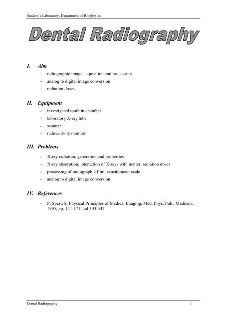
Student’s Laboratory, Department of Biophysics<br />
I. Aim<br />
- radiographic image acquisition and processing<br />
- analog to digital image conversion<br />
- radiation doses<br />
II. Equipment<br />
- investigated tooth in chamber<br />
- laboratory X-ray tube<br />
- scanner<br />
- radioactivity monitor<br />
III. Problems<br />
- X-ray radiation, generation and properties<br />
- X-ray absorption, interaction of X-rays with matter, radiation doses<br />
- processing of radiographic film; sensitometer scale<br />
- analog to digital image conversion<br />
IV. References<br />
- P. Sprawls, Physical Principles of Medical Imaging, Med. Phys. Pub., Madison,<br />
1995, pp. 141-171 and 303-342<br />
<strong>Dental</strong> <strong>Radiography</strong> 1
Student’s Laboratory, Department of Biophysics<br />
V. Detailed instruction<br />
Exercise preparation. Set up a new folder on your private network drive (U). All files<br />
created during the exercise should be saved in this folder. Any files saved at different<br />
locations, will be deleted.<br />
Setting optimal time of exposition of the radiographic films.<br />
Properties of the radiographic film may be defined by using the sensitometer scale<br />
(dependence of the blackening of the film upon the exposition). Radiogram with the<br />
sensitometer scale for this lab was done in such a way: rectangle 1 (lightest) on the scale<br />
was irradiated with X-ray produced by the lamp with anode voltage 30 kVp, anode<br />
current 3 μA and the time of exposition 1s. Every next rectangle was irradiated using<br />
twice larger exposition (3, 6, 12, 24…and so on, in μAs).<br />
Turn on scanner Agfa SnapScan 1236u and apply program Scan Wise (see Section VI)<br />
for scanning one of the sensitometer scales. Apply resolution 300 dpi. Save file in BMP<br />
format in your folder.<br />
Use Pomiary program (see Section IX) to measure an average value of the grey-scale<br />
level in each of 21 rectangular areas of the sensitometer scale. Write the measured gray<br />
levels in the table.<br />
In Statistica program create the graph of the grey level dependence on exposition (apply<br />
the logarithm scale for exposition). Interpret the graph course.<br />
Decide which exposition should be most accurate to achieve the best contrast for<br />
recognizing differences in absorption (extinction) of radiation by the different regions of<br />
irradiated object.<br />
Taking under attention the fact, that the dentist's rtg plate (film) has the similar<br />
properties to the plate with sensitometer scale, count the optimal exposition as well as<br />
the optimal time of exposition for anodal current equal to 100 μA. These parameters<br />
you will apply for settlement of proper exposition times during collection of the tooth’s<br />
radiograms.<br />
Collection of radiographic pictures of tooth.<br />
Radiograms are prepared with laboratory X-ray lamp XR-100 powered with Eclipse II<br />
power supply (see Section VII). A special radiographic film SD-SPEEDX EXPOSURE<br />
CHART (see Section VIII) is applied.<br />
Place the box with a tooth in the openable chamber in column with the X-ray lamp.<br />
Since radiation is created by the laboratory XR-lamp in form of a narrow cylinder<br />
(about 2 cm of diameter), the tooth has to be located exactly in centre of the chamber.<br />
Turn on the power unit of the lamp and set the anodal current equal to 100 μA.<br />
Four radiograms have to be done using the different settings of anodal voltage and<br />
different times of exposition (emission of radiation must be turn on and off manually;<br />
check time of exposition with your clock or stopper):<br />
(1) anodal voltage equal to 30 kVp; time of exposition equal to calculated earlier optimal<br />
time of exposition;<br />
(2) anodal voltage equal to 30 kVp; time of exposition half of the calculated earlier<br />
<strong>Dental</strong> <strong>Radiography</strong> 2
Student’s Laboratory, Department of Biophysics<br />
optimal time of exposition;<br />
(3) anodal voltage equal to 20 kVp; time of exposition equal to calculated earlier optimal<br />
time of exposition;<br />
(4) anodal voltage equal to 20 kVp; time of exposition twice than calculated earlier optimal<br />
time of exposition.<br />
Before irradiating films you should inform the assistant about all calculated parameters of<br />
exposition.<br />
After performing the all expositions, films should be developed according to the instruction<br />
(see Section VIII) and rinsed (the least by two minutes) in current cold water. Then leave<br />
radiograms to full drying.<br />
Dried films should be scanned (see Section VI), the best with resolution of 600 dpi, and<br />
record on disc of your team. The examples of test radiograms are presented in the Fig. V. 1.<br />
Fig. V. 1. Example radiograms of tooth made with laboratory X-ray lamp for three different<br />
settings of exposition parameters (voltages and times of exposition). There are<br />
marked possible regions chosen for contrast determination.<br />
Analysis of all digital radiograms.<br />
In this part make the quantitative analysis of radiograms quality and check finally<br />
if the calculated parameters of exposition were chosen optimally. The quantitative analysis<br />
will be conducted by enumeration and comparison of the contrasts on all digital<br />
radiograms of the tooth. To establish differences in contrast of particular radiograms<br />
(Fig. V. 1.) we have to measure the average degree of the grey-scale level of the chosen<br />
darker region of the tooth in the picture (ID), the average degree of the grey-scale level of<br />
different, lighter region (background) of the tooth (IB) and calculate contrast (K) using<br />
equation [1]:<br />
I B I<br />
D K I<br />
[1]<br />
Measurements should be done for all radiograms always in the same areas of the tooth;<br />
the sizes of analysed surfaces should also be similar (e.g. 40 x 40 pixels).<br />
For execution measurements of the grey-scale levels use the Pomiary program (see<br />
Section IX).<br />
Make the report on the basis of the <strong>Radiography</strong> template. You<br />
can access the template on T: drive. Follow instruction in the<br />
template to prepare the Report.<br />
<strong>Dental</strong> <strong>Radiography</strong> 3<br />
B<br />
IB<br />
ID
Student’s Laboratory, Department of Biophysics<br />
VI. Manuals for Scanner Agfa SnapScan 1236u and ScanWise program<br />
Program ScanWise makes possible scanning documents, pictures, slides, radiograms<br />
and so on using of colourful scanner Agfa SnapScan 1236u installed in the system.<br />
After placing document in scanner close cover and start the program clicking twice<br />
ScanWise icon. On the screen appears the window of ScanWise program with previously<br />
scanned document visible (Fig. VI. 1.).<br />
1) Preliminary scanning.<br />
The first operation executes with scanner after achieving temperature of work is<br />
preliminary scanning (Preview) and displaying in window of preview the results.<br />
Dimensions and position of frame box in Preview image we can change with help of the<br />
left mouse's key, establishing what size we want to scan. Scanned area should contain all<br />
important for further work elements. After exchange of the document on a new one we<br />
should execute preliminary scanning always first, in this aim press the key Preview in the<br />
upper part of screen.<br />
Fig. VI. 1. The start window of the ScanWise program.<br />
2) The settlement of mode of work.<br />
Scanner makes possible scanning of pictures, paintings, text (mode "reflective”) as well as<br />
scanning of slides, negatives, X-ray films (mode ”transparent”). The mode of work is<br />
chosen in upper part of the window of program.<br />
<strong>Dental</strong> <strong>Radiography</strong> 4
Student’s Laboratory, Department of Biophysics<br />
3) Options of the program.<br />
Options of the program are grouped<br />
below key Preview in several groups:<br />
Oryginal Type, Destination, Image<br />
Control and Dimensions. The<br />
appearance of panel changes in<br />
dependence on choice of the option and<br />
shows second level options in the left<br />
side of screen (on the drawing it is<br />
showed for option Oryginal type<br />
opened).<br />
Fig. VI. 2. Details of the the ScanWise<br />
program main window: Options setting.<br />
4) The settlement of type of document to scanning.<br />
In dependence on what kind of document has to be scanned, scanner in different way<br />
optimizes its work. Option Oryginal Type permits to choose type of document what has to<br />
be scanned. In case of work in transparent mode to choice are only two types: Slide and<br />
Negative. For scanning X-ray films we choose option Slide.<br />
5) Place of destination of digital painting.<br />
Digital image is placed after scanning in memory of the computer. Its place of destination<br />
should be defined before scanning. Option Destination gives several possibilities of<br />
choice. During laboratory choose option of the recording images in files of BMP type on<br />
your disc, in aim of processing. To record image on disc in file we choose second level<br />
option File, unlocking dialogue little window, you should qualify: the name of file (File<br />
Name), the location (Path) and the type of file (File type). We record all files in team<br />
folder (!), under any name, and as type of file we choose Bitmaps file (“name".bmp).<br />
During scanning the next fragments of document or the next document, the program will<br />
use the same, chosen by us name adding the next numbers, and do it so long, until we do<br />
not change the name of target file.<br />
6) Matching quality of image.<br />
The option of Image Control makes possible matching with sliders quality of images:<br />
defining the clearness (brightness), the contrast (contrast), the saturation (saturation) and<br />
the threshold (threshold). Number and the kind of accessible options depends on kind of<br />
painting that we want to get. The type of painting (or the number of colours of painting) we<br />
choose using three keys: Color (the colourful painting), Grayscale (painting with using the<br />
grey-scale), LineArt (the black and white painting). In case of colourful paintings and in<br />
scale of greyness the additional filter is including also (option PhotoGenie).<br />
During scanning the sensitometer scale do not alter the value of clearness and the contrast,<br />
we do not use the additional filter also. We choose as type of the painting Grayscale.<br />
7) The settlement of size and the resolution of painting.<br />
The option Dimensions permits to choose the quality of painting across setting the<br />
resolution. This may be realised in different ways, establishing the linear dimensions of<br />
painting with known resolution or altering scale; we can change resolution also. The<br />
change of dimensions does not mark the change of sizes of area marked in field Preview,<br />
<strong>Dental</strong> <strong>Radiography</strong> 5
Student’s Laboratory, Department of Biophysics<br />
but the size of outcome digital painting creating by use of chosen resolution. The important<br />
information what displays program is the size of file created. We should always choose the<br />
compromise among size of file and his quality. For the sensitometer scale scanning we<br />
should choose resolution of 300 dpi.<br />
8) Scanning.<br />
To start scanning, after settlement of way of work scanner, the sizes of file, his approach<br />
the location and so on, click the large, red, round button with inscription Scan.<br />
<strong>Dental</strong> <strong>Radiography</strong> 6
Student’s Laboratory, Department of Biophysics<br />
VII. Manuals for the XR-100 laboratory X-ray tube and Eclipse II<br />
power supply.<br />
XR-100 X-ray tube is the laboratory device producing small intensity X-ray radiation.<br />
The tube is installed in the upper part of the aluminum box filled with the lead. The vertical<br />
position of the tube (its distance from the phantom) may be set with the knob. Phantom is<br />
placed in the central opened space. Below, inside the box the intensifying radiographic screen<br />
and the CCD camera for registration of the digital images are placed (Fig. VII.1.):<br />
Fig. VII.1. Experimental unit for angiographic and radiographic measurements<br />
with the power supply.<br />
Attention. High voltage power supply Eclipse II (Fig. VII.2.) is very easy for<br />
malfunctioning and it is strongly important to applied in details the<br />
manuals or asking assistant for help.<br />
Operation of the X-Ray tube XR-100 and high voltage power supply Eclipse II:<br />
1. Turning of the X-ray tube power supply ON and OFF should be done under supervising of<br />
the assistant.<br />
2. Turn ON the power supply with the Power switch (rear panel).<br />
The X-ray tube setting knob<br />
Upper aluminum box with internal<br />
lead core and X-ray tube XR-100<br />
inside<br />
Open space in the experimental unit<br />
for placing the investigated object<br />
Intensifying screen (inside the<br />
bottom box)<br />
CCD camera (inside the bottom<br />
box)<br />
Main power ON/OFF (in the rear<br />
panel of the power supply)<br />
Power supply Eclipse II<br />
3. Press and hold the button Preset and set the proper parameters U [kV] and I [μA] with<br />
knobs E and F respectively (Fig. VII.2.).<br />
4. Emission of the radiation begins after turning the Enable switch ON and lasts up to<br />
turning it OFF.<br />
<strong>Dental</strong> <strong>Radiography</strong> 7
Student’s Laboratory, Department of Biophysics<br />
Attention. If the yellow lamp Fault will light during the measurements turn<br />
the Enable switch OFF and ask the assistant.<br />
5. After finishing measurements turn the Power switch OFF (rear panel).<br />
A<br />
B C D E F<br />
Fig. VII.2. The front panel of the power supply Eclipse II:<br />
A – ON/OFF of the radiation emission (Enable);<br />
B – HV (High Voltage) - red lamp signaling the operation of the X-ray tube;<br />
C – Fault, alarm signal lamp for malfunction of the unit<br />
D – button for setting the power supply parameters (Preset);<br />
E – setting and display of the high voltage in the X-ray tube;<br />
F – setting and display of the current in the X-ray tube.<br />
<strong>Dental</strong> <strong>Radiography</strong> 8
Student’s Laboratory, Department of Biophysics<br />
VIII. Procession of the SD-SPEEDX EXPOSURE CHART<br />
Procession step-by-step (steps 4 to 8 must be done without any breaks):<br />
<strong>Dental</strong> <strong>Radiography</strong> 9
Student’s Laboratory, Department of Biophysics<br />
After washing (no less than 2 minutes) the developed film have to be fully<br />
dried before placing in the scanner for producing the digital version of the tooth<br />
radiogram.<br />
<strong>Dental</strong> <strong>Radiography</strong> 10
Student’s Laboratory, Department of Biophysics<br />
IX. Distance, area and grey-scale level measurements –<br />
Pomiary program<br />
The Pomiary program allows geometrical measurements on images saved in the BMP<br />
format. It is possible to measure:<br />
(1) distances,<br />
(2) areas of rectangular and elliptical structures,<br />
(3) an average value of the grey-scale level in rectangular and elliptical structures,<br />
(4) an area of any structure on binary image.<br />
Attention. To allow the distance measurement it is necessary to set the appropriate<br />
image resolution first (see point 6).<br />
In the cases of (1), (2) and (4) it is possible to choose one of four accessible units:<br />
millimeters, centimeters, inches or pixels.<br />
The program window is showed in Fig. IX.1.<br />
1<br />
2<br />
3<br />
4<br />
Fig. IX.1. The Pomiary program main window: 1 – main menu, 2 – toolbar, 3 – opened image<br />
window, 4 – status bar, 5 – measurement tools, 6 – image resolution panel, 7 –<br />
unit panel, 8 – shape panel (see text for details).<br />
Details of the application of the Pomiary program:<br />
1) Main menu bar. The main menu options open sub-menus.<br />
2) Toolbar. The buttons placed in the toolbar have the same function as the most important<br />
options in the main menu.<br />
<strong>Dental</strong> <strong>Radiography</strong> 11<br />
5<br />
6<br />
7<br />
8
Student’s Laboratory, Department of Biophysics<br />
3) Image window. It is possible to open more than one image at the same time. Management<br />
of all opened windows is performed with: the Okno (Window) option in the Main menu,<br />
or the three last buttons in the Toolbar.<br />
4) Status bar. There is an additional help displayed in the status bar when some window<br />
elements are pointed with the cursor.<br />
5) Measurement tools.<br />
area<br />
distance measurements<br />
measurements of the area of elliptical or rectangular regions<br />
measurements of the area of any shape on the binary image<br />
measurements of the average grey-scale level of a rectangular or elliptical<br />
remove the measurement results from the image (all)<br />
zoom out / zoom in<br />
The first step in all measurements is to mark a region or a distance, which will be<br />
measured. In order to define the line segment, click with the left mouse button the start point<br />
and pressing the mouse button drag to the segment end. The area can be defined in the same<br />
way but in this case an area diagonal is defined.<br />
6) Image resolution panel: Rozdzielczość (resolution). There are three edit boxes connected<br />
to the image resolution setting. The image resolution in Rozdzielczość edit box should be<br />
expressed in dpi units (dot per inch). The Rozdzielczość edit box can be used when the<br />
real image resolution is known. In that case the pxl edit box displays number of pixels<br />
within the unit distance (the unit can be defined in Jednostki panel - see point 7).<br />
Use the procedure described below to calculate the image resolution if the real image<br />
resolution is not known:<br />
a) Find the known distance on the image (e.g. a scale visible on the picture, total width of<br />
the radiogram film or any defined, given dimension),<br />
b) Check pixel unit in Jednostki panel,<br />
c) Measure the known distance using the pixel unit and remember (or mark in the<br />
picture) the result,<br />
d) Change the unit in Jednostki panel accordingly to your needs and put the result into<br />
the pxl edit box,<br />
<strong>Dental</strong> <strong>Radiography</strong> 12
Student’s Laboratory, Department of Biophysics<br />
e) Put the real measured distance expressed in chosen unit into the third, left edit box<br />
designed for the real distances in Rozdzielczość panel. It is labeled by the unit chosen<br />
in point d.<br />
7) Unit panel: Jednostki (units). The Jednostki panel allows a choice of units used for the<br />
measurement. It is possible to choose between millimeters, centimeters, inches and pixels.<br />
When the last option is checked (pixel) all distances will be expressed in image pixel unit.<br />
8) Shape panel: Kształt obszaru (area shape). In the case of area measurements it is<br />
necessary to define the area shape. The rectangular and elliptical shapes can be measured.<br />
Help in the program. Like most applications in MS Windows system the Pomiary<br />
program displays help (the short messages concerning the object pointed by the cursor, in<br />
Polish) as labels nearby the cursor or as a text in the status bar. Point a desired element and<br />
wait few seconds without any button click.<br />
How to open an image file? The image file can be opened by the main menu option Plik<br />
(file) and Otwórz (open) sub-option. The Otwórz dialog window appears. It can be activated<br />
also by the first button ( ) in the toolbar.<br />
How to save an image file? The results of measurement are marked on the image. It is<br />
possible to save the image with marked results. Choose Plik option and Zapisz (save) suboption<br />
in order to save the image with the original name. In order to save the image with<br />
a new name, choose Plik option and Zapisz jako (save as) sub-option.<br />
How to use clipboard? The program allows copying the whole image to the clipboard.<br />
The image saved in the clipboard is accessible from all applications run in the system. The<br />
clipboard is the easiest way to move the image to other applications. In order to copy the<br />
image from an active window, choose Edycja (edit) menu option and the sub-option Kopiuj<br />
(copy). It is possible to use the toolbar too. The third button from the left has the same<br />
meaning as the Edycja->Kopiuj option.<br />
<strong>Dental</strong> <strong>Radiography</strong> 13