
Create successful ePaper yourself
Turn your PDF publications into a flip-book with our unique Google optimized e-Paper software.
SECTION 02 FPGA DEVICE SUPPORT NANOBOARD-NB1 2004<br />
12<br />
CPLD <strong>Device</strong>s<br />
Xilinx ®<br />
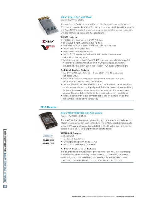
Virtex-II Pro with SRAM<br />
<strong>Device</strong>: XC2VP7-5FG456C<br />
The Virtex ®<br />
-II Pro family contains platform FPGAs for designs that are based on<br />
IP cores and customized modules. The family incorporates multi-gigabit transceivers<br />
and PowerPC CPU blocks. It empowers complete solutions for telecommunication,<br />
wireless, networking, video, and DSP applications.<br />
XC2VP7 features:<br />
11,088 logic cells arranged in 4,928 CLB slices<br />
Up to 9,856 4-input LUTs and 9,856 flip-flops<br />
Block RAM (to 792K bits) and distributed RAM (to 154K bits)<br />
4 digital clock managers (DLLs)<br />
16 global clock multiplexer buffers<br />
Support for 32 selectable I/O standards with fast or slow slew rates<br />
and multiple drive strengths<br />
The device contains a ‘hard’ PowerPC 405 processor core, which is supported<br />
in Nexar by a complete tool-chain (TASKING Viper compiler, source level<br />
debugger, etc) that allows use of this device in FPGA-based system designs<br />
Additional daughter features:<br />
Two IDT71V416L static RAM ICs – 4 Meg (256K x 16) 10ns advanced<br />
high-speed CMOS<br />
One MAX1617 SMBus temperature sensor which measures FPGA chip<br />
temperature and internal sensor temperature<br />
Interface to two of the high speed (3.125GHz) transceivers in the Virtex-II Pro –<br />
each transceiver channel has 4 gold plated SMA coax connectors mounted along<br />
the top of the daughter board (transceivers are used with the programmable<br />
on-board Nanoboard clock that limits their speed to between 1 and 2GHz)<br />
The board comes with 8 coax connector cables and an example project that<br />
demonstrates the use of the transceivers<br />
Altera ®<br />
MAX ®<br />
3000/7000 with PLCC sockets<br />
<strong>Device</strong>: EPM7032AELC44-10<br />
The MAX ®<br />
family of devices are high-density, high performance devices based on<br />
Altera’s second-generation MAX architecture. The EEPROM-based devices operate<br />
with a 3.3-V supply voltage and provide 600 to 10,000 usable gates and counter<br />
speeds of up to 303.0 MHz, dependant on specific device.<br />
EPM7032AE features:<br />
32 macrocells<br />
2 dedicated global clocks<br />
3.3V supply voltage with 2.5 to 5V I/Os<br />
Support for 2 selectable I/O standards<br />
Additional daughter board features:<br />
The daughter board includes one 44 pin and one 84 pin PLCC socket providing<br />
support for any of the following devices: EPM3032A, EPM3064A, EPM7032S,<br />
EPM7064S, EPM7128S, EPM7160S, EPM7032AE, EPM7064AE, EPM7128AE,<br />
EPM7032B, EPM7064B, EPM7032S, EPM7064S, EPM7128S, EPM7160S.<br />
NanoBoard-NB1 2004 – LiveDesign-enabled FPGA-based development board www.altium.com/nanoboard