High Voltage Control Unit Typ HST 01/01 - SCHNIER Elektrostatik ...
High Voltage Control Unit Typ HST 01/01 - SCHNIER Elektrostatik ...
High Voltage Control Unit Typ HST 01/01 - SCHNIER Elektrostatik ...

You also want an ePaper? Increase the reach of your titles
YUMPU automatically turns print PDFs into web optimized ePapers that Google loves.
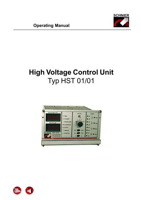
Operating Manual<br />
<strong>High</strong> <strong>Voltage</strong> <strong>Control</strong> <strong>Unit</strong><br />
<strong>Typ</strong> <strong>HST</strong> <strong>01</strong>/<strong>01</strong>
Operating Manual<br />
Inhaltsverzeichnis<br />
1.0 General Information<br />
2.0 Safety<br />
3.0 Technical-<br />
Data<br />
4.0 Design<br />
Description<br />
5.0 Functional<br />
Description<br />
6.0 Busmodule<br />
7.0 Spare Parts and<br />
After Sales Servicet<br />
1.1 Introduction<br />
1.2 Scope of Application<br />
2.1 Labor Protection Symbol<br />
2.2 Warning Label<br />
2.3 General Safety Notes<br />
2.4 Special Safety Notes<br />
3.1 General Notes<br />
3.2 Supply <strong>Voltage</strong>s<br />
3.3 Setting Values<br />
3.4 Inputs<br />
3.5 Outputs<br />
4.1 Subassemblies<br />
4.2 General Notes<br />
4.3 Panel Overview<br />
4.4 Indicating Instruments<br />
4.5 <strong>Control</strong> LED´s<br />
4.6 Switches<br />
4.7 Trim Potentiometers<br />
4.8 <strong>Control</strong> <strong>Unit</strong> Mounting<br />
5.1 Constant <strong>Voltage</strong> Operation<br />
5.2 Constant Current Operation<br />
6.1 Overview<br />
6.2 Mains Supply<br />
6.3 HV Generator Connection<br />
6.4 External Supplies<br />
6.5 Inputs and Outputs<br />
6.6 Earth reversing switch connections<br />
Nr. 81<strong>01</strong>23BE_02/00<br />
Page2 of 17
Operating Manual<br />
1.0 General Information<br />
1.1 Introduction<br />
1.2 Scope of Application<br />
This Operating Manual (in the following called OM) has to be read,<br />
fully understood and observed in all respects by all persons who<br />
are responsible for the devices and the electrostatic installation.<br />
For these reasons the OM should always be available to the<br />
operating, maintenance and service personal.<br />
Only with the knowledge of this OM faults can be avoided and a<br />
trouble-free operation be guarenteed. Therefore it is important<br />
that the OM is known to all persons involved. The company<br />
<strong>SCHNIER</strong> <strong>Elektrostatik</strong> GmbH will not assume any responsibility<br />
resulting from the failure to comply with the OM!<br />
The HV control unit may only be used in electrostatic coating<br />
installations within the temperature range of 10°C to 40°C and a<br />
relative humidity of between 35% to 80%. Furthermore the relevant<br />
safety notes according to points 2.3 and 2.4 of this OM<br />
must be strictly observed.<br />
The HV control unit HS <strong>01</strong>/<strong>01</strong> has to be only operated with the<br />
high voltage generators of the medium frequency types supplied.<br />
by the company <strong>SCHNIER</strong> <strong>Elektrostatik</strong> GmbH.<br />
Nr. 81<strong>01</strong>23BE_02/00<br />
Page 3 of 17
2.0 Safety<br />
Operating Manual<br />
2.1 Labor Protection Symbol<br />
2.2 Warning Label<br />
2.3 Special Safety Notes<br />
2.4 General Safety Notes<br />
This symbol marks all notes which might lead to danger for life<br />
and limb of persons if they are not observed. Please observe<br />
them and be especially careful in these cases.<br />
Apart from the notes in this OM the general valid safety instructions<br />
as well as the regulation for the prevention of accidents must be<br />
adhered to.<br />
Attention!<br />
Nr. 81<strong>01</strong>23BE_02/00<br />
Page 4 of 17<br />
This attention label will be displayed in this OM whenever there is<br />
an important note to be observed in order to avoid damage or<br />
destruction of the device.<br />
The HV control unit may only be used for stationary spraying<br />
installations which fulfill the relevant safety requirements.<br />
The safety notes under point 2.4 are To be observed most stringently,<br />
especially:<br />
EN 50 176<br />
EN 50 177<br />
EN 50 223<br />
EN 50 348<br />
DIN VDE <strong>01</strong>47 SEC. 1<br />
Moreover, the operating instruction of the resp. electrostatic<br />
plant has to be observed!<br />
See data sheet “Vorschriften und Regeln” no. 810002DD<strong>01</strong>.
3.0 Technical Data<br />
3.1 General Notes<br />
3.2 Supply voltages<br />
3.3 Setting Values<br />
Operating Manual<br />
Device designation HV control unit<br />
Model <strong>HST</strong> <strong>01</strong>/<strong>01</strong><br />
Dimensions H/W/L 3 HE/42 TE / 232,5mm<br />
Serial number see label<br />
Year of construction see label<br />
The control unit can be powered in the following two ways:<br />
a) Internal supply module<br />
SEVM 1<strong>01</strong><br />
connection via X1<br />
b) External power<br />
supplies<br />
connection via X3<br />
230 V / 50-60 Hz 150VA<br />
36 V AC + 10% /<br />
50- 60 Hz 120 VA<br />
24 V DC + 10 %/20VA<br />
The following setting values depend on the employed HV generator<br />
a) Constant voltage operation<br />
Static current<br />
disconnection treshold :<br />
<strong>High</strong> voltage: 0- >100 kV, stepless<br />
adjustment<br />
Dynamic current<br />
disconnection (di/dt): 0- >980 µA/s<br />
<strong>High</strong> voltage ramp rate: approx. 3s (fixed)<br />
b)Constant current operation<br />
Nr. 81<strong>01</strong>23BE_02/00<br />
Page 5 of 17<br />
Current limitation: 0- >800 µA, stepless<br />
adjustment<br />
<strong>Voltage</strong> limitation: 0- >100 kV, stepless<br />
adjustment<br />
Dynamic voltage<br />
disconnection (du/dt) 0- >100 kV/s<br />
Static voltage<br />
disconnection treshold 36 kV (fixed)<br />
<strong>High</strong> voltage ramp rate approx. 3s (fixed)
Operating Manual<br />
3.4 Inputs HV on 24 V DC<br />
Stage 1 24 V DC<br />
Stage 2 24 V DC<br />
Stage 3 24 V DC<br />
Stage 4 24 V DC<br />
Stage 5 ( analog ) 24 V DC<br />
I or U operation 24 V DC<br />
3.5 Outputs<br />
Analog outputs for<br />
instruments<br />
Inputs for analog setting of nominal value<br />
U nom<br />
0 ... 10 V DC equals<br />
0 ... 100 kV<br />
I 0 ... 10 V DC equals<br />
nom<br />
0 ... 1 mA<br />
du or di / dt 0 ... 10 V DC equals<br />
0 ... 100 kV/s<br />
or 0 ... 1mA /s<br />
Fault: 24V DC max 100mA<br />
Release: 24V DC max 100mA<br />
Pre-warning: 24V DC max 100mA<br />
HV on 24V DC max 100mA<br />
Earth reversing switch 24V DC max 100 mA,<br />
adjustable disconnection<br />
delay between 0,1and 5s<br />
U act<br />
I act<br />
0 ... 10 VDC equals<br />
0 ... 100kV<br />
(Ri>100kOhm)<br />
0 ... 10 VDC equals<br />
0 ... 1mA<br />
(Ri >100kOhm)<br />
Nr. 81<strong>01</strong>23BE_02/00<br />
Page 6 of 17
Operating Manual<br />
4.0 Design Description<br />
4.1 Subassemblies<br />
4.2 General Notes<br />
Nr. 81<strong>01</strong>23BE_02/00<br />
Page 7 of 17<br />
The HV control unit <strong>HST</strong> <strong>01</strong>/<strong>01</strong> consists of the following<br />
components:<br />
-<strong>Control</strong> module SESM 1<strong>01</strong><br />
-Power module SELM 1<strong>01</strong><br />
-Front module SEFM 1<strong>01</strong><br />
-Bus module SEBM 102<br />
-External supply module SEVM 1<strong>01</strong> (optional)<br />
The high voltage control unit <strong>HST</strong> <strong>01</strong>/<strong>01</strong> is designed for the operation<br />
of HV generators ot the medium frequency types.<br />
According to the selected operation mode (I constant or U constant)<br />
the voltage or the current can be defined in 5 stages and can be<br />
adjusted between 0 and 100% of U nom. or I nom.<br />
For each stage there is a static and a dynamic dis-connection<br />
treshold (for more details see 4.4 and 4.5).
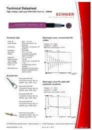
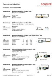
4.3 Übersichtsbild<br />
General<br />
Operating Manual<br />
4<br />
3<br />
2<br />
1<br />
1 Fixing screw<br />
2 Handle bar<br />
Adjustment potentiometers<br />
14 kV adjust stage 1<br />
15 µA adjust stage 1<br />
16 Dynamic adjust stage 1<br />
17 kV adjust stage 2<br />
18 Dynamic adjust stage 2<br />
19 µA adjust stage 2<br />
20 kV adjust stage 3<br />
21 Dynamic adjust stage 3<br />
22 µA adjust stage 3<br />
23 Dynamic adjust stage 4<br />
24 kV adjust stage 4<br />
25 µA adjust stage 4<br />
5 6 7 8 9 10 11 12 13 14 15<br />
28 27 26 25<br />
Visual displays and LED's<br />
3 Display for µA and fordynamic disconnection<br />
4 Display for kV<br />
5 LED for release signal<br />
6 LED for power on<br />
7 LED for warning<br />
8 LED for static disconnection (U or I)<br />
9 LED for dynamic disconnection (U or I)<br />
10 LED for constant current mode<br />
11 LED for constant voltage mode<br />
Switches<br />
16<br />
17<br />
18<br />
19<br />
20<br />
21<br />
22<br />
23<br />
24<br />
Nr. 81<strong>01</strong>23BE_02/00<br />
Page 8 of 17<br />
12 HV on<br />
13 Set point selection switch<br />
26 Selection of µA or Dyn.<br />
27 Selection of actual or nominal value<br />
28 Selection of current or voltage mode<br />
(only analog step)
4.4 Indicating<br />
Instruments<br />
4.5 <strong>Control</strong> LED's<br />
1. Power on LED (6)<br />
2.Release LED (5)<br />
3.Warning LED (7)<br />
4.U/I static LED (8)<br />
5.U/I dynamic LED (9)<br />
Operating Manual<br />
6.Current mode LED (10)<br />
7.<strong>Voltage</strong> mode LED (11)<br />
4.6 Switches<br />
Nr. 81<strong>01</strong>23BE_02/00<br />
Page 9 of 17<br />
In the HV control unit <strong>HST</strong> <strong>01</strong>/<strong>01</strong>, there are two digital instruments.<br />
The top digital display (4) is for the kV. Dependent on the position<br />
of the Nominal/Actual Value Switch (27) it indicates the exact<br />
nominal or actual value of the output voltage.<br />
The lower digital display (3) is for µA (3). It also indicates the<br />
exact nominal or actual value of the output current, dependent on<br />
the position of the Nominal/Actual Value Switch (27). In addition<br />
the actual values can also externally be evaluated or displayed<br />
via the bus module (for more details see Technical Data, page<br />
11).<br />
With the selection switch (26) in the Dyn. position, the dynamic<br />
disconnection value can be displayed. In this case the nominal<br />
value is indicated in any of the two positions of the selection switch<br />
(27) for nominal or actual value.<br />
The HV control unit <strong>HST</strong> <strong>01</strong>/<strong>01</strong> has seven control LED's which<br />
are as follows:<br />
This LED is on when the internal power supply is functioning<br />
correctly.<br />
This LED is on when 80% of U or I is achieved<br />
nom nom<br />
This LED is on when 80% of the adjusted static disconnection<br />
treshold is reached<br />
This LED is on after triggering of the static current or voltage<br />
disconnection treshold.<br />
This LED is on after triggering of the dynamic current or voltage<br />
disconnection treshold.<br />
This LED is on when the selected stage is in current mode.<br />
This LED is on when the selected stage is in voltage mode.<br />
The HV control unit <strong>HST</strong> <strong>01</strong>/<strong>01</strong> has five function switches on<br />
the front plate.<br />
The switches (26) for µA or Dyn. and (27) for nominal or actual<br />
value are only used for the digital displays as described in 4.4.<br />
The HV on switch (12) serves as master switch.
Operating Manual<br />
Attention!<br />
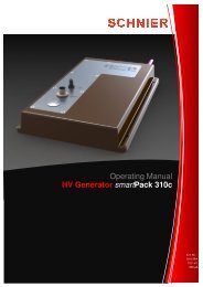
4.7 Trim Potentiometers<br />
Attention!<br />
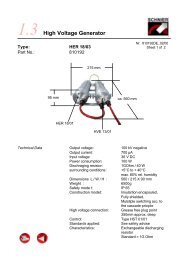
fig.1<br />
On the front plate of the HV control unit high voltage cannot be<br />
activated without an additional external release signal (for<br />
instance key switch or PLC signal). Only with the HV-on switch<br />
(12) in the on position and the external HV-on signal present,<br />
high voltage is generated.<br />
The multiple contact switch (13) is for selection of single stages.<br />
The HV control unit has 5 stages. For the stages 1 to 4 the<br />
nominal values for kV, µA and Dyn can be adjusted using the<br />
trim potentiometers located on the unit's front plate. The stage 5<br />
(analog) nominal values for kV, µA and Dyn can be defined<br />
externally using analog voltages (0 ... 10 V DC). Stage 5 cannot<br />
be selected via the multiple contact switch (13), but externally<br />
with the switch (13) in the "External" position.<br />
This works the same way also for the externalselection of the<br />
stages 1 to 4. One of the five stages can only be controlled<br />
externally if the multiple contact switch (13) is in the "External"<br />
position.<br />
As already described in 4.6 the high voltage controller S<strong>HST</strong><br />
100/<strong>01</strong> has 4 internally adjustable stages (stage 1 to 4) whose<br />
nominal values for kV, µA and Dyn can be adjusted via 12 trim<br />
potentiometers (14 to 25). There are 3 trim potentiometers per<br />
stage for specifying values from 0 to 100 kV or from 0 to 800 µA<br />
or from 0 to 100 kV/s or from 0 to 1000 µA/s.<br />
The following assignment have been made:<br />
Trim potentiometers for stage 1:<br />
(14) for kV, (15) for µA and (16) for Dyn<br />
Trim potentiometers for stage 2:<br />
(17) for kV, (19) for µA and (18) for Dyn<br />
Trim potentiometers for stage 3:<br />
(20) for kV, (22) for µA and (21) for Dyn<br />
Trim potentiometers for stage 4:<br />
(24) for kV, (25) for µA and (23) for Dyn<br />
It is important that the corect trim tool (see fig. 1) is used as<br />
the use of any other tool could cause damage to the trim<br />
potentiometers<br />
1 trim tool is supplied with every control unit .<br />
Nevertheless additional trim tools can be ordered by stating:<br />
article designation: SEAS<br />
reference no.: 150<strong>01</strong>8<br />
Nr. 81<strong>01</strong>23BE_02/00<br />
Page 10 of 17
Operating Manual<br />
4.8 <strong>Control</strong> <strong>Unit</strong> Mounting<br />
Attention!<br />
5.0 Functional Description<br />
The HV control unit <strong>HST</strong> <strong>01</strong>/<strong>01</strong> is equipped with four knurled screws<br />
secured against loss for attaching the control module to the rack.<br />
The control module must be fastened with all fixing screws to the<br />
rack in order to guarantee perfect electrical contact between the<br />
plug-in connectors and the bus plate bar.<br />
After loosening the fixing screws the control module may only be<br />
pulled out of the rack using the handle bar (2). Never pull out the<br />
control module using the switches instead of the handle bar.<br />
The HV control unit <strong>HST</strong> <strong>01</strong>/<strong>01</strong> is provided with 5 stages. There<br />
is one trim potentiometer for kV, one for µa and one for Dyn for<br />
each of the stages 1 to 4. By means of the trim potentiometers<br />
nominal values between 0 and 100% cvan be adjusted.<br />
For stage 5 (analog) the nominal values are specified via analog<br />
voltages by the superimposed control system (for more details<br />
refer to Technical Data, page11).<br />
For each stage two operating modes are available:<br />
a) constant voltage (U-mode)<br />
b) constant current (I-mode).<br />
Nr. 81<strong>01</strong>23BE_02/00<br />
Page 11 of 17<br />
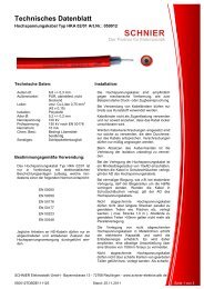
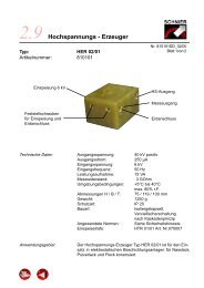
For stages 1 to 4 switching over of the operating modes can only<br />
be carried out internally on the control board SESM 1<strong>01</strong> (see<br />
fig.)<br />
For stage 5 (analog) the change-over may be realized either via<br />
the front plate or externally. The device will be in I-mode after<br />
having selected I-mode from the front plate or externally.
Operating Manual<br />
Attention!<br />
Stage 4<br />
U I<br />
< ><br />
Stage 3<br />
U I<br />
< ><br />
Stage 2<br />
U I<br />
< ><br />
Stage 1<br />
U I<br />
< ><br />
5.1 Constant<br />
<strong>Voltage</strong> Mode<br />
Nr. 81<strong>01</strong>23BE_02/00<br />
Page 12 of 17<br />
Only authorised personnel should be allowed to execute the<br />
operation of switching over on the control board as this requires<br />
the opening of the control unit.<br />
In the constant voltage mode the voltage is increased to the<br />
adjusted nominal value and held constant. When reaching approx.<br />
80% of the desired output voltage the "release" signal is output.<br />
When there is load on the HV output, the output voltage is kept<br />
constant, but only within the power range of the connected HV<br />
generator (see characteristic curve of the HV generator).
5.2 Constant<br />
Current Mode<br />
Operating Manual<br />
Nr. 81<strong>01</strong>23BE_02/00<br />
Page 13 of 17<br />
In the constant voltage mode the static current disconnection<br />
treshold can be adjusted between 0 and approx. 820 µA. When<br />
reaching approx. 80% of the adjusted disconnection treshold the<br />
"warning" signal is generated. As soon as the load decreases,<br />
the signal disappears. If the load nevertheless increases the<br />
controller indicates "fault" when the adjusted treshold value is<br />
reached. <strong>High</strong> voltage then will automatically be switched off. In<br />
order to switch the high voltage on again, the "HV on" signal has<br />
to be surpressed during at least one second either by (12) on the<br />
front plate or by means of the external control system.<br />
The dynamic di/dt disconnection treshold can be adjusted<br />
between 0 and approx. 999 µA/s. This part of the controller<br />
continuously monitors in which time a determined current value<br />
is reached, either during current rise or fall (current slope<br />
steepness). If the current slope is steeper than permitted by the<br />
adjusted value, the controller will indicate "fault". The fault reset<br />
procedure is the same as for static disconnection. The dynamic<br />
disconnection is independent of the static disconnection treshold.<br />
This means that a dynamic disconnection may also be triggered<br />
if the current is significantly below the static disconnection value.<br />
On the front plate of the HV control unit the type of disconnection,<br />
either static of dynamic, will be displayed. In addition a collective<br />
fault is output to the external control system.<br />
In constant current mode the operating current can be adjusted.<br />
This value is kept constant by regulating the output voltage. When<br />
reaching approx. 80% of the adjusted current value the "release"<br />
signal is output. By means of the "kV" nominal value the maximum<br />
admissible operating voltage between 40 and 100 kV can be<br />
limited.<br />
In constant current mode the static voltage disconnection treshold<br />
is fixed to approx. 38 kV. When reaching this value the device<br />
switches off and indicates "fault". In order to switch the high voltage<br />
on again, the "HV on" signal has to be surpressed during at least<br />
one second either by the switch (12) on the front plate or by means<br />
of the external control system. Before the controller disconnects<br />
the "warning" signal is generated at appox. 46 kV.
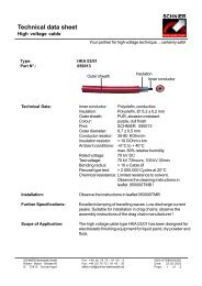
6.0 Bus module<br />
6.1 Overview<br />
Operating Manual<br />
X4<br />
The dynamic du/dt disconnection treshold can be set between 0<br />
and approx. 999 kV/s. This part of the controller continuously<br />
monitors in which time a determined voltage value is achieved,<br />
either during voltage rise or fall (voltage slope steepness). If the<br />
voltage slope is steeper than permitted by the adjustable value<br />
the controller will indicate "fault". The dynamic disconnection is<br />
independent of the static disconnection treshold. This means that<br />
a dynamic disconnection may also be triggered if the voltage is<br />
significantly above the static disconnection value.<br />
On the front plate of the HV control unit the type of disconnection,<br />
either static of dynamic, will be displayed. In addition a collective<br />
fault is output to the external control system.<br />
P1<br />
Nr. 81<strong>01</strong>23BE_02/00<br />
Page 14 of 17<br />
X1<br />
X5<br />
X2<br />
X3
6.2 Main supply<br />
6.3 HV Cascade<br />
Connection<br />
Operating Manual<br />
The power is supplied to connector X1 and is only required with<br />
integrated supply module SEVM 1<strong>01</strong> and is therefore not necessary<br />
in case of external power supply via connector X3.<br />
Pin Designation Signal Function<br />
<strong>01</strong> L1 230V 150VA 50Hz supply voltage<br />
02 N 230V 150VA 50Hz supply voltage<br />
<<br />
03 PE PE<br />
6.4 External Supplies<br />
The HV cascade is connected via connector X2.<br />
Pin Designation Signal Function<br />
<strong>01</strong> R+ 0-36V DC 120 VA supply<br />
02 PEGND 0 ground<br />
03 E+ 17V DC 10VA auxiliary voltage<br />
04 I-Ist 0-10V DC current actual value<br />
05 U-Ist 0-10V DC voltage actual value<br />
Attention!<br />
The external power supply is realized via connector X3 and will<br />
only be required without a supply module integrated, for instance<br />
if various controllers are supplied by a single power supply.<br />
<<br />
<<br />
<<br />
Pin 02 (GND) must be connected to ground.<br />
Pin 03 or 04 (36VAC) must not be grounded.<br />
Pin Designation Signal Function<br />
<strong>01</strong> 24V DC 24V DC 20 VA Steuerspannung<br />
02 GND 0 Masse<br />
03 36V AC2 36V 120VA 50Hz Versorgung HS-Erzeuger<br />
04 36V AC1 36V 120VA 50Hz Versorgung HS-Erzeuger<br />
<<br />
6.4 Inputs and Outputs<br />
6.6 Earth Reversing<br />
Switch Connector X5<br />
Operating Manual<br />
Via connector X4 different inputs and outputs are available.<br />
Pin Bezeichnung Signal Funktion<br />
<strong>01</strong> PEGND 0 Ground<br />
02 U-Ist-Ext 0-10V DC 0,1mA Actual value output<br />
03 I-Ist-Ext 0-10V DC 0,1mA Actual value output<br />
04 HV-On 24V DC 100mA Output<br />
05 Fault 24V DC 100mA Output<br />
06 Relase 24V DC 100mA Output<br />
07 Warning 24V DC 100mA Output<br />
08 DX/DT 0-10V DC Analog nom. value input Dyn.<br />
09 U-Nom. 0-10V DC Analog nom. value input voltage<br />
10 I-Nom. 0-10V DC Analog nom. value input current<br />
11 HV-On 24V DC <strong>Control</strong> signal HV on<br />
12<br />
13<br />
14<br />
15<br />
16<br />
17<br />
Stage 1<br />
Stage 2<br />
Stage 3<br />
Stage 4<br />
Analog Stage<br />
I-Mode<br />
24V DC<br />
24V DC<br />
24V DC<br />
24V DC<br />
24V DC<br />
24V DC<br />
<<br />
Operating Manual<br />
Pin Designation Signal Function<br />
<strong>01</strong> ES 24V DC 100mA Triggering of earth reversing switch<br />
02 GND 0 Ground<br />
03 24V DC 24V DC Supply for feedback signal<br />
04 Feedback. 24V DC Feedback from earth revers. switch<br />
Spare parts and<br />
Service<br />
No guarantee whatsoever is valid, if no original parts are used!<br />
Our address:<br />
<<br />
Schnier <strong>Elektrostatik</strong> GmbH<br />
Robert-Bosch-Straße 60<br />
72810 Gomaringen, Germany<br />
Tel.: +49 (0) 70 72 / 91 43 -0<br />
Fax: +49 (0) 70 72 / 91 43 -20<br />
<<br />
Nr. 81<strong>01</strong>23BE_02/00<br />
Page 17 of 17