Produkt- information Set-Compact-Video SET CV 850-1 bis ... - Siedle
Produkt- information Set-Compact-Video SET CV 850-1 bis ... - Siedle
Produkt- information Set-Compact-Video SET CV 850-1 bis ... - Siedle

You also want an ePaper? Increase the reach of your titles
YUMPU automatically turns print PDFs into web optimized ePapers that Google loves.
English<br />
Mounting<br />
Contents<br />
• Application<br />
• Scope of delivery<br />
• Mounting<br />
• Technical data<br />
Programming plug+play<br />
Programming - manual<br />
• Programming door calls<br />
• Programming door calls at the<br />
handsfree bus telephone<br />
• Programming door calls via the<br />
storey call butto<br />
• Programming internal calls<br />
• Dialling the door station<br />
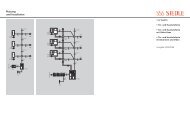
Wiring diagram<br />
14<br />
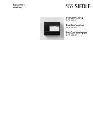
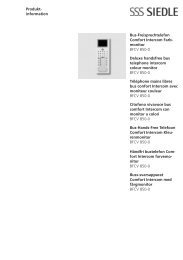
Application<br />
The compact video set for 1 or 2<br />
residential units. Encompasses the<br />
door station for surface mounting,<br />
line rectifier for distributor<br />
mounting (9 TE) and bus telephones<br />
with colour monitor for surface<br />
mounting. With the basic functions<br />
calling, speech, vision and door<br />
release. Simple commissioning using<br />
plug+play programming. Additional<br />
functions such as internal speech<br />
or dialling the door station can be<br />
programmed.<br />
Electrical voltage<br />
Mounting, installation and servicing<br />
work on electrical devices may only<br />
be performed by a suitably qualified<br />
electrician.<br />
Electrostatic charging<br />
As a result of electrostatic charging,<br />
direct contact with the circuit board<br />
can result in destruction of the<br />
device. Direct contact with the circuit<br />
board must therefore be avoided.<br />
The following installation situations<br />
must be avoided without<br />
fail:<br />
• Direct ajour light<br />
• Direct sunlight<br />
• Extremely bright picture background<br />
• Highly reflective walls on the<br />
opposite side of the door station<br />
• Lamps or direct light sources<br />
Scope of supply <strong>SET</strong> <strong>CV</strong> <strong>850</strong>-1<br />
• Door station <strong>CV</strong> <strong>850</strong>-1<br />
• Allen key size 2.5<br />
• <strong>Video</strong> set line rectifier<br />
VSNG <strong>850</strong>-...<br />
• Bus telephone BTSV <strong>850</strong>-... or<br />
BFSV <strong>850</strong>-...<br />
• This product <strong>information</strong> sheet<br />
Scope of supply <strong>SET</strong> <strong>CV</strong> <strong>850</strong>-2 as<br />
described above, but<br />
• door station <strong>CV</strong> <strong>850</strong>-2<br />
• 2 bus telephones BTSV <strong>850</strong>-... or<br />
BFSV <strong>850</strong>-...<br />
• This product <strong>information</strong> sheet<br />
Scope of supply <strong>SET</strong> <strong>CV</strong> <strong>850</strong>-11<br />
• Door station <strong>CV</strong> <strong>850</strong>-1<br />
• Allen key size 2.5<br />
<strong>Video</strong> set line rectifier<br />
VSNG <strong>850</strong>-1<br />
• Bus telephone with colour monitor<br />
BTSV <strong>850</strong>-... or BFSV <strong>850</strong>-...<br />
• This product <strong>information</strong> sheet<br />
Scope of supply <strong>SET</strong> <strong>CV</strong> <strong>850</strong>-12 as<br />
described above, but<br />
• door station <strong>CV</strong> <strong>850</strong>-2<br />
• 2 bus telephones with colour<br />
monitor BTSV <strong>850</strong>-... or BFSV <strong>850</strong>-...<br />
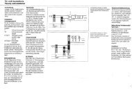
Door station mounting<br />
1 Unscrew the front of the housing.<br />
To do this, release the Allen key<br />
on the underneath of the housing.<br />
Hinge the front of the housing<br />
forward.<br />
2 Surface mounting the door<br />
station. Recommended mounting<br />
height appr. 1.50 m /4.9 ft. to centre<br />
device. Please note: The cable is<br />
inserted in the lower area of the<br />
base plate!<br />
3 Strip back the installation cable<br />
close to the wall (appr. 10 mm)<br />
and insert the cores into the base<br />
plate. Fasten the base plate using 4<br />
screws. Close the two openings at<br />
the top using rubber stoppers. Install<br />
in accordance with the terminal<br />
diagram.<br />
4 The pick-up angle of the camera<br />
can be mechanically preadjusted on<br />
the vertical and horizontal by appr.<br />
30° depending on the mounting<br />
situation. To change the pick-up<br />
direction of the camera, it can be<br />
positioned in the required direction.<br />
To change the pick-up direction,<br />
loosen the two cross-head screws<br />
slightly. Position the camera in the<br />
required direction. Then fix the<br />
required position using the two<br />
cross-head screws.