Produkt- information Set-Compact-Video SET CV 850-1 bis ... - Siedle
Produkt- information Set-Compact-Video SET CV 850-1 bis ... - Siedle
Produkt- information Set-Compact-Video SET CV 850-1 bis ... - Siedle

Create successful ePaper yourself
Turn your PDF publications into a flip-book with our unique Google optimized e-Paper software.
5 Depending on the installation<br />
environment, it may be necessary<br />
to change the door station speech<br />
volume in order to permit clear<br />
speech transmission.<br />
6 Hook the front of the housing<br />
onto the base plate at the top and<br />
close. Tighten the Allen key on the<br />
underneath of the housing.<br />
Mounting the bus line rectifier<br />
7 Mount the line rectifier on the top<br />
hat rail (distribution).<br />
8 Surface mounting is possible with<br />
accessory ZAP 9-0. (not included in<br />
scope of supply)<br />
Mounting the bus telephone<br />
Strip back cable to appr. 80 mm.<br />
9 Open the device from the back by<br />
pressing in the locking lever.<br />
10 Recommended mounting height<br />
appr. 1.50 m /4.9 ft. to centre<br />
device.<br />
11 When mounting directly on the<br />
wall, fasten the base plate using<br />
4 screws, paying attention that<br />
the plate is the right way up (top<br />
marking).<br />
12 When mounting on a switch box,<br />
use the screw openings in the centre<br />
of the device, paying attention that<br />
the plate is the right way up (top<br />
marking).<br />
13 Install in accordance with the<br />
wiring diagram. The cores of the<br />
installation cable must be stored<br />
inside the free installation space in<br />
the base plate.<br />
14 Insert the coloured plug of the<br />
spiral cable into the socket at the<br />
housing. A distinct click is audible<br />
when the plug is correctly inserted.<br />
15 Insert the other end of the spiral<br />
cable in the receiver until the plug<br />
clicks audibly into place.<br />
This connection can no longer be<br />
detached.<br />
16 With plug+play programming<br />
do not close the housing until<br />
programming is under way. Hook<br />
the housing into the base plate from<br />
above and close by exerting a slight<br />
pressure.<br />
Removing the in-house telephone<br />
17 To remove the housing, press<br />
the lock upwards using a flat blade<br />
screwdriver. The circuit board and<br />
receiver remain on the upper part of<br />
the housing.<br />
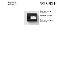
Lettering<br />
18 Open the name plate from the<br />
outside, for example using a flat<br />
bladed screwdriver, and carefully<br />
remove the name plate. To insert<br />
the name plate, lock into place by<br />
exerting light pressure.<br />
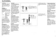
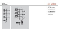
Installation<br />
Connect in accordance with the<br />
wiring diagram AS-TVHa-1/1.<br />
Terminal diagram for 125 V version<br />
TÖ = door release<br />
ERT = Storey call button<br />
Li = Light<br />
Range from video set line rectifier to<br />
door station max. 50 m/164 ft, video<br />
set line rectifier to the most distant<br />
bus telephone 50 m/164 ft with<br />
0.8 mm conductor material. Following<br />
completed installation, the<br />
video set must be programmed.<br />
Terminal assignment<br />
TaK/TbK In-Home bus: Terminal<br />
to the video set line rectifier<br />
VSNG <strong>850</strong>-...<br />
Specifications <strong>CV</strong> <strong>850</strong>-...<br />
• Colour system PAL<br />
• Image pick-up CCD-Sensor 1/3”<br />
752 x 582 pixel (horizontal/vertical)<br />
• Lens 3.7 mm<br />
• Pick-up angle horizontal appr. 60°,<br />
vertical appr. 50°<br />
• Additional mechanical adjustment<br />
range by around 30° horizontally<br />
and vertically<br />
• Horizontal resolution 450 lines<br />
• Integrated infrared lighting<br />
• Temperature range<br />
-20°C to + 40°C<br />
• Supply via In-Home bus: <strong>Video</strong><br />
• Door loudspeaker protection<br />
system IP 54<br />
• Dimensions 82 x 226 x 39 mm<br />
Specifications VSNG <strong>850</strong>-0<br />
• Input voltage 230 V AC +/-10%,<br />
50-60 Hz<br />
• Primary fuse 250 mA (L) 250 V<br />
• Current consumption 200 mA<br />
• Bus voltage 27.5 V DC 0.5 A stabilized<br />
+/- 5%, short circuit proof at<br />
terminals TaK/TbK and TaM/TbM<br />
• 12 V AC, 1 A<br />
• Ambient temperature<br />
0°C to +40°C, operation at an<br />
altitude between -20 and 2000 m<br />
above sea level<br />
• Max. relative humidity 60%<br />
• Protection system IP 30<br />
• Dimensions 162 x 89 x 60 mm<br />
Specifications VSNG <strong>850</strong>-1<br />
• Input voltage 125 V AC +/-10%,<br />
50-60 Hz<br />
• Primary fuse 500 mA (L) 250 V<br />
• Current consumption 360 mA<br />
• For other specifications, see above<br />
Specifications<br />
• Supply via in-home bus<br />
• Ring tone volume: max. 83 dB (A)<br />
• Colour monitor 6.3 cm (2.5 „)<br />
• Current consumption on supply via<br />
+M/-M max. 300 mA<br />
• Potential-free contact S1/S1 max.<br />
15 V AC, 30V DC, 1A Switching<br />
time 0.4 secs. - 19 mins.<br />
• Dimensions W x H x D<br />
90 x 261 x 45 mm (BTSV <strong>850</strong>-...)<br />
• Dimensions W x H x D<br />
90 x 261 x 27 mm (BFSV <strong>850</strong>-...)<br />
15