SIMATIC PCS 7 Process Control System - Siemens
SIMATIC PCS 7 Process Control System - Siemens
SIMATIC PCS 7 Process Control System - Siemens

You also want an ePaper? Increase the reach of your titles
YUMPU automatically turns print PDFs into web optimized ePapers that Google loves.
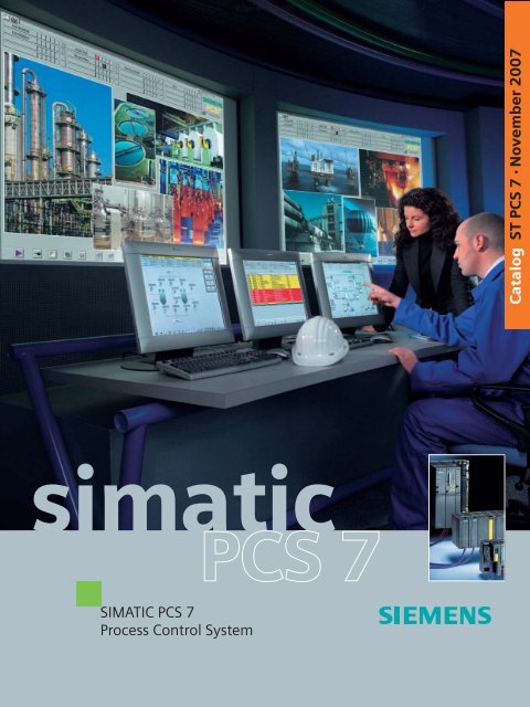
simatic<br />
<strong>SIMATIC</strong> <strong>PCS</strong> 7<br />
<strong>Process</strong> <strong>Control</strong> <strong>System</strong><br />
© <strong>Siemens</strong> AG 2007<br />
Catalog ST <strong>PCS</strong> 7 · November 2007
Related catalogs<br />
<strong>SIMATIC</strong><br />
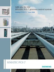
Add-ons for the <strong>SIMATIC</strong> <strong>PCS</strong> 7<br />
<strong>Process</strong> <strong>Control</strong> <strong>System</strong><br />
Only PDF:<br />
(E86060-K4678-A121-A6-7600)<br />
<strong>SIMATIC</strong><br />
Migration solutions with the<br />
<strong>SIMATIC</strong> <strong>PCS</strong> 7<br />
<strong>Process</strong> <strong>Control</strong> <strong>System</strong><br />
Order no.:<br />
E86060-K4678-A131-A3-7600<br />
ST <strong>PCS</strong> 7.1<br />
ST <strong>PCS</strong> 7.2<br />
<strong>SIMATIC</strong><br />
ST 70<br />
Products for Totally Integrated<br />
Automation and Micro Automation<br />
Order no.:<br />
E86060-K4670-A101-B1-7600<br />
E86060-K4670-A151-A3-7600 (News)<br />
<strong>SIMATIC</strong> HMI<br />
Human Machine Interface<br />
<strong>System</strong>s<br />
Order no.:<br />
E86060-K4680-A101-B5-7600<br />
ST 80<br />
Industrial Communication IK PI<br />
Industrial Communication for<br />
Automation and Drives<br />
Order no.:<br />
E86060-K6710-A101-B5-7600<br />
E86060-K6710-A121-A2-7600 (News)<br />
TELEPERM M<br />
AS 488/TM<br />
Automation <strong>System</strong>s<br />
Only PDF:<br />
(E86060-W3812-A100-A3-7600)<br />
Field Instruments<br />
for <strong>Process</strong> Automation<br />
Order no.:<br />
E86060-K6201-A101-A9-7600<br />
PLT 112<br />
FI 01<br />
© <strong>Siemens</strong> AG 2007<br />
Training for Automation and ITC<br />
Industrial Solutions<br />
Order no.:<br />
E86060-K6850-E101-B8 (in German)<br />
Catalog CA 01<br />
the Offline Mall of<br />
Automation and Drives<br />
Order no.:<br />
E86060-D4001-A100-C6 (CD-ROM)<br />
E86060-D4001-A500-C6 (DVD)<br />
A&D Mall<br />
Internet:<br />
www.siemens.com/automation/mall<br />
I<br />
T<br />
C
<strong>SIMATIC</strong> <strong>PCS</strong> 7<br />
<strong>Process</strong> <strong>Control</strong> <strong>System</strong><br />
Version 7.0<br />
Catalog ST <strong>PCS</strong> 7 ·<br />
October 2007<br />
Supersedes:<br />
Catalog ST <strong>PCS</strong> 7 · March 2007<br />
The products contained in this catalog<br />
can also be found in the e-Catalog CA 01<br />
Order No.:<br />
E86060-D4001-A110-C6-7600 (CD-ROM)<br />
E86060-D4001-A510-C6-7600 (DVD)<br />
Please contact<br />
your local<br />
<strong>Siemens</strong> branch<br />
© <strong>Siemens</strong> AG 2007<br />
The products and systems<br />
described in this<br />
catalog are manufactured/distributed<br />
under<br />
application of a certified<br />
quality management<br />
system in accordance<br />
with DIN EN ISO 9001<br />
(Certified Registration<br />
No. 1323-QM). The certificate<br />
is recognized by<br />
all IQNet countries.<br />
s<br />
© <strong>Siemens</strong> AG 2007<br />
Introduction<br />
<strong>System</strong>-neutral components<br />
Starter systems<br />
Engineering system<br />
Operator system<br />
Batch automation<br />
<strong>SIMATIC</strong> Route <strong>Control</strong><br />
Asset Management<br />
Communication<br />
Automation systems<br />
<strong>Process</strong> I/O<br />
IT world<br />
Migration to <strong>SIMATIC</strong> <strong>PCS</strong> 7<br />
1<br />
2<br />
3<br />
4<br />
5<br />
6<br />
7<br />
8<br />
9<br />
10<br />
11<br />
12<br />
13<br />
Ordering data for previous version<br />
<strong>SIMATIC</strong> <strong>PCS</strong> 7 V6.1 14<br />
Update/upgrade packages<br />
Appendix<br />
15<br />
16
1/2<br />
<strong>Siemens</strong> ST <strong>PCS</strong> 7 · November 2007<br />
© <strong>Siemens</strong> AG 2007<br />
<strong>Siemens</strong> Automation and Drives.<br />
Welcome<br />
More than 70,000 people aiming for the same goal:<br />
increasing your competitiveness. That's <strong>Siemens</strong><br />
Automation and Drives.<br />
We offer you a comprehensive portfolio for sustained<br />
success in your sector, whether you're talking automation<br />
engineering, drives or electrical installation systems.<br />
Totally Integrated Automation (TIA) and Totally<br />
Integrated Power (TIP) form the core of our offering.<br />
TIA and TIP are the basis of our integrated range of<br />
products and systems for the manufacturing and process<br />
industries as well as building automation. This portfolio<br />
is rounded off by innovative services over the entire life<br />
cycle of your plants.<br />
Learn for yourself the potential our products and<br />
systems offer. And discover how you can permanently<br />
increase your productivity with us.<br />
Your regional <strong>Siemens</strong> contact can provide more information.<br />
He or she will be glad to help.
© <strong>Siemens</strong> AG 2007<br />
<strong>Siemens</strong> ST <strong>PCS</strong> 7 · November 2007<br />
1/3
Management Level<br />
Operations Level<br />
<strong>Control</strong> Level<br />
Field Level<br />
Totally<br />
Integrated<br />
Automation<br />
1/4<br />
ERP – Enterprise Resource Planning<br />
Ethernet<br />
MES – Manufacturing Execution <strong>System</strong>s<br />
Ethernet<br />
<strong>SIMATIC</strong> <strong>PCS</strong> 7<br />
<strong>Process</strong> <strong>Control</strong> (DCS)<br />
PROFINET<br />
Industrial Ethernet<br />
PROFIBUS<br />
<strong>Siemens</strong> ST <strong>PCS</strong> 7 · November 2007<br />
© <strong>Siemens</strong> AG 2007<br />
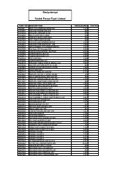
Sharpen your competitive edge.<br />
Totally Integrated Automation<br />
With Totally Integrated Automation (TIA), <strong>Siemens</strong> is the only<br />
manufacturer to offer an integrated range of products and systems<br />
for automation in all sectors - from incoming goods to outgoing<br />
goods, from the field level through the production control<br />
level to connection with the corporate management level.<br />
On the basis of TIA, we implement solutions that are perfectly<br />
tailored to your specific requirements and are characterized by a<br />
unique level of integration. This integration not only ensures significant<br />
reductions in interface costs but also guarantees the<br />
highest level of transparency across all levels.<br />
PROFIBUS PA<br />
HART<br />
Industrial Software for<br />
• Design and Engineering<br />
• Installation and Commissioning<br />
• Operation<br />
SINUMERIK<br />
Computer Numeric <strong>Control</strong><br />
<strong>Process</strong> Instrumentation<br />
• Maintenance<br />
• Modernization<br />
and Upgrade<br />
SIMOTION<br />
Motion <strong>Control</strong> <strong>System</strong><br />
<strong>SIMATIC</strong> Sensors<br />
AS-Interface
<strong>SIMATIC</strong> IT<br />
<strong>SIMATIC</strong> NET<br />
Industrial<br />
Communication<br />
<strong>SIMATIC</strong> <strong>Control</strong>lers<br />
Modular/Embedded/PC-based<br />
<strong>SIMATIC</strong> Distributed I/O<br />
<strong>SIMATIC</strong> WinCC<br />
SCADA <strong>System</strong><br />
<strong>SIMATIC</strong> HMI<br />
Human Machine Interface<br />
SINAMICS Drive <strong>System</strong>s<br />
© <strong>Siemens</strong> AG 2007<br />
It goes without saying that you profit from Totally Integrated<br />
Automation during the entire life cycle of your plants - from the<br />
first planning steps, through operation, right up to modernization.<br />
Consistent integration in the further development of our<br />
products and systems guarantees a high degree of investment<br />
security here.<br />
Totally Integrated Automation makes a crucial contribution<br />
towards optimizing everything that happens in the plant and<br />
thus creates the conditions for a significant increase in productivity.<br />
Safety Integrated<br />
SIRIUS Industrial <strong>Control</strong>s<br />
SENTRON Switching Devices<br />
SIMOCODE pro<br />
Motor Management <strong>System</strong><br />
<strong>Siemens</strong> ST <strong>PCS</strong> 7 · November 2007<br />
AS-Interface<br />
Totally<br />
Integrated<br />
Power<br />
KNX/EIB<br />
GAMMA instabus<br />
1/5
1/6<br />
<strong>Siemens</strong> ST <strong>PCS</strong> 7 · November 2007<br />
Communication<br />
<strong>Process</strong>/production<br />
automation<br />
Products and systems<br />
Planning<br />
and configuration<br />
© <strong>Siemens</strong> AG 2007<br />
Integrated energy distribution from a single source.<br />
Totally Integrated Power<br />
Totally Integrated Power (TIP) brings together all the components<br />
of electrical energy distribution into an integrated whole. Thus TIP<br />
provides the answer to growing market demands in the planning,<br />
construction and use of utility buildings and industrial buildings.<br />
On the basis of TIP, we offer integrated solutions for energy distribution,<br />
from medium voltage to the power outlet. Totally Integrated<br />
Power is based here on integration in planning and configuring<br />
as well as on perfectly matched products and systems.<br />
PROCESS FIELD BUS<br />
HMI Load Load<br />
Graphs Prognoses Prognoses<br />
management<br />
U<br />
UI<br />
I cos o<br />
cos P o<br />
PW<br />
W<br />
£ 110 kV
Maintenance<br />
Substation<br />
Distribution<br />
Distribution<br />
Maintenance<br />
task<br />
Hall 1 Air conditioning conditioning system<br />
checkup<br />
Distribution 3 Replacing circuit circuit<br />
breaker breaker contacts<br />
Infeed II Replacing meters<br />
Message/ Message/<br />
error<br />
management<br />
Selective<br />
protection<br />
Protocols Power<br />
quality<br />
DATE:<br />
EMPLOYEE<br />
COST CENTER<br />
PAY PERIOD BEGINNING<br />
PAY PERIOD ENDING<br />
DATE<br />
SUN MON TUE WED THUR FRI SAT SUN TOTAL<br />
IN<br />
OUT<br />
IN<br />
OUT<br />
OVERTIME<br />
TOTAL HOURS<br />
DATE<br />
SUN MON TUE WED THUR FRI SAT SUN TOTAL<br />
IN<br />
OUT<br />
IN<br />
OUT<br />
OVERTIME<br />
TOTAL HOURS<br />
DATE<br />
SUN MON TUE WED THUR FRI SAT SUN TOTAL<br />
IN<br />
OUT<br />
IN<br />
OUT<br />
OVERTIME<br />
TOTAL HOURS<br />
CODES<br />
V=VACATION<br />
H=HOLIDAY<br />
S=SICK<br />
REGULAR HOLIDAY OTHER<br />
OVER THE HOURS<br />
SICK VACATION<br />
TIME & ONE-HALF<br />
© <strong>Siemens</strong> AG 2007<br />
Totally Integrated Power offers communication<br />
and software modules for connecting the energy<br />
distribution systems to industrial automation and<br />
building automation. This enables the implementation<br />
of significant savings potential.<br />
Cost center<br />
instabus EIB<br />
Building<br />
automation<br />
<strong>Siemens</strong> ST <strong>PCS</strong> 7 · November 2007<br />
1/7
1/8<br />
<strong>Siemens</strong> ST <strong>PCS</strong> 7 · November 2007<br />
© <strong>Siemens</strong> AG 2007<br />
Protecting the environment<br />
and resources.<br />
Environmental sustainability<br />
Environmental protection will continue to grow in importance<br />
as a result of progressive urbanization and global population<br />
growth. These global mega-trends make the careful and sustainable<br />
handling of natural resources a central challenge.<br />
We are convinced that every individual - and especially<br />
every company - has an ecological responsibility. At <strong>Siemens</strong><br />
Automation and Drives, we stand by this conviction. Our high<br />
environmental protection goals are part of our strict environmental<br />
management. We investigate the possible effects of our<br />
products and systems on the environment right back at the development<br />
stage. We concern ourselves, for example, with the<br />
question of how to reduce power consumption in plant<br />
operation - and we offer appropriate solutions, such as our<br />
energy-saving motors that cut power consumption in industrial<br />
manufacturing by up to 40% thanks to their high efficiency<br />
levels.<br />
Our products and systems comply with the EC Directive<br />
RoHS (Restriction of Hazardous Substances). All the relevant<br />
<strong>Siemens</strong> AG sites are, of course, certified in accordance with<br />
DIN EN ISO 14001.<br />
Our commitment goes well beyond compliance with the relevant<br />
directives and legislation: we are an active driving force<br />
behind environmental protection, through further development<br />
of environmental management systems, for example,<br />
and we are involved in professional associations such as the<br />
German Electrical and Electronic Manufacturers Association<br />
(ZVEI).
© <strong>Siemens</strong> AG 2007<br />
<strong>Siemens</strong> ST <strong>PCS</strong> 7 · November 2007<br />
1/9
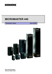
Introduction<br />
<strong>System</strong> architecture<br />
<strong>SIMATIC</strong> <strong>PCS</strong> 7 V7.0<br />
■ Overview<br />
<strong>SIMATIC</strong> <strong>PCS</strong> 7<br />
Takes you beyond the limits!<br />
<strong>SIMATIC</strong><br />
<strong>PCS</strong> 7 BOX<br />
<strong>SIMATIC</strong> <strong>PCS</strong> 7 system configuration<br />
Totally Integrated Automation with <strong>SIMATIC</strong> <strong>PCS</strong> 7<br />
The <strong>SIMATIC</strong> <strong>PCS</strong> 7 process control system is a significant component<br />
of Totally Integrated Automation (TIA), the unique basis<br />
offered by <strong>Siemens</strong> for uniform and customized automation in all<br />
sectors of the production, process and hybrid industries. Using<br />
TIA, <strong>Siemens</strong> is the only company able to offer uniform automation<br />
technology on one single platform for all applications of process<br />
automation, starting with input logistics, covering production<br />
or primary processes as well as downstream (secondary)<br />
processes, up to output logistics. This is suitable for optimization<br />
of all operating sequences of an entire company, i.e. from the<br />
ERP (Enterprise Resource Planning) level and MES (Management<br />
Execution <strong>System</strong>) level to the control level, right down to<br />
the field level.<br />
Integrated in a holistic automation solution for a production site,<br />
automation of the primary processes is the prime task of SI-<br />
MATIC <strong>PCS</strong> 7. On the other hand, secondary processes (e.g. filling,<br />
packaging) or input/output logistics (e.g. raw material distribution,<br />
storage) are frequently implemented using the PLCbased<br />
or PC-based components of <strong>SIMATIC</strong>.<br />
The advantages of Totally Integrated Automation, in particular<br />
the uniform data management, communication and configuration,<br />
are already evident during planning and engineering, but<br />
also during installation and commissioning, everyday operation<br />
as well as maintenance, repairs and modernization.<br />
1/10<br />
ET 200M<br />
FF-H1<br />
ET 200M<br />
with CP 341<br />
OS<br />
Single Station<br />
<strong>SIMATIC</strong><br />
<strong>PCS</strong> 7<br />
AS RTX<br />
DP/FF Link<br />
DP/AS-Interface link<br />
Modbus, serial connection<br />
Integrated Drives<br />
PROFIBUS DP<br />
OS / Route <strong>Control</strong><br />
Server<br />
Standard<br />
automation<br />
systems<br />
Zone 2<br />
Ex I/O, HART<br />
<strong>Siemens</strong> ST <strong>PCS</strong> 7 · November 2007<br />
INTERNET<br />
OS / Batch / Route <strong>Control</strong><br />
Clients<br />
ET 200M<br />
ET 200M<br />
DP/PA link<br />
PROFIBUS DP<br />
OS-LAN, single/redundant<br />
Weighing systems<br />
ET 200S<br />
Zone 1<br />
ET 200iSP<br />
HART<br />
© <strong>Siemens</strong> AG 2007<br />
PROFIBUS PA<br />
Office LAN (Ethernet)<br />
Industrial Ethernet, single/redundant<br />
Ex operator<br />
terminal<br />
Web Client<br />
PROFIBUS DP<br />
Security<br />
Modules<br />
MTA<br />
SAP<br />
DP/PA link<br />
INTERNET<br />
Fault-tolerant<br />
automation<br />
systems<br />
DP/PA link<br />
Y link<br />
Web Server/<br />
Open<strong>PCS</strong> 7<br />
Ethernet<br />
Batch/archive<br />
server<br />
ET 200M<br />
single/redundant<br />
ET 200iSP<br />
Network<br />
printer<br />
PROFIBUS PA<br />
COx, NO x<br />
PROFIBUS PA<br />
Active Field Distributors<br />
Management information/<br />
Manufacturing Execution <strong>System</strong><br />
Engineering<br />
Station<br />
Uniform data management means that all software components<br />
access a common database. Within a project, inputs and modifications<br />
are therefore only necessary at one point. This reduces<br />
the work required, and simultaneously avoids potential faults.<br />
Once symbolic identifications have been introduced, they are<br />
understood by every software component. Data consistency is<br />
also guaranteed even if several persons are working simultaneously<br />
on a project. Parameters defined in the engineering system<br />
can be transferred beyond the network limits down to sensors,<br />
actuators or drives in the field.<br />
Uniform communication from the corporate management level<br />
down to the field level is based on internationally recognized<br />
standards such as Industrial Ethernet or PROFIBUS, and also<br />
supports the global flow of information via the Internet. Since the<br />
hardware and software components involved also use these<br />
communications mechanisms, connections are extremely easy<br />
to configure, also cross-system or over different networks.<br />
The use of an engineering system with a uniform and matched<br />
range of tools minimizes the configuration overhead. The engineering<br />
tools for the application software, the hardware components<br />
and the communications functions can be called from a<br />
central project manager (<strong>SIMATIC</strong> Manager). This is also the basic<br />
application for creation, management, saving and documentation<br />
of a project.<br />
Compatibility of further developments is guaranteed within TIA.<br />
This also guarantees that the company’s investments have a secure<br />
future, and allows the company to modernize and expand<br />
the plants throughout the complete lifecycle.<br />
PROFIBUS DP<br />
<strong>SIMATIC</strong> IT<br />
Asset Management/<br />
Maintenance station<br />
Safety-related<br />
automation<br />
systems<br />
ET 200M<br />
Standard and<br />
F modules<br />
ET 200M<br />
F modules<br />
DP/PA link<br />
with redundant<br />
DP/PA couplers<br />
Active Field Splitter<br />
PROFIBUS PA<br />
ET 200pro<br />
ET 200S
■ Benefits<br />
With its pioneering design, modular and open architecture<br />
based on state-of-the-art <strong>SIMATIC</strong> technology, consistent application<br />
of industrial standards, and the I&C functionality paired<br />
with high-performance, the <strong>SIMATIC</strong> <strong>PCS</strong> 7 process control system<br />
allows cost-effective implementation and economical operation<br />
of I&C plants in all phases of their lifecycle and with consideration<br />
of all aspects: from planning, engineering,<br />
commissioning, training, through operation, maintenance and<br />
repair, up to expansion and refurbishment. In the process, SI-<br />
MATIC <strong>PCS</strong> 7 combines high-performance and reliability with<br />
simple and safe operation and maximum convenience.<br />
You primarily profit from Totally Integrated Automation with the<br />
<strong>SIMATIC</strong> <strong>PCS</strong> 7 process control system through:<br />
7 Calculable development, implementation and lifecycle costs<br />
7 Minimization of engineering overhead<br />
7 Facilities for process optimization<br />
7 Adaptability to changing requirements<br />
7 Advantages resulting from the use of standard <strong>SIMATIC</strong> components,<br />
such as:<br />
- Low hardware and engineering costs<br />
- Proven quality and stability<br />
- Simple, fast definition and selection of system components<br />
- Low costs for spare parts<br />
- Short delivery times for spare parts and expansion components<br />
- Global availability<br />
- Savings in logistics, maintenance and training costs<br />
■ Function<br />
A consistent and homogeneous overall system<br />
<strong>SIMATIC</strong> <strong>PCS</strong> 7 is a modern process control system that can be<br />
used alone or in combination with other systems, e.g. <strong>SIMATIC</strong>,<br />
SIMOTION or drive systems, as a consistent and homogenous<br />
overall system. Its popularity is increasing along with the demand<br />
for seamlessly integrated universal automation engineering<br />
solutions, which is determined by sustained competition and<br />
price pressure, the demand for increasingly flexible production<br />
plants and the need for increased productivity.<br />
Against the background of ever-increasing complexity, in particular<br />
due to the merging of automation engineering with information<br />
technology, horizontal and vertical integrated system platforms<br />
are being increasingly accepted in comparison to<br />
automation solutions with so-called "best-in-class products".<br />
Totally Integrated Automation with <strong>SIMATIC</strong> <strong>PCS</strong> 7 combines<br />
consistent data management, communication and configuration<br />
with outstanding system properties and high performance. This<br />
guarantees that the typical demands placed on a process control<br />
system are comprehensively satisfied, and that you are perfectly<br />
equipped for future requirements:<br />
7 Simple and reliable process control<br />
7 User-friendly operation and visualization, also using the<br />
Internet<br />
7 Powerful, fast and consistent system-wide engineering<br />
7 <strong>System</strong>-wide online modifications<br />
7 <strong>System</strong> openness at all levels<br />
7 Flexibility and scalability<br />
7 Redundancy at all levels<br />
7 Safety-related automation solutions<br />
7 Extensive fieldbus integration<br />
7 Flexible solutions for batch processes<br />
© <strong>Siemens</strong> AG 2007<br />
Introduction<br />
<strong>System</strong> architecture<br />
<strong>SIMATIC</strong> <strong>PCS</strong> 7 V7.0<br />
7 Efficient control of material transport<br />
7 Asset management for I&C equipment (diagnostics, preventive<br />
maintenance and repairs)<br />
7 Direct interface with the IT world<br />
7 Advanced security concept for safeguarding the I&C system.<br />
Flexibility and scalability<br />
As a result of its modular architecture based on selected hardware<br />
and software components from the standard <strong>SIMATIC</strong><br />
range, <strong>SIMATIC</strong> <strong>PCS</strong> 7 can be applied effectively in small and<br />
large plants alike. It allows easy expansion or system modification<br />
to enable customers to meet the changing production requirements<br />
of their facility. <strong>SIMATIC</strong> <strong>PCS</strong> 7 is scalable from a<br />
small single system consisting of approx. 160 process tags (motors,<br />
valves, PID controllers), such as might be used for a laboratory<br />
system or a test center, up to a distributed multi-user system<br />
with client/server architecture and approx. 60,000 process<br />
tags, such as might be used for automation of a very large production<br />
plant or for groups of connected facilities.<br />
<strong>SIMATIC</strong> <strong>PCS</strong> 7 thus covers all sizes of plant - and if the plant<br />
grows, <strong>SIMATIC</strong> <strong>PCS</strong> 7 grows with it!<br />
Open for the future<br />
<strong>SIMATIC</strong> <strong>PCS</strong> 7 is based on modular hardware and software<br />
components, which are perfectly matched to one another due to<br />
their conformance with TIA. These components can be expanded<br />
and innovated seamlessly and with little effort and are<br />
open for the future via long-term stable interfaces. This makes<br />
long-term protection of customer investments possible, despite<br />
the fast pace of innovation and short product cycles.<br />
<strong>SIMATIC</strong> <strong>PCS</strong> 7 consistently applies new, powerful technologies<br />
together with internationally established industrial standards<br />
such as IEC, XML, PROFIBUS, Ethernet Gigabit technology,<br />
TCP/IP, OPC, ISA-88 or ISA-95, just to mention a few.<br />
Openness with <strong>SIMATIC</strong> <strong>PCS</strong> 7 covers all levels, and equally applies<br />
to automation systems and process I/Os as to industrial<br />
communications networks, operator systems or engineering<br />
systems.<br />
Not just system architecture and communication are characterized<br />
by openness. This is a feature also evident in the programming<br />
and data transfer interfaces for user programs as well as in<br />
the import and export functions for graphics, text and data, e.g.<br />
from the CAD/CAE world. <strong>SIMATIC</strong> <strong>PCS</strong> 7 can therefore also be<br />
combined with components from other vendors, and integrated<br />
in existing infrastructures.<br />
<strong>Siemens</strong> ST <strong>PCS</strong> 7 · November 2007<br />
1/11
1/12<br />
Introduction<br />
<strong>Siemens</strong> ST <strong>PCS</strong> 7 · November 2007<br />
© <strong>Siemens</strong> AG 2007
© <strong>Siemens</strong> AG 2007<br />
<strong>System</strong>-neutral<br />
components<br />
2/2 <strong>System</strong> documentation<br />
2/4 Administration<br />
2/6 Operating system<br />
2/7 <strong>SIMATIC</strong> <strong>PCS</strong> 7 Industrial<br />
Workstation<br />
2/7 Introduction<br />
2/10 Basic hardware<br />
2/16 Multi-VGA graphics cards<br />
2/17 Operator panels/monitors<br />
2/18 Special configurations<br />
<strong>Siemens</strong> ST <strong>PCS</strong> 7 · November 2007
<strong>System</strong>-neutral components<br />
2 <strong>System</strong> documentation<br />
■ Overview<br />
The system documentation of the <strong>SIMATIC</strong> <strong>PCS</strong> 7 process control<br />
system is an integral component of the <strong>SIMATIC</strong> <strong>PCS</strong> 7 system<br />
software. It is available in two versions:<br />
• As online help (HTML help)<br />
• As electronic documentation in Acrobat Reader format (PDF)<br />
The 3-language documentation (German, English, French) provides<br />
both beginners and experienced users with valuable information<br />
on all aspects of the process control system. The range<br />
extends from the system introduction, covers initial steps and<br />
cross-system topics, up to a description of individual system<br />
components. With the "Getting Started" documentation you can<br />
gain initial practical experience using example projects.<br />
<strong>SIMATIC</strong> <strong>PCS</strong> 7 Programming Instructions Driver Blocks<br />
Programming Instructions for creating drive blocks and with the<br />
title "<strong>SIMATIC</strong> <strong>PCS</strong> 7 Programming Instructions Driver Blocks"<br />
can be ordered separately. These Programming Instructions<br />
help the advanced <strong>SIMATIC</strong> <strong>PCS</strong> 7 user to create system-conform<br />
driver blocks, which can be placed like standard blocks on<br />
system plans and automatically parameterized and interconnected<br />
in HW-Config.<br />
2/2<br />
<strong>Siemens</strong> ST <strong>PCS</strong> 7 · November 2007<br />
© <strong>Siemens</strong> AG 2007<br />
S7 Manual Collection<br />
As a supplement to the <strong>SIMATIC</strong> <strong>PCS</strong> 7 system documentation,<br />
the S7 Manual Collection provides comprehensive information<br />
on all system components offered in the context of <strong>SIMATIC</strong> S7.<br />
This multi-language collection of electronic manuals on DVD<br />
contains documentation on the following in addition to the<br />
<strong>SIMATIC</strong> <strong>PCS</strong> 7 system documentation:<br />
• <strong>SIMATIC</strong> S7-200/300/400,<br />
• <strong>SIMATIC</strong> C7,<br />
• LOGO! logic module,<br />
• <strong>SIMATIC</strong> DP,<br />
• <strong>SIMATIC</strong> PC,<br />
• <strong>SIMATIC</strong> programming devices,<br />
• STEP 7,<br />
• engineering software,<br />
• runtime software,<br />
• <strong>SIMATIC</strong> <strong>PCS</strong> 7,<br />
• <strong>SIMATIC</strong> HMI and<br />
• <strong>SIMATIC</strong> NET.<br />
The electronic manuals of the S7 Manual Collection are usually<br />
in 5 languages (German, English, French, Italian, Spanish),<br />
those of the integral <strong>SIMATIC</strong> <strong>PCS</strong> 7 system documentation<br />
mostly in 3 languages (German, English, French).<br />
For the migration of existing plants, you may also require detailed<br />
information on the system components of TELEPERM M or<br />
<strong>SIMATIC</strong> S5.<br />
TELEPERM M Manual Collection<br />
The TELEPERM M Manual Collection comprises TELEPERM M<br />
manuals in 2 languages (German, English) on CD.<br />
S5 Manual Collection<br />
An S5 Manual Collection in 2 languages (German, English) on<br />
CD, which contains all electronic manuals concerning<br />
<strong>SIMATIC</strong> S5, rounds off the range of available information.
■ Selection and Ordering Data Order No ■ More information<br />
<strong>SIMATIC</strong> <strong>PCS</strong> 7 Programming<br />
Instructions Driver Blocks V7.0<br />
for <strong>SIMATIC</strong> <strong>PCS</strong> 7 V6.1 and V7.0<br />
Electronic documentation on CD,<br />
in 2 languages (German, English)<br />
Type of delivery: CD, certificate of<br />
license, terms and conditions<br />
<strong>SIMATIC</strong> S7 manuals<br />
6ES7 653-1XD07-8YX8<br />
S7 Manual Collection<br />
Electronic manuals on DVD, in<br />
5 languages (German, English,<br />
French, Italian, Spanish)<br />
6ES7 998-8XC01-8YE0 D)<br />
S7 Manual Collection -<br />
maintenance service for 1 year<br />
Type of delivery: Current DVD<br />
"S7 Manual Collection" and the<br />
three subsequent updates<br />
TELEPERM M migration manuals<br />
6ES7 998-8XC01-8YE2 D)<br />
TELEPERM M Manual<br />
Collection<br />
Electronic manuals on CD, in<br />
2 languages (German, English)<br />
<strong>SIMATIC</strong> S5 manuals<br />
6DL5 900-8AX03-8YX8 D)<br />
S5 Manual Collection<br />
Electronic manuals on CD, in<br />
2 languages (German, English)<br />
6ES5 998-7WE02 D)<br />
D) Subject to export regulations: AL: N, ECCN: 5D992B1<br />
© <strong>Siemens</strong> AG 2007<br />
<strong>System</strong>-neutral components<br />
<strong>System</strong> documentation<br />
The "<strong>SIMATIC</strong> Guide Manuals" on the Internet directs you<br />
straight to the complete range of technical documentation available<br />
for <strong>SIMATIC</strong> products and systems in German, English,<br />
French, Italian, Spanish and Chinese. If other languages are<br />
available, you can also find them there. You can select individual<br />
documents from this range for viewing or downloading.<br />
Additional information is available in the Internet under:<br />
http://www.siemens.com/simatic-docu<br />
<strong>Siemens</strong> ST <strong>PCS</strong> 7 · November 2007<br />
2/3<br />
2
2 Administration<br />
■ Overview<br />
2/4<br />
<strong>System</strong>-neutral components<br />
Central user management, access control and electronic<br />
signature<br />
<strong>SIMATIC</strong> Logon is a central user administration function with access<br />
control based on Windows 2000/XP and Windows Server<br />
2003 for:<br />
• <strong>System</strong> components of <strong>SIMATIC</strong> <strong>PCS</strong> 7<br />
• Non-system components linked via an interface<br />
It can be used to fulfill the validation requirements of 21 CFR Part<br />
11. An electronic signature function can also be used in conjunction<br />
with <strong>SIMATIC</strong> Logon.<br />
<strong>SIMATIC</strong> Logon Upgrade<br />
All previous versions can be upgraded to the current version.<br />
■ Design<br />
The optional chipcard reader can be used for access control in<br />
addition to the keyboard. <strong>SIMATIC</strong> Logon additionally supports<br />
logon devices which can be operated with a Microsoft device<br />
driver for the respective operating system (e.g. logon devices on<br />
a USB interface). It is also possible to connect logon devices via<br />
a separately created device-specific drive.<br />
The number of <strong>SIMATIC</strong> Logon licenses required depends on<br />
the number of clients/single stations that access applications for<br />
which <strong>SIMATIC</strong> Logon is used for access protection.<br />
<strong>SIMATIC</strong> Logon was developed for the <strong>SIMATIC</strong> <strong>PCS</strong> 7 process<br />
control system but can also be used together with other <strong>SIMATIC</strong><br />
products in the context of Totally Integrated Automation (TIA),<br />
e.g. with <strong>SIMATIC</strong> WinCC. A requirement for working together is<br />
that user groups have already been created in the partner applications,<br />
or can be defined.<br />
<strong>SIMATIC</strong> Logon is already integrated in the system software<br />
of the <strong>SIMATIC</strong> <strong>PCS</strong> 7 V7.0 process control system. Separate<br />
licenses are not required in this context.<br />
<strong>Siemens</strong> ST <strong>PCS</strong> 7 · November 2007<br />
© <strong>Siemens</strong> AG 2007<br />
■ Function<br />
<strong>SIMATIC</strong> Logon Admin Tool<br />
Using the <strong>SIMATIC</strong> Logon Admin Tool it is possible to assign the<br />
roles defined in the <strong>SIMATIC</strong> <strong>PCS</strong> 7 applications (e.g. Automation<br />
License Manager and <strong>SIMATIC</strong> BATCH) to the Windows<br />
users/user groups. Administrators with the necessary Windows<br />
administrator privileges can also use the <strong>SIMATIC</strong> Logon Admin<br />
Tool to edit Windows users and user groups.<br />
<strong>SIMATIC</strong> Logon Service<br />
The login dialog of the <strong>SIMATIC</strong> Logon Service is activated when<br />
an application is started which is managed by <strong>SIMATIC</strong> Logon.<br />
The user receives his specific privileges after making the login,<br />
password and domain entries. The <strong>SIMATIC</strong> Logon Service dialog<br />
for logoff, user change or password edit can be called in the<br />
applications.<br />
<strong>SIMATIC</strong> Electronic Signature<br />
The <strong>SIMATIC</strong> Electronic Signature means that operations cannot<br />
be performed until enabled by previously assigned Windows<br />
users/user groups. Users/user groups are assigned to the operations<br />
in the respective application.<br />
At the moment this function is implemented as a system function<br />
only on <strong>SIMATIC</strong> BATCH. However, the Electronic Signature can<br />
be used on any products in the specific applications.<br />
The software products listed here under "Selection and ordering<br />
data" are only relevant to use in the TIA environment.
■ Selection and Ordering Data<br />
only for TIA applications<br />
Order No.<br />
<strong>SIMATIC</strong> Logon V1.4<br />
Single license for 1 installation<br />
7 languages (German, English,<br />
French, Spanish, Italian, Chinese,<br />
Japanese), executes with<br />
Windows 2000 Professional SP4,<br />
Windows 2000 Server, Windows<br />
XP Professional SP2 or Windows<br />
Server 2003 SP1 and R2<br />
Engineering software and electronic<br />
documentation on CD<br />
Type of delivery: CD, license key<br />
disk, emergency key disk, certificate<br />
of license, terms and conditions<br />
6ES7 658-7BX41-2YA0<br />
<strong>SIMATIC</strong> Logon Upgrade to<br />
V1.4<br />
Single license for 1 installation<br />
7 languages (German, English,<br />
French, Spanish, Italian, Chinese,<br />
Japanese), executes with<br />
Windows 2000 Professional SP4,<br />
Windows 2000 Server, Windows<br />
XP Professional SP2 or Windows<br />
Server 2003 SP1 and R2<br />
Engineering software and electronic<br />
documentation on CD<br />
Type of delivery: CD, license key<br />
disk, emergency key disk, certificate<br />
of license, terms and conditions<br />
Options<br />
6ES7 658-7BX41-2YE0<br />
Chipcard reader USB<br />
Chipcard reader with USB interface,<br />
driver software and operating<br />
instructions<br />
6ES7 652-0XX02-1XC0 B)<br />
Chipcard<br />
Chipcard for chipcard reader;<br />
1 card required per user;<br />
package with 10 chipcards<br />
6ES7 652-0XX05-1XD1<br />
B) Subject to export regulations: AL: N, ECCN: EAR99H<br />
© <strong>Siemens</strong> AG 2007<br />
<strong>System</strong>-neutral components<br />
<strong>Siemens</strong> ST <strong>PCS</strong> 7 · November 2007<br />
Administration<br />
■ Options<br />
Access security by means of chipcard reader<br />
A chipcard reader can be used to check a person’s authorization<br />
to access and operate a single station or a client. This method of<br />
access security uses the chipcard as a "key" to the operator terminals.<br />
Operations are only allowed when the card is actually inserted<br />
in the reader.<br />
The unmistakable identification of access rights is required in<br />
particular for plants which have to meet validation requirements.<br />
The chipcard reader is compliant with EN 55022 Class B and<br />
EN 50082-1 standards.<br />
The reader is available with an USB interface for the connection<br />
of the operator station.<br />
Note:<br />
The reader with USB interface can only be used with <strong>SIMATIC</strong> Logon.<br />
2/5<br />
2
<strong>System</strong>-neutral components<br />
2 Operating system<br />
■ Overview<br />
Operating system upgrade<br />
When existing <strong>SIMATIC</strong> <strong>PCS</strong> 7 systems are updated to<br />
Version 7.0, it may also be necessary to upgrade the operating<br />
system.<br />
If you replace your existing hardware by new <strong>SIMATIC</strong> <strong>PCS</strong> 7<br />
Industrial Workstations from this catalog when carrying out an<br />
upgrade, the Windows XP Professional or Windows Server 2003<br />
operating systems including 5 CAL (Client Access Licenses) required<br />
for <strong>SIMATIC</strong> <strong>PCS</strong> 7 V7.0 are already included in the scope<br />
of delivery. You can also purchase individual operating systems<br />
or additional Client Access Licenses (CAL) from Fujitsu <strong>Siemens</strong><br />
Computers GmbH.<br />
Contact address for quotations and orders<br />
Fujitsu <strong>Siemens</strong> Computers GmbH<br />
Mr. Dominikus Besserer<br />
Phone: +49 821 804-2434<br />
Fax: +49 821 804-2972<br />
E-mail: dominikus.besserer@fujitsu-siemens.com<br />
2/6<br />
<strong>Siemens</strong> ST <strong>PCS</strong> 7 · November 2007<br />
© <strong>Siemens</strong> AG 2007<br />
Note:<br />
Please note when ordering that <strong>SIMATIC</strong> <strong>PCS</strong> 7 V7.0 is operated<br />
together with Windows XP Professional Service Pack 2 and<br />
Windows Server 2003 Service Pack 2.<br />
Release 2 of Windows Server 2003 has not been approved<br />
for <strong>SIMATIC</strong> <strong>PCS</strong> 7 V7.0.
© <strong>Siemens</strong> AG 2007<br />
<strong>System</strong>-neutral components<br />
<strong>SIMATIC</strong> <strong>PCS</strong> 7 Industrial Workstation<br />
<strong>Siemens</strong> ST <strong>PCS</strong> 7 · November 2007<br />
Introduction<br />
■ Overview<br />
■ Design<br />
Microsoft Windows operating system<br />
The multi-language Microsoft Windows XP Professional or<br />
Server 2003 operating system as well as the <strong>SIMATIC</strong> <strong>PCS</strong> 7<br />
system software for OS or ES/OS are preinstalled on the SI-<br />
MATIC <strong>PCS</strong> 7 Industrial Workstation. The Microsoft Server 2003<br />
operating system is supplied with 5 CALs (Client Access Licenses).<br />
You can purchase further CALs from Fujitsu <strong>Siemens</strong><br />
Computers GmbH (see page 2/6).<br />
Monitors and multi-VGA operation<br />
The core component of the <strong>SIMATIC</strong> <strong>PCS</strong> 7 Industrial Workstation<br />
is a <strong>SIMATIC</strong> industrial PC without keyboard or monitor. This<br />
basic hardware can be combined with the industrial LCD monitors<br />
recommended in the Section "HMI devices/monitors" for<br />
<strong>SIMATIC</strong> <strong>PCS</strong> 7 in the Catalog "PC-based Automation" to suit the<br />
operating environment and the customer’s requirements.<br />
Using a multi-VGA graphics card, the visualization of a project/<br />
subproject when engineering or a plant/unit in process operation<br />
can be divided among up to 4 process monitors per operator<br />
station with application of different views (see page 2/16).<br />
This is supported in the <strong>SIMATIC</strong> <strong>PCS</strong> 7 workstations designed<br />
as clients by additional hardware versions:<br />
• <strong>SIMATIC</strong> <strong>PCS</strong> 7 OS Client RACK PC 547B WXP with multi-<br />
VGA graphics card "2 Screens" and<br />
We offer a range of modern, powerful <strong>SIMATIC</strong> <strong>PCS</strong> 7 Industrial<br />
Workstations for the systems positioned in the <strong>SIMATIC</strong> <strong>PCS</strong> 7 • <strong>SIMATIC</strong> <strong>PCS</strong> 7 OS Client RACK PC 547B WXP with multisystem<br />
architecture above the controller level, e.g. for engineer- VGA graphics card "4 Screens"<br />
ing, operation and monitoring (also via Internet/intranet), batch<br />
Clients and single stations with a standard graphic interface<br />
control, route control, asset management or IT applications etc.<br />
module for controlling a process monitor can also be expanded<br />
These are optimized for use as single station, client or server,<br />
by a multi-VGA graphics card "2 Screens" or "4 Screens" (see<br />
and can be expanded specific to the system.<br />
page 2/16).<br />
2/7<br />
2
<strong>System</strong>-neutral components<br />
<strong>SIMATIC</strong> <strong>PCS</strong> 7 Industrial Workstation<br />
2 Introduction<br />
■ Options<br />
Notes on the use of other basic hardware and non-<strong>SIMATIC</strong> software<br />
<strong>Siemens</strong> guarantees the compatibility of hardware and software software components, the support provided for elimination<br />
for system configurations based on components in this catalog. thereof is not free of charge.<br />
The system test confirms that the system software of the<br />
The licenses for plant bus communication via Industrial Ethernet,<br />
<strong>SIMATIC</strong> <strong>PCS</strong> 7 process control system can be run on the i.e. for Basic Communication Ethernet (BCE) and CP 1613 com-<br />
<strong>SIMATIC</strong> <strong>PCS</strong> 7 Industrial Workstations offered in this catalog. munication are bound to the <strong>SIMATIC</strong> <strong>PCS</strong> 7 Industrial Worksta-<br />
Despite comprehensive tests, it cannot be excluded that the tions. Depending on the selected type of communication, the<br />
function of a <strong>SIMATIC</strong> <strong>PCS</strong> 7 system could be disturbed or inter- <strong>SIMATIC</strong> <strong>PCS</strong> 7 Industrial Workstations for single stations and<br />
fered with as a result of additional non-<strong>SIMATIC</strong> software, i.e. servers are delivered either with a BCE license or CP 1613 li-<br />
software which has not been explicitly approved for <strong>SIMATIC</strong> cense. If you are not using <strong>SIMATIC</strong> <strong>PCS</strong> 7 V7.0 on <strong>SIMATIC</strong><br />
<strong>PCS</strong> 7.<br />
<strong>PCS</strong> 7 Industrial Workstations, you additionally require a<br />
If you use hardware other than the basic hardware offered in this<br />
catalog, or additional non-<strong>SIMATIC</strong> software, this is at your own<br />
risk. If compatibility problems arise as a result of these hardware/<br />
<strong>SIMATIC</strong> <strong>PCS</strong> 7 BCE V7.0 license (Order No. 6ES7 650-1CD07-<br />
2YB5) for all single stations or servers which are connected to<br />
the plant bus via a standard network card and not via a CP 1613.<br />
Requirements on the configuration of the <strong>SIMATIC</strong> <strong>PCS</strong> 7 basic hardware<br />
Depending on the application of the <strong>SIMATIC</strong> <strong>PCS</strong> 7 basic hardware,<br />
the following hardware requirements must be observed.<br />
Minimum configuration of basic hardware depending on target system<br />
Target systems Engineering station (ES) ●<br />
Engineering station with server<br />
operating system<br />
●<br />
OS single station ●<br />
OS server ●<br />
OS client ●<br />
Central archive server ●<br />
<strong>PCS</strong> 7 Web server ●<br />
Maintenance station (MS) ●<br />
BATCH single station ●<br />
BATCH server ●<br />
BATCH client ●<br />
Common OS/BATCH client ●<br />
Route <strong>Control</strong> (RC) single station<br />
●<br />
Route <strong>Control</strong> server ●<br />
Route <strong>Control</strong> client ●<br />
Common OS/BATCH/Route<br />
<strong>Control</strong> single station<br />
●<br />
Technical <strong>Process</strong>or, clock Intel Pentium IV, 2 GHz Intel Pentium IV, 2 GHz Intel Pentium IV, 2 GHz<br />
specifications of<br />
basic hardware<br />
Main memory (RAM)<br />
Hard disk<br />
2 GB 1 GB 512 MB<br />
• Storage capacity 120 GB 120 GB 80 GB<br />
• Size of C partition 20 GB 20 GB 20 GB<br />
Network adapter,<br />
RJ45 connection (Fast Ether- RJ45 connection (Fast Eth- RJ45 connection (Fast Ether-<br />
communications interfaces net) for terminal bus (OS-LAN) ernet) for terminal bus<br />
(OS-LAN)<br />
net) for terminal bus (OS-LAN)<br />
CP1613 A2 or RJ45 network CP1613 or RJ45 network --<br />
card (Fast Ethernet) with BCE card (Fast Ethernet) with<br />
for plant bus (ES, as well as BCE for plant bus (ES, MS,<br />
BATCH/OS/RC on one PC) OS single station/server and<br />
RC single station/server)<br />
Optical drive DVD-ROM DVD-ROM DVD-ROM<br />
2/8<br />
<strong>Siemens</strong> ST <strong>PCS</strong> 7 · November 2007<br />
© <strong>Siemens</strong> AG 2007
Additional recommendations/limitations<br />
• It is generally of advantage for the system performance if the<br />
technical specifications of the basic hardware, e.g. clock,<br />
main memory or hard disk, are above the recommended values<br />
listed in the table. This particularly applies to multiproject<br />
engineering.<br />
• A requirement for integration of PC-based <strong>SIMATIC</strong> <strong>PCS</strong> 7 basic<br />
hardware into the PC diagnostics of the <strong>SIMATIC</strong> <strong>PCS</strong> 7<br />
asset management is the <strong>SIMATIC</strong> PC DiagMonitor software.<br />
This belongs to the scope of delivery of <strong>SIMATIC</strong> <strong>PCS</strong> 7 Industrial<br />
Workstations and <strong>SIMATIC</strong> <strong>PCS</strong> 7 BOX RTX/416 and cannot<br />
be executed on other systems.<br />
© <strong>Siemens</strong> AG 2007<br />
<strong>System</strong>-neutral components<br />
<strong>SIMATIC</strong> <strong>PCS</strong> 7 Industrial Workstation<br />
<strong>Siemens</strong> ST <strong>PCS</strong> 7 · November 2007<br />
Introduction<br />
Recommended configuration of basic hardware depending on target system<br />
Target systems Engineering station with server operating<br />
system<br />
●<br />
OS single station ●<br />
OS server ●<br />
OS client ●<br />
Central archive server ●<br />
<strong>PCS</strong> 7 Web server ●<br />
Maintenance station (MS) ●<br />
BATCH single station ●<br />
BATCH server ●<br />
BATCH client ●<br />
Common OS/BATCH client ●<br />
Route <strong>Control</strong> (RC) single station ●<br />
Route <strong>Control</strong> server ●<br />
Route <strong>Control</strong> client ●<br />
Common OS/BATCH/Route <strong>Control</strong><br />
single station<br />
●<br />
Engineering station with server operating<br />
system<br />
●<br />
Technical PC type <strong>SIMATIC</strong> Rack PC 547B<br />
specifications of<br />
basic hardware<br />
CPU<br />
• <strong>Process</strong>or, clock Intel Core 2 Duo E6600 / 2 x 2.4 GHz Intel Core 2 Duo E6600 / 2 x 2.4 GHz<br />
• Front Side Bus (FSB) 1066 MHz 1066 MHz<br />
• Second Level Cache 4 MB 4 MB<br />
Main memory (RAM)<br />
Hard disks<br />
2 GB 1 GB<br />
• Number, storage capacity, type 2 x 250 GB SATA in RAID 1 network for<br />
server and ES/OS single stations;<br />
1 x 250 GB SATA for client systems<br />
1 x 250 GB SATA<br />
• Size of C partition 50 GB 50 GB<br />
Network adapter,<br />
RJ45 connection (Gigabit Ethernet) for RJ45 connection (Gigabit Ethernet) for<br />
communications interfaces<br />
terminal bus (OS-LAN) on board terminal bus (OS-LAN) on board<br />
CP1613 A2 or RJ45 Ethernet network<br />
card 10/100/1000 Mbit/s with BCE for<br />
plant bus (ES, MS, OS single station/<br />
server and RC single station/server)<br />
--<br />
Optical drive DVD writer (DVD±RW) for engineering<br />
station; DVD-ROM for all other target<br />
systems<br />
DVD-ROM<br />
• For long-term archiving with large quantity frameworks, we<br />
recommend the <strong>PCS</strong> 7 Premium server from the Catalog<br />
ST <strong>PCS</strong> 7.1 (Add-ons for the <strong>SIMATIC</strong> <strong>PCS</strong> 7 process control<br />
system) as the central archive server. However, the <strong>PCS</strong> 7<br />
Premium server cannot be integrated into the PC diagnostics<br />
of the <strong>SIMATIC</strong> <strong>PCS</strong> 7 asset management.<br />
• For increased data availability on the central archive server,<br />
we recommend a RAID hard disk system (at least RAID 1).<br />
2/9<br />
2
<strong>System</strong>-neutral components<br />
<strong>SIMATIC</strong> <strong>PCS</strong> 7 Industrial Workstation<br />
2 Basic hardware<br />
■ Overview<br />
The <strong>SIMATIC</strong> <strong>PCS</strong> 7 Industrial Workstations are based on a<br />
<strong>SIMATIC</strong> Rack PC of type 547B which features powerful, innovative<br />
Intel PC architecture of 19" design. They are certified by the<br />
CE marking for use in offices and industrial environments, and<br />
comply with the specific requirements of process control technology.<br />
2/10<br />
<strong>Siemens</strong> ST <strong>PCS</strong> 7 · November 2007<br />
© <strong>Siemens</strong> AG 2007<br />
■ Application<br />
Specially optimized versions are available for operation as single<br />
stations, servers or clients. The operating system and the following<br />
ES/OS software of the <strong>SIMATIC</strong> <strong>PCS</strong> 7 process control<br />
system are already preinstalled when delivered:<br />
• Single station: <strong>PCS</strong> 7 Engineering Software for AS/OS (including<br />
OS Runtime software)<br />
• Server: <strong>PCS</strong> 7 OS Software Server<br />
• Client: <strong>PCS</strong> 7 OS Software Client<br />
You only need the corresponding licenses in order to use the<br />
preinstalled <strong>SIMATIC</strong> <strong>PCS</strong> 7 software.<br />
Note:<br />
Please note the standard installation if you use the <strong>SIMATIC</strong><br />
<strong>PCS</strong> 7 Industrial Workstations within the <strong>SIMATIC</strong> <strong>PCS</strong> 7 process<br />
control system for other tasks, e.g. as basic hardware for<br />
<strong>SIMATIC</strong> BATCH, <strong>SIMATIC</strong> Route <strong>Control</strong>, StoragePlus, Central<br />
Archive Server or <strong>PCS</strong> 7 Web Server. You can then extend or reject<br />
the existing <strong>SIMATIC</strong> <strong>PCS</strong> 7 installation, and restore it for the<br />
operating system using the restore DVD.<br />
The CP 1613 communication integrated in the IE version of the<br />
<strong>SIMATIC</strong> <strong>PCS</strong> 7 Workstation for single stations and servers is a<br />
combination of CP 1613 communications processor and<br />
S7-1613 communications software. When using fault-tolerant<br />
automation systems, the <strong>SIMATIC</strong> <strong>PCS</strong> 7 Workstation requires<br />
the S7-REDCONNECT software instead of the S7-1613 communications<br />
software. The S7-REDCONNECT Upgrade is suitable<br />
for upgrading the communications software (for ordering data,<br />
see page 9/29).
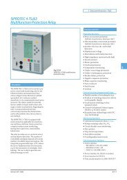
■ Design<br />
Operational display<br />
Hard disk access<br />
Fan/temperature status<br />
2 slots for 5.25" drives<br />
3.5" diskette<br />
drive<br />
AC power supply Interfaces for keyboard, Extension slots:<br />
mouse, 4 x USB 2.0,<br />
COM1, LPT1, VGA,<br />
Audio, Gigabit Ethernet<br />
2 x USB<br />
Power switch<br />
Optical drive<br />
4 x PCI, 2 x PCIe x1,<br />
1 x PCIe x16<br />
The <strong>SIMATIC</strong> <strong>PCS</strong> 7 Industrial Workstations of type Rack PC<br />
547B have a painted all-metal housing of 19" rack design which<br />
is particularly protected against dust by a filter and pressurized<br />
ventilation. This mechanically and electromechanically rugged<br />
housing has a service-friendly design. The <strong>SIMATIC</strong> <strong>PCS</strong> 7 Industrial<br />
Workstations of type Rack PC 547B can be positioned<br />
and installed horizontally or vertically. High-grade components<br />
with high MTBF values and monitoring functions for the inner<br />
housing temperature, fan and program execution permit reliable<br />
24-hour continuous operation at ambient temperatures between<br />
5 and 40 °C.<br />
The <strong>SIMATIC</strong> <strong>PCS</strong> 7 Industrial Workstations of type Rack PC<br />
547B have the following features:<br />
• Motherboard with future-oriented Intel architecture for modern<br />
Core 2 Duo processors, based on Intel 945G Express chipset<br />
• Powerful AGP graphics with Dynamic Video Memory, sound<br />
(Line In, Line Out, Mic.) and 10/100/1000 Mbit/s Ethernet RJ45<br />
port integrated onboard<br />
• PCI-Express technology (1 PCIe x16 and 2 PCIe x1 slots)<br />
• 6 slots for drives:<br />
- At the front: three 5.25" slots (1 occupied by DVD-ROM/<br />
DVD-RW) and<br />
- one 3.5" slot (occupied by diskette drive)<br />
- Inside: two 3.5" slots (occupied by 1 hard disk on the client,<br />
and 2 hard disks on the server and ES/OS single station)<br />
• Increased system availability through RAID 1 with 2 SATA<br />
hard disks and NCQ technology (Native Command Queuing)<br />
on the server and ES/OS single station<br />
• Second serial interface (for server) available (COM2)<br />
© <strong>Siemens</strong> AG 2007<br />
<strong>System</strong>-neutral components<br />
<strong>SIMATIC</strong> <strong>PCS</strong> 7 Industrial Workstation<br />
<strong>Siemens</strong> ST <strong>PCS</strong> 7 · November 2007<br />
Basic hardware<br />
• Total of 6 USB 2.0 interfaces (4 at rear, 2 at front)<br />
• High electromagnetic compatibility (CE-certified for industrial<br />
and office environments)<br />
• Dust protection by means of pressurized ventilation in conjunction<br />
with a front fan and a dust filter<br />
• PC front complies with IP30 degree of protection when the<br />
front door is closed<br />
• Front door can be locked to prevent unauthorized access to<br />
swap media, control elements and interfaces located at the<br />
front<br />
• Easy and fast installation and maintenance of PC components:<br />
access to the front drives through a hinged front door;<br />
only 3 screws to open the device<br />
• 3 LEDs on the front of the PC visualize the operating status:<br />
- Power (switched on)<br />
- HD (hard disk access)<br />
- Status (fan and temperature monitoring)<br />
• Suitable for easy mounting with telescopic rails<br />
• Easy to remove fixing bracket with handles<br />
• Card hold-down device to secure PC modules during transportation<br />
and to protect them from vibration and shock<br />
• Power supply unit with temperature-controlled fan<br />
• Power connector lock for the power supply cable<br />
• <strong>SIMATIC</strong> PC DiagMonitor diagnostics software for monitoring<br />
program execution (watchdog), temperature, fan speed, hard<br />
disk status and system failure (heartbeat); including operating<br />
hours counter<br />
• Can be integrated into the system diagnostics of the <strong>SIMATIC</strong><br />
<strong>PCS</strong> 7 asset management by means of <strong>SIMATIC</strong> PC DiagMonitor<br />
Restore DVD<br />
The operating system and <strong>SIMATIC</strong> <strong>PCS</strong> 7 software are preinstalled<br />
on the basic devices. Two restore DVDs are supplied for<br />
quickly restoring the delivered status if required.<br />
• Restore DVD 1 only contains the operating system with default<br />
settings for optimum <strong>PCS</strong> 7 operation<br />
• Restore DVD 2 contains a full installation (operating system<br />
plus ES/OS software including SQL server)<br />
2/11<br />
2
<strong>System</strong>-neutral components<br />
<strong>SIMATIC</strong> <strong>PCS</strong> 7 Industrial Workstation<br />
2 Basic hardware<br />
■ Technical specifications<br />
<strong>SIMATIC</strong> <strong>PCS</strong> 7 Industrial Workstation (single station/server/client)<br />
■ Technical specifications (cont.)<br />
Interchangeable drives<br />
Design and equipment features<br />
• Diskette drive 3.5" diskette drive 1.44 MB<br />
Design 19" rack, 4 HU, for horizontal and • DVD drive in ES/OS single station DVD writer (DVD±RW) 5.25" ATAPI<br />
Degree of protection to EN 60529<br />
Motherboard<br />
vertical installation, prepared for<br />
easy mounting with telescopic<br />
rails, 19" fixing bracket with handle,<br />
easy to remove<br />
IP30 with front door closed; IP20<br />
at rear<br />
FSC D2156-S21<br />
Read:<br />
• DVD-ROM: single layer 16x,<br />
dual layer 12x<br />
• DVD-R/+R: single layer 16x,<br />
dual layer 7x<br />
• DVD-RW/+RW 13x<br />
• CD-ROM/CD-R 48x, CD-RW 40x<br />
Chipset Intel 945G Express<br />
Write:<br />
CPU<br />
• DVD+R 18x, DVD+RW 8x,<br />
• <strong>Process</strong>or base<br />
• <strong>Process</strong>or / clock<br />
LGA 775<br />
Intel Core 2 Duo E6600 /<br />
2x2.4GHz<br />
DVD-R 18x, DVD-RW 6x<br />
• DVD+R9 (DL) 8x, DVD-R DL 8x<br />
• CD-R 48x, CD-RW 32x<br />
• Front Side Bus (FSB) 1066 MHz<br />
• DVD drive in server/client DVD-ROM 5.25" ATAPI<br />
• Second Level Cache<br />
Main memory (SDRAM)<br />
4 MB<br />
Read:<br />
• DVD-ROM: single layer 16x,<br />
dual layer 8x<br />
•Type Dual channel DDR2-667 SDRAM<br />
(PC2-5300)<br />
• DVD+R/RW, DVD-R/RW 8x,<br />
DVD-RAM 2x<br />
• Maximum configuration 4 memory bases in total<br />
(expandable to 4 GB)<br />
• CD-ROM, CD-R 32x,<br />
CD-RW 20x<br />
• Standard configuration Single station/server:<br />
2GB (2x1GB)<br />
Client: 1 GB (2 x 512 MB)<br />
Graphics card Intel GMA950 graphics controller<br />
(on board), 2D and 3D engine<br />
integrated in chipset, up to<br />
2048 x 1536 pixels with 75 Hz<br />
Motherboard slots 4 x PCI (max. 265 mm long)<br />
image refresh rate<br />
2 x PCIe x1<br />
1 x PCIe x16<br />
• Graphics memory Dynamic video memory technology<br />
(up to 224 MB)<br />
Slots for drives<br />
• Resolutions. frequencies, colors • Up to 800 x 600 at 120 Hz, 32 bit<br />
• On the front 1 x 3.5" (occupied by diskette<br />
colors<br />
• On the inside<br />
drive)<br />
3 x 5.25" (1 occupied by<br />
DVD-ROM/DVD±RW)<br />
2 x 3.5" for hard disk drives<br />
(2 occupied with server/single<br />
station; 1 occupied with client) Mouse<br />
• Up to 1280 x 1024 at 100 Hz,<br />
32 bit colors<br />
• Up to 2048 x 1536 at 75 Hz,<br />
16 bit colors<br />
Optical mouse<br />
RAID controller RAID controller Intel ICH7R with Interface modules / interfaces<br />
Intel Storage Manager software<br />
(onboard)<br />
• OS-LAN interface module 10/100/1000 Mbit/s Ethernet<br />
(RJ45) on board,<br />
Hard disks<br />
Broadcom BCM5751 controller<br />
• Storage volumes / features 250 GB / 3.5" SATA, 8 MB cache,<br />
7200 rpm, NCQ<br />
• Plant bus interface module (single<br />
station/server), alternatives<br />
• Single station/server SATA-RAID 1 (mirror) with 2 hard<br />
disks<br />
- RACK PC 547B BCE Ethernet network card RJ45 (PCI)<br />
10/100/1000 Mbit/s<br />
•Client 1 SATA hard disk<br />
- RACK PC 547B IE CP 1613 A2 communications<br />
processor<br />
•USB 6 x USB 2.0, 4 x at rear and 2 x at<br />
front, high current in each case<br />
•Serial Server: 1 x COM1 and 1 x COM2<br />
(each V.24), 9-contact Sub-D<br />
connector<br />
Single station/client: 1 x COM1<br />
(V.24), 9-contact Sub-D connector<br />
• Parallel 1 x LPT1 (25-pin, EPP and ECP)<br />
•Audio 1 x Line In; 1 x Micro In; 1 x Line<br />
Out (2 x 0.5 W/8 Ω); Realtek<br />
ALC262 Audio Codec<br />
•VGA 1 x Sub-D socket, 15-contact<br />
• Keyboard 1 x PS/2<br />
•Mouse 1 x PS/2<br />
2/12<br />
<strong>Siemens</strong> ST <strong>PCS</strong> 7 · November 2007<br />
© <strong>Siemens</strong> AG 2007
■ Technical specifications (cont.)<br />
Operating systems and diagnostics software<br />
ES/OS single station/client Microsoft Windows XP<br />
Professional MUI, 6 languages,<br />
selectable: German, English,<br />
French, Italian, Spanish, Chinese<br />
Server Microsoft Windows Server 2003<br />
(standard edition) MUI,<br />
6 languages, selectable:<br />
German, English, French, Italian,<br />
Spanish, Chinese<br />
<strong>System</strong>-tested <strong>SIMATIC</strong> industrial <strong>SIMATIC</strong> PC DiagMonitor<br />
software<br />
Monitoring/diagnostics functions<br />
Watchdog • Monitoring of program execution<br />
• Monitoring time adjustable in the<br />
software<br />
Temperature Violation of permissible operating<br />
temperature<br />
Fans Speed monitoring for:<br />
•Front fan<br />
• <strong>Process</strong>or fan<br />
• Power supply fan<br />
Displays Front LEDs<br />
• Power (device switched on)<br />
• HD (access to hard disk)<br />
• Status (fan/temperature<br />
monitoring)<br />
Safety<br />
Protection class Protection class I compliant with<br />
IEC 61140<br />
Safety directives EN 60950-1;<br />
UL60950;<br />
CSA C22.2 No. 60950-00<br />
Noise level<br />
Operation < 45 dB (A) to DIN 45635<br />
Electromagnetic compatibility (EMC)<br />
Emitted interference (AC) EN 55022 Class B; FCC Class A<br />
EN 61000-3-2 Class D,<br />
EN 61000-3-3<br />
Immunity to conducted interference ± 2 kV (to IEC 61000-4-4, burst)<br />
on the supply lines<br />
± 1 kV (to IEC 61000-4-5,<br />
symmetrical surge)<br />
± 2 kV (to IEC 61000-4-5,<br />
unsymmetrical surge)<br />
Immunity to interference on signal ± 2 kV (to IEC 61000-4-4, burst,<br />
lines<br />
length > 3 m)<br />
± 2 kV (to IEC 61000-4-5, symmetrical<br />
surge, length > 30 m)<br />
Immunity to static discharge ± 4 kV, contact discharge<br />
(to IEC 61000-4-2)<br />
± 8 kV, atmospheric discharge<br />
(to IEC 61000-4-2)<br />
Immunity to high-frequency 1 V/m, 2 to 2.7 GHz<br />
irradiation<br />
10 V/m, 80 MHz to 1 GHz and<br />
1.4 to 2 GHz, 80% AM<br />
(to IEC 61000-4-3)<br />
10 V, 10 kHz to 80 MHz<br />
(to IEC 61000-4-6)<br />
Magnetic field 100 A/m, 50 Hz/60 Hz<br />
(to IEC 61000-4-8)<br />
© <strong>Siemens</strong> AG 2007<br />
<strong>System</strong>-neutral components<br />
<strong>SIMATIC</strong> <strong>PCS</strong> 7 Industrial Workstation<br />
<strong>Siemens</strong> ST <strong>PCS</strong> 7 · November 2007<br />
Basic hardware<br />
■ Technical specifications (cont.)<br />
Climatic conditions<br />
Temperature Tested according to<br />
IEC 60068-2-2, IEC 60068-2-1,<br />
IEC 60068-2-14<br />
• Operation +5 ... +40 °C (no DVD writer<br />
operation),<br />
+5 ... +35 °C (without limitation)<br />
CPU up to 65 W power loss<br />
Gradient: max. 10 °C/h,<br />
no condensation<br />
• Storage/transport -20 ... +60 °C<br />
Gradient: max. 20 °C/h,<br />
no condensation<br />
Relative humidity Tested according to<br />
IEC 60068-2-78, IEC 60068-2-30<br />
• Operation 5 ... 80% at 25 °C<br />
(no condensation)<br />
Gradient: max. 10 °C/h,<br />
no condensation<br />
• Storage/transport 5 ... 95% at 25 °C<br />
(no condensation)<br />
Gradient: max. 20 °C/h,<br />
no condensation<br />
Mechanical environmental conditions<br />
Vibrations Tested according to<br />
IEC 60068-2-6, 10 cycles<br />
• Operation 20 ... 58 Hz, amplitude 0.015 mm;<br />
58 ... 200 Hz: 2 m/s²<br />
Note: No mechanical interferences<br />
are tolerable when writing<br />
with CD/DVD writers.<br />
• Storage/transport 5 ... 8.51 Hz, amplitude 3.5 mm;<br />
8.51 ... 500 Hz: 9.8 m/s²<br />
Shock Tested according to<br />
IEC 60068-2-27<br />
• Operation Half sine: 9.8 m/s², 20 ms,<br />
100 shocks per axis<br />
Note: No mechanical interferences<br />
are tolerable when writing<br />
with CD/DVD writers.<br />
• Storage/transport Half sine: 250 m/s², 6 ms,<br />
1000 shocks per axis<br />
Approvals<br />
CE living accommodation (emitted EN 61000-6-3:2001<br />
interference)<br />
CE industrial areas (noise immunity) EN 61000-6-2:2005<br />
cULus 60950-1<br />
2/13<br />
2
2<br />
<strong>System</strong>-neutral components<br />
<strong>SIMATIC</strong> <strong>PCS</strong> 7 Industrial Workstation<br />
Basic hardware<br />
■ Technical specifications (cont.)<br />
Power supply<br />
Nominal supply voltage 100 to 240 V AC, wide-range<br />
(90 to 264 V AC)<br />
Frequency 50 ... 60 Hz (minimum 47 to<br />
maximum 63 Hz, sinusoidal)<br />
Short-term voltage dip 16 ms at 0.85 of nominal supply<br />
voltage (max. 10 events per hour;<br />
recovery time min. 1 s)<br />
Power consumption (with 210 W 310 W (approx 68% efficiency)<br />
secondary)<br />
AC input current Continuous current up to 7 A (up<br />
to 30 A for 5 ms during startup)<br />
Max. current output •+3.3V: 24 A<br />
•+5V: 26 A<br />
(total power for +3.3 V and +5 V<br />
max. 190 W)<br />
• +12 V: 15 A<br />
• -12 V: 0.2 A<br />
•+5Vaux : 2 A<br />
Dimensions and weights<br />
Overall dimensions in mm<br />
433.5 x 176.5 x 445.5<br />
(W x H x D)<br />
Weight 16 ... 23 kg<br />
■ Selection and Ordering Data Order No.<br />
<strong>SIMATIC</strong> <strong>PCS</strong> 7 Industrial Workstation, single station version<br />
<strong>SIMATIC</strong> PC in 19" rack, without<br />
monitor, keyboard and printer;<br />
Core 2 Duo E6600 2.4 GHz processor,<br />
2 GB RAM (2 x 1 GB),<br />
sound, SATA-RAID 1 with 2 hard<br />
disks of 250 GB, graphics controller<br />
on board with dynamic<br />
video memory, DVD writer<br />
DVD±RW IDE, 3.5" diskette drive,<br />
optical mouse, Ethernet<br />
10/100/1000 Mbit/s (RJ45) on<br />
board for connection to OS-LAN;<br />
<strong>SIMATIC</strong> PC DiagMonitor diagnostics<br />
software and 2 restore<br />
DVDs;<br />
<strong>SIMATIC</strong> <strong>PCS</strong> 7 ES/OS software<br />
preinstalled<br />
Windows XP Professional MUI<br />
operating system<br />
(German, English, French, Italian,<br />
Spanish, Chinese)<br />
• <strong>SIMATIC</strong> <strong>PCS</strong> 7 ES/OS 547B<br />
BCE WXP<br />
Connection to plant bus with<br />
Ethernet network card RJ45<br />
(PCI) 10/100/1000 Mbit/s and<br />
Basic Communication Ethernet<br />
(BCE) for up to 8 automation<br />
systems (not fault-tolerant<br />
systems)<br />
6ES7 650-0NF07-0YX0 D)<br />
• <strong>SIMATIC</strong> <strong>PCS</strong> 7 ES/OS 547B<br />
IE WXP<br />
Connection to plant bus with<br />
CP 1613 A2 communications<br />
processor<br />
6ES7 650-0NF07-0YX1 D)<br />
2/14<br />
<strong>Siemens</strong> ST <strong>PCS</strong> 7 · November 2007<br />
© <strong>Siemens</strong> AG 2007<br />
■ Selection and Ordering Data Order No.<br />
<strong>SIMATIC</strong> <strong>PCS</strong> 7 Industrial Workstation, server version<br />
<strong>SIMATIC</strong> PC in 19" rack, without<br />
monitor, keyboard and printer;<br />
Core 2 Duo E6600 2.4 GHz processor,<br />
2 GB RAM (2 x 1 GB),<br />
sound, SATA-RAID 1 with 2 hard<br />
disks of 250 GB, graphics controller<br />
on board with dynamic<br />
video memory, DVD-ROM IDE,<br />
3.5" diskette drive, optical mouse,<br />
Ethernet 10/100/1000 Mbit/s<br />
(RJ45) on board for connection to<br />
OS-LAN;<br />
<strong>SIMATIC</strong> PC DiagMonitor diagnostics<br />
software and 2 restore<br />
DVDs;<br />
<strong>SIMATIC</strong> <strong>PCS</strong> 7 OS software for<br />
server preinstalled<br />
Windows Server 2003 MUI<br />
operating system<br />
(German, English, French, Italian,<br />
Spanish, Chinese)<br />
• <strong>SIMATIC</strong> <strong>PCS</strong> 7 OS Server 6ES7 650-0NH07-0YX0 D)<br />
547B BCE SRV03<br />
Connection to plant bus with<br />
Ethernet network card RJ45<br />
(PCI) 10/100/1000 Mbit/s and<br />
Basic Communication Ethernet<br />
(BCE) for up to 8 automation<br />
systems (not fault-tolerant<br />
systems)<br />
• <strong>SIMATIC</strong> <strong>PCS</strong> 7 OS Server 6ES7 650-0NH07-0YX1 D)<br />
547B IE SRV03<br />
Connection to plant bus with<br />
CP 1613 A2 communications<br />
processor<br />
<strong>SIMATIC</strong> <strong>PCS</strong> 7 Industrial Workstation, client version<br />
<strong>SIMATIC</strong> PC in 19" rack, without<br />
monitor, keyboard and printer;<br />
Core 2 Duo E6600 2.4 GHz processor,<br />
1 GB RAM (2 x 512 MB),<br />
SATA hard disk of 250 GB, graphics<br />
controller on board with<br />
dynamic video memory, DVD-<br />
ROM IDE, 3.5" diskette drive, optical<br />
mouse, Ethernet<br />
10/100/1000 Mbit/s (RJ45) on<br />
board for connection to OS-LAN;<br />
<strong>SIMATIC</strong> PC DiagMonitor diagnostics<br />
software and 2 restore<br />
DVDs;<br />
<strong>SIMATIC</strong> <strong>PCS</strong> 7 OS software for<br />
client preinstalled<br />
Windows XP Professional MUI<br />
operating system<br />
(German, English, French, Italian,<br />
Spanish, Chinese)<br />
• <strong>SIMATIC</strong> <strong>PCS</strong> 7 OS Client 547B<br />
WXP<br />
- without multi-VGA graphics 6ES7 650-0NG07-0YX0 D)<br />
card<br />
- with Multi-VGA graphics card 6ES7 650-0NG07-0YA0 D)<br />
"2 Screens"<br />
- with Multi-VGA graphics card 6ES7 650-0NG07-0YB0 D)<br />
"4 Screens"<br />
D) Subject to export regulations: AL: N, ECCN: 5D992B1
Additional and expansion components<br />
Memory modules for expanding<br />
the main memory<br />
• 512 MB memory expansion for<br />
<strong>SIMATIC</strong> Rack PC 547B<br />
(1 x 512 MB), DDR2-667<br />
SDRAM<br />
6ES7 648-2AF30-0HA0 B)<br />
• 1 GB memory expansion for<br />
<strong>SIMATIC</strong> Rack PC 547B<br />
(2 x 512 MB),<br />
DDR2-667 SDRAM,<br />
kit for dual-channel technology<br />
6ES7 648-2AF40-0HB0 B)<br />
• 2 GB memory expansion for<br />
<strong>SIMATIC</strong> Rack PC 547B<br />
(2 x 1 GB), DDR2-667 SDRAM,<br />
kit for dual-channel technology<br />
<strong>SIMATIC</strong> PC keyboard<br />
(USB connection)<br />
6ES7 648-2AF50-0HB0 B)<br />
• International key assignment<br />
Tower kit for <strong>SIMATIC</strong> <strong>PCS</strong> 7<br />
Industrial Workstations<br />
based on Rack PC 547B and<br />
IL 43<br />
6ES7 648-0CB00-0YA0<br />
• Tower kit for conversion of a<br />
Rack PC into an industrial<br />
Tower PC<br />
3-m power cable for Rack PC<br />
6ES7 648-1AA00-0XC0<br />
1)<br />
■ Selection and Ordering Data Order No.<br />
• For Great Britain 6ES7 900-0BA00-0XA0<br />
• For Switzerland 6ES7 900-0CA00-0XA0<br />
•For USA 6ES7 900-0DA00-0XA0<br />
•For Italy 6ES7 900-0EA00-0XA0<br />
•For China<br />
<strong>SIMATIC</strong> NET S7-REDCONNECT<br />
Upgrade<br />
For communication with faulttolerant<br />
AS systems, see page<br />
9/29<br />
6ES7 900-0FA00-0XA0<br />
B) Subject to export regulations: AL: N, ECCN: EAR99H<br />
1) The <strong>PCS</strong> 7 systems are delivered as standard with a "European power<br />
cable". The country-specific versions listed above are required for some<br />
countries.<br />
© <strong>Siemens</strong> AG 2007<br />
<strong>System</strong>-neutral components<br />
<strong>SIMATIC</strong> <strong>PCS</strong> 7 Industrial Workstation<br />
<strong>Siemens</strong> ST <strong>PCS</strong> 7 · November 2007<br />
Basic hardware<br />
■ Accessories<br />
Keyboards<br />
The <strong>SIMATIC</strong> <strong>PCS</strong> 7 Industrial Workstations are delivered without<br />
a keyboard. The <strong>SIMATIC</strong> PC keyboard with USB connection, for<br />
example, is suitable for process operation with <strong>SIMATIC</strong> <strong>PCS</strong> 7.<br />
The <strong>SIMATIC</strong> PC keyboard is a standard MF2 keyboard with<br />
105 keys, without additional special functions. It combines the<br />
convenience of an office keyboard with the EMC of an industrial<br />
device. Standards/approvals: UL 1950, CSA C22.2 No. 950,<br />
FCC Part 15, subpart B, class B, VDE-GS (EN 60950/ZHI/618),<br />
CE, C-TICK-Mark (Australia).<br />
Power supply cable for Rack PC<br />
The <strong>SIMATIC</strong> <strong>PCS</strong> 7 systems are delivered as standard with a<br />
"European power cable". This can be used in Germany, France,<br />
Spain, Netherlands, Belgium, Sweden, Austria and Finland.<br />
The country-specific versions listed in the Ordering data are required<br />
for other countries. The following picture shows the appearance<br />
of the power supply plugs:<br />
Country-specific power supply cables for Rack PC<br />
Tower Kit<br />
A Tower Kit for converting a <strong>SIMATIC</strong> <strong>PCS</strong> 7 Industrial Workstation<br />
of Rack PC design into an industrial Tower PC can be ordered<br />
as an option. The Tower Kit is suitable for <strong>SIMATIC</strong> <strong>PCS</strong> 7<br />
Industrial Workstations based on the Rack PC types 547B and<br />
IL 43.<br />
2/15<br />
2
<strong>System</strong>-neutral components<br />
<strong>SIMATIC</strong> <strong>PCS</strong> 7 Industrial Workstation<br />
2 Multi-VGA graphics cards<br />
■ Overview<br />
2/16<br />
<strong>Siemens</strong> ST <strong>PCS</strong> 7 · November 2007<br />
© <strong>Siemens</strong> AG 2007<br />
■ Technical specifications<br />
Multi-VGA graphics cards<br />
Memory 32 MB DDRAM per output<br />
• Graphics card "2 Screens" 2 x 32 MB<br />
• Graphics card "4 Screens" 4 x 32 MB<br />
Clock 360 MHz integrated RAMDAC<br />
Max. analog resolution per channel 2048 x 1536 at 24 bpp and 85 Hz<br />
Max. digital resolution per channel<br />
Electromagnetic compatibility<br />
(EMC)<br />
1280 x 1024<br />
• Emitted interference EN 55022 Class B<br />
• Noise immunity EN 50082<br />
Slot requirement 1 PCI slot<br />
■ Selection and Ordering Data Order No.<br />
Multi-VGA Graphics Card<br />
"2 Screens"<br />
for operating 2 process monitors<br />
on 1 station<br />
Type of delivery:<br />
Dual graphics card, driver CD,<br />
6ES7 652-0XX03-1XE0 B)<br />
The <strong>SIMATIC</strong> <strong>PCS</strong> 7 industrial workstations are supplied as standard<br />
with a graphics interface module for controlling one process<br />
monitor. The multi-VGA graphics cards "2 Screens" and<br />
"4 Screens" are available for multi-channel mode with 2 or up to<br />
4 process monitors.<br />
manual, 1 dual DVI cable for<br />
2 digital outputs, 2 adapters for<br />
VGA outputs<br />
Multi-VGA Graphics Card<br />
"4 Screens"<br />
for operating 4 process monitors<br />
6ES7 652-0XX03-1XE1 B)<br />
Using a multi-VGA graphics card, the visualization of a<br />
on 1 station<br />
project/subproject when engineering or a plant/unit in process Type of delivery:<br />
operation can be divided among up to 4 process monitors per<br />
operator station with application of different views. These<br />
project/plant sections can all be operated using just one keyboard<br />
and one mouse. Compared to single-channel mode, it is<br />
Quad graphics card, driver CD,<br />
manual, 2 dual DVI cables for<br />
4 digital outputs, 4 adapters for<br />
VGA outputs<br />
thus possible to enormously improve the efficiency, convenience<br />
and ergonomics of engineering and process control.<br />
B) Subject to export regulations: AL: N, ECCN: EAR99H
■ Overview<br />
Operating devices<br />
In addition to the mouse and <strong>SIMATIC</strong> PC keyboard described<br />
as operating devices in the Section "Basic hardware", you can<br />
find further devices such as fingerprint mouse, trackball or<br />
Ex-PC operator panel in the Catalog ST <strong>PCS</strong> 7.1 (Add-ons for<br />
the <strong>SIMATIC</strong> <strong>PCS</strong> 7 process control system).<br />
<strong>Process</strong> monitors<br />
© <strong>Siemens</strong> AG 2007<br />
<strong>System</strong>-neutral components<br />
<strong>SIMATIC</strong> <strong>PCS</strong> 7 Industrial Workstation<br />
Operator panels/monitors<br />
■ Technical specifications<br />
Monitor SCD 19101-D<br />
Screen 19" (48 cm) TFT color monitor,<br />
1280 x 1024 pixels,<br />
16 million colors<br />
Line frequency 50 ... 97 kHz<br />
Image refresh rate 30 ... 100 Hz<br />
Power supply 110/230 V AC<br />
Dimensions (WxHxD) in mm 465 x 444 x 91 (depth of<br />
stand 240)<br />
Degree of protection IP20<br />
Weight Approx. 10 kg<br />
Detailed technical data can be found in<br />
• Catalog ST PC "PC-based Automation" or<br />
• the Mall/CA 01 at "Automation systems - Monitors, printers and<br />
input devices for industry"<br />
■ Selection and Ordering Data Order No.<br />
SCD 19101-D industrial LCD<br />
monitor<br />
(same design as SCD 1898-I)<br />
Desktop unit, 230 V AC,<br />
48 cm (19") screen diagonal,<br />
horizontal frequency 50...97 kHz,<br />
6GF6 220-1DA01 B)<br />
We recommend the SCD 19101-D industrial monitor (LCD color IP20 degree of protection<br />
monitor) for the <strong>SIMATIC</strong> <strong>PCS</strong> 7 process control system.<br />
Additional and expansion components<br />
In addition, industrial LCD monitors with IP65 degree of protec- Connection cable<br />
tion (front) are available for installation in desks, control cabinets<br />
or 19" racks. These are available from:<br />
• the Catalog ST PC "PC-based Automation" or<br />
• Video + Touch, 1.8 m long<br />
• Video + Touch, 5 m long<br />
6AV8 107-0BA00-0AA0<br />
6AV8 107-0DA00-0AA0<br />
• the A&D Mall/CA 01 under "Automation <strong>System</strong>s – PC-based<br />
• Video + Touch, 10 m long 6AV8 107-0FA00-0AA0<br />
Automation - Expansion Components - Industrial LCD Moni- • Video, connecting cable 20 m 6AV8 107-0HB00-0AA0<br />
tors"<br />
long<br />
■ Benefits<br />
Outstanding characteristics of the SCD 19101-D LCD monitor<br />
include:<br />
7 Rugged, fail-safe and long-life industrial design:<br />
- High resistance to shock and vibration<br />
- Extremely high electromagnetic compatibility<br />
- Anti-glare and hardened mineral glass pane for high<br />
mechanical protection<br />
- IP20 degree of protection<br />
- Complies with CE standard "Industry"<br />
7 Modern design with exceptional ergonomics:<br />
- Sharp and high-contrast picture with uniform brightness<br />
- No flickering<br />
- Large reading angle up to 170° horizontal and vertical<br />
- Automatic picture adjustment (Auto Adjust)<br />
7 No X-rays<br />
7 Low energy consumption and heat development<br />
7 Small space requirement and low weight<br />
7 Configuration using on-screen display (OSD)<br />
7 Long service life<br />
B) Subject to export regulations: AL: N, ECCN: EAR99H<br />
<strong>Siemens</strong> ST <strong>PCS</strong> 7 · November 2007<br />
2/17<br />
2
<strong>System</strong>-neutral components<br />
<strong>SIMATIC</strong> <strong>PCS</strong> 7 Industrial Workstation<br />
2 Special configurations<br />
■ Overview<br />
The <strong>SIMATIC</strong> <strong>PCS</strong> 7 Industrial Workstations offered in the catalog<br />
section "Basic hardware" already cover the majority of applications.<br />
In the case of special system requirements, particularly<br />
if several supplementary/expansion components such as multi-<br />
VGA graphics card, signal module or memory expansion have<br />
to be integrated at the same time, we also offer the possibility for<br />
ordering completely assembled special configurations of these<br />
<strong>SIMATIC</strong> <strong>PCS</strong> 7 Industrial Workstations.<br />
A special <strong>SIMATIC</strong> <strong>PCS</strong> 7 Industrial Workstation can be compiled<br />
interactively on the Internet using a configurator, and its<br />
Order No. generated in the process. This can subsequently be<br />
transferred to the shopping cart for ordering.<br />
2/18<br />
<strong>Siemens</strong> ST <strong>PCS</strong> 7 · November 2007<br />
© <strong>Siemens</strong> AG 2007<br />
Configurator in the A&D Mall<br />
The configurator "Special <strong>SIMATIC</strong> <strong>PCS</strong> 7 Industrial Workstations"<br />
is integrated in the catalog & online ordering system "A&D<br />
Mall" (www.siemens.com/automation/mall). It can be accessed<br />
there in two manners:<br />
Selection using quick link "Configuration list"<br />
A selection window in which all available configurators are categorized<br />
according to technical criteria is opened when you click<br />
the quick link "Configuration list" on the right side of the A&D Mall<br />
(see figure). You can find the configurator "Special <strong>SIMATIC</strong><br />
<strong>PCS</strong> 7 Industrial Workstations" here in the category "<strong>Process</strong><br />
automation".<br />
Selection using the "<strong>Siemens</strong> A&D product tree"<br />
If you click the link "Products" at the second position in the horizontal<br />
primary navigation (see blue area at the top in the figure),<br />
the "<strong>Siemens</strong> A&D product tree" is displayed on the left. Navigate<br />
there from "<strong>Process</strong> automation" via "<strong>Process</strong> control systems",<br />
"<strong>SIMATIC</strong> <strong>PCS</strong> 7 V7.0" and "<strong>SIMATIC</strong> <strong>PCS</strong> 7 Industrial<br />
Workstations" on to "Special configurations". Select the<br />
"Configurators" tab here, and then the configurator "Special<br />
<strong>SIMATIC</strong> <strong>PCS</strong> 7 Industrial Workstations".
© <strong>Siemens</strong> AG 2007<br />
Starter systems<br />
3/2 <strong>SIMATIC</strong> <strong>PCS</strong> 7 BOX<br />
3/2 Introduction<br />
3/4 <strong>SIMATIC</strong> <strong>PCS</strong> 7 BOX RTX<br />
3/8 <strong>SIMATIC</strong> <strong>PCS</strong> 7 BOX 416<br />
3/13 Runtime Basic Packages<br />
<strong>Siemens</strong> ST <strong>PCS</strong> 7 · November 2007
3<br />
Starter systems<br />
<strong>SIMATIC</strong> <strong>PCS</strong> 7 BOX<br />
Introduction<br />
■ Overview<br />
<strong>SIMATIC</strong> <strong>PCS</strong> 7 AS RTX with<br />
WinAC RTX software controller<br />
Runtime system with<br />
AS functionality<br />
Scalable automation performance in the bottom performance range of<br />
<strong>SIMATIC</strong> <strong>PCS</strong> 7<br />
(for <strong>SIMATIC</strong> <strong>PCS</strong> 7 AS RTX, see page 10/4)<br />
<strong>SIMATIC</strong> <strong>PCS</strong> 7 BOX systems are compact and rugged industrial<br />
PCs as low-price starter solutions for process automation<br />
with <strong>SIMATIC</strong> <strong>PCS</strong> 7. They are available in two versions:<br />
• <strong>SIMATIC</strong> <strong>PCS</strong> 7 all-in-one system<br />
with functionality for automation (AS), HMI (OS) and engineering<br />
(ES)<br />
• <strong>SIMATIC</strong> <strong>PCS</strong> 7 Runtime system<br />
with AS and OS functionality<br />
Expanded by distributed process I/Os on the PROFIBUS, each<br />
version represents a complete process control system for small<br />
applications.<br />
■ Application<br />
The <strong>SIMATIC</strong> <strong>PCS</strong> 7 BOX starter systems can be used for various<br />
applications:<br />
• Small production applications<br />
• Enclosed subprocesses (package units)<br />
• Automation of a laboratory or test center<br />
As a fully adequate member of the <strong>SIMATIC</strong> <strong>PCS</strong> 7 range, they<br />
work with the <strong>PCS</strong> 7 standard system software, are scalable, and<br />
can be expanded without destroying the compatibility. However,<br />
the engineering and runtime licenses for AS and OS are limited<br />
to 2000 POs (process objects).<br />
Use as asset management station<br />
<strong>SIMATIC</strong> <strong>PCS</strong> 7 BOX can be incorporated into the PC diagnostics<br />
of the <strong>SIMATIC</strong> <strong>PCS</strong> 7 asset management using the <strong>SIMATIC</strong><br />
PC DiagMonitor software. Equipped as an all-in-one system with<br />
software licenses for <strong>SIMATIC</strong> PDM and <strong>SIMATIC</strong> <strong>PCS</strong> 7 asset<br />
management, they are additionally suitable for use as a maintenance<br />
station. For further information, see Chapter "Asset management".<br />
3/2<br />
<strong>SIMATIC</strong> <strong>PCS</strong> 7 BOX RTX with<br />
WinAC RTX software controller<br />
<strong>Siemens</strong> ST <strong>PCS</strong> 7 · November 2007<br />
<strong>SIMATIC</strong> <strong>PCS</strong> 7 BOX 416<br />
with WinAC Slot 416<br />
hardware controller<br />
Runtime systems with AS and<br />
OS functionality<br />
or all-in-one systems<br />
with AS, OS and ES functionality<br />
© <strong>Siemens</strong> AG 2007<br />
■ Design<br />
Two <strong>SIMATIC</strong> <strong>PCS</strong> 7 BOX systems with different performances<br />
are currently available:<br />
• <strong>SIMATIC</strong> <strong>PCS</strong> 7 BOX RTX with WinAC RTX software controller<br />
• <strong>SIMATIC</strong> <strong>PCS</strong> 7 BOX 416 with WinAC Slot 416 hardware controller<br />
Together with the compact <strong>SIMATIC</strong> <strong>PCS</strong> 7 AS RTX Microbox automation<br />
system (see page 10/4), these allow finer scaling of the<br />
automation performance in the bottom performance range of<br />
<strong>SIMATIC</strong> <strong>PCS</strong> 7. It is then possible to react more variably to individual<br />
customer requirements with small applications. With regard<br />
to the achievable quantity framework, the <strong>SIMATIC</strong> <strong>PCS</strong> 7<br />
BOX systems are approximately comparable with the following<br />
standard automation systems:<br />
• <strong>SIMATIC</strong> <strong>PCS</strong> 7 BOX 416 with an AS 416<br />
• <strong>SIMATIC</strong> <strong>PCS</strong> 7 BOX RTX with an AS 414<br />
In a direct comparison of the two systems, the <strong>SIMATIC</strong> <strong>PCS</strong> 7<br />
BOX RTX impresses primarily due to the following advantages:<br />
• Low price<br />
• Very fast program execution<br />
Particular advantages of the <strong>SIMATIC</strong> <strong>PCS</strong> 7 BOX 416 are:<br />
• High availability<br />
• Support of changes to the configuration during runtime (CiR)<br />
through the stand-alone WinAC Slot CPU<br />
ES<br />
PDM OS<br />
CP 5611<br />
onboard<br />
<strong>SIMATIC</strong> <strong>PCS</strong> 7 BOX<br />
CPU 416-2 24 V DC<br />
DP MPI/DP<br />
PROFIBUS DP PROFIBUS MPI/DP<br />
DP/PA<br />
link<br />
PROFIBUS PA<br />
Stand-alone operation using example of a <strong>SIMATIC</strong> <strong>PCS</strong> 7 BOX 416
ES<br />
Ethernet<br />
onboard<br />
Plant bus<br />
Ethernet<br />
onboard<br />
OS-LAN (Terminal bus)<br />
PDM OS<br />
CP 5611<br />
onboard<br />
PROFIBUS<br />
CPU 416-2 24 V DC<br />
DP MPI/DP<br />
DP/PA<br />
link<br />
OS<br />
server<br />
Automation<br />
systems<br />
<strong>SIMATIC</strong> <strong>PCS</strong> 7 BOX<br />
PROFIBUS MPI/DP<br />
PROFIBUS PA<br />
OS clients<br />
Engineering<br />
system<br />
Integration in the <strong>SIMATIC</strong> <strong>PCS</strong> 7 system network using example of the<br />
<strong>SIMATIC</strong> <strong>PCS</strong> 7 BOX 416<br />
<strong>SIMATIC</strong> <strong>PCS</strong> 7 BOX systems (<strong>SIMATIC</strong> <strong>PCS</strong> 7 BOX RTX as<br />
well as <strong>SIMATIC</strong> <strong>PCS</strong> 7 BOX 416) are based on the industrial<br />
<strong>SIMATIC</strong> Box PC 627B which permits combination of the frequently<br />
distributed <strong>PCS</strong> functionality for automation, HMI and<br />
engineering in one system. They use standard system software<br />
of <strong>SIMATIC</strong> <strong>PCS</strong> 7 V7.0, and are integrated in the <strong>SIMATIC</strong> <strong>PCS</strong> 7<br />
engineering and the <strong>PCS</strong> 7 project wizard. This guarantees full<br />
compatibility with <strong>SIMATIC</strong> <strong>PCS</strong> 7 V7.0.<br />
<strong>SIMATIC</strong> <strong>PCS</strong> 7 BOX can be configured either using the engineering<br />
software integrated in the system or a central engineering<br />
system. OS-specific changes in the configuration on the<br />
<strong>SIMATIC</strong> <strong>PCS</strong> 7 BOX or on the central engineering system can<br />
be downloaded online, i.e. without terminating OS process operation.<br />
<strong>SIMATIC</strong> <strong>PCS</strong> 7 BOX support ET 200M, ET 200ISP and ET 200S<br />
remote I/O stations connected over PROFIBUS DP by means of<br />
a comprehensive range of low-cost signal/function modules as<br />
well as intelligent field/process devices connected directly over<br />
PROFIBUS DP/PA.<br />
© <strong>Siemens</strong> AG 2007<br />
Starter systems<br />
<strong>SIMATIC</strong> <strong>PCS</strong> 7 BOX<br />
<strong>Siemens</strong> ST <strong>PCS</strong> 7 · November 2007<br />
Introduction<br />
<strong>SIMATIC</strong> <strong>PCS</strong> 7 BOX systems can be operated in stand-alone<br />
mode and also in the system network with other <strong>SIMATIC</strong> <strong>PCS</strong> 7<br />
system components. The two architectures are illustrated using<br />
examples of the <strong>SIMATIC</strong> <strong>PCS</strong> 7 BOX 416.<br />
A system produced with <strong>SIMATIC</strong> <strong>PCS</strong> 7 BOX can be expanded<br />
at any time by further <strong>SIMATIC</strong> <strong>PCS</strong> 7 hardware and software<br />
components. It is just as easy to integrate <strong>SIMATIC</strong> <strong>PCS</strong> 7 BOX<br />
into existing <strong>SIMATIC</strong> <strong>PCS</strong> 7 systems. The connections on the<br />
plant bus and OS-LAN (terminal bus) are made using the Ethernet<br />
interfaces integrated in the <strong>SIMATIC</strong> <strong>PCS</strong> 7 BOX.<br />
The engineering licenses as well as the runtime licenses for AS<br />
and OS are administered by the engineering software.<br />
With a <strong>SIMATIC</strong> <strong>PCS</strong> 7 BOX all-in-one system, the runtime licenses<br />
for AS and OS are components of the engineering software,<br />
and can be expanded by AS/OS Software Engineering<br />
PowerPacks to a maximum of 2000 POs.<br />
With a <strong>SIMATIC</strong> <strong>PCS</strong> 7 BOX runtime system, the OS Runtime licenses<br />
can be expanded by OS Software PowerPacks, the<br />
AS Runtime licenses by further AS Runtime licenses for 100 or<br />
1000 POs to a maximum of 2000 POs. The process objects of<br />
additional AS Runtime licenses are then added to process objects<br />
which already exist. The number and type (100 or 1000) of<br />
additional AS Runtime licenses are only limited by the expansion<br />
limit.<br />
3/3<br />
3
3<br />
Starter systems<br />
<strong>SIMATIC</strong> <strong>PCS</strong> 7 BOX<br />
<strong>SIMATIC</strong> <strong>PCS</strong> 7 BOX RTX<br />
■ Overview<br />
The <strong>SIMATIC</strong> <strong>PCS</strong> 7 BOX RTX equipped with a WinAC RTX software<br />
controller features an exceptional price/performance ratio.<br />
With regard to the automation performance, it is positioned<br />
slightly below the <strong>SIMATIC</strong> <strong>PCS</strong> 7 BOX 416, but is primarily characterized<br />
by its very fast program execution.<br />
The WinAC RTX software controller working on the <strong>SIMATIC</strong><br />
Box PC 627B basic hardware only generates a low basic load,<br />
and particularly exhibits its strengths in applications characterized<br />
by real-time demands and a deterministic response.<br />
3/4<br />
<strong>Siemens</strong> ST <strong>PCS</strong> 7 · November 2007<br />
© <strong>Siemens</strong> AG 2007<br />
■ Design<br />
All-metal enclosure,<br />
rack-mountable, also suitable<br />
for portrait assembly<br />
1 vacant PCI expansion slot,<br />
e.g. for multi-VGA<br />
graphics card<br />
DP interface (CP 5613)<br />
Power supply<br />
24 V DC<br />
On/off button<br />
Optical drive<br />
DVD +/- R/RW<br />
1 x DVI-I (VGA via<br />
supplied adapter)<br />
Slot for CompactFlash<br />
card (accessible from<br />
outside)<br />
COM1: Serial<br />
interface 1<br />
4 x USB 2.0 interfaces<br />
2 x Gigabit Ethernet<br />
connection for<br />
10/100/1000 Mbit/s<br />
DP interface<br />
Power supply fan<br />
<strong>SIMATIC</strong> <strong>PCS</strong> 7 BOX RTX design<br />
<strong>SIMATIC</strong> <strong>PCS</strong> 7 BOX RTX systems are offered in the form of<br />
two product bundles:<br />
• Preinstalled <strong>SIMATIC</strong> <strong>PCS</strong> 7 all-in-one system with AS, ES<br />
and OS functionality,<br />
including AS/OS Engineering and Runtime licenses for<br />
250 POs<br />
• Preinstalled <strong>SIMATIC</strong> <strong>PCS</strong> 7 runtime system with AS and OS<br />
functionality,<br />
including AS/OS Runtime license for 250 POs<br />
These bundles can be extended by the following expansion<br />
components (see also page 2/15 and catalog on PC-based<br />
Automation):<br />
• <strong>SIMATIC</strong> <strong>PCS</strong> 7 PowerPacks/Runtime licenses for up to<br />
2000 POs<br />
• AS/OS Software Engineering PowerPack for all-in-one system<br />
• OS Software Single Station PowerPack and AS Runtime license<br />
for runtime system<br />
• <strong>SIMATIC</strong> PDM package for <strong>PCS</strong> 7<br />
• <strong>SIMATIC</strong> PC keyboard<br />
• LC and CRT displays for office and industrial environments
© <strong>Siemens</strong> AG 2007<br />
Starter systems<br />
<strong>SIMATIC</strong> <strong>PCS</strong> 7 BOX<br />
<strong>SIMATIC</strong> <strong>PCS</strong> 7 BOX RTX<br />
■ Technical specifications<br />
■ Technical specifications (cont.)<br />
Basic hardware: <strong>SIMATIC</strong> Box PC 627B<br />
Monitoring/diagnostics functions<br />
Design and equipment features<br />
Watchdog • Monitoring of program execu-<br />
Design Rack-mountable device with rugged<br />
metal enclosure, suitable for<br />
wall and portrait mounting<br />
tion<br />
• Can be parameterized for fault<br />
scenario or restart<br />
Degree of protection to EN 60529 IP20<br />
• Monitoring time adjustable in<br />
the software<br />
CPU<br />
Temperature • <strong>Process</strong>or temperature<br />
• <strong>Process</strong>or Intel Core 2 Duo T7400 2.16 GHz<br />
• Air inlet temperature<br />
• Front Side Bus 667 MHz<br />
• Temperature in vicinity of power<br />
• Second Level Cache 4 MB<br />
supply<br />
Chipset Intel 945 GM<br />
(via <strong>SIMATIC</strong> PC DiagMonitor<br />
and <strong>SIMATIC</strong> <strong>PCS</strong> 7 Asset Man-<br />
Main memory 2 GB DDR2-667 SDRAM<br />
agement)<br />
(2 x 1 GB)<br />
Fans • Failure of device fan and power<br />
Graphics<br />
supply fan<br />
• Graphics controller Intel 2D/3D GMA950, integrated<br />
in chipset<br />
(via <strong>SIMATIC</strong> PC DiagMonitor<br />
and <strong>SIMATIC</strong> <strong>PCS</strong> 7 Asset Management)<br />
•Graphics memory Dynamic video memory 8 to<br />
128 MB<br />
Operating hours counter (via <strong>SIMATIC</strong> PC DiagMonitor<br />
and <strong>SIMATIC</strong> <strong>PCS</strong> 7 Asset Man-<br />
• Resolutions/colors/frequencies • VGA: Max. 1600 x 1200 /<br />
agement)<br />
32 bit colors / 85 Hz<br />
• DVI: Max. 1600 x 1200 /<br />
32 bit colors / 60 Hz<br />
Displays • Two-digit 7-segment display for<br />
visualization of POST codes<br />
during BIOS booting<br />
Drives<br />
• Two programmable status<br />
•Flash drive For CompactFlash card<br />
LEDs<br />
• Hard disk 3.5" SATA, 160 GB<br />
Safety<br />
• Optical drive DVD ± R/RW<br />
Protection class Protection class I compliant with<br />
IEC 61140<br />
• Diskette drive Connectable via USB (not<br />
included in scope of delivery)<br />
Safety directives EN 61131-2; UL508; CSA C22.2<br />
No 142<br />
Interfaces<br />
Noise level<br />
• PROFIBUS (12 Mbit/s) 1 x 9-contact Sub-D socket,<br />
CP 5611-compatible,<br />
Operation < 55 dB (A) to DIN 45635-1<br />
1 x 9-contact Sub-D socket, Electromagnetic compatibility<br />
CP 5613<br />
(EMC)<br />
• Ethernet 2 x 10/100/1000 Mbit/s (RJ 45) Emitted interference EN 55022 Class B; EN 61000-3-2<br />
•USB 4 x USB 2.0/high-speed<br />
(2 x high-current)<br />
Class D<br />
EN 61000-3-3; FCC Class A<br />
•Serial 1 x COM1 (V.24), 9-contact Sub-<br />
D connector<br />
Immunity to conducted interference<br />
on the supply lines<br />
± 2 kV (to IEC 61000-4-4; burst)<br />
± 1 kV (to IEC 61000-4-5;<br />
• Parallel -<br />
symmetrical surge)<br />
• Graphics connection 1 x DVI-I (DVI/VGA combined):<br />
± 2 kV (to IEC 61000-4-5;<br />
asymmetrical surge)<br />
• DVI: digital<br />
• VGA analog<br />
Immunity to interference on signal<br />
lines<br />
± 1 kV (to IEC 61000-4-4; burst;<br />
length < 3 m)<br />
• Keyboard/mouse Connectable via USB (keyboard<br />
± 2 kV (to IEC 61000-4-4; burst;<br />
not included in scope of deliv-<br />
length > 3 m)<br />
ery)<br />
± 2 kV (to IEC 61000-4-5; surge;<br />
Operating system and diagnos-<br />
length > 30 m)<br />
tics software<br />
Immunity to static discharge ± 6 kV contact discharge<br />
Operating system Windows XP Professional MUI<br />
(to IEC 61000-4-2)<br />
<strong>System</strong>-tested <strong>SIMATIC</strong> industrial<br />
software<br />
preinstalled on hard disk and<br />
enclosed on restore DVD, no<br />
activation necessary<br />
<strong>SIMATIC</strong> PC DiagMonitor<br />
Immunity to high-frequency irradiation<br />
± 8 kV air discharge (to<br />
IEC 61000-4-2)<br />
10 V/m, 80 to 1000 MHz and<br />
1.4 to 2 GHz, 80% AM<br />
(to IEC 61000-4-3)<br />
1 V/m, 2 to 2.7 GHz, 80% AM<br />
(to IEC 61000-4-3)<br />
10 V, 9 kHz to 80 MHz, 80% AM<br />
(to IEC 61000-4-6)<br />
Immunity to magnetic fields 100 A/m, 50/60 Hz<br />
(to IEC 61000-4-8)<br />
<strong>Siemens</strong> ST <strong>PCS</strong> 7 · November 2007<br />
3/5<br />
3
3<br />
Starter systems<br />
<strong>SIMATIC</strong> <strong>PCS</strong> 7 BOX<br />
<strong>SIMATIC</strong> <strong>PCS</strong> 7 BOX RTX<br />
■ Technical specifications (cont.)<br />
■ Technical specifications (cont.)<br />
Climatic conditions<br />
Automation: WinAC software PLC<br />
Temperature Tested according to<br />
CPU WinAC RTX software controller<br />
IEC 60068-2-1, IEC 60068-2-2,<br />
for <strong>SIMATIC</strong> Box PC 627B with<br />
IEC 60068-2-14<br />
Windows XP Professional operat-<br />
• Operation • +5 to +45 °C (with DVD writer,<br />
only up to +40 °C)<br />
ing system, preconfigured for<br />
<strong>SIMATIC</strong> <strong>PCS</strong> 7<br />
• +5 to +50 °C (power of all slots<br />
All-in-one system<br />
max. 20 W)<br />
Preinstalled software/license <strong>PCS</strong> 7 Engineering Software<br />
• +5 to +55 °C (power of all slots<br />
V7.0 for AS/OS<br />
max. 10 W)<br />
Number of process objects 250 POs (expandable per<br />
• Storage/transport -20 to +60 °C<br />
(AS/OS engineering and runtime) PowerPack to 2000 POs)<br />
• Gradient Operation: max. 10 °C/h; stor- Runtime system<br />
age: 20 °C/h, no condensation<br />
Preinstalled software/license <strong>PCS</strong> 7 OS Software Single<br />
Relative humidity<br />
• Operation<br />
• Storage/transport<br />
Mechanical environmental conditions<br />
Tested according to<br />
IEC 60068-2-78, IEC 60068-2-30<br />
5 to 80% at 25 °C<br />
(no condensation)<br />
5 to 95% at 25 °C<br />
(no condensation)<br />
Number of process objects<br />
(runtime)<br />
Station V7.0 and<br />
<strong>SIMATIC</strong> <strong>PCS</strong> 7 AS Runtime<br />
license<br />
• 250 POs for OS (expandable<br />
per PowerPack to 2000 POs)<br />
• 250 POs for AS (expandable<br />
per AS Runtime license)<br />
Vibrations Tested according to<br />
IEC 60068-2-6<br />
• Operation 10 to 58 Hz: 0.075 mm, 58 to<br />
500 Hz: 9.8 m/s²<br />
Limitation with DVD writer:<br />
10 to 58 Hz: 0.019 mm /<br />
58 to 500 Hz: 2.5 m/s²<br />
Limitation with portrait assembly:<br />
10 to 58 Hz: 0.0375 mm / 58 to<br />
500 Hz: 4.9 m/s²<br />
• Storage/transport 5 to 9 Hz: 3.5 mm, 9 to 500 Hz:<br />
9.8 m/s²<br />
Shock Tested according to<br />
IEC 60068-2-27, IEC 60068-2-29<br />
• Operation 50 m/s², 30 ms<br />
Limitation with portrait assembly:<br />
25 m/s², 30 ms<br />
• Storage/transport<br />
Approvals<br />
CE living accommodation<br />
250 m/s², 6 ms<br />
• Emitted interference EN 61000-6-3: 2001<br />
• Noise immunity<br />
CE industrial environment<br />
EN 61000-6-1: 2001<br />
• Emitted interference EN 61000-6-4: 2001<br />
• Noise immunity EN 61000-6-2: 2005<br />
cULus<br />
Power supply (electrically<br />
isolated)<br />
UL 60950-1, Report E11 5352<br />
and CAN/CSA-C22.2 No. 60950-<br />
1; UL508 and CAN/CSA-C22.2<br />
No. 142;<br />
Power supply 24 V DC (-15% / +20%), SELV<br />
DC input current Continuous current up to 8 A (up<br />
to 14 A for 30 s during startup)<br />
Max. power consumption<br />
(at 24 V DC)<br />
Dimensions and weights<br />
210 W<br />
Dimensions including DVD writer<br />
(W x H x D) in mm<br />
297 x 267 x 100<br />
Weight Approx. 7 kg<br />
3/6<br />
<strong>Siemens</strong> ST <strong>PCS</strong> 7 · November 2007<br />
© <strong>Siemens</strong> AG 2007
■ Selection and Ordering Data Order No.<br />
<strong>SIMATIC</strong> <strong>PCS</strong> 7 BOX RTX all-inone<br />
system (ES, OS and AS)<br />
assembled and preinstalled,<br />
comprising:<br />
• <strong>SIMATIC</strong> Box PC 627B, 24 V<br />
DC, with Windows XP Professional<br />
MUI operating system<br />
(German, English, French, Italian,<br />
Spanish), WinAC RTX software<br />
controller and <strong>SIMATIC</strong><br />
PC DiagMonitor diagnostics<br />
software<br />
• Mouse<br />
• <strong>SIMATIC</strong> <strong>PCS</strong> 7 Engineering<br />
Software V7.0 for AS/OS including<br />
AS/OS Runtime license for<br />
productive operation, 250 POs,<br />
5 languages (German, English,<br />
French, Italian, Spanish), floating<br />
license for 1 user<br />
6ES7 650-2QA07-0YX0 D)<br />
<strong>SIMATIC</strong> <strong>PCS</strong> 7 BOX RTX<br />
runtime system (OS and AS)<br />
assembled and preinstalled,<br />
comprising:<br />
• <strong>SIMATIC</strong> Box PC 627B, 24 V<br />
DC, with Windows XP Professional<br />
MUI operating system<br />
(German, English, French, Italian,<br />
Spanish), WinAC RTX software<br />
controller and <strong>SIMATIC</strong><br />
PC DiagMonitor diagnostics<br />
software<br />
• Mouse<br />
• <strong>SIMATIC</strong> <strong>PCS</strong> 7 OS Software<br />
Single Station V7.0, 250 POs,<br />
5 languages (German, English,<br />
French, Italian, Spanish), single<br />
license for 1 installation<br />
• <strong>SIMATIC</strong> <strong>PCS</strong> 7 AS Runtime<br />
license, 250 POs<br />
5 languages (German, English,<br />
French, Italian, Spanish), single<br />
license for 1 installation<br />
6ES7 650-2QB07-0YX0 D)<br />
Additional and expansion components<br />
<strong>SIMATIC</strong> <strong>PCS</strong> 7 PowerPacks for all-in-one system<br />
<strong>SIMATIC</strong> <strong>PCS</strong> 7 PowerPack<br />
Engineering Software AS/OS<br />
V7.0<br />
for extending the engineering<br />
software for AS/OS<br />
5 languages (German, English,<br />
French, Italian, Spanish), executes<br />
with Windows<br />
XP Professional, floating license<br />
for 1 user<br />
Type of delivery: License key<br />
disk, emergency key disk, certificate<br />
of license, terms and conditions<br />
• From 250 to 1000 POs, including<br />
AS/OS Runtime license<br />
6ES7 658-5AB07-0YD5<br />
• From 1000 to 2000 POs, including<br />
AS/OS Runtime license<br />
6ES7 658-5AC07-0YD5<br />
D) Subject to export regulations: AL: N, ECCN: 5D992B1<br />
© <strong>Siemens</strong> AG 2007<br />
Starter systems<br />
<strong>SIMATIC</strong> <strong>PCS</strong> 7 BOX<br />
<strong>SIMATIC</strong> <strong>PCS</strong> 7 BOX RTX<br />
■ Selection and Ordering Data Order No.<br />
<strong>SIMATIC</strong> <strong>PCS</strong> 7 PowerPacks/licenses for runtime system<br />
<strong>SIMATIC</strong> <strong>PCS</strong> 7 PowerPack<br />
OS Software Single Station<br />
V7.0<br />
for extending the OS Software<br />
Single Station<br />
5 languages (German, English,<br />
French, Italian, Spanish), executes<br />
with Windows<br />
XP Professional, single license<br />
for 1 installation<br />
Type of delivery: License key<br />
disk, emergency key disk, certificate<br />
of license, terms and conditions<br />
• From 250 POs to 1000 POs 6ES7 658-2AB07-0YD0<br />
• From 1000 POs to 2000 POs 6ES7 658-2AC07-0YD0<br />
<strong>SIMATIC</strong> <strong>PCS</strong> 7 AS Runtime<br />
license (can be added to existing<br />
licenses)<br />
5 languages (German, English,<br />
French, Italian, Spanish), executes<br />
with Windows<br />
XP Professional, single license for<br />
1 installation<br />
Type of delivery:<br />
License key disk, certificate of<br />
license, terms and conditions<br />
• 100 POs 6ES7 653-2BA00-0XB5<br />
• 1000 POs 6ES7 653-2BB00-0XB5<br />
<strong>SIMATIC</strong> PDM<br />
<strong>SIMATIC</strong> PDM <strong>PCS</strong> 7 V6.0 6ES7 658-3LX06-0YA5<br />
Complete package for integration<br />
into the engineering toolset<br />
of the <strong>SIMATIC</strong> <strong>PCS</strong> 7 engineering<br />
system<br />
5 languages (German, English,<br />
French, Italian, Spanish), executes<br />
with Windows 2000 Professional<br />
or Windows<br />
XP Professional, floating license<br />
for 1 user, with:<br />
• <strong>SIMATIC</strong> PDM Basic<br />
• Option "Integration in<br />
STEP 7/<strong>PCS</strong> 7"<br />
• Option "Routing through S7-<br />
400"<br />
• Option "128 TAGs"<br />
Software and electronic documentation<br />
on toolset DVD<br />
Type of delivery:<br />
• License key disk, emergency<br />
key disk, certificate of license,<br />
terms and conditions<br />
• 2 CDs with <strong>SIMATIC</strong> PDM V6.0<br />
and device library<br />
Note:<br />
TAG options and PowerPacks:<br />
see page 4/14<br />
Further <strong>SIMATIC</strong> <strong>PCS</strong> 7 system<br />
software<br />
• <strong>SIMATIC</strong> BATCH: see Section<br />
"Batch automation"<br />
• <strong>SIMATIC</strong> <strong>PCS</strong> 7 asset-management:<br />
see Section "Asset<br />
management"<br />
<strong>SIMATIC</strong> PC keyboard<br />
(USB connection)<br />
• International key assignment 6ES7 648-0CB00-0YA0<br />
<strong>Siemens</strong> ST <strong>PCS</strong> 7 · November 2007<br />
3/7<br />
3
3<br />
Starter systems<br />
<strong>SIMATIC</strong> <strong>PCS</strong> 7 BOX<br />
<strong>SIMATIC</strong> <strong>PCS</strong> 7 BOX 416<br />
■ Overview<br />
The <strong>SIMATIC</strong> <strong>PCS</strong> 7 BOX 416 equipped with a WinAC Slot 416<br />
V4.0 hardware controller is based like the <strong>SIMATIC</strong> <strong>PCS</strong> 7 BOX<br />
RTX on the industrial PC <strong>SIMATIC</strong> Box PC 627B. With regards to<br />
the automation performance, it is positioned slightly above the<br />
<strong>SIMATIC</strong> <strong>PCS</strong> 7 BOX RTX, and is particularly recommendable if<br />
high availability or changes to the configuration during operation<br />
(CiR) are relevant factors for the selection.<br />
3/8<br />
<strong>Siemens</strong> ST <strong>PCS</strong> 7 · November 2007<br />
© <strong>Siemens</strong> AG 2007<br />
■ Design<br />
RUN/STOP LEDs<br />
RUN mode switch<br />
Backup battery connection<br />
MPI/DP interface<br />
External connection<br />
24 V DC supply<br />
DP interface<br />
Power supply<br />
24 V DC<br />
On/off button<br />
Optical drive<br />
DVD +/- R/RW<br />
All-metal enclosure,<br />
rack-mountable, also<br />
suitable for portrait<br />
assembly<br />
1 x DVI-I (VGA via<br />
supplied adapter)<br />
1 vacant PCI expansion<br />
slot, e.g. for multi-VGA<br />
graphics card<br />
Slot for CompactFlash<br />
card (accessible from<br />
outside)<br />
COM1: Serial interface 1<br />
4 x USB 2.0 interfaces<br />
2 x Gigabit Ethernet<br />
connection for<br />
10/100/1000 Mbit/s<br />
DP interface<br />
Power supply fan<br />
Design of <strong>SIMATIC</strong> <strong>PCS</strong> 7 BOX 416<br />
<strong>SIMATIC</strong> <strong>PCS</strong> 7 BOX 416 systems are offered in the form of<br />
two product bundles:<br />
• Preinstalled <strong>SIMATIC</strong> <strong>PCS</strong> 7 all-in-one system with AS, ES<br />
and OS functionality,<br />
including AS/OS Engineering and Runtime licenses for<br />
250 POs<br />
• Preinstalled <strong>SIMATIC</strong> <strong>PCS</strong> 7 runtime system with AS and OS<br />
functionality,<br />
including AS/OS Runtime license for 250 POs<br />
These bundles can be extended by the following expansion<br />
components (see also page 2/15 and catalog on PC-based<br />
Automation):<br />
• <strong>SIMATIC</strong> <strong>PCS</strong> 7 PowerPacks/Runtime licenses for up to<br />
2000 POs<br />
- AS/OS Software Engineering PowerPack for all-in-one system<br />
- OS Software Single Station PowerPack and AS Runtime<br />
license for runtime system<br />
• <strong>SIMATIC</strong> PDM package for <strong>PCS</strong> 7<br />
• <strong>SIMATIC</strong> PC keyboard<br />
• LC and CRT displays for office and industrial environments<br />
• SITOP smart power supply 230 AC/24 V DC, 240 W<br />
• SITOP DC UPS module 15 A with RS 232 interface<br />
• DC UPS software for further processing of the signals sent by<br />
the DC UPS module with RS 232 interface on the PC (status<br />
visualization as well as definition of response to various operating<br />
states of the DC UPS module), executes with Windows<br />
NT, 2000 and XP; freeware for downloading at www.siemens.com/sitop<br />
• SITOP battery module 24 V DC/20 A/7 Ah for DC UPS module<br />
15 A
© <strong>Siemens</strong> AG 2007<br />
Starter systems<br />
<strong>SIMATIC</strong> <strong>PCS</strong> 7 BOX<br />
<strong>SIMATIC</strong> <strong>PCS</strong> 7 BOX 416<br />
■ Function<br />
■ Technical specifications<br />
WinAC Slot 416 V4.0<br />
Basic hardware: <strong>SIMATIC</strong> Box PC 627B<br />
Through use of the WinAC Slot 416 V4.0, it is possible for the au-<br />
Design and equipment features<br />
tomation program in the Slot CPU to execute completely auton- Design Rack-mountable device with rugomously<br />
from the <strong>SIMATIC</strong> Box PC and its Windows operating<br />
system. Therefore the system can be restarted even if the<br />
ged metal enclosure, suitable for<br />
wall and portrait mounting<br />
<strong>SIMATIC</strong> Box PC is switched off or faulty. 24 V DC from a separate<br />
source is connected to the Slot CPU to provide a power supply<br />
independent of the PC. Neither software faults on the PC<br />
Degree of protection to EN 60529<br />
CPU<br />
IP20<br />
side, nor a power loss, nor rebooting of the PC have an effect on • <strong>Process</strong>or Intel Core 2 Duo T7400 2.16 GHz<br />
execution of the automation program in the Slot CPU.<br />
• Front Side Bus 667 MHz<br />
If one of the following events occurs, the automation program is<br />
immediately informed and can thus react accordingly, e.g. by intermediate<br />
storage of production data and transfer of the system<br />
• Second Level Cache<br />
Chipset<br />
4 MB<br />
Intel 945 GM<br />
to a defined status:<br />
Main memory 2 GB DDR2-667 SDRAM<br />
• Shutting-down of the Windows operating system<br />
(2 x 1 GB)<br />
• Fault in the Windows operating system ("blue screen")<br />
Graphics<br />
• Failure of PC-internal communication<br />
• Switching-off of the PC (Separate 24 V DC supply required)<br />
With the <strong>SIMATIC</strong> <strong>PCS</strong> 7 BOX 416, the process I/O is connected<br />
• Graphics controller<br />
• Graphics memory<br />
Intel 2D/3D GMA950, integrated<br />
in chipset<br />
Dynamic video memory 8 to<br />
128 MB<br />
via the two PROFIBUS DP ports of the WinAC Slot 416 V4.0. In<br />
conjunction with <strong>SIMATIC</strong> <strong>PCS</strong> 7 V7.0, the WinAC Slot 416 V4.0<br />
also permits changes to the configuration during operation<br />
(CiR). The type and scope of online modifications depend on the<br />
process I/O used.<br />
Since <strong>SIMATIC</strong> PDM can only access field devices on the<br />
PROFIBUS DP via the onboard CP 5611 communications pro-<br />
• Resolutions/colors/frequencies<br />
Drives<br />
• Flash drive<br />
• VGA: Max. 1600 x 1200 /<br />
32 bit colors / 85 Hz<br />
• DVI: Max. 1600 x 1200 /<br />
32 bit colors / 60 Hz<br />
For CompactFlash card<br />
cessor, an additional link is required between the DP port and • Hard disk 3.5" SATA, 160 GB<br />
the CP 5611. The plug required belongs to the scope of delivery<br />
of the <strong>SIMATIC</strong> <strong>PCS</strong> 7 BOX 416.<br />
• Optical drive DVD ± R/RW<br />
Use with <strong>SIMATIC</strong> BATCH<br />
• Diskette drive Connectable via USB (not<br />
included in scope of delivery)<br />
<strong>SIMATIC</strong> <strong>PCS</strong> 7 BOX 416 systems can also be used for automa- Interfaces<br />
tion of batch processes with <strong>SIMATIC</strong> BATCH. The capacity of<br />
<strong>SIMATIC</strong> BATCH is limited to 10 UNITs (instances of plant units)<br />
in this case. The following <strong>SIMATIC</strong> BATCH option packages can<br />
be executed on the <strong>SIMATIC</strong> <strong>PCS</strong> 7 BOX in addition to the SI-<br />
MATIC BATCH Server Basic Package for up to 10 UNITs:<br />
• PROFIBUS/MPI<br />
• Ethernet<br />
1 x 9-contact Sub-D socket,<br />
12 Mbit/s (electrically isolated,<br />
CP 5611-compatible)<br />
2 x 10/100/1000 Mbit/s (RJ 45)<br />
• Batch <strong>Control</strong> Center<br />
• Recipe <strong>System</strong><br />
• Batch Planning<br />
•USB<br />
•Serial<br />
4 x USB 2.0/high-speed<br />
(2 x high-current)<br />
1 x COM1 (V.24), 9-contact<br />
Sub-D connector<br />
• Hierarchical Recipe<br />
• Parallel -<br />
• ROP Library<br />
• Graphics connection 1 x DVI-I (DVI/VGA combined):<br />
• Separation Procedures/Formulas<br />
• DVI: digital<br />
Use with <strong>SIMATIC</strong> Route <strong>Control</strong><br />
• VGA analog<br />
<strong>SIMATIC</strong> <strong>PCS</strong> 7 BOX 416 systems are not only suitable for automation<br />
of batch processes with <strong>SIMATIC</strong> BATCH, but also for<br />
control of material transports with <strong>SIMATIC</strong> Route <strong>Control</strong>. The<br />
capacity of <strong>SIMATIC</strong> Route <strong>Control</strong> is limited to 30 simultaneous<br />
material transports in this case. The <strong>SIMATIC</strong> Route <strong>Control</strong><br />
• Keyboard/mouse<br />
Operating system and<br />
diagnostics software<br />
Connectable via USB (keyboard<br />
not included in scope of delivery)<br />
Server and <strong>SIMATIC</strong> Route <strong>Control</strong> Center runtime software is Operating system Windows XP Professional MUI<br />
then executed on the <strong>SIMATIC</strong> <strong>PCS</strong> 7 BOX 416. The Route Con-<br />
preinstalled on hard disk and<br />
trol Engineering is also possible on a <strong>SIMATIC</strong> <strong>PCS</strong> 7 BOX 416<br />
all-in-one system.<br />
enclosed on restore DVD, no<br />
activation necessary<br />
<strong>System</strong>-tested <strong>SIMATIC</strong> industrial<br />
software<br />
<strong>SIMATIC</strong> PC DiagMonitor<br />
<strong>Siemens</strong> ST <strong>PCS</strong> 7 · November 2007<br />
3/9<br />
3
3<br />
Starter systems<br />
<strong>SIMATIC</strong> <strong>PCS</strong> 7 BOX<br />
<strong>SIMATIC</strong> <strong>PCS</strong> 7 BOX 416<br />
■ Technical specifications (cont.)<br />
■ Technical specifications (cont.)<br />
Monitoring/diagnostics functions<br />
Climatic conditions<br />
Watchdog • Monitoring of program execu- Temperature Tested according to<br />
tion<br />
IEC 60068-2-1,<br />
• Can be parameterized for fault<br />
scenario or restart<br />
IEC 60068-2-2,<br />
IEC 60068-2-14<br />
• Monitoring time adjustable in • Operation • +5 ... +45 °C (with DVD writer,<br />
the software<br />
only up to +40 °C)<br />
Temperature • <strong>Process</strong>or temperature<br />
• Air inlet temperature<br />
• Temperature in vicinity of power<br />
supply<br />
(via <strong>SIMATIC</strong> PC DiagMonitor<br />
• Storage/transport<br />
• +5 ... +50 °C (power of all slots<br />
max. 20 W)<br />
• +5 ... +55 °C (power of all slots<br />
max. 10 W)<br />
-20 ... +60 °C<br />
and <strong>SIMATIC</strong> <strong>PCS</strong> 7 Asset Man- •Gradient Operation: max. 10 °C/h; storagement)age:<br />
20 °C/h, no condensation<br />
Fans • Failure of device fan and power Relative humidity Tested according to<br />
supply fan<br />
IEC 60068-2-78, IEC 60068-2-30<br />
Operating hours counter<br />
Displays<br />
(via <strong>SIMATIC</strong> PC DiagMonitor<br />
and <strong>SIMATIC</strong> <strong>PCS</strong> 7 Asset<br />
Management)<br />
(via <strong>SIMATIC</strong> PC DiagMonitor<br />
and <strong>SIMATIC</strong> <strong>PCS</strong> 7 Asset<br />
Management)<br />
• Two-digit 7-segment display for<br />
visualization of POST codes<br />
during BIOS booting<br />
• Operation<br />
• Storage/transport<br />
Mechanical environmental<br />
conditions<br />
Vibrations<br />
5 ... 80% at 25 °C<br />
(no condensation)<br />
5 ... 95% at 25 °C<br />
(no condensation)<br />
Tested according to<br />
IEC 60068-2-6<br />
• Two programmable status • Operation 10 to 58 Hz: 0.075 mm, 58 to<br />
LEDs<br />
500 Hz: 9.8 m/s²<br />
Safety<br />
Limitation with DVD writer:<br />
Protection class Protection class I compliant with<br />
IEC 61140<br />
10 to 58 Hz: 0.019 mm / 58 to<br />
500 Hz: 2.5 m/s²<br />
Limitation with portrait assembly:<br />
Safety directives EN 61131-2; UL508;<br />
10 to 58 Hz: 0.0375 mm /<br />
CSA C22.2 No 142<br />
58 to 500 Hz: 4.9 m/s²<br />
Noise level<br />
• Storage/transport 5 ... 9 Hz: 3,5 mm,<br />
Operation < 55 dB (A) to DIN 45635-1<br />
9to500Hz:9.8 m/s²<br />
Electromagnetic compatibility<br />
(EMC)<br />
Shock Tested according to<br />
IEC 60068-2-27, IEC 60068-2-29<br />
Emitted interference<br />
Immunity to conducted interference<br />
on the supply lines<br />
EN 55022 Class B;<br />
EN 61000-3-2 Class D<br />
EN 61000-3-3; FCC Class A<br />
± 2 kV (to IEC 61000-4-4; burst)<br />
± 1 kV (to IEC 61000-4-5;<br />
symmetrical surge)<br />
• Operation<br />
• Storage/transport<br />
Approvals<br />
CE living accommodation<br />
50 m/s², 30 ms<br />
Limitation with portrait assembly:<br />
25 m/s², 30 ms<br />
250 m/s², 6 ms<br />
Immunity to interference on signal<br />
lines<br />
± 2 kV (to IEC 61000-4-5;<br />
asymmetrical surge)<br />
± 1 kV (to IEC 61000-4-4; burst;<br />
length < 3 m)<br />
• Emitted interference<br />
• Noise immunity<br />
CE industrial environment<br />
EN 61000-6-3: 2001<br />
EN 61000-6-1: 2001<br />
± 2 kV (to IEC 61000-4-4; burst; • Emitted interference EN 61000-6-4: 2001<br />
Immunity to static discharge<br />
length > 3 m)<br />
± 2 kV (to IEC 61000-4-5; surge;<br />
length > 30 m)<br />
± 6 kV contact discharge<br />
(to IEC 61000-4-2)<br />
• Noise immunity<br />
cULus<br />
EN 61000-6-2: 2005<br />
UL 60950-1, Report E11 5352<br />
and CAN/CSA-C22.2<br />
No. 60950-1; UL508 and<br />
CAN/CSA-C22.2 No. 142<br />
± 8 kV air discharge<br />
(to IEC 61000-4-2)<br />
Power supply (electrically<br />
isolated)<br />
Immunity to high-frequency irradiation<br />
10 V/m, 80 to 1000 MHz and<br />
1.4 to 2 GHz, 80% AM<br />
(to IEC 61000-4-3)<br />
1 V/m, 2 to 2.7 GHz, 80% AM<br />
Power supply<br />
DC input current<br />
24 V DC (-15% / +20%), SELV<br />
Continuous current up to 8 A (up<br />
to 14 A for 30 s during startup)<br />
(to IEC 61000-4-3)<br />
Max. power consumption<br />
210 W<br />
10 V, 9 kHz to 80 MHz, 80% AM (at 24 V DC)<br />
(to IEC 61000-4-6)<br />
Dimensions and weights<br />
Immunity to magnetic fields 100 A/m, 50/60 Hz<br />
(to IEC 61000-4-8)<br />
Dimensions including DVD writer<br />
(WxHxD) in mm<br />
297 x 267 x 100<br />
Weight Approx. 7 kg<br />
3/10<br />
<strong>Siemens</strong> ST <strong>PCS</strong> 7 · November 2007<br />
© <strong>Siemens</strong> AG 2007
■ Technical specifications (cont.) ■ Selection and Ordering Data Order No.<br />
Automation: WinAC Slot PLC module<br />
CPU WinAC Slot 416 V4.0 hardware<br />
controller<br />
for <strong>SIMATIC</strong> Box PC 627B with<br />
Windows XP Professional operating<br />
system<br />
Main memory 1.6 + 1.6 MB (integrated)<br />
Load memory 256 KB<br />
Memory card 2 MB RAM (fitted)<br />
Execution times Binary command: 0.04 µs,<br />
IEEE floating-point: 0.12 µs<br />
PROFIBUS DP PROFIBUS DP and<br />
PROFIBUS DP/MPI interfaces<br />
onboard<br />
Dimensions PCI plug-in card (3/4 long)<br />
All-in-one system<br />
Preinstalled software/license <strong>PCS</strong> 7 Engineering Software<br />
V7.0 for AS/OS<br />
Number of process objects<br />
(AS/OS engineering and runtime)<br />
Runtime system<br />
250 POs (expandable per PowerPack<br />
to 2000 POs)<br />
Preinstalled software/license <strong>PCS</strong> 7 OS Software Single<br />
Station V7.0 and<br />
<strong>SIMATIC</strong> <strong>PCS</strong> 7 AS Runtime<br />
license<br />
Number of process objects<br />
(runtime)<br />
• 250 POs for OS (expandable<br />
per PowerPack to 2000 POs)<br />
• 250 POs for AS (expandable<br />
per AS Runtime license)<br />
© <strong>Siemens</strong> AG 2007<br />
Starter systems<br />
<strong>SIMATIC</strong> <strong>PCS</strong> 7 BOX<br />
<strong>SIMATIC</strong> <strong>PCS</strong> 7 BOX 416<br />
<strong>SIMATIC</strong> <strong>PCS</strong> 7 BOX 416 all-inone<br />
system (ES, OS and AS)<br />
assembled and preinstalled,<br />
comprising:<br />
• <strong>SIMATIC</strong> Box PC 627B, 24 V<br />
DC, with WinAC Slot 416 V4.0,<br />
Windows XP Professional MUI<br />
operating system (German, English,<br />
French, Italian, Spanish)<br />
and DiagMonitor diagnostics<br />
software<br />
• Memory card 2 MB<br />
• Backup battery<br />
•Mouse<br />
• <strong>SIMATIC</strong> <strong>PCS</strong> 7 Engineering<br />
Software V7.0 for AS/OS including<br />
AS/OS Runtime license for<br />
productive operation, 250 POs,<br />
5 languages (German, English,<br />
French, Italian, Spanish), floating<br />
license for 1 user<br />
6ES7 650-2PA07-0YX0 D)<br />
<strong>SIMATIC</strong> <strong>PCS</strong> 7 BOX 416<br />
runtime system (OS and AS)<br />
assembled and preinstalled,<br />
comprising:<br />
• <strong>SIMATIC</strong> Box PC 627B, 24 V<br />
DC, with WinAC Slot 416 V4.0,<br />
Windows XP Professional MUI<br />
operating system (German, English,<br />
French, Italian, Spanish)<br />
and DiagMonitor diagnostics<br />
software<br />
• Memory card 2 MB<br />
• Backup battery<br />
•Mouse<br />
• <strong>SIMATIC</strong> <strong>PCS</strong> 7 OS Software<br />
Single Station V7.0, 250 POs,<br />
5 languages (German, English,<br />
French, Italian, Spanish), single<br />
license for 1 installation<br />
• <strong>SIMATIC</strong> <strong>PCS</strong> 7 AS Runtime<br />
license, 250 POs<br />
5 languages (German, English,<br />
French, Italian, Spanish), single<br />
license for 1 installation<br />
6ES7 650-2PB07-0YX0 D)<br />
D) Subject to export regulations: AL: N, ECCN: 5D992B1<br />
<strong>Siemens</strong> ST <strong>PCS</strong> 7 · November 2007<br />
3/11<br />
3
3<br />
Starter systems<br />
<strong>SIMATIC</strong> <strong>PCS</strong> 7 BOX<br />
<strong>SIMATIC</strong> <strong>PCS</strong> 7 BOX 416<br />
■ Selection and Ordering Data Order No.<br />
Additional and expansion components<br />
<strong>SIMATIC</strong> <strong>PCS</strong> 7 PowerPacks for<br />
all-in-one system<br />
<strong>SIMATIC</strong> <strong>PCS</strong> 7 PowerPack Engineering<br />
Software AS/OS V7.0<br />
for extending the engineering<br />
software for AS/OS<br />
5 languages (German, English,<br />
French, Italian, Spanish), executes<br />
with Windows<br />
XP Professional, floating license<br />
for 1 user<br />
Type of delivery: License key<br />
disk, emergency key disk, certificate<br />
of license, terms and conditions<br />
• From 250 to 1000 POs, includ- 6ES7 658-5AB07-0YD5<br />
ing AS/OS Runtime license<br />
• From 1000 to 2000 POs, includ- 6ES7 658-5AC07-0YD5<br />
ing AS/OS Runtime license<br />
<strong>SIMATIC</strong> <strong>PCS</strong> 7 PowerPacks/<br />
licenses for runtime<br />
system<br />
<strong>SIMATIC</strong> <strong>PCS</strong> 7 PowerPack<br />
OS Software Single Station V7.0<br />
for extending the OS Software<br />
Single Station<br />
5 languages (German, English,<br />
French, Italian, Spanish), executes<br />
with Windows<br />
XP Professional, single license<br />
for 1 installation<br />
Type of delivery: License key<br />
disk, emergency key disk, certificate<br />
of license, terms and conditions<br />
• From 250 POs to 1000 POs 6ES7 658-2AB07-0YD0<br />
• From 1000 POs to 2000 POs 6ES7 658-2AC07-0YD0<br />
<strong>SIMATIC</strong> <strong>PCS</strong> 7 AS Runtime<br />
license (can be added to<br />
existing licenses)<br />
5 languages (German, English,<br />
French, Italian, Spanish), executes<br />
with Windows<br />
XP Professional, single license for<br />
1 installation<br />
Type of delivery:<br />
License key disk, certificate of<br />
license, terms and conditions<br />
•100 POs 6ES7 653-2BA00-0XB5<br />
• 1000 POs 6ES7 653-2BB00-0XB5<br />
3/12<br />
<strong>Siemens</strong> ST <strong>PCS</strong> 7 · November 2007<br />
© <strong>Siemens</strong> AG 2007<br />
<strong>SIMATIC</strong> PDM <strong>PCS</strong> 7 V6.0 6ES7 658-3LX06-0YA5<br />
Complete package for integration<br />
into the engineering toolset of<br />
the <strong>SIMATIC</strong> <strong>PCS</strong> 7 engineering<br />
system<br />
5 languages (German, English,<br />
French, Italian, Spanish), executes<br />
with Windows 2000<br />
Professional or Windows<br />
XP Professional, floating license<br />
for 1 user, with:<br />
• <strong>SIMATIC</strong> PDM Basic<br />
• Option "Integration in<br />
STEP 7/<strong>PCS</strong> 7"<br />
• Option "Routing through S7-<br />
400"<br />
• Option "128 TAGs"<br />
Software and electronic documentation<br />
on toolset DVD<br />
Type of delivery:<br />
• License key disk, emergency<br />
key disk, certificate of license,<br />
terms and conditions<br />
• 2 CDs with <strong>SIMATIC</strong> PDM V6.0<br />
and device library<br />
Note: TAG options and<br />
PowerPacks: see page 4/14<br />
Further <strong>SIMATIC</strong> <strong>PCS</strong> 7 system<br />
software<br />
• <strong>SIMATIC</strong> BATCH: see Section<br />
"Batch automation"<br />
• <strong>SIMATIC</strong> <strong>PCS</strong> 7 asset-management:<br />
see Section "Asset management"<br />
<strong>SIMATIC</strong> PC keyboard (USB<br />
connection)<br />
• International key assignment 6ES7 648-0CB00-0YA0<br />
Power supply 230 V AC /<br />
24 V DC<br />
• SITOP smart 240W<br />
6EP1 334-2AA01<br />
Stabilized load power supply,<br />
input: 120/230 V AC, output:<br />
24 V DC / 10 A<br />
• SITOP DC UPS module<br />
24 V DC/15 A 1)<br />
■ Selection and Ordering Data Order No.<br />
6EP1 931-2EC31<br />
with RS 232 interface and<br />
charger unit for 24 V lead<br />
battery<br />
Input: 24 V DC/16 A, output<br />
24 V DC/15 A<br />
• SITOP battery module<br />
6EP1 935-6ME21<br />
24 V DC/20 A/7 Ah<br />
for DC UPS module 15 A<br />
1) Additive DC UPS software (executes with Windows NT, 2000 and XP) for<br />
further processing of the signals sent by the DC UPS module with RS 232<br />
interface on the PC; freeware for downloading at http://www.siemens.com/sitop
© <strong>Siemens</strong> AG 2007<br />
Starter systems<br />
Runtime Basic Packages<br />
■ Overview<br />
■ Selection and Ordering Data Order No.<br />
<strong>SIMATIC</strong> <strong>PCS</strong> 7 Runtime Basic 6ES7 650-3XG07-0YX0 D)<br />
<strong>SIMATIC</strong> <strong>PCS</strong> 7 OS Software Single Station<br />
1000 POs<br />
Package AS 414-3<br />
comprising:<br />
• 1 x AS 414-3 automation system<br />
with Runtime license for<br />
100 POs<br />
(according to definition in<br />
<strong>SIMATIC</strong> <strong>PCS</strong> 7 AS Runtime license<br />
(cumulative),<br />
1000 POs (AS 414-3, AS 416-2) or<br />
400 POs (AS 417-4-1H)<br />
Chapter "Standard automation<br />
systems")<br />
- UR2 rack (9 slots)<br />
- Without power supply, without<br />
backup batteries<br />
- Without memory card<br />
AS 414-3 / AS 416-2 / AS 417-4-1H<br />
• 1 x <strong>SIMATIC</strong> <strong>PCS</strong> 7 AS Runtime<br />
- Runtime license for 100 POs<br />
- UR2 rack<br />
- Without power supply<br />
- Without backup batteries<br />
- Without memory card<br />
license, 1000 POs (cumulative),<br />
6 languages (German, English,<br />
French, Italian, Spanish,<br />
Chinese), single license for<br />
1 installation<br />
• 1 x <strong>SIMATIC</strong> <strong>PCS</strong> 7 OS Software<br />
Components of the Runtime Basic Package V7.0<br />
Single Station V7.0, 1000 POs,<br />
6 languages (German, English,<br />
The <strong>SIMATIC</strong> <strong>PCS</strong> 7 Runtime Basic Package V7.0 has been spe- French, Italian, Spanish,<br />
cially designed as a low-cost starter solution for process automation<br />
with <strong>SIMATIC</strong> <strong>PCS</strong> 7 automation systems of S7-400 de-<br />
Chinese), single license for<br />
1 installation<br />
sign. The hardware and the system software of this product<br />
bundle are scalable, and can be expanded using other <strong>SIMATIC</strong><br />
<strong>SIMATIC</strong> <strong>PCS</strong> 7 Runtime Basic<br />
Package AS 416-2<br />
6ES7 650-3XH07-0YX0 D)<br />
<strong>PCS</strong> 7 system components. The three versions differ with re- comprising:<br />
gards to the automation system used as platform: AS 414-3,<br />
AS 416-2 or AS 417-4-1H. The have a neutral design so that all<br />
• 1 x AS 416-2 automation system<br />
with Runtime license for<br />
options remain available for an individual system configuration. 100 POs (according to definition<br />
in Chapter "Standard auto-<br />
■ Design<br />
mation systems")<br />
- UR2 rack (9 slots)<br />
A <strong>SIMATIC</strong> <strong>PCS</strong> 7 Runtime Basic Package V7.0 comprises:<br />
- Without power supply, without<br />
backup batteries<br />
• One AS 414-3, AS 416-2 or AS 417-4-1H automation system - Without memory card<br />
with Runtime license for 100 POs as defined in the Chapter • 1 x <strong>SIMATIC</strong> <strong>PCS</strong> 7 AS Runtime<br />
"Automation systems",<br />
license, 1000 POs (cumula-<br />
in each case as follows:<br />
- UR2 rack (9 slots)<br />
- Without power supply, without backup batteries<br />
- Without memory card<br />
tive),<br />
6 languages (German, English,<br />
French, Italian, Spanish,<br />
Chinese), single license for<br />
1 installation<br />
• One cumulative <strong>SIMATIC</strong> <strong>PCS</strong> 7 AS Runtime license<br />
with 1000 POs (AS-414-3, AS 416-2) or 400 PO (AS 417-4-H),<br />
single license for 1 installation<br />
• 1 x <strong>SIMATIC</strong> <strong>PCS</strong> 7 OS Software<br />
Single Station V7.0, 1000 POs,<br />
6 languages (German, English,<br />
• One <strong>SIMATIC</strong> <strong>PCS</strong> 7 OS Software Single Station V7.0,<br />
1000 POs, single license for 1 installation<br />
French, Italian, Spanish,<br />
Chinese), single license for<br />
1 installation<br />
D) Subject to export regulations: AL: N, ECCN: 5D992B1<br />
<strong>Siemens</strong> ST <strong>PCS</strong> 7 · November 2007<br />
3/13<br />
3
3<br />
Starter systems<br />
Runtime Basic Packages<br />
■ Selection and Ordering Data Order No.<br />
<strong>SIMATIC</strong> <strong>PCS</strong> 7 Runtime Basic<br />
Package AS 417-4-1H<br />
comprising:<br />
• 1 x AS 417-4-1H automation<br />
system with Runtime license for<br />
100 POs<br />
(according to definition in<br />
Chapter "Standard automation<br />
systems")<br />
- UR2 rack (9 slots)<br />
- Without power supply, without<br />
backup batteries<br />
- Without memory card<br />
• 1 x <strong>SIMATIC</strong> <strong>PCS</strong> 7 AS Runtime<br />
license, 400 POs (cumulative),<br />
6 languages (German, English,<br />
French, Italian, Spanish,<br />
Chinese), single license for<br />
1 installation<br />
• 1 x <strong>SIMATIC</strong> <strong>PCS</strong> 7 OS Software<br />
Single Station V7.0, 1000 POs,<br />
6 languages (German, English,<br />
French, Italian, Spanish,<br />
Chinese), single license for<br />
1 installation<br />
6ES7 650-3XJ07-0YX0 D)<br />
D) Subject to export regulations: AL: N, ECCN: 5D992B1<br />
3/14<br />
<strong>Siemens</strong> ST <strong>PCS</strong> 7 · November 2007<br />
© <strong>Siemens</strong> AG 2007
© <strong>Siemens</strong> AG 2007<br />
Engineering system<br />
4/2 Introduction<br />
4/3 ES hardware<br />
4/3 ES single station<br />
4/4 ES software<br />
4/4 Introduction<br />
4/5 Standard engineering software<br />
4/10 Version Cross Manager<br />
4/11 Version Trail<br />
4/12 Import/Export Assistant<br />
4/13 <strong>SIMATIC</strong> PDM <strong>Process</strong> Device Manager<br />
4/20 Engineering <strong>Process</strong> Safety<br />
4/20 Introduction<br />
4/22 Engineering F/FH systems<br />
4/23 <strong>SIMATIC</strong> Safety Matrix<br />
4/25 <strong>SIMATIC</strong> <strong>PCS</strong> 7 Safety ES Packages<br />
4/26 Simulation<br />
4/26 Simulation with S7-PLCSIM<br />
<strong>Siemens</strong> ST <strong>PCS</strong> 7 · November 2007
4<br />
Engineering system<br />
Introduction<br />
■ Overview<br />
Import/<br />
Export<br />
Assistant<br />
The engineering system of the <strong>SIMATIC</strong> <strong>PCS</strong> 7 process control<br />
system is based on powerful PC technology combined with the<br />
Windows XP Professional operating system. This can also be<br />
used in offices or industrial environments.<br />
The engineering software executed on it can be optimally<br />
matched to different customer requirements and tasks.<br />
In accordance with the application, the following system versions<br />
are defined by licensing of the standard engineering software:<br />
• A classic, exclusive engineering station; not suitable for productive<br />
operation as an operator station<br />
• A combined engineering/operator station for small applications;<br />
also suitable for productive operation as an operator<br />
station<br />
The basic functionality covered by the standard engineering<br />
software can be optionally expanded depending on the projectspecific<br />
task and its implementation.<br />
4/2<br />
CFC/SFC<br />
Engineering for<br />
automation<br />
Technological<br />
function blocks<br />
Libraries<br />
HW<br />
Config<br />
<strong>PCS</strong> 7 engineering<br />
Graphics<br />
Designer<br />
Faceplate<br />
Designer<br />
<strong>SIMATIC</strong> Manager /<br />
uniform database<br />
Engineering for network/<br />
communication/hardware<br />
<strong>SIMATIC</strong><br />
BATCH<br />
Engineering<br />
for fail-safe<br />
systems<br />
<strong>Siemens</strong> ST <strong>PCS</strong> 7 · November 2007<br />
S7<br />
F <strong>System</strong>s<br />
© <strong>Siemens</strong> AG 2007<br />
OS<br />
engineering<br />
<strong>SIMATIC</strong><br />
PDM<br />
Parameterization<br />
of<br />
field devices<br />
■ Design<br />
The control center of the engineering system is the <strong>SIMATIC</strong><br />
Manager. It is the integration platform for the engineering toolset<br />
as well as the configuration basis for all engineering tasks of the<br />
<strong>SIMATIC</strong> <strong>PCS</strong> 7 process control system. All aspects of the<br />
<strong>SIMATIC</strong> <strong>PCS</strong> 7 project are created, managed, archived and<br />
documented here. A uniform database guarantees that once<br />
data have been entered they are available throughout the system.<br />
The engineering toolset contains tools which are optimally<br />
matched to one another for system-wide project-oriented engineering,<br />
and which simultaneously provide the basis for asset<br />
management of the I&C equipment. These include tools for effective<br />
engineering of the following components:<br />
• <strong>Control</strong> system hardware including distributed I/O and field<br />
devices<br />
• Communication networks<br />
• Automation functionality for continuous and batch processes<br />
(AS engineering)<br />
• Operation and monitoring functionality (OS engineering)<br />
• Safety applications (Safety Integrated for <strong>Process</strong> Automation)<br />
• Diagnostics and asset management functionality<br />
• Batch processes automated using <strong>SIMATIC</strong> BATCH<br />
• Material transports controlled using <strong>SIMATIC</strong> Route <strong>Control</strong><br />
• Cooperation with higher-level CAD/CAE planning tools (importing<br />
and exporting of tags and example solutions)<br />
Technologists as well as process and production engineers can<br />
carry out planning and configuration in their acquainted environments<br />
when using this range of tools as well as predefined<br />
blocks (tag types) and plans (example solutions).
■ Overview<br />
© <strong>Siemens</strong> AG 2007<br />
Engineering system<br />
ES hardware<br />
<strong>Siemens</strong> ST <strong>PCS</strong> 7 · November 2007<br />
ES single station<br />
The scope of delivery also includes a mouse. The keyboard and<br />
monitor must be ordered separately (see page 2/15 and 2/17).<br />
Options/expansions<br />
A multi-VGA card can be added to the engineering system. 2 or<br />
4 monitors can then be connected per station (see Section<br />
"<strong>SIMATIC</strong> <strong>PCS</strong> 7 Industrial Workstation" in Chapter "<strong>System</strong>neutral<br />
components").<br />
■ Technical specifications<br />
Detailed technical data of the single station version of the<br />
<strong>SIMATIC</strong> <strong>PCS</strong> 7 Industrial Workstation can be found at page 2/12<br />
in tabular format.<br />
■ Selection and Ordering Data<br />
Single station<br />
Windows XP Professional MUI<br />
operating system<br />
(German, English, French, Italian,<br />
Order No.<br />
Just like the single-user system of the operator system, the cen-<br />
Spanish, Chinese)<br />
tral engineering system of the <strong>SIMATIC</strong> <strong>PCS</strong> 7 process control • <strong>SIMATIC</strong> <strong>PCS</strong> 7 ES/OS 547B 6ES7 650-0NF07-0YX0 D)<br />
system is based on the single station version of a <strong>SIMATIC</strong><br />
<strong>PCS</strong> 7 industrial workstation. This is characterized by powerful<br />
PC technology combined with the Windows XP Professional operating<br />
system. It can be used in offices or industrial environments.<br />
BCE WXP<br />
Connection to plant bus with<br />
Ethernet network card RJ45<br />
(PCI) 10/100/1000 Mbit/s and<br />
Basic Communication Ethernet<br />
(BCE) for up to 8 automation<br />
One process monitor can be connected to the integral graphics<br />
systems (not H-systems)<br />
interface. Increased user-friendliness can be achieved by con- • <strong>SIMATIC</strong> <strong>PCS</strong> 7 ES/OS 547B 6ES7 650-0NF07-0YX1 D)<br />
necting up to 4 process monitors using a special multi-VGA IE WXP<br />
graphics card.<br />
Connection to plant bus with<br />
CP 1613 A2 communications<br />
■ Design<br />
processor<br />
Additional and expansion components<br />
The hardware platform for the engineering system of the<br />
<strong>SIMATIC</strong> <strong>PCS</strong> 7 process control system is the <strong>SIMATIC</strong> <strong>PCS</strong> 7<br />
Industrial Workstation of single station design. This is based on<br />
the <strong>SIMATIC</strong> Rack PC 547B and is already prepared for installa-<br />
<strong>SIMATIC</strong> NET S7-REDCONNECT<br />
Upgrade<br />
for communication with fault-tolerant<br />
AS systems, see page 9/28<br />
tion in 19" rack systems.<br />
Further additional and expansion<br />
The <strong>SIMATIC</strong> <strong>PCS</strong> 7 Industrial Workstation of single station design<br />
is available in two versions which differ in their communica-<br />
components can be found at<br />
page 2/15<br />
tions interface to the Industrial Ethernet plant bus:<br />
D) Subject to export regulations: AL: N, ECCN: 5D992B1<br />
• <strong>SIMATIC</strong> <strong>PCS</strong> 7 ES/OS RACK PC 547B BCE WXP<br />
FastEthernet connection to plant bus with 10/100/1000 Mbit/s<br />
RJ45 network card and Basic Communication Ethernet (BCE)<br />
for communication with up to 8 automation systems (not faulttolerant)<br />
• <strong>SIMATIC</strong> <strong>PCS</strong> 7 ES/OS RACK PC 547B IE WXP<br />
FastEthernet connection to plant bus with CP 1613 communications<br />
processor (without limitations)<br />
The CP 1613 communication integrated in the IE version<br />
<strong>SIMATIC</strong> <strong>PCS</strong> 7 ES/OS RACK PC 547B IE WXP is a combination<br />
of CP 1613 communications processor and S7-1613 communications<br />
software. When using fault-tolerant automation systems,<br />
the ES/OS single station requires the S7-REDCONNECT software<br />
instead of the S7-1613 communications software. The<br />
S7-REDCONNECT Upgrade is suitable for upgrading the communications<br />
software (for ordering data, see page 9/29).<br />
The Windows XP Professional operating system and the<br />
<strong>SIMATIC</strong> <strong>PCS</strong> 7 engineering software for AS/OS are preinstalled<br />
on the <strong>SIMATIC</strong> <strong>PCS</strong> 7 Industrial Workstation on delivery. The<br />
scope of performance of the preinstalled <strong>SIMATIC</strong> <strong>PCS</strong> 7 engineering<br />
software is defined by installation of the purchased software<br />
licenses.<br />
A 10/100/1000 Mbit/s Ethernet RJ45 port is already onboard and<br />
can be used for connecting to an OS LAN (terminal bus).<br />
Note:<br />
Ordering data in abbreviated form; for detailed Ordering data, see page<br />
2/14<br />
4/3<br />
4
4<br />
Engineering system<br />
ES software<br />
Introduction<br />
■ Overview<br />
■ Design<br />
The functionality of the engineering system is largely covered by <strong>SIMATIC</strong> <strong>PCS</strong> 7 engineering system<br />
the standard engineering software. The following software op- with Windows XP Professional operating system<br />
tions are available in addition for special functions:<br />
Versions Classic, Combined<br />
• <strong>SIMATIC</strong> <strong>PCS</strong> 7 Import/Export Assistant<br />
• <strong>SIMATIC</strong> Version Cross Manager<br />
exclusively<br />
engineering<br />
station<br />
engineering/<br />
operator station<br />
for small<br />
• <strong>SIMATIC</strong> Version Trail<br />
applications<br />
• Engineering <strong>Process</strong> Safety for safety applications based on Can be used as operator station for No Yes<br />
Safety Integrated for <strong>Process</strong> Automation<br />
productive operation<br />
• <strong>SIMATIC</strong> <strong>PCS</strong> 7 Asset Engineering<br />
• <strong>SIMATIC</strong> Route <strong>Control</strong> Engineering<br />
• <strong>SIMATIC</strong> PDM <strong>Process</strong> Device Manager for <strong>SIMATIC</strong> <strong>PCS</strong> 7<br />
<strong>SIMATIC</strong> <strong>PCS</strong> 7 Industrial Workstation including operating system,<br />
alternatives<br />
BCE communication for up to <strong>SIMATIC</strong> <strong>PCS</strong> 7 ES/OS 547B BCE<br />
8 automation systems<br />
WXP<br />
• S7-PLCSIM for the functional testing of CFC/SFC programs (not H systems)<br />
Communication IE <strong>SIMATIC</strong> <strong>PCS</strong> 7 ES/OS 547B IE<br />
WXP<br />
Additional IE communications software<br />
for <strong>SIMATIC</strong> <strong>PCS</strong> 7 ES/OS 547B IE WXP<br />
Software for IE communication with <strong>SIMATIC</strong> NET<br />
fault-tolerant automation systems S7-REDCONNECT/2006<br />
(additive to S7-1613)<br />
Upgrade<br />
Standard engineering software, alternatives<br />
<strong>SIMATIC</strong> <strong>PCS</strong> 7 AS and OS,<br />
●<br />
Engineering including 2-hour<br />
Software V7.0, OS test<br />
without OS operation<br />
Runtime license<br />
for productive<br />
operation<br />
OS, including<br />
2-hour OS test<br />
operation<br />
●<br />
AS ●<br />
4/4<br />
<strong>Siemens</strong> ST <strong>PCS</strong> 7 · November 2007<br />
© <strong>Siemens</strong> AG 2007<br />
<strong>SIMATIC</strong> <strong>PCS</strong> 7<br />
Engineering<br />
Software V7.0,<br />
with OS Runtime<br />
license for productive<br />
operation<br />
AS and OS ●<br />
Supplementary engineering software (optional)<br />
Import/Export Assistant V7.0 ●<br />
Version Cross Manager V7.0 ●<br />
Engineering<br />
<strong>Process</strong> Safety<br />
S7 F <strong>System</strong>s<br />
V6.0<br />
Safety Matrix<br />
Tool<br />
<strong>PCS</strong> 7 Asset Engineering V7.0 ●<br />
<strong>SIMATIC</strong> Route <strong>Control</strong><br />
Engineering V7.0<br />
●<br />
<strong>SIMATIC</strong> PDM <strong>PCS</strong> 7 V6.0 ●<br />
Simulation with S7-PLCSIM V5.4 ●<br />
Available hardware and software components of the engineering system,<br />
as well as possible configurations<br />
Note on Microsoft SQL Server software<br />
The "SQL Server" software from Microsoft delivered with<br />
<strong>SIMATIC</strong> <strong>PCS</strong> 7 may not be used outside the <strong>SIMATIC</strong> <strong>PCS</strong> 7<br />
environment without the written approval of <strong>Siemens</strong>.<br />
●<br />
●
© <strong>Siemens</strong> AG 2007<br />
Engineering system<br />
ES software<br />
Standard engineering software<br />
■ Overview<br />
■ Function<br />
The standard engineering software provides the basic function- Essential tools of the standard engineering software and their<br />
ality for configuration of <strong>SIMATIC</strong> <strong>PCS</strong> 7 plants with:<br />
functions:<br />
• Automation systems<br />
<strong>SIMATIC</strong> Logon<br />
• <strong>Process</strong> I/O<br />
• Communication networks<br />
Together with the versatile recording facilities provided by the<br />
modification logbook, <strong>SIMATIC</strong> Logon, the user administration<br />
• Operator systems<br />
and access control function used in the engineering system, of-<br />
• Maintenance station<br />
• <strong>SIMATIC</strong> BATCH<br />
• <strong>SIMATIC</strong> Route <strong>Control</strong><br />
fers plant owners exceptional system support when complying<br />
with FDA requirements.<br />
Using <strong>SIMATIC</strong> Logon, the administrator can assign specific access<br />
privileges to groups of users, thus controlling the possibili-<br />
Licensing of the standard engineering software depends on use ties for data access. Operator interventions in the engineering<br />
of the engineering station as:<br />
system as well as all online modifications which affect the auto-<br />
• Classic, exclusive engineering station (not suitable for productive<br />
operation as an operator station)<br />
mation systems, operator systems, <strong>SIMATIC</strong> BATCH or <strong>SIMATIC</strong><br />
Route <strong>Control</strong> can be recorded in the modification reports.<br />
• Combined engineering/operator station for small applications<br />
(suitable for productive operation as an operator station)<br />
Classic, exclusive engineering station with unlimited<br />
number of process objects (POs)<br />
If the modification reports are linked to the data of <strong>SIMATIC</strong><br />
Logon during evaluation, it can be clearly proven who has carried<br />
out a specific modification and at what time.<br />
<strong>SIMATIC</strong> Manager<br />
Three software versions with unlimited POs are available for the<br />
classic engineering station:<br />
• AS/OS - for engineering of automation systems (AS) and<br />
operator systems (OS)<br />
• OS - only for OS engineering<br />
The <strong>SIMATIC</strong> Manager is the control center for engineering of the<br />
<strong>SIMATIC</strong> <strong>PCS</strong> 7 process control system. All aspects of the<br />
<strong>SIMATIC</strong> <strong>PCS</strong> 7 project are created, managed, archived and<br />
documented here. The tools for engineering of the hardware<br />
components, communication and application software are also<br />
called from here.<br />
• AS - only for AS engineering<br />
The hardware required for use in a <strong>SIMATIC</strong> project, such as au-<br />
With the OS and AS/OS software versions, the OS configuration<br />
can be tested in an OS test mode limited to 2 hours. This OS test<br />
mode is not suitable for productive operation. After 2 hours, the<br />
tomation systems, communications components and process<br />
I/O, is stored in an electronic catalog. The hardware is configured<br />
and parameterized using the HW-Config tool.<br />
engineering station automatically switches to demonstration<br />
mode.<br />
To create the automation logic, standardized function blocks are<br />
combined with one another in the graphic configuration tool CFC<br />
The AS/OS software version is additionally upgraded by adding<br />
an AS runtime license for 600 POs.<br />
By means of a Rental License limited to 30 days for AS engineering<br />
or OS engineering (unlimited POs in each case), a cost-effective<br />
alternative is offered for short-term projects or short-term<br />
capacity bottlenecks.<br />
according to technological specifications. Predefined blocks<br />
(process tag types) or charts (example solutions) can be used<br />
for this purpose simply by selecting them from a catalog and<br />
then positioning, graphically interconnecting and parameterizing<br />
them in the working area. No detailed programming knowledge<br />
is required, one can completely concentrate on the technological<br />
aspects of configuration. The process tag data<br />
Combined engineering/operator station for small applications<br />
(scalable POs)<br />
relevant to operation and monitoring, such as messages and<br />
variables, are generated at the same time as configuration of the<br />
automation functions.<br />
To support compact process control plants, an ES/OS software<br />
combination of limited volume is offered with 250, 1,000 or 2,000<br />
POs. In addition to the engineering licenses, these "All-in-one Licenses"<br />
also contain runtime licenses for AS and OS with the<br />
corresponding volumes.<br />
Sequential controls permit control and selective processing of<br />
the basic automation functions created per CFC by means of<br />
changes in operating mode and status. Powerful test and commissioning<br />
functions for the graphic configuration and commissioning<br />
of sequential controls are offered by the SFC editor.<br />
PowerPacks enable further expansion of the volume:<br />
• From 250 POs to 1,000 POs<br />
Complete <strong>SIMATIC</strong> <strong>PCS</strong> 7 projects or all project modifications<br />
can be compiled in one working step and downloaded to the tar-<br />
• From 1,000 to 2,000 POs<br />
get systems involved, e.g. automation systems, operator system<br />
(in each case including AS/OS runtime license)<br />
or <strong>SIMATIC</strong> BATCH. The engineering system automatically en-<br />
• From 2,000 POs to unlimited POs<br />
(only with OS runtime license)<br />
sures that the sequence is correct. The procedure is displayed<br />
and controlled in a central dialog.<br />
Selective configuration modifications can be downloaded online<br />
to the corresponding target systems. Short turnaround times result<br />
in short waiting times for the commissioning engineer, and<br />
have a favorable effect on the commissioning costs. Program<br />
modifications relevant to automation systems can be initially debugged<br />
in a test system prior to downloading to the target system<br />
of the running plant.<br />
<strong>Siemens</strong> ST <strong>PCS</strong> 7 · November 2007<br />
4/5<br />
4
4<br />
Engineering system<br />
ES software<br />
Standard engineering software<br />
Multi-project engineering<br />
Multi-project engineering permits division of a large complex<br />
project into several subprojects in accordance with technological<br />
criteria in order to allow several teams to work on the project<br />
in parallel. To achieve this, a host "Multi-project" is defined in the<br />
<strong>SIMATIC</strong> Manager. Individual (sub)projects can be inserted into<br />
or removed from a multi-project at any time. Similarly, projects<br />
can be divided or combined (Branch & Merge).<br />
Central configuration functions for multi-projects help to reduce<br />
the configuration overhead. For example, a hierarchy folder can<br />
be created in the current project and also automatically in all<br />
other projects. It cannot be modified there, but objects can be<br />
inserted. All block types used in a multi-project can also be updated<br />
centrally.<br />
The (sub)projects belonging to a multi-project are saved on a<br />
central server and can be sent to local engineering stations for<br />
editing. The engineering performance is then not affected by<br />
network access.<br />
Concurrent engineering<br />
In the case of concurrent engineering, several configuration engineers<br />
can work in CFC and SFC simultaneously on a project<br />
without this having to be first divided into subprojects. The<br />
project is located on one of the engineering stations involved.<br />
This requires connections to the OS LAN (terminal bus) and<br />
plant bus in order to download the configuration data to the target<br />
systems.<br />
The engineering stations working as "project clients" can access<br />
the project data via the OS LAN (terminal bus) or a different<br />
LAN/WAN. A CFC can be opened and viewed simultaneously by<br />
several configuration engineers. However, simultaneous write<br />
operations to the database are rejected by the system.<br />
It is then possible, for example, to use charts in online (debugging)<br />
mode during commissioning while carrying out modifications<br />
to the project at the same time.<br />
Branch & Merge<br />
Branch & Merge supports the division and combination of<br />
projects from the technological viewpoint.<br />
Charts or plant units can be copied into another project and edited<br />
there. Interconnections which are not specific to a project,<br />
typically for interlocking, become text interconnections. When<br />
merging, charts with the same name are overwritten in the original<br />
object, and text interconnections – even those which you<br />
have entered yourself – can be closed by pressing a button.<br />
4/6<br />
<strong>Siemens</strong> ST <strong>PCS</strong> 7 · November 2007<br />
© <strong>Siemens</strong> AG 2007<br />
Project views<br />
The <strong>SIMATIC</strong> Manager supports the various tasks for creating a<br />
plant project by means of the following project views:<br />
• Component view (HW-Config)<br />
for configuration of hardware such as automation systems,<br />
bus components or process I/O<br />
Component view: hardware configuration in the <strong>SIMATIC</strong> Manager with<br />
HW-Config<br />
• <strong>Process</strong> object view<br />
as the central development environment for all aspects of process<br />
tags/objects<br />
The process object view of the <strong>SIMATIC</strong> Manager supports the<br />
work of a process engineer by providing a universal view of the<br />
process tag. It shows the technological hierarchy of the plant<br />
(presented in tree form) in combination with a tabular view of all<br />
aspects of the process tag/object (general data, parameters,<br />
signals, messages, image objects and measured value archives).<br />
This provides the technologist with fast orientation.<br />
All objects in the marked branch of the hierarchy are displayed<br />
in the table so that they can be directly processed with userfriendly<br />
edit, filter, replace, import and export functions. A special<br />
test mode offers the facility for testing process tags and<br />
CFCs online and for starting them up.<br />
Libraries<br />
<strong>Process</strong> object view<br />
<strong>SIMATIC</strong> Manager
The OS areas and the image hierarchy for process control, as<br />
well as the <strong>SIMATIC</strong> <strong>PCS</strong> 7 asset management, can be derived<br />
from the technological hierarchy. Furthermore, it also forms the<br />
basis for the plant-oriented identification of process objects.<br />
Common displays can be positioned in pictures by means of the<br />
image hierarchy, and automatically linked to subordinate images.<br />
The configuration engineer is only responsible for the correct<br />
positioning. Since the number of common display fields and<br />
their semantics can be configured, it is also possible to implement<br />
customized alarm configurations.<br />
Using the process object view, "Smart Alarm Hiding" can also be<br />
configured This function is understood as the dynamic hiding of<br />
messages (alarms) of the technological blocks grouped in a<br />
plant unit which are of secondary importance depending on the<br />
operating state of this unit (startup, service, etc.). Alarms can be<br />
displayed or hidden separately for each of the maximum<br />
32 operating states through selection of option boxes in the<br />
alarm matrix of the process object view. Although hidden alarms<br />
are not signaled visually and audibly, they are still logged and archived<br />
as before.<br />
Continuous function chart (CFC)<br />
The CFC editor is the tool for graphical configuration and commissioning<br />
of continuous automation functions. Preengineered<br />
function blocks can be positioned, configured and interconnected<br />
within CFCs with the support of powerful autorouting and<br />
integral configuration of HMI messages. Special configuration<br />
techniques such as chart-in-chart for implementing hierarchical<br />
plans or the multiple usage of chart block types (chart compiled<br />
as block type) or SFC types (standardized sequential controls)<br />
in the form of instances offer an additional rationalization potential.<br />
When creating a new CFC, a new runtime group with the same<br />
name as the chart is created. All the blocks that are subsequently<br />
entered in the chart are automatically added to this runtime<br />
group. Each block is therefore already assigned runtime<br />
properties when inserting, and these properties can be optimized<br />
by means of modifications in the runtime editor or by using<br />
algorithms.<br />
The algorithm first determines the optimum block sequence separately<br />
for each runtime group, and then the optimum sequence<br />
of runtime groups.<br />
In addition to convenient editing functions, the scope of CFC<br />
functions also includes powerful test and commissioning functions<br />
as well as individually configurable documentation functions.<br />
Continuous function chart<br />
© <strong>Siemens</strong> AG 2007<br />
Engineering system<br />
ES software<br />
Standard engineering software<br />
Sequential function chart (SFC)<br />
The SFC editor is used for the graphical configuration and commissioning<br />
of sequential controls for batch production operations.<br />
It possesses convenient editing functions as well as powerful<br />
test and commissioning functions.<br />
Using a sequential control, basic automation functions usually<br />
created using CFC are controlled and selectively processed by<br />
means of changes in operating mode and status. Depending on<br />
the subsequent use, the sequential controls can be created either<br />
as a SFC plan or SFC type.<br />
SFC plan<br />
The SFC plan can be used to implement sequential controls<br />
which can be applied once and which access several partial areas<br />
of the production plant. Each SFC plan contains standardized<br />
inputs and outputs for status information and for control by<br />
the user program or the user. The SFC plan can be positioned<br />
and linked as a block in the CFC. The required CFC block connections<br />
are selected by simple operations and connected to<br />
the steps or transitions of the step chains. An ISA 88-conform<br />
status manager enables the configuration of up to 8 separate sequence<br />
chains within a single SFC, e.g. for states such as<br />
HOLDING or ABORTING, for SAFE STATE or for different operating<br />
modes.<br />
SFC type<br />
SFC types are standardized sequential controls which can be<br />
applied repeatedly and which access one partial area of the production<br />
plant. They can be organized in libraries, and handled<br />
like normal function blocks, i.e. they can be selected from a catalog<br />
and positioned, interconnected and parameterized as an<br />
instance in a CFC plan.<br />
Changes to the original automatically result in corresponding<br />
changes in all instances. An SFC type may contain up to<br />
32 sequences. Using the function "Create/update block symbols",<br />
a block symbol is automatically positioned and interconnected<br />
in the associated process display for all SFC instances<br />
with HMI features.<br />
Sequential function chart<br />
<strong>Siemens</strong> ST <strong>PCS</strong> 7 · November 2007<br />
4/7<br />
4
4<br />
Engineering system<br />
ES software<br />
Standard engineering software<br />
I&C libraries<br />
Examples of editable OS standard displays (faceplates) from the <strong>PCS</strong> 7<br />
library<br />
Preconfigured and tested blocks, faceplates and symbols are<br />
organized in I&C libraries and form the basic elements for the<br />
graphic configuration of automation solutions. The use of these<br />
library elements plays a major role in minimizing the engineering<br />
input and project costs.<br />
The comprehensive range of blocks can be categorized as follows:<br />
• Simple logic and driver blocks<br />
• Technological blocks with integral operation and signaling<br />
functions such as PID controllers, motors or valves<br />
• Blocks for integration of PROFIBUS field devices in accordance<br />
with PROFIBUS PA profile 3.0 (including standardized<br />
evaluation of the process value status)<br />
• Blocks with more advanced control algorithms for Advanced<br />
<strong>Process</strong> <strong>Control</strong> (APC) functions<br />
Advanced <strong>Process</strong> <strong>Control</strong> (APC) functions<br />
The APC functions concentrated in separate blocks expand the<br />
PID-based control functions of <strong>SIMATIC</strong> <strong>PCS</strong> 7 by more advanced<br />
control algorithms, e.g.:<br />
• Model-based multi-variable controller<br />
The use of a multi-variable controller is recommendable for complex<br />
processes where several variables which are mutually dependent<br />
have to be controlled. Separate control of the individual<br />
variables, e.g. using PID controllers, has the disadvantages that<br />
interactions result in different effects on the respective variables.<br />
The model-based ModPreCon multi-variable controller integrated<br />
in <strong>SIMATIC</strong> <strong>PCS</strong> 7 separately analyzes the response of up<br />
to four mutually dependent variables over a longer period of<br />
time. A parameter matrix is calculated from the results, and used<br />
by the ModPreCon for optimum control of the variables.<br />
Note:<br />
The ModPreCon makes great demands on memory and processing time<br />
of the designated automation system. For that reason, please check the<br />
resources of the designated automation system before use. We recommend<br />
the use of an automation system of type AS 416 or higher.<br />
4/8<br />
<strong>Siemens</strong> ST <strong>PCS</strong> 7 · November 2007<br />
© <strong>Siemens</strong> AG 2007<br />
• Setting of control parameters dependent on working point<br />
The GainSched block has been designed for variable setting of<br />
controller parameters depending on the working point in non-linear<br />
controlled systems. The block functions similar to the polygon<br />
block, and can derive three separate output variables from<br />
the response of an input variable, and apply these as control parameters<br />
for a linked controller block. The GainSched block then<br />
adjusts the control parameters of the combined controller depending<br />
on the response of the actual value.<br />
The faceplate of the GainSched block can be called from the<br />
faceplate of the associated controller.<br />
• Monitoring of control quality<br />
The ConPerMon block can be used to monitor the quality of a<br />
controller block according to a patented procedure. The setpoint,<br />
actual value and manipulated variable of the controller<br />
block (e.g. PID controller) are connected to the ConPerMon<br />
block which determines the control quality using these online<br />
values. The block can trigger a warning or alarm depending on<br />
the deviation from a reference value, e.g. the control quality determined<br />
during commissioning.<br />
The faceplate of the ConPerMon block can be called from the<br />
faceplate of the associated controller. OS displays can be generated<br />
during engineering which list all deviations in the control<br />
quality of a plant or unit. The plant operator can use these displays<br />
to recognize problems early, and to analyze and specifically<br />
eliminate such before they result in serious deficiencies or<br />
a production failure.<br />
PID Tuner<br />
The PID Tuner is a function integrated in the CFC for optimization<br />
of the CTRL_PID and CTRL_S software controllers. The optimum<br />
parameters for a control loop can then be determined for PID, PI<br />
and P control modes in defined steps.<br />
The tool is suitable for optimizing controlled systems with or without<br />
an integral component. Optimization can be carried out in<br />
manual or automatic mode. The transient response of the controllers<br />
with the determined parameters can be checked by defining<br />
jumps. The controller parameters can be saved, and recalled<br />
as required.<br />
During determination of the controller parameters, the typical<br />
controller values (actual value, setpoint, manipulated variable)<br />
are recorded by a trend function.
© <strong>Siemens</strong> AG 2007<br />
Engineering system<br />
ES software<br />
Standard engineering software<br />
Graphics designer and faceplate designer<br />
■ Selection and Ordering Data<br />
The project data for the engineering of the operator systems are<br />
<strong>SIMATIC</strong> <strong>PCS</strong> 7 Engineering<br />
organized with the <strong>SIMATIC</strong> Manager. All the data relevant to op-<br />
Software V7.0 Rental License<br />
eration and monitoring of a process tag, such as messages and 6 languages (German, English,<br />
HMI variables, are generated automatically during definition of French, Italian, Spanish,<br />
the automation function. A powerful graphics designer is avail- Chinese), executes with Windows<br />
Order No.<br />
able for the generation of process displays.<br />
XP Professional<br />
In addition to the standard faceplates, the faceplate designer is<br />
Rental license for 30 days<br />
used to simply generate customized faceplates for operation Type of delivery:<br />
and monitoring of process tags or plant components. Block symbols<br />
can be conveniently interconnected to process tags using<br />
Drag & Drop.<br />
License key disk, certificate of<br />
license, terms and conditions;<br />
<strong>PCS</strong> 7 V7.0 toolset DVDs,<br />
Microsoft SQL Server 2005<br />
DOCPRO<br />
including EULA and supplementary<br />
CDs/DVDs (e.g. Microsoft<br />
DOCPRO is a tool for effective generation and management of ServicePacks and tools)<br />
plant documentation in accordance with defined standards.<br />
DOCPRO permits you to structure your project data in any manner,<br />
to process them in the form of standardized circuit manuals,<br />
• For AS, unlimited POs<br />
• For OS, unlimited POs<br />
6ES7 658-1AF07-0YA6<br />
6ES7 658-2DF07-0YA6<br />
C)<br />
C)<br />
and to print them in a uniform layout. You can incorporate your A combined engineering/operator station for small applications,<br />
own cover sheets, layouts, graphics, logos or title block data. It suitable for productive operation as an operator station<br />
is easy to control printing, i.e. you can specifically output individual<br />
parts of the project or all project data on the printer.<br />
<strong>SIMATIC</strong> <strong>PCS</strong> 7 Engineering<br />
Software V7.0<br />
6 languages (German, English,<br />
■ Selection and Ordering Data Order No.<br />
French, Italian, Spanish,<br />
Chinese), executes with Windows<br />
A classic, exclusive engineering station without limitation of quantities,<br />
not suitable for productive operation as an operator station<br />
XP Professional, floating license<br />
for 1 user<br />
<strong>SIMATIC</strong> <strong>PCS</strong> 7 Engineering<br />
Software V7.0<br />
6 languages (German, English,<br />
French, Italian, Spanish,<br />
Chinese), executes with Windows<br />
XP Professional, floating license<br />
for 1 user<br />
Electronic documentation on <strong>PCS</strong><br />
7 toolset DVD<br />
Type of delivery:<br />
License key disk, emergency key<br />
disk, certificate of license, terms<br />
and conditions;<br />
<strong>PCS</strong> 7 V7.0 toolset DVDs,<br />
Electronic documentation on <strong>PCS</strong><br />
7 toolset DVD<br />
Type of delivery:<br />
License key disk, emergency key<br />
disk, certificate of license, terms<br />
and conditions;<br />
<strong>PCS</strong> 7 V7.0 toolset DVDs,<br />
Microsoft SQL Server 2005<br />
including EULA and supplementary<br />
CDs/DVDs (e.g. Microsoft<br />
ServicePacks and tools)<br />
AS/OS engineering software,<br />
including AS/OS Runtime license<br />
for productive operation<br />
Microsoft SQL Server 2005<br />
including EULA and supplementary<br />
CDs/DVDs (e.g. Microsoft<br />
• 250 POs<br />
• 1000 POs<br />
6ES7 658-5AA07-0YA5<br />
6ES7 658-5AB07-0YA5<br />
ServicePacks and tools)<br />
• 2000 POs 6ES7 658-5AC07-0YA5<br />
AS/OS engineering software,<br />
enabled for two-hour OS test<br />
operation<br />
<strong>SIMATIC</strong> <strong>PCS</strong> 7 Engineering<br />
PowerPack AS/OS V7.0<br />
for extending the engineering<br />
• Unlimited POs, including AS<br />
Runtime license for 600 POs<br />
6ES7 658-5AF07-0YA5<br />
software for AS/OS of a combined<br />
ES/OS station<br />
OS engineering software,<br />
enabled for two-hour OS test<br />
operation<br />
• Unlimited POs 6ES7 658-2DF07-0YA5<br />
6 languages (German, English,<br />
French, Italian, Spanish,<br />
Chinese), executes with Windows<br />
XP Professional, floating license<br />
for 1 user<br />
AS engineering software<br />
Type of delivery:<br />
• Unlimited POs 6ES7 658-1AF07-0YA5<br />
License key disk, emergency key<br />
disk, certificate of license, terms<br />
and conditions<br />
• From 250 to 1000 POs, including<br />
AS/OS Runtime license<br />
6ES7 658-5AB07-0YD5<br />
• From 1000 to 2000 POs, including<br />
AS/OS Runtime license<br />
6ES7 658-5AC07-0YD5<br />
• From 2000 to unlimited POs,<br />
including OS Runtime license<br />
6ES7 658-5AF07-0YD5<br />
C) Subject to export regulations: AL: N, ECCN: EAR99S<br />
<strong>Siemens</strong> ST <strong>PCS</strong> 7 · November 2007<br />
4/9<br />
4
4<br />
Engineering system<br />
ES software<br />
Version Cross Manager<br />
■ Overview<br />
■ Selection and Ordering Data<br />
For <strong>SIMATIC</strong> <strong>PCS</strong> 7 applications<br />
Order No.<br />
<strong>SIMATIC</strong> Version Cross<br />
Manager V7.0<br />
6 languages (German, English,<br />
French, Italian, Spanish,<br />
Chinese), executes with Windows<br />
XP Professional or Windows<br />
Server 2003, floating license for<br />
1user<br />
Type of delivery:<br />
License key disk, emergency key<br />
disk, certificate of license, terms<br />
and conditions as well as TIA<br />
toolset CD V7.0<br />
6ES7 658-1CX07-2YA5<br />
The <strong>SIMATIC</strong> Version Cross Manager is a user-friendly tool for<br />
determining the differences between various versions of individual<br />
projects or multi-projects by:<br />
• Tracing missing, additional or differing objects by comparing<br />
hardware configuration, communication, technological hierar-<br />
For TIA applications<br />
<strong>SIMATIC</strong> Version Cross<br />
Manager V7.0<br />
6 languages (German, English,<br />
French, Spanish, Italian,<br />
Chinese), executes with Windows<br />
6ES7 658-1CX07-2YA5<br />
chy, CFC/SFC plans, SFC details, block types, alarms, global 2000 Professional, Windows<br />
variables, signals and run sequences<br />
• Graphic display of comparison results in a combination of tree<br />
and tabular formats<br />
• Clear hierarchical structuring according to the technological<br />
XP Professional or Windows<br />
Server 2003, floating license for<br />
1user<br />
Type of delivery:<br />
License key disk, emergency key<br />
hierarchy of the plant<br />
disk, certificate of license, terms<br />
• Color-coded identification of the differences<br />
and conditions as well as TIA<br />
toolset CD V7.0<br />
■ Function<br />
<strong>SIMATIC</strong> Version Cross<br />
Manager Upgrade V7.0<br />
6ES7 658-1CX07-2YE5<br />
Data exchange with planning tools<br />
for upgrading from Version<br />
Cross Checker V6.0/V6.1 to<br />
Using the <strong>SIMATIC</strong> Version Cross Manager you can also exchange<br />
data with planning tools (CAx data). It supports the following<br />
exchange functions:<br />
Version Cross Manager V7.0<br />
6 languages (German, English,<br />
French, Spanish, Italian, Chinese),<br />
executes with Windows<br />
• Export of CAx-relevant data, e.g. global declarations, technological<br />
hierarchy or measuring points<br />
• Export of files in <strong>SIMATIC</strong> XML format (SML)<br />
2000 Professional, Windows<br />
XP Professional or Windows<br />
Server 2003, floating license for<br />
1user<br />
• Import of CAx data present in <strong>SIMATIC</strong> XML format<br />
Type of delivery:<br />
License key disk, emergency key<br />
disk, certificate of license, terms<br />
and conditions as well as TIA<br />
toolset CD V7.0<br />
Example of an XML export<br />
4/10<br />
<strong>Siemens</strong> ST <strong>PCS</strong> 7 · November 2007<br />
© <strong>Siemens</strong> AG 2007<br />
The <strong>SIMATIC</strong> Version Cross Manager is a <strong>SIMATIC</strong> product<br />
which was developed for the <strong>SIMATIC</strong> <strong>PCS</strong> 7 process control<br />
system but which can also be used together with other <strong>SIMATIC</strong><br />
products in the context of Totally Integrated Automation (TIA). In<br />
the case of products which can be used in both the <strong>SIMATIC</strong><br />
<strong>PCS</strong> 7 and TIA environments, the ordering data and type of delivery<br />
may differ depending on the application. To provide a better<br />
overview and to avoid faulty ordering, the selection and ordering<br />
data of such products are therefore listed separately<br />
depending on the target application.<br />
■ More information<br />
Upgrade<br />
<strong>SIMATIC</strong> <strong>PCS</strong> 7 engineering systems with Engineering Software<br />
V6.0 or V6.1 can be upgraded to Version 7.0 using the <strong>SIMATIC</strong><br />
<strong>PCS</strong> 7 Engineering Upgrade Package. This upgrade package<br />
also includes the upgrade from <strong>SIMATIC</strong> Version Cross Checker<br />
V6.0/V6.1 to <strong>SIMATIC</strong> Version Cross Manager V7.0.<br />
For applications outside <strong>SIMATIC</strong> <strong>PCS</strong> 7, a separate <strong>SIMATIC</strong><br />
Upgrade Version Cross Manager V7.0 can be obtained for upgrading<br />
the <strong>SIMATIC</strong> Version Cross Checkers V6.0/V6.1.<br />
For further information, see Chapter "Update/upgrade packages".
■ Overview<br />
Project<br />
Multi project<br />
Library<br />
Versioned project 1<br />
Versioned project 2<br />
<strong>SIMATIC</strong> Version Trail is a software option for engineering which,<br />
together with the <strong>SIMATIC</strong> Logon central user administration,<br />
can assign a version history to libraries, projects and multiprojects.<br />
It can be used within <strong>SIMATIC</strong> <strong>PCS</strong> 7 or also in the context<br />
of Totally Integrated Automation with <strong>SIMATIC</strong>.<br />
■ Function<br />
When archiving, <strong>SIMATIC</strong> Version Trail in association with<br />
<strong>SIMATIC</strong> Logon creates a version history with the following information:<br />
• Version<br />
• Version name<br />
• Date and time<br />
• User<br />
• Comment<br />
This version history can be displayed and printed. Individual version<br />
releases can be dearchived from the version history and<br />
used further. <strong>SIMATIC</strong> Logon organizes the access protection.<br />
© <strong>Siemens</strong> AG 2007<br />
Engineering system<br />
ES software<br />
■ Selection and Ordering Data Order No.<br />
For <strong>SIMATIC</strong> <strong>PCS</strong> 7 applications<br />
<strong>SIMATIC</strong> Version Trail V7.0<br />
6 languages (German, English,<br />
French, Italian, Spanish, Chinese),<br />
executes with Windows<br />
XP Professional or Windows<br />
Server 2003, floating license for<br />
1user<br />
Type of delivery: License key<br />
disk, emergency key disk, certificate<br />
of license, terms and conditions<br />
as well as TIA toolset CD<br />
V7.0<br />
For TIA applications<br />
<strong>SIMATIC</strong> Version Trail V7.0<br />
6 languages (German, English,<br />
French, Spanish, Italian,<br />
Chinese), executes with Windows<br />
2000 Professional, Windows<br />
XP Professional or Windows<br />
Server 2003, floating license for<br />
1user<br />
Type of delivery: License key<br />
disk, emergency key disk, certificate<br />
of license, terms and conditions<br />
as well as TIA toolset CD<br />
V7.0<br />
<strong>SIMATIC</strong> Version Trail Upgrade<br />
V7.0<br />
6 languages (German, English,<br />
French, Spanish, Italian, Chinese),<br />
executes with Windows<br />
2000 Professional, Windows<br />
XP Professional or Windows<br />
Server 2003, floating license for<br />
1user<br />
Type of delivery: License key<br />
disk, emergency key disk, certificate<br />
of license, terms and conditions<br />
as well as TIA toolset CD<br />
V7.0<br />
6ES7 658-1FX07-2YA5<br />
6ES7 658-1FX07-2YA5<br />
6ES7 658-1FX07-2YE5<br />
<strong>Siemens</strong> ST <strong>PCS</strong> 7 · November 2007<br />
Version Trail<br />
The <strong>SIMATIC</strong> Version Trail is a <strong>SIMATIC</strong> product which was developed<br />
for the <strong>SIMATIC</strong> <strong>PCS</strong> 7 process control system but<br />
which can also be used together with other <strong>SIMATIC</strong> products in<br />
the context of Totally Integrated Automation (TIA). In the case of<br />
products which can be used in both the <strong>SIMATIC</strong> <strong>PCS</strong> 7 and TIA<br />
environments, the ordering data and type of delivery may differ<br />
depending on the application. To provide a better overview and<br />
to avoid faulty ordering, the selection and ordering data of such<br />
products are therefore listed separately depending on the target<br />
application.<br />
■ More information<br />
Upgrade<br />
<strong>SIMATIC</strong> <strong>PCS</strong> 7 engineering systems with Engineering Software<br />
V6.0 or V6.1 can be upgraded to Version 7.0 using the <strong>SIMATIC</strong><br />
<strong>PCS</strong> 7 Engineering Upgrade Package. A component of this upgrade<br />
package is also the upgrade for <strong>SIMATIC</strong> Version Trail<br />
from V6.1 to V7.0.<br />
For applications outside <strong>SIMATIC</strong> <strong>PCS</strong> 7, a separate <strong>SIMATIC</strong><br />
Upgrade Version Trail V7.0 can be obtained for upgrading<br />
<strong>SIMATIC</strong> Version Trail V6.1.<br />
For further information, see Chapter "Update/upgrade packages".<br />
Note:<br />
Please note that Version Trail cannot be used on its own, but only<br />
in combination with <strong>SIMATIC</strong> Logon (see page 2/4).<br />
4/11<br />
4
4<br />
Engineering system<br />
ES software<br />
Import/Export Assistant<br />
■ Overview<br />
Efficient processing of mass data<br />
The import/export assistant (IEA) is an effective tool for rational<br />
engineering of mass data, and is based on multiple use of process<br />
tag types and example solutions. It is particularly suitable<br />
for large plants with many process tags of the same type or with<br />
several plant components of the same type. Plant data which<br />
have already been configured (such as process tag lists or<br />
charts from the CAD/CAE world) can be imported into the engineering<br />
system and used for largely automatic generation of<br />
process tags. The data of the host planning system can be subsequently<br />
matched again with the parameters optimized during<br />
commissioning.<br />
To permit simple and fast modification, the <strong>PCS</strong> 7 projects can<br />
also be exported, the data processed using the IEA editor or<br />
other programs (e.g. Microsoft Excel or Access), and subsequently<br />
reimported.<br />
4/12<br />
CAD/CAE<br />
Import/export<br />
assistant<br />
Technological<br />
hierarchy<br />
OS displays<br />
Higher-level planning tools<br />
Typical<br />
libraries<br />
<strong>Process</strong><br />
object plans<br />
OS display hierarchy<br />
<strong>Siemens</strong> ST <strong>PCS</strong> 7 · November 2007<br />
Example solutions and<br />
process object types<br />
(e.g. control,<br />
motor, valve)<br />
© <strong>Siemens</strong> AG 2007<br />
■ Benefits<br />
The import/export assistant offers the following benefits when<br />
using previously configured plant data:<br />
7 Importing of previously configured plant data from the host<br />
CAD/CAE world, such as process tag list<br />
- No multiple inputs with the associated input errors<br />
- Simple handling, easy-to-use graphic environment<br />
7 Automatic and reproducible generation of process tags and<br />
derivatives based on the imported process tag lists and example<br />
solutions (technological hierarchy, charts of the individual<br />
process tags)<br />
- Drastic reduction in time required, and avoidance of errors<br />
7 Automatic derivation of the OS display hierarchy, automatic interconnecting<br />
of blocks and positioning in displays<br />
- Considerable reduction in time required and costs<br />
7 Commissioning of individual process tags with the userfriendly<br />
CFC and SFC graphic tools<br />
7 Exporting of parameters optimized during commissioning<br />
back to the CAD/CAE world<br />
- Consistent data in the host planning tools<br />
■ Function<br />
• Generation/modification of process tag types or example solutions<br />
• Importing of data from plant planning<br />
- Generation of process tags from process tag types and derivatives<br />
from example solutions; provision with data from the<br />
import file (one process tag/derivative per import file line in<br />
each case)<br />
- Assignment of an import file to a process tag type, and<br />
checking of the assignment<br />
- Generation of a template for an input file for the process tag<br />
• Exporting of data for plant planning<br />
- Generation of an export file per process tag type/example<br />
solution in each case, with one line for each process tag of<br />
this type or each derivative of this example solution<br />
• Matching of process tags<br />
- Removal of parameter/signal connection points not present<br />
on the process tag type and of messages from the process<br />
tags<br />
- Addition of parameter/signal connection points and messages<br />
newly defined on the process tag type<br />
- Correction of modified categories of process tag type<br />
- Display of inconsistencies between process tag and type<br />
which cannot be matched automatically<br />
■ Selection and Ordering Data Order No.<br />
<strong>SIMATIC</strong> <strong>PCS</strong> 7 Import/Export 6ES7 658-1DX07-2YB5<br />
Assistant V7.0<br />
6 languages (German, English,<br />
French, Italian, Spanish,<br />
Chinese), executes with Windows<br />
XP Professional, floating license<br />
for 1 user<br />
Type of delivery:<br />
License key disk, emergency key<br />
disk, certificate of license, terms<br />
and conditions
■ Overview<br />
Plant bus<br />
DP/PA<br />
link<br />
PROFIBUS PA<br />
SIPART PS2<br />
<strong>SIMATIC</strong><br />
PDM<br />
<strong>SIMATIC</strong><br />
Configuration options with <strong>SIMATIC</strong> PDM<br />
PDM<br />
S7-400<br />
MICROMASTER<br />
SITRANS P SITRANS<br />
T3K<br />
<strong>SIMATIC</strong> <strong>PCS</strong> 7 engineering station<br />
with <strong>SIMATIC</strong> PDM<br />
S7-400<br />
PROFIBUS DP fieldbus Up to 12 Mbit/s<br />
<strong>SIMATIC</strong> PDM (<strong>Process</strong> Device Manager) is a universal, vendorindependent<br />
tool for the configuration, parameterization, commissioning,<br />
diagnostics and servicing of intelligent field devices<br />
(sensors and actuators) and field components (remote I/Os,<br />
multiplexers, control-room devices, compact controllers), which<br />
in the following sections will be referred to simply as devices.<br />
Using one software, <strong>SIMATIC</strong> PDM enables the processing of<br />
more than 1200 devices from <strong>Siemens</strong> and over 100 vendors<br />
worldwide on one homogeneous user interface. Parameters and<br />
functions for all supported devices are displayed in a consistent<br />
and uniform fashion independent of their communications interface.<br />
© <strong>Siemens</strong> AG 2007<br />
ET 200M<br />
(IM 153-2 with<br />
HART mod-<br />
ules)<br />
<strong>SIMATIC</strong><br />
PDM<br />
<strong>SIMATIC</strong><br />
SITRANS LR SITRANS F M<br />
PDM<br />
<strong>SIMATIC</strong><br />
PDM<br />
HART<br />
<strong>SIMATIC</strong><br />
PDM<br />
<strong>SIMATIC</strong><br />
PDM<br />
Engineering system<br />
ES software<br />
<strong>SIMATIC</strong> PDM <strong>Process</strong> Device Manager<br />
<strong>SIMATIC</strong><br />
PDM<br />
SIPART PS2<br />
SIMOCODE<br />
pro<br />
Stand-alone<br />
computer<br />
with <strong>SIMATIC</strong> PDM<br />
From the viewpoint of device integration, <strong>SIMATIC</strong> PDM is the<br />
most powerful open device manager available in the world. Devices<br />
which previously were not supported can be easily integrated<br />
in <strong>SIMATIC</strong> PDM at any time by importing their device descriptions<br />
(EDD). This provides security for your investment and<br />
saves you investment costs, training expenses and consequential<br />
costs.<br />
<strong>SIMATIC</strong> PDM is integrated in the asset management of <strong>SIMATIC</strong><br />
<strong>PCS</strong> 7. The <strong>Process</strong> Device Manager provides wider information<br />
for all devices described by the Electronic Device Description<br />
(EDD), e.g. detailed diagnostics information (vendor information,<br />
information on fault diagnostics and troubleshooting, further<br />
documentation), modification logbook (audit trial), parameter information.<br />
It is possible to change directly to <strong>SIMATIC</strong> PDM from<br />
the diagnostics faceplates in the maintenance station.<br />
<strong>SIMATIC</strong><br />
PDM<br />
<strong>SIMATIC</strong><br />
PDM<br />
ET 200iSP<br />
<strong>SIMATIC</strong><br />
PDM<br />
<strong>SIMATIC</strong><br />
<strong>Siemens</strong> ST <strong>PCS</strong> 7 · November 2007<br />
Device on<br />
the workbench<br />
SITRANS P<br />
<strong>SIMATIC</strong><br />
PDM PDM<br />
HART protocol<br />
RS 232/RS 485<br />
HART<br />
multiplexer<br />
HART device<br />
Possible connection point<br />
of a PG/PC with <strong>SIMATIC</strong> PDM<br />
(stand-alone operation)<br />
4/13<br />
4
4<br />
Engineering system<br />
ES software<br />
<strong>SIMATIC</strong> PDM <strong>Process</strong> Device Manager<br />
■ Design<br />
Customer-oriented product structure<br />
The <strong>SIMATIC</strong> PDM <strong>Process</strong> Device Manager can be used in a<br />
versatile manner in the context of Totally Integrated Automation<br />
(TIA). Use in the engineering system of <strong>SIMATIC</strong> <strong>PCS</strong> 7 is one<br />
possible application.<br />
The customer-oriented products structure of <strong>SIMATIC</strong> PDM supports<br />
you in adaptation of the scope of functions and performance<br />
to your individual requirements. You can select the minimum<br />
configuration <strong>SIMATIC</strong> PDM Single Point, one of the<br />
application-specific, predefined product configurations SI-<br />
MATIC PDM Service, <strong>SIMATIC</strong> PDM <strong>PCS</strong> 7 or <strong>SIMATIC</strong> PDM S7,<br />
or produce your desired configuration from the individual components<br />
offered (see table).<br />
Product name <strong>SIMATIC</strong> PDM<br />
Single Point<br />
TAGs included in scope of<br />
delivery<br />
n: Components included in delivery of individual PDM configurations<br />
opt: Can be ordered as options<br />
Note: For definition of TAG, see page 4/15.<br />
Minimum configuration <strong>SIMATIC</strong> PDM Single Point<br />
This low-cost minimum configuration with handheld functionality<br />
is tailored to processing exactly one field device via a point-topoint<br />
coupling. All device functions are supported as defined in<br />
the device description. These functions include:<br />
7 Unlimited selection of devices / management of device catalog<br />
7 Communication via PROFIBUS DP/PA or HART modem<br />
7 Parameterization and diagnostics in accordance with the device<br />
description<br />
7 Exporting and importing of parameter data<br />
7 Device identification<br />
7 Lifelist<br />
4/14<br />
<strong>Siemens</strong> ST <strong>PCS</strong> 7 · November 2007<br />
© <strong>Siemens</strong> AG 2007<br />
The selection depends on the application range and environment<br />
of use:<br />
• <strong>System</strong>-integrated in a <strong>SIMATIC</strong> <strong>PCS</strong> 7/S7 configuration environment:<br />
- <strong>SIMATIC</strong> PDM <strong>PCS</strong> 7 (for integration in an engineering system<br />
for <strong>SIMATIC</strong> <strong>PCS</strong> 7)<br />
- <strong>SIMATIC</strong> PDM S7 (for integration in a <strong>SIMATIC</strong> S7 configuration<br />
environment)<br />
• <strong>SIMATIC</strong> PDM stand-alone as service tool for operation on a<br />
mobile computer on the PROFIBUS or with direct connection<br />
to the device:<br />
- <strong>SIMATIC</strong> PDM Single Point (for processing of a single field<br />
device via a point-to-point coupling)<br />
- <strong>SIMATIC</strong> PDM Service (for enhanced servicing, including<br />
modification logbook and lifelist detailed diagnostics)<br />
<strong>SIMATIC</strong> PDM stand-alone <strong>SIMATIC</strong> PDM system-integrated<br />
Minimum configuration Components for<br />
individual configuration<br />
Predefined product configurations<br />
<strong>SIMATIC</strong> PDM Basic <strong>SIMATIC</strong> PDM Service <strong>SIMATIC</strong> PDM S7 <strong>SIMATIC</strong> PDM<br />
<strong>PCS</strong> 7<br />
1 4 128 128 128<br />
TAG expansions Cannot be expanded TAG options<br />
PowerPacks<br />
- 128 TAGs<br />
- From 128 to 512 TAGs<br />
- 512 TAGs<br />
- From 512 to 1024 TAGs<br />
- 1024 TAGs<br />
- From 1024 to 2048 TAGs<br />
- 2048 TAGs<br />
and/or PowerPacks<br />
- From 2048 to unlimited TAGs<br />
Option "Integration in<br />
STEP 7/<strong>PCS</strong> 7"<br />
opt opt n n<br />
Option "Routing through<br />
S7-400"<br />
opt opt opt n<br />
Option "Communication via<br />
standard HART multiplexer"<br />
opt opt opt opt<br />
The following system functions of <strong>SIMATIC</strong> PDM Basic are not<br />
available with <strong>SIMATIC</strong> PDM Single Point:<br />
• EDD-based diagnostics in the lifelist<br />
• Project editing<br />
• Storage function (only exporting and importing of parameter<br />
data)<br />
• Recording functions<br />
• Routing<br />
• Communication with HART field devices via remote I/Os<br />
The functions of <strong>SIMATIC</strong> PDM Single Point cannot be extended<br />
(e.g. to <strong>SIMATIC</strong> PDM Basic or with the routing option through<br />
S7-400), nor can it be expanded with TAG options or Power-<br />
Packs.
Predefined product configurations<br />
<strong>SIMATIC</strong> PDM Service<br />
This is a predefined product configuration especially for mobile<br />
use in servicing for projects with up to 128 TAGs. It offers service<br />
engineers all functions of <strong>SIMATIC</strong> PDM Basic, including modification<br />
logbook, calibration report and detailed diagnostics in the<br />
lifelist. <strong>SIMATIC</strong> PDM Service can be expanded by the functional<br />
options "Integration in STEP 7/<strong>PCS</strong> 7", "Routing through S7-400"<br />
and "Communication via standard HART multiplexer" as well<br />
as by <strong>SIMATIC</strong> PDM PowerPacks (see under TAG options/<br />
PowerPacks). The following program components are part of<br />
<strong>SIMATIC</strong> PDM Service:<br />
• <strong>SIMATIC</strong> PDM Basic<br />
• Option: 128 TAGs<br />
<strong>SIMATIC</strong> PDM <strong>PCS</strong> 7<br />
<strong>SIMATIC</strong> PDM <strong>PCS</strong> 7 is a predefined product configuration for<br />
integration into the engineering system (engineering tool set)<br />
and the maintenance station of <strong>SIMATIC</strong> <strong>PCS</strong> 7. The product version<br />
designed for projects with up to 128 TAGs allows the use of<br />
all functions of <strong>SIMATIC</strong> PDM Basic (including modification logbook,<br />
calibration report and detailed diagnostics in the lifelist).<br />
In addition, it contains the functionality for integration of the<br />
<strong>SIMATIC</strong> PDM into HW-Config as well as the routing from the<br />
central engineering system to the field devices. <strong>SIMATIC</strong> PDM<br />
<strong>PCS</strong> 7 can be expanded by the option "Communication via standard<br />
HART multiplexer" and by <strong>SIMATIC</strong> PDM PowerPacks (see<br />
under TAG options/PowerPacks). The following program components<br />
are part of <strong>SIMATIC</strong> PDM <strong>PCS</strong> 7:<br />
• <strong>SIMATIC</strong> PDM Basic<br />
• Option: 128 TAGs<br />
• Option: Integration in STEP 7/<strong>SIMATIC</strong> <strong>PCS</strong> 7<br />
• Option: Routing through S7-400<br />
<strong>SIMATIC</strong> PDM S7<br />
<strong>SIMATIC</strong> PDM S7 is a predefined product configuration tailored<br />
to the use of <strong>SIMATIC</strong> PDM in a <strong>SIMATIC</strong> S7 configuration environment.<br />
It offers all functions of <strong>SIMATIC</strong> PDM Basic (including<br />
modification logbook, calibration report and detailed diagnostics<br />
in the lifelist) as well as the functionality for integration of<br />
PDM into HW-Config. <strong>SIMATIC</strong> PDM S7 can be expanded by the<br />
functional options "Routing through S7-400" und "Communication<br />
via standard HART multiplexer" and by <strong>SIMATIC</strong> PDM<br />
PowerPacks (see under TAG options/PowerPacks). The following<br />
program components are part of <strong>SIMATIC</strong> PDM S7:<br />
• <strong>SIMATIC</strong> PDM Basic<br />
• Option: 128 TAGs<br />
• Option: Integration in STEP 7/<strong>SIMATIC</strong> <strong>PCS</strong> 7<br />
Components for individual configuration<br />
<strong>SIMATIC</strong> PDM Basic<br />
<strong>SIMATIC</strong> PDM Basic is the basic component for production of individual<br />
<strong>SIMATIC</strong> PDM configurations from single components.<br />
It contains all functions required for operation and parameterization<br />
of the devices, as well as enabling for the following communication<br />
modes:<br />
• PROFIBUS DP/PA,<br />
• HART communication (modem, RS 232 and PROFIBUS),<br />
• Modbus,<br />
• SIREC bus and<br />
• SIPART DR.<br />
Without TAG expansion, <strong>SIMATIC</strong> PDM Basic can manage<br />
projects with up to 4 TAGs, and can be used - with observation<br />
of the system requirements - for stand-alone operation on any<br />
computer (PC/notebook) with local connection to bus segments<br />
or with direct connection to the device.<br />
© <strong>Siemens</strong> AG 2007<br />
Engineering system<br />
ES software<br />
<strong>SIMATIC</strong> PDM <strong>Process</strong> Device Manager<br />
<strong>SIMATIC</strong> PDM Basic can be expanded by functional options and<br />
TAG options/PowerPacks. Use of the following functions requires<br />
at least 128 TAGs:<br />
• Modification logbook<br />
• Calibration report<br />
• Detailed diagnostics in the lifelist<br />
<strong>SIMATIC</strong> PDM Basic is also available in the form of a rental license<br />
for 50 operating hours for low-cost processing of shortterm<br />
projects.<br />
<strong>SIMATIC</strong> PDM option: Integration in STEP 7/<strong>PCS</strong> 7<br />
This option is required for use of <strong>SIMATIC</strong> PDM within a<br />
<strong>SIMATIC</strong> S7 or <strong>SIMATIC</strong> <strong>PCS</strong> 7 project with a local connection to<br />
the PROFIBUS. <strong>SIMATIC</strong> PDM can then be started directly from<br />
the hardware project (HW-Config).<br />
<strong>SIMATIC</strong> PDM option: Routing through S7-400<br />
This option is required additive to the option "Integration in<br />
STEP7/<strong>PCS</strong> 7" if <strong>SIMATIC</strong> PDM is to be used in a central engineering<br />
system for <strong>SIMATIC</strong> <strong>PCS</strong> 7/S7 with Ethernet bus connection<br />
to the automation systems for plant-wide configuration, parameterization,<br />
commissioning and diagnostics of field devices.<br />
<strong>SIMATIC</strong> PDM option: Communication via standard HART multiplexer<br />
This option permits <strong>SIMATIC</strong> PDM to use the HART OPC server<br />
for communication with HART field devices via HART multiplexers.<br />
TAG options/PowerPacks<br />
A TAG corresponds to a <strong>SIMATIC</strong> PDM object, which represents<br />
individual field devices or components within a project, e.g.<br />
measuring instruments, positioners, switching devices or remote<br />
I/Os. TAGs are also relevant for diagnostics with the lifelist of<br />
<strong>SIMATIC</strong> PDM. In this case, TAGs are considered to be all recognized<br />
devices with diagnostics capability, whose detailed diagnostics<br />
is effected through the device description (EDD).<br />
In contrast to PowerPacks, TAG options are only suitable for<br />
product configurations on the basis of individual components.<br />
Using the <strong>SIMATIC</strong> PDM TAG options, the basic software SI-<br />
MATIC PDM Basic can be expanded from 4 TAGs to 128, 512,<br />
1024 or 2048 TAGs, and with the help of an additive PowerPack<br />
also to unlimited TAGs.<br />
The number of available TAGs can be subsequently increased<br />
for all <strong>SIMATIC</strong> PDM product configurations by means of the<br />
<strong>SIMATIC</strong> PDM PowerPacks. PowerPacks are available for expansion<br />
to 512, 1024, 2048 and unlimited TAGs.<br />
Demonstration software<br />
A demonstration version of <strong>SIMATIC</strong> PDM is also available. Online<br />
communication and storage functions are not available with<br />
this version.<br />
<strong>Siemens</strong> ST <strong>PCS</strong> 7 · November 2007<br />
4/15<br />
4
4<br />
Engineering system<br />
ES software<br />
<strong>SIMATIC</strong> PDM <strong>Process</strong> Device Manager<br />
■ Function<br />
Parameter view of <strong>SIMATIC</strong> PDM with trend curve and online display<br />
Core functions<br />
• Adjustment and modification of device parameters<br />
• Comparing (e.g. project and device data)<br />
• Plausibility testing of data input<br />
• Device identification and testing<br />
• Device status indication with operating modes, alarms and<br />
states<br />
• Simulation<br />
• Diagnostics (standard, detailed)<br />
• Management (e.g. networks and PCs)<br />
• Export/import (parameter data, reports)<br />
• Commissioning functions, e.g. measuring circuit tests of device<br />
data<br />
• Device replacement (lifecycle management)<br />
• Global and device-specific modification logbook for user operations<br />
(audit trail)<br />
• Device-specific calibration reports<br />
• Graphic presentations of echo envelope curves, trend displays,<br />
valve diagnosis results etc.<br />
• Presentation of incorporated manuals<br />
• Document manager for integration of up to 10 multimedia files<br />
Support of system management<br />
<strong>SIMATIC</strong> PDM supports the operative system management in<br />
particular through:<br />
• Uniform presentation and operation of devices<br />
• Indicators for preventive maintenance and servicing<br />
• Detection of changes in the project and device<br />
• Increasing the operational reliability<br />
• Reducing the investment, operating and maintenance costs<br />
• Graded user privileges including password protection<br />
PDM lifelist with status and diagnostics display<br />
4/16<br />
<strong>Siemens</strong> ST <strong>PCS</strong> 7 · November 2007<br />
© <strong>Siemens</strong> AG 2007<br />
Graphical user interface<br />
The GUI of <strong>SIMATIC</strong> PDM satisfies the requirements of the directives<br />
VDI/VDE GMA 2187 and IEC 65/349/CD. Even complex devices<br />
with several hundred parameters can thus be represented<br />
clearly and processed quickly. Using <strong>SIMATIC</strong> PDM it is very<br />
easy to navigate in highly complex stations such as remote I/Os<br />
and even connected field devices.<br />
Several views are available to users to help them with their tasks:<br />
• Hardware project view<br />
• <strong>Process</strong> device network view (preferably for stand-alone application)<br />
• <strong>Process</strong> device plant view as TAG-related view, also with display<br />
of diagnostics information<br />
• Parameter view for parameterizing the field devices<br />
• Lifelist view for commissioning and service<br />
Communication<br />
<strong>SIMATIC</strong> PDM supports several communication protocols and<br />
components for communicating with devices that have the following<br />
interfaces:<br />
• PROFIBUS DP/PA interface<br />
• HART interface<br />
• Modbus interface<br />
• Special interface from <strong>Siemens</strong><br />
Further communication protocols on request.<br />
Routing<br />
From the central engineering system of the <strong>SIMATIC</strong> <strong>PCS</strong> 7<br />
process control system, you can navigate with <strong>SIMATIC</strong> PDM<br />
through the various bus systems and remote I/Os down to the<br />
connected devices. By means of this routing functionality, every<br />
device in the plant which can be parameterized per EDD can be<br />
processed. The following processing functions are available:<br />
• Read diagnostics information from the device<br />
• Modify device settings<br />
• Adjust and calibrate devices<br />
• Monitor process values<br />
• Create simulation values<br />
• Reparameterize devices.
© <strong>Siemens</strong> AG 2007<br />
Engineering system<br />
ES software<br />
<strong>SIMATIC</strong> PDM <strong>Process</strong> Device Manager<br />
■ Integration<br />
■ Technical specifications<br />
Device Integration<br />
Requirements for stand-alone operation<br />
<strong>SIMATIC</strong> PDM supports all devices described by EDD (Electronic<br />
Device Description). EDD is standardized to EN 50391<br />
and IEC 61804. Internationally it is the most widely used standardized<br />
technology for device integration. At the same time it is<br />
Hardware • PG/PC/notebook with processor<br />
corresponding to operating<br />
system requirements<br />
• Main memory 256 MB or more<br />
the directive of the established organizations for PROFIBUS<br />
• Vacant hard disk 210 MB or<br />
(PNO: PROFIBUS International) and HART (HCF: HART Commu-<br />
more<br />
nication Foundation).<br />
Operating systems (alternative) • Microsoft Windows 2000<br />
The devices are directly integrated in <strong>SIMATIC</strong> PDM through<br />
Professional SP1 or higher<br />
their EDD or the current HCF catalog. In the EDD the device is<br />
described in terms of its functions and construction using the<br />
• Microsoft Windows XP<br />
Professional SP1/SP2<br />
Electronic Device Description Language (EDDL) specified by Further software components<br />
PNO. Using this description, <strong>SIMATIC</strong> PDM automatically creates<br />
its user interface with the specific device data.<br />
• <strong>SIMATIC</strong> PDM integrated in<br />
STEP 7<br />
STEP 7 V5.1 or higher with<br />
ServicePack 6 or higher, order<br />
The current device catalog of <strong>SIMATIC</strong> PDM covers more than<br />
1200 devices from over 100 manufacturers world-wide. In addi-<br />
separately<br />
tion, devices from all manufacturers can be integrated in<br />
Selection and ordering data for <strong>SIMATIC</strong> <strong>PCS</strong> 7 applications<br />
<strong>SIMATIC</strong> PDM by simply importing their EDDs. It is thus possible<br />
to keep the device range up to date at all times and to add to the ■ Selection and Ordering Data Order No.<br />
number of manufacturers and devices supported by <strong>SIMATIC</strong><br />
<strong>SIMATIC</strong> PDM <strong>PCS</strong> 7 V6.0 6ES7 658-3LX06-0YA5<br />
PDM. To permit improved transparency, <strong>SIMATIC</strong> PDM also al-<br />
Complete package for integralows<br />
the creation of project-specific device catalogs. If devices tion into the engineering toolset of<br />
are to be used which cannot be found in the <strong>SIMATIC</strong> PDM de- the <strong>SIMATIC</strong> <strong>PCS</strong> 7 engineering<br />
vice catalog, we will be glad to help you integrate them.<br />
system<br />
Contact addresses<br />
6 languages (German, English,<br />
French, Italian, Spanish,<br />
<strong>Siemens</strong> AG, Automation and Drives,<br />
Chinese), executes with Windows<br />
Technical Support<br />
XP Professional<br />
Europe<br />
Phone: +49 180 50 50 222<br />
Fax: +49 180 50 50 223<br />
E-mail: FPlease fill in a Support Request on the Internet (see below<br />
for address)<br />
Asia/Pacific<br />
Floating license for 1 user, with<br />
• <strong>SIMATIC</strong> PDM Basic<br />
• Option "Integration in<br />
STEP 7/<strong>PCS</strong> 7"<br />
• Option "Routing through S7-400"<br />
• Option "128 TAGs"<br />
Type of delivery:<br />
Phone: +86 1064 719 990<br />
Fax: +86 1064 747 474<br />
E-mail: adsupport.asia@siemens.com<br />
License key disk, emergency key<br />
disk, certificate of license, terms<br />
and conditions; 2 CDs with<br />
<strong>SIMATIC</strong> PDM V6.0 and device<br />
America<br />
library as well as supplementary<br />
DVD with Microsoft ServicePacks<br />
Phone: +1 423 262 2522<br />
and tools<br />
Fax: +1 423 262 2200<br />
E-mail: techsupport.sea@siemens.com<br />
PowerPacks<br />
<strong>SIMATIC</strong> PDM PowerPack<br />
Support Request<br />
for expanding the TAGs of<br />
Additional information is available in the Internet under:<br />
<strong>SIMATIC</strong> PDM <strong>PCS</strong> 7 V6.0<br />
6 languages (German, English,<br />
French, Italian, Spanish,<br />
Chinese), executes with Windows<br />
XP Professional<br />
Floating license for 1 user<br />
Type of delivery:<br />
http://www.siemens.com/automation/support-request<br />
License key disk, certificate of<br />
license, terms and conditions<br />
• From 128 TAGs to 512 TAGs 6ES7 658-3XB06-2YD5<br />
• From 512 TAGs to 1024 TAGs 6ES7 658-3XC06-2YD5<br />
• From 1024 TAGs to 2048 TAGs 6ES7 658-3XD06-2YD5<br />
• From 2048 TAGs to unlimited<br />
TAGs<br />
6ES7 658-3XH06-2YD5<br />
<strong>Siemens</strong> ST <strong>PCS</strong> 7 · November 2007<br />
4/17<br />
4
4<br />
Engineering system<br />
ES software<br />
<strong>SIMATIC</strong> PDM <strong>Process</strong> Device Manager<br />
■ Selection and Ordering Data Order No.<br />
Demonstration software<br />
<strong>SIMATIC</strong> PDM Demo V6.0<br />
6ES7 658-3GX06-0YC8<br />
without online communication<br />
and storage functionality<br />
6 languages (German, English,<br />
French, Italian, Spanish, Chinese),<br />
executes with Windows<br />
XP Professional<br />
Type of delivery:<br />
2 CDs with <strong>SIMATIC</strong> PDM V6.0<br />
and device library as well as supplementary<br />
DVD with Microsoft<br />
ServicePacks and tools<br />
<strong>SIMATIC</strong> PDM Upgrade/Update Service<br />
<strong>SIMATIC</strong> PDM Upgrade from 6ES7 651-5CX06-0YE5<br />
V5.x to V6.0<br />
for all product versions and combinations<br />
6 languages (German, English,<br />
French, Italian, Spanish, Chinese),<br />
executes with Windows<br />
XP Professional, floating license<br />
for 1 user<br />
Type of delivery:<br />
License key disk, emergency key<br />
disk, certificate of license, terms<br />
and conditions; 2 CDs with<br />
<strong>SIMATIC</strong> PDM V6.0 and device<br />
library as well as supplementary<br />
DVD with Microsoft ServicePacks<br />
and tools<br />
<strong>SIMATIC</strong> PDM Software Update 6ES7 658-3XX00-0YL8<br />
Service<br />
Subscription for 1 year with automatic<br />
extension<br />
Requirement: current software<br />
version<br />
<strong>SIMATIC</strong> PDM belongs to the <strong>SIMATIC</strong> products which can be<br />
used both in the context of <strong>SIMATIC</strong> <strong>PCS</strong> 7 and in the extended<br />
context of Totally Integrated Automation (TIA). Depending on the<br />
field of application, <strong>SIMATIC</strong> PDM is used in various product versions<br />
with different functionalities, ordering data and type of delivery.<br />
To provide a better overview and to avoid faulty ordering,<br />
the special selection and ordering data for <strong>SIMATIC</strong> <strong>PCS</strong> 7 are<br />
listed separately.<br />
Selection and ordering data for TIA applications<br />
■ Selection and Ordering Data Order No.<br />
Minimum configuration <strong>SIMATIC</strong> PDM Single Point<br />
<strong>SIMATIC</strong> PDM Single Point V6.0 6ES7 658-3HX06-0YA5<br />
for operation and parameterization<br />
of one field device; communication<br />
via PROFIBUS DP/PA or<br />
HART modem, including 1 TAG,<br />
cannot be expanded with respect<br />
to functions or with TAG<br />
option/PowerPack<br />
6 languages (German, English,<br />
French, Spanish, Italian,<br />
Chinese), executes with Windows<br />
2000 Professional or Windows<br />
XP Professional<br />
Floating license for 1 user<br />
Type of delivery:<br />
License key disk, certificate of<br />
license, terms and conditions;<br />
2 CDs with <strong>SIMATIC</strong> PDM V6.0<br />
and device library<br />
4/18<br />
<strong>Siemens</strong> ST <strong>PCS</strong> 7 · November 2007<br />
© <strong>Siemens</strong> AG 2007<br />
■ Selection and Ordering Data Order No.<br />
Predefined <strong>SIMATIC</strong> PDM V6.0 product configurations for special<br />
applications<br />
<strong>SIMATIC</strong> PDM Service V6.0 6ES7 658-3JX06-0YA5<br />
Complete package for standalone<br />
users for servicing, with<br />
• <strong>SIMATIC</strong> PDM Basic V6.0<br />
• Option "128 TAGs"<br />
6 languages (German, English,<br />
French, Italian, Spanish,<br />
Chinese), executes with Windows<br />
2000 Professional or Windows<br />
XP Professional, floating license<br />
for 1 user<br />
Type of delivery:<br />
License key disk, emergency key<br />
disk, certificate of license, terms<br />
and conditions;<br />
2 CDs with <strong>SIMATIC</strong> PDM V6.0<br />
and device library as well as supplementary<br />
DVD with Microsoft<br />
ServicePacks and tools<br />
<strong>SIMATIC</strong> PDM S7 V6.0<br />
6ES7 658-3KX06-0YA5<br />
Complete package for use in a<br />
<strong>SIMATIC</strong> S7 configuration environment,<br />
with<br />
• <strong>SIMATIC</strong> PDM Basic V6.0<br />
• Option "Integration in<br />
STEP 7/<strong>PCS</strong> 7"<br />
• Option "128 TAGs"<br />
6 languages (German, English,<br />
French, Italian, Spanish, Chinese),<br />
executes with Windows<br />
2000 Professional or Windows<br />
XP Professional, floating license<br />
for 1 user<br />
Type of delivery:<br />
License key disk, emergency key<br />
disk, certificate of license, terms<br />
and conditions;<br />
2 CDs with <strong>SIMATIC</strong> PDM V6.0<br />
and device library as well as supplementary<br />
DVD with Microsoft<br />
ServicePacks and tools<br />
Components for individual configuration<br />
<strong>SIMATIC</strong> PDM Basic V6.0<br />
for operation and parameterization<br />
of field devices and components,<br />
communication via<br />
PROFIBUS DP/PA, HART<br />
(modem, RS 232, PROFIBUS)<br />
and Modbus, including 4 TAGs<br />
6 languages (German, English,<br />
French, Spanish, Italian,<br />
Chinese), executes with Windows<br />
2000 Professional or Windows<br />
XP Professional<br />
Type of delivery:<br />
License key disk, emergency key<br />
disk, certificate of license, terms<br />
and conditions;<br />
2 CDs with <strong>SIMATIC</strong> PDM V6.0<br />
and device library<br />
• Floating license for 1 user 6ES7 658-3AX06-0YA5<br />
• Rental license for 50 hours 6ES7 658-3AX06-0YA6
■ Selection and Ordering Data Order No.<br />
Integration in STEP 7 /<br />
<strong>SIMATIC</strong> <strong>PCS</strong> 7<br />
Only required if integration of<br />
<strong>SIMATIC</strong> PDM into HW-Config is<br />
to be used<br />
6 languages (German, English,<br />
French, Spanish, Italian,<br />
Chinese), executes with Windows<br />
2000 Professional or Windows<br />
XP Professional<br />
Type of delivery:<br />
License key disk, emergency key<br />
disk, certificate of license, terms<br />
and conditions<br />
• Floating license for 1 user 6ES7 658-3BX06-2YB5<br />
Routing through S7-400<br />
6 languages (German, English,<br />
French, Spanish, Italian,<br />
Chinese), executes with Windows<br />
2000 Professional or Windows<br />
XP Professional<br />
Type of delivery:<br />
License key disk, emergency key<br />
disk, certificate of license, terms<br />
and conditions<br />
• Floating license for 1 user 6ES7 658-3CX06-2YB5<br />
Communication via standard<br />
HART multiplexer<br />
6 languages (German, English,<br />
French, Spanish, Italian,<br />
Chinese), executes with Windows<br />
2000 Professional or Windows<br />
XP Professional<br />
Type of delivery:<br />
License key disk, emergency key<br />
disk, certificate of license, terms<br />
and conditions<br />
• Floating license for 1 user 6ES7 658-3EX06-2YB5<br />
TAG options / PowerPacks<br />
<strong>SIMATIC</strong> PDM TAG option<br />
for TAG expansion, additive to<br />
<strong>SIMATIC</strong> PDM Basic V6.0<br />
6 languages (German, English,<br />
French, Spanish, Italian,<br />
Chinese), executes with Windows<br />
2000 Professional or Windows<br />
XP Professional<br />
Floating license for 1 user<br />
Type of delivery:<br />
License key disk, certificate of<br />
license, terms and conditions<br />
• Up to 128 TAGs 6ES7 658-3XA06-2YB5<br />
• Up to 512 TAGs 6ES7 658-3XB06-2YB5<br />
• Up to 1024 TAGs 6ES7 658-3XC06-2YB5<br />
• Up to 2048 TAGs 6ES7 658-3XD06-2YB5<br />
© <strong>Siemens</strong> AG 2007<br />
Engineering system<br />
ES software<br />
<strong>SIMATIC</strong> PDM <strong>Process</strong> Device Manager<br />
■ Selection and Ordering Data Order No.<br />
<strong>SIMATIC</strong> PDM PowerPack<br />
for subsequent TAG expansion of<br />
all <strong>SIMATIC</strong> PDM V6.0 product<br />
configurations<br />
6 languages (German, English,<br />
French, Spanish, Italian,<br />
Chinese), executes with Windows<br />
2000 Professional or Windows<br />
XP Professional<br />
Floating license for 1 user<br />
Type of delivery:<br />
License key disk, certificate of<br />
license, terms and conditions<br />
• From 128 TAGs to 512 TAGs 6ES7 658-3XB06-2YD5<br />
• From 512 TAGs to 1024 TAGs 6ES7 658-3XC06-2YD5<br />
• From 1024 TAGs to 2048 TAGs 6ES7 658-3XD06-2YD5<br />
• From 2048 TAGs to unlimited 6ES7 658-3XH06-2YD5<br />
TAGs<br />
Demonstration software<br />
<strong>SIMATIC</strong> PDM Demo V6.0<br />
6ES7 658-3GX06-0YC8<br />
without online communication<br />
and storage functionality<br />
6 languages (German, English,<br />
French, Spanish, Italian,<br />
Chinese), executes with Windows<br />
2000 Professional or Windows<br />
XP Professional<br />
Type of delivery:<br />
2 CDs with <strong>SIMATIC</strong> PDM V6.0<br />
and device library<br />
<strong>SIMATIC</strong> PDM Upgrade/Update Service<br />
<strong>SIMATIC</strong> PDM Upgrade from 6ES7 651-5CX06-0YE5<br />
V5.x to V6.0<br />
for all product versions and<br />
combinations<br />
6 languages (German, English,<br />
French, Italian, Spanish,<br />
Chinese), executes with Windows<br />
2000 Professional or Windows<br />
XP Professional, floating license<br />
for 1 user<br />
Type of delivery:<br />
License key disk, emergency key<br />
disk, certificate of license, terms<br />
and conditions;<br />
2 CDs with <strong>SIMATIC</strong> PDM V6.0<br />
and device library<br />
<strong>SIMATIC</strong> PDM Software Update 6ES7 658-3XX00-0YL8<br />
Service<br />
Subscription for 1 year with<br />
automatic extension<br />
Requirement: current software<br />
version<br />
<strong>Siemens</strong> ST <strong>PCS</strong> 7 · November 2007<br />
4/19<br />
4
4<br />
Engineering system<br />
Engineering <strong>Process</strong> Safety<br />
Introduction<br />
■ Overview<br />
4/20<br />
High-availability<br />
Operator<br />
system<br />
ET 200M<br />
redundant/<br />
nonredundant<br />
ET 200iSP<br />
redundant/<br />
nonredundant<br />
ET 200S<br />
Common engineering system for basic process control system and safety instrumented system<br />
The process industry frequently features complex technological<br />
sequences with high safety demands, and faults and failures in<br />
the process automation could have fatal consequences for personnel,<br />
machines, plants and the environment. Therefore process<br />
safety is of particular significance. The safety technology<br />
used must reliably detect errors in the process and also its own<br />
internal errors, and automatically set the plant/application to a<br />
safe state if an error is detected.<br />
<strong>Siemens</strong> ST <strong>PCS</strong> 7 · November 2007<br />
Standard<br />
Standard<br />
Standard<br />
© <strong>Siemens</strong> AG 2007<br />
Maintenance<br />
station<br />
Fail-safe, fault-tolerant<br />
and high-availability<br />
ET 200M<br />
redundant/<br />
nonredundant<br />
Engineering<br />
system<br />
ET 200iSP<br />
redundant/<br />
nonredundant<br />
ET 200S<br />
Safety Integrated for <strong>Process</strong> Automation is the comprehensive<br />
range of products and services from <strong>Siemens</strong> for safe, fault-tolerant<br />
applications in the process industry. This is characterized<br />
by:<br />
• AS 412F/FH, AS 414F/FH and AS 417F/FH safety-related automation<br />
systems<br />
• Failsafe PROFIBUS communication using the PROFIsafe profile<br />
• Failsafe transmitters (SITRANS P DS III) on the PROFIBUS PA<br />
with PROFIsafe<br />
• ET 200M and ET 200S distributed I/O systems with safetyrelated<br />
I/O modules<br />
• User-friendly process visualization via the operator system, including<br />
safety-relevant fault messages<br />
• Engineering system with S7 F <strong>System</strong>s software package,<br />
CFC and <strong>SIMATIC</strong> Safety Matrix<br />
• Safety lifecycle management with support of highly qualified<br />
solution partners: services for all phases of the lifecycle of a<br />
safety instrumented system (analysis, implementation and operation)<br />
TÜV<br />
Standard/<br />
safety-related<br />
Standard<br />
TÜV<br />
Standard/<br />
safety-related<br />
Industrial<br />
Ethernet
■ Benefits<br />
Safety Integrated for <strong>Process</strong> Automation permits complete integration<br />
of safety engineering into the <strong>SIMATIC</strong> <strong>PCS</strong> 7 process<br />
control system. The Basic <strong>Process</strong> <strong>Control</strong> <strong>System</strong> (B<strong>PCS</strong>) and<br />
Safety Instrumented <strong>System</strong> (SIS) melt together into a uniform<br />
and innovative complete system. The advantages of this fusion<br />
are quite clear:<br />
• One common controller platform<br />
• One common engineering system<br />
• No separate safety bus - standard and safety-related communication<br />
take place on the same fieldbus (PROFIBUS with<br />
PROFIsafe)<br />
• Mixed operation of standard and safety-related I/O modules in<br />
ET 200M and ET 200S remote I/O stations<br />
• Uniform data management - no complex data exchange between<br />
B<strong>PCS</strong> and safety system<br />
• Integration of safety-related applications into process visualization<br />
on the operator station<br />
• Automatic integration of safety-related fault messages with<br />
time tagging into the process control system<br />
• Integration of safety-related hardware into the <strong>SIMATIC</strong> <strong>PCS</strong> 7<br />
asset management for diagnostics and preventive maintenance<br />
© <strong>Siemens</strong> AG 2007<br />
Engineering system<br />
Engineering <strong>Process</strong> Safety<br />
<strong>Siemens</strong> ST <strong>PCS</strong> 7 · November 2007<br />
Introduction<br />
The <strong>SIMATIC</strong> <strong>PCS</strong> 7 engineering system is a universal tool<br />
equally suitable for B<strong>PCS</strong> and safety applications.<br />
Using the S7 F <strong>System</strong>s engineering tool, you can parameterize<br />
the AS 414F/FH and AS 417F/FH automation systems as well as<br />
the safety-related F-modules of the ET 200M and ET 200S I/O<br />
systems.<br />
Using Continuous Function Chart (CFC) and predefined function<br />
blocks from the F-block library of S7 F <strong>System</strong>s, you can configure<br />
safety-related applications simply, efficiently and without<br />
weary acquaintance.<br />
However, this is even simpler, more convenient and faster using<br />
the <strong>SIMATIC</strong> Safety Matrix based on CFC. The configuration tool<br />
functioning according to the principle of a Cause&Effect matrix<br />
automatically creates complex safety programs once you have<br />
assigned the events (causes) occurring during a process to exactly<br />
defined reactions (effects).<br />
4/21<br />
4
4<br />
Engineering system<br />
Engineering <strong>Process</strong> Safety<br />
Engineering F/FH systems<br />
■ Overview<br />
The engineering tool S7 F <strong>System</strong>s integrated in the <strong>SIMATIC</strong><br />
Manager can be used to configure an F system (F/FH). With this<br />
tool you can:<br />
• Parameterize CPU and F-signal modules<br />
• Create safety-related applications in the CFC.<br />
Predefined, TÜV-approved blocks are available for this purpose.<br />
The safety-related blocks save the user having to perform redundant<br />
programming for detecting and reacting to errors.<br />
■ Configuration<br />
■ Options<br />
S7 F <strong>System</strong>s supports configuration by means of functions for S7 F ConfigurationPack<br />
• Comparison of safety-related F-programs<br />
When using the safety-related SM 326F/336F I/O modules (AI,<br />
• Recognition of changes in the F-program using the checksum DI, DO) as standard I/Os (without F-functionality), an S7 F Con-<br />
• Separation of safety-related and standard functions.<br />
figurationPack is required for engineering. This is included in<br />
S7 F <strong>System</strong>s V6.0, and is also available on the Internet for<br />
Access to the F-functions can be password-protected.<br />
downloading.<br />
The F-block library integrated in S7 F <strong>System</strong>s contains pre- Additional information is available in the Internet under:<br />
defined function blocks for generation of safety-related applications<br />
with the CFC or the <strong>SIMATIC</strong> Safety Matrix based on it. The<br />
certified F-blocks are extremely robust and intercept programming<br />
errors such as division by zero or out-of-range values. They<br />
avoid the need for diverse programming tasks for detecting and<br />
reacting to errors.<br />
http://support.automation.siemens.com/WW/view/de/15208817<br />
4/22<br />
<strong>Siemens</strong> ST <strong>PCS</strong> 7 · November 2007<br />
© <strong>Siemens</strong> AG 2007<br />
■ Selection and Ordering Data Order No.<br />
S7 F <strong>System</strong>s V6.0<br />
6ES7 833-1CC01-0YA5<br />
Programming and configuration<br />
environment for creating and<br />
using safety-related STEP 7 programs<br />
for a target system based<br />
on S7-400H<br />
2 languages (German, English),<br />
executes with Windows<br />
XP Professional SP2, Windows<br />
Server 2003 SP1/SP2 and<br />
Windows 2000 SP4, floating<br />
license for 1 user<br />
Type of delivery:<br />
Certificate of license as well as<br />
software and electronic documentation<br />
on CD<br />
S7 F <strong>System</strong>s Upgrade from 6ES7 833-1CC01-0YE5<br />
V5.x to V6.0<br />
2 languages (German, English),<br />
executes with Windows<br />
XP Professional SP2, Windows<br />
Server 2003 SP1/SP2 and<br />
Windows 2000 SP4, floating<br />
license for 1 user<br />
Type of delivery:<br />
Certificate of license as well as<br />
software and electronic documentation<br />
on CD<br />
Note:<br />
With a S7 F <strong>System</strong>s Upgrade from V5.x to V6.0, the type of S7 F <strong>System</strong>s<br />
license changes from single license to floating license.
© <strong>Siemens</strong> AG 2007<br />
Engineering system<br />
Engineering <strong>Process</strong> Safety<br />
<strong>SIMATIC</strong> Safety Matrix<br />
■ Overview<br />
■ Design<br />
The <strong>SIMATIC</strong> Safety Matrix which can be used in addition to the In the context of <strong>SIMATIC</strong> <strong>PCS</strong> 7, the following individual prod-<br />
CFC is an innovative safety lifecycle tool from <strong>Siemens</strong> that can ucts are offered for the <strong>SIMATIC</strong> Safety Matrix:<br />
be used not only for user-friendly configuration of safety applications,<br />
but also for their operation and service. The tool, which is<br />
based on the proven principle of a cause & effect matrix, is ideally<br />
suited to processes where defined statuses require specific<br />
safety reactions.<br />
The <strong>SIMATIC</strong> Safety Matrix not only means that programming of<br />
the safety logic is significantly simpler and more convenient, but<br />
also much faster than in the conventional manner. During the risk<br />
analysis of a plant, the configuration engineer can assign exactly<br />
defined reactions (effects) to events (causes) which may occur<br />
during a process.<br />
• <strong>SIMATIC</strong> Safety Matrix Tool<br />
for configuration of safety functions on the <strong>SIMATIC</strong> <strong>PCS</strong> 7 engineering<br />
system<br />
• <strong>SIMATIC</strong> Safety Matrix Editor<br />
for creating and debugging the Safety Matrix logic in an external<br />
computer, independent of the engineering system (can be<br />
optionally used additive to the <strong>SIMATIC</strong> Safety Matrix Tool)<br />
• <strong>SIMATIC</strong> Safety Matrix Viewer for <strong>SIMATIC</strong> <strong>PCS</strong> 7<br />
for operation and monitoring of the <strong>SIMATIC</strong> Safety Matrix using<br />
the <strong>SIMATIC</strong> <strong>PCS</strong> 7 operator system (for ordering data, refer<br />
to page 5/15)<br />
■ Benefits<br />
<strong>System</strong> requirements<br />
The advantages of the <strong>SIMATIC</strong> Safety Matrix in the implementation<br />
phase:<br />
7 Simple programming using Cause&Effect method<br />
Hardware<br />
requirement<br />
<strong>SIMATIC</strong> Safety Matrix <strong>SIMATIC</strong> <strong>PCS</strong> 7<br />
Tool<br />
AS 412H/F/FH,<br />
Software<br />
requirement<br />
<strong>SIMATIC</strong> <strong>PCS</strong> 7 V6.0 SP2<br />
or higher,<br />
7 No programming knowledge required<br />
AS 414H/F/FH or S7 F <strong>System</strong>s V5.2 HF 2<br />
7 Automatic generation of CFCs including driver blocks<br />
7 Automatic version tracking<br />
AS 417H/F/FH<br />
(S7 F <strong>System</strong>s<br />
RT license is inte-<br />
or higher with S7 F-Lib<br />
V1.2<br />
7 integrated change tracking<br />
7 1-to-1 printout of Cause&Effect matrix<br />
grated in the case<br />
of F/FH systems)<br />
<strong>SIMATIC</strong> Safety Matrix<br />
Windows 2000 Profes-<br />
Editor<br />
sional SP2 or higher or<br />
Windows XP Professional<br />
<strong>SIMATIC</strong> Safety Matrix <strong>SIMATIC</strong> <strong>PCS</strong> 7 <strong>SIMATIC</strong> <strong>PCS</strong> 7-OS V6.0<br />
Viewer<br />
AS 412H/F/FH,<br />
AS 414H/F/FH or<br />
AS 417H/F/FH<br />
(S7 F <strong>System</strong>s<br />
RT license is integrated<br />
in the case<br />
of F/FH systems)<br />
SP2 or higher<br />
The <strong>SIMATIC</strong> Safety Matrix Editor offers the advantage that the<br />
Safety Matrix can also be created, processed further and debugged<br />
outside the <strong>SIMATIC</strong> <strong>PCS</strong> 7 engineering system. The<br />
<strong>SIMATIC</strong> Safety Matrix Editor can be used on a computer with<br />
Windows 2000 Professional SP2 or higher or Windows XP Professional.<br />
However, generation of the safety-related CFC program<br />
as well as compilation and downloading to the automation<br />
system are only possible by means of the <strong>SIMATIC</strong> engineering<br />
system with the <strong>SIMATIC</strong> Safety Matrix Tool.<br />
<strong>Siemens</strong> ST <strong>PCS</strong> 7 · November 2007<br />
4/23<br />
4
4<br />
Engineering system<br />
Engineering <strong>Process</strong> Safety<br />
<strong>SIMATIC</strong> Safety Matrix<br />
■ Function<br />
Safety Matrix: intersections define the linking of causes and effects<br />
Configuration of analog or digital causes and their digital effects<br />
The matrix table is comparable with a spreadsheet program, and<br />
the configuration engineer first enters the possible process<br />
events (inputs) in the horizontal lines, and then configures their<br />
type and number, logical links, possible delays and interlocks,<br />
and any tolerable faults. In the vertical columns, he subsequently<br />
defines the reactions (outputs) to a particular event.<br />
Events and reactions are linked simply by clicking the cell at the<br />
intersection of the row and column. Using these data, the<br />
<strong>SIMATIC</strong> Safety Matrix automatically generates complex, safetyrelated<br />
CFC programs. No special programming knowledge is<br />
required of the configuration engineer, and he can completely<br />
concentrate on the safety requirements of the plant.<br />
4/24<br />
<strong>Siemens</strong> ST <strong>PCS</strong> 7 · November 2007<br />
© <strong>Siemens</strong> AG 2007<br />
■ Selection and Ordering Data Order No.<br />
<strong>SIMATIC</strong> Safety Matrix Tool<br />
Creation, configuration, compilation,<br />
loading and online monitoring<br />
of the Safety Matrix in a<br />
<strong>SIMATIC</strong> <strong>PCS</strong> 7 environment<br />
Including <strong>SIMATIC</strong> Safety Matrix<br />
Viewer for <strong>SIMATIC</strong> <strong>PCS</strong> 7, for<br />
operation and monitoring of the<br />
Safety Matrix in a <strong>SIMATIC</strong> <strong>PCS</strong> 7<br />
environment with several operator<br />
control levels<br />
1 language (English), executes<br />
with Windows XP Professional,<br />
floating license for 1 user<br />
Type of delivery: Certificate of<br />
license and authorization diskette<br />
for Safety Matrix Tool and Safety<br />
Matrix Viewer; software and electronic<br />
documentation on CD<br />
6ES7 833-1SM00-0YA5 C)<br />
<strong>SIMATIC</strong> Safety Matrix Editor<br />
Creation and checking of the<br />
Safety Matrix logic on an external<br />
computer without a <strong>SIMATIC</strong><br />
<strong>PCS</strong> 7/ STEP 7 environment<br />
1 language (English), executes<br />
with Windows 2000 Professional<br />
or Windows XP Professional,<br />
floating license for 1 user<br />
Type of delivery: Certificate of<br />
license and authorization<br />
diskette; software and electronic<br />
documentation on CD<br />
6ES7 833-1SM40-0YA5 C)<br />
C) Subject to export regulations: AL: N, ECCN: EAR99S
© <strong>Siemens</strong> AG 2007<br />
Engineering system<br />
Engineering <strong>Process</strong> Safety<br />
<strong>SIMATIC</strong> <strong>PCS</strong> 7 Safety ES Packages<br />
■ Overview<br />
■ Selection and Ordering Data Order No.<br />
The <strong>SIMATIC</strong> <strong>PCS</strong> 7 standard engineering software can be orde- <strong>SIMATIC</strong> <strong>PCS</strong> 7 Safety ES Packages<br />
red together with software components for engineering the integrated<br />
safety technology as low-cost all-in-one packages.<br />
<strong>SIMATIC</strong> <strong>PCS</strong> 7 Safety<br />
ES Package for AS/OS<br />
Their composition depends on the application of the <strong>SIMATIC</strong><br />
<strong>PCS</strong> 7 Engineering Station:<br />
Executes with Windows XP Professional,<br />
floating license for<br />
1user<br />
• A combined engineering/operator station for small applica- Combination of<br />
tions (productive operation as an operator station is possible) S7 F <strong>System</strong>s, 2 languages<br />
• Exclusive engineering station without limitation of quantities<br />
(cannot be used for productive operation as an operator station)<br />
(German, English) and<br />
<strong>SIMATIC</strong> <strong>PCS</strong> 7 Engineering<br />
Software AS/OS, 6 languages<br />
(German, English, French, Italian,<br />
The engineering software for basic process control and safety<br />
Spanish, Chinese)<br />
applications can now be ordered using one single Order No. • 250 POs<br />
6ES7 651-6AA07-0YA5<br />
An engineering station can also be subsequently extended<br />
using S7 F <strong>System</strong>s and <strong>SIMATIC</strong> Safety Matrix Tool using the<br />
<strong>SIMATIC</strong> <strong>PCS</strong> 7 Safety Matrix ES Extension Package.<br />
incl. AS/OS Engineering and<br />
Runtime licenses for 250 POs<br />
• Unlimited POs<br />
incl. AS/OS Engineering license<br />
for unlimited POs and<br />
AS Runtime license for 600 POs<br />
(2-hour OS test mode possible)<br />
<strong>SIMATIC</strong> <strong>PCS</strong> 7 Safety Matrix<br />
ES Package for AS/OS<br />
Executes with Windows XP Professional,<br />
floating license for<br />
1user<br />
Combination of<br />
S7 F <strong>System</strong>s, 2 languages<br />
(German, English)<br />
<strong>SIMATIC</strong> Safety Matrix Tool, 1 language<br />
(English)<br />
<strong>SIMATIC</strong> <strong>PCS</strong> 7 Engineering Software<br />
AS/OS, 6 languages (German,<br />
English, French, Italian,<br />
Spanish, Chinese)<br />
6ES7 651-6AF07-0YA5<br />
• 250 POs<br />
incl. AS/OS Engineering and<br />
Runtime licenses for 250 POs<br />
6ES7 651-6BA07-0YA5<br />
• Unlimited POs<br />
incl. AS/OS Engineering license<br />
for unlimited POs and<br />
AS Runtime license for 600 POs<br />
(2-hour OS test mode possible)<br />
6ES7 651-6BF07-0YA5<br />
<strong>SIMATIC</strong> <strong>PCS</strong> 7 Safety Matrix<br />
ES Extension Package<br />
Executes with Windows XP Professional,<br />
floating license for<br />
1user<br />
Combination of:<br />
S7 F <strong>System</strong>s, 2 languages<br />
(German, English)<br />
<strong>SIMATIC</strong> Safety Matrix Tool, 1 language<br />
(English)<br />
6ES7 651-6BX07-0YA5<br />
<strong>Siemens</strong> ST <strong>PCS</strong> 7 · November 2007<br />
4/25<br />
4
4<br />
Engineering system<br />
Simulation<br />
Simulation with S7-PLCSIM<br />
■ Overview<br />
Overview of simulation software for <strong>SIMATIC</strong> <strong>PCS</strong> 7<br />
Using the S7-PLCSIM simulation software, user programs created<br />
with CFC/SFC can be tested on a PG/PC, regardless of<br />
whether the target hardware is available. The detection and<br />
elimination of errors is thus brought forward into an early phase<br />
of development. This results in faster commissioning, lower<br />
costs and better program quality.<br />
4/26<br />
OS clients/<br />
multi-clients<br />
AS simulation<br />
with S7-PLCSIM<br />
Fieldbus<br />
simulation with<br />
SIMBApro FAT<br />
Dynamic Plant<br />
simulation with<br />
SIMIT<br />
PROFIBUS DP<br />
PROFIBUS PA<br />
<strong>Siemens</strong> ST <strong>PCS</strong> 7 · November 2007<br />
OS server<br />
Automation<br />
systems<br />
ET 200M<br />
Field devices<br />
© <strong>Siemens</strong> AG 2007<br />
■ Function<br />
S7-PLCSIM simulates a <strong>SIMATIC</strong> S7 CPU with the associated<br />
process images. The program to be tested is loaded into the<br />
simulated S7 CPU in a manner identical to the procedure with<br />
real hardware, and is executed there. S7-PLCSIM is completely<br />
integrated in STEP 7. <strong>Process</strong> data can be exchanged between<br />
S7-PLCSIM and other Windows applications via an interface.<br />
■ Selection and Ordering Data Order No.<br />
S7-PLCSIM V5.4<br />
Functional testing of programs<br />
which were created with<br />
CFC/SFC, on PC/PG<br />
5 languages (German, English,<br />
French, Italian, Spanish),<br />
executes with Windows 2000<br />
Professional or Windows<br />
XP Professional, floating license<br />
for 1 user<br />
Type of delivery: Authorization<br />
diskette, certificate of license,<br />
terms and conditions; software<br />
and electronic documentation on<br />
CD<br />
• S7-PLCSIM V5.4 6ES7 841-0CC05-0YA5<br />
• S7-PLCSIM upgrade from V3.x, 6ES7 841-0CC05-0YE5<br />
V4.x, V5.0, V5.2 or V5.3 to V5.4<br />
S7-PLCSIM Software Update 6ES7 841-0CA01-0YX2<br />
Service<br />
Subscription for 1 year with automatic<br />
extension; requirement:<br />
current software version<br />
For further programs concerning testing and simulation, see the catalog<br />
"Add Ons for the <strong>SIMATIC</strong> <strong>PCS</strong> 7 <strong>Process</strong> <strong>Control</strong> <strong>System</strong>".
© <strong>Siemens</strong> AG 2007<br />
Operator system<br />
5/2 Introduction<br />
5/4 OS hardware<br />
5/4 Introduction<br />
5/6 OS basic hardware<br />
5/8 Signal output<br />
5/9 OS software<br />
5/9 Introduction<br />
5/12 OS standard software for<br />
single station/server/client<br />
5/14 SFC Visualization<br />
5/15 <strong>SIMATIC</strong> <strong>PCS</strong> 7 Safety Matrix<br />
OS Packages<br />
5/16 Redundant operator systems<br />
5/16 OS redundancy<br />
5/19 OS archiving<br />
5/19 Introduction<br />
5/20 OS short-term archiving<br />
5/21 OS long-term archiving with<br />
StoragePlus<br />
5/23 OS long-term archiving with<br />
Central Archive Server<br />
5/25 Operation and monitoring via<br />
Web<br />
5/25 <strong>SIMATIC</strong> <strong>PCS</strong> 7 Web server<br />
5/27 Data exchange with host<br />
systems<br />
5/27 Open<strong>PCS</strong> 7<br />
<strong>Siemens</strong> ST <strong>PCS</strong> 7 · November 2007
5<br />
Operator system<br />
Introduction<br />
■ Overview<br />
User interface of the OS process control system with freely positionable<br />
windows<br />
The operator system of the <strong>SIMATIC</strong> <strong>PCS</strong> 7 process control system<br />
permits user-friendly and secure execution of the process<br />
by the operating personnel. The operator can observe the process<br />
sequence by means of various views and intervene to control<br />
the system when necessary.<br />
The operator system architecture is extremely variable and can<br />
be flexibly adapted to different plant architectures and customer<br />
requirements.<br />
The basis is formed by perfectly coordinated operator stations<br />
for single-user systems (OS single stations) and for multi-user<br />
systems with client/server architecture.<br />
The system software of the operator stations is available in different<br />
levels based on the number of process objects (PO) used:<br />
• 250, 1000, 2000, 3000 or 5000 POs per OS single station<br />
• 250, 1000, 2000, 3000, 5000 or 8500 POs per OS server (with<br />
client/server architecture)<br />
The number of POs for an operator station can be increased up<br />
to 5000 (OS single station) or 8500 (OS server) at any time by<br />
means of PowerPacks to allow for higher requirements or system<br />
expansions.<br />
5/2<br />
<strong>Siemens</strong> ST <strong>PCS</strong> 7 · November 2007<br />
© <strong>Siemens</strong> AG 2007<br />
■ Benefits<br />
7 Flexible, modular architecture with scalable hardware and<br />
software components for single-user and multi-user systems<br />
7 High-performance operated stations based on standard PC<br />
technology with Microsoft Windows XP Professional /<br />
Server 2003, can be used in office or industrial environments<br />
7 Client/server multi-user systems with up to 12 OS servers/<br />
pairs of servers, each for 8500 process objects (PO) and up<br />
to 32 OS clients per server/pair of servers<br />
7 High-performance archive system based on Microsoft SQL<br />
server with cyclic archives and integral data backup, optionally<br />
with long-term archiving via StoragePlus/central archive<br />
server (CAS)<br />
7 OS health check for monitoring important server applications<br />
7 Integration of modifications without interrupting runtime operations,<br />
and online testing through selective loading of redundant<br />
servers<br />
7 Optimized AS/OS communication:<br />
data transmission only following change in data, independent<br />
of AS reply cycle; suppression of nuisance alarms<br />
7 User-friendly process control and high operational reliability,<br />
also in conjunction with multi-screen technology<br />
7 Extended status displays through combination of status and<br />
analog values with alarm information<br />
7 Alarm suppression during startup or on malfunction of a sensor/actuator<br />
7 Dynamic or manual hiding of visual and acoustic alarms that<br />
are unimportant depending on the plant status, e.g. during<br />
plant startup (however, all messages are recorded and archived);<br />
with manual hiding, the duration until display takes<br />
place again can be set.<br />
7 Alarm priorities as additional attribute for filtering important<br />
messages<br />
7 Central user management, access control, electronic signature<br />
7 Sign-of-life monitoring for subordinate systems connected to<br />
the plant bus<br />
7 <strong>System</strong>-wide time synchronization based on UTC (Universal<br />
Time Coordinated)
■ Technical specifications<br />
Definitions<br />
<strong>Process</strong> object A process object (PO) is a synonym for an opera-<br />
(PO)<br />
ble and observable block with approx. 30 to 50<br />
individual OS variables (parameters). Thus the<br />
quantity framework data of the engineering system<br />
can be compared with those of the operating<br />
system.<br />
OS variable An OS variable or parameter is a defined memory<br />
location required for operating and monitoring<br />
with the operator system; values can be written<br />
into it and read from it (e.g. setpoint, actual value<br />
etc.). A PO usually has several OS variables<br />
(which can be operated and monitored).<br />
Licensing As of <strong>SIMATIC</strong> <strong>PCS</strong> 7 V7.0, the OS software will<br />
only be licensed on the basis of POs. This significantly<br />
simplifies calculation of the required<br />
license. An average of 50 OS variables will be<br />
calculated for a PO, where motors, valves etc.<br />
require fewer variables, and controls, dosing<br />
functions etc. require more variables. Checking of<br />
the license will also be carried out using the POs,<br />
and additionally includes checking of the total<br />
number of OS variables used.<br />
Every block fulfilling the following criteria is<br />
counted and calculated as a PO:<br />
• It is not a driver block.<br />
• It can be operated and monitored.<br />
• It can send messages.<br />
<strong>Process</strong> objects OS variables (approx.)<br />
250 12500<br />
1000 50000<br />
2000 100000<br />
3000 150000<br />
5000 250000<br />
8500 425000<br />
© <strong>Siemens</strong> AG 2007<br />
OS quantity framework<br />
Operator system<br />
Max. number of OS servers / pairs 12<br />
of servers<br />
Max. number of automation systems 64<br />
per OS server / pair of servers<br />
Max. number of OS clients in multiclient<br />
mode 1)<br />
32<br />
(per multi-user system)<br />
Max. number of monitors per 4<br />
operator station with multi-channel<br />
operation<br />
Max. number of OS areas 64<br />
Max. number of windows per 1 to 16 (adjustable)<br />
monitor<br />
Number of trends per trend window 10<br />
Selection time for OS area display < 2 s<br />
(100 process symbols)<br />
Max. number of process objects:<br />
• Per OS single station 5000 POs<br />
• Per OS server 8500 POs<br />
Max. number of configurable mes- 150.000<br />
sages per server/single station<br />
Number of process tags<br />
• Per OS single station Approx. 3000<br />
• Per OS server Approx. 5000<br />
• Per multi-user system Approx. 60000<br />
Integral high-performance archive<br />
system<br />
(cyclic buffer), based on Microsoft<br />
SQL server, for:<br />
• <strong>Process</strong> value archiving (per Approx. 1000/s<br />
OS server / single station)<br />
• Message archiving<br />
(per OS server / single station)<br />
1) If every OS client has access to all OS servers/pairs of servers<br />
<strong>Siemens</strong> ST <strong>PCS</strong> 7 · November 2007<br />
Introduction<br />
Steady-state load approx. 10/s<br />
Message peak approx. 3000 / 4 s<br />
Long-term archiving<br />
• <strong>Process</strong> value archiving with <strong>Process</strong> values from up to 4 sin-<br />
StoragePlus<br />
gle stations, servers or pairs of<br />
servers<br />
- <strong>Process</strong> values of one server Approx. 1000/s<br />
- <strong>Process</strong> values of all servers Approx. 1600/s<br />
• <strong>Process</strong> value archiving with<br />
central archive server (CAS)<br />
<strong>Process</strong> values from up to 11<br />
servers or pairs of servers<br />
- <strong>Process</strong> values of one server Approx. 1000/s<br />
- <strong>Process</strong> values of all servers Approx. 10000/s<br />
5/3<br />
5
5<br />
Operator system<br />
OS hardware<br />
Introduction<br />
■ Overview<br />
All operator stations are based on modern <strong>SIMATIC</strong> <strong>PCS</strong> 7 industrial<br />
workstations optimized for use as OS single station,<br />
OS client or OS server. The <strong>SIMATIC</strong> <strong>PCS</strong> 7 industrial workstations<br />
are characterized by powerful PC technology combined<br />
with the Microsoft Windows XP Professional or Server 2003 operating<br />
system. They can be used in harsh industrial environments<br />
or also in offices.<br />
Standard components and interfaces from the PC world offer<br />
generous scope for system-, customer- or sector-specific options<br />
and expansions.<br />
The connection of as many as 4 process monitors via an optional<br />
multi-VGA graphics card in the OS single station or in the OS client<br />
permits the user-friendly control of several plant areas from<br />
one operator station.<br />
5/4<br />
<strong>Siemens</strong> ST <strong>PCS</strong> 7 · November 2007<br />
© <strong>Siemens</strong> AG 2007<br />
■ Design<br />
Single-user system (OS single station)<br />
In a single-user system architecture, all operation and monitoring<br />
functions for a complete project (plant/unit) are concentrated<br />
in one station. A 10/100/1000 Mbit/s Ethernet RJ45 port is already<br />
onboard and can be used for connecting to an OS LAN<br />
(terminal bus). The OS single station can be linked to the Industrial<br />
Ethernet plant bus by means of two different network connections:<br />
• CP 1613 A2 communications processor,<br />
for communication with max. 64 automation systems<br />
• Standard FastEthernet network card and Basic Communication<br />
Ethernet<br />
for communication with max. 8 automation systems (not faulttolerant<br />
systems)<br />
The OS single station can be operated on the plant bus in parallel<br />
with other single-user systems or with a multi-user system architecture.<br />
Two OS single stations can, however, also be operated<br />
redundantly (<strong>SIMATIC</strong> <strong>PCS</strong> 7 single station redundancy).<br />
Multi-user system with client/server architecture<br />
A multi-user system consists of operator terminals (OS clients),<br />
which receive data (project data, process values, archives,<br />
alarms and messages) from one or more OS servers through an<br />
OS LAN (terminal bus). The OS LAN can share the transmission<br />
medium with the plant bus or it can be designed as a separate<br />
bus (Ethernet with TCP/IP).<br />
Central Archive<br />
Server (CAS)<br />
Automation systems<br />
OS clients<br />
(max. 32 in multi-client mode)<br />
Industrial Ethernet<br />
OS servers<br />
(max. 12<br />
redundant)<br />
In this architecture, redundant OS servers may be set up to meet<br />
higher availability requirements. Critical applications running on<br />
the OS server are monitored by Health Check for software faults.<br />
If a fault is detected, switchover to the redundant system is triggered.<br />
Synchronization of the redundant OS servers takes place<br />
automatically and at high speed.<br />
OS clients can access the data of not only one OS server/server<br />
pair, but from several OS servers/pairs of servers simultaneously<br />
(multi-client mode). This makes it possible to divide a plant into<br />
technological units and to distribute the data accordingly to several<br />
OS servers/pairs of servers. In addition to scalability, the advantage<br />
of distributed systems is the ability to decouple plant areas<br />
from each other, which results in higher availability.
<strong>SIMATIC</strong> <strong>PCS</strong> 7 supports multi-user systems with up to<br />
12 OS servers or 12 redundant OS pairs of servers. In multiclient<br />
mode, OS clients can access data from one or more of the<br />
12 OS servers/pairs of servers in parallel (up to 32 OS clients simultaneously<br />
on all).<br />
The OS servers are designed in addition with client functions<br />
which permit them to access the data (archives, messages,<br />
tags, variables) from the other OS servers of the multi-user system.<br />
This means that process graphics on one OS server can<br />
also be linked with variables on other OS servers (area-independent<br />
displays).<br />
Like the OS single stations, the OS servers can be connected to<br />
the Industrial Ethernet plant bus using a CP 1613 communications<br />
processor or a standard FastEthernet card with Basic Comunication<br />
Ethernet (BCE). A 10/100/1000 Mbit/s Ethernet RJ45<br />
port is already onboard and can be used for connecting to an<br />
OS LAN (terminal bus).<br />
The CP 1613 communication integrated in the IE version of the<br />
ES/OS single station and the OS server is a combination of<br />
CP 1613 communications processor and S7-1613 communications<br />
software. When using fault-tolerant automation systems,<br />
the <strong>SIMATIC</strong> <strong>PCS</strong> 7 Workstation requires the S7-REDCONNECT<br />
software instead of the S7-1613 communications software. The<br />
S7-REDCONNECT Upgrade is suitable for upgrading the communications<br />
software (for ordering data, see page 9/28).<br />
© <strong>Siemens</strong> AG 2007<br />
Operator system<br />
OS hardware<br />
<strong>Siemens</strong> ST <strong>PCS</strong> 7 · November 2007<br />
Introduction<br />
OS archiving<br />
The operator system already includes a high-performance archiving<br />
system based on Microsoft SQL Server with cyclic archives<br />
for short-term saving of process values and messages/<br />
events (alarms). This short-term archive can be combined with<br />
a long-term archive on the basis of StoragePlus or the central archive<br />
server (CAS).<br />
The StoragePlus provided for the bottom performance range is<br />
able to archive approx. 1600 process values/s from a total of<br />
4 single stations/servers/pairs of servers. The powerful CAS satisfies<br />
much higher requirements. It can be configured as a single<br />
server or as a redundant pair of servers, and can archive approx.<br />
10000 values/s from up to 11 servers/pairs of servers. The<br />
data managed in StoragePlus and in the CAS can be saved on<br />
all storage media supported by the operating system. This requires<br />
additional hardware and software, e.g. a DVD writer with<br />
suitable burning software.<br />
The StoragePlus computer and the CAS are stations on the<br />
OS LAN (terminal bus), and are not connected to the plant bus.<br />
When using a <strong>SIMATIC</strong> <strong>PCS</strong> 7 Industrial Workstation as the hardware<br />
platform, the 10/100/1000 Mbit/s Ethernet RJ45 port already<br />
onboard can be used for connecting to the OS LAN.<br />
5/5<br />
5
5<br />
Operator system<br />
OS hardware<br />
OS basic hardware<br />
■ Overview<br />
■ Selection and Ordering Data Order No.<br />
The complete range of <strong>SIMATIC</strong> <strong>PCS</strong> 7 Industrial Workstations is OS single station<br />
available for configuration of operating systems (see page 2/7). <strong>SIMATIC</strong> <strong>PCS</strong> 7 Industrial Work-<br />
Specially optimized versions of the <strong>SIMATIC</strong> <strong>PCS</strong> 7 Industrial<br />
Workstation are available for operation as single stations, servers<br />
or clients. The operating system and the following<br />
ES/OS software of the <strong>SIMATIC</strong> <strong>PCS</strong> 7 process control system<br />
station, single station version<br />
Windows XP Professional MUI<br />
operating system (German,<br />
English, French, Italian, Spanish,<br />
Chinese)<br />
are already preinstalled when delivered:<br />
• Single station: <strong>PCS</strong> 7 Engineering Software for AS/OS (includ-<br />
• <strong>SIMATIC</strong> <strong>PCS</strong> 7 ES/OS 547B<br />
BCE WXP<br />
6ES7 650-0NF07-0YX0 D)<br />
ing OS Runtime software)<br />
Connection to plant bus with<br />
• Server: <strong>PCS</strong> 7 OS Software Server<br />
Ethernet network card RJ45<br />
(PCI) 10/100/1000 Mbit/s and<br />
• Client: <strong>PCS</strong> 7 OS Software Client<br />
Basic Communication Ethernet<br />
You need the corresponding licenses in order to use the preinstalled<br />
<strong>SIMATIC</strong> <strong>PCS</strong> 7 software.<br />
(BCE) for up to 8 automation<br />
systems (not H-systems)<br />
• <strong>SIMATIC</strong> <strong>PCS</strong> 7 ES/OS 547B 6ES7 650-0NF07-0YX1 D)<br />
■ Technical specifications<br />
IE WXP<br />
Connection to plant bus with<br />
CP 1613 A2 communications<br />
Detailed technical data for the single station, server and client processor<br />
versions of the <strong>SIMATIC</strong> <strong>PCS</strong> 7 Industrial Workstation can be<br />
found in Section "<strong>SIMATIC</strong> <strong>PCS</strong> 7 Industrial Workstation" of the<br />
Chapter "<strong>System</strong>-neutral components" in tabular format.<br />
OS server<br />
<strong>SIMATIC</strong> <strong>PCS</strong> 7 Industrial<br />
Workstation, server version<br />
Windows Server 2003 MUI operating<br />
system (German, English,<br />
French, Italian, Spanish, Chinese)<br />
• <strong>SIMATIC</strong> <strong>PCS</strong> 7 OS Server<br />
547B BCE SRV03<br />
Connection to plant bus with<br />
Ethernet network card RJ45<br />
(PCI) 10/100/1000 Mbit/s and<br />
Basic Communication Ethernet<br />
(BCE) for up to 8 automation<br />
systems (not H-systems)<br />
6ES7 650-0NH07-0YX0 D)<br />
• <strong>SIMATIC</strong> <strong>PCS</strong> 7 OS Server<br />
547B IE SRV03<br />
Connection to plant bus with<br />
CP 1613 A2 communications<br />
processor<br />
OS client<br />
<strong>SIMATIC</strong> <strong>PCS</strong> 7 Industrial<br />
Workstation, client version<br />
Windows XP Professional MUI<br />
operating system (German,<br />
English, French, Italian, Spanish,<br />
Chinese)<br />
• <strong>SIMATIC</strong> <strong>PCS</strong> 7 OS Client 547B<br />
WXP<br />
6ES7 650-0NH07-0YX1 D)<br />
- without multi-VGA graphics<br />
card<br />
6ES7 650-0NG07-0YX0 D)<br />
- with Multi-VGA graphics card<br />
"2 Screens"<br />
6ES7 650-0NG07-0YA0 D)<br />
- with Multi-VGA graphics card<br />
"4 Screens"<br />
6ES7 650-0NG07-0YB0 D)<br />
5/6<br />
<strong>Siemens</strong> ST <strong>PCS</strong> 7 · November 2007<br />
© <strong>Siemens</strong> AG 2007<br />
D) Subject to export regulations: AL: N, ECCN: 5D992B1
■ Selection and Ordering Data Order No.<br />
Upgrade from BCE to CP 1613 communication<br />
CP 1613 A2<br />
PCI card for connection to<br />
Industrial Ethernet, with ITP and<br />
RJ45 connections<br />
6GK1 161-3AA01 B)<br />
<strong>SIMATIC</strong> NET S7-1613/2006 for<br />
Industrial Ethernet<br />
S7 communication software for<br />
CP 1613,<br />
can be used with Windows 2000<br />
Professional/2000 Server/<br />
XP Professional/Server 2003<br />
Single license for 1 installation,<br />
runtime software, software and<br />
electronic manual on CD-ROM,<br />
license key on diskette, Class A,<br />
2 languages (German/English)<br />
6GK1 716-1CB64-3AA0<br />
Expansion of communication software<br />
from S7-1613 to S7-REDCONNECT<br />
<strong>SIMATIC</strong> NET S7-REDCONNECT<br />
Upgrade<br />
For communication with fault-tolerant<br />
AS systems, see page 9/28<br />
Additional and expansion components<br />
See page 2/15<br />
B) Subject to export regulations: AL: N, ECCN: EAR99H<br />
Note:<br />
Ordering data in abbreviated form; for detailed Ordering data, see<br />
page 2/14.<br />
© <strong>Siemens</strong> AG 2007<br />
Operator system<br />
OS hardware<br />
<strong>Siemens</strong> ST <strong>PCS</strong> 7 · November 2007<br />
OS basic hardware<br />
■ Options<br />
The basic hardware referred to may be expanded with the following<br />
options, depending on the customer’s particular requirements<br />
and whether the hardware is used as OS single station,<br />
OS server or OS client, e.g. with:<br />
• Hardware and software components for redundant operation<br />
• Industrial LCD monitors for office and industry environments<br />
(see page 2/17)<br />
• Signal module for audible and visual signaling of messages<br />
• Chipcard reader for access protection (see page 2/4)<br />
Multi-VGA operation with up to 4 process monitors is supported<br />
in the OS client by two additional hardware versions:<br />
• <strong>SIMATIC</strong> <strong>PCS</strong> 7 OS Client 547B WXP with multi-VGA graphics<br />
card "2 Screens" and<br />
• <strong>SIMATIC</strong> <strong>PCS</strong> 7 OS Client 547B WXP with multi-VGA graphics<br />
card "4 Screens"<br />
OS clients and OS single stations with an integral standard<br />
graphic interface module for controlling a process monitor can<br />
also be functionally expanded by a multi-VGA graphics card<br />
"2 Screens" or "4 Screens" (see page 2/16 for ordering data).<br />
Upgrading from BCE to CP 1613 communication<br />
OS single stations and OS servers with BCE communication can<br />
be subsequently upgraded for communication with CP 1613.<br />
Items required:<br />
• CP 1613 A2:<br />
PCI card for connecting to Industrial Ethernet<br />
• <strong>SIMATIC</strong> NET S7-1613:<br />
S7 communications software for CP 1613<br />
5/7<br />
5
5<br />
Operator system<br />
OS hardware<br />
Signal output<br />
■ Overview<br />
OS Single Station and OS Client can be expanded by a signal<br />
module. This signal module can operate a horn and up to 3 different<br />
lamps or buzzer sounds symbolizing different signal<br />
classes. Together with a hardware timer (watchdog) the signal<br />
module is able to detect and signal the failure of an operator station.<br />
A hardware acknowledge key can also be connected.<br />
The signal module occupies one PCI slot in the operator station.<br />
5/8<br />
Signal module External circuit<br />
Driver<br />
Acknowledgeable contact<br />
Acknowledgement input<br />
Contact channel 1<br />
Contact channel 2<br />
Contact channel 3<br />
<strong>Siemens</strong> ST <strong>PCS</strong> 7 · November 2007<br />
© <strong>Siemens</strong> AG 2007<br />
■ Selection and Ordering Data Order No.<br />
PCI Signal Module<br />
PCI card for installing in an operator<br />
station<br />
Connecting cable<br />
For connecting an external audio<br />
detector to a signal module<br />
6DS1 916-8RR B)<br />
•3 m 6XV2 175-8AH30<br />
•10 m 6XV2 175-8AN10<br />
•32 m 6XV2 175-8AN32<br />
•50 m 6XV2 175-8AN50<br />
B) Subject to export regulations: AL: N, ECCN: EAR99H
■ Overview<br />
OS basic hardware and OS software are structured by OS single<br />
station, OS server and OS client in compliance with the architecture<br />
of the operator system and are accordingly coordinated in<br />
this regard.<br />
■ Design<br />
The OS standard software of OS single stations and OS clients<br />
can be expanded by <strong>SIMATIC</strong> <strong>PCS</strong> 7 SFC Visualization and<br />
Safety Matrix Viewer.<br />
The high-performance cyclic buffer archiving system integrated<br />
as standard in OS single station and OS server for short-term archiving<br />
of up to 512 variables can be expanded within the limit<br />
of 10000 variables using <strong>SIMATIC</strong> <strong>PCS</strong> 7 archive licenses and<br />
<strong>SIMATIC</strong> <strong>PCS</strong> 7 Archive PowerPacks. The <strong>SIMATIC</strong> <strong>PCS</strong> 7 archive<br />
licenses (Count Relevant Licenses) are cumulative.<br />
<strong>SIMATIC</strong> <strong>PCS</strong> 7 Archive PowerPacks permit expansion in steps<br />
from 1500 to 5000 or 10000 variables. For ordering data for<br />
<strong>SIMATIC</strong> <strong>PCS</strong> 7 Archive and <strong>SIMATIC</strong> <strong>PCS</strong> 7 Archive Power-<br />
Packs, refer to page 5/20.<br />
The short-term archive can also be combined with a long-term<br />
archive. StoragePlus is available for long-term archiving in the<br />
bottom performance range, and the central archive server (CAS)<br />
is envisaged for the top performance range. See page 5/19 for<br />
details.<br />
You can also implement redundant system configurations with<br />
OS single stations and OS servers. See page 5/16 for details.<br />
The following tables provide a selection aid for ordering an operator<br />
station. Depending on whether a redundant or non-redundant<br />
design is selected, the tables indicate the respectively required<br />
number of<br />
• <strong>SIMATIC</strong> <strong>PCS</strong> 7 Industrial Workstations,<br />
• licenses for OS standards software, and<br />
• licenses for optionally used supplementary OS software.<br />
Note on Microsoft SQL Server software<br />
The "SQL Server" software from Microsoft delivered with<br />
<strong>SIMATIC</strong> <strong>PCS</strong> 7 may not be used outside the <strong>SIMATIC</strong> <strong>PCS</strong> 7<br />
environment without the written approval of <strong>Siemens</strong>.<br />
© <strong>Siemens</strong> AG 2007<br />
Operator system<br />
OS software<br />
<strong>Siemens</strong> ST <strong>PCS</strong> 7 · November 2007<br />
Introduction<br />
Single-user system<br />
OS single station<br />
Redundancy<br />
with Windows XP Professional operating system<br />
<strong>SIMATIC</strong> <strong>PCS</strong> 7 Industrial Workstation including<br />
operating system, alternatives<br />
Without With<br />
<strong>SIMATIC</strong> <strong>PCS</strong> 7 ES/OS 547B BCE WXP<br />
with BCE communication for up to 8 automation<br />
systems (not H systems)<br />
1 2<br />
<strong>SIMATIC</strong> <strong>PCS</strong> 7 ES/OS 547B IE WXP<br />
with Industrial Ethernet communication<br />
Additional IE communications software for<br />
<strong>SIMATIC</strong> <strong>PCS</strong> 7 ES/OS 547B IE WXP<br />
1 2<br />
<strong>SIMATIC</strong> NET S7-REDCONNECT Upgrade<br />
OS standard software<br />
1 2<br />
<strong>SIMATIC</strong> <strong>PCS</strong> 7 OS Software Single Station V7.0 1 --<br />
<strong>SIMATIC</strong> <strong>PCS</strong> 7 Single Station Redundancy V7.0<br />
including RS 232 connecting cable, 10 m<br />
Supplementary OS software (optional)<br />
-- 1<br />
<strong>SIMATIC</strong> <strong>PCS</strong> 7 SFC Visualization V7.0 1 2<br />
<strong>SIMATIC</strong> Safety Matrix Viewer for <strong>PCS</strong> 7 1 2<br />
<strong>SIMATIC</strong> <strong>PCS</strong> 7 Archive V7.0/ <strong>SIMATIC</strong> <strong>PCS</strong> 7<br />
Archive PowerPack for expansion of short-term<br />
cyclic buffer archive<br />
1 2<br />
Multi-user system with client/server architecture<br />
OS server<br />
Redundancy<br />
with Windows 2003 Server operating system<br />
Without With<br />
<strong>SIMATIC</strong> <strong>PCS</strong> 7 Industrial Workstation including<br />
operating system, alternatives<br />
<strong>SIMATIC</strong> <strong>PCS</strong> 7 OS Server 547B BCE SRV03<br />
with BCE communication for up to 8 automation<br />
systems (not H systems)<br />
1 2<br />
<strong>SIMATIC</strong> <strong>PCS</strong> 7 OS Server 547B IE SRV03<br />
with Industrial Ethernet communication<br />
Additional IE communications software for<br />
<strong>SIMATIC</strong> <strong>PCS</strong> 7 OS Server 547B IE SRV03<br />
1 2<br />
<strong>SIMATIC</strong> NET S7-REDCONNECT Upgrade<br />
OS standard software<br />
1 2<br />
<strong>SIMATIC</strong> <strong>PCS</strong> 7 OS Software Server V7.0 1 --<br />
<strong>PCS</strong> 7 Server Redundancy V7.0, including RS 232<br />
connecting cable, 10 m<br />
Supplementary OS software (optional)<br />
-- 1<br />
<strong>SIMATIC</strong> <strong>PCS</strong> 7 Archive V7.0/ <strong>SIMATIC</strong> <strong>PCS</strong> 7<br />
Archive PowerPack for expansion of short-term<br />
cyclic buffer archive<br />
OS client<br />
with Windows XP Professional operating system<br />
<strong>SIMATIC</strong> <strong>PCS</strong> 7 Industrial Workstation including<br />
operating system, alternatives<br />
1 2<br />
Connection for OS-LAN (terminal bus) onboard:<br />
<strong>SIMATIC</strong> <strong>PCS</strong> 7 OS Client 547B WXP, alternatively<br />
with:<br />
• onboard standard graphics,<br />
• multi-VGA graphics card "2 Screens", or<br />
• multi-VGA graphics card "4 Screens"<br />
OS standard software<br />
1<br />
<strong>SIMATIC</strong> <strong>PCS</strong> 7 OS Software Client V7.0<br />
Supplementary OS software (optional)<br />
1<br />
<strong>SIMATIC</strong> <strong>PCS</strong> 7 SFC Visualization V7.0 1<br />
<strong>SIMATIC</strong> Safety Matrix Viewer for <strong>PCS</strong> 7 1<br />
5/9<br />
5
5<br />
Operator system<br />
OS software<br />
Introduction<br />
■ Function<br />
Graphical user interface<br />
The predefined user interface of the operator system has all the<br />
features typical of a control system. It is multilingual, clearly<br />
structured, ergonomic and easy to understand. Operators can<br />
survey the process extremely easily, and rapidly navigate between<br />
different views of the plant. The system supports them in<br />
this process with hierarchical display structures that can be configured<br />
as required. These facilitate the direct selection of lowerlevel<br />
areas during process control.<br />
<strong>Process</strong> displays and process tags can also be called up by<br />
name. An online language selector permits the user to change<br />
the display language during runtime.<br />
A standard view and a server view are available for the technological<br />
representation of a plant, each with variously designed<br />
area overviews. Features provided in both views include:<br />
• Message line for display of last message, can be configured<br />
such that either the message of the highest class or with the<br />
highest priority is shown<br />
• Date, time and name of the operator<br />
• Area overview with up to 36/49/64 areas (depending on resolution<br />
of the process monitor)<br />
• Working area for plant displays and movable windows for<br />
faceplates, trends, messages etc.<br />
• <strong>System</strong> function keys<br />
In a special message view it is possible to switch between control<br />
message pages such as new list, old list, cleared alarm list,<br />
operator action list, control element list and message history list.<br />
Trends<br />
Trend window on the operator station<br />
Trends can be displayed as a full-size picture or as a window in<br />
the working area, and printed directly. Some trends/trend groups<br />
are predefined during plant configuration. In particular for comparisons,<br />
standardized curves with percentage scaling can be<br />
produced in addition to the absolute display. The standard settings<br />
for dimensions and limits (e.g. minimum/maximum) defined<br />
during configuration are automatically applied during runtime.<br />
At runtime, operators can compose their own trends, select<br />
them by process tag name, and save them for reuse.<br />
5/10<br />
<strong>Siemens</strong> ST <strong>PCS</strong> 7 · November 2007<br />
© <strong>Siemens</strong> AG 2007<br />
Messages and alarms<br />
Up to 150,000 messages/alarms can be configured per OS single<br />
station/OS server.<br />
Message priorities are issued as an additional attribute to the<br />
known signal classes in order to make it easier to assess large<br />
quantities of signals and to be better able to distinguish important<br />
messages from the less important.<br />
By means of intelligent alarm management, alarms that are of<br />
lower importance for the safe and fault-free operation of the plant<br />
in certain plant states can be hidden and silenced. These alarms<br />
are still logged and archived as before. This saves a noticeable<br />
amount of work for the operators. Insignificant alarms can be<br />
hidden in two ways:<br />
• Dynamically, i.e. depending on preconfigured definition for up<br />
to 32 operating states (Smart Alarm Hiding)<br />
• Manually, with time limit<br />
Operators can specifically disable messages (alarms) from individual<br />
process tags or from all process tags of a display/area in<br />
the event of faults in a sensor/actuator or during startup. Disabling<br />
and enabling are recorded in an input report.<br />
Active messages are signaled by group displays representing<br />
preconfigured views based on message groups. The group displays<br />
also indicate whether messages are disabled or not.<br />
The last message to have arrived – or the message with the highest<br />
priority when alarm priorities are utilized – is displayed at the<br />
top edge of the standard view. A predefined window with further<br />
messages can be called up with the "Extended message line".<br />
The "Loop-in-alarm" and "Select display using process tag" functions<br />
support the quick evaluation and resolution of faults. Using<br />
"Loop-in-alarm", the operator can jump directly to the process<br />
display with the object which caused the fault, and can then call<br />
up the associated faceplate (loop display) through the process<br />
tag whose block symbol is colored (cyan). The faceplate window<br />
(loop display) can be anchored so that it remains visible even<br />
when the display is changed.<br />
Flexible setting options for audible output and priorities which<br />
can be defined using signal variables additionally support the<br />
signaling of messages/alarms through a sound card or by controlling<br />
external horns via a signal module.<br />
Message window on the operator station
Central user management, access control and<br />
electronic signature<br />
With <strong>SIMATIC</strong> Logon, the operator system has central user administration<br />
with access control that complies with the validation<br />
requirements of 21 CFR Part 11. The administrator can divide<br />
the users into groups and assign differently defined access<br />
rights (roles) to these groups. The operator obtains the specific<br />
rights when logging on within the scope of the access control.<br />
Apart from the keyboard, an optional chipcard reader, for example,<br />
can be used as the logon device. In addition, <strong>SIMATIC</strong><br />
Logon offers the "electronic signature" function.<br />
<strong>SIMATIC</strong> Logon is already integrated in <strong>SIMATIC</strong> <strong>PCS</strong> 7 and<br />
need not be ordered separately. For further information on<br />
<strong>SIMATIC</strong> Logon as well as ordering data for an optional chipcard<br />
reader, see page 2/5.<br />
Sign-of-life monitoring<br />
With the "Sign-of-life monitoring" function, the operator system is<br />
able to monitor the correct operation of all subordinate systems<br />
connected to the plant bus. A graphical plant configuration display<br />
shows the status of each monitored component. The<br />
<strong>SIMATIC</strong> <strong>PCS</strong> 7 asset management offers enhanced functionality<br />
in this context (see Chapter "Asset Management").<br />
© <strong>Siemens</strong> AG 2007<br />
Clock synchronization<br />
Operator system<br />
OS software<br />
<strong>Siemens</strong> ST <strong>PCS</strong> 7 · November 2007<br />
Introduction<br />
SICLOCK TM central plant clock<br />
Together with a SICLOCK time generator (see Catalog "Add Ons<br />
for <strong>SIMATIC</strong> <strong>PCS</strong> 7"), the operator system of the <strong>SIMATIC</strong> <strong>PCS</strong> 7<br />
process control system can implement the system-wide synchronization<br />
on the basis of UTC (Universal Time Coordinated).<br />
This feature is especially beneficial for widely distributed plants<br />
present in different time zones, e.g. pipelines.<br />
Script languages<br />
Visual Basic and C are the scripting languages available for custom<br />
programming of OS applications.<br />
5/11<br />
5
5<br />
Operator system<br />
OS software<br />
OS standard software<br />
for single station/server/client<br />
■ Overview<br />
■ Selection and Ordering Data Order No.<br />
The OS standard software is adapted to the <strong>SIMATIC</strong> <strong>PCS</strong> 7 OS Software Single Station<br />
Industrial Workstations offered (OS single station, OS server and<br />
OS client).<br />
<strong>SIMATIC</strong> <strong>PCS</strong> 7 OS Software<br />
Single Station V7.0<br />
The OS standard software for OS single stations and OS servers<br />
can be adapted to plants of various size by means of the number<br />
of process objects (PO). The number of POs can be increased<br />
6 languages (German, English,<br />
French, Italian, Spanish,<br />
Chinese), executes with Windows<br />
XP Professional, single<br />
at any time by adding more PowerPacks in order to allow for license for 1 installation<br />
higher requirements of system expansions.<br />
Electronic documentation on<br />
You can also implement redundant system configurations with<br />
OS single stations and OS servers. See page 5/16 for details.<br />
<strong>PCS</strong> 7 toolset DVD<br />
Type of delivery:<br />
License key disk, emergency key<br />
The engineering of the <strong>SIMATIC</strong> <strong>PCS</strong> 7 process control system disk, certificate of license, terms<br />
is usually concentrated in a separate engineering system. In the and conditions;<br />
case of OS single stations used for small plants, engineering<br />
and operator functionality can be combined in one station, except<br />
with redundant systems (for engineering software, see Section<br />
"Engineering system").<br />
<strong>PCS</strong> 7 V7.0 toolset DVDs,<br />
Microsoft SQL Server 2005<br />
including EULA and supplementary<br />
CDs/DVDs (e.g. Microsoft<br />
ServicePacks and tools)<br />
The high-performance cyclic buffer archiving system integrated<br />
as standard in OS single station and OS server for short-term archiving<br />
of up to 512 variables can be expanded to 1500, 5000<br />
•250POs<br />
or 10000 variables using <strong>SIMATIC</strong> <strong>PCS</strong> 7 Archive PowerPacks.<br />
Furthermore, the variables of the <strong>SIMATIC</strong> <strong>PCS</strong> 7 archive itself<br />
can also be accumulated for the short-term archive within the expansion<br />
limit of 10000 variables (Count Relevant Licenses).<br />
The short-term archive can also be combined with a long-term<br />
archive. See page 5/19 for details.<br />
The OS standard software of OS single stations and OS clients<br />
can be expanded by SFC visualization and the safety matrix<br />
viewer.<br />
1) • 1000 POs<br />
6ES7 658-2AA07-0YA0<br />
6ES7 658-2AB07-0YA0<br />
• 2000 POs 6ES7 658-2AC07-0YA0<br />
• 3000 POs<br />
• 5000 POs<br />
6ES7 658-2AD07-0YA0<br />
6ES7 658-2AE07-0YA0<br />
<strong>SIMATIC</strong> <strong>PCS</strong> 7 OS Software<br />
Single Station PowerPack V7.0<br />
for extending the OS Software<br />
Single Station<br />
6 languages (German, English,<br />
French, Italian, Spanish,<br />
Chinese), executes with Windows<br />
XP Professional, single<br />
license for 1 installation<br />
Type of delivery:<br />
License key disk, emergency key<br />
disk, certificate of license, terms<br />
and conditions<br />
• From 250 POs to 1000 POs 6ES7 658-2AB07-0YD0<br />
• From 1000 POs to 2000 POs 6ES7 658-2AC07-0YD0<br />
• From 2000 POs to 3000 POs 6ES7 658-2AD07-0YD0<br />
• From 3000 POs to 5000 POs 6ES7 658-2AE07-0YD0<br />
1) A process object (PO) is a synonym for an operable and observable<br />
block with approx. 30 to 50 individual OS variables (parameters).<br />
When licensing, an average of 50 OS variables is calculated for one<br />
PO.<br />
5/12<br />
<strong>Siemens</strong> ST <strong>PCS</strong> 7 · November 2007<br />
© <strong>Siemens</strong> AG 2007
■ Selection and Ordering Data Order No.<br />
OS Software Server<br />
<strong>SIMATIC</strong> <strong>PCS</strong> 7 OS Software<br />
Server V7.0<br />
6 languages (German, English,<br />
French, Italian, Spanish, Chinese),<br />
executes with Windows<br />
Server 2003, single license for<br />
1 installation<br />
Electronic documentation on <strong>PCS</strong><br />
7 toolset DVD<br />
Type of delivery:<br />
License key disk, emergency key<br />
disk, certificate of license, terms<br />
and conditions;<br />
<strong>PCS</strong> 7 V7.0 toolset DVDs,<br />
Microsoft SQL Server 2005<br />
including EULA and supplementary<br />
CDs/DVDs (e.g. Microsoft<br />
ServicePacks and tools)<br />
• 250 POs 6ES7 658-2BA07-0YA0<br />
• 1000 POs 6ES7 658-2BB07-0YA0<br />
• 2000 POs 6ES7 658-2BC07-0YA0<br />
• 3000 POs 6ES7 658-2BD07-0YA0<br />
• 5000 POs 6ES7 658-2BE07-0YA0<br />
• 8500 POs 6ES7 658-2BF07-0YA0<br />
<strong>SIMATIC</strong> <strong>PCS</strong> 7 OS Software<br />
Server PowerPack V7.0<br />
for extending the OS Software<br />
Server<br />
6 languages (German, English,<br />
French, Italian, Spanish,<br />
Chinese), executes with Windows<br />
Server 2003, single license<br />
for 1 installation<br />
Type of delivery: License key<br />
disk, emergency key disk, certificate<br />
of license, terms and conditions<br />
• From 250 POs to 1000 POs 6ES7 658-2BB07-0YD0<br />
• From 1000 POs to 2000 POs 6ES7 658-2BC07-0YD0<br />
• From 2000 POs to 3000 POs 6ES7 658-2BD07-0YD0<br />
• From 3000 POs to 5000 POs 6ES7 658-2BE07-0YD0<br />
• From 5000 POs to 8500 POs 6ES7 658-2BF07-0YD0<br />
© <strong>Siemens</strong> AG 2007<br />
Operator system<br />
OS software<br />
OS standard software<br />
for single station/server/client<br />
■ Selection and Ordering Data Order No.<br />
OS Software Client<br />
<strong>SIMATIC</strong> <strong>PCS</strong> 7 OS Software 6ES7 658-2CX07-0YA5<br />
Client V7.0<br />
6 languages (German, English,<br />
French, Italian, Spanish,<br />
Chinese), executes with Windows<br />
XP Professional, floating<br />
license for 1 user<br />
Electronic documentation on <strong>PCS</strong><br />
7 toolset DVD<br />
Type of delivery:<br />
License key disk, emergency key<br />
disk, certificate of license, terms<br />
and conditions;<br />
<strong>PCS</strong> 7 V7.0 toolset DVDs,<br />
Microsoft SQL Server 2005<br />
including EULA and supplementary<br />
CDs/DVDs (e.g. Microsoft<br />
ServicePacks and tools)<br />
<strong>Siemens</strong> ST <strong>PCS</strong> 7 · November 2007<br />
5/13<br />
5
5<br />
Operator system<br />
OS software<br />
SFC Visualization<br />
■ Overview<br />
The SFC visualization function of the operator system enables<br />
you to display and operate the sequence controls configured<br />
with the SFC tool in the same way as on the engineering system.<br />
No additional configuration work is necessary.<br />
In an overview display it is possible, for example, to open step<br />
and transition displays and to present step comments or dynamically<br />
supplied stepping conditions.<br />
5/14<br />
<strong>Siemens</strong> ST <strong>PCS</strong> 7 · November 2007<br />
© <strong>Siemens</strong> AG 2007<br />
■ Selection and Ordering Data Order No.<br />
<strong>SIMATIC</strong> <strong>PCS</strong> 7<br />
6ES7 652-0XD07-2YB5<br />
SFC Visualization V7.0<br />
For displaying and operating SFC<br />
sequence controls on an operator<br />
station<br />
6 languages (German, English,<br />
French, Italian, Spanish, Chinese),<br />
executes with Windows<br />
XP Professional or Windows<br />
Server 2003, floating license for<br />
1user<br />
Type of delivery:<br />
License key disk, emergency key<br />
disk, certificate of license, terms<br />
and conditions
■ Overview<br />
Using the <strong>SIMATIC</strong> Safety Matrix Viewer, you can operate and<br />
monitor the <strong>SIMATIC</strong> Safety Matrix from the <strong>SIMATIC</strong> <strong>PCS</strong> 7<br />
OS Single Station or from the <strong>SIMATIC</strong> <strong>PCS</strong> 7 OS Client.<br />
The <strong>SIMATIC</strong> Safety Matrix Viewer is available together with the<br />
<strong>SIMATIC</strong> <strong>PCS</strong> 7 OS software as a low-price <strong>SIMATIC</strong> <strong>PCS</strong> 7<br />
Safety Matrix OS Package. The difference is in the <strong>SIMATIC</strong><br />
<strong>PCS</strong> 7 OS software which depends on whether the OS Single<br />
Station or the OS Client is the target system.<br />
By means of the <strong>SIMATIC</strong> <strong>PCS</strong> 7 Safety Matrix OS Extension<br />
Package, a <strong>SIMATIC</strong> <strong>PCS</strong> 7 OS Single Station or a <strong>SIMATIC</strong><br />
<strong>PCS</strong> 7 OS Client can be subsequently expanded by the<br />
<strong>SIMATIC</strong> Safety Matrix Viewer.<br />
Details on the <strong>SIMATIC</strong> Safety Matrix as well as information on<br />
<strong>SIMATIC</strong> <strong>PCS</strong> 7 Safety ES Packages can be found from page<br />
4/20.<br />
© <strong>Siemens</strong> AG 2007<br />
Operator system<br />
OS software<br />
<strong>SIMATIC</strong> <strong>PCS</strong> 7 Safety Matrix OS Packages<br />
■ Selection and Ordering Data Order No.<br />
<strong>SIMATIC</strong> <strong>PCS</strong> 7 Safety Matrix 6ES7 652-6AA07-0YA0<br />
OS Single Station Package<br />
Executes with Windows XP Professional,<br />
single license for<br />
1 installation<br />
Combination of:<br />
• <strong>SIMATIC</strong> <strong>PCS</strong> 7 OS Software<br />
Single Station for 250 POs,<br />
6 languages (German, English,<br />
French, Italian, Spanish, Chinese)<br />
• <strong>SIMATIC</strong> Safety Matrix Viewer,<br />
1 language (English)<br />
<strong>SIMATIC</strong> <strong>PCS</strong> 7 Safety Matrix 6ES7 652-6CX07-0YA5<br />
OS Client Package<br />
Executes with Windows XP Professional,<br />
floating license for<br />
1user<br />
Combination of:<br />
• <strong>SIMATIC</strong> <strong>PCS</strong> 7 OS Software<br />
Client, 6 languages (German,<br />
English, French, Italian,<br />
Spanish, Chinese)<br />
• <strong>SIMATIC</strong> Safety Matrix Viewer,<br />
1 language (English)<br />
<strong>SIMATIC</strong> <strong>PCS</strong> 7 Safety Matrix 6ES7 652-6BX07-0YA5<br />
OS Extension Package<br />
Executes with Windows XP Professional,<br />
floating license for<br />
1user<br />
comprising: <strong>SIMATIC</strong> Safety<br />
Matrix Viewer, 1 language<br />
(English)<br />
<strong>Siemens</strong> ST <strong>PCS</strong> 7 · November 2007<br />
5/15<br />
5
5<br />
Operator system<br />
Redundant operator systems<br />
OS redundancy<br />
■ Overview<br />
OS redundancy shown in a client/server architecture with high availability<br />
OS single stations and OS servers can have a redundant design<br />
if necessary:<br />
■ Design<br />
The following table provides an overview of which components<br />
are required for a redundant OS single station or OS pair of servers<br />
depending on certain criteria:<br />
5/16<br />
Client Client<br />
OS-LAN (Ethernet), ring 1 OS-LAN (Ethernet), ring 2<br />
<strong>SIMATIC</strong> <strong>PCS</strong> 7 Industrial<br />
Workstation, single<br />
station or server version,<br />
alternatives<br />
Redundant Industrial Ethernet<br />
plant bus (double ring)<br />
<strong>Siemens</strong> ST <strong>PCS</strong> 7 · November 2007<br />
Redundant servers<br />
AS 412H/<br />
AS 414H/<br />
AS 417H<br />
Incl. Ethernet network card 10/100/1000 Mbit/s<br />
and BCE<br />
• A <strong>SIMATIC</strong> <strong>PCS</strong> 7 Single Station Redundancy programming<br />
package is required to design redundant OS single stations.<br />
This contains:<br />
- OS Software Single Station<br />
- Software WinCC/Redundancy (in each case for two<br />
OS single stations)<br />
- RS 232 cable connector for optimization of internal communication<br />
between the two OS single stations.<br />
• A <strong>SIMATIC</strong> <strong>PCS</strong> 7 Server Redundancy programming package<br />
is required to design redundant OS servers. This contains:<br />
- OS Software Server<br />
- Software WinCC/Redundancy (in each case for two<br />
OS servers)<br />
- RS 232 cable connector for optimization of internal serverserver<br />
communication.<br />
A separate Ethernet connection can be used instead of the serial<br />
RS 232 connection for optimization of internal communication<br />
between the two redundant stations (OS single<br />
stations/OS servers). This is an alternative e.g. with larger distances<br />
between the stations or if the COM interface is required<br />
elsewhere.<br />
An optical or electrical connection can be used depending on<br />
the environmental conditions and the distance between the redundant<br />
stations, e.g. up to 100 m per crossover network cable<br />
with RJ45 connectors. For further information, refer to the Manual<br />
"<strong>SIMATIC</strong> <strong>PCS</strong> 7 V7.0 fault-tolerant process control systems";<br />
for appropriate cable material and further accessories, refer to<br />
Catalog IK PI (Industrial Communication).<br />
What further components are required depends on the plant architecture.<br />
The design of the plant bus and terminal bus<br />
(OS-LAN) is of particular importance, as well as the type and<br />
number of subordinate automation systems. The maximum requirements<br />
are determined by the redundant configuration<br />
shown in the figure with a fault-tolerant automation system and<br />
two redundant rings each for the plant bus and terminal bus.<br />
Up to 8 AS per single<br />
station/pair of servers<br />
9 to 64 AS per single<br />
station/pair of servers<br />
Min. 1 fault-tolerant<br />
AS<br />
2 -- --<br />
Incl. CP 1613 and S7-1613 software 2 (alternative to BCE) 2 2<br />
<strong>SIMATIC</strong> <strong>PCS</strong> 7 Single Station/Server Redundancy V7.0 (including RS<br />
232 connecting cable)<br />
1 1 1<br />
S7-REDCONNECT Upgrade -- -- 2<br />
Connection to redundant<br />
plant bus<br />
(2 rings), alternatives<br />
Connection to redundant<br />
terminal bus<br />
(2 rings)<br />
© <strong>Siemens</strong> AG 2007<br />
BCE Desktop adapter network<br />
card<br />
2 -- --<br />
CP 1613 CP 1613 communications<br />
processor<br />
2 (alternative to BCE) 2 2<br />
S7-1613 software 2 (alternative to BCE) 2 --<br />
S7-REDCONNECT software -- -- 2<br />
<strong>SIMATIC</strong> <strong>PCS</strong> 7 Redundant Terminalbus<br />
Adapter Package<br />
2 2 2
Redundant OS single stations / OS servers<br />
with BCE communication<br />
Plant bus<br />
Max. 8 automation systems<br />
per single station/pair of servers<br />
• FastEthernet card<br />
• <strong>PCS</strong> 7 single station<br />
redundancy or<br />
<strong>PCS</strong> 7 server<br />
redundancy<br />
© <strong>Siemens</strong> AG 2007<br />
Redundant OS single stations / OS servers<br />
with CP 1613 communication<br />
Plant bus<br />
Max. 64 automation systems<br />
per single station/pair of servers<br />
• CP 1613<br />
• S7-1613 software<br />
• <strong>PCS</strong> 7 single station<br />
redundancy or<br />
<strong>PCS</strong> 7 server<br />
redundancy<br />
Operator system<br />
Redundant operator systems<br />
Plant bus<br />
Fault-tolerant systems<br />
AS 414H, AS 417H<br />
<strong>Siemens</strong> ST <strong>PCS</strong> 7 · November 2007<br />
OS redundancy<br />
• CP 1613<br />
• S7-1613 software<br />
+ Upgrade<br />
S7-REDCONNECT<br />
• <strong>PCS</strong> 7 single station<br />
redundancy or<br />
<strong>PCS</strong> 7 server redundancy<br />
Connection of redundant OS single stations / OS servers on the plant bus<br />
Connection to plant bus<br />
■ Selection and Ordering Data Order No.<br />
The operator systems (single stations or servers) communicate<br />
Design of redundant OS single stations<br />
with the automation systems via the Industrial Ethernet plant bus.<br />
The following special points must be observed for redundant <strong>SIMATIC</strong> <strong>PCS</strong> 7 Single Station<br />
configurations:<br />
• BCE communication via Ethernet network card<br />
10/100/1000 Mbit/s is generally also sufficient for redundant<br />
operator stations. Up to 8 automation systems can be con-<br />
Redundancy V7.0<br />
6 languages (German, English,<br />
French, Italian, Spanish,<br />
Chinese), executes with Windows<br />
XP Professional, single license for<br />
nected per pair of servers in this manner.<br />
2 installations<br />
• Communication using CP 1613 is only required in the following<br />
cases:<br />
- Connection of a subordinate fault-tolerant automation system<br />
with OS Software Single Station<br />
and WinCC/Redundancy as well<br />
as RS 232 connecting cable,<br />
10 m<br />
Type of delivery:<br />
- More than 8 stations are required per OS.<br />
2 license key disks, 2 emergency<br />
• An operator station with CP 1613 is delivered with the S7-1613<br />
software. If a subordinate fault-tolerant automation system is<br />
to be connected, the S7-REDCONNECT software is required.<br />
In this case, the S7-REDCONNECT upgrade must be ordered.<br />
key disks, certificate of license,<br />
terms and conditions; <strong>PCS</strong> 7 V7.0<br />
toolset DVDs, Microsoft<br />
SQL Server 2005 including EULA,<br />
supplementary CDs/DVDs (e.g.<br />
• If an operator station with BCE communication is to be upgraded<br />
for operation with a subordinate fault-tolerant automation<br />
system, the S7-REDCONNECT software is required in addition<br />
to the CP 1613 communications processor.<br />
Microsoft ServicePacks and tools)<br />
as well as RS 232 connecting<br />
cable, 10 m<br />
• 250 POs 6ES7 652-3AA07-2YA0<br />
• If the plant bus is to be designed as a redundant dual ring, you • 1000 POs 6ES7 652-3AB07-2YA0<br />
require two interface modules (2 x Ethernet network cards<br />
10/100/1000 Mbit/s or 2 x CP 1613) per OS single station /<br />
OS server.<br />
• 2000 POs<br />
• 3000 POs<br />
6ES7 652-3AC07-2YA0<br />
6ES7 652-3AD07-2YA0<br />
Connection to terminal bus (OS-LAN)<br />
You can connect clients and servers to a non-redundant terminal<br />
bus (OS-LAN) using the onboard Ethernet interface or a desktop<br />
• 5000 POs<br />
PowerPacks for PO expansion<br />
See under OS Software Single<br />
Station PowerPack V7.0<br />
6ES7 652-3AE07-2YA0<br />
adapter network card. With a redundant terminal bus where two<br />
rings are connected together via two pairs of switches, each station<br />
must be connected to both rings using a <strong>SIMATIC</strong> <strong>PCS</strong> 7<br />
redundant terminal bus adapter package. The <strong>SIMATIC</strong> <strong>PCS</strong> 7<br />
redundant terminal bus adapter package consists of server and<br />
desktop adapter network cards (for details on the configuration,<br />
refer to the Manual "<strong>SIMATIC</strong> <strong>PCS</strong> 7 V7.0 fault-tolerant process<br />
control systems").<br />
(2 PowerPacks each required)<br />
5/17<br />
5
5<br />
Operator system<br />
Redundant operator systems<br />
OS redundancy<br />
■ Selection and Ordering Data Order No.<br />
Design of redundant OS servers<br />
<strong>SIMATIC</strong> <strong>PCS</strong> 7 Server<br />
Redundancy V7.0<br />
6 languages (German, English,<br />
French, Italian, Spanish,<br />
Chinese), executes with Windows<br />
Server 2003, single license for<br />
2 installations<br />
with OS Software Server und<br />
WinCC/Redundancy as well as<br />
RS 232 connecting cable, 10 m<br />
Type of delivery:<br />
2 license key disks, 2 emergency<br />
key disks, certificate of license,<br />
terms and conditions; <strong>PCS</strong> 7 V7.0<br />
toolset DVDs, Microsoft<br />
SQL Server 2005 including EULA,<br />
supplementary CDs/DVDs (e.g.<br />
Microsoft ServicePacks and tools)<br />
as well as RS 232 connecting<br />
cable, 10 m<br />
•250 POs 6ES7 652-3BA07-2YA0<br />
• 1000 POs 6ES7 652-3BB07-2YA0<br />
• 2000 POs 6ES7 652-3BC07-2YA0<br />
• 3000 POs 6ES7 652-3BD07-2YA0<br />
• 5000 POs 6ES7 652-3BE07-2YA0<br />
• 8500 POs<br />
PowerPacks for PO expansion<br />
See under OS Software Server<br />
PowerPack V7.0 (2 PowerPacks<br />
each required)<br />
6ES7 652-3BF07-2YA0<br />
Individual components for redundancy upgrading with existing OS<br />
single stations / OS servers<br />
WinCC/Redundancy V6.2<br />
For alignment of archives following<br />
OS restart; single license for<br />
2 installations<br />
Installation required on each of<br />
the two redundant <strong>SIMATIC</strong><br />
<strong>PCS</strong> 7 Industrial Workstations<br />
6AV6 371-1CF06-2AX0<br />
RS 232 connecting cable, 10 m 6ES7 902-1AC00-0AA0<br />
Expansion components for OS single stations / OS servers<br />
For connection to redundant plant bus (BCE/CP 1613), for upgrading<br />
from BCE to CP 1613 including communication with fault-tolerant AS<br />
Desktop adapter network card<br />
for BCE and as spare part for<br />
redundant terminal bus<br />
INTEL PCI network card for connection<br />
to Industrial Ethernet<br />
(10/100/1000 Mbit/s), with RJ45<br />
connection<br />
A5E00504378 B)<br />
CP 1613 A2<br />
PCI card for connection to<br />
Industrial Ethernet, with ITP and<br />
RJ45 connections<br />
6GK1 161-3AA01 B)<br />
<strong>SIMATIC</strong> NET S7-1613/2006 for<br />
Industrial Ethernet<br />
S7 communications software for<br />
CP 1613,<br />
runtime software, in 2 languages<br />
(German, English), executes with<br />
Windows 2000 Professional/<br />
2000 Server/ XP Professional/<br />
Server 2003, single license for<br />
1 installation,<br />
software and electronic manual<br />
on CD-ROM, license key on diskette<br />
6GK1 716-1CB64-3AA0<br />
5/18<br />
<strong>Siemens</strong> ST <strong>PCS</strong> 7 · November 2007<br />
© <strong>Siemens</strong> AG 2007<br />
■ Selection and Ordering Data Order No.<br />
Communications software when using fault-tolerant AS<br />
To be used instead of the S7-1613 software<br />
<strong>SIMATIC</strong> NET S7-<br />
REDCONNECT/2006<br />
Software for fail-safe S7 communication<br />
over redundant networks,<br />
for CP 1613, runtime software, in<br />
2 languages (German, English),<br />
executes with Windows<br />
2000 Professional/ 2000 Server/<br />
XP Professional/ Server 2003, single<br />
license for 1 installation, software<br />
and electronic manual on<br />
CD-ROM, license key on diskette<br />
6GK1 716-0HB64-3AA0<br />
Upgrading for communication with fault-tolerant AS<br />
Starting from OS single stations / OS servers with CP 1613 and<br />
S7-1613 software<br />
<strong>SIMATIC</strong> NET S7-<br />
EDCONNECT/2006 Upgrade<br />
Software for expansion of<br />
S7-1613 to S7-REDCONNECT,<br />
runtime software, in 2 languages<br />
(German, English), executes with<br />
Windows 2000 Professional/<br />
2000 Server/ XP Professional/<br />
Server 2003, single license for<br />
1 installation,<br />
software and electronic manual<br />
on CD-ROM, license key on diskette<br />
6GK1 716-0HB64-3AC0<br />
Components for connection of OS single<br />
stations/OS servers/OS clients to a redundant terminal bus<br />
<strong>SIMATIC</strong> <strong>PCS</strong> 7 Redundant<br />
Terminal Bus Adapter Package<br />
Server and desktop adapter for<br />
designing a redundant terminal<br />
bus,<br />
consisting of 2 Intel PCI network<br />
cards for connection to Industrial<br />
Ethernet (10/100/1000 Mbit/s),<br />
with RJ45 connection<br />
6ES7 652-0XX01-1XF0 B)<br />
B) Subject to export regulations: AL: N, ECCN: EAR99H
■ Overview<br />
OS server:<br />
short-term archiving (cyclic)<br />
<strong>Process</strong> values<br />
Slow<br />
archiving cycle<br />
> 1 min<br />
Fast<br />
archiving cycle<br />
≤ 1 min<br />
Messages/events<br />
Alarm archive<br />
Batch server<br />
Batch data<br />
e.g.<br />
2 weeks<br />
e.g.<br />
7 days<br />
e.g.<br />
2 months<br />
On user request,<br />
transfer following<br />
end of a batch<br />
30 byte/<br />
value<br />
Max.<br />
30 byte/<br />
value<br />
172 byte/<br />
event<br />
XML<br />
files<br />
Overview of short-term and long-term archiving<br />
Automatic<br />
saving<br />
e.g. daily<br />
Central archive server:<br />
long-term archiving<br />
Microsoft<br />
SQL server<br />
Saving on<br />
hard disk<br />
e.g. for 6 months<br />
Automatic<br />
saving<br />
(applicative)<br />
e.g. weekly<br />
Backup<br />
archiving<br />
on DVD<br />
The operator system already includes a high-performance archiving<br />
system based on Microsoft SQL Server with cyclic archives<br />
for short-term saving of process values (typically 1 to<br />
4 weeks) and messages/events (typically 2 months). Data from<br />
the short-term archive as well as OS reports and batch data from<br />
<strong>SIMATIC</strong> BATCH can be exported time-controlled or event-controlled<br />
for permanent archiving in a long-term archive.<br />
■ Design<br />
Two alternatives with different features are available for the OS<br />
long-term archiving:<br />
• StoragePlus:<br />
More economical version for the lower performance range; for<br />
the archiving of about 1600 values/s from as many as four single<br />
stations, servers or pairs of servers<br />
• Central archive server (CAS), for single or redundant configuration:<br />
High-performance version for archiving about 10000 values/s<br />
from as many as 11 servers or pairs of servers<br />
During long-term archiving with StoragePlus, the archived data<br />
can be visualized by means of the StoragePlus viewer. <strong>Process</strong><br />
values and messages exported to the central archive server can<br />
also be accessed from an OS client.<br />
The data managed in StoragePlus and in the central archive<br />
server can be saved on commercially available storage media<br />
(e.g. DVD). This requires additional hardware and software<br />
which support the respectively used operating system, e.g.<br />
a DVD writer with appropriate writer software.<br />
© <strong>Siemens</strong> AG 2007<br />
Operator system<br />
OS archiving<br />
<strong>Siemens</strong> ST <strong>PCS</strong> 7 · November 2007<br />
Introduction<br />
The StoragePlus computer and the central archive server are<br />
stations on the terminal bus, and are not connected to the plant<br />
bus. When using a <strong>SIMATIC</strong> <strong>PCS</strong> 7 Industrial Workstation (BCE<br />
version) as the hardware platform, the Ethernet interface<br />
(Ethernet RJ45 port) already onboard can be used for connecting<br />
to the terminal bus.<br />
Through a redundant design of the central archive server, the<br />
availability of long-term data is increased, and these can also be<br />
accessed by the OS clients or the Open<strong>PCS</strong> 7 station. <strong>SIMATIC</strong><br />
BATCH does not yet swap out the batch data to the two central<br />
archive servers. However, following automatic matching of the<br />
archives, the batch data are available on both central archive<br />
servers following swapping out.<br />
■ Function<br />
Features of the archive variables and licensing of short-term<br />
and long-term archiving<br />
• There is only one type of archive variable for OS short-term archiving<br />
and CAS long-term archiving. <strong>SIMATIC</strong> <strong>PCS</strong> 7 Archive<br />
and <strong>SIMATIC</strong> <strong>PCS</strong> 7 Archive PowerPacks can be used universally<br />
- both for the operator system and for the CAS.<br />
• The "<strong>SIMATIC</strong> <strong>PCS</strong> 7 Archives" are Count Relevant Licenses,<br />
i.e. the archive variables of several licenses are cumulative.<br />
Starting with the smallest cumulative number of<br />
1500 variables, any combinations are possible with consideration<br />
of the expansion limits of 10000 variables for OS shortterm<br />
archiving and 120000 variables for CAS long-term archiving,<br />
e.g. 2 x 1500 or 1 x 1500 with 1 x 5000 variables.<br />
• The number of archive variables can also be increased using<br />
"<strong>SIMATIC</strong> <strong>PCS</strong> 7 Archive PowerPacks". Starting with<br />
1500 variables, increasing is possible in steps through 5000,<br />
10000, 30000 and 80000 variables up to 120000 variables.<br />
• If a CAS is not used, the licenses of the <strong>SIMATIC</strong> <strong>PCS</strong> 7 Archive<br />
are installed on the OS single stations and OS servers of<br />
the system. Otherwise the installation is only on the CAS.<br />
OS single stations and OS servers then "book" their archive<br />
variables from the CAS’s stock of variables. It is therefore unnecessary<br />
to carry out the complex installation of archive variable<br />
licenses on all OS single stations and OS servers in the<br />
system.<br />
• Operator systems (OS single stations and OS servers) are<br />
assigned 512 archive variables each by the OS software, the<br />
CAS is immediately provided with 1500 archive variables by<br />
the central archive server basic package. If the short-term archiving<br />
of the operator systems is combined with the CAS<br />
long-term archiving, the 512 archive variables of the OS single<br />
stations and OS servers are not cumulated with the<br />
1500 archive variables of the CAS. The 1500 archive variables<br />
of the CAS are then available universally for short-term and<br />
long-term archiving.<br />
• In the case of redundant systems, two archives must be configured<br />
with the corresponding number of archive variables.<br />
5/19<br />
5
5<br />
Operator system<br />
OS archiving<br />
OS short-term archiving<br />
■ Overview<br />
■ Selection and Ordering Data Order No.<br />
An integral component of the OS software of OS single stations<br />
and OS servers is a high-performance archiving system which<br />
Expansion of integral high-performance cyclic buffer archive<br />
(512 variables) of OS Single Station and OS Server<br />
can be configured during runtime and which is based on<br />
<strong>SIMATIC</strong> <strong>PCS</strong> 7 Archive V7.0<br />
Microsoft SQL server technology. It is used to record process 6 languages (German, English,<br />
data (typical period 1 to 4 weeks) and messages/events (typical French, Italian, Spanish,<br />
period 2 months) in cyclic archives.<br />
Chinese), executes with Windows<br />
XP Professional or Windows<br />
The data from the short-term archive as well as OS reports and Server 2003, single license for<br />
batch data from <strong>SIMATIC</strong> BATCH can be exported time-con- 1 installation (Count Relevant<br />
trolled or event-controlled for permanent archiving in<br />
License)<br />
StoragePlus or in a central archive server (CAS).<br />
Type of delivery:<br />
Commencing with the 512 archive variables present in the system,<br />
the short-term archive for process data can be expanded<br />
License key disk, emergency key<br />
disk, certificate of license, terms<br />
and conditions<br />
within the limit of 10000 archive variables with accumulated<br />
<strong>SIMATIC</strong> <strong>PCS</strong> 7 archives (Count Relevant Licenses) or <strong>SIMATIC</strong><br />
• 1500 variables 6ES7 658-2EA07-2YB0<br />
<strong>PCS</strong> 7 Archive PowerPacks. The archive variables can be ex- • 5000 variables 6ES7 658-2EB07-2YB0<br />
panded in steps from 1500 to 5000 or 10000 variables using<br />
<strong>SIMATIC</strong> <strong>PCS</strong> 7 Archive PowerPacks.<br />
Further information on licensing, in particular in combination with<br />
• 10000 variables<br />
<strong>SIMATIC</strong> <strong>PCS</strong> 7 Archive<br />
PowerPack V7.0<br />
6ES7 658-2EC07-2YB0<br />
long-term archiving per CAS,can be found at page 5/19 under 6 languages (German, English,<br />
"Features of archive variables and licensing of short-term and<br />
long-term archiving".<br />
French, Italian, Spanish,<br />
Chinese), executes with Windows<br />
XP Professional or Windows<br />
Server 2003, single license for<br />
1 installation<br />
Type of delivery:<br />
License key disk, emergency key<br />
disk, certificate of license, terms<br />
and conditions<br />
• For expansion from 1500 to<br />
5000 variables<br />
6ES7 658-2EB07-2YD0<br />
• For expansion from 5000 to<br />
10000 variables<br />
6ES7 658-2EC07-2YD0<br />
5/20<br />
<strong>Siemens</strong> ST <strong>PCS</strong> 7 · November 2007<br />
© <strong>Siemens</strong> AG 2007
■ Overview<br />
OS clients<br />
OS-LAN<br />
OS server<br />
(redundant)<br />
Automation<br />
systems<br />
StoragePlus<br />
(separate<br />
computer)<br />
Batch server<br />
(redundant)<br />
StoragePlus is a program package for long-term archiving of<br />
• OS archive data (process values and messages),<br />
• OS reports and<br />
• batch data of the <strong>SIMATIC</strong> <strong>PCS</strong> 7 process control system.<br />
StoragePlus manages the process values and messages exported<br />
from the OS archives, the OS reports as well as batch<br />
data from <strong>SIMATIC</strong> BATCH in a central database. All these data<br />
can be visualized in a graphic and clear manner using the Internet<br />
Explorer.<br />
■ Application<br />
StoragePlus can be used for long-term archiving of process values<br />
and messages, OS reports and <strong>SIMATIC</strong> BATCH data from<br />
up to 4 single stations/servers/pairs of servers of the <strong>SIMATIC</strong><br />
<strong>PCS</strong> 7 V7.0 process control system. For this purpose Storage-<br />
Plus has to be installed on a separate computer with Windows<br />
XP Professional oder Windows Server 2003 (see page 2/14)<br />
which is connected by terminal bus to the OS and batch servers/single<br />
stations of the <strong>SIMATIC</strong> <strong>PCS</strong> 7 system.<br />
© <strong>Siemens</strong> AG 2007<br />
Plant bus<br />
Operator system<br />
OS archiving<br />
OS long-term archiving<br />
with StoragePlus<br />
■ Function<br />
StoragePlus manages the process values, messages and OS reports<br />
which are swapped out of the OS archives, as well as<br />
batch data from <strong>SIMATIC</strong> BATCH, in a central database and<br />
makes these data available independent of the <strong>PCS</strong> 7 runtime<br />
systems:<br />
• All data can be visualized in a graphic and clear manner using<br />
the Internet Explorer, selection of the data is selected by integrated<br />
filter functions.<br />
• Messages and process values can be shown in table form,<br />
and process values also in graphic form.<br />
• Tables of process values can be exported in CSV format for<br />
processing in other Windows applications, e.g. Microsoft<br />
Excel.<br />
The data managed by StoragePlus and the cataloging can be<br />
swapped out onto all commercially available storage media. You<br />
require additional hardware and software for this which support<br />
the StoragePlus operating system, e.g. DVD writer with appropriate<br />
writer software.<br />
StoragePlus is able to read in data which were swapped out<br />
using StoragePlus V1.0 / V1.1 and to convert the data into the SI-<br />
MATIC <strong>PCS</strong> 7 V7.0 (StoragePlus V1.2) data format.<br />
Overview of functions<br />
• Archiving of messages, process values and reports of the SI-<br />
MATIC <strong>PCS</strong> 7 V7.0⋅operator systems<br />
• Archiving of batch data from <strong>SIMATIC</strong> BATCH V7.0<br />
• Cataloging of all StoragePlus data<br />
• Swapping out of all StoragePlus data as well as the cataloging<br />
onto external storage media<br />
• Reading-in of the swapped-out StoragePlus data and cataloging<br />
from external storage media<br />
• Parameterizing of views (display windows and masks) including<br />
the selection criteria for displaying the data<br />
• Visualizing of messages in table form dependent on filter functions<br />
• Displaying of process values in table or graphic form dependent<br />
on filter functions<br />
• Exporting of process values in CSV format, e.g. to Microsoft<br />
Excel<br />
• Visualizing a batch overview (selecting the detailed protocol<br />
of a batch from the batch overview is possible)<br />
• Web-based presentation of data<br />
• Access protection with user-specific rights<br />
• Migration of messages and measurement values from StoragePlus<br />
V1.0 / V1.1<br />
<strong>Siemens</strong> ST <strong>PCS</strong> 7 · November 2007<br />
5/21<br />
5
5<br />
Operator system<br />
OS archiving<br />
OS long-term archiving<br />
with StoragePlus<br />
■ Technical specifications<br />
■ Selection and Ordering Data Order No.<br />
StoragePlus<br />
<strong>SIMATIC</strong> StoragePlus V1.2 6ES7 652-0XC21-2YB0<br />
Long-term archiving Up to 4 single stations, servers or<br />
pairs of servers simultaneously<br />
Software for long-term archiving<br />
of data from up to 4 single stations,<br />
servers or pairs of servers<br />
Data input for process-value Approx. 1000/s<br />
4 languages (German, English,<br />
archiving by one server<br />
French, Chinese), executes with<br />
Data input for process-value<br />
archiving by all servers<br />
Approx. 1600/s<br />
Windows XP Professional or Windows<br />
Server 2003, single license<br />
for 1 installation<br />
Max. data volume input per day 500 MB<br />
Type of delivery:<br />
Hardware requirements<br />
License key disk, emergency key<br />
disk, certificate of license, terms<br />
Main memory<br />
Hard disk memory recommended<br />
512 MB or more, 2 GB recommended<br />
and conditions<br />
• Security EIDE-RAID 1 with 2 hard disks for<br />
80 GB or more<br />
• Capacity<br />
Software requirements<br />
2 hard disks for 80 GB or more for<br />
separating database and log files<br />
Operating system / applications • Microsoft Windows<br />
XP Professional including SP2<br />
or Windows Server 2003<br />
including SP1<br />
• Microsoft Internet Explorer V6.0<br />
including SP1<br />
• Microsoft Internet Information<br />
Services (IIS) and installed<br />
Message Queuing<br />
Software required for StoragePlus<br />
from the scope of delivery of<br />
<strong>SIMATIC</strong> <strong>PCS</strong> 7; when used for StoragePlus,<br />
no additional licenses are<br />
required.<br />
5/22<br />
<strong>Siemens</strong> ST <strong>PCS</strong> 7 · November 2007<br />
• Microsoft SQL Server 2005<br />
• OS client <strong>SIMATIC</strong> <strong>PCS</strong> 7 V7.0<br />
• Client software <strong>SIMATIC</strong> BATCH<br />
V7.0<br />
© <strong>Siemens</strong> AG 2007
■ Overview<br />
OS clients<br />
OS server<br />
(redundant)<br />
OS-LAN<br />
Batch server<br />
(redundant)<br />
Central Archive<br />
Server (CAS)<br />
Automation<br />
systems<br />
The central archive server (CAS) can be used for long-term archiving<br />
of<br />
• OS archive data (process values and messages),<br />
• OS reports and<br />
• batch data of the <strong>SIMATIC</strong> <strong>PCS</strong> 7 process control system.<br />
The process values and messages exported from the OS archives,<br />
as well as the OS reports and batch data from <strong>SIMATIC</strong><br />
BATCH are managed by the CAS in a central database. They<br />
can be visualized directly on the OS clients or with the Storage-<br />
Plus viewer of the CAS.<br />
© <strong>Siemens</strong> AG 2007<br />
Operator system<br />
OS archiving<br />
OS long-term archiving<br />
with Central Archive Server<br />
Plant bus<br />
■ Design<br />
The <strong>SIMATIC</strong> <strong>PCS</strong> 7 OS Server (BCE version) with the Microsoft<br />
Windows Server 2003 operating system offered in Section "SI-<br />
MATIC <strong>PCS</strong> 7 Industrial Workstation" in the Chapter "<strong>System</strong>neutral<br />
components" can be used as the basic hardware for the<br />
CAS. The OS Software server of the <strong>SIMATIC</strong> <strong>PCS</strong> 7 V7.0 process<br />
control system is preinstalled on this basic device in addition<br />
to the operating system. The Central Archive Server Basic<br />
Package is required to configure the CAS. This can be extended<br />
to a maximum of 120000 archive variables using <strong>SIMATIC</strong> <strong>PCS</strong> 7<br />
Archive/<strong>SIMATIC</strong> <strong>PCS</strong> 7 Archive PowerPack licenses. Detailed<br />
information on licensing of the CAS in combination with OS<br />
short-term archiving can be found at page 5/19 under "Features<br />
of archive variables and licensing of short-term and long-term<br />
archiving".<br />
The CAS does not require a connection to the plant bus. It can<br />
be connected to the OS and batch servers of the <strong>SIMATIC</strong> <strong>PCS</strong> 7<br />
plant via OS-LAN (terminal bus), e.g. via the integral network<br />
connection (Ethernet RJ45 port onboard) of the server.<br />
Redundant design of central archive server<br />
The CAS can also have a redundant design. This increases the<br />
availability of long-term data, and these can also be accessed<br />
by the OS clients or the Open<strong>PCS</strong> 7 station. <strong>SIMATIC</strong> BATCH<br />
does not yet swap out the batch data to the two central archive<br />
servers. However, following automatic matching of the archives,<br />
the batch data are available on both central archive servers following<br />
swapping out.<br />
The following table shows the corresponding number of components<br />
required for single and redundant CAS configurations.<br />
Single central Redundant<br />
archive server central archive<br />
(CAS)<br />
server (CAS)<br />
<strong>SIMATIC</strong> <strong>PCS</strong> 7 Industrial Workstation,<br />
server version<br />
Incl. Ethernet network card and<br />
BCE<br />
1 2<br />
Central archive server basic<br />
package<br />
1 2<br />
<strong>SIMATIC</strong> <strong>PCS</strong> 7 Archives/<strong>SIMATIC</strong> Licenses for Licenses for<br />
<strong>PCS</strong> 7 Archive PowerPacks for<br />
additional archive variables<br />
one server two servers<br />
WinCC option "Redundancy" -- 1<br />
RS 232 connecting cable, 10 m -- 1<br />
Instead of the serial RS 232 connection, it is also possible to use<br />
a separate Ethernet connection for optimization of internal communication<br />
between the redundant central archive servers, e.g.<br />
as an alternative for larger distances.<br />
<strong>Siemens</strong> ST <strong>PCS</strong> 7 · November 2007<br />
5/23<br />
5
5<br />
Operator system<br />
OS archiving<br />
OS long-term archiving<br />
with Central Archive Server<br />
■ Function<br />
■ Selection and Ordering Data Order No.<br />
The central archive server (CAS) can archive approx.<br />
Central archive server (CAS)<br />
10000 process values/s from as many as 11 servers or pairs of<br />
servers of the <strong>SIMATIC</strong> <strong>PCS</strong> 7 V7.0 process control system. It is<br />
Central Archive Server Basic<br />
Package V7.0,<br />
6ES7 658-2FA07-0YB0<br />
configured in a <strong>SIMATIC</strong> <strong>PCS</strong> 7 project like other stations of the including 1500 variables<br />
<strong>SIMATIC</strong> <strong>PCS</strong> 7 process control system (e.g. OS server, batch<br />
server, route control server, all clients or Open<strong>PCS</strong> 7 station).<br />
Can be expanded by <strong>SIMATIC</strong><br />
<strong>PCS</strong> 7 Archives/<strong>SIMATIC</strong> <strong>PCS</strong> 7<br />
Archive PowerPacks to up to<br />
The process values and messages managed in the database of 120000 variables; 6 languages<br />
the CAS can be visualized clearly on the OS clients. The StoragePlus<br />
Viewer of the CAS can be used for data visualization on<br />
the OS single station. Data selection is supported by integrated<br />
filter functions. Messages and process values can be shown in<br />
table form, and process values also in graphic form. Tables of<br />
process values can be exported in CSV format for processing in<br />
other Windows applications, e.g. Microsoft Excel.<br />
(German, English, French, Italian,<br />
Spanish, Chinese), executes with<br />
Windows Server 2003, single<br />
license for 1 installation<br />
Type of delivery:<br />
License key disk, emergency key<br />
disk, certificate of license, terms<br />
and conditions<br />
The data managed by CAS and the cataloging can be swapped <strong>SIMATIC</strong> <strong>PCS</strong> 7 Archive V7.0<br />
out onto all commercially available storage media. This requires<br />
additional hardware and software which support the CAS operating<br />
system, e.g. a DVD writer with appropriate writer software.<br />
Swapping-out can be initiated either by an operator input or<br />
when a certain amount of the hard disk is full.<br />
6 languages (German, English,<br />
French, Italian, Spanish,<br />
Chinese), executes with Windows<br />
XP Professional or Windows<br />
Server 2003, single license for<br />
1 installation (Count Relevant<br />
Overview of functions<br />
• Archiving of messages, process values and reports of the SI-<br />
MATIC <strong>PCS</strong> 7 V7.0⋅operator systems<br />
License)<br />
Type of delivery:<br />
License key disk, emergency key<br />
disk, certificate of license, terms<br />
• Archiving of batch data from <strong>SIMATIC</strong> BATCH V7.0<br />
and conditions<br />
• Cataloging of all data<br />
• 1500 variables 6ES7 658-2EA07-2YB0<br />
• Swapping out of all data as well as cataloging onto external • 5000 variables 6ES7 658-2EB07-2YB0<br />
storage media<br />
• 10000 variables 6ES7 658-2EC07-2YB0<br />
• Reading-in of the swapped-out data and cataloging from external<br />
storage media<br />
• Data visualization on the OS clients:<br />
- Parameterizing of views (display windows and masks) in-<br />
• 30000 variables<br />
• 80000 variables<br />
• 120000 variables<br />
6ES7 658-2ED07-2YB0<br />
6ES7 658-2EE07-2YB0<br />
6ES7 658-2EF07-2YB0<br />
cluding the selection criteria for displaying the data<br />
- Visualizing of messages in table form dependent on filter<br />
functions<br />
<strong>SIMATIC</strong> <strong>PCS</strong> 7 Archive Power-<br />
Pack V7.0<br />
6 languages (German, English,<br />
- Displaying of process values in table or graphic form depen- French, Italian, Spanish,<br />
dent on filter functions<br />
- Visualizing a batch overview (selecting the detailed protocol<br />
of a batch from the batch overview is possible)<br />
• Exporting of process values in CSV format, e.g. to Microsoft<br />
Excel<br />
Chinese), executes with Windows<br />
XP Professional or Windows<br />
Server 2003, single license for<br />
1 installation<br />
Type of delivery:<br />
License key disk, emergency key<br />
• Access protection with user-specific privileges, also using SI-<br />
MATIC logon<br />
disk, certificate of license, terms<br />
and conditions<br />
• Configurable redundancy mode<br />
• For expansion from 1500 to<br />
5000 variables<br />
6ES7 658-2EB07-2YD0<br />
■ Technical specifications<br />
• For expansion from 5000 to<br />
10000 variables<br />
6ES7 658-2EC07-2YD0<br />
Central archive server (CAS)<br />
• For expansion from 10000 to 6ES7 658-2ED07-2YD0<br />
Long-term archiving Up to 11 servers/server pairs 30000 variables<br />
simultaneously<br />
• For expansion from 30000 to 6ES7 658-2EE07-2YD0<br />
Data input for process-value Approx. 1000/s<br />
80000 variables<br />
archiving by one server<br />
• For expansion from 80000 to 6ES7 658-2EF07-2YD0<br />
Data input for process-value Approx. 10000/s<br />
120000 variables<br />
archiving by all servers<br />
Additional components for redundant CAS<br />
Message input by one server<br />
(limited by the performance of<br />
short-term archiving)<br />
Steady-state load approx. 10/s<br />
Message peak approx. 3000/4 s<br />
WinCC/Redundancy<br />
For alignment of archives following<br />
restart; single license for<br />
2 installations<br />
Installation required on each of<br />
the redundant <strong>SIMATIC</strong> <strong>PCS</strong> 7<br />
Industrial Workstations<br />
6AV6 371-1CF06-2AX0<br />
RS 232 connecting cable, 10 m 6ES7 902-1AC00-0AA0<br />
5/24<br />
<strong>Siemens</strong> ST <strong>PCS</strong> 7 · November 2007<br />
© <strong>Siemens</strong> AG 2007
■ Overview<br />
<strong>SIMATIC</strong> <strong>PCS</strong> 7<br />
Web clients<br />
INTERNET<br />
Modem<br />
LAN intranet<br />
Web server in a<br />
<strong>SIMATIC</strong> <strong>PCS</strong> 7<br />
client<br />
© <strong>Siemens</strong> AG 2007<br />
OS-LAN<br />
(terminal bus)<br />
Plant bus<br />
Operator system<br />
Operation and monitoring via Web<br />
<strong>SIMATIC</strong> <strong>PCS</strong> 7 Web server<br />
■ Design<br />
The products offered in the context of <strong>SIMATIC</strong> <strong>PCS</strong> 7 for operation<br />
and monitoring via Web permit cost-optimized solutions for<br />
both types of task:<br />
• Server-based licensing is recommended for the "Standard"<br />
type of application. In this case, each <strong>SIMATIC</strong> <strong>PCS</strong> 7 Web<br />
server requires a <strong>SIMATIC</strong> <strong>PCS</strong> 7 Web Server license which includes<br />
the simultaneous access of 3, 10, 25 or 50 Web clients.<br />
Licenses are not installed on the Web clients themselves.<br />
• Diagnostics licenses are tailored for such types of application.<br />
The <strong>SIMATIC</strong> <strong>PCS</strong> 7 Web Diagnostics license available for the<br />
Web diagnostics client allows the latter access to the assigned<br />
<strong>SIMATIC</strong> <strong>PCS</strong> 7 Web diagnostics servers/single-user<br />
systems at all times. On the server side, a <strong>SIMATIC</strong> <strong>PCS</strong> 7<br />
Web Diagnostics Server license or <strong>SIMATIC</strong> <strong>PCS</strong> 7 Web<br />
Server license is required per <strong>SIMATIC</strong> <strong>PCS</strong> 7 Web server/<br />
single-user system. Since there are no functional differences<br />
between the license-free Web client and the Web client with<br />
<strong>SIMATIC</strong> <strong>PCS</strong> 7 Web Diagnostics license, mixed operation is<br />
possible.<br />
The <strong>SIMATIC</strong> <strong>PCS</strong> 7 OS server with the Microsoft Windows<br />
Server 2003 operating system offered in Chapter "<strong>SIMATIC</strong> <strong>PCS</strong><br />
7 Industrial Workstation" in the Section "<strong>System</strong>-neutral components"<br />
can be used as the basic hardware for the <strong>SIMATIC</strong> <strong>PCS</strong> 7<br />
Web server. The OS Software server of the <strong>SIMATIC</strong> <strong>PCS</strong> 7 V7.0<br />
process control system is preinstalled on this basic device in addition<br />
to the operating system. In order to configure the <strong>SIMATIC</strong><br />
<strong>PCS</strong> 7 Web server, you require the license "OS Software Client"<br />
in addition to the <strong>SIMATIC</strong> <strong>PCS</strong> 7 Web Server license or <strong>SIMATIC</strong><br />
<strong>PCS</strong> 7 Web Diagnostics Server license. Deviating from the<br />
specification in the ordering data, the license of the OS Software<br />
Client in this special application is enabled for the Microsoft<br />
Windows Server 2003 operating system.<br />
The <strong>SIMATIC</strong> <strong>PCS</strong> 7 Web server can be used to operate and<br />
monitor a system via intranet/Internet. The <strong>SIMATIC</strong> <strong>PCS</strong> 7 Web<br />
server uses the mechanisms of a multi-client for accessing the<br />
subordinate OS servers, and makes the project data globally<br />
available via intranet/Internet. The project-specific process data<br />
in the <strong>SIMATIC</strong> <strong>PCS</strong> 7 Web server are accessed via Web clients<br />
which are equipped with Internet Explorer.<br />
■ Function<br />
■ Application<br />
The Web clients equipped with Internet Explorer and with plug-<br />
A differentiation is basically made between the following types of<br />
ins installable via the World Wide Web access the project data<br />
application when operating and monitoring <strong>SIMATIC</strong> <strong>PCS</strong> 7 sys-<br />
provided by the <strong>SIMATIC</strong> <strong>PCS</strong> 7 Web server via intranet/Internet.<br />
tems via the Web:<br />
The process displays are converted by "Publishing" into a form<br />
suitable for presentation by the Internet Explorer.<br />
• Standard:<br />
Up to 50 Web clients access the data of one <strong>SIMATIC</strong> <strong>PCS</strong> 7 A plant can be operated and monitored via the Web clients in the<br />
Web server over intranet/Internet.<br />
same manner as via the OS clients. The user must log on with the<br />
Web client just as with an OS client, and the rules for assignment<br />
• Diagnostics:<br />
of privileges are also identical. The input operations made on the<br />
One or only a few Web clients have access to several<br />
Web clients are recorded in the OS operating log.<br />
<strong>SIMATIC</strong> <strong>PCS</strong> 7 Web servers/single-user systems for remote<br />
operation, diagnostics or monitoring.<br />
The integral OS user management guarantees high security<br />
when accessing the OS servers from the <strong>SIMATIC</strong> <strong>PCS</strong> 7 Web<br />
server. In line with the security requirements of the respective<br />
system, access protection is possible using password, firewall<br />
technology and individual security strategies.<br />
<strong>Siemens</strong> ST <strong>PCS</strong> 7 · November 2007<br />
5/25<br />
5
5<br />
Operator system<br />
Operation and monitoring via Web<br />
<strong>SIMATIC</strong> <strong>PCS</strong> 7 Web server<br />
■ Selection and Ordering Data Order No.<br />
<strong>SIMATIC</strong> <strong>PCS</strong> 7 Web Server<br />
V7.0<br />
6 languages (German, English,<br />
French, Italian, Spanish,<br />
Chinese), executes with Windows<br />
Server 2003, single license for<br />
1 installation<br />
Type of delivery:<br />
License key disk, emergency key<br />
disk, certificate of license, terms<br />
and conditions<br />
• For 3 clients 6ES7 658-2GA07-2YB0<br />
• For 10 clients 6ES7 658-2GB07-2YB0<br />
• For 25 clients 6ES7 658-2GC07-2YB0<br />
• For 50 clients 6ES7 658-2GD07-2YB0<br />
<strong>SIMATIC</strong> <strong>PCS</strong> 7 PowerPack Web<br />
Server V7.0<br />
6 languages (German, English,<br />
French, Italian, Spanish,<br />
Chinese), executes with Windows<br />
Server 2003, single license for<br />
1 installation<br />
Type of delivery:<br />
License key disk, emergency key<br />
disk, certificate of license, terms<br />
and conditions<br />
For expansion of <strong>PCS</strong> 7 Web<br />
server license<br />
• From 3 to up to 10 clients 6ES7 658-2GB07-2YD0<br />
• From 10 to up to 25 clients 6ES7 658-2GC07-2YD0<br />
• From 25 to up to 50 clients 6ES7 658-2GD07-2YD0<br />
5/26<br />
<strong>Siemens</strong> ST <strong>PCS</strong> 7 · November 2007<br />
© <strong>Siemens</strong> AG 2007<br />
OS Software Client<br />
<strong>SIMATIC</strong> <strong>PCS</strong> 7 OS Software<br />
Client V7.0 1)<br />
■ Selection and Ordering Data Order No.<br />
6ES7 658-2CX07-0YA5<br />
6 languages (German, English,<br />
French, Italian, Spanish,<br />
Chinese), executes with Windows<br />
XP Professional, floating license<br />
for 1 user<br />
Electronic documentation on<br />
<strong>PCS</strong> 7 toolset DVD<br />
Type of delivery:<br />
• License key disk, emergency<br />
key disk, certificate of license,<br />
terms and conditions<br />
• <strong>PCS</strong> 7 V7.0 toolset DVDs,<br />
Microsoft SQL Server 2005 including<br />
EULA and supplementary<br />
CDs/DVDs (e.g. Microsoft<br />
ServicePacks and tools)<br />
<strong>SIMATIC</strong> <strong>PCS</strong> 7 Web Diagnos- 6ES7 658-2JX07-2YB0<br />
tics Client V7.0<br />
6 languages (German, English,<br />
French, Italian, Spanish,<br />
Chinese), executes with Windows<br />
XP Professional, single license for<br />
1 installation<br />
Type of delivery:<br />
License key disk, emergency key<br />
disk, certificate of license, terms<br />
and conditions<br />
<strong>SIMATIC</strong> <strong>PCS</strong> 7 Web Diagnos- 6ES7 658-2HX07-2YB0<br />
tics Server V7.0<br />
6 languages (German, English,<br />
French, Italian, Spanish,<br />
Chinese), executes with Windows<br />
Server 2003, single license for<br />
1 installation<br />
Type of delivery: License key<br />
disk, emergency key disk, certificate<br />
of license, terms and conditions<br />
1) Deviating from the specification in the ordering data, the license of the<br />
OS Software Client V7.0 in this special application is also enabled for the<br />
Microsoft Windows Server 2003 operating system.
© <strong>Siemens</strong> AG 2007<br />
Operator systemwwwwww<br />
<strong>Siemens</strong> ST <strong>PCS</strong> 7 · November 2007<br />
Open<strong>PCS</strong> 7<br />
■ Overview<br />
■ Function<br />
The Open<strong>PCS</strong> 7 interface is based on the OPC specifications<br />
OS clients<br />
Open<strong>PCS</strong> 7<br />
server<br />
(OS multi-client<br />
with Open<strong>PCS</strong> 7)<br />
OPC clients<br />
Microsoft<br />
Visual Basic<br />
for Applications<br />
Microsoft Excel<br />
SAP<br />
(Openness, Productivity, Collaboration) that mainly make use of<br />
Microsoft’s DCOM technology (Distributed Component Object<br />
Model) for communication between the applications. It supports<br />
the following standardized access options:<br />
OPC DA (data access server)<br />
For read and write access to process values according to OPC<br />
specification OPC DA V1.00, V2.05a, V3.00<br />
As an OPC DA server, the Open<strong>PCS</strong> 7 server provides other ap-<br />
OS server<br />
plications with current data from the OS data management. The<br />
OPC client can log itself on to ongoing changes or also write values.<br />
OPC HDA (historical data access server)<br />
For read-only access to archived process values according to<br />
Automation<br />
OPC Specification OPC HDA V1.20<br />
systems<br />
As an OPC HDA server, the Open<strong>PCS</strong> 7 server provides other<br />
applications with historical data from the OS archive system. The<br />
<strong>System</strong>s for production planning, process data evaluation and<br />
management (OPC clients) that are at a higher level than the<br />
process control system can access <strong>SIMATIC</strong> <strong>PCS</strong> 7 V7.0 process<br />
data by means of the Open<strong>PCS</strong> 7 server. The Open<strong>PCS</strong> 7<br />
server collects data for the OPC clients. Depending on the sys-<br />
OPC client, e.g. a reporting tool, can specifically request the required<br />
data by defining the start and end of a time interval. Numerous<br />
functions, e.g. variance, mean value or integral, already<br />
permit preprocessing by the HDA server and thus contribute towards<br />
reduction of the communications load.<br />
tem configuration, these data may be distributed across different<br />
<strong>SIMATIC</strong> <strong>PCS</strong> 7 stations (OS server, central archive server).<br />
OPC A&E (alarm & events server)<br />
The Open<strong>PCS</strong> 7 server covers the distribution of data with re- For read-only access to messages, alarms and events accordgard<br />
to the period (OS1 / OS2 /… / CAS), the location (OS1 / ing to OPC Specification OPC A&E V1.10<br />
OS2 / … ) and the redundancy (OS1 master / OS1 standby …).<br />
As an OPC A&E server, the Open<strong>PCS</strong> 7 server passes on OS<br />
Open<strong>PCS</strong> 7 replaces the @<strong>PCS</strong> 7 previously available in the messages together with all accompanying process values to the<br />
<strong>SIMATIC</strong> <strong>PCS</strong> 7 context, and is simultaneously the pendant to subscribers at the production and corporate management lev-<br />
the Connectivity Pack of the WinCC SCADA system. Access to els. They can of course also be acknowledged there. Filter<br />
the data of <strong>SIMATIC</strong> BATCH is therefore impossible.<br />
mechanisms and subscriptions ensure that only selected, mod-<br />
■ Design<br />
ified data are transmitted.<br />
OPC "H" A&E (historical alarm & events server)<br />
The Open<strong>PCS</strong> 7 server can be operated in two different configurations:<br />
• As autonomous Open<strong>PCS</strong> 7 server based on a <strong>SIMATIC</strong><br />
<strong>PCS</strong> 7 Industrial Workstation in the client version (recommended<br />
preferred configuration), or<br />
• as multi-functional <strong>SIMATIC</strong> <strong>PCS</strong> 7 Industrial Workstation, client<br />
version, with Open<strong>PCS</strong> 7 server and OS client functional-<br />
For read-only access to archived alarms and messages<br />
By means of a <strong>Siemens</strong> extension to the OPC standard interface,<br />
the Open<strong>PCS</strong> 7 server is also able to transmit historical alarms<br />
and messages from the archive to the subscribers at the production<br />
and corporate management levels.<br />
OLE-DB<br />
ities (Open<strong>PCS</strong> 7 server/OS client).<br />
Simple, standardized direct access to the archive data in the<br />
Each OPC client without <strong>PCS</strong> 7 OS/WinCC license requires a<br />
WinCC/Client Access license for access to the Open<strong>PCS</strong> 7<br />
server. The client access license referred to an Open<strong>PCS</strong> 7<br />
server is available in two versions:<br />
• As access privilege for an OPC client and<br />
• as access privilege for any number of OPC clients.<br />
Microsoft SQL server database of the operator system is possible<br />
with the OLE-DB. Through this, all OS archive data are accessible<br />
with the accompanying process values, message texts<br />
and user texts.<br />
5/27<br />
5
5<br />
Operator system<br />
Data exchange with host systems<br />
Open<strong>PCS</strong> 7<br />
■ Selection and Ordering Data Order No.<br />
Multi-functional Open<strong>PCS</strong> 7 server/OS client<br />
<strong>SIMATIC</strong> <strong>PCS</strong> 7 Open<strong>PCS</strong> 7/OS 6ES7 658-0GX07-2YB0<br />
Client V7.0<br />
Software for expansion of an<br />
existing OS client by Open<strong>PCS</strong> 7<br />
server functionality<br />
6 languages (German, English,<br />
French, Italian, Spanish, Chinese),<br />
executes with Windows<br />
XP Professional, single license for<br />
1 installation<br />
Type of delivery:<br />
License key disk, emergency key<br />
disk, certificate of license, terms<br />
and conditions<br />
Autonomous Open<strong>PCS</strong> 7 server<br />
<strong>SIMATIC</strong> <strong>PCS</strong> 7 Open<strong>PCS</strong> 7 6ES7 658-0HX07-2YB0<br />
V7.0<br />
Open<strong>PCS</strong> 7 software for a separate<br />
Open<strong>PCS</strong> 7 server, based on<br />
the hardware of the <strong>SIMATIC</strong> <strong>PCS</strong><br />
Workstation, client version<br />
6 languages (German, English,<br />
French, Italian, Spanish, Chinese),<br />
executes with Windows<br />
XP Professional, single license for<br />
1 installation<br />
Type of delivery:<br />
License key disk, emergency key<br />
disk, certificate of license, terms<br />
and conditions<br />
5/28<br />
<strong>Siemens</strong> ST <strong>PCS</strong> 7 · November 2007<br />
© <strong>Siemens</strong> AG 2007<br />
■ Selection and Ordering Data Order No.<br />
OPC client access licenses to an Open<strong>PCS</strong> 7 server<br />
Access privilege for an<br />
6AV6 371-1ES06-0AX0<br />
OPC client<br />
WinCC/Client Access License<br />
(CAL)<br />
Single license for 1 installation<br />
Access privilege for any num- 6AV6 371-1ES06-0CX0<br />
ber of OPC clients<br />
WinCC/Client Access License<br />
(CAL) per processor<br />
License for any number of clients<br />
per processor
© <strong>Siemens</strong> AG 2007<br />
Batch automation<br />
6/2 <strong>SIMATIC</strong> BATCH<br />
6/2 Introduction<br />
6/3 <strong>SIMATIC</strong> BATCH hardware<br />
6/5 <strong>SIMATIC</strong> BATCH software<br />
6/5 Introduction<br />
6/7 Server Basic Package<br />
6/8 Batch <strong>Control</strong> Center<br />
6/9 Recipe <strong>System</strong><br />
6/10 Batch Planning<br />
6/11 Hierarchical Recipe<br />
6/12 ROP Library<br />
6/12 Separation Procedures/Formulas<br />
6/12 <strong>SIMATIC</strong> BATCH API<br />
<strong>Siemens</strong> ST <strong>PCS</strong> 7 · November 2007
6<br />
Batch automation<br />
<strong>SIMATIC</strong> BATCH<br />
Introduction<br />
■ Design<br />
<strong>SIMATIC</strong> BATCH is configured as a single-user system or as a<br />
client/server system, and can be used in plants of any size due<br />
to its modular architecture and scalability in 5 steps using 10, 20,<br />
40, 100 and unlimited units (instances of plant units).<br />
With small applications, e.g. for laboratory automation, <strong>SIMATIC</strong><br />
BATCH can also be combined with the PC-based starter system<br />
<strong>SIMATIC</strong> <strong>PCS</strong> 7 BOX 416. The capacity of <strong>SIMATIC</strong> BATCH is<br />
limited to 10 units in this case.<br />
However, characteristic for the automation of batch processes<br />
using <strong>SIMATIC</strong> BATCH are client/server architectures with which<br />
one batch server and several batch clients process a plant<br />
project together. The batch server can also be configured with<br />
redundancy in order to increase availability.<br />
6/2<br />
<strong>Siemens</strong> ST <strong>PCS</strong> 7 · November 2007<br />
© <strong>Siemens</strong> AG 2007<br />
■ Integration<br />
Integration in <strong>SIMATIC</strong> <strong>PCS</strong> 7<br />
<strong>SIMATIC</strong> BATCH is fully integrated in <strong>SIMATIC</strong> <strong>PCS</strong> 7. The plant<br />
data can be configured entirely using the engineering system.<br />
The engineering system transfers all data required for creating<br />
recipes to the batch server. It is therefore possible to edit recipes<br />
separate from the engineering system. Changes to the configuration<br />
which are made on the engineering system are available<br />
to the batch server using an update function (online/offline).<br />
The <strong>SIMATIC</strong> Logon integrated in <strong>SIMATIC</strong> <strong>PCS</strong> 7 implements<br />
the following functions:<br />
• Central user administration with access control<br />
• Function "Electronic Signature"<br />
This means that operations cannot be performed until enabled<br />
by authorized Windows users/user groups.<br />
Communication with the automation systems<br />
<strong>SIMATIC</strong> BATCH communicates with the automation system<br />
through the operator system. The <strong>PCS</strong> 7 operator stations relevant<br />
to the batch are made known to the batch server during<br />
configuration of the batch applications. Operator instructions<br />
and dialogs can also be integrated into the batch-AS communication.<br />
Attention is then drawn to necessary operator inputs, or<br />
data input is made possible, e.g. for laboratory values. <strong>SIMATIC</strong><br />
BATCH provides special standard faceplates for controlling and<br />
monitoring plant units and equipment modules.<br />
SFC instances derived from a SFC-type template are generally<br />
used as the interface to the subordinate automation level. The<br />
properties of the SFC type can be defined in a features dialog:<br />
• Operations<br />
• Setpoints/actual values<br />
• Instance parameters<br />
• Times etc.<br />
It is also possible to use special batch interface blocks for communication<br />
with the processing programs in the automation systems,<br />
e.g. for plant expansions or for connection of non-<strong>SIMATIC</strong><br />
systems.
■ Design<br />
<strong>SIMATIC</strong> BATCH clients and OS clients<br />
OS-LAN<br />
Batch server OS server<br />
Automation<br />
systems<br />
The modularity and flexibility of <strong>SIMATIC</strong> BATCH are optimally<br />
supported by the hardware available. The basic hardware from<br />
the Section "<strong>SIMATIC</strong> <strong>PCS</strong> 7 Industrial Workstation" in the Chapter<br />
"<strong>System</strong>-neutral components" can be used for <strong>SIMATIC</strong><br />
BATCH. Please note that the operating system and the ES/OS<br />
software of the <strong>SIMATIC</strong> <strong>PCS</strong> 7 process control system are preinstalled<br />
as standard on the single station, server or client as the<br />
basic device. If these basic devices are used for <strong>SIMATIC</strong><br />
BATCH, it is possible to extend or reject the existing <strong>SIMATIC</strong><br />
<strong>PCS</strong> 7 installation, and restore it for the operating system using<br />
the restore DVD.<br />
Hardware for small plants<br />
For small plants, <strong>SIMATIC</strong> BATCH can be installed together with<br />
the OS software on a single station system. You can find further<br />
details on the hardware for this OS/BATCH single station with the<br />
ordering data of this section:<br />
• In the Section "<strong>SIMATIC</strong> <strong>PCS</strong> 7 Industrial Workstation" of the<br />
Chapter "<strong>System</strong>-neutral components"<br />
• In the Section "OS hardware" in the Chapter "Operator system"<br />
A further alternative for small plants is operation of <strong>SIMATIC</strong><br />
BATCH on the starter system <strong>SIMATIC</strong> <strong>PCS</strong> 7 BOX 416.<br />
Client/server configuration<br />
Batch process automation typically has a distributed client/server<br />
configuration with one batch server and several batch<br />
clients, which together process a plant project. The batch server<br />
of such a configuration can also be configured with redundancy<br />
in order to increase availability.<br />
<strong>SIMATIC</strong> BATCH clients and OS clients can run on separate or<br />
common basic hardware. The batch server software is usually<br />
executed on separate server hardware (Batch Server). Depending<br />
on the load on the operator system, the OS and batch server<br />
software can also be executed on common server hardware<br />
(OS/Batch Server).<br />
Since the batch server is only a node on the OS-LAN, we recommend<br />
that only the server version of the <strong>SIMATIC</strong> <strong>PCS</strong> 7 Industrial<br />
Workstation with BCE communication is used. The<br />
10/100/1000 Mbit/s Ethernet RJ45 port is already onboard and<br />
can be used for connecting to the OS LAN.<br />
© <strong>Siemens</strong> AG 2007<br />
Engineering<br />
<strong>System</strong><br />
Plant bus<br />
Batch automation<br />
<strong>SIMATIC</strong> BATCH<br />
<strong>SIMATIC</strong> BATCH hardware<br />
Redundancy<br />
The batch server redundancy is supported by the <strong>SIMATIC</strong><br />
BATCH basic package. The two batch servers of a redundant<br />
pair of servers have identical configurations. Contrary to the<br />
case of OS redundancy, they must always be connected via a<br />
separate Ethernet connection in order to optimize the internal<br />
communication. Since the batch server is not usually connected<br />
to the plant bus, the Ethernet network card of the <strong>SIMATIC</strong> <strong>PCS</strong> 7<br />
Industrial Workstation which is provided as standard for the plant<br />
bus connection can be used for the redundant communication.<br />
An optical or electrical connection can be used depending on<br />
the environmental conditions and the distance between the two<br />
batch servers, e.g. up to 100 m per crossover network cable<br />
(RJ45 connectors). For details, refer to Manual "<strong>SIMATIC</strong> <strong>PCS</strong> 7<br />
V7.0 fault-tolerant process control systems"; for appropriate cable<br />
material and further accessories, refer to Catalog IK PI.<br />
If the <strong>SIMATIC</strong> BATCH software and the <strong>SIMATIC</strong> <strong>PCS</strong> 7<br />
OS software are installed together on a redundant pair of servers,<br />
the two servers must be connected together via an additional<br />
desktop adapter network card for the redundant communication.<br />
The serial RS 232 connection described in the Section<br />
"OS redundancy" is omitted.<br />
For information and components for connection to a redundant<br />
terminal bus, see page 9/28.<br />
Expansion options<br />
The basic hardware is expandable according to the customer’s<br />
particular requirements and whether the hardware is used as<br />
single station, server or client with the following options:<br />
• Multi-VGA graphics card for connection of up to 4 monitors<br />
• <strong>Process</strong> monitors (see Spage 2/17)<br />
The multi-VGA graphics cards "2 Screens" and "4 Screens" are<br />
offered for multichannel operation of an OS/batch single station<br />
or a batch client with 2 up to 4 process monitors. Using a multi-<br />
VGA graphics card, the visualization of the plant/unit can be divided<br />
among up to 4 process monitors per operator station by<br />
using different views. These plant sections can all be operated<br />
using just one keyboard and one mouse. The multi-VGA graphics<br />
cards are compliant with the EN 55022 and EN 50082 standards.<br />
Each card occupies one PCI slot.<br />
Note:<br />
Since all messages from <strong>SIMATIC</strong> BATCH are processed in the operator<br />
system’s message system, the use of a signal module is only recommendable<br />
with multi-function OS/batch stations (clients, single stations).<br />
<strong>Siemens</strong> ST <strong>PCS</strong> 7 · November 2007<br />
6/3<br />
6
6<br />
Batch automation<br />
<strong>SIMATIC</strong> BATCH<br />
<strong>SIMATIC</strong> BATCH hardware<br />
■ Selection and Ordering Data<br />
Batch single station<br />
<strong>SIMATIC</strong> <strong>PCS</strong> 7 Industrial Workstation,<br />
single station version<br />
Windows XP Professional MUI<br />
operating system (German, English,<br />
French, Italian, Spanish, Chinese)<br />
Order No.<br />
• <strong>SIMATIC</strong> <strong>PCS</strong> 7 ES/OS 547B<br />
BCE WXP<br />
Connection to plant bus with<br />
Ethernet network card RJ45<br />
(PCI) 10/100/1000 Mbit/s and<br />
Basic Communication Ethernet<br />
(BCE)<br />
6ES7 650-0NF07-0YX0 D)<br />
• <strong>SIMATIC</strong> <strong>PCS</strong> 7 ES/OS 547B<br />
IE WXP<br />
Connection to plant bus via Industrial<br />
Ethernet with<br />
CP 1613 A2 communications<br />
processor<br />
Batch server<br />
<strong>SIMATIC</strong> <strong>PCS</strong> 7 Industrial Workstation,<br />
server version<br />
Windows Server 2003 MUI operating<br />
system (German, English,<br />
French, Italian, Spanish, Chinese)<br />
6ES7 650-0NF07-0YX1 D)<br />
• <strong>SIMATIC</strong> <strong>PCS</strong> 7 OS Server<br />
547B BCE SRV03<br />
Connection to plant bus with<br />
Ethernet network card RJ45<br />
(PCI) 10/100/1000 Mbit/s and<br />
Basic Communication Ethernet<br />
(BCE)<br />
Batch client<br />
<strong>SIMATIC</strong> <strong>PCS</strong> 7 Industrial Workstation,<br />
client version<br />
Windows XP Professional MUI<br />
operating system (German, English,<br />
French, Italian, Spanish, Chinese)<br />
• <strong>SIMATIC</strong> <strong>PCS</strong> 7 OS Client 547B<br />
WXP<br />
6ES7 650-0NH07-0YX0 D)<br />
- without multi-VGA graphics<br />
card<br />
6ES7 650-0NG07-0YX0 D)<br />
- with Multi-VGA graphics card<br />
"2 Screens"<br />
6ES7 650-0NG07-0YA0 D)<br />
- with Multi-VGA graphics card<br />
"4 Screens"<br />
6ES7 650-0NG07-0YB0 D)<br />
6/4<br />
<strong>Siemens</strong> ST <strong>PCS</strong> 7 · November 2007<br />
© <strong>Siemens</strong> AG 2007<br />
■ Selection and Ordering Data Order No.<br />
Additional and expansion components<br />
See also page 2/15<br />
Desktop adapter network card<br />
for redundant communication<br />
between two redundant OS/batch<br />
servers<br />
<strong>SIMATIC</strong> <strong>PCS</strong> 7 BOX 416<br />
See page 3/8<br />
A5E00504378 B)<br />
B) Subject to export regulations: AL: N, ECCN: EAR99H<br />
D) Subject to export regulations: AL: N, ECCN: 5D992B1<br />
Note:<br />
Ordering data in abbreviated form; for detailed Ordering data,<br />
see page 2/14.
■ Overview<br />
The basic software for all <strong>SIMATIC</strong> BATCH system configurations<br />
(single stations or client/server systems) is the <strong>SIMATIC</strong> BATCH<br />
Server Basic Package, configured with<br />
• Batch server software for 10 units (instances of plant units)<br />
• 1 x <strong>SIMATIC</strong> BATCH BatchCC (Batch <strong>Control</strong> Center)<br />
• 1 x <strong>SIMATIC</strong> BATCH Recipe <strong>System</strong> (recipe editor)<br />
Batch automation<br />
<strong>SIMATIC</strong> BATCH software<br />
<strong>Siemens</strong> ST <strong>PCS</strong> 7 · November 2007<br />
Introduction<br />
The basic software is always required. It provides everything<br />
needed to implement a small <strong>SIMATIC</strong> BATCH project on the<br />
hardware of a <strong>SIMATIC</strong> <strong>PCS</strong> 7 BOX 416, a single station or a<br />
client/server configuration consisting of a batch client and a<br />
batch server. It also includes the <strong>SIMATIC</strong> Logon for central user<br />
administration with access control and for the electronic signature.<br />
■ Design<br />
The capacity of the <strong>SIMATIC</strong> BATCH server basic packages can<br />
be expanded by <strong>SIMATIC</strong> BATCH PO options and PowerPacks.<br />
An appropriate number of <strong>SIMATIC</strong> BATCH BatchCC und<br />
<strong>SIMATIC</strong> BATCH Recipe <strong>System</strong> option packages is needed to<br />
expand the client/server configuration with additional batch clients.<br />
The functions of <strong>SIMATIC</strong> <strong>PCS</strong> 7 BOX 416, single stations,<br />
batch clients and batch servers can be expanded using the following<br />
optional packages (see table).<br />
<strong>SIMATIC</strong> BATCH software components for <strong>SIMATIC</strong> <strong>PCS</strong> 7 BOX, single station, batch server and batch client<br />
Software component <strong>SIMATIC</strong><br />
<strong>PCS</strong>7BOX<br />
416<br />
Basic software<br />
n: Components included in delivery of basic software<br />
opt: Can be ordered as options<br />
<strong>SIMATIC</strong> BATCH works closely with the operator system and<br />
communicates through the operator system with the automation<br />
systems. For small plants, <strong>SIMATIC</strong> BATCH can therefore be<br />
installed together with the OS software on a single station or a<br />
<strong>SIMATIC</strong> <strong>PCS</strong> 7 BOX 416. The ordering data for the OS software<br />
can be found in the Chapter "Operator system".<br />
© <strong>Siemens</strong> AG 2007<br />
Single<br />
station<br />
Batch<br />
server<br />
Batch<br />
client 1<br />
Batch<br />
Client 1+n<br />
<strong>SIMATIC</strong> BATCH server basic package Batch Server for 10 units n n n<br />
Batch <strong>Control</strong> Center n n n<br />
Recipe <strong>System</strong> n n n<br />
Option packages<br />
<strong>SIMATIC</strong> BATCH ROP Library opt opt opt<br />
<strong>SIMATIC</strong> BATCH Hierarchical Recipe opt opt opt<br />
<strong>SIMATIC</strong> BATCH Separation Procedures/Formulas opt opt opt<br />
<strong>SIMATIC</strong> BATCH API opt opt<br />
<strong>SIMATIC</strong> BATCH Batch Planning opt opt opt opt<br />
<strong>SIMATIC</strong> BATCH Batch <strong>Control</strong> Center opt<br />
<strong>SIMATIC</strong> BATCH Recipe <strong>System</strong> opt<br />
<strong>SIMATIC</strong> BATCH PO options<br />
20 units opt opt<br />
For expansion of the <strong>SIMATIC</strong> BATCH<br />
Server Basic Package to<br />
40 units opt opt<br />
100 units opt opt<br />
Unlimited units opt opt<br />
6/5<br />
6
6<br />
Batch automation<br />
<strong>SIMATIC</strong> BATCH software<br />
Introduction<br />
■ Function<br />
<strong>SIMATIC</strong> BATCH offers a versatile range of powerful functions for<br />
automating batch processes, and these are described in detail<br />
in the system documentation. The most important functions of<br />
the various program components are presented in summarized<br />
form on the following pages. The current system version<br />
<strong>SIMATIC</strong> BATCH V7.0 particularly features the following new<br />
functions:<br />
• By means of a user-friendly formula editor which is able to link<br />
process parameters or constants using the four fundamental<br />
arithmetic operations, you can enter formulas at the step<br />
points of a sequence (phase parameters, transitions).<br />
• Deepening and further development of cooperation with<br />
<strong>SIMATIC</strong> Route <strong>Control</strong>:<br />
- The locations for material transport which are defined in the<br />
<strong>SIMATIC</strong> Manager and are specific to Route <strong>Control</strong> can be<br />
exported to <strong>SIMATIC</strong> BATCH.<br />
- The locations can be used as transfer parameters (source,<br />
target or via) for the transport phases so that products of a<br />
batch can be routed into other specific units.<br />
6/6<br />
<strong>Siemens</strong> ST <strong>PCS</strong> 7 · November 2007<br />
© <strong>Siemens</strong> AG 2007<br />
• It is possible to compare text variables and fixed text strings<br />
for transitions.<br />
• Product names can be saved in the formulas.<br />
• <strong>System</strong>-based support for versioning of recipes, formulas and<br />
library objects facilitates plant validation.<br />
• Through user-specific saving of individual system settings,<br />
e.g. GUI, window or language, the usual working environment<br />
is available on any client.<br />
• In the recipe editor and in BatchCC (except in the message<br />
window), swapping to a new language is effective immediately,<br />
i.e. even before the current application is completed.
© <strong>Siemens</strong> AG 2007<br />
Batch automation<br />
<strong>SIMATIC</strong> BATCH software<br />
Server Basic Package<br />
■ Overview<br />
■ Selection and Ordering Data Order No.<br />
The <strong>SIMATIC</strong> BATCH server basic package contains:<br />
• Batch server software for 10 units (instances of plant units)<br />
<strong>SIMATIC</strong> BATCH<br />
Server Basic Package V7.0<br />
(10 units)<br />
• <strong>SIMATIC</strong> BATCH BatchCC (Batch <strong>Control</strong> Center)<br />
• <strong>SIMATIC</strong> BATCH Recipe <strong>System</strong> (recipe editor)<br />
For single station, client/server<br />
configuration or <strong>SIMATIC</strong> <strong>PCS</strong> 7<br />
BOX 416, comprising:<br />
An integral component is also <strong>SIMATIC</strong> Logon for central user • Batch server for 10 units<br />
administration and access control as well as for the "Electronic<br />
signature", e.g. for enabling basic recipes, formulas and library<br />
objects.<br />
A small <strong>SIMATIC</strong> BATCH project can be implemented on the<br />
hardware of a <strong>SIMATIC</strong> <strong>PCS</strong> 7 BOX 416, single station or client/server<br />
combination (batch client and batch server) with the<br />
<strong>SIMATIC</strong> BATCH Server Basic Package.<br />
The capacity of the Server Basic Package can be extended by<br />
means of <strong>SIMATIC</strong> BATCH PO options and <strong>SIMATIC</strong> BATCH<br />
PowerPacks to batches with 20, 40, 100 or unlimited units.<br />
1)<br />
6ES7 657-0SA07-0YB0 C)<br />
• Recipe <strong>System</strong><br />
• Batch <strong>Control</strong> Center (BatchCC)<br />
6 languages (German, English,<br />
French, Italian, Spanish,<br />
Chinese), executes with Windows<br />
XP Professional or Windows<br />
Server 2003, single license for<br />
1 installation<br />
Type of delivery:<br />
License key disk, certificate of<br />
license, terms and conditions<br />
<strong>SIMATIC</strong> BATCH<br />
PO Option V7.0<br />
For expansion of the <strong>SIMATIC</strong><br />
BATCH Server Basic Package<br />
6 languages (German, English,<br />
French, Italian, Spanish,<br />
Chinese), executes with Windows<br />
XP Professional or Windows<br />
Server 2003, single license for<br />
1 installation<br />
Type of delivery:<br />
License key disk, certificate of<br />
license, terms and conditions<br />
• To 20 units 6ES7 657-0XB07-2YB0<br />
• To 40 units 6ES7 657-0XC07-2YB0<br />
• To 100 units 6ES7 657-0XD07-2YB0<br />
• To unlimited units<br />
<strong>SIMATIC</strong> BATCH<br />
PowerPack V7.0<br />
For expansion of the units<br />
6 languages (German, English,<br />
French, Italian, Spanish,<br />
Chinese), executes with Windows<br />
XP Professional or Windows<br />
Server 2003, single license for<br />
1 installation<br />
Type of delivery:<br />
License key disk, certificate of<br />
license, terms and conditions<br />
6ES7 657-0XE07-2YB0<br />
• From 20 units to 40 units 6ES7 657-0XC07-2YD0<br />
• From 40 units to 100 units 6ES7 657-0XD07-2YD0<br />
• From 100 units to unlimited units 6ES7 657-0XE07-2YD0<br />
C) Subject to export regulations: AL: N, ECCN: EAR99S<br />
1) Instances of plant units<br />
<strong>Siemens</strong> ST <strong>PCS</strong> 7 · November 2007<br />
6/7<br />
6
6<br />
Batch automation<br />
<strong>SIMATIC</strong> BATCH software<br />
Batch <strong>Control</strong> Center<br />
■ Overview<br />
The <strong>SIMATIC</strong> BATCH Batch <strong>Control</strong> Center (BatchCC) is the<br />
"command center" for monitoring and controlling batch processes<br />
with <strong>SIMATIC</strong> BATCH. Using BatchCC you can manage<br />
all data relevant to <strong>SIMATIC</strong> BATCH through a graphical user interface.<br />
Note:<br />
The <strong>SIMATIC</strong> BATCH batch control center option package is included<br />
once in the <strong>SIMATIC</strong> BATCH server basic package.<br />
6/8<br />
<strong>Siemens</strong> ST <strong>PCS</strong> 7 · November 2007<br />
© <strong>Siemens</strong> AG 2007<br />
■ Function<br />
BatchCC offers powerful functions for the following tasks:<br />
• Reading in and updating the plant data of the basic automation<br />
• Definition of user privileges for all functions, for clients, or for<br />
plant units of <strong>SIMATIC</strong> BATCH<br />
• Definition of material names and codes<br />
• Management of master recipes, and starting the recipe editor<br />
in order to enter the recipe structure<br />
• Management of libraries with recipe elements (library operations)<br />
• Importing and exporting of basic recipes, formulas and library<br />
objects<br />
• Editing of formula categories and management of associated<br />
formulas (parameter sets)<br />
• Creation of batches with master recipes<br />
• Starting of batch processing and controlling of batches<br />
• Monitoring and diagnostics of batch processing<br />
• Online modification of occupation strategy and assignment of<br />
units during batch processing<br />
• Recording and archiving of recipes and batch data<br />
■ Selection and Ordering Data Order No.<br />
<strong>SIMATIC</strong> BATCH<br />
6ES7 657-0LX07-2YB5<br />
BatchCC V7.0<br />
6 languages (German, English,<br />
French, Italian, Spanish,<br />
Chinese), executes with Windows<br />
XP Professional or Windows<br />
Server 2003, floating license for<br />
1user<br />
Type of delivery: License key<br />
disk, certificate of license, terms<br />
and conditions
■ Overview<br />
Note:<br />
The <strong>SIMATIC</strong> BATCH recipe system option package is included once in<br />
the <strong>SIMATIC</strong> BATCH server basic package.<br />
© <strong>Siemens</strong> AG 2007<br />
Batch automation<br />
<strong>SIMATIC</strong> BATCH software<br />
<strong>Siemens</strong> ST <strong>PCS</strong> 7 · November 2007<br />
Recipe <strong>System</strong><br />
■ Function<br />
• Creation of new master recipes and library operations<br />
• Modification of existing master recipes and library operations<br />
(changes in structure or parameters)<br />
• Documentation of master recipes and library operations<br />
• Implementation of plausibility checks<br />
• Selection of unit candidates using limitation of equipment<br />
properties<br />
• Assignment of enabling for test or production of master recipes<br />
and library operations<br />
• Routing of products of one batch into specific other units<br />
■ Selection and Ordering Data Order No.<br />
<strong>SIMATIC</strong> BATCH<br />
6ES7 657-0AX07-2YB5<br />
Recipe <strong>System</strong> V7.0<br />
6 languages (German, English,<br />
French, Italian, Spanish,<br />
The <strong>SIMATIC</strong> BATCH recipe system option package presents it- Chinese), executes with Windows<br />
self to the user in the form of a recipe editor. The recipe editor is XP Professional or Windows<br />
a convenient tool for simple, intuitive creation and modification Server 2003, floating license for<br />
1user<br />
of master recipes and library operations. It has a graphical user<br />
interface, editing functions typical of those in Microsoft Windows Type of delivery: License key<br />
for single and group objects, and a structural syntax check func- disk, certificate of license, terms<br />
and conditions<br />
tion.<br />
The basis for recipe creation are the batch objects created from<br />
the batch plant configuration using the <strong>SIMATIC</strong> <strong>PCS</strong> 7 engineering<br />
system, e.g. plant units and technological functions. The<br />
batch recipe editor can be started individually, but can also be<br />
called from BatchCC.<br />
6/9<br />
6
6<br />
Batch automation<br />
<strong>SIMATIC</strong> BATCH software<br />
Batch Planning<br />
■ Overview<br />
The <strong>SIMATIC</strong> BATCH BatchCC enables the creation of individual<br />
production orders and batches. Far more planning functionality<br />
is offered by the additional <strong>SIMATIC</strong> BATCH batch planning option<br />
package. BatchCC can then be used to plan batches in advance<br />
for a large number of production orders.<br />
6/10<br />
<strong>Siemens</strong> ST <strong>PCS</strong> 7 · November 2007<br />
© <strong>Siemens</strong> AG 2007<br />
■ Function<br />
The range of functions includes not only the planning but also<br />
the modification, canceling, deleting and releasing of batches.<br />
Dividing and saving batches for a production can be performed<br />
manually or, after specifying the number of batches and the production<br />
quantity, automatically. The following batch parameters<br />
can be selected and changed before the release order is given:<br />
• Quantity to be prepared<br />
• Starting mode (immediately, by operator input or time-controlled)<br />
• Plant unit assignment<br />
• Formula (parameter set)<br />
• Run sequence (interlinking with the previous or next batch)<br />
• Indication of batch runtime<br />
Batch planning and control are conveniently supported and simplified<br />
by special displays such as order category list, production<br />
order list, batch planning list, batch status list and batch results<br />
list.<br />
All batches and their plant unit assignments can be clearly presented<br />
by a combination of Gantt diagram and table. Conflicts<br />
of time or due to multiple assignment of plant units are marked<br />
by symbols. Time conflicts are easily eliminated by moving the<br />
affected batches in the Gantt diagram.<br />
■ Selection and Ordering Data Order No.<br />
<strong>SIMATIC</strong> BATCH<br />
6ES7 657-0BX07-2YB5<br />
Batch Planning V7.0<br />
6 languages (German, English,<br />
French, Italian, Spanish,<br />
Chinese), executes with Windows<br />
XP Professional or Windows<br />
Server 2003, floating license for<br />
1user<br />
Type of delivery: License key<br />
disk, certificate of license, terms<br />
and conditions
■ Overview<br />
Plant<br />
Unit<br />
Hierarchical recipes according to ISA-88.01<br />
Plant<br />
Unit<br />
Technical<br />
Equipment<br />
Individual<br />
control unit<br />
Individual<br />
control unit<br />
Technical<br />
Equipment<br />
Recipe<br />
procedure<br />
Partial recipe<br />
procedure<br />
Recipe<br />
operation<br />
Recipe<br />
function<br />
<strong>SIMATIC</strong> BATCH and <strong>SIMATIC</strong> <strong>PCS</strong> 7 form a functional unit that<br />
fully covers the models described in the ISA-88.01 standard.<br />
The hierarchical recipe structure is mapped on the plant module<br />
as follows:<br />
• Recipe procedure for controlling the process or the production<br />
in a plant<br />
• Partial recipe procedure for controlling a process step in a<br />
plant unit<br />
• Recipe operation/function for the process engineering<br />
task/function in an equipment module<br />
© <strong>Siemens</strong> AG 2007<br />
Batch automation<br />
<strong>SIMATIC</strong> BATCH software<br />
Hierarchical Recipe<br />
■ Selection and Ordering Data Order No.<br />
<strong>SIMATIC</strong> BATCH<br />
6ES7 657-0FX07-2YB0<br />
Hierarchical Recipe V7.0<br />
6 languages (German, English,<br />
French, Italian, Spanish, Chinese),<br />
executes with Windows<br />
XP Professional or Windows<br />
Server 2003, single license for<br />
1 installation<br />
Type of delivery: License key<br />
disk, certificate of license, terms<br />
and conditions<br />
<strong>Siemens</strong> ST <strong>PCS</strong> 7 · November 2007<br />
6/11<br />
6
6<br />
Batch automation<br />
<strong>SIMATIC</strong> BATCH software<br />
ROP Library<br />
■ Overview<br />
■ Selection and Ordering Data Order No.<br />
The management of recipe operations is conveniently supported<br />
by a user library (ROP library). Library recipe operations<br />
can be inserted as a reference in recipe procedures and can<br />
thus be modified from a central location. This reduces the requirements<br />
for engineering and validation. If the reference link is<br />
broken, the recipe operation becomes a fixed component of the<br />
recipe procedure, and is thus independent of further central<br />
<strong>SIMATIC</strong> BATCH<br />
ROP Library V7.0<br />
6 languages (German, English,<br />
French, Italian, Spanish, Chinese),<br />
executes with Windows<br />
XP Professional or Windows<br />
Server 2003, single license for<br />
1 installation<br />
6ES7 657-0GX07-2YB0<br />
modifications.<br />
Type of delivery: License key<br />
disk, certificate of license, terms<br />
and conditions<br />
Separation Procedures/Formulas<br />
■ Overview<br />
The flexibility achieved by recipes which are independent of<br />
plant units can be increased even further if the procedure and<br />
parameter sets (formulas) are separated from one another. Various<br />
master recipes can be created by linking several formulas<br />
using a recipe procedure. This enables central modification of<br />
procedures. The formula structure is determined by the formula<br />
category defined by the user.<br />
■ Overview<br />
■ Selection and Ordering Data Order No.<br />
The <strong>SIMATIC</strong> BATCH API application programming interface is<br />
an open interface for custom expansions. It provides the user<br />
with access to <strong>SIMATIC</strong> BATCH data and functions and enables<br />
the programming of special industry or project specific applications.<br />
<strong>SIMATIC</strong> BATCH API V7.0<br />
1 language (English), executes<br />
with Windows XP Professional or<br />
Windows Server 2003, single<br />
license for 1 installation<br />
Type of delivery: License key<br />
disk, certificate of license, terms<br />
and conditions<br />
6ES7 657-0MX07-2YB0<br />
6/12<br />
Quantity<br />
Temperature<br />
Time<br />
Salt<br />
Pepper<br />
Sugar<br />
Master Recipe #1<br />
Formula 1<br />
1000 kg<br />
90 °C<br />
10 min<br />
Yes<br />
No<br />
100 g<br />
<strong>SIMATIC</strong> BATCH API<br />
Formula 2<br />
500 kg<br />
80 °C<br />
15 min<br />
Yes<br />
No<br />
150 g<br />
Formula 3<br />
900 kg<br />
95 °C<br />
12 min<br />
No<br />
Yes<br />
50 g<br />
Master Recipe #2 Master Recipe #3<br />
<strong>Siemens</strong> ST <strong>PCS</strong> 7 · November 2007<br />
© <strong>Siemens</strong> AG 2007<br />
■ Selection and Ordering Data Order No.<br />
<strong>SIMATIC</strong> BATCH<br />
6ES7 657-0HX07-2YB0<br />
Separation Procedures/<br />
Formulas V7.0<br />
6 languages (German, English,<br />
French, Italian, Spanish, Chinese),<br />
executes with Windows<br />
XP Professional or Windows<br />
Server 2003, single license for<br />
1 installation<br />
Type of delivery: License key<br />
disk, certificate of license, terms<br />
and conditions
© <strong>Siemens</strong> AG 2007<br />
<strong>SIMATIC</strong> Route <strong>Control</strong><br />
7/2 Introduction<br />
7/4 Route <strong>Control</strong> hardware<br />
7/6 Route <strong>Control</strong> runtime software<br />
7/8 Route <strong>Control</strong> engineering<br />
software<br />
<strong>Siemens</strong> ST <strong>PCS</strong> 7 · November 2007
7<br />
<strong>SIMATIC</strong> Route <strong>Control</strong><br />
Introduction<br />
■ Overview<br />
<strong>SIMATIC</strong> Route <strong>Control</strong> adds a tool for the configuration, control,<br />
monitoring and diagnostics of material transports in pipeline networks.<br />
It is not specialized on any particular industry.<br />
With <strong>SIMATIC</strong> Route <strong>Control</strong>, which can also be combined with<br />
<strong>SIMATIC</strong> BATCH, users of <strong>SIMATIC</strong> <strong>PCS</strong> 7 are capable of automating<br />
not only their production processes and associated<br />
warehouses but also the material transports linking both areas.<br />
<strong>SIMATIC</strong> Route <strong>Control</strong> can handle complex networks as well as<br />
simple transport routes. In particular <strong>SIMATIC</strong> Route <strong>Control</strong> is<br />
predestined for plants with a multitude of complex route combinations<br />
or extensive tank farms such as are found above all in<br />
the chemical, petrochemical and food and drinks industries.<br />
7/2<br />
<strong>Siemens</strong> ST <strong>PCS</strong> 7 · November 2007<br />
© <strong>Siemens</strong> AG 2007<br />
■ Application<br />
The possible applications of <strong>SIMATIC</strong> Route <strong>Control</strong> extend from<br />
small plants with simple/static lines up to plants in the medium<br />
and upper performance range with an extensive network of<br />
routes/pipes.<br />
<strong>SIMATIC</strong> Route <strong>Control</strong> is particularly recommended for the following<br />
conditions:<br />
• Frequent conversions and extensions of the transport network<br />
including actuators and sensors<br />
• Transport routes with high flexibility, characterized by:<br />
- Regularly changing materials<br />
- Dynamic selection of the origin and destination of the material<br />
transport (including reversal of direction on bidirectional<br />
transport routes)<br />
• Numerous simultaneous material transports<br />
• Plant projects in combination with <strong>SIMATIC</strong> BATCH
■ Configuration<br />
<strong>SIMATIC</strong> Route <strong>Control</strong> is fully integrated in <strong>SIMATIC</strong> <strong>PCS</strong> 7 and,<br />
thanks to the modular architecture and 3-step scalability (up to<br />
30 / up to 100 / up to 300 simultaneous material transports), can<br />
be flexibly adapted to different sizes of plant.<br />
<strong>SIMATIC</strong> Route <strong>Control</strong> provides graded user privileges for engineering,<br />
operating and maintenance personnel who are integrated<br />
into the user administration with <strong>SIMATIC</strong> logon. <strong>SIMATIC</strong><br />
Logon is an integral component of <strong>SIMATIC</strong> <strong>PCS</strong> 7.<br />
Route <strong>Control</strong> in the engineering system<br />
The Route <strong>Control</strong> Engineering Tool, the Route <strong>Control</strong> Library<br />
and the Route <strong>Control</strong> Assistant are integrated together with the<br />
other engineering tools of the <strong>SIMATIC</strong> <strong>PCS</strong> 7 process control<br />
system in the central engineering system.<br />
In <strong>SIMATIC</strong> <strong>PCS</strong> 7, blocks from the <strong>SIMATIC</strong> <strong>PCS</strong> 7 standard library<br />
are inserted into CFC plans and connected to plant control<br />
blocks in accordance with the technological requirements in order<br />
to control and monitor the elements of a plant. These individual<br />
connections are omitted with <strong>SIMATIC</strong> Route <strong>Control</strong> (RC).<br />
You adapt the standard blocks of the technological elements relevant<br />
to RC (RC elements) using standardized interface blocks<br />
from the Route <strong>Control</strong> library, and allow RC to control and monitor<br />
the elements during operation. This is of course also possible<br />
with existing plantswithout an increased overhead.<br />
The blocks of the Route <strong>Control</strong> library support redundancy at<br />
the controller level. They can be used with standard automation<br />
systems or also with fault-tolerant systems or mixed configurations.<br />
The changes in the engineering system can be recorded<br />
(Change log), both in the <strong>SIMATIC</strong> <strong>PCS</strong> 7 project and in the RC<br />
project.<br />
The Route <strong>Control</strong> Assistant functions as the interface between<br />
the <strong>PCS</strong> 7 basic configuration expanded by RC components<br />
and the RC engineering tool. It analyzes the hardware and software<br />
configuration of the <strong>SIMATIC</strong> <strong>PCS</strong> 7 (multi-)project, and<br />
generates a database which serves as the basis for further,<br />
RC-specific configuration with the RC engineering tool.<br />
During the RC-specific configuration, the elements imported<br />
from the <strong>SIMATIC</strong> <strong>PCS</strong> 7 project by the Route <strong>Control</strong> Assistant<br />
must be inserted into a sub-route structure. These sub-routes divide<br />
the plant. The complete routes will be subsequently "joined<br />
together" from them during the automatic route searching. The<br />
response of the sub-routes in a particular function are already<br />
defined when inserting the elements into them. Functions represent<br />
the technological requirements when operating the plant<br />
(e.g. "Open source", "Pumps" etc.).<br />
As a rule: the more finely divided the sub-route structure, the<br />
more flexible the subsequent automatic route searching. With<br />
purely static routes, a sub-route can already be a complete<br />
route.<br />
© <strong>Siemens</strong> AG 2007<br />
<strong>SIMATIC</strong> Route <strong>Control</strong><br />
<strong>Siemens</strong> ST <strong>PCS</strong> 7 · November 2007<br />
Introduction<br />
Route <strong>Control</strong> Server/Route <strong>Control</strong> Center<br />
After the transport network has been configured and the variants<br />
of the material transports tested, the Route <strong>Control</strong> configuration<br />
data are transferred to the Route <strong>Control</strong> Server where they can<br />
be activated via the Route <strong>Control</strong> Center at a suitable time from<br />
the process engineering viewpoint. From then onwards, the new<br />
data are taken into consideration when searching for the route.<br />
If a material transport is pending during operation, a route (material<br />
transport) is requested by the controller (e.g. using an<br />
adapted RC SFC type) or by the operator on the Route <strong>Control</strong><br />
Center. In addition to definition of the source and target as well<br />
as up to 10 optional locations (intermediate points), this also includes<br />
the creation of a start signal on the route control block<br />
RC_IF_ROUTE in the automation system (AS). The AS "informs"<br />
the RC Server which then starts searching for the route and – if<br />
possible – combines the statically defined sub-routes into a<br />
complete transport route. From this point onward, the Route<br />
<strong>Control</strong> takes over control and monitoring of all RC elements involved<br />
in the transport route. If faults occur, detailed diagnostics<br />
information is provided concerning the cause, e.g. why the<br />
search for a suitable transport route was unsuccessful. The plant<br />
control program only switches the individual technological functions,<br />
everything else is handled by the Route <strong>Control</strong>.<br />
The Route <strong>Control</strong> Server (RC Server) supplies the Route <strong>Control</strong><br />
Clients (Route <strong>Control</strong> Center) with the necessary data and<br />
transfers their operations to the automation systems.<br />
For maintenance purposes, an automation system can be specifically<br />
set to "in maintenance" (out of service). The material<br />
transports being carried out by this automation system are still<br />
continued until finished. However, new material transports are no<br />
longer permitted.<br />
RC block symbols and faceplates<br />
In the process displays of the <strong>SIMATIC</strong> <strong>PCS</strong> 7 operator systems,<br />
each route block is represented by an RC block symbol and an<br />
RC faceplate. Through a route block’s RC block symbol it is possible<br />
to select its RC faceplate, and through a route block’s RC<br />
faceplate it is possible to select the Route <strong>Control</strong> Center.<br />
Drop-down lists for location selection<br />
The selection of locations (synonym: nodes) is made simpler in<br />
the process display by means of drop-down lists.<br />
7/3<br />
7
7<br />
<strong>SIMATIC</strong> Route <strong>Control</strong><br />
Route <strong>Control</strong> Hardware<br />
■ Design<br />
The modularity and flexibility of <strong>SIMATIC</strong> Route <strong>Control</strong> are optimally<br />
supported by the hardware available. The basic hardware<br />
from page 2/14 can be used for <strong>SIMATIC</strong> Route <strong>Control</strong>.<br />
Hardware for small plants<br />
For small plants, <strong>SIMATIC</strong> Route <strong>Control</strong> can be installed either<br />
alone or together with the OS software on a single station system<br />
or a <strong>SIMATIC</strong> <strong>PCS</strong> 7 BOX 416. You can select the hardware for<br />
the OS/RC single station at page 2/14, page 5/6, or further down<br />
in this section. You can find information and the ordering data for<br />
the <strong>SIMATIC</strong> <strong>PCS</strong> 7 BOX 416 at page 3/8.<br />
Client/server configuration<br />
Distributed multi-user systems with client/server architecture,<br />
expandable with up to 32 clients per server, are typical for the<br />
automation of material transports with <strong>SIMATIC</strong> Route <strong>Control</strong>.<br />
Basically it is possible to operate an RC Server, Batch Server<br />
and OS Server on shared basic hardware. However, availability<br />
will be higher and performance better if each component has its<br />
own server hardware. The availability of the RC Server can be<br />
further increased through redundant configuration of the server<br />
hardware. <strong>SIMATIC</strong> <strong>PCS</strong> 7 supports multiple-station systems<br />
with up to 12 servers/server pairs.<br />
The Route <strong>Control</strong> Client is represented by the Route <strong>Control</strong><br />
Center (RCC). The RCC can be installed on an OS Client, a<br />
Batch Client or separate client hardware.<br />
RC server and OS/RC single stations can be connected to the<br />
Industrial Ethernet plant bus via a CP 1613 A2 communications<br />
processor or via a simple FastEthernet network card with BCE<br />
(suitable for communication with up to 8 automation systems;<br />
not H systems).<br />
7/4<br />
<strong>SIMATIC</strong> Route <strong>Control</strong> clients and OS clients<br />
Route <strong>Control</strong><br />
server<br />
OS-LAN<br />
OS server<br />
<strong>Siemens</strong> ST <strong>PCS</strong> 7 · November 2007<br />
Automation<br />
systems<br />
Engineering<br />
<strong>System</strong><br />
Plant bus<br />
© <strong>Siemens</strong> AG 2007<br />
The CP 1613 communication integrated in the IE version of the<br />
<strong>SIMATIC</strong> <strong>PCS</strong> 7 Workstation for single stations and servers is a<br />
combination of CP 1613 communications processor and<br />
S7-1613 communications software. When using fault-tolerant<br />
automation systems, the <strong>SIMATIC</strong> <strong>PCS</strong> 7 Workstation requires<br />
the S7-REDCONNECT software instead of the S7-1613 communications<br />
software. The S7-REDCONNECT Upgrade is suitable<br />
for upgrading the communications software (for ordering data,<br />
see page 9/28).<br />
Redundancy<br />
RC Server redundancy is supported by the <strong>SIMATIC</strong> Route <strong>Control</strong><br />
Server software. Further software components or a separate<br />
connection between the two servers as is the case with the<br />
OS server redundancy or batch server redundancy are not required.<br />
With the assistance of the <strong>SIMATIC</strong> Route <strong>Control</strong> Server software,<br />
the two redundant RC servers carry out mutual monitoring<br />
during operation. If the active RC server fails, the redundant<br />
partner immediately becomes the master and takes over operation.<br />
The RC clients are automatically switched over to the new<br />
master in this case. Following return of the failed RC server, data<br />
matching is carried out with the active RC server, and the latter<br />
remains the master.<br />
For information and components for the redundant bus connection<br />
(plant bus and terminal bus), see page 9/28.<br />
Expansion options<br />
The basic hardware (PC basic unit) is expandable with the following<br />
options according to the customer’s particular requirements<br />
and whether the hardware is used as RC Single Station,<br />
RC Server or Batch Client:<br />
• Multi-VGA graphics card for connection of up to 4 monitors<br />
• <strong>Process</strong> monitors (see page 2/17)<br />
The Multi-VGA graphics cards "2 Screens" and "4 Screens" are<br />
offered for multichannel operation of an OS/RC Single Station or<br />
a client with 2 up to 4 process monitors. Views distributed over 2<br />
or as many as 4 process monitors by means of a graphics card<br />
can be controlled using one keyboard and one mouse. The<br />
Multi-VGA graphics cards are compliant with EN 55022 and<br />
EN 50082 standards. Each card occupies one PCI slot in the operator<br />
station.<br />
Note:<br />
Since all messages from <strong>SIMATIC</strong> Route <strong>Control</strong> are processed<br />
in the operator system’s message system, it is not necessary to<br />
use a signal module.<br />
Requirements for selection of the automation systems<br />
<strong>SIMATIC</strong> Route <strong>Control</strong> can operate together with the WinAC<br />
Slot 416 controller of the <strong>SIMATIC</strong> <strong>PCS</strong> 7 BOX 416 (up to<br />
30 simultaneous material transports) and with the following automation<br />
systems of the <strong>SIMATIC</strong> <strong>PCS</strong> 7 process control system:<br />
• AS 416-3 (up to 30 simultaneous material transports)<br />
• AS 417-4<br />
• AS 417H<br />
Safety-related automation systems, e.g. AS 417F/FH, cannot be<br />
used to control material transport with <strong>SIMATIC</strong> Route <strong>Control</strong>.
■ Selection and Ordering Data<br />
RC single station<br />
<strong>SIMATIC</strong> <strong>PCS</strong> 7 Industrial Workstation,<br />
single station version<br />
Windows XP Professional MUI<br />
operating system<br />
(German, English, French, Italian,<br />
Spanish, Chinese)<br />
Order No.<br />
• <strong>SIMATIC</strong> <strong>PCS</strong> 7 ES/OS 547B<br />
BCE WXP<br />
Connection to plant bus with<br />
Ethernet network card RJ45<br />
(PCI) 10/100/1000 Mbit/s and<br />
Basic Communication Ethernet<br />
(BCE) for up to 8 automation<br />
systems (not H-systems)<br />
6ES7 650-0NF07-0YX0 D)<br />
• <strong>SIMATIC</strong> <strong>PCS</strong> 7 ES/OS 547B<br />
IE WXP<br />
Connection to plant bus with<br />
CP 1613 A2 communications<br />
processor<br />
RC server<br />
<strong>SIMATIC</strong> <strong>PCS</strong> 7 Industrial Workstation,<br />
server version<br />
Windows Server 2003 MUI<br />
operating system<br />
(German, English, French, Italian,<br />
Spanish, Chinese)<br />
6ES7 650-0NF07-0YX1 D)<br />
• <strong>SIMATIC</strong> <strong>PCS</strong> 7 OS Server<br />
547B BCE SRV03<br />
Connection to plant bus with<br />
Ethernet network card RJ45<br />
(PCI) 10/100/1000 Mbit/s and<br />
Basic Communication Ethernet<br />
(BCE) for up to 8 automation<br />
systems (not H-systems)<br />
6ES7 650-0NH07-0YX0 D)<br />
• <strong>SIMATIC</strong> <strong>PCS</strong> 7 OS Server<br />
547B IE SRV03<br />
Connection to plant bus with<br />
CP 1613 A2 communications<br />
processor<br />
RC client<br />
<strong>SIMATIC</strong> <strong>PCS</strong> 7 Industrial Workstation,<br />
client version<br />
Windows XP Professional MUI<br />
operating system<br />
(German, English, French, Italian,<br />
Spanish, Chinese)<br />
• <strong>SIMATIC</strong> <strong>PCS</strong> 7 OS Client 547B<br />
WXP<br />
6ES7 650-0NH07-0YX1 D)<br />
- without multi-VGA graphics<br />
card<br />
6ES7 650-0NG07-0YX0 D)<br />
- with Multi-VGA graphics card<br />
"2 Screens"<br />
6ES7 650-0NG07-0YA0 D)<br />
- with Multi-VGA graphics card<br />
"4 Screens"<br />
6ES7 650-0NG07-0YB0 D)<br />
© <strong>Siemens</strong> AG 2007<br />
<strong>SIMATIC</strong> Route <strong>Control</strong><br />
■ Selection and Ordering Data Order No.<br />
Additional and expansion components<br />
<strong>SIMATIC</strong> NET S7-REDCONNECT<br />
Upgrade<br />
for communication with fault-tolerant<br />
AS systems, see page 9/28<br />
Further additional and expansion<br />
components can be found at<br />
page 2/15<br />
Route <strong>Control</strong> Hardware<br />
D) Subject to export regulations: AL: N, ECCN: 5D992B1<br />
Note:<br />
Ordering data in abbreviated form; for detailed Ordering data, see page<br />
2/14.<br />
For Ordering data of the <strong>SIMATIC</strong> <strong>PCS</strong> 7 BOX 416, refer to page 3/8.<br />
<strong>Siemens</strong> ST <strong>PCS</strong> 7 · November 2007<br />
7/5<br />
7
7<br />
<strong>SIMATIC</strong> Route <strong>Control</strong><br />
Route <strong>Control</strong> runtime software<br />
■ Overview<br />
■ Function<br />
The Route <strong>Control</strong> Software is structured such that <strong>SIMATIC</strong><br />
Route <strong>Control</strong> can be flexibly adapted to different plant sizes and<br />
architectures (single/multi-user systems):<br />
• Route <strong>Control</strong> Engineering (component of the <strong>SIMATIC</strong> <strong>PCS</strong> 7<br />
Engineering <strong>System</strong>)<br />
Route <strong>Control</strong> Server<br />
The Route <strong>Control</strong> Server supplies the RC Clients (Route <strong>Control</strong><br />
Center) with the necessary data and transfers their operations to<br />
the automation systems. When a material transport is requested<br />
through the Route <strong>Control</strong> Center, it is the job of the RC Server to<br />
• Route <strong>Control</strong> Server<br />
dynamically compile a suitable transport route from the partial<br />
• Route <strong>Control</strong> Center (RCC)<br />
Software <strong>SIMATIC</strong> Single<br />
components <strong>PCS</strong> 7 station<br />
(runtime) BOX 416<br />
Server<br />
single<br />
Server<br />
redundant<br />
Client<br />
routes which were configured using a map of the automation<br />
systems on the basis of the selected parameters (source, destination<br />
and intermediate locations) and with due consideration of<br />
other parameters (e.g. function catalogs, function IDs or material<br />
IDs). Configuration changes can be taken immediately into ac-<br />
<strong>SIMATIC</strong> Route 1 1 1 2 -- count in the determination of a suitable transport route after<br />
<strong>Control</strong> Server<br />
transfer from the Route <strong>Control</strong> Engineering Tool to the Route<br />
Up to 30 simulta-<br />
<strong>Control</strong> Server and subsequent activation through the Route<br />
neous material<br />
transports<br />
<strong>SIMATIC</strong> Route<br />
<strong>Control</strong> Server<br />
PowerPack<br />
<strong>Control</strong> Center (online loading).<br />
•From 30 up to<br />
100 simultaneous<br />
material transports<br />
-- 1 1 2 --<br />
• From 100 up to<br />
300 simultaneous<br />
material transports<br />
-- 1 1 2 --<br />
<strong>SIMATIC</strong> Route<br />
<strong>Control</strong> Center<br />
1 1 -- -- 1<br />
<strong>SIMATIC</strong> Route <strong>Control</strong> works closely with the operator system,<br />
hence where small plants are concerned it is possible for the<br />
Route <strong>Control</strong> Center and Route <strong>Control</strong> Server to be installed<br />
not only on their own but also together with the OS software on a<br />
single station or a <strong>SIMATIC</strong> <strong>PCS</strong> 7 BOX 416 (up to 30 simultaneous<br />
material transports). The ordering data for the OS software<br />
can be found in the Chapter "Operator system".<br />
In the case of multi-user systems with small quantity frameworks<br />
it is also possible to operate the Route <strong>Control</strong> Server, Batch<br />
Server and OS Server on shared basic hardware. However,<br />
availability will be higher and performance better if they are installed<br />
on separate server hardware.<br />
The Route <strong>Control</strong> Server program package suitable for up to<br />
30 simultaneous material transports can be expanded by means<br />
of add-on PowerPacks to meet higher requirements (up to 100 or<br />
300 simultaneous material transports).<br />
The Route <strong>Control</strong> Client is represented by the Route <strong>Control</strong><br />
Center (RCC). The RCC can be installed on an OS Client, a<br />
Batch Client or separate client hardware.<br />
7/6<br />
<strong>Siemens</strong> ST <strong>PCS</strong> 7 · November 2007<br />
© <strong>Siemens</strong> AG 2007<br />
Route <strong>Control</strong> Center<br />
Route <strong>Control</strong> Center (RCC)<br />
The RCC can be called either from the faceplate of a route block<br />
or from the keyset on the operator station. It displays all of a material<br />
transport’s relevant route data and error information in several<br />
coordinated views
© <strong>Siemens</strong> AG 2007<br />
<strong>SIMATIC</strong> Route <strong>Control</strong><br />
Route <strong>Control</strong> runtime software<br />
Key functional features are:<br />
■ Selection and Ordering Data Order No.<br />
• Overview of all RC elements, partial routes and request details<br />
<strong>SIMATIC</strong> Route <strong>Control</strong> Server 6ES7 658-7FA07-0YB0<br />
• Operation of the selected material transport: Selection of op- V7.0<br />
erating mode: manual/automatic; request, start, stop, con- for up to 30 simultaneous<br />
tinue and end material transport in manual mode; set/change material transports<br />
request parameters (locations: source, destination, intermedi- For <strong>SIMATIC</strong> <strong>PCS</strong> 7 BOX 416,<br />
ate locations) and general properties (function catalog, func- single station and client/server<br />
tion ID, material ID and "ignore error") in manual mode; acti- configuration<br />
vate/deactivate sequence functions in manual mode<br />
6 languages (German, English,<br />
French, Italian, Spanish, Chinese),<br />
• Diagnostics of material transport request errors caused by<br />
executes with Windows<br />
locked RC elements, locked partial routes, inconsistent actu- XP Professional or Windows<br />
ations or prohibited sequential material<br />
Server 2003, single license for<br />
• Diagnostics of currently running material transports: color and 1 installation<br />
text display of transport route status in the route view of the Type of delivery: License key<br />
RCC; detailed analyses by evaluation of feedback signals disk, emergency key disk, certifi-<br />
from RC elements<br />
cate of license, terms and conditions<br />
• Server functions: select RC Server, display RC Server status,<br />
update view (read in data again from the RC Server)<br />
<strong>SIMATIC</strong> Route <strong>Control</strong> Server<br />
PowerPack V7.0<br />
• Display of the operator who has logged on<br />
For expansion of <strong>SIMATIC</strong> Route<br />
• Definition of route parameters (source, destination, material, <strong>Control</strong> Server<br />
function ID etc.), and saving and loading these settings with 6 languages (German, English,<br />
names<br />
French, Italian, Spanish, Chinese),<br />
executes with Windows<br />
• Switchover between "AS in maintenance" and "AS in operation" XP Professional or Windows<br />
Server 2003, single license for<br />
1 installation<br />
Type of delivery: License key<br />
disk, emergency key disk, certificate<br />
of license, terms and conditions<br />
• From 30 to up to<br />
6ES7 658-7FB07-0YD0<br />
100 simultaneous material<br />
transports<br />
• From 100 to up to<br />
6ES7 658-7FC07-0YD0<br />
300 simultaneous material<br />
transports<br />
<strong>SIMATIC</strong> Route <strong>Control</strong> Center 6ES7 658-7EX07-0YB5<br />
V7.0<br />
6 languages (German, English,<br />
French, Italian, Spanish, Chinese),<br />
executes with Windows<br />
XP Professional or Windows<br />
Server 2003, floating license for<br />
1user<br />
Type of delivery: License key<br />
disk, emergency key disk, certificate<br />
of license, terms and conditions<br />
<strong>Siemens</strong> ST <strong>PCS</strong> 7 · November 2007<br />
7/7<br />
7
7<br />
<strong>SIMATIC</strong> Route <strong>Control</strong><br />
Route <strong>Control</strong> engineering software<br />
■ Overview<br />
The Route <strong>Control</strong> (RC) configuration supplements the basic<br />
<strong>SIMATIC</strong> <strong>PCS</strong> 7 plant configuration with blocks from the <strong>PCS</strong> 7<br />
standard library. Existing plants are then also easy to upgrade<br />
with <strong>SIMATIC</strong> Route <strong>Control</strong>. Technological elements of relevance<br />
for control of the material transport (RC elements) are<br />
adapted in the CFC Editor using uniform interface blocks from<br />
the Route <strong>Control</strong> Library. The RC elements include:<br />
• <strong>Control</strong> elements (actuators)<br />
• Sensor elements (sensors)<br />
• Parameter elements (setpoints)<br />
• Connection elements (material information related to partial<br />
route)<br />
7/8<br />
<strong>Siemens</strong> ST <strong>PCS</strong> 7 · November 2007<br />
© <strong>Siemens</strong> AG 2007<br />
■ Function<br />
Locations of partial or complete routes are configured in the-<br />
<strong>SIMATIC</strong> Manager as "Equipment properties of plant units" and<br />
transferred to the RC project together with the other RC-relevant<br />
basic data of the <strong>SIMATIC</strong> <strong>PCS</strong> 7 project. The configuration requirements<br />
caused by many repeated sequences can be minimized<br />
by exporting locations in CSV format, duplicating and<br />
modifying them using a spreadsheet program, and then importing<br />
them again.<br />
Locations (synonym: nodes) are parameters for requesting a<br />
material transport (source, destination, intermediate locations/via)<br />
and which mark the start and end of each partial route,<br />
and thus also the source and destination of a material transport.<br />
In addition to the basic tools (<strong>SIMATIC</strong> Manager, CFC, etc.) of<br />
the <strong>SIMATIC</strong> <strong>PCS</strong> 7 engineering system, the following configuration<br />
components of the <strong>SIMATIC</strong> Route <strong>Control</strong> Engineering program<br />
package are available for configuration of the route control<br />
applications:<br />
Route <strong>Control</strong> library<br />
The Route <strong>Control</strong> library contains blocks for RC and transport<br />
route configuration and interface blocks for RC elements. It is<br />
provided in the catalog of the CFC editor.<br />
Route <strong>Control</strong> wizard<br />
The Route <strong>Control</strong> wizard is the interface between the <strong>SIMATIC</strong><br />
<strong>PCS</strong> 7 basic configuration supplemented with RC interface<br />
blocks and the actual RC configuration in the RC engineering<br />
tool. The wizard, which can be called up from the <strong>SIMATIC</strong> Manager<br />
menu, accepts the RC-specific configuration data of the<br />
<strong>SIMATIC</strong> <strong>PCS</strong> 7 project into the Route <strong>Control</strong> engineering. In<br />
doing so, it carries out plausibility checks, defines the AS-OS<br />
and AS-AS communication connections (NetPro and CFC), and<br />
configures the RC server signals.<br />
Route <strong>Control</strong> Engineering tool<br />
Following importing of the basic data of a <strong>SIMATIC</strong> <strong>PCS</strong> 7 project<br />
relevant to the RC into an RC project, the RC-specific objects are<br />
configured using the Route <strong>Control</strong> Engineering tool:<br />
• Partial routes:<br />
division of the transport paths into partial routes is used to increase<br />
the flexibility and minimize the configuring overhead<br />
by means of repeated application. Relevant partial route parameters:<br />
"bidirectional" and "priority" (lowest total of partial<br />
route priorities is decisive when searching for the overall<br />
route).<br />
• Interconnections:<br />
Through inclusion in a partial route, the RC elements receive<br />
additional properties depending on the type, and these can<br />
be edited using configuration dialogs (e.g. in the basic setting:<br />
"close valve").<br />
• Function catalogs:<br />
The partial routes can be assigned to function catalogs depending<br />
on technological and product-specific aspects, e.g.<br />
"cleaning" or "product transport". In the route search, function<br />
catalogs permit restriction of the resulting quantity to the type<br />
of material transport.<br />
• Function steps/sequence functions:<br />
Function catalogs contain as many as 32 configurable technological<br />
sequence functions which define the sequence of material<br />
transport by means of the RC elements connected in the<br />
partial routes, e.g. base position of the control elements, open<br />
transport valves, open origin valve, switch on pump).
Configuration of the partial routes and assignment of the RC elements<br />
to the partial routes are performed in a matrix of the<br />
Route <strong>Control</strong> Engineering tool. With the aid of generic elements,<br />
objects or blocks generated on a user-specific basis can be integrated<br />
into the RC project and handled like RC elements.<br />
Special configuration functions make it easier to perform repetitive<br />
routine work and extend the range of options for controlling<br />
material transport, e.g.:<br />
• Exporting configuration data in the form of CSV files to<br />
Microsoft Excel, copying and editing the data there, and then<br />
re-importing the files into Route <strong>Control</strong><br />
• <strong>Control</strong>ling the joint use of partial routes by configurable function<br />
IDs<br />
• Checking material compatibilities and interlocking partial<br />
routes in case of incompatible material sequences based on<br />
the material ID saved in the connection element of the partial<br />
route<br />
• Injection of dynamic (external) setpoints coming from the process<br />
at runtime into the route block (e.g. weighed quantity)<br />
© <strong>Siemens</strong> AG 2007<br />
<strong>SIMATIC</strong> Route <strong>Control</strong><br />
Route <strong>Control</strong> engineering software<br />
■ Selection and Ordering Data Order No.<br />
<strong>SIMATIC</strong> Route <strong>Control</strong><br />
Engineering V7.0<br />
6 languages (German, English,<br />
French, Italian, Spanish, Chinese),<br />
executes with Windows<br />
XP Professional or Windows<br />
Server 2003<br />
Type of delivery: License key<br />
disk, emergency key disk (not<br />
with rental license), certificate of<br />
license, terms and conditions<br />
• Floating license for 1 user 6ES7 658-7DX07-0YB5<br />
• Rental license for 30 days 6ES7 658-7DX07-0YB6<br />
<strong>Siemens</strong> ST <strong>PCS</strong> 7 · November 2007<br />
7/9<br />
7
7<br />
7/10<br />
<strong>SIMATIC</strong> Route <strong>Control</strong><br />
<strong>Siemens</strong> ST <strong>PCS</strong> 7 · November 2007<br />
© <strong>Siemens</strong> AG 2007
© <strong>Siemens</strong> AG 2007<br />
Asset Management<br />
8/2 Introduction<br />
8/3 Maintenance station<br />
<strong>Siemens</strong> ST <strong>PCS</strong> 7 · November 2007
8<br />
Asset Management<br />
Introduction<br />
■ Overview<br />
Automation<br />
Enterprise Resource<br />
Planning<br />
(ERP level)<br />
Manufacturing<br />
Execution <strong>System</strong>s<br />
(MES level)<br />
<strong>Control</strong>s<br />
(<strong>Process</strong><br />
and field level)<br />
The <strong>PCS</strong> 7 Asset Management supplements <strong>SIMATIC</strong> <strong>PCS</strong> 7 by<br />
a valuable instrument for minimization of the total cost of ownership<br />
of a plant.<br />
Asset management for plant engineering is understood to be the<br />
administration and management of the plant equipment, particularly<br />
the I&C equipment, as well as all activities and measures<br />
which serve to retain or increase the value of a plant. These primarily<br />
include:<br />
• Corrective maintenance<br />
Reaction to existing fault and diagnostics messages<br />
• Preventive maintenance<br />
Preventive diagnostics and maintenance<br />
• Predictive maintenance<br />
Predictive maintenance and diagnostics<br />
■ Function<br />
Maintenance functions and information are frequently only available<br />
in a separate level independent of the production. Parallel<br />
to process control, <strong>SIMATIC</strong> <strong>PCS</strong> 7 with the integral asset management<br />
system also provides uniform maintenance information<br />
and functions in the process control system for the system components<br />
of the plant (assets). Supplementary hardware or software<br />
tools for asset management functions are therefore superfluous.<br />
Whereas the plant operator receives all information relevant to<br />
the process via the operator system and can specifically access<br />
the process, the maintenance engineer checks the hardware of<br />
the automation plant via the maintenance station, and processes<br />
its diagnostics messages and maintenance requests.<br />
8/2<br />
<strong>Siemens</strong> ST <strong>PCS</strong> 7 · November 2007<br />
Enterprise Asset<br />
Management<br />
<strong>System</strong><br />
© <strong>Siemens</strong> AG 2007<br />
Maintenance<br />
MES<br />
Maintenance<br />
Operations<br />
Plant<br />
Asset<br />
Management<br />
When implementing the <strong>SIMATIC</strong> <strong>PCS</strong> 7 asset management,<br />
consistent attention was paid to the conformity with international<br />
standards, specifications and recommendations. <strong>SIMATIC</strong><br />
<strong>PCS</strong> 7 asset management takes into account e.g. the NAMUR<br />
requirements (process control standards committee in the<br />
chemical and pharmaceutical industries) defined in the following<br />
documents for systems for asset management at plant level<br />
and for status messages from field devices:<br />
• NAMUR recommendation NE91 (requirements for systems for<br />
asset management at plant level)<br />
• NAMUR recommendation NE 105 (requirements for the integration<br />
of fieldbus devices in engineering tools)<br />
• NAMUR recommendation NE107 (status messages "Device<br />
failure", "Maintenance requirements", "Function check" from<br />
field devices).<br />
In addition, it observes the IEC 61804-2 for describing devices<br />
by means of the Electronic Device Description Language<br />
(EDDL) and specifications made by the PROFIBUS & PROFINET<br />
International (PI) organization, e.g.:<br />
• PROFIBUS Profile Guidelines Identification & Maintenance<br />
Functions<br />
• PROFIBUS PA Profile for <strong>Process</strong> <strong>Control</strong> Devices<br />
■ Integration<br />
The <strong>SIMATIC</strong> <strong>PCS</strong> 7 Asset Management is integrated seamlessly<br />
into the <strong>SIMATIC</strong> <strong>PCS</strong> 7 process control system as a sector-independent<br />
software package. It consistently uses the hardware<br />
and software components of the engineering system and<br />
operator system.<br />
The system interface for maintenance engineers is the maintenance<br />
station based on the engineering system (for details, see<br />
the next Section "Maintenance station").<br />
■ Configuration<br />
The <strong>PCS</strong> 7 Asset Management is based on the hardware and<br />
software project of the application which is generated during the<br />
standard configuration with the <strong>SIMATIC</strong> <strong>PCS</strong> 7 engineering system.<br />
Supported by the system, all data relevant to the <strong>PCS</strong> 7 asset<br />
management are derived from the project data of the application<br />
simply by pressing a button, and the diagnostics displays<br />
are also generated.<br />
The procedure is simple, and no additional overhead is required<br />
for the asset management. It can be summarized as follows:<br />
• Generation of the hardware and software project of the application<br />
• <strong>System</strong>-supported generation of the diagnostics displays with<br />
all components present in the project, including the display hierarchy,<br />
according to the project’s hardware structure. The<br />
names of the displays, symbols etc. imported from the project<br />
can be changed by users according to personal requirements<br />
or depending on project-specific features. These modifications<br />
are retained during further operations<br />
• Compilation of the configuration data, and downloading to the<br />
operator station and maintenance station with subsequent test<br />
and commissioning phase.
■ Overview<br />
The maintenance engineer can process the diagnostics messages<br />
and maintenance requests of the assets on the maintenance<br />
station. Via the maintenance station the engineer can access:<br />
• Components of the process control system, e.g. intelligent<br />
field devices and I/O modules, fieldbus, controller, network<br />
components and plant bus as well as servers and clients of<br />
the operator systems<br />
• Assets that do not belong directly to the process control system,<br />
such as pumps, motors, centrifuges, heat exchangers or<br />
control loops (passive or indirect assets). These are represented<br />
by proxy objects in which the diagnostics rules are<br />
stored.<br />
The maintenance station for <strong>PCS</strong> 7 asset management uses<br />
hardware and software components of the engineering system<br />
and operator system. As a result of the close interlacing, ES, OS<br />
and asset management functions execute on common hardware.<br />
Such a multi-functional station cannot only be used for asset<br />
management, but also for system engineering or HMI.<br />
The message system, user desktop, display hierarchy and operator<br />
prompting are oriented according to the HMI philosophy of<br />
the operator system. The diagnostics data of all assets are displayed<br />
on uniform faceplates whose contents depend on the intelligence<br />
of the respective component. This means that working<br />
with the maintenance station is simple and intuitive – complex familiarization<br />
is not required.<br />
The diagnostics displays structured according to the plant hierarchy<br />
with the operating states of all <strong>PCS</strong> 7 components can be<br />
displayed on the maintenance station and also on an OS client.<br />
However, enhanced online diagnostics functions in conjunction<br />
with HW-Config or <strong>SIMATIC</strong> PDM can only be called from the<br />
maintenance station.<br />
The user management and access control for the maintenance<br />
station accept the <strong>SIMATIC</strong> Logon integrated in <strong>SIMATIC</strong> <strong>PCS</strong> 7.<br />
© <strong>Siemens</strong> AG 2007<br />
Asset Management<br />
Maintenance station<br />
■ Design<br />
Depending on the architecture of the <strong>SIMATIC</strong> <strong>PCS</strong> 7 plant, the<br />
maintenance station can be implemented based on a <strong>SIMATIC</strong><br />
<strong>PCS</strong> 7 BOX RTX/416, <strong>PCS</strong> 7 single station or client/server combination.<br />
The following table shows possible hardware/software configurations<br />
of the maintenance station (MS).<br />
Required <strong>SIMATIC</strong> <strong>PCS</strong> 7<br />
hardware/software<br />
<strong>SIMATIC</strong><br />
<strong>PCS</strong> 7<br />
BOX<br />
RTX/416<br />
<strong>SIMATIC</strong><br />
<strong>PCS</strong> 7<br />
ES<br />
single<br />
station<br />
MS/ES<br />
client<br />
Two MS servers can also be operated as a redundant pair of<br />
servers. The redundant MS servers must be configured like redundant<br />
OS servers and expanded by the <strong>SIMATIC</strong> <strong>PCS</strong> 7 Asset<br />
Runtime software.<br />
The <strong>SIMATIC</strong> <strong>PCS</strong> 7 Asset Runtime basic package already contains<br />
100 asset TAGs. These can be expanded by cumulative<br />
<strong>SIMATIC</strong> <strong>PCS</strong> 7 Asset Runtime licenses for 10, 100 or<br />
1000 asset TAGs (Count Relevant Licenses).<br />
<strong>Siemens</strong> ST <strong>PCS</strong> 7 · November 2007<br />
MS<br />
server<br />
Basic hardware<br />
<strong>SIMATIC</strong> <strong>PCS</strong> 7<br />
BOX RTX/416 all-in-one<br />
system (Windows XP<br />
operating system)<br />
n<br />
<strong>SIMATIC</strong> <strong>PCS</strong> 7 ES/OS 547B<br />
BCE/IE WXP (Windows XP<br />
operating system)<br />
n n<br />
<strong>SIMATIC</strong> <strong>PCS</strong> 7 OS Server<br />
547B BCE/IE SRV03<br />
(Windows Server 2003<br />
operating system)<br />
n<br />
Required <strong>SIMATIC</strong> <strong>PCS</strong> 7 software corresponding to operating<br />
system or basic hardware<br />
(without taking into account the quantity frameworks)<br />
<strong>SIMATIC</strong> <strong>PCS</strong> 7 Engineering<br />
Software V7.0 AS/OS<br />
n n<br />
<strong>SIMATIC</strong> PDM <strong>PCS</strong> 7 V6.0<br />
SP2 HF1 or higher<br />
n n n<br />
<strong>SIMATIC</strong> <strong>PCS</strong> 7 OS Software<br />
Server V7.0<br />
n<br />
<strong>SIMATIC</strong> <strong>PCS</strong> 7 OS Software<br />
Client V7.0<br />
n<br />
<strong>SIMATIC</strong> <strong>PCS</strong> 7 Asset<br />
Engineering V7.0<br />
n n n<br />
<strong>SIMATIC</strong> <strong>PCS</strong> 7 Asset<br />
Runtime V7.0<br />
(basic package and<br />
additional asset TAGs)<br />
n n n<br />
8/3<br />
8
8<br />
Asset Management<br />
Maintenance station<br />
■ Function<br />
Diagnostics message of a component in the faceplate view "Identity"<br />
The maintenance station provides comprehensive maintenance<br />
information for the system components of the plant (assets). In<br />
order to obtain information on the diagnostics status of individual<br />
plant areas or components, maintenance engineers can change<br />
from the overview display to the respective diagnostics display<br />
of the subordinate hardware level. If a fault is signaled in the<br />
overview display, the "loop in alarm" function permits rapid<br />
switching to the diagnostics faceplate of the associated component.<br />
The scope of information available depends on the individual<br />
possibilities of the asset, and is filtered according to the user’s<br />
area of responsibility.<br />
The following information is available:<br />
• Display of diagnostics status determined by the system<br />
• Information on components such as tag name, vendor or serial<br />
number<br />
• Display of diagnostics messages of a component<br />
• Visualization of type and current state of initiated maintenance<br />
measure<br />
Information on passive or indirect assets<br />
For passive or indirect assets (pumps, motors, control loops<br />
etc.) without self-diagnostics, you can use the programmable<br />
logic block AssetMon to derive inadmissible operating states<br />
from various measured values and their deviations from a defined<br />
normal status and to display them as a maintenance alarm<br />
on the maintenance station. AssetMon is able to process up to<br />
3 analog values and up to 16 binary values.<br />
With the aid of the AssetMon, individual diagnostics structures,<br />
project-specific diagnostics rules and condition monitoring<br />
functions can also be implemented.<br />
8/4<br />
<strong>Siemens</strong> ST <strong>PCS</strong> 7 · November 2007<br />
© <strong>Siemens</strong> AG 2007<br />
Enhanced information for assets according to IEC 61804-2<br />
Further information can be called for assets described by the<br />
electronic device description (EDD) according to IEC 61804-2.<br />
This information is automatically read out of the components and<br />
made available by <strong>SIMATIC</strong> PDM in the background.<br />
• Detailed diagnostics information<br />
- Device-specific information from the vendor<br />
- Information on fault diagnostics and troubleshooting<br />
- Additional documentation<br />
• Results of internal condition monitoring functions<br />
• Status information (e.g. local operation, local configuration<br />
changes)<br />
• Display of modification logbook (audit trail) of the component<br />
with all entries on the persons, times and types of operator intervention<br />
on the component<br />
• Parameter view of the assets (display of parameters saved in<br />
the component and in the project; if required, also differences<br />
between them)<br />
Uniform symbols<br />
Gut<br />
Simulation<br />
Konfigura-<br />
tionsände-<br />
rung erkannt<br />
Wartungs-<br />
bedarf<br />
(gering)<br />
Wartungs-<br />
anforderung<br />
(mittel)<br />
Wartungs-<br />
alarm<br />
(hoch)<br />
Instandhaltungs-<br />
Auftrag unbek./<br />
nicht angefordert<br />
Instandhaltungs-<br />
Auftrag<br />
angefordert<br />
Instandhaltungs-<br />
Auftrag<br />
in Arbeit<br />
Uniform symbols for visualization of the maintenance status and for HMI<br />
on the maintenance station<br />
A significant feature with visualization of the access management<br />
functionality is the uniform symbols and texts for displaying<br />
the statuses of all assets, i.e. for operator stations as well as for<br />
network components, controllers or field devices. The asset<br />
faceplates are also uniform. The amount of information displayed<br />
depends on the intelligence of the respective component.
Typical sequence of a maintenance cycle<br />
• Intelligent sensors recognize the threat of failures by means of<br />
the implemented diagnostics system long before the actual<br />
failure, and can signal these.<br />
• Diagnostics information on network components and basic<br />
PC devices is transferred to the maintenance station via an<br />
OPC SNMP link present in the assets.<br />
• The symbol of the associated component (e.g. a field device)<br />
signals "Maintenance required" on the maintenance station.<br />
An entry is automatically made in the message log so that the<br />
chronology of occurred events can also be analyzed later.<br />
Parallel to this, the vendor’s detailed diagnostics information is<br />
determined by means of <strong>SIMATIC</strong> PDM and the device description<br />
(EDD).<br />
• On the overview display, maintenance engineers recognize<br />
"Maintenance required" in the technological plant. The maintenance<br />
engineers are rapidly guided to the corresponding device<br />
using standard mechanisms known from the operator station<br />
such as "Common display" and "Operator prompting<br />
using loop in alarm". Important information is then shown in the<br />
faceplate of the associated device, e.g. process tag number,<br />
location and device type.<br />
• The existing detailed diagnostics information on the problem<br />
can then be called using the "Diagnostics" view depending on<br />
the device type and vendor, e.g. fault description, cause,<br />
trend information or handling instructions.<br />
• They can assess the fault in the "Maintenance" view, and initiate<br />
corresponding reactions. This can be e.g. the input of a<br />
comment or handling instruction, the assignment of a work instruction<br />
number, or the increasing/decreasing of the maintenance<br />
requirement priority depending on the significance for<br />
the technological plant. Current working measures can also<br />
be traced/accompanied in this view. All operations can be<br />
logged. The log also contains the faceplate contents with ID<br />
data, messages, detailed diagnostics information, work instructions,<br />
notes and status.<br />
• The work request with all information gained on the maintenance<br />
station is passed on to the corresponding maintenance<br />
department (identified by symbol "Maintenance order requested").<br />
The release for maintenance of the component can<br />
also be made on the maintenance station (identified by symbol<br />
"Maintenance order being processed"). The current status<br />
of the maintenance measure is then indicated for all involved<br />
parties, and also for subsequent shifts.<br />
• Once the maintenance measure has been carried out, it is<br />
concluded on the maintenance station – the status displays<br />
then return to the normal state. The complete maintenance cycle<br />
is documented on the maintenance station without gaps –<br />
automatically and without additional configuration overhead.<br />
© <strong>Siemens</strong> AG 2007<br />
Asset Management<br />
Maintenance station<br />
■ Selection and Ordering Data Order No.<br />
<strong>SIMATIC</strong> <strong>PCS</strong> 7 Asset Runtime<br />
Basic Package V7.0<br />
including SNMP OPC server<br />
license and 100 asset TAGs 1)<br />
6ES7 658-7GB07-0YB0<br />
For installation on <strong>SIMATIC</strong> <strong>PCS</strong> 7<br />
BOX RTX/416, single station or<br />
server<br />
6 languages (German, English,<br />
French, Italian, Spanish, Chinese),<br />
executes with Windows<br />
XP Professional or Windows<br />
Server 2003, single license for<br />
1 installation<br />
Type of delivery:<br />
License key disk, certificate of<br />
license, terms and conditions<br />
<strong>SIMATIC</strong> <strong>PCS</strong> 7 Asset Runtime<br />
V7.0<br />
for expansion of asset TAGs<br />
6 languages (German, English,<br />
French, Italian, Spanish, Chinese),<br />
executes with Windows<br />
XP Professional or Windows<br />
Server 2003, single license for<br />
1 installation<br />
Type of delivery:<br />
License key disk, certificate of<br />
license, terms and conditions<br />
•10 asset TAGs 6ES7 658-7GA07-2YB0<br />
• 100 asset TAGs 6ES7 658-7GB07-2YB0<br />
• 1000 asset TAGs 6ES7 658-7GC07-2YB0<br />
Asset engineering<br />
<strong>SIMATIC</strong> <strong>PCS</strong> 7 Asset<br />
6ES7 658-7GX07-0YB5<br />
Engineering V7.0<br />
For installation on <strong>SIMATIC</strong> <strong>PCS</strong> 7<br />
BOX 416, single station or client<br />
6 languages (German, English,<br />
French, Italian, Spanish, Chinese),<br />
executes with Windows<br />
XP Professional / Server 2003,<br />
floating license for 1 user<br />
Type of delivery:<br />
License key disk, emergency key<br />
disk, certificate of license, terms<br />
and conditions<br />
1) With asset TAGs, the number of asset objects monitored in <strong>SIMATIC</strong> <strong>PCS</strong> 7<br />
is licensed. An asset object represents individual hardware components<br />
within a <strong>SIMATIC</strong> <strong>PCS</strong> 7 project, e.g.<br />
- measuring devices, positioners, switchgear or remote I/O stations<br />
monitored per EDD or<br />
- basic devices or Ethernet components monitored in the maintenance<br />
station via an SNMP OPC link.<br />
The asset TAGs of the <strong>SIMATIC</strong> <strong>PCS</strong> 7 Asset Runtime licenses (groups of<br />
10, 100 and 1000) are cumulative (Count Relevant Licenses).<br />
<strong>Siemens</strong> ST <strong>PCS</strong> 7 · November 2007<br />
8/5<br />
8
8<br />
8/6<br />
Asset Management<br />
<strong>Siemens</strong> ST <strong>PCS</strong> 7 · November 2007<br />
© <strong>Siemens</strong> AG 2007
© <strong>Siemens</strong> AG 2007<br />
Communication<br />
9/2 Introduction<br />
9/3 Industrial Ethernet<br />
9/3 Introduction<br />
9/6 SCALANCE X Industrial Ethernet<br />
switches<br />
9/21 OSM/ESM/OMC Industrial Ethernet<br />
switches<br />
9/23 Passive network components:<br />
FastConnect<br />
9/25 Passive network components:<br />
ITP cables and connectors<br />
9/26 Passive network components:<br />
Fiber-optic cables<br />
9/28 <strong>System</strong> connection <strong>PCS</strong> 7 systems<br />
9/30 Industrial Wireless LAN (IWLAN)<br />
9/33 Industrial Security<br />
9/33 Introduction<br />
9/34 Industrial Security components<br />
9/35 PROFIBUS<br />
9/35 Introduction<br />
PROFIBUS DP<br />
9/36 Introduction<br />
9/37 Electrical networks<br />
9/39 Optical networks with<br />
glass fiber-optic cables<br />
9/40 Optical networks with<br />
plastic fiber-optic cables<br />
9/41 AS connection<br />
9/42 Y-Link<br />
PROFIBUS PA<br />
9/43 Introduction<br />
9/45 Routers: DP/PA link and DP/PA<br />
coupler<br />
9/49 Active field distributor AFD and<br />
active field splitter AFS<br />
9/50 FastConnect/SpliTConnect<br />
9/51 Other communication<br />
9/51 AS-Interface<br />
9/52 Modbus<br />
<strong>Siemens</strong> ST <strong>PCS</strong> 7 · November 2007
9<br />
Communication<br />
Introduction<br />
■ Overview<br />
The <strong>SIMATIC</strong> NET network components based on globally established<br />
standards provide <strong>SIMATIC</strong> <strong>PCS</strong> 7 with a powerful and<br />
rugged range of products for implementing totally integrated<br />
communications networks for reliable data exchange between<br />
all system components and levels of a plant.<br />
The <strong>SIMATIC</strong> NET products specially developed for industrial<br />
applications are completely suitable for all types of plant in all industrial<br />
sectors. They are matched to one another and meet high<br />
standards, especially in areas where they are subject to extreme<br />
influences, such as<br />
• interfering electromagnetic fields,<br />
• corrosive liquids and atmospheres,<br />
• explosion hazards,<br />
• high mechanical loads.<br />
The <strong>SIMATIC</strong> NET products guarantee expandability and safeguard<br />
investments through compatible further developments as<br />
well as uniformity from incoming goods to outgoing goods and<br />
from field devices up to the management information system.<br />
9/2<br />
<strong>Siemens</strong> ST <strong>PCS</strong> 7 · November 2007<br />
© <strong>Siemens</strong> AG 2007<br />
■ Design<br />
Incorporated in Totally Integrated Automation, the unique basis<br />
offered by <strong>Siemens</strong> for uniform automation of all sectors in the<br />
production, process or hybrid industries, the <strong>SIMATIC</strong> NET busses<br />
promote fast and reliable communication between the individual<br />
systems/applications of the <strong>SIMATIC</strong> <strong>PCS</strong> 7 process control<br />
systems such as:<br />
• Automation systems, distributed I/Os and field components<br />
• Asset management/engineering system and operator system<br />
• <strong>SIMATIC</strong> BATCH and <strong>SIMATIC</strong> Route <strong>Control</strong><br />
• <strong>Process</strong> control via Internet/intranet and IT applications.<br />
Industrial Ethernet is used as the plant bus as well as OS-LAN<br />
(terminal bus) for multi-user systems with client/server architecture.<br />
For small systems, the "Basic Communication Ethernet"<br />
(BCE) integrated in the <strong>SIMATIC</strong> <strong>PCS</strong> 7 Industrial Workstations<br />
permits operation of single stations and servers on the plant bus<br />
even without a CP 1613 communications processor.<br />
In medium and large plants characterized by high requirements,<br />
<strong>SIMATIC</strong> <strong>PCS</strong> 7 applies modern Gigabit and FastEthernet technology<br />
which combines the high security provided by redundant<br />
optical rings with the scalable performance provided by switching<br />
technology and high transmission rates up to 1 Gbit/s.<br />
PROFIBUS in the DP or PA version is used as the communications<br />
medium for interfacing intelligent distributed I/O devices,<br />
transmitters and actuators to the controller level. The rugged<br />
and reliable PROFIBUS is a universal, open fieldbus complying<br />
with the IEC 61158 and IEC 61784 international standards. In the<br />
PA version (which permits digital data transmission and power<br />
supply for the field devices on a two-wire cable), or with a seriesconnected<br />
isolating transformer (RS 485-iS coupler), it can be<br />
routed intrinsically-safe into hazardous areas of Zone 1.
■ Overview<br />
SCALANCE<br />
X-400<br />
Engineering<br />
station<br />
OSM/<br />
ESM<br />
AS 412H/<br />
AS 414H/<br />
AS 417H<br />
OS clients<br />
OS-LAN<br />
(terminal bus,<br />
optical/electrical)<br />
Redundant<br />
OS servers<br />
SCALANCE X-400<br />
Industrial Ethernet, connection examples<br />
SCALANCE<br />
X-200/<br />
X-200 IRT<br />
SCALANCE<br />
X-200/X-200 IRT<br />
Plant bus<br />
Industrial Ethernet<br />
(optical/electrical)<br />
SCALANCE X-400<br />
<strong>SIMATIC</strong><br />
<strong>PCS</strong> 7 BOX<br />
AS 414/<br />
AS 416/<br />
AS 417<br />
AS 412H/<br />
AS 414H/<br />
AS 417H<br />
The plant bus and the OS-LAN (terminal bus) for multi-user<br />
systems with client/server architecture are implemented with<br />
Industrial Ethernet, a powerful area and cell network for industrial<br />
applications in line with the international IEEE 802.3 standard<br />
(Ethernet). Bus structures with optical rings are particularly<br />
suitable for this because of their high noise immunity and high<br />
availability.<br />
In medium-sized and large plants characterized by high<br />
requirements, <strong>SIMATIC</strong> <strong>PCS</strong> 7 applies modern Gigabit and<br />
FastEthernet technology. This combines the high reliability of optical<br />
rings with the scalable performance of switching technology<br />
and high transmission rates up to 1 Gbit/s.<br />
© <strong>Siemens</strong> AG 2007<br />
Remote<br />
client<br />
SCALANCE<br />
W788-1PRO<br />
Communication<br />
Industrial Ethernet<br />
<strong>Siemens</strong> ST <strong>PCS</strong> 7 · November 2007<br />
Introduction<br />
■ Benefits<br />
Ethernet currently has a market share of over 80% with a tendency<br />
to rise further, thus placing it in pole position in the global<br />
LAN landscape. Ethernet offers important characteristics that<br />
can give you significant advantages for your application:<br />
7 Fast commissioning through simple connections<br />
7 High flexibility since existing networks can be extended without<br />
any adverse effects<br />
7 High availability thanks to redundant network topologies<br />
7 Almost unlimited communications performance because scalable<br />
performance is available through switching technology if<br />
required<br />
7 Networking of different application areas such as office and<br />
production areas<br />
7 Investment protection through continuous and compatible further<br />
development<br />
7 Plant-wide clock system permits exact assignment of events<br />
within the complete plant<br />
Ethernet technology for industrial environment<br />
With Industrial Ethernet, <strong>SIMATIC</strong> NET expands the Ethernet<br />
technology by special components and capabilities for use in industrial<br />
environments:<br />
7 Network components for tough industrial environments<br />
7 Fast local assembly using the FastConnect cabling system<br />
with RJ45 technology<br />
7 Failsafe networks with fast switchover to redundant system<br />
(≤ 300 ms)<br />
7 Continuous monitoring of network components through a simple<br />
yet effective signaling concept<br />
7 Future-oriented network components with the SCALANCE X<br />
Ethernet product family<br />
9/3<br />
9
9<br />
Communication<br />
Industrial Ethernet<br />
Introduction<br />
■ Design<br />
In the various <strong>SIMATIC</strong> <strong>PCS</strong> 7 subsystems (ES, OS, AS etc.) onboard<br />
interface modules, simple network cards or special communications<br />
processors (e.g. CP 1613) are used as communication<br />
interfaces. These are defined when selecting the respective<br />
system components depending on the requirements (for further<br />
information, refer to page 9/28).<br />
The communication nodes are integrated into the bus with the<br />
aid of Industrial Ethernet switches. The modern Industrial Ethernet<br />
switches from the SCALANCE X range are to be recommended<br />
in particular. These offer scalable performance at an<br />
attractive price and support a wide variety of possible configurations.<br />
Further alternatives result by using the tried and tested<br />
ESM and OSM switches.<br />
Example configuration with plant bus and OS LAN with two redundant<br />
rings<br />
9/4<br />
Client Client<br />
OS-LAN (Ethernet), ring 1 OS-LAN (Ethernet), ring 2<br />
Redundant Industrial Ethernet<br />
plant bus (double ring)<br />
<strong>Siemens</strong> ST <strong>PCS</strong> 7 · November 2007<br />
Redundant servers<br />
AS 412H/<br />
AS 414H/<br />
AS 417H<br />
© <strong>Siemens</strong> AG 2007<br />
OS LAN (terminal bus)<br />
Client-server and server-server communication is carried out on<br />
a dedicated Ethernet LAN. The communication network identified<br />
as OS LAN or terminal bus can be implemented with standard<br />
<strong>SIMATIC</strong> NET components such as switches, onboard interfaces,<br />
network cards, communications processors (CP),<br />
cables etc.<br />
A ring design avoids communication failures if e.g. the line is<br />
damaged or opened at a particular point. To increase the availability<br />
even further, the OS LAN can also be distributed redundantly<br />
between two rings which are connected together by two<br />
pairs of switches (see example configuration). The switches<br />
from the SCALANCE X-400, X-300 and X-200 IRT ranges have<br />
the standby redundancy function required for this. Each of the<br />
redundant servers and clients can then be connected to both<br />
rings via two separate interface modules (redundant terminal<br />
bus adapter package). Communication is as standard on ring 1.<br />
Communication on ring 2 is only activated in the event of a fault<br />
on ring 1 which is relevant to the redundant switchover.<br />
Industrial Ethernet plant bus<br />
The automation systems (AS) communicate with one another<br />
and with the engineering system and operator systems (servers/single<br />
stations) over the Industrial Ethernet plant bus. This<br />
can be designed analogous to the OS LAN with standard<br />
<strong>SIMATIC</strong> NET components such as switches, network cards,<br />
communications processors (CP), cables etc. In the case of<br />
small plants with up to 8 standard automation systems per operator<br />
system, single stations and servers can be operated costeffectively<br />
on the plant bus using "Basic Communication Ethernet"<br />
(BCE) and a FastEthernet network card. The CP 1613 communications<br />
processor is always required if more than 8 standard<br />
automation systems or fault-tolerant automation systems<br />
are used.<br />
As far as availability is concerned, ring topologies are always the<br />
first choice for the plant bus. With particularly high availability requirements,<br />
the plant bus can also be configured as a redundant<br />
double ring (two CPs per AS CPU and OS server). Double faults<br />
such as a switch failure on ring 1 with a simultaneous interruption<br />
in the bus cable on ring 2 can then be tolerated. The two rings in<br />
such a configuration are physically separated. The coupling<br />
partners are linked together logically when configuring with<br />
NetPro over a fault-tolerant S7 connection (4-way redundancy).<br />
One switch each takes over the function of the redundancy manager<br />
for each ring. The current switches of the SCALANCE<br />
X-400, X-300, X-200 IRT and X-200 ranges can be used as the<br />
redundancy manager in a ring.<br />
Note:<br />
Detailed information on Industrial Ethernet and on the network components<br />
can be found in Catalog IK PI, in the A&D Mall, or in Catalog CA 01<br />
under "Communication/Networks/<strong>SIMATIC</strong> NET communication systems".
■ Function<br />
Decision aid for Industrial Ethernet switches<br />
Different types of switches can be used for the Industrial Ethernet<br />
communication within the <strong>SIMATIC</strong> <strong>PCS</strong> 7 process control<br />
system. In addition to the OSM/ESM switches, these are currently<br />
the following switches:<br />
SCALANCE X<br />
range<br />
Switches<br />
X-400 SCALANCE X414-3E and X408-2<br />
X-300 SCALANCE X308-2, X308-2LD and X310<br />
X-200 SCALANCE X224, X216, X208, X212-2, X212-2LD,<br />
X204-2 and X206-1LD<br />
X-200 IRT SCALANCE X204 IRT, X202-2 IRT, X202-2P IRT,<br />
X201-3P IRT and X200-4P IRT<br />
In order to support you when selecting, the following list shows<br />
important properties of the various switch ranges.<br />
SCALANCE X-400<br />
7 1-Gbit ports and 100-Mbit ports (optical/electrical, number<br />
and version depend on device)<br />
7 Modular design for flexible electrical or optical Industrial<br />
Ethernet networks; variable network topology, type and number<br />
of ports (retrofitting of optical ports, extension by 8 further<br />
ports with X414-3E)<br />
7 Digital inputs<br />
7 Redundant 24 V DC supply<br />
7 Redundancy manager for the ring<br />
7 Standby redundancy (redundant connection between two<br />
rings)<br />
7 Many ports at one central position in the control cabinet<br />
7 IP20 protection<br />
7 Electrical 100-Mbit ports with collar for FastConnect cabling<br />
system<br />
7 Router functionality (X414-3E; connection of two subnets)<br />
7 Support of office standards such as virtual LANs incl. priority<br />
assignment (port-based VLANs), Rapid Spanning Tree<br />
(RSTP), Simple Network Management Protocol (SNMP) or IP<br />
Multicast filtering (e.g. for video applications) permits integration<br />
of automation networks into company networks<br />
7 Configuration of MAC address filters<br />
7 Slot numbering and labeling strips<br />
7 Option: C-PLUG swap medium for simple replacement of devices<br />
in event of fault<br />
SCALANCE X-300<br />
7 Compact design<br />
7 IP30 protection<br />
7 Gigabit ports and FastEthernet ports (optical/electrical; version<br />
depends on device)<br />
7 10 ports (3 x Gigabit and 7 x FastEthernet)<br />
7 Redundant 24 V DC supply<br />
7 Redundancy manager for the ring<br />
7 Standby redundancy between two rings<br />
7 Variable assembly (DIN rail, <strong>SIMATIC</strong> rail, horizontal and vertical<br />
wall mounting)<br />
7 Electrical ports with collar for FastConnect cabling system<br />
7 Option: C-PLUG swap medium for simple replacement of devices<br />
in event of fault<br />
© <strong>Siemens</strong> AG 2007<br />
Communication<br />
Industrial Ethernet<br />
<strong>Siemens</strong> ST <strong>PCS</strong> 7 · November 2007<br />
Introduction<br />
SCALANCE X-200 IRT<br />
7 Compact design<br />
7 IP30 protection<br />
7 100-Mbit ports (electrical/optical; number and version depend<br />
on device)<br />
7 Max. 4 ports<br />
7 Redundant 24 V DC supply<br />
7 Redundancy manager for the ring<br />
7 Standby redundancy between two rings<br />
7 Variable assembly (DIN rail, <strong>SIMATIC</strong> rail, horizontal and vertical<br />
wall mounting)<br />
7 Electrical ports with collar for FastConnect cabling system<br />
7 Option: C-PLUG swap medium for simple replacement of devices<br />
in event of fault<br />
SCALANCE X-200<br />
7 Compact design<br />
7 IP30 protection<br />
7 100-Mbit ports (electrical/optical; number and version depend<br />
on device)<br />
7 6 to 24 ports<br />
7 Redundant 24 V DC supply<br />
7 Redundancy manager for the ring<br />
7 Variable assembly (DIN rail, <strong>SIMATIC</strong> rail, horizontal and vertical<br />
wall mounting)<br />
7 Electrical ports with collar for FastConnect cabling system<br />
7 Operation of SCALANCE X208 in temperature range from<br />
-20to +70°C<br />
7 Option: C-PLUG swap medium for simple replacement of devices<br />
in event of fault<br />
OSM/ESM<br />
7 Standby redundancy between two rings<br />
7 Redundancy manager for the ring<br />
7 Digital inputs<br />
7 Configuration of MAC address filtersand had<br />
■ Technical specifications<br />
Plant bus / OS-LAN Industrial Ethernet<br />
Number of stations 1,023 per network segment<br />
(IEEE 802.3 standard)<br />
Number of switches Up to 50<br />
Length of the network<br />
• Local network Electrical: up to approx. 5 km<br />
Optical: up to approx. 150 km<br />
•WAN Worldwide with TCP/IP<br />
Topology Line, tree, ring, star<br />
9/5<br />
9
9<br />
Communication<br />
Industrial Ethernet<br />
SCALANCE X Industrial Ethernet switches<br />
■ Overview<br />
Switches are active network components that specifically distribute<br />
data to the relevant addressees. SCALANCE X is the<br />
modern range of Industrial Ethernet switches from <strong>SIMATIC</strong> NET.<br />
The SCALANCE X family comprises product lines that complement<br />
each other and are carefully tuned to the specific automation<br />
task.<br />
■ Application<br />
The products referred to below from the SCALANCE X-400,<br />
X-300, X-200 IRT and X-200 ranges are suitable for use in<br />
<strong>SIMATIC</strong> <strong>PCS</strong> 7 systems.<br />
SCALANCE X-400<br />
SCALANCE X-400 switches are suitable for designing a plant<br />
bus and OS-LAN (terminal bus) with an electrical or optical<br />
Gigabit ring technology (non-redundant and redundant rings).<br />
• SCALANCE X414-3E with 2 Gigabit Ethernet ports (electrical/optical),<br />
12 electrical FastEthernet ports and optionally<br />
4 optical FastEthernet ports (BFOC); can be expanded by extender<br />
module with 8 electrical or 8 optical FastEthernet ports<br />
(BFOC)<br />
• SCALANCE X408-2 with 4 Gigabit Ethernet ports (electrical/<br />
optical) and 4 FastEthernet ports (electrical/optical)<br />
Both versions permit a maximum communications performance,<br />
in particular with very large plants with comprehensive quantity<br />
frameworks and expansive communication networks.<br />
9/6<br />
<strong>Siemens</strong> ST <strong>PCS</strong> 7 · November 2007<br />
© <strong>Siemens</strong> AG 2007<br />
SCALANCE X-300<br />
SCALANCE X-300 switches can be used to implement Industrial<br />
Ethernet structures with a line, star or ring topology (non-redundant<br />
and redundant rings) with transmission rates up to<br />
1000 Mbit/s.<br />
• SCALANCE X310 with 3 electrical Gigabit Ethernet RJ45 ports<br />
and 7 electrical FastEthernet RJ45 ports<br />
• SCALANCE X308-2 with 2 optical Gigabit Ethernet SC ports<br />
for glass multimode FO cables, 1 electrical Gigabit Ethernet<br />
RJ45 port and 7 electrical FastEthernet RJ45 ports<br />
• SCALANCE X308-2LD with 2 optical Gigabit Ethernet SC<br />
ports for glass multimode FO cables, 1 electrical Gigabit<br />
Ethernet RJ45 port and 7 electrical FastEthernet RJ45 ports<br />
SCALANCE X-200 IRT<br />
SCALANCE X-200 IRT switches are used for Industrial Ethernet<br />
structures with a line, star or ring topology (non-redundant and<br />
redundant rings) with transmission rates up to 100 Mbit/s.<br />
• SCALANCE X204 IRT with 4 electrical RJ45 ports<br />
• SCALANCE X202-2 IRT with 2 electrical RJ45 ports and<br />
2 optical BFOC ports for glass multimode FO cables<br />
• SCALANCE X202-2P IRT with 2 electrical RJ45 ports and<br />
2 POF (polymer optical fiber) ports<br />
• SCALANCE X201-3P IRT with 1 electrical RJ45 port and<br />
3POF ports<br />
• SCALANCE X200-4P IRT with 4 POF ports<br />
SCALANCE X-200<br />
SCALANCE X-200 switches are suitable for Industrial Ethernet<br />
structures with a line, star or ring topology with transmission<br />
rates up to 100 Mbit/s (non-redundant and redundant rings).<br />
However, they do not have a standby redundancy functionality<br />
(see table with product characteristics).<br />
• SCALANCE X208 with 8 electrical RJ45 ports<br />
• SCALANCE X204-2 with 2 optical glass FO ports and<br />
4 electrical RJ45 ports<br />
• SCALANCE X224 with 24 electrical RJ45 ports<br />
• SCALANCE X216 with 16 electrical RJ45 ports<br />
• SCALANCE X208 with 8 electrical RJ45 ports<br />
• SCALANCE X204-2 with 4 electrical RJ45 ports and 2 optical<br />
BFOC ports for glass multimode FO cables<br />
• SCALANCE X212-2 with 12 electrical RJ45 ports and 2 optical<br />
BFOC ports for glass multimode FO cables<br />
• SCALANCE X212-2LD with 12 electrical RJ45 ports and<br />
2 optical BFOC ports for glass singlemode FO cables<br />
• SCALANCE X206-1LD with 6 electrical RJ45 ports and<br />
1 optical BFOC port for glass singlemode FO cables
Operator Station<br />
Switch<br />
SCALANCE<br />
X414-3E<br />
Switch<br />
SCALANCE<br />
X414-3E<br />
Switch<br />
SCALANCE<br />
X414-3E<br />
PROFIBUS<br />
© <strong>Siemens</strong> AG 2007<br />
ET 200M<br />
Example of the use of SCALANCE X414-3E switches in the <strong>SIMATIC</strong> <strong>PCS</strong> 7 process control system<br />
Communication<br />
Industrial Ethernet<br />
SCALANCE X Industrial Ethernet switches<br />
Operator Station <strong>SIMATIC</strong> IT <strong>SIMATIC</strong> BATCH Operator Station<br />
1 Gbit/s terminal bus<br />
1 Gbit/s plant bus<br />
PROFIBUS<br />
Switch<br />
SCALANCE<br />
X414-3E<br />
ET 200M<br />
Switch<br />
SCALANCE<br />
X414-3E<br />
OS Server<br />
(redundant)<br />
Switch<br />
SCALANCE<br />
X414-3E<br />
AS 414H/AS 417H<br />
redundant controller<br />
Engineering Station<br />
<strong>Siemens</strong> ST <strong>PCS</strong> 7 · November 2007<br />
9/7<br />
9
9<br />
Communication<br />
Industrial Ethernet<br />
SCALANCE X Industrial Ethernet switches<br />
■ Design<br />
Product characteristics<br />
Features X414-3E X408-2 X310,<br />
X308-2,<br />
X308-2LD<br />
1)<br />
With additional EM495-8 extender module<br />
2)<br />
2 additive plug-on media modules<br />
3) With EM496-4 extender module and 4 plug-on media modules additive to 2)<br />
9/8<br />
<strong>Siemens</strong> ST <strong>PCS</strong> 7 · November 2007<br />
X204 IRT,<br />
X202-2 IRT,<br />
X202-2P<br />
IRT<br />
X201-3P<br />
IRT,<br />
X200-4P<br />
IRT<br />
X224,<br />
X216<br />
X212-2,<br />
X212-2LD<br />
Compact enclosure • • • • • •<br />
LED diagnostics • • • • • • • •<br />
<strong>SIMATIC</strong> world • • • • • • • •<br />
2 x 24 V DC • • • • • • • •<br />
Signaling contact • • • • • • • •<br />
Local display (set button) • • • • • • • •<br />
Diagnostics: Web, SNMP • • • • • • • •<br />
PROFINET diagnostics • • • • • • • •<br />
C-PLUG • • • • • • • •<br />
Ring redundancy with RM • • • • • • • •<br />
Standby redundancy • • • • •<br />
IRT capability • •<br />
Gigabit technology • • •<br />
Modular design • •<br />
Digital inputs 8<br />
IT features (VLAN, RSTP, IGMP, ...) • • •<br />
Layer 3 switching (IP routing) •<br />
© <strong>Siemens</strong> AG 2007<br />
X208,<br />
X206-1LD,<br />
X204-2<br />
Summary of interfaces<br />
Module type Type and number of ports<br />
Gigabit Ethernet 1000 Mbit/s Fast Ethernet 100 Mbit/s<br />
Electrical (TP) Optical (FO) Electrical (TP) Optical (FO)<br />
RJ45 socket SC socket RJ45 socket Plastic FO: (POF/ Glass FO:<br />
PCF) ST socket (BFOC<br />
SC RJ socket connection)<br />
X414-3E<br />
2 2 (multimode or 12 / 20<br />
(Gigabit ports either optical or electrical)<br />
singlemode)<br />
1)<br />
– 4 2) / 12 3)<br />
(multimode or<br />
singlemode)<br />
X408-2<br />
4 4 (multimode or 4 – 4<br />
(Gigabit and FastEthernet ports each either optical or<br />
electrical)<br />
singlemode)<br />
2) (multimode or<br />
singlemode)<br />
X310 3 – 7 – –<br />
X308-2 1 2 (multimode) 7 – –<br />
X308-2LD 1 2 (singlemode) 7 – –<br />
X204 IRT – – 4 – –<br />
X202-2 IRT (optical and electrical ports additive) – – 2 – 2 (multimode)<br />
X202-2P IRT (optical and electrical ports additive) – – 2 2 –<br />
X201-3P IRT (optical and electrical ports additive) – – 1 3 –<br />
X200-4P IRT – – – 4 –<br />
X224 – – 24 – –<br />
X216 – – 16 – –<br />
X212-2 – – 12 – 2 (multimode)<br />
X212-2LD – – 12 – 2 (singlemode)<br />
X208 – – 8 – –<br />
X206-1LD – – 6 – 1 (singlemode)<br />
X204-2 (optical and electrical ports additive) – – 4 – 2 (multimode)
SCALANCE X414-3E and X408-2<br />
• Modular switches with IP20 protection for installation in control<br />
cabinets; can be combined with media modules (X414-3E and<br />
X408-2) and extenders (only X414-3E)<br />
• Mounting possibilities: <strong>SIMATIC</strong> S7-300 rail or 35 mm DIN rail<br />
• Redundant 24 V DC supply<br />
• 10/100/1000 Mbit/s technology for different transmission media<br />
(8-core electric, twisted-pair or fiber-optic, multimode/<br />
singlemode)<br />
• Two (X414-3E) or four (X408-2) integral Gigabit Ethernet<br />
twisted-pair interfaces (10/100/1000 Mbit/s, RJ45 sockets) for<br />
connecting several switches together<br />
• Node connection via 12 (X414-3E) or 4 (X408-2) Fast Ethernet<br />
twisted-pair ports integrated in the switch (10/100 Mbit/s;<br />
RJ45 sockets with retaining collar)<br />
• Extender interface for expansion by 8 Fast Ethernet ports<br />
(only X414-3E):<br />
- Electrical ports with Fast Ethernet extender (can be docked<br />
on right of switch) or<br />
- optical ports with module extender and media modules<br />
• Implementation of optical Gigabit rings with 2-port Gigabit<br />
Ethernet media module for conversion of integral Gigabit<br />
Ethernet ports to fiber-optic conductors (FOC):<br />
- Module version for multimode (1000BaseSX ports for up to<br />
750 m FOC) and<br />
- singlemode (up to 70 km FOC, see Catalog IK PI)<br />
• SCALANCE X414-3 has 2 slots for optical Fast Ethernet media<br />
modules with 2 ports, SCALANCE X408-2 has 2 universal<br />
slots which can be alternatively used for optical Fast Ethernet<br />
or Gigabit Ethernet media modules with 2 ports<br />
• Integration in optical 100-Mbit/s rings using plug-in 2-port<br />
Fast Ethernet media module for multi-mode FOC (up to 3 km)<br />
or alternatively single-mode FOC (up to 26 km)<br />
• Optical interfacing of remote nodes via a second plug-in<br />
2-port FOC media module for Fast Ethernet<br />
• Hot swapping of extenders (only X414-3) and media modules<br />
• Max. cable lengths between two modules for communication<br />
via multimode FOC (for cables, see page 9/26):<br />
- Up to 3000 m via 100BaseFX ports (100 Mbit/s)<br />
- Up to 750 m via 1000BaseSX ports (1000 Mbit/s)<br />
• Max. cable lengths between two modules for communication<br />
via twisted-pair (for cables, see page 9/25):<br />
- Up to 100 m via 10/100BaseTX (10/100 Mbit/s) or<br />
1000BaseTX Ports (1000 Mbit/s)<br />
© <strong>Siemens</strong> AG 2007<br />
Communication<br />
Industrial Ethernet<br />
SCALANCE X Industrial Ethernet switches<br />
• Detection of failure of a transmission link or a switch in the ring,<br />
and activation of the replacement link within 0.3 s (also in<br />
large networks):<br />
- With Gigabit Ethernet (SCALANCE X-400 switches in ring)<br />
just like<br />
- with Fast Ethernet (SCALANCE X-400 switches in ring with<br />
SCALANCE X-200, X-200 IRT or OSM/ESM)<br />
• Standby functionality for redundant connection of two rings<br />
• Slot numbering and labeling strips for unambiguous port identification<br />
• Suitable for operating temperatures from 0 to +60 °C<br />
SCALANCE X414-3E<br />
Slot<br />
number<br />
MM492-2<br />
Gigabit<br />
oder<br />
MM492-2LD<br />
Gigabit<br />
Fast<br />
Ethernet<br />
SCALANCE X414-3E<br />
2 3 4 5 6 7 8 9 10 11<br />
TP-Ports<br />
Fast<br />
Ethernet<br />
2 3 4 5 6 7 8 9 10 11<br />
MM491-2<br />
2 3 4 5 6 7 8 9 10 11<br />
Fast Ethernet<br />
MM491-2<br />
oder<br />
EM496-4<br />
extender<br />
module<br />
e.g. for use in optical gigabit ring,<br />
connecting four separate optical nodes<br />
and up to twelve electrical nodes<br />
e.g. for use in electrical gigabit ring,<br />
connecting ten separate optical nodes<br />
and up to twelve electrical nodes<br />
SCALANCE X414-3E EM495-8<br />
extender<br />
module<br />
SCALANCE X414-3E<br />
MM491-2LD<br />
12 13 14 15<br />
Fast Ethernet<br />
oder<br />
MM491-2LD<br />
SCALANCE X414-3E<br />
2 3 4 5 6 7 8 9 10 11<br />
MM492-2<br />
MM491-2<br />
MM491-2<br />
SCALANCE X414-3E<br />
Possible applications of media and extender modules with SCALANCE<br />
X-414-3<br />
<strong>Siemens</strong> ST <strong>PCS</strong> 7 · November 2007<br />
EM496-4<br />
extender<br />
module<br />
2 3 4 5 6 7 8 9 10 11 1213 14 15<br />
MM491-2LD<br />
MM491-2<br />
MM491-2<br />
MM491-2<br />
MM491-2<br />
1213 2 3 4 5 6 7 8 9 10 11 1213<br />
MM492-2LD<br />
MM491-2<br />
EM495-8<br />
extender<br />
module<br />
e.g. for use in optical gigabit ring with<br />
single mode for a distance of up to<br />
10 km, connecting two separate optical<br />
nodes and up to twenty electrical<br />
nodes<br />
G_IK10_XX_10180<br />
9/9<br />
9
9<br />
Communication<br />
Industrial Ethernet<br />
SCALANCE X Industrial Ethernet switches<br />
SCALANCE X408-2<br />
Possible applications of media modules with SCALANCE X-408-2<br />
SCALANCE X-300<br />
With the X310, X308-2 and X308-2LD switches from the<br />
SCALANCE X-300 range, it is possible to implement line and star<br />
topologies as well as low-cost electrical or optical ring topologies<br />
with transmission rates up to 1000 Mbit/s. All switches can<br />
be used in the ring as redundancy managers. They additionally<br />
support standby redundancy for bus configurations with two redundant<br />
rings. As a redundancy manager, an X-300 switch monitors<br />
the SCALANCE X switches connected via its ring ports, and<br />
switches without interruption to the substitute link on failure of a<br />
transmission link or a switch in the ring. Each X-300 switch has<br />
3 Gigabit Ethernet ports and 7 FastEthernet ports which are designed<br />
as follows depending on the device type:<br />
• SCALANCE X310 with<br />
- 3 electrical Gigabit Ethernet RJ45 ports (1000BaseTX)<br />
- 7 electrical FastEthernet RJ45 ports (10/100BaseTX)<br />
9/10<br />
Slot<br />
number<br />
Gigabit<br />
MM492-2<br />
or<br />
MM492-2LD<br />
optionally<br />
Gigabit or<br />
Fast Ethernet<br />
2 3 4 5 6 7 8<br />
or<br />
MM491-2<br />
or<br />
Fast<br />
Ethernet<br />
MM491-2LD<br />
Example 1<br />
<strong>Siemens</strong> ST <strong>PCS</strong> 7 · November 2007<br />
2 3 4 5 6 7 8<br />
MM492-2LD<br />
MM491-2<br />
e.g. for use in optical gigabit ring with<br />
single mode for a distance of up to<br />
10 km, connecting two separate optical<br />
nodes and up to four electrical nodes.<br />
Example 2<br />
2 3 4 5 6 7 8<br />
MM492-2<br />
e.g. for use in optical gigabit ring,<br />
connecting up to six electrical nodes<br />
or<br />
for redundant connection of optical gigabit<br />
rings via electrical gigabit segments,<br />
connecting up to four electrical nodes.<br />
© <strong>Siemens</strong> AG 2007<br />
G_IK10_XX_10201<br />
• SCALANCE X308-2 with<br />
- 2 optical Gigabit Ethernet SC ports for glass multimode FOC<br />
(1000BaseSX)<br />
- 1 electrical Gigabit Ethernet RJ45 port (1000BaseTX)<br />
- 7 electrical FastEthernet RJ45 ports (10/100BaseTX)<br />
• SCALANCE X308-2LD with<br />
- 2 optical Gigabit Ethernet SC ports for glass singlemode<br />
FOC (1000BaseFX)<br />
- 1 electrical Gigabit Ethernet RJ45 port (1000BaseTX)<br />
- 7 electrical FastEthernet RJ45 ports (10/100BaseTX)<br />
Features of the X-300 switches<br />
• Rugged metal enclosure of S7-300 format, IP30 protection, for<br />
installation in control cabinets<br />
• Mounting possibilities: DIN rail, <strong>SIMATIC</strong> S7-300 rail, direct<br />
wall mounting<br />
• Redundant 24 V DC supply<br />
• Cable length between two devices with electrical transmission<br />
per TP ports 1000BaseTX with RJ45 sockets:<br />
- Depending on the cable type, up to 90 m with IE FC cable,<br />
IE FC RJ45 Modular Outlet and patch cable, up to 10 m with<br />
TP-Cord (see page 9/23)<br />
• Cable length between two devices with optical transmission:<br />
- Up to 750 m via 1000BaseSX ports (1000 Mbit/s) and<br />
Industrial Ethernet glass multimode FOC (see page 9/26 or<br />
in Catalog IK PI)<br />
- Up to 10 km via 1000BaseFX ports (1000 Mbit/s) and Industrial<br />
Ethernet glass singlemode FOC (see Section "Passive<br />
network components" in Catalog IK PI)<br />
• Cable length between two devices with electrical transmission<br />
per TP ports 10/100BaseTX with RJ45 sockets:<br />
- Depending on the cable type, up to 100 m with IE FC cable<br />
and IE FC RJ45 Plugs (see page 9/23 or in Catalog IK PI)<br />
- Up to 10 m with TP-Cord (see Section "Passive network components"<br />
in Catalog IK PI)<br />
• Permissible operating temperature for all device types: 0 to<br />
+60°C
SCALANCE X-200 IRT<br />
With the X204 IRT, X202-2 IRT, X202-2P IRT, X201-3P IRT and<br />
X200-4P IRT switches from the SCALANCE X-200 IRT range, it is<br />
possible to implement line and star topologies as well as lowcost<br />
electrical or optical ring topologies with transmission rates<br />
up to 100 Mbit/s. All switches can be used in the ring as redundancy<br />
managers, and additionally support the standby redundancy<br />
for bus configurations with two redundant rings. As a<br />
redundancy manager, an X-200 IRT switch monitors the<br />
SCALANCE X switches connected via its ring ports, and<br />
switches without interruption to the substitute link on failure of a<br />
transmission link or a switch in the ring. Each X-200 IRT switch<br />
has 4 FastEthernet ports which are designed as follows depending<br />
on the device type:<br />
• SCALANCE X204 IRT with<br />
- 4 electrical RJ45 ports (10/100BaseTX)<br />
• SCALANCE X202-2 IRT with<br />
- 2 electrical RJ45 ports (10/100BaseTX)<br />
- 2 optical BFOC ports (100BaseFX) for glass multimode FOC<br />
• SCALANCE X202-2P IRT with<br />
- 2 electrical RJ45 ports (10/100BaseTX)<br />
- 2 optical POF (Polymer Optical Fiber) ports<br />
• SCALANCE X201-3P IRT with<br />
- 1 electrical RJ45 port (10/100BaseTX)<br />
- 3 optical POF ports<br />
• SCALANCE X200-4P IRT with<br />
- 4 optical POF ports<br />
© <strong>Siemens</strong> AG 2007<br />
Communication<br />
Industrial Ethernet<br />
SCALANCE X Industrial Ethernet switches<br />
Features of the X-200 IRT switches<br />
• Rugged metal enclosure of S7-300 format, IP30 protection, for<br />
installation in control cabinets<br />
• Mounting possibilities: DIN rail, <strong>SIMATIC</strong> S7-300 rail, direct<br />
wall mounting<br />
• Redundant 24 V DC supply<br />
• Cable length between two devices with electrical transmission<br />
per TP ports 10/100BaseTX with RJ45 sockets:<br />
- Depending on the cable type, up to 100 m with IE FC cable<br />
and IE FC RJ45 Plugs (see page 9/23 or in Catalog IK PI)<br />
- Up to 10 m with TP-Cord (see Section "Passive network components"<br />
in Catalog IK PI)<br />
• Cable length of a segment with optical transmission:<br />
- Up to 3 km via 100BaseFX ports with BFOC socket (corresponds<br />
to ST socket) and Industrial Ethernet glass multimode<br />
FOC (see page 9/26 or in Catalog IK PI)<br />
- Up to 100 m via POF ports and Industrial Ethernet PCF<br />
(Polymer Cladded Fiber) (see Section "Passive network<br />
components" in Catalog IK PI)<br />
- Up to 50 m via POF ports and Industrial Ethernet POF<br />
(Polymer Optical Fiber) (see Section "Passive network components"<br />
in Catalog IK PI)<br />
• The permissible operating temperatures vary as follows depending<br />
on the device type:<br />
- -20 to +70°C (X204 IRT)<br />
- -10 to +60°C (X202-2-IRT)<br />
- 0 to +60°C (X202-2P IRT)<br />
- 0 to +50°C (X201-3P IRT)<br />
- 0 to +40°C (X200-4P IRT)<br />
SCALANCE X-200<br />
With the X208, X216, X224, X204-2, X212-2, X212-2LD and<br />
X206-1LD switches from the SCALANCE X-200 range, it is possible<br />
to implement line and star topologies as well as low-cost<br />
electrical or optical ring topologies with transmission rates up to<br />
100 Mbit/s. All switches can be used in the ring as redundancy<br />
managers. As a redundancy manager, an X-200 switch monitors<br />
the SCALANCE X switches connected via its ring ports, and<br />
switches without interruption to the substitute link on failure of a<br />
transmission link or a switch in the ring.<br />
<strong>Siemens</strong> ST <strong>PCS</strong> 7 · November 2007<br />
9/11<br />
9
9<br />
Communication<br />
Industrial Ethernet<br />
SCALANCE X Industrial Ethernet switches<br />
The SCALANCE X-200 switches have 6 to 24 FastEthernet ports<br />
which are designed as follows depending on the device type:<br />
• SCALANCE X224 with<br />
- 24 electrical RJ45 ports (10/100BaseTX)<br />
• SCALANCE X216 with<br />
- 16 electrical RJ45 ports (10/100BaseTX)<br />
• SCALANCE X208 with<br />
- 8 electrical RJ45 ports (10/100BaseTX)<br />
• SCALANCE X204-2 with<br />
- 4 electrical RJ45 ports (10/100BaseTX)<br />
- 2 optical BFOC ports (100BaseFX) for glass multimode FOC<br />
• SCALANCE X212-2 with<br />
- 12 electrical RJ45 ports (10/100BaseTX)<br />
- 2 optical BFOC ports (100BaseFX) for glass multimode FOC<br />
• SCALANCE X212-2LD with<br />
- 12 electrical RJ45 ports (10/100BaseTX)<br />
- 2 optical BFOC ports (100BaseFX) for glass singlemode<br />
FOC<br />
• SCALANCE X206-1LD with<br />
- 6 electrical RJ45 ports (10/100BaseTX)<br />
- 1 optical BFOC port (100BaseFX) for glass singlemode FOC<br />
■ Technical specifications<br />
9/12<br />
<strong>Siemens</strong> ST <strong>PCS</strong> 7 · November 2007<br />
Features of the X-200 switches<br />
• Rugged metal enclosure of S7-300 format, IP30 protection, for<br />
installation in control cabinets<br />
• Mounting possibilities: DIN rail, <strong>SIMATIC</strong> S7-300 rail, direct<br />
wall mounting<br />
• Redundant 24 V DC supply<br />
• Cable length between two devices with electrical transmission<br />
per TP ports 10/100BaseTX with RJ45 sockets:<br />
- Depending on the cable type, up to 100 m with IE FC cable<br />
and IE FC RJ45 Plugs (see page 9/23 or in Catalog IK PI)<br />
- Up to 10 m with TP-Cord (see Section "Passive network components"<br />
in Catalog IK PI)<br />
• Cable length of a segment with optical transmission via<br />
100BaseFX ports with BFOC socket (corresponds to ST<br />
socket):<br />
- Up to 3 km with Industrial Ethernet glass multimode FOC<br />
(see page 9/26 or in Catalog IK PI)<br />
- Up to 26 km with Industrial Ethernet glass singlemode FOC<br />
(see Section "Passive network components" in Catalog IK PI)<br />
• The permissible operating temperatures vary depending on<br />
the device type:<br />
- -20 to +70°C (X208)<br />
- -10 to +60°C (X204-2)<br />
- 0 to +60°C (all others)<br />
Type SCALANCE X414-3E SCALANCE X408-2<br />
Transmission rate<br />
Interfaces<br />
10/100/1000 Mbit/s 10/100/1000 Mbit/s<br />
• Communications connection, electrical (see<br />
also table "Summary of interfaces")<br />
• Communications connection, optical (see also<br />
table "Summary of interfaces")<br />
© <strong>Siemens</strong> AG 2007<br />
In the basic device:<br />
2 x RJ45 (10/100/1000 Mbit/s; TP);<br />
12 x RJ45 (10/100 Mbit/s; TP)<br />
With extender modules:<br />
8 x RJ45 (10/100 Mbit/s; TP) via EM495-8<br />
In the basic device:<br />
up to 2 x glass FOC with SC sockets<br />
(1000 Mbit/s) via MM492-2, MM492-2LD,<br />
MM492-2LH or MM492-2LH+ media module;<br />
or<br />
up to 4 x glass FOC with BFOC sockets<br />
(100 Mbit/s) via MM491-2 or MM491-2LD<br />
media module<br />
With extender modules:<br />
up to 12 x glass FOC with BFOC sockets<br />
(100 Mbit/s) via EM496-4 and MM491-2 or<br />
MM491-2LD<br />
4 x RJ45 (10/100/1000 Mbit/s; TP);<br />
4 x RJ45 (10/100 Mbit/s; TP)<br />
Up to 4 x glass FOC with SC sockets (1000 Mbit/s)<br />
via MM492-2 or MM492-2LD media module;<br />
or<br />
up to 4 x glass FOC with BFOC sockets<br />
(100 Mbit/s) via MM491-2 or MM491-2LD media<br />
module<br />
• Extender interface EM495-8 or EM496-4 --<br />
• Connection for power supply 1 x 4-contact terminal block 1 x 4-contact terminal block<br />
• Connection for signaling contact 1 x 4-contact terminal block 1 x 4-contact terminal block<br />
• Connection for digital input signals 2 x 5-contact terminal block --<br />
• Slot for swap medium C-PLUG C-PLUG<br />
Power supply 2 x 24 V DC (18 to 32 V) 2 x 24V DC (18to32V)<br />
Current consumption
Network size parameters / TP cable length<br />
© <strong>Siemens</strong> AG 2007<br />
Type SCALANCE X414-3E SCALANCE X408-2<br />
Communication<br />
Industrial Ethernet<br />
SCALANCE X Industrial Ethernet switches<br />
•0 to 55 m IE TP Torsion Cable with IE FC RJ45 Plug IE TP Torsion Cable with IE FC RJ45 Plug<br />
•0 to 85 m IE FC Marine/ Trailing/ Flexible/ FRNC Cable<br />
with IE FC RJ45 Plug<br />
• 0 to 100 m IE FC Standard Cable GP with IE FC RJ45<br />
Plug<br />
• 0 to 750 m Cable length multimode FOC at 1000 Mbit/s;<br />
MM492-2 with glass FOC<br />
50/125 µm;<br />
≤ 2.7 dB/km with 850 nm;<br />
≥ 600 MHz x km<br />
• 0 to 3000 m Cable length multimode FOC at 100 Mbit/s;<br />
MM491-2 with glass FOC<br />
62.5/125 µm or 50/125 µm;<br />
≤ 1 dB/km with 1300 nm;<br />
≥ 600 MHz x km<br />
•0 to 10 km Cable length singlemode FOC at 1000 Mbit/s;<br />
MM492-2LD with glass FOC<br />
10/125 µm or 9/125 µm;<br />
≤ 0.5 dB/km with 1300 nm<br />
•0 to 26 km Cable length singlemode FOC at 100 Mbit/s;<br />
MM491-2LD with glass FOC 10/125 µm or<br />
9/125 µm;<br />
≤ 0.5 dB/km with 1300 nm<br />
•0 to 40 km Cable length singlemode FOC at 1000 Mbit/s;<br />
MM492-2LH with glass FOC<br />
10/125 µm or 9/125 µm;<br />
≤ 0.5 dB/km with 1300 nm<br />
•0 to 70 km Cable length singlemode FOC at 1000 Mbit/s;<br />
MM492-2LH+ with glass FOC<br />
10/125 µm or 9/125 µm;<br />
≤ 0.5 dB/km with 1300 nm<br />
Permissible ambient conditions<br />
IE FC Marine/ Trailing/ Flexible/ FRNC Cable with<br />
IE FC RJ45 Plug<br />
IE FC Standard Cable GP with IE FC RJ45 Plug<br />
Cable length multimode FOC at 1000 Mbit/s;<br />
MM492-2 with glass FOC<br />
50/125 µm;<br />
≤ 2.7 dB/km with 850 nm;<br />
≥ 600 MHz x km<br />
Cable length multimode FOC at 100 Mbit/s;<br />
MM491-2 with glass FOC<br />
62.5/125 µm or 50/125 µm;<br />
≤ 1 dB/km with 1300 nm;<br />
≥ 600 MHz x km<br />
Cable length singlemode FOC at 1000 Mbit/s;<br />
MM492-2LD with glass FOC<br />
10/125 µm or 9/125 µm;<br />
≤ 0.5 dB/km with 1300 nm<br />
Cable length singlemode FOC at 100 Mbit/s;<br />
MM491-2LD with glass FOC 10/125 µm or<br />
9/125 µm;<br />
≤ 0.5 dB/km with 1300 nm<br />
Cable length singlemode FOC at 1000 Mbit/s;<br />
MM492-2LH with glass FOC<br />
10/125 µm or 9/125 µm;<br />
≤ 0.5 dB/km with 1300 nm<br />
Cable length singlemode FOC at 1000 Mbit/s;<br />
MM492-2LH+ with glass FOC<br />
10/125 µm or 9/125 µm;<br />
≤ 0.5 dB/km with 1300 nm<br />
• Operating temperature 0 to +60 °C 0 to +60 °C<br />
• Transport/storage temperature -40 °C to +80 °C -40 °C to +80 °C<br />
• Relative humidity during operation<br />
Design<br />
< 95% (no condensation) < 95% (no condensation)<br />
• Dimensions (W x H x D) in mm 344 x 145 x 117 275 x 145 x 117<br />
•Weight 3.1 kg 1.9 kg<br />
• Mounting S7-300 rail, DIN rail S7-300 rail, DIN rail<br />
Degree of protection<br />
Approvals<br />
IP20 IP20<br />
• Radio interference suppression level EN 61000-6-4 Class A EN 61000-6-4 Class A<br />
• Noise immunity EN 61000-6-2 EN 61000-6-2<br />
•cUL-Listung UL 60950-1, CSA C22.2 No. 60950-1, UL 60950-1, CSA C22.2 No. 60950-1,<br />
UL 508, CSA C22.2 No. 14-M91<br />
UL 508, CSA C22.2 No. 14-M91<br />
UL 1604 and 2279 (Hazardous Location) UL 1604 and 2279 (Hazardous Location)<br />
•FM FM 3611,<br />
FM 3611,<br />
FM Hazardous Location<br />
FM Hazardous Location<br />
• ATEX Zone 2 EN 50021 EN 50021<br />
•C-Tick AS/NZS 2064 (Class A) AS/NZS 2064 (Class A)<br />
•CE EN 61000-6-2, EN 61000-6-4 EN 61000-6-2, EN 61000-6-4<br />
• Shipbuilding approvals • Germanischer Lloyd (GL)<br />
• American Bureau of Shipping (ABS)<br />
• Llyods Register of Shipping (LRS)<br />
• Bureau Veritas (BV)<br />
• Nippon Kaiji Kyokai (NK)<br />
• Det Norske Veritas (DNV)<br />
Available soon<br />
<strong>Siemens</strong> ST <strong>PCS</strong> 7 · November 2007<br />
9/13<br />
9
9<br />
Communication<br />
Industrial Ethernet<br />
SCALANCE X Industrial Ethernet switches<br />
Type SCALANCE X310 SCALANCE X308-2 SCALANCE X308-2LD<br />
Transmission rate 10/100/1000 Mbit/s 10/100/1000 Mbit/s 10/100/1000 Mbit/s<br />
Interfaces<br />
• Communications connection, electrical<br />
(see also table "Summary of interfaces")<br />
• Communications connection, optical (see also<br />
table "Summary of interfaces")<br />
9/14<br />
<strong>Siemens</strong> ST <strong>PCS</strong> 7 · November 2007<br />
© <strong>Siemens</strong> AG 2007<br />
3 x RJ45 (10/100/1000 Mbit/s;<br />
TP)<br />
7 x RJ45 (10/100 Mbit/s; TP)<br />
1 x RJ45 (10/100/1000 Mbit/s;<br />
TP)<br />
7 x RJ45 (10/100 Mbit/s; TP)<br />
-- 2 x glass FO cable (multimode)<br />
with SC socket (1000 Mbit/s)<br />
1 x RJ45 (10/100/1000 Mbit/s;<br />
TP)<br />
7 x RJ45 (10/100 Mbit/s; TP)<br />
2 x glass FO cable (singlemode)<br />
with SC socket<br />
(1000 Mbit/s)<br />
• Connection for power supply 1 x 4-contact terminal block 1 x 4-contact terminal block 1 x 4-contact terminal block<br />
• Connection for signaling contact 1 x 2-contact terminal block 1 x 2-contact terminal block 1 x 2-contact terminal block<br />
• Slot for swap medium C-PLUG C-PLUG C-PLUG<br />
Power supply 2 x 24 V DC (18 to 32 V) 2 x 24V DC (18to32V) 2 x 24 V DC (18 to 32 V)<br />
Current consumption 400 mA 400 mA 400 mA<br />
Power loss at 24 V DC<br />
Network size parameters / TP cable length<br />
9.6 W 9.6 W 9.6 W<br />
•0 to 55 m IE TP Torsion Cable with IE FC<br />
RJ45 Plug<br />
IE FC Outlet RJ45 with IE TP<br />
Torsion Cable (0 to 45 m)<br />
+ 10 m TP Cord<br />
•0 to 85 m IE FC Marine/ Trailing/ Flexible/<br />
FRNC Cable with IE FC RJ45<br />
Plug<br />
IE FC Outlet RJ45 with IE FC<br />
Marine/Trailing/Flexible Cable<br />
(0 to 75 m) + 10 m TP Cord<br />
• 0 to 100 m IE FC Standard Cable GP with<br />
IE FC RJ45 Plug<br />
IE FC Outlet RJ45 with<br />
IE FC TP Standard Cable GP<br />
(0 to 90 m) + 10 m TP Cord<br />
IE TP Torsion Cable with IE FC<br />
RJ45 Plug<br />
IE FC Outlet RJ45 with IE TP<br />
Torsion Cable (0 to 45 m)<br />
+ 10 m TP Cord<br />
IE FC Marine/ Trailing/ Flexible/<br />
FRNC Cable with IE FC RJ45<br />
Plug<br />
IE FC Outlet RJ45 with IE FC<br />
Marine/Trailing/Flexible Cable<br />
(0 to 75 m) + 10 m TP Cord<br />
IE FC Standard Cable GP with<br />
IE FC RJ45 Plug<br />
IE FC Outlet RJ45 with<br />
IE FC Standard Cable GP<br />
(0 to 90 m) + 10 m TP Cord<br />
• 0 to 750 m -- Cable length multimode FOC at<br />
1000 Mbit/s;<br />
glass FOC 50/125 µm;<br />
≤ 2.7 dB/km with 850 nm;<br />
≥ 600MHz xkm<br />
IE TP Torsion Cable with IE FC<br />
RJ45 Plug<br />
IE FC Outlet RJ45 with IE TP<br />
Torsion Cable (0 to 45 m)<br />
+ 10 m TP Cord<br />
IE FC Marine/ Trailing/ Flexible/<br />
FRNC Cable with IE FC RJ45<br />
Plug<br />
IE FC Outlet RJ45 with IE FC<br />
Marine/Trailing/Flexible Cable<br />
(0 to 75 m) + 10 m TP Cord<br />
IE FC Standard Cable GP with<br />
IE FC RJ45 Plug<br />
IE FC Outlet RJ45 with<br />
IE FC Standard Cable GP<br />
(0 to 90 m) + 10 m TP Cord<br />
--<br />
•0 to 10 km<br />
Permissible ambient conditions<br />
-- -- Cable length singlemode FOC<br />
at 1000 Mbit/s;<br />
10/125 µm or 9/125 µm;<br />
≤ 0.5 dB/km with 1300 nm<br />
• Operating temperature 0 to +60 °C 0 to +60 °C 0 to +60 °C<br />
• Transport/storage temperature -40 to +80°C -40 to +80 °C -40 to +80 °C<br />
• Relative humidity during operation<br />
Design<br />
< 95% (no condensation) < 95% (no condensation) < 95% (no condensation)<br />
• Dimensions (W x H x D) in mm 120 x 125 x 124 120 x 125 x 124 120 x 125 x 124<br />
•Weight 1400 g 1400 g 1400 g<br />
• Mounting DIN rail, S7-300 rail, wall mount- DIN rail, S7-300 rail, wall mount- DIN rail, S7-300 rail, wall mountinginging<br />
Degree of protection<br />
Approvals<br />
IP30 IP30 IP30<br />
• Radio interference suppression level EN 61000-6-4 Class A EN 61000-6-4 Class A EN 61000-6-4 Class A<br />
• Noise immunity EN 61000-6-2 EN 61000-6-2 EN 61000-6-2<br />
•cUL-Listung UL 60950-1,<br />
UL 60950-1,<br />
UL 60950-1,<br />
CSA C22.2 No. 60950-1; CSA C22.2 No. 60950-1; CSA C22.2 No. 60950-1;<br />
UL 508, CSA C22.2 No. UL 508, CSA C22.2 No. UL 508, CSA C22.2 No.<br />
14-M91;<br />
14-M91;<br />
14-M91;<br />
UL 1604 and 2279<br />
UL 1604 and 2279<br />
UL 1604 and 2279<br />
(Hazardous Location)<br />
(Hazardous Location)<br />
(Hazardous Location)<br />
•FM FM 3611 FM 3611 FM 3611<br />
• ATEX Zone 2 EN 50021 EN 50021 EN 50021<br />
•C-Tick AS/NZS 2064 (Class A) AS/NZS 2064 (Class A) AS/NZS 2064 (Class A)<br />
•CE EN 61000-6-2, EN 61000-6-4 EN 61000-6-2, EN 61000-6-4 EN 61000-6-2, EN 61000-6-4
Communication<br />
Industrial Ethernet<br />
SCALANCE X Industrial Ethernet switches<br />
Type SCALANCE X204 IRT SCALANCE X202-2 IRT SCALANCE X202-2P IRT<br />
Transmission rate 10/100 Mbit/s 10/100 Mbit/s 10/100 Mbit/s<br />
Interfaces<br />
• Communications connection, electrical (see<br />
also table "Summary of interfaces")<br />
• Communications connection, optical (see also<br />
table "Summary of interfaces")<br />
4 x RJ45 (10/100 Mbit/s; TP) 2 x RJ45 (10/100 Mbit/s; TP) 2 x RJ45 (10/100 Mbit/s; TP)<br />
-- 2 x BFOC socket (100 Mbit/s) 2 x SC RJ socket (100 Mbit/s)<br />
• Connection for power supply 1 x 4-contact terminal block 1 x 4-contact terminal block 1 x 4-contact terminal block<br />
• Connection for signaling contact 1 x 2-contact terminal block 1 x 2-contact terminal block 1 x 2-contact terminal block<br />
• Slot for swap medium C-PLUG C-PLUG C-PLUG<br />
Power supply 2 x 24 V DC (18 to 32 V) 2 x 24 V DC (18 to 32 V) 2 x 24 V DC (18 to 32 V)<br />
Current consumption 200 mA 300 mA 300 mA<br />
Power loss at 24 V DC 4.8 W 7.2 W 7.2 W<br />
Network size parameters / TP cable length<br />
© <strong>Siemens</strong> AG 2007<br />
•0 to 50 m -- -- POF 980/1000 with 650 nm<br />
10 MHz x 100 m<br />
•0 to 55 m IE TP Torsion Cable with IE FC<br />
RJ45 Plug<br />
IE FC Outlet RJ45 with IE TP<br />
Torsion Cable (0 to 45 m)<br />
+ 10 m TP Cord<br />
•0 to 85 m IE FC Marine/ Trailing/ Flexible/<br />
FRNC Cable with IE FC RJ45<br />
Plug<br />
IE FC Outlet RJ45 with IE FC<br />
Marine/Trailing/Flexible Cable<br />
(0 to 75 m) + 10 m TP Cord<br />
IE TP Torsion Cable with IE FC<br />
RJ45 Plug<br />
IE FC Outlet RJ45 with IE TP<br />
Torsion Cable (0 to 45 m)<br />
+ 10 m TP Cord<br />
IE FC Marine/ Trailing/ Flexible/<br />
FRNC Cable with IE FC RJ45<br />
Plug<br />
IE FC Outlet RJ45 with IE FC<br />
Marine/Trailing/Flexible Cable<br />
(0 to 75 m) + 10 m TP Cord<br />
• 0 to 100 m -- -- PCF 200/230 with 650 nm<br />
17 MHz x km<br />
IE FC Standard Cable GP with<br />
IE FC RJ45 Plug<br />
IE FC Outlet RJ45 with<br />
IE FC TP Standard Cable GP<br />
(0 to 90 m) + 10 m TP Cord<br />
IE FC Standard Cable GP with<br />
IE FC RJ45 Plug<br />
IE FC Outlet RJ45 with<br />
IE FC Standard Cable GP<br />
(0 to 90 m) + 10 m TP Cord<br />
• 0 to 3000 m<br />
Permissible ambient conditions<br />
-- Glass FOC 62.5/125 µm or<br />
50/125µm;<br />
≤ 1.0 dB/km with 1300 nm;<br />
≥ 600 MHz x km<br />
IE FC Standard Cable GP with<br />
IE FC RJ45 Plug<br />
IE FC Outlet RJ45 with<br />
IE FC Standard Cable GP<br />
(0 to 90 m) + 10 m TP Cord<br />
--<br />
• Operating temperature -20 °C to +70 °C -10 to +60 °C 0 to +60 °C<br />
• Transport/storage temperature -40 °C to +80 °C -40 to +80 °C -40 to +80 °C<br />
• Relative humidity during operation<br />
Design<br />
< 95% (no condensation) < 95% (no condensation) < 95% (no condensation)<br />
• Dimensions (W x H x D) in mm 60 x 125 x 124 60 x 125 x 124 60 x 125 x 124<br />
•Weight 780 g 780 g 780 g<br />
• Mounting DIN rail, S7-300 rail, wall DIN rail, S7-300 rail,<br />
DIN rail, S7-300 rail,<br />
mounting<br />
wall mounting<br />
wall mounting<br />
Degree of protection<br />
Approvals<br />
IP30 IP30 IP30<br />
• Radio interference suppression level EN 61000-6-4 Class A EN 61000-6-4 Class A EN 61000-6-4 Class A<br />
• Noise immunity EN 61000-6-2 EN 61000-6-2 EN 61000-6-2<br />
•cUL-Listung UL 60950-1, CSA C22.2 UL 60950-1, CSA C22.2 UL 60950-1, CSA C22.2<br />
No. 60950-1<br />
No. 60950-1<br />
No. 60950-1<br />
•FM FM 3611 FM 3611 FM 3611<br />
• ATEX Zone 2 EN 50021 EN 50021 EN 50021<br />
•C-Tick AS/NZS 2064 (Class A) AS/NZS 2064 (Class A) AS/NZS 2064 (Class A)<br />
•CE EN 61000-6-2, EN 61000-6-4 EN 61000-6-2, EN 61000-6-4 EN 61000-6-2, EN 61000-6-4<br />
• Shipbuilding approvals • American Bureau of Shipping • American Bureau of Shipping • Lloyds Register of Shipping<br />
• Nippon Kaiji Kyokai<br />
• Nippon Kaiji Kyokai<br />
• Det Norske Veritas<br />
• Det Norske Veritas<br />
• Det Norske Veritas<br />
• Germanischer Lloyd<br />
<strong>Siemens</strong> ST <strong>PCS</strong> 7 · November 2007<br />
9/15<br />
9
9<br />
Communication<br />
Industrial Ethernet<br />
SCALANCE X Industrial Ethernet switches<br />
Type SCALANCE X201-3P IRT SCALANCE X200-4P IRT<br />
Transmission rate 10/100 Mbit/s 10/100 Mbit/s<br />
Interfaces<br />
• Communications connection, electrical (see<br />
also table "Summary of interfaces")<br />
• Communications connection, optical (see also<br />
table "Summary of interfaces")<br />
9/16<br />
<strong>Siemens</strong> ST <strong>PCS</strong> 7 · November 2007<br />
1 x RJ45 (10/100 Mbit/s; TP) --<br />
3 x SC RJ socket (100 Mbit/s) 4 x SC RJ socket (100 Mbit/s)<br />
• Connection for power supply 1 x 4-contact terminal block 1 x 4-contact terminal block<br />
• Connection for signaling contact 1 x 2-contact terminal block 1 x 2-contact terminal block<br />
• Slot for swap medium C-PLUG C-PLUG<br />
Power supply 2 x 24 V DC (18 to 32 V) 2 x 24V DC (18to32V)<br />
Current consumption 350 mA 400 mA<br />
Power loss at 24 V DC 8.4 W 9.6 W<br />
Network size parameters / TP cable length<br />
© <strong>Siemens</strong> AG 2007<br />
•0 to 50 m POF 980/1000 with 650 nm 10 MHz x 100 m POF 980/1000 with 650 nm 10 MHz x 100 m<br />
•0 to 55 m IE TP Torsion Cable with IE FC RJ45 Plug --<br />
IE FC Outlet RJ45 with IE TP Torsion Cable<br />
(0 to 45 m)<br />
+ 10 m TP Cord<br />
--<br />
•0 to 85 m IE FC Marine/ Trailing/ Flexible/ FRNC Cable<br />
with IE FC RJ45 Plug<br />
--<br />
IE FC Outlet RJ45 with IE FC Marine/Trailing/Flexible<br />
Cable (0 to 75 m) + 10 m TP Cord<br />
--<br />
• 0 to 100 m IE FC Standard Cable GP with IE FC RJ45<br />
Plug<br />
--<br />
IE FC Outlet RJ45 with<br />
IE FC Standard Cable GP<br />
(0 to 90 m) + 10 m TP Cord<br />
--<br />
PCF 200/230 with 650 nm 17 MHz x km PCF 200/230 with 650 nm 17 MHz x km<br />
• 0 to 3000 m<br />
Permissible ambient conditions<br />
-- --<br />
• Operating temperature 0 to +50 °C 0 to +40 °C<br />
• Transport/storage temperature -40 to +80 °C -40 to +80 °C<br />
• Relative humidity during operation<br />
Design<br />
< 95% (no condensation) < 95% (no condensation)<br />
• Dimensions (W x H x D) in mm 60 x 125 x 124 60 x 125 x 124<br />
•Weight 780 g 780 g<br />
• Mounting DIN rail, S7-300 rail, wall mounting DIN rail, S7-300 rail, wall mounting<br />
Degree of protection<br />
Approvals<br />
IP30 IP30<br />
• Radio interference suppression level EN 61000-6-4 Class A EN 61000-6-4 Class A<br />
• Noise immunity EN 61000-6-2 EN 61000-6-2<br />
•cUL-Listung UL 60950-1, CSA C22.2 No. 60950-1 UL 60950-1, CSA C22.2 No. 60950-1<br />
•FM FM 3611 FM 3611<br />
• ATEX Zone 2 EN 50021 EN 50021<br />
•C-Tick AS/NZS 2064 (Class A) AS/NZS 2064 (Class A)<br />
•CE EN 61000-6-2, EN 61000-6-4 EN 61000-6-2, EN 61000-6-4<br />
• Shipbuilding approvals • Lloyds Register of Shipping<br />
• Lloyds Register of Shipping<br />
• Det Norske Veritas<br />
• Det Norske Veritas<br />
• Germanischer Lloyd<br />
• Germanischer Lloyd
Communication<br />
Industrial Ethernet<br />
SCALANCE X Industrial Ethernet switches<br />
Type SCALANCE X208 SCALANCE X206-1LD SCALANCE X204-2<br />
Transmission rate 10/100 Mbit/s 10/100 Mbit/s 10/100 Mbit/s<br />
Interfaces<br />
• Communications connection, electrical (see<br />
also table "Summary of interfaces")<br />
• Communications connection, optical (see<br />
also table "Summary of interfaces")<br />
8 x RJ45 (10/100 Mbit/s; TP) 6 x RJ45 (10/100 Mbit/s; TP) 4 x RJ45 (10/100 Mbit/s; TP)<br />
-- 1 x BFOC socket (100 Mbit/s) 2 x BFOC socket (100 Mbit/s)<br />
• Connection for power supply 1 x 4-contact terminal block 1 x 4-contact terminal block 1 x 4-contact terminal block<br />
• Connection for signaling contact 1 x 2-contact terminal block 1 x 2-contact terminal block 1 x 2-contact terminal block<br />
• Slot for swap medium C-PLUG C-PLUG C-PLUG<br />
Power supply 2 x 24 V DC (18 to 32 V) 2 x 24 V DC (18 to 32 V) 2 x 24 V DC (18 to 32 V)<br />
Current consumption 185 mA 200 mA 215 mA<br />
Power loss at 24 V DC 4W 4.8 W 5.16 W<br />
Network size parameters / TP cable length<br />
© <strong>Siemens</strong> AG 2007<br />
•0 to 55 m IE TP Torsion Cable with<br />
IE FC RJ45 Plug<br />
IE FC Outlet RJ45 with IE TP<br />
Torsion Cable (0 to 45 m)<br />
+ 10 m TP Cord<br />
•0 to 85 m IE FC Marine/Trailing/<br />
Flexible/FRNC Cable with IE FC<br />
RJ45 Plug<br />
IE FC Outlet RJ45 with IE FC<br />
Marine/Trailing/Flexible Cable<br />
(0 to 75 m) + 10 m TP Cord<br />
• 0 to 100 m IE FC Standard Cable GP with<br />
IE FC RJ45 Plug<br />
IE FC Outlet RJ45 with<br />
IE FC Standard Cable<br />
(0 to 90 m)<br />
+ 10 m TP Cord<br />
IE TP Torsion Cable with<br />
IE FC RJ45 Plug<br />
IE FC Outlet RJ45 with IE TP<br />
Torsion Cable (0 to 45 m)<br />
+ 10 m TP Cord<br />
IE FC Marine/Trailing/Flexible/<br />
FRNC Cable with IE FC RJ45<br />
Plug<br />
IE FC Outlet RJ45 with IE FC<br />
Marine/Trailing/Flexible Cable<br />
(0 to 75 m) + 10 m TP Cord<br />
IE FC Standard Cable GP with<br />
IE FC RJ45 Plug<br />
IE FC Outlet RJ45 with<br />
IE FC Standard Cable GP<br />
(0 to 90 m)<br />
+ 10 m TP Cord<br />
IE TP Torsion Cable with<br />
IE FC RJ45 Plug<br />
IE FC Outlet RJ45 with IE TP<br />
Torsion Cable (0 to 45 m)<br />
+ 10 m TP Cord<br />
IE FC Marine/ Trailing/<br />
Flexible/ FRNC Cable with IE FC<br />
RJ45 Plug<br />
IE FC Outlet RJ45 with IE FC<br />
Marine/Trailing/Flexible Cable<br />
(0 to 75 m) + 10 m TP Cord<br />
IE FC Standard Cable GP with<br />
IE FC RJ45 Plug<br />
IE FC Outlet RJ45 with<br />
IE FC Standard Cable GP<br />
(0 to 90 m)<br />
+ 10 m TP Cord<br />
• 0 to 3 km -- -- Glass FOC 62.5/125 µm or<br />
50/125 µm;<br />
≤ 1.0 dB/km with 1300 nm;<br />
≥ 600 MHz x km<br />
•0 to 26 km<br />
Permissible ambient conditions<br />
-- Glass FOC or 9/125 µm singlemode<br />
fiber;<br />
0.5 dB/km with 1300 nm<br />
--<br />
• Operating temperature -20 to +70 °C 0 to +60 °C -10 to +60 °C<br />
• Transport/storage temperature -40 to +80 °C -40 to +80 °C -40 to +80 °C<br />
• Relative humidity during operation<br />
Design<br />
< 95% (no condensation) < 95% (no condensation) < 95% (no condensation)<br />
• Dimensions (W x H x D) in mm 60 x 125 x 124 60 x 125 x 124 60 x 125 x 124<br />
•Weight 780 g 780 g 780 g<br />
• Mounting DIN rail, S7-300 rail, wall mount- DIN rail, S7-300 rail, wall mount- DIN rail, S7-300 rail, wall mountinginging<br />
Degree of protection<br />
Approvals<br />
IP30 IP30 IP30<br />
• Radio interference suppression level EN 61000-6-4 Class A EN 61000-6-4 Class A EN 61000-6-4 Class A<br />
• Noise immunity EN 61000-6-2 EN 61000-6-2 EN 61000-6-2<br />
•cUL-Listung UL 60950-1, CSA C22.2 UL 60950-1, CSA C22.2 UL 60950-1, CSA C22.2<br />
No. 60950-1<br />
No. 60950-1<br />
No. 60950-1<br />
•FM FM 3611 FM 3611 FM 3611<br />
• ATEX Zone 2 EN 50021 EN 50021 EN 50021<br />
•C-Tick AS/NZS 2064 (Class A) AS/NZS 2064 (Class A) AS/NZS 2064 (Class A)<br />
•CE EN 61000-6-2, EN 61000-6-4 EN 61000-6-2, EN 61000-6-4 EN 61000-6-2, EN 61000-6-4<br />
• Shipbuilding approvals • Lloyds Register of Shipping • Lloyds Register of Shipping • Lloyds Register of Shipping<br />
• Det Norske Veritas<br />
• Det Norske Veritas<br />
• Det Norske Veritas<br />
• Germanischer Lloyd<br />
• Germanischer Lloyd<br />
• Germanischer Lloyd<br />
• Nippon Kaiji Kyokai<br />
• Nippon Kaiji Kyokai<br />
• Nippon Kaiji Kyokai<br />
• American Bureau of Shipping<br />
• Bureau Veritas<br />
• Bureau Veritas<br />
• Bureau Veritas<br />
<strong>Siemens</strong> ST <strong>PCS</strong> 7 · November 2007<br />
9/17<br />
9
9<br />
Communication<br />
Industrial Ethernet<br />
SCALANCE X Industrial Ethernet switches<br />
Type SCALANCE X212-2 SCALANCE X212-2LD<br />
Transmission rate 10/100 Mbit/s 10/100 Mbit/s<br />
Interfaces<br />
• Communications connection, electrical (see<br />
also table "Summary of interfaces")<br />
• Communications connection, optical (see also<br />
table "Summary of interfaces")<br />
9/18<br />
<strong>Siemens</strong> ST <strong>PCS</strong> 7 · November 2007<br />
12 x RJ45 (10/100 Mbit/s; TP) 12 x RJ45 (10/100 Mbit/s; TP)<br />
2 x BFOC socket (100 Mbit/s) 2 x BFOC socket (100 Mbit/s)<br />
• Connection for power supply 1 x 4-contact terminal block 1 x 4-contact terminal block<br />
• Connection for signaling contact 1 x 2-contact terminal block 1 x 2-contact terminal block<br />
• Slot for swap medium C-PLUG C-PLUG<br />
Power supply 2 x 24 V DC (18 to 32 V) 2 x 24V DC (18to32V)<br />
Current consumption 330 mA 330 mA<br />
Power loss at 24 V DC 7.92 W 7.92 W<br />
Network size parameters / TP cable length<br />
© <strong>Siemens</strong> AG 2007<br />
•0 to 55 m IE TP Torsion Cable with IE FC RJ45 Plug IE TP Torsion Cable with IE FC RJ45 Plug<br />
IE FC Outlet RJ45 with IE TP Torsion Cable<br />
(0 to 45 m)<br />
+ 10 m TP Cord<br />
•0 to 85 m IE FC Marine/ Trailing/ Flexible/ FRNC Cable<br />
with IE FC RJ45 Plug<br />
IE FC Outlet RJ45 with IE FC Marine/<br />
Trailing/Flexible Cable (0 to 75 m) + 10 m TP<br />
Cord<br />
• 0 to 100 m IE FC Standard Cable GP with IE FC RJ45<br />
Plug<br />
IE FC Outlet RJ45 with<br />
IE FC Standard Cable GP<br />
(0 to 90 m) + 10 m TP Cord<br />
• 0 to 750 m Glass FOC 62.5/125 µm or 50/125 µm;<br />
≤ 1.0 dB/km with 1300 nm; ≥ 600 MHz x km<br />
IE FC Outlet RJ45 with IE TP Torsion Cable<br />
(0 to 45 m)<br />
+ 10 m TP Cord<br />
IE FC Marine/ Trailing/ Flexible/ FRNC Cable with<br />
IE FC RJ45 Plug<br />
IE FC Outlet RJ45 with IE FC Marine/Trailing/<br />
Flexible Cable (0 to 75 m) + 10 m TP Cord<br />
IE FC Standard Cable GP with IE FC RJ45 Plug<br />
IE FC Outlet RJ45 with<br />
IE FC Standard Cable GP<br />
(0 to 90 m) + 10 m TP Cord<br />
--<br />
• 0 to 3 km -- Glass FOC or 9/125 µm singlemode fiber;<br />
0.5 dB/km with 1300 nm<br />
•0 to 26 km<br />
Permissible ambient conditions<br />
IE TP Torsion Cable with IE FC RJ45 Plug IE TP Torsion Cable with IE FC RJ45 Plug<br />
• Operating temperature 0 to +60 °C 0 to +60 °C<br />
• Transport/storage temperature -40 to +80 °C -40 to +80 °C<br />
• Relative humidity during operation<br />
Design<br />
< 95% (no condensation) < 95% (no condensation)<br />
• Dimensions (W x H x D) in mm 120 x 125 x 124 120 x 125 x 124<br />
•Weight 1200 g 1200 g<br />
• Mounting DIN rail, S7-300 rail, wall mounting DIN rail, S7-300 rail, wall mounting<br />
Degree of protection<br />
Approvals<br />
IP30 IP30<br />
• Radio interference suppression level EN 61000-6-4 Class A EN 61000-6-4 Class A<br />
• Noise immunity EN 61000-6-2 EN 61000-6-2<br />
•cUL-Listung UL 60950-1, CSA C22.2 No. 60950-1 UL 60950-1, CSA C22.2 No. 60950-1<br />
•FM FM 3611 FM 3611<br />
• ATEX Zone 2 EN 50021 EN 50021<br />
•C-Tick AS/NZS 2064 (Class A) AS/NZS 2064 (Class A)<br />
•CE EN 61000-6-2, EN 61000-6-4 EN 61000-6-2, EN 61000-6-4<br />
• Shipbuilding approvals • Lloyds Register of Shipping<br />
• Lloyds Register of Shipping<br />
• Det Norske Veritas<br />
• Det Norske Veritas<br />
• Germanischer Lloyd<br />
• Germanischer Lloyd<br />
• Nippon Kaiji Kyokai<br />
• Nippon Kaiji Kyokai<br />
• Bureau Veritas<br />
• Bureau Veritas
Type SCALANCE X216 SCALANCE X224<br />
Transmission rate 10/100 Mbit/s 10/100 Mbit/s<br />
Interfaces<br />
• Communications connection, electrical (see<br />
also table "Summary of interfaces")<br />
• Communications connection, optical (see also<br />
table "Summary of interfaces")<br />
Communication<br />
Industrial Ethernet<br />
SCALANCE X Industrial Ethernet switches<br />
16 x RJ45 (10/100 Mbit/s; TP) 24 x RJ45 (10/100 Mbit/s; TP)<br />
-- --<br />
• Connection for power supply 1 x 4-contact terminal block 1 x 4-contact terminal block<br />
• Connection for signaling contact 1 x 2-contact terminal block 1 x 2-contact terminal block<br />
• Slot for swap medium C-PLUG C-PLUG<br />
Power supply 2 x 24 V DC (18 to 32 V) 2 x 24V DC (18to32V)<br />
Current consumption 240 mA 350 mA<br />
Power loss at 24 V DC 5.76 W 8.4 W<br />
Network size parameters / TP cable length<br />
© <strong>Siemens</strong> AG 2007<br />
•0 to 55 m IE TP Torsion Cable with IE FC RJ45 Plug IE TP Torsion Cable with IE FC RJ45 Plug<br />
IE FC Outlet RJ45 with IE TP Torsion Cable<br />
(0 to 45 m)<br />
+ 10 m TP Cord<br />
•0 to 85 m IE FC Marine/ Trailing/ Flexible/ FRNC Cable<br />
with IE FC RJ45 Plug<br />
IE FC Outlet RJ45 with IE FC Marine/Trailing/<br />
Flexible Cable (0 to 75 m) + 10 m TP Cord<br />
• 0 to 100 m IE FC Standard Cable GP with IE FC RJ45<br />
Plug<br />
IE FC Outlet RJ45 with<br />
IE FC Standard Cable GP<br />
(0 to 90 m) + 10 m TP Cord<br />
Permissible ambient conditions<br />
IE FC Outlet RJ45 with IE TP Torsion Cable<br />
(0 to 45 m)<br />
+ 10 m TP Cord<br />
IE FC Marine/ Trailing/ Flexible/ FRNC Cable with<br />
IE FC RJ45 Plug<br />
IE FC Outlet RJ45 with IE FC Marine/Trailing/<br />
Flexible Cable (0 to 75 m) + 10 m TP Cord<br />
IE FC Standard Cable GP with IE FC RJ45 Plug<br />
IE FC Outlet RJ45 with<br />
IE FC Standard Cable GP<br />
(0 to 90 m) + 10 m TP Cord<br />
• Operating temperature 0 to +60 °C 0 to +60 °C<br />
• Transport/storage temperature -40 to +80 °C -40 to +80 °C<br />
• Relative humidity during operation<br />
Design<br />
< 95% (no condensation) < 95% (no condensation)<br />
• Dimensions (W x H x D) in mm 120 x 125 x 124 120 x 125 x 124<br />
•Weight 1200 g 1200 g<br />
• Mounting DIN rail, S7-300 rail, wall mounting DIN rail, S7-300 rail, wall mounting<br />
Degree of protection<br />
Approvals<br />
IP30 IP30<br />
• Radio interference suppression level EN 61000-6-4 Class A EN 61000-6-4 Class A<br />
• Noise immunity EN 61000-6-2 EN 61000-6-2<br />
•cUL-Listung UL 60950-1, CSA C22.2 No. 60950-1 UL 60950-1, CSA C22.2 No. 60950-1<br />
•FM FM 3611 FM 3611<br />
• ATEX Zone 2 EN 50021 EN 50021<br />
•C-Tick AS/NZS 2064 (Class A) AS/NZS 2064 (Class A)<br />
•CE EN 61000-6-2, EN 61000-6-4 EN 61000-6-2, EN 61000-6-4<br />
• Shipbuilding approvals • Lloyds Register of Shipping<br />
• Lloyds Register of Shipping<br />
• Det Norske Veritas<br />
• Det Norske Veritas<br />
• Germanischer Lloyd<br />
• Germanischer Lloyd<br />
• Nippon Kaiji Kyokai<br />
• Nippon Kaiji Kyokai<br />
• American Bureau of Shipping<br />
• American Bureau of Shipping<br />
• Bureau Veritas<br />
• Bureau Veritas<br />
<strong>Siemens</strong> ST <strong>PCS</strong> 7 · November 2007<br />
9/19<br />
9
9<br />
Communication<br />
Industrial Ethernet<br />
SCALANCE X Industrial Ethernet switches<br />
■ Selection and Ordering Data Order No.<br />
Industrial Ethernet switches, transmission rate 10/100/1000 Mbit/s<br />
for electrical and/or optical Industrial Ethernet networks, especially for<br />
Fast Ethernet and Gigabit rings<br />
SCALANCE X-400 Industrial<br />
Ethernet switches<br />
• SCALANCE X414-3E<br />
2 x 10/100/1000 Mbit/s and<br />
12 x 10/100 Mbit/s RJ45 ports;<br />
1 x Gigabit Ethernet and<br />
2 x Fast Ethernet media module<br />
slots;<br />
1 x Extender interface<br />
6GK5 414-3FC00-2AA2<br />
• SCALANCE X408-2<br />
4 x 10/100/1000 Mbit/s and<br />
4 x 10/100 Mbit/s RJ45 ports;<br />
2 x Gigabit/Fast Ethernet media<br />
module slots<br />
MM491/MM492 media modules<br />
Media modules with 2 ports;<br />
1 Gbit/s, SC connection<br />
6GK5 408-2FD00-2AA2<br />
• MM492-2 media module<br />
1000BaseSX, multi-mode<br />
FO cable up to 750 m<br />
6GK5 492-2AL00-8AA2 B)<br />
• MM492-2LD media module<br />
1000BaseLX, single-mode<br />
FO cable up to 10 km<br />
6GK5 492-2AM00-8AA2 E)<br />
• MM492-2LH media module<br />
1000BaseLX, single-mode<br />
FO cable up to 40 km<br />
6GK5 492-2AN00-8AA2<br />
• MM492-2LH+ media module<br />
1000BaseLX, single-mode<br />
FO cable up to 70 km<br />
Media modules with 2 ports;<br />
100 Mbit/s, BFOC connection<br />
(ST sockets)<br />
6GK5 492-2AP00-8AA2<br />
• MM491-2 media module<br />
100BaseFX, multi-mode FO<br />
cable up to 3 km<br />
6GK5 491-2AB00-8AA2<br />
• MM491-2LD media module<br />
100BaseFX long distance, single-mode<br />
FO cable up to 26 km<br />
EM495/EM496 extender modules<br />
for SCALANCE X414-3E<br />
6GK5 491-2AC00-8AA2<br />
• EM495-8 extender module<br />
with 8 x 10/100 Mbit/s TP ports<br />
6GK5 495-8BA00-8AA2<br />
• EM496-4 extender module<br />
with 4 slots for 100 Mbit/s media<br />
modules<br />
6GK5 496-4MA00-8AA2<br />
Industrial Ethernet switches, transmission rate 10/100 Mbit/s<br />
for Industrial Ethernet line, star or ring topologies<br />
SCALANCE X-300 Industrial<br />
Ethernet switches<br />
• SCALANCE X310<br />
3 x 10/100/1000 Mbit/s RJ45<br />
ports<br />
7 x 10/100 Mbit/s RJ45 ports<br />
6GK5 310-0FA00-2AA3<br />
• SCALANCE X308-2<br />
2 x 1000 Mbit/s multimode SC<br />
ports (1000BaseSX)<br />
1 x 10/100/1000 Mbit/s RJ45<br />
port<br />
7 x 10/100 Mbit/s RJ45 ports<br />
6GK5 308-2FL00-2AA3<br />
• SCALANCE X308-2LD<br />
2 x 1000 Mbit/s singlemode SC<br />
ports (1000BaseFX)<br />
1 x 10/100/1000 Mbit/s RJ45<br />
port<br />
7 x 10/100 Mbit/s RJ45 ports<br />
6GK5 308-2FM00-2AA3<br />
9/20<br />
<strong>Siemens</strong> ST <strong>PCS</strong> 7 · November 2007<br />
© <strong>Siemens</strong> AG 2007<br />
■ Selection and Ordering Data<br />
SCALANCE X-200 IRT Industrial<br />
Ethernet switches<br />
Order No.<br />
• SCALANCE X204 IRT<br />
4 x 10/100 Mbit/s RJ45 ports<br />
6GK5 204-0BA00-2BA3<br />
• SCALANCE X202-2 IRT<br />
2 x 10/100 Mbit/s RJ45 ports,<br />
2 x 100 Mbit/s multi-mode BFOC<br />
ports (100BaseFX)<br />
6GK5 202-2BB00-2BA3<br />
• SCALANCE X202-2P IRT<br />
2 x 10/100 Mbit/s RJ45 ports,<br />
2 x 100 Mbit/s POF/PCF SC RJ<br />
ports<br />
6GK5 202-2BH00-2BA3<br />
• SCALANCE X201-3P IRT<br />
1 x 10/100 Mbit/s RJ45 port,<br />
3 x 100 Mbit/s POF/PCF SC RJ<br />
ports<br />
6GK5 201-3BH00-2BA3<br />
• SCALANCE X200-4P IRT<br />
4 x 100 Mbit/s POF/PCF SC RJ<br />
SCALANCE X-200 Industrial<br />
Ethernet switches<br />
with electrical ports and optical<br />
ports for glass multimode FO<br />
cable up to 3 km<br />
6GK5 200-4AH00-2BA3<br />
• SCALANCE X204-2<br />
4 x 10/100 Mbit/s RJ45 ports<br />
2 x 100 Mbit/s multi-mode BFOC<br />
ports (100BaseFX)<br />
6GK5 204-2BB10-2AA3<br />
• SCALANCE X212-2<br />
12 x 10/100 Mbit/s RJ45 ports<br />
2 x 100 Mbit/s multi-mode BFOC<br />
ports (100BaseFX)<br />
SCALANCE X-200 Industrial<br />
Ethernet switches<br />
with electrical ports and optical<br />
ports for glass singlemode FO<br />
cable up to 26 km<br />
6GK5 212-2BB00-2AA3<br />
• SCALANCE X206-1LD<br />
6 x 10/100 Mbit/s RJ45 ports<br />
1 x 100 Mbit/s singlemode<br />
BFOC ports (100BaseFX)<br />
6GK5 206-1BC10-2AA3<br />
• SCALANCE X212-2LD<br />
12 x 10/100 Mbit/s RJ45 ports<br />
2 x 100 Mbit/s singlemode<br />
BFOC ports (100BaseFX)<br />
SCALANCE X-200 Industrial<br />
Ethernet switches<br />
with electrical ports<br />
6GK5 212-2BC00-2AA3<br />
• SCALANCE X208<br />
8 x 10/100 Mbit/s RJ45 ports<br />
6GK5 208-0BA10-2AA3 E)<br />
• SCALANCE X216<br />
16 x 10/100 Mbit/s RJ45 ports<br />
6GK5 216-0BA00-2AA3<br />
• SCALANCE X224<br />
24 x 10/100 Mbit/s RJ45 ports<br />
6GK5 224-0BA00-2AA3<br />
Accessory for Industrial Ethernet switches<br />
C-PLUG<br />
Swap medium for simple replacement<br />
of devices in event of fault;<br />
for saving of configuration and<br />
application data, can be used in<br />
<strong>SIMATIC</strong> NET products with<br />
C-PLUG slot<br />
6GK1 900-0AB00 B)<br />
B) Subject to export regulations: AL: N, ECCN: EAR99H<br />
E) Subject to export regulations: AL: N, ECCN: 5A991<br />
Note:<br />
For further components and accessories, especially cable material and<br />
connectors as well as tools and supplementary material for assembly, refer<br />
to page 9/23, 9/25 and 9/26 as well as to Catalog IK PI.
■ Overview<br />
The Industrial Ethernet OSM and ESM switches are used to construct<br />
Industrial Ethernet networks at the control level:<br />
• The modules are interconnected (backbone) at 100 Mbit/s<br />
over<br />
- Glass fiber-optic cables (FO) for OSM<br />
- Twisted pair cables for ESM<br />
• Connection of data terminals or network segments depending<br />
on the OSM/ESM type through<br />
- 2 to 8 twisted pair ports 10/100BaseTX in RJ45 or 9-pole<br />
Sub-D design for 10/100 Mbit/s<br />
- 3 or 8 FO ports 100BaseFX with BFOC interface (ST socket)<br />
for 100 Mbit/s<br />
• Integral redundancy manager supports high-speed media redundancy<br />
also for large networks<br />
• Very easy network configuration and extension without complex<br />
configuration rules or parameterization<br />
■ Application<br />
Industrial Ethernet OSM and ESM<br />
The Industrial Ethernet OSM (Optical Switch Module) and ESM<br />
(Electrical Switch Module) are used in the construction of<br />
switched networks with data transmission rates of 100 Mbit/s in<br />
the control level range, in which strict demands are placed on<br />
network availability and comprehensive diagnostics are required.<br />
In existing networks, load decoupling and thus increased network<br />
performance can be achieved by creating segments (dividing<br />
a network into subnetworks/segments) and connecting<br />
these segments to an OSM/ESM.<br />
The redundancy manager integrated into OSM/ESM allows Industrial<br />
Ethernet rings to be constructed in switching technology<br />
with high-speed switching over of the communication path on<br />
failure of a switch or interruption in the transmission path (reconfiguration<br />
time max. 0.3 seconds).<br />
© <strong>Siemens</strong> AG 2007<br />
Communication<br />
Industrial Ethernet<br />
OSM/ESM/OMC Industrial Ethernet switches<br />
The transmission rate in the ring is 100 Mbit/s; for each ring, up<br />
to 50 Industrial Ethernet OSMs (optical ring) or ESMs (electrical<br />
ring) can be used. Apart from the 2 ring ports, OSM/ESM has<br />
other ports (with either RJ45, ITP or BFOC interfaces) to which<br />
data terminals or network segments can be connected.<br />
Selection support for the various product versions of OSM is provided<br />
by the table under "Technical specifications".<br />
Industrial Ethernet media converter<br />
Industrial Ethernet nodes with RJ45 TP interface can be connected<br />
via an Industrial Ethernet media converter to one of the<br />
8 optical ports of an OSM BC08. The two types of media converter<br />
SCALANCE X101-1 or X101-1LD convert the electric<br />
twisted-pair interface, port type 10/100BaseTX (10/100 Mbit/s,<br />
RJ45 socket) as follows:<br />
• X101-1: into an optical interface for multimode glass FOC<br />
• X101-1LD: into an optical interface for singlemode glass FOC<br />
The port type of the optical interface is 100BaseFX in each case<br />
(100 Mbit/s; 2 x BFOC socket).<br />
Notes:<br />
Just like the OMC TP11 media converter, the SCALANCE X101-1 does<br />
not support diagnostics per SNMP protocol.<br />
For further information on the Industrial Ethernet media converter, see<br />
Catalog IK PI, Section "Active network components - Industrial Ethernet<br />
media converter".<br />
■ Technical specifications<br />
Selection support for product versions of OSM and ESM<br />
RJ45 (TP)<br />
Type and<br />
number of ports<br />
Sub-D (ITP)<br />
Multi-mode FO<br />
OSM TP22 2 – 2 – n<br />
1)<br />
TP cable preferably inside a control cabinet<br />
2)<br />
For cross-building connection of Fast Ethernet networks with OSM<br />
3) For design of an optical network, where TP cables are preferably only used<br />
inside control cabinets<br />
4) Connects a station with RJ45-TP interface to one of the 8 optical ports of<br />
an OSM BC08<br />
5) Inside buildings<br />
6)<br />
Inside switchrooms<br />
1)<br />
n n<br />
OSM ITP62<br />
(Standard)<br />
– 6 2 – n n n<br />
OSM TP62 6 – 2 – n n<br />
OSM ITP62-LD – 6 – 2 n n n<br />
OSM ITP53 – 5 3 – n n 2)<br />
n 2)<br />
OSM BC08 – –- 8 – n 3)<br />
n 3)<br />
n 3)<br />
SCALANCE<br />
X101-1<br />
1 –- 1 – n 4)<br />
n 4)<br />
n 4)<br />
SCALANCE<br />
X101-1LD<br />
1 –- –- 1 n 4)<br />
n 4)<br />
n 4)<br />
ESM ITP80 – 8 – – n n 5)<br />
n<br />
ESM TP40 4 – – – n 6)<br />
n<br />
ESM TP80 8 – – – n 6)<br />
n<br />
Single-mode FO<br />
With<br />
high<br />
EMC<br />
loading<br />
<strong>Siemens</strong> ST <strong>PCS</strong> 7 · November 2007<br />
Preferentially<br />
for use<br />
For<br />
plant<br />
bus<br />
For terminal<br />
bus<br />
(OS-<br />
LAN)<br />
9/21<br />
9
9<br />
Communication<br />
Industrial Ethernet<br />
OSM/ESM/OMC Industrial Ethernet switches<br />
■ Selection and Ordering Data Order No.<br />
Industrial Ethernet OSM TP22 6GK1 105-2AE00<br />
Optical switch module with 2 fiber<br />
optic ports 100 Mbit/s, 2 RJ45<br />
ports 10/100 Mbit/s and 4 digital<br />
inputs; redundant 24 V DC supply<br />
and signal contact; with network<br />
management<br />
Industrial Ethernet OSM ITP62 6GK1 105-2AA10<br />
Optical switch module with 2 fiber<br />
optic ports 100 Mbit/s, 6 ITP ports<br />
10/100 Mbit/s and 8 digital inputs;<br />
redundant 24 V DC supply and<br />
signal contact; with network management<br />
Industrial Ethernet OSM TP62 6GK1 105-2AB10<br />
Optical switch module with 2 fiber<br />
optic ports 100 Mbit/s, 6 RJ45<br />
ports 10/100 Mbit/s and 8 digital<br />
inputs; redundant 24 V DC supply<br />
and signal contact; with network<br />
management<br />
Industrial Ethernet<br />
6GK1 105-2AC10<br />
OSM ITP62-LD<br />
Optical switch module with 2 fiber<br />
optic ports 100 Mbit/s long distance<br />
(single-mode fiber optic<br />
cable up to 26 km), 6 ITP ports<br />
10/100 Mbit/s and 8 digital inputs;<br />
redundant 24 V DC supply and<br />
signal contact; with network management<br />
Industrial Ethernet OSM ITP53 6GK1 105-2AD10<br />
Optical switch module with 3 fiber<br />
optic ports 100 Mbit/s, 5 ITP ports<br />
10/100 Mbit/s and 8 digital inputs;<br />
redundant 24 V DC supply and<br />
signal contact; with network management,<br />
for cross-building connection of<br />
two Fast Ethernet networks with<br />
OSM<br />
9/22<br />
<strong>Siemens</strong> ST <strong>PCS</strong> 7 · November 2007<br />
© <strong>Siemens</strong> AG 2007<br />
■ Selection and Ordering Data Order No.<br />
Industrial Ethernet ESM TP40<br />
Electrical switch module with<br />
4 RJ45 ports 10/100 Mbit/s and<br />
4 digital inputs; redundant<br />
24 V DC supply and signal contact;<br />
with network management,<br />
preferably for OS-LAN<br />
6GK1 105-3AC00<br />
Industrial Ethernet ESM ITP80<br />
Electrical switch module with<br />
8 ITP ports 10/100 Mbit/s and<br />
8 digital inputs; redundant<br />
24 V DC supply and signal contact;<br />
with network management,<br />
preferably for OS-LAN<br />
6GK1 105-3AA10<br />
Industrial Ethernet ESM TP80<br />
Electrical switch module with<br />
8 RJ45 ports 10/100 Mbit/s and<br />
8 digital inputs; redundant<br />
24 V DC supply and signal contact;<br />
with network management,<br />
preferably for OS-LAN<br />
6GK1 105-3AB10<br />
Industrial Ethernet OSM BC08<br />
Optical switch module with 8 fiber<br />
optic ports 100 Mbit/s and<br />
8 digital inputs; redundant<br />
24 V DC supply and signal contact;<br />
with network management<br />
6GK1 105-4AA00<br />
SCALANCE X101-1 Industrial<br />
Ethernet media converter<br />
For conversion from RJ45 TP to<br />
multimode fiber optic cable<br />
(BFOC) with 100 Mbit/s;<br />
1 x 10/100 Mbit/s RJ45 Port and<br />
1 x 100 Mbit/s multimode BFOC;<br />
redundant 24 V supply and signal<br />
contact<br />
6GK5 101-1BB00-2AA3 E)<br />
SCALANCE X101-1LD Industrial<br />
Ethernet media converter<br />
For conversion from RJ45 TP to<br />
singlemode fiber optic cable<br />
(BFOC) with 100 Mbit/s;<br />
1 x 10/100 Mbit/s RJ45 Port and<br />
1 x 100 Mbit/s singlemode BFOC;<br />
redundant 24 V supply and signal<br />
contact<br />
6GK5 101-1BC00-2AA3 E)<br />
E) Subject to export regulations: AL: N, ECCN: 5A991
■ Overview<br />
Industrial Ethernet FastConnect (IE FC) is a fast assembly system<br />
with insulation displacement for easy assembly and wiring<br />
of 4-core and 8-core IE FC cables. Using the FC Stripping Tool it<br />
is possible to remove the outer casing and the woven shield of<br />
the IE FC cable accurately in a single step. The cable prepared<br />
in this manner is subsequently assembled on the contacts of the<br />
connection element.<br />
■ Application<br />
Connection elements<br />
The connection elements which can be used depend on<br />
whether the transmission rate is 10/100 Mbit/s or 1000 Mbit/s:<br />
• IE FC RJ45 Plug 90/180 (10/100 Mbit/s) in association with<br />
4-core (2 x 2) IE FC cables<br />
• IE FC Outlet RJ45 (10/100 Mbit/s) in association with 4-core<br />
(2 x 2) IE FC cables<br />
• IE FC RJ45 Modular Outlet (10/100/1000 Mbit/s) with 8-core<br />
(4 x 2) IE FC cables<br />
The following table provides an overview of the available<br />
switches, the transmission rates they support, and the IE FC<br />
standard cables and IE FC connection elements which can be<br />
used. In addition to the IE FC standard cables, Catalog IK PI offers<br />
further IE FC cables with special properties.<br />
Switches X414-3E, X408-2, X310, X308-2,<br />
X308-2LD, X204 IRT, X202-2 IRT,<br />
X202-2P IRT, X201-3P IRT, X224,<br />
X216, X212-2, X212-2LD, X208,<br />
X206-1LD,X204-2, ESM<br />
IE FC RJ45 Plugs<br />
X414-3E,<br />
X408-2<br />
Port type 10/100BaseTX 1000BaseTX<br />
Transmission<br />
rate<br />
10/100 Mbit/s 1.000 Mbit/s<br />
Max. cable<br />
length<br />
100 m 100 m<br />
Cable type IE FC Standard<br />
Cable 2 x 2<br />
Connection<br />
elements<br />
IE FC RJ45<br />
Plug 90/180,<br />
alternative: IE FC<br />
Outlet RJ45<br />
+ TP Cord<br />
IE FC Standard<br />
Cable 4 x 2<br />
IE FC RJ45<br />
Modular Outlet<br />
with insert 2FE<br />
+ TP Cord<br />
IE FC Standard<br />
Cable 4 x 2<br />
IE FC RJ45<br />
Modular Outlet<br />
with insert 1GE<br />
+ TP Cord<br />
The IE FC RJ45 Plugs are the ideal solution for communication<br />
links with a transmission rate up to 100 Mbit/s. They permit simple,<br />
fast and direct assembly of the 4-core (2 x 2) twisted pair<br />
(TP) FastConnect installation cables in the field (without patch<br />
technology) up to a cable length of 100 m. Since the IE FC RJ45<br />
Plugs have no parts which can be lost, assembly is also possible<br />
under difficult conditions.<br />
© <strong>Siemens</strong> AG 2007<br />
Communication<br />
Industrial Ethernet<br />
Passive network components: FastConnect<br />
IE FC Outlet RJ45 and IE FC RJ45 Modular Outlet<br />
Alternatives for conversion from RJ45 to the insulation displacement<br />
system are the<br />
• IE FC Outlet RJ45 for 4-core TP (2 x 2) IE FC cables and transmission<br />
rates up to 100 Mbit/s and<br />
• IE FC RJ45 Modular Outlet for 8-core TP (4 x 2) IE FC cables<br />
and transmission rates up to 1000 Mbit/s.<br />
The latter has the advantage that the existing wiring can still be<br />
used if the communication is converted from 100 Mbit/s to<br />
1000 Mbit/s. It is only necessary to replace the 2FE insert by one<br />
of type 1GE. In contrast to the plugs, an RJ45 patch cable<br />
(TP Cord) is additionally required for each outlet which connects<br />
this to the network components or data terminal.<br />
Detailed information on the FastConnect Outlets and the available<br />
TP Cords can be found in Catalog IK PI, Section "Industrial<br />
Ethernet", and in the A&D Mall, or in CA 01 under "Communication/networks<br />
/ <strong>SIMATIC</strong> NET communication systems".<br />
Further information on network structures is provided in the manual<br />
for TP and fiber-optic networks.<br />
■ Design<br />
SCALANCE X-400<br />
IE FC RJ45 Modular Outlet<br />
Insert 1GE<br />
IE FC Standard Cable 4x2<br />
1000 Mbit/s connection<br />
IE FC RJ45 Modular<br />
Outlet Insert 1GE<br />
IE FC RJ45 plug with 90° outgoing cable (left) and with 180° outgoing<br />
cable (right)<br />
<strong>Siemens</strong> ST <strong>PCS</strong> 7 · November 2007<br />
<strong>SIMATIC</strong> <strong>PCS</strong> 7<br />
automation<br />
system<br />
9/23<br />
9
9<br />
Communication<br />
Industrial Ethernet<br />
Passive network components: FastConnect<br />
Industrial Ethernet FastConnect RJ45 Plugs are available in two<br />
versions:<br />
• with 180° (straight) outgoing cable,<br />
• with 90° (angled) cable outlet.<br />
They are used for optimized connection of Industrial Ethernet<br />
FastConnect cables to data terminals and network components.<br />
The plugs have a rugged, industry-compatible metal housing<br />
that provides optimum protection against faults in data communication.<br />
The 4 integral insulation displacement contacts permit<br />
simple, fault-free contacting of the various types of FC cable.<br />
Following introduction of the stripped ends of the cables into the<br />
tipped-up barrel contacts, the latter are pressed down for secure<br />
contacting of the conductors.<br />
The IE FC RJ45 Modular Outlet (Base Module) designed for<br />
transmission rates up to 1,000 Mbit/s consists of a rugged metal<br />
housing with IP40 degree of protection which is suitable for both<br />
DIN rail and wall mounting. It has 8 barrel contacts for connecting<br />
8-core Industrial Ethernet FC installation cables and an interface<br />
for the replaceable insert, e.g.:<br />
• IE FC RJ45 Modular Outlet Insert 2FE with 2 x RJ45 sockets<br />
for 100 Mbit/s<br />
• IE FC RJ45 Modular Outlet Insert 1GE with 1 x RJ45 socket for<br />
1,000 Mbit/s<br />
■ Selection and Ordering Data Order No.<br />
Industrial Ethernet<br />
FCStandardCable GP2x2<br />
For universal use, for connection<br />
to IE FC Outlet RJ45 or IE FC<br />
RJ45, 4-core (2 x 2), shielded<br />
• Cut-to-length;<br />
6XV1 840-2AH10<br />
max. delivery length 1,000 m,<br />
minimum ordering length 20 m<br />
• Preferred length 1,000 m 6XV1 840-2AU10<br />
Industrial Ethernet<br />
FCStandardCable GP4x2<br />
For universal use, for connection<br />
to IE FC Modular Outlet RJ45,<br />
8-core (4 x 2), shielded<br />
• Cut-to-length;<br />
6XV1 870-2E<br />
max. delivery length 1,000 m,<br />
minimum ordering length 20 m<br />
Industrial Ethernet<br />
6GK1 901-1GA00<br />
FC Stripping Tool<br />
Preadjusted stripping tool for fast<br />
stripping of Industrial Ethernet FC<br />
cables<br />
Industrial Ethernet FC Blade 6GK1 901-1GB00<br />
Cassettes<br />
Spare blade cassettes for the<br />
FC stripping tool, 5 cassettes<br />
9/24<br />
<strong>Siemens</strong> ST <strong>PCS</strong> 7 · November 2007<br />
© <strong>Siemens</strong> AG 2007<br />
■ Selection and Ordering Data Order No.<br />
IE FC RJ45 Plug 180<br />
RJ45 plug connector for Industrial<br />
Ethernet with a rugged metal<br />
housing and integrated insulation<br />
displacement contacts for connecting<br />
Industrial Ethernet FC<br />
installation cables; with 180°<br />
cable outlet; for network components<br />
and CPs/CPUs with Industrial<br />
Ethernet interface<br />
• 1 pack = 1 unit 6GK1 901-1BB10-2AA0<br />
• 1 pack = 10 units 6GK1 901-1BB10-2AB0<br />
• 1 pack = 50 units 6GK1 901-1BB10-2AE0<br />
Industrial Ethernet FC RJ45<br />
Plug 90<br />
RJ45 plug connector for Industrial<br />
Ethernet with a rugged metal<br />
housing and integrated insulation<br />
displacement contacts for connecting<br />
Industrial Ethernet FC<br />
installation cables; with 90° cable<br />
outlet<br />
• 1 pack = 1 unit 6GK1 901-1BB20-2AA0<br />
• 1 pack = 10 units 6GK1 901-1BB20-2AB0<br />
• 1 pack = 50 units 6GK1 901-1BB20-2AE0<br />
Industrial Ethernet<br />
6GK1 901-1FC00-0AA0<br />
FC Outlet RJ45<br />
IE FC RJ45 Modular Outlet with 6GK1 901-1BE00-0AA2<br />
Insert 1GE<br />
FastConnect RJ45 Outlet for<br />
Industrial Ethernet with a replaceable<br />
insert for 1 x 1,000 Mbit/s<br />
interface<br />
IE FC RJ45 Modular Outlet with 6GK1 901-1BE00-0AA1<br />
Insert 2FE<br />
FastConnect RJ45 Outlet for<br />
Industrial Ethernet with a replaceable<br />
insert for 2 x 100 Mbit/s interface<br />
For further IE FC RJ45 Modular<br />
Outlet versions and replaceable<br />
inserts, see Catalog IK PI<br />
Documentation<br />
Manual for TP and fiber-optic<br />
networks<br />
Network architecture, components,<br />
configurations, installation<br />
•German 6GK1 970-1BA10-0AA0<br />
• English 6GK1 970-1BA10-0AA1
© <strong>Siemens</strong> AG 2007<br />
Communication<br />
Industrial Ethernet<br />
Passive network components:<br />
ITP cables and connectors<br />
■ Overview<br />
■ Selection and Ordering Data Order No.<br />
Electrical transmission media<br />
ITP Standard Cable for<br />
Industrial Ethernet<br />
Not preassembled, cut-to-length<br />
2 x 2-core, without connectors<br />
For connection of a terminal; for<br />
self-assembly of connectors or for<br />
the connection between patch<br />
panel and socket<br />
ITP Standard Cable 9/15<br />
ITP installation cable for direct<br />
connection of terminals with ITP<br />
interface to Industrial Ethernet<br />
network components with ITP<br />
interface;<br />
with a 9-pin and a 15-pin Sub-D<br />
plug<br />
6XV1 850-0AH10<br />
•2 m 6XV1 850-0BH20<br />
•5 m 6XV1 850-0BH50<br />
•8 m 6XV1 850-0BH80<br />
Terminals can be connected through industrial twisted pairs •12 m 6XV1 850-0BN12<br />
(ITPs). The preassembled ITP standard cable with Sub-D connectors<br />
is available for connection between stations and network<br />
components. Line lengths of up to 100 m can be achieved while<br />
•15 m<br />
•20 m<br />
6XV1 850-0BN15<br />
6XV1 850-0BN20<br />
saving on patch technology.<br />
•30 m 6XV1 850-0BN30<br />
The ITP standard cable 9/15 is equipped with a 9-pin and a •40 m 6XV1 850-0BN40<br />
15-pin connector. The cable is used for direct connection of terminals<br />
with ITP interface to Industrial Ethernet components with<br />
ITP interface.<br />
•50 m<br />
•60 m<br />
6XV1 850-0BN50<br />
6XV1 850-0BN60<br />
The ITP XP standard cable 9/9 is equipped with two 9-pin con- •70 m 6XV1 850-0BN70<br />
nectors. This cable is crossed for direct connection of two Indus- •80 m 6XV1 850-0BN80<br />
trial Ethernet network components with ITP interface.<br />
•90 m 6XV1 850-0BN88<br />
The ITP XP standard cable 15/15 is equipped with two 15-pin<br />
connectors. This cable is crossed for direct connection of two<br />
terminals with ITP interface.<br />
•100 m<br />
ITP XP Standard Cable 9/9<br />
Crossed ITP installation cable for<br />
6XV1 850-0BT10<br />
The Industrial Ethernet ITP connectors have Sub-D connectors direct connection of two Industrial<br />
made of metal and are available in two versions:<br />
• 9-pin plug with straight cable outlet, for connection to<br />
OSM/ESM, OLM or ELM<br />
• 15-pin plug with variable cable outlet, for connection to terminals<br />
with ITP interface<br />
Ethernet network components<br />
with ITP interface;<br />
with two 9-pin Sub-D plugs<br />
•2 m<br />
•5 m<br />
6XV1 850-0CH20<br />
6XV1 850-0CH50<br />
Alternatively, the terminals can also be connected to twisted pair<br />
•8 m 6XV1 850-0CH80<br />
(TP cord) cables. Detailed information on TP cord cables can be •12 m 6XV1 850-0CN12<br />
found in the IK PI catalog, in the A&D Mall or in CA 01 at "Communication/Networks<br />
/ <strong>SIMATIC</strong> NET communication systems".<br />
•15 m<br />
•20 m<br />
6XV1 850-0CN15<br />
6XV1 850-0CN20<br />
•30 m 6XV1 850-0CN30<br />
•40 m<br />
ITP XP Standard Cable 15/15<br />
Crossed ITP installation cable for<br />
direct connection of two terminals<br />
with ITP interface;<br />
with two 15-pin sub-D plugs<br />
6XV1 850-0CN40<br />
•2 m 6XV1 850-0DH20<br />
•6 m 6XV1 850-0DH60<br />
•10 m<br />
ITP Connector for Industrial<br />
Ethernet<br />
6XV1 850-0DN10<br />
• 9-pin, for connection to<br />
OSM/ESM, OLM or ELM<br />
6GK1 901-0CA00-0AA0<br />
• 15-pin, for connection to<br />
terminals with ITP interface<br />
6GK1 901-0CA01-0AA0<br />
<strong>Siemens</strong> ST <strong>PCS</strong> 7 · November 2007<br />
9/25<br />
9
9<br />
Communication<br />
Industrial Ethernet<br />
Passive network components: Fiber-optic cables<br />
■ Overview<br />
Optical transmission media<br />
Glass fiber-optic cables are preferably used as the optical transmission<br />
medium. The two types of cable offered are suitable for<br />
above-ground routing indoors or outdoors. They are available in<br />
fixed lengths, precut/preassembled with 2 x 2 BFOC connectors<br />
(FIBER OPTIC standard cable) or 2 x 2 SC-connectors<br />
(FO Standard Cable).<br />
The FO Standard Cable with 2 x 2 SC connectors is required for<br />
optical networks in the Gigabit range, e.g. for implementing optical<br />
Gigabit Ethernet rings with SCALANCE X414-3E and<br />
MM492-2 media modules.<br />
■ Technical specifications<br />
Switches X414-3E + MM492-2,<br />
X408-2 + MM492-2<br />
9/26<br />
<strong>Siemens</strong> ST <strong>PCS</strong> 7 · November 2007<br />
X414-3E + MM491-2,<br />
X408-2 + MM491-2,<br />
X212-2, X212-2LD,<br />
X202-2 IRT, X206-1LD,<br />
X204-2, OSM<br />
Port type 1000BaseSX 100BaseFX<br />
Transmission rate 1000 Mbit/s 10/100 Mbit/s<br />
Max. cable length 750 m 3000 m<br />
Cable type FO Standard Cable Fiber optic standard<br />
cable<br />
FO multimode fiber<br />
type<br />
50/125 µm 62.5/125 µm<br />
Connector type 2 x 2 SC 2 x 2 BFOC (ST)<br />
© <strong>Siemens</strong> AG 2007<br />
Cable type FO<br />
Standard Cable<br />
Applications Universal cable for<br />
installation indoors and<br />
outdoors<br />
Delivery format Cut-to-length,<br />
pre-assembled with<br />
4 BFOC(ST) or<br />
4 SC connectors<br />
Cable type (standard<br />
designation)<br />
AT-W(ZN)YY<br />
2x1G50/125<br />
Fiber type Multimode gradient<br />
fiber 50/125 mm<br />
Damping<br />
FIBER OPTIC<br />
Standard Cable<br />
Cut-to-length,<br />
pre-assembled with<br />
4 BFOC connectors<br />
(ST)<br />
AT-VYY 2G62.5/125<br />
3.1B200 + 0.8F600 F<br />
Multimode gradient<br />
fiber 62.5/125 mm<br />
• At 850 nm ≤ 2.7 dB/km ≤ 3.1 dB/km<br />
• At 1300 nm<br />
Modal bandwidth<br />
≤ 0.7 dB/km ≤ 0.8 dB/km<br />
• At 850 nm ≥ 600 MHz × km ≥ 200 MHz × km<br />
• At 1300 nm ≥ 1200 MHz × km ≥ 600 MHz × km<br />
Number of fibers 2 2<br />
Cable design Segmentable Segmentable outer<br />
conductor<br />
Core type<br />
Materials<br />
Hollow core, filled Compact core<br />
• Basic element PVC, orange/black PVC, gray<br />
• Strain relief Aramide fiber Kevlar fiber and impregnated<br />
glass fiber<br />
• Outer sheath/color<br />
of cable<br />
Mechanical characteristics<br />
PVC, green PVC, black<br />
• Dimensions of basic<br />
element<br />
2.9 mm diam. (3.5 ± 0.2) mm diam.<br />
• Cable dimensions 4.5 x 7.4 mm (6.3 × 9.8) ± 0.4 mm<br />
• Cable weight Approx. 40 kg/km Approx. 74 kg/km<br />
• Permissible tensile<br />
force<br />
≤ 500 N ≤ 500 N (temporary)<br />
• Bending radius 70 mm ≥ 100 mm only on the<br />
flat side<br />
• Resistance to lateral<br />
force<br />
Permissible ambient<br />
conditions<br />
300 N/cm –<br />
• Routing and installation<br />
temperature<br />
-5 ... +50 ºC -5 ... +50 ºC<br />
• Operating temperature<br />
-25 ... +80 ºC -20 ... +60 ºC<br />
• Storage temperature<br />
-25 ... +80 ºC -25 ... +70 ºC<br />
Behavior in fire – Flame-retardant to<br />
IEC 60332-3 and<br />
VDE 0482-266-2-4<br />
Silicone-free Yes Yes<br />
Resistance to mineral<br />
oils and grease<br />
Limited resistance –<br />
UL/CSA approvals OFNG, UL1651<br />
FT4/IEEE1202<br />
–<br />
UV-resistant Yes –<br />
Rodent protection<br />
Gigabit length<br />
– Yes<br />
• 1000BaseSX 750 m –<br />
• 1000BaseLX 2000 m –
■ Selection and Ordering Data<br />
FO Standard Cable<br />
50/125<br />
Order No.<br />
1)<br />
Preferred lengths, preassembled<br />
with 2 x 2 SC connectors:<br />
•1 m 6XV1 873-6AH10<br />
•3 m 6XV1 873-6DH30<br />
•5 m 6XV1 873-6DH50<br />
•10 m 6XV1 873-6AN10<br />
•20 m 6XV1 873-6DN20<br />
•50 m 6XV1 873-6DN50<br />
•100 m 6XV1 873-6AT10<br />
•200 m 6XV1 873-6AT20<br />
•300 m<br />
FIBER OPTIC CABLE standard<br />
cable<br />
62.5/125, splittable<br />
6XV1 873-6GT30<br />
1)<br />
Preferred lengths, preassembled<br />
with 2 x 2 BFOC (ST) connectors:<br />
•1 m 6XV1 820-5BH10 B)<br />
•3 m 6XV1 820-5BH30 B)<br />
•5 m 6XV1 820-5BH50 B)<br />
•10 m 6XV1 820-5BN10 B)<br />
•20 m 6XV1 820-5BN20 B)<br />
•50 m 6XV1 820-5BN50 B)<br />
•100 m 6XV1 820-5BT10 B)<br />
•200 m 6XV1 820-5BT20 B)<br />
•300 m 6XV1 820-5BT30 B)<br />
BFOC (ST) connector set<br />
For FIBER OPTIC CABLE<br />
standard cable, 20 units<br />
6GK1 901-0DA20-0AA0 B)<br />
B) Subject to export regulations: AL: N, ECCN: EAR99H<br />
1) Special tools and specially trained personnel are required for<br />
pre-assembling glass fiber-optic cables.<br />
© <strong>Siemens</strong> AG 2007<br />
Communication<br />
Industrial Ethernet<br />
Passive network components: Fiber-optic cables<br />
Other lengths and other fiber-optic cables can be found in<br />
Catalog IK PI.<br />
Note:<br />
Supplementary components for the <strong>SIMATIC</strong> NET cable range<br />
can be ordered from your local contact person. For technical<br />
support, please contact:<br />
J. Hertlein, A&D SE PS<br />
Tel.: +49 911 750-4465<br />
Fax: +49 911 750-9991<br />
E-mail: juergen.hertlein@siemens.com<br />
Further information on assembly is provided in the manual for TP<br />
and fiber-optic networks.<br />
<strong>Siemens</strong> ST <strong>PCS</strong> 7 · November 2007<br />
9/27<br />
9
9<br />
Communication<br />
Industrial Ethernet<br />
<strong>System</strong> connection <strong>PCS</strong> 7 systems<br />
■ Design<br />
Connection of single stations, servers and clients<br />
<strong>SIMATIC</strong> <strong>PCS</strong> 7 subsystems for engineering, operation and<br />
monitoring (also via Internet/Intranet), batch control, route control,<br />
asset management or IT applications are distributed between<br />
various <strong>SIMATIC</strong> <strong>PCS</strong> 7 Industrial Workstations of single<br />
station, server or client design depending on the configuration.<br />
Depending on their task and the associated integration into<br />
the complete system, these <strong>SIMATIC</strong> <strong>PCS</strong> 7 Industrial<br />
Workstations are connected either only on the plant bus, only<br />
on the OS LAN (terminal bus) or on both buses of the Industrial<br />
Ethernet network. The redundant or non-redundant connection<br />
is made using onboard interfaces, simple network cards or special<br />
communications processors (e.g. CP 1613).<br />
CP 1613<br />
Connection to plant bus<br />
Single stations and servers can be operated on the plant bus via<br />
Basic Communication Ethernet (network card plus BCE license)<br />
or CP 1613 communication. CP 1613 communication is always<br />
required for ES/OS single stations and OS servers if an operator<br />
system has more than 8 subordinate automation systems or if<br />
fault-tolerant automation systems are used. In all other cases,<br />
the more cost-effective Basic Communication Ethernet (BCE)<br />
can be used instead.<br />
BCE and CP 1613 communication is embedded in each case in<br />
an alternative <strong>SIMATIC</strong> <strong>PCS</strong> 7 Workstation for single station and<br />
server.<br />
The separately available desktop adapter network card can also<br />
be used for BCE. The BCE license is already included with SI-<br />
MATIC <strong>PCS</strong> 7 Workstations. If you use alternative hardware instead<br />
for your stations, you require an additional BCE license for<br />
each station which communicates over the plant bus via BCE.<br />
9/28<br />
<strong>Siemens</strong> ST <strong>PCS</strong> 7 · November 2007<br />
© <strong>Siemens</strong> AG 2007<br />
The CP 1613 communication delivered with <strong>SIMATIC</strong> <strong>PCS</strong> 7<br />
Workstations for single stations and servers instead of BCE is<br />
a combination of CP 1613 communications processor and<br />
S7-1613 communications software. However, if fault-tolerant<br />
automation systems are used, ES/OS single stations and<br />
OS servers require the S7-REDCONNECT software instead of<br />
the S7-1613 communications software. ES/OS single stations<br />
and OS servers with S7-1613 communications software can be<br />
accordingly upgraded in this case using the S7-REDCONNECT<br />
Upgrade (see also page 9/28).<br />
Single stations and servers with BCE can also be subsequently<br />
upgraded to CP 1613 communication. Depending on the abovementioned<br />
criteria, either the S7-1613 communications software<br />
or the S7-REDCONNECT software is required in addition to the<br />
CP 1613 communications processor.<br />
Connection to OS LAN (terminal bus)<br />
<strong>SIMATIC</strong> <strong>PCS</strong> 7 Industrial Workstations in client, server or single<br />
station designs are connected as standard to the OS LAN via the<br />
onboard Industrial Ethernet interface. In the case of servers or<br />
single stations without a connection to the plant bus, the network<br />
card envisaged for BCE can be used as an alternative.<br />
The OS LAN can also have a redundant configuration, where two<br />
rings are connected together via two pairs of switches (see also<br />
"Introduction" at the beginning of the catalog section on Industrial<br />
Ethernet). A "<strong>SIMATIC</strong> <strong>PCS</strong> 7 Redundant Terminal Bus<br />
Adapter Package", comprising server and desktop adapter network<br />
cards, is required to connect the stations to the two rings of<br />
the redundant OS LAN.<br />
Connection of automation systems<br />
The <strong>SIMATIC</strong> <strong>PCS</strong> 7 automation systems communicate with<br />
other subsystems of the process control system (e.g. operator<br />
system or engineering system) via the Industrial Ethernet plant<br />
bus. The automation systems are connected to the plant bus using<br />
the CP 443-1 communications processor, also redundant in<br />
the case of fault-tolerant systems.
■ Selection and Ordering Data Order No.<br />
<strong>System</strong> connection of single stations, servers and clients<br />
Desktop adapter network card<br />
for BCE and as spare part for<br />
redundant terminal bus<br />
INTEL PCI network card for connection<br />
to Industrial Ethernet<br />
(10/100/1000 Mbit/s), with RJ45<br />
connection<br />
A5E00504378 B)<br />
<strong>SIMATIC</strong> <strong>PCS</strong> 7 Redundant<br />
Terminal Bus Adapter Package<br />
Server and desktop adapter for<br />
designing a redundant terminal<br />
bus,<br />
consisting of 2 Intel PCI network<br />
cards for connection to Industrial<br />
Ethernet (10/100/1000 Mbit/s),<br />
with RJ45 connection<br />
6ES7 652-0XX01-1XF0 B)<br />
CP 1613 A2<br />
PCI card for connection to<br />
Industrial Ethernet, with ITP and<br />
RJ45 connections<br />
6GK1 161-3AA01 B)<br />
<strong>SIMATIC</strong> NET S7-1613/2006 for<br />
Industrial Ethernet<br />
S7 communications software for<br />
CP 1613,<br />
runtime software, in 2 languages<br />
(German, English), executes with<br />
Windows 2000 Professional/<br />
2000 Server/ XP Professional/<br />
Server 2003, single license for<br />
1 installation,<br />
software and electronic manual<br />
on CD-ROM, license key on diskette<br />
6GK1 716-1CB64-3AA0<br />
<strong>SIMATIC</strong> NET<br />
S7-REDCONNECT/2006<br />
Software for fail-safe S7 communication<br />
over redundant networks,<br />
for CP 1613, runtime software, in<br />
2 languages (German, English),<br />
executes with Windows<br />
2000 Professional/ 2000 Server/<br />
XP Professional/ Server 2003, single<br />
license for 1 installation, software<br />
and electronic manual on<br />
CD-ROM, license key on diskette<br />
6GK1 716-0HB64-3AA0<br />
<strong>SIMATIC</strong> NET<br />
S7-REDCONNECT/2006<br />
Upgrade<br />
Software for expansion of<br />
S7-1613 to S7-REDCONNECT,<br />
runtime software, in 2 languages<br />
(German, English), executes with<br />
Windows 2000 Professional/<br />
2000 Server/ XP Professional/<br />
Server 2003, single license for<br />
1 installation,<br />
software and electronic manual<br />
on CD-ROM, license key on diskette<br />
6GK1 716-0HB64-3AC0<br />
© <strong>Siemens</strong> AG 2007<br />
Communication<br />
Industrial Ethernet<br />
<strong>System</strong> connection <strong>PCS</strong> 7 systems<br />
■ Selection and Ordering Data Order No.<br />
<strong>System</strong> connection of single stations and servers which are not<br />
based on the <strong>SIMATIC</strong> <strong>PCS</strong> 7 Industrial Workstation<br />
<strong>PCS</strong> 7 BCE V7.0<br />
6ES7 650-1CD07-2YB5<br />
Runtime license for plant bus<br />
communication via standard network<br />
card and Basic<br />
Communication Ethernet; already<br />
integrated in <strong>SIMATIC</strong> <strong>PCS</strong> 7<br />
Industrial Workstations,<br />
in 3 languages (German, English,<br />
French), executes with Windows<br />
XP Professional or Windows<br />
Server 2003, floating license for<br />
1user<br />
Type of delivery: License key<br />
disk, certificate of license, terms<br />
and conditions<br />
<strong>System</strong> connection of automation systems<br />
CP 443-1<br />
6GK7 443-1EX11-0XE0<br />
Communications processor for<br />
connection of <strong>SIMATIC</strong> S7-400 to<br />
Industrial Ethernet through<br />
TCP/IP, ISO and UDP; for S7 communication,<br />
S5-compatible communication<br />
(SEND/RECEIVE) with<br />
FETCH/WRITE with or without<br />
RFC 1006, diagnostics expansion,<br />
Multicast, commissioning<br />
through LAN 10/100 Mbit/s, with<br />
electronic manual on CD-ROM<br />
B) Subject to export regulations: AL: N, ECCN: EAR99H<br />
<strong>Siemens</strong> ST <strong>PCS</strong> 7 · November 2007<br />
9/29<br />
9
9<br />
Communication<br />
Industrial Ethernet<br />
Industrial Wireless LAN (IWLAN)<br />
■ Overview<br />
<strong>SIMATIC</strong> <strong>PCS</strong> 7 allows you to integrate mobile or stationary<br />
remote clients into the OS-LAN (terminal bus) via a SCALANCE<br />
W788-1PRO access point.<br />
The following applications can be implemented in this manner:<br />
• Use of additional remote OS clients (1 or 2 on IWLAN)<br />
• Linking of Web clients to a <strong>SIMATIC</strong> <strong>PCS</strong> 7 Web server (1 or<br />
2 on IWLAN)<br />
• Remote access to an engineering station with application of<br />
Remote Desktop (Windows XP or Server 2003 operating system)<br />
or PC Anywhere, e.g. during commissioning<br />
Mobile remote clients (e.g. notebooks) possessing a WLAN interface<br />
can communicate with the access point via it. Stationary<br />
remote clients in a desktop/tower housing (<strong>SIMATIC</strong> <strong>PCS</strong> 7 Industrial<br />
Workstations) require a SCALANCE W746-1PRO Ethernet<br />
client module for the IWLAN communication with the access<br />
point.<br />
SCALANCE W746-1PRO Ethernet client module and<br />
SCALANCE W788-1PRO access point are both very rugged,<br />
use state-of-the-art authentication and encryption procedures,<br />
and guarantee high reliability of the radio channel.<br />
Note:<br />
Please note that Industrial Wireless LAN is not approved of as a terminal<br />
bus (OS-LAN) or plant bus of <strong>SIMATIC</strong> <strong>PCS</strong> 7.<br />
9/30<br />
SCALANCE<br />
X414-3<br />
Engineering station<br />
Mobile remote client<br />
with WLAN interface<br />
OS clients<br />
OS-LAN<br />
(terminal bus)<br />
Redundant<br />
OS server<br />
Access point<br />
SCALANCE W788-1PRO<br />
Ethernet<br />
Client module<br />
SCALANCE<br />
W746-1PRO<br />
<strong>Siemens</strong> ST <strong>PCS</strong> 7 · November 2007<br />
<strong>PCS</strong> 7<br />
Web server<br />
SCALANCE<br />
X204-2/X208<br />
Stationary<br />
remote client<br />
© <strong>Siemens</strong> AG 2007<br />
■ Design<br />
SCALANCE W746-1PRO Ethernet client module<br />
The SCALANCE W746-1PRO Ethernet client module is highly<br />
suitable for integrating devices with an Industrial Ethernet connection<br />
into Industrial Wireless LAN (IWLAN) radio networks with<br />
reliable communication. The SCALANCE W746-1PRO Ethernet<br />
client module handles the radio connection for a maximum of<br />
eight connected devices with Ethernet interface. If one of the<br />
connected devices is exchanged, the Ethernet client module<br />
recognizes this immediately and administers the new address.<br />
Special features of the SCALANCE W746-1PRO Ethernet client<br />
module<br />
• Versatile power supply facilities (operation on 100 V to 240 V<br />
AC network with PS791-1PRO power supply)<br />
• Antenna diversity for reliable reception in complex radio environments<br />
with two ANT795-4MR omnidirectional antennas<br />
screwed onto the housing, can be replaced by other types<br />
from the SCALANCE W700 range<br />
• Transmission rate up to 54 Mbit/s at 2.4 GHz and 5 GHz with<br />
radio approval in more than 30 countries<br />
• Conforms to the IEEE 802.11b/g and IEEE 802.11a standards<br />
• High reliability through reservation of data transfer rate with<br />
IWLAN communication with SCALANCE W788-1PRO access<br />
point<br />
• WPA and 128-bit encryption (AES) for high security against illegal<br />
access<br />
• Rugged metal enclosure resistant to shock and vibration, and<br />
with IP65 dust protection<br />
• Suitable for ambient temperatures from -20 to +60°C (resistant<br />
to condensation)<br />
For further information and detailed technical specifications, refer<br />
to Catalog IK PI, the A&D Mall or Catalog CA 01 under "Communication/networks,<br />
<strong>SIMATIC</strong> NET communication systems, Industrial<br />
mobile communication".
SCALANCE W788-1PRO access point<br />
The SCALANCE W788-1PRO access point is highly suitable for<br />
designing Industrial Wireless LAN (IWLAN) radio networks with<br />
reliable communication. It has an Industrial Ethernet interface for<br />
the connection to the wire-bound network.<br />
Special features of the SCALANCE W788-1PRO access point<br />
• Versatile power supply facilities (operation on 100 V to 240 V<br />
AC network with PS791-1PRO power supply)<br />
• Antenna diversity for reliable reception in complex radio environments<br />
with two ANT795-4MR omnidirectional antennas<br />
screwed onto the housing, can be replaced by other types<br />
from the SCALANCE W700 range<br />
• Transmission rate up to 54 Mbit/s at 2.4 GHz and 5 GHz with<br />
radio approval in more than 30 countries<br />
• Conforms to the IEEE 802.11b/g and IEEE 802.11a standards<br />
• WPA and 128-bit encryption (AES) for high security against illegal<br />
access<br />
• Rugged metal enclosure resistant to shock and vibration, and<br />
with IP65 dust protection<br />
• Suitable for ambient temperatures from -20 to +60°C (resistant<br />
to condensation)<br />
For further information and detailed technical specifications, refer<br />
to Catalog IK PI, the A&D Mall or Catalog CA 01 under "Communication/networks,<br />
<strong>SIMATIC</strong> NET communication systems, Industrial<br />
mobile communication".<br />
© <strong>Siemens</strong> AG 2007<br />
Communication<br />
Industrial Ethernet<br />
Industrial Wireless LAN (IWLAN)<br />
■ Integration<br />
The data and power connections for the SCALANCE<br />
W746-1PRO Ethernet client module and the SCALANCE<br />
W788-1PRO access point can be made using a hybrid cable or<br />
separate cables (preferably over short distances):<br />
• With separate cables, a 4-core TP (2 x 2) IE FC Standard Cable<br />
(type A) is used as the data cable. This Industrial Ethernet<br />
cable is connected on site to the supplied IP67 hybrid plug<br />
connector. A Power M12 Cable Connector PRO is additionally<br />
required for the power supply. IE FC Standard Cable and<br />
Power M12 Cable Connector PRO must be ordered in addition.<br />
PC<br />
(remote client)<br />
Example of data and power supply connections using separate cables<br />
• If the data and power supply are connected using one cable,<br />
an FC Modular Outlet with power insert and the hybrid cable<br />
must be ordered in addition. The hybrid connector included in<br />
the scope of supply and the FC Modular Outlet with power insert<br />
can be assembled and connected on site.<br />
SCALANCE X-400<br />
IE FC cable 2x2<br />
with hybrid<br />
plug-in connector<br />
24 V DC<br />
IE FC RJ45 Modular<br />
Outlet Power Insert<br />
IE Hybrid Cable 2x2 + 4x0,34<br />
SCALANCE<br />
W746-1PRO<br />
Example of data and power supply connections using a hybrid cable<br />
• If 100 ... 240 V AC is available on site, the PS791-1PRO power<br />
supply can be used (to be ordered in addition). It is supplied<br />
including AC connector and cable to the Ethernet client module/access<br />
point, but without AC cable.<br />
<strong>Siemens</strong> ST <strong>PCS</strong> 7 · November 2007<br />
24 V DC<br />
Power cable 2x0.75<br />
with power M12 cable<br />
connector PRO<br />
IE Hybrid<br />
cable connector<br />
SCALANCE<br />
W788-1PRO<br />
9/31<br />
9
9<br />
Communication<br />
Industrial Ethernet<br />
Industrial Wireless LAN (IWLAN)<br />
■ Selection and Ordering Data<br />
Stationary remote client<br />
SCALANCE W746-1PRO<br />
IWLAN Ethernet client module<br />
with built-in radio interface;<br />
IEEE 802.11b/g/a radio networks<br />
at 2.4/5 GHz up to 54 Mbit/s.<br />
Country approvals; WPA/AES;<br />
Power over Ethernet (PoE),<br />
IP65 protection (-20 to +60 °C)<br />
for administration of the radio<br />
connection of up to eight linked<br />
devices with Industrial Ethernet<br />
connection<br />
Scope of delivery:<br />
Two ANT795-4MR antennas,<br />
IP67 hybrid connector, mounting<br />
material,<br />
manual on CD-ROM (German,<br />
English)<br />
Order No.<br />
• Country approvals for operation<br />
outside the USA and Canada<br />
6GK5 746-1ST00-2AA6 G)<br />
• Country approvals for operation<br />
in the USA and Canada<br />
Access point<br />
SCALANCE W788-1PRO<br />
IWLAN access point with built-in<br />
radio interface; IEEE 802.11b/g/a<br />
radio networks at 2.4/5 GHz up to<br />
54 Mbit/s. Country approvals;<br />
WPA/AES; Power over Ethernet<br />
(PoE), IP65 protection<br />
(-20to+60°C)<br />
Scope of delivery:<br />
Two ANT795-4MR antennas,<br />
IP67 hybrid connector, mounting<br />
material,<br />
manual on CD-ROM (German,<br />
English)<br />
6GK5 746-1ST00-2AB6 G)<br />
• Country approvals for operation<br />
outside the USA and Canada<br />
6GK5 788-1ST00-2AA6 G)<br />
• Country approvals for operation<br />
in the USA and Canada<br />
6GK5 788-1ST00-2AB6 G)<br />
Components for system connection<br />
Data and power connection via<br />
separate lines<br />
IE FC Standard Cable GP 2 x 2<br />
4-core (2 x 2), shielded TP installation<br />
cable for universal use, can<br />
be connected to IE FC Outlet<br />
RJ45/IE FC RJ45 Plug; cut-tolength;<br />
max. delivery unit 1000 m,<br />
minimum ordering quantity 20 m<br />
6XV1 840-2AH10<br />
Power M12 Cable Connector<br />
PRO<br />
Socket for connection of<br />
SCALANCE W-700 for 24 V DC<br />
supply; 4-pole, a-coded, with<br />
mounting instructions, 3 units<br />
Data and power connection via<br />
common line<br />
6GK1 907-0DC10-6AA3<br />
IE FC Standard Cable GP 2 x 2<br />
4-core (2 x 2), shielded TP installation<br />
cable for universal use, can<br />
be connected to IE FC Outlet<br />
RJ45/IE FC RJ45 Plug; cut-tolength;<br />
max. delivery unit 1000 m,<br />
minimum ordering quantity 20 m<br />
6XV1 840-2AH10<br />
9/32<br />
<strong>Siemens</strong> ST <strong>PCS</strong> 7 · November 2007<br />
© <strong>Siemens</strong> AG 2007<br />
IE FC RJ45 Modular Outlet with<br />
Power Insert<br />
Fast Connect RJ45 Modular<br />
Outlet for Industrial Ethernet with<br />
a power insert for 1 x 24 V and<br />
1 x 100 Mbit/s interface<br />
6GK1 901-1BE00-0AA3<br />
IE Hybrid Cable 2x2 + 4x0.34<br />
4-core, shielded installation<br />
cable;<br />
cut-to-length; max. delivery unit<br />
1000 m, minimum ordering quantity<br />
20 m<br />
6XV1 870-2J<br />
IP 67 hybrid connector<br />
(1 unit included in delivery of<br />
SCALANCE W746/788)<br />
Plug for connection of<br />
SCALANCE W-700 to Industrial<br />
Ethernet and Power over Ethernet<br />
(PoE), with mounting instructions,<br />
1unit<br />
09 45 125 1300.00 1)<br />
■ Selection and Ordering Data Order No.<br />
Power supply for 100 to 240 V AC<br />
PS791-1PRO power supply<br />
AC/DC power supply, 10 W,<br />
IP65 (-20 to +60°C),<br />
input: 90 to 265 V AC, output:<br />
24 V DC,<br />
metal enclosure<br />
Scope of delivery:<br />
AC power 3+PE cable connector,<br />
DC power cord M12, mounting<br />
material, operating instructions<br />
(German, English)<br />
Accessories<br />
For antennas and further accessories<br />
for access points and<br />
Ethernet client modules, refer to<br />
Catalog IK PI, the A&D Mall or<br />
Catalog CA 01 under "Communication/networks,<br />
<strong>SIMATIC</strong> NET<br />
communication systems,<br />
Industrial mobile communication"<br />
6GK5 791-1PS00-0AA6 G)<br />
G) Subject to export regulations: AL: N, ECCN: 5A002ENC3<br />
1) Order directly from:<br />
HARTING Deutschland GmbH & Co KG<br />
P.O. Box 2451<br />
D-32381 Minden<br />
Tel. +49 571-8896-0<br />
Fax. +49 571-8896-354<br />
E-mail: de.sales@HARTING.com<br />
Internet: www.HARTING.com<br />
Further information on country approvals<br />
Additional information is available in the Internet under:<br />
http://www.siemens.com/simatic-net/ik-info<br />
■ More information<br />
Note:<br />
Supplementary components for the <strong>SIMATIC</strong> NET cable range<br />
can be ordered from your local contact person. Technical advice<br />
on this subject is available from:<br />
J. Hertlein A&D SE PS<br />
Tel. +49 (0)911/750 44 65<br />
Fax. 0911/750 99 91<br />
E-mail: juergen.hertlein@siemens.com
■ Overview<br />
Plant bus 1<br />
INTERNET<br />
Example of "defense in depth" security architecture<br />
INTERNET<br />
The progressive standardization, opening and networking of<br />
control systems has been accompanied by an enormous increase<br />
in security risks. The potential dangers arising from destructive<br />
programs such as computer viruses, worms or trojans<br />
or from access by unauthorized personnel range from network<br />
overloads or failures, theft of passwords and data, to unauthorized<br />
access to the process automation. Apart from material<br />
damage, specifically targeted sabotage can also have dangerous<br />
consequences for people and the environment.<br />
■ Function<br />
With its pioneering security concept, <strong>SIMATIC</strong> <strong>PCS</strong> 7 offers comprehensive<br />
solutions for safeguarding a process engineering<br />
plant that are based on a hierarchical security architecture (defense<br />
in depth). The special feature of this concept is its integrated<br />
approach. It is not just restricted to the use of individual<br />
security methods (e.g. encryption) or devices (e.g. firewalls). Its<br />
strengths lie more in the interaction of a host of security measures<br />
in the plant network. The security concept is described in<br />
detail in the manual "<strong>SIMATIC</strong> <strong>PCS</strong> 7 recommendations and information",<br />
and comprises advice and recommendations (best<br />
practices) on the following topics:<br />
• Creation of a network architecture with defense in depth, combined<br />
with the segmentation of the plant into security cells<br />
• Network administration with name resolution, assignment of<br />
IP addresses and division into subnetworks<br />
• Operation of plants in Windows domains (active directory)<br />
• Administration of the Windows and <strong>SIMATIC</strong> <strong>PCS</strong> 7 operator<br />
privileges; integration of the <strong>SIMATIC</strong> <strong>PCS</strong> 7 operator privileges<br />
into the Windows administration<br />
• Reliable control of the clock synchronization in the Windows<br />
network<br />
• Management of security patches for Microsoft products<br />
• Use of antivirus software and firewalls<br />
• Support and remote access (VPN, IPSec)<br />
© <strong>Siemens</strong> AG 2007<br />
Firewall<br />
Firewall Firewall<br />
Terminal bus 1 (OS-LAN) Terminal bus 2 (OS-LAN)<br />
Security cell<br />
Security cell<br />
Enterprise Resource<br />
Planning (ERP)<br />
Manufacturing Execution<br />
<strong>System</strong> (MES)<br />
Communication<br />
Industrial Security<br />
INTERNET<br />
Plant bus 2<br />
<strong>Siemens</strong> ST <strong>PCS</strong> 7 · November 2007<br />
Introduction<br />
On the system side, <strong>SIMATIC</strong> <strong>PCS</strong> 7 V7.0 supports the implementation<br />
of guidelines and recommendations of the security<br />
concept by means of:<br />
• Compatibility with the current versions of the antivirus software:<br />
Trend Micro OfficeScan, Symantec Norton AntiVirus and<br />
McAfee Virusscan<br />
• Application of the local Windows XP firewall<br />
• <strong>SIMATIC</strong> security control (SSC) for automatic setting of safetyrelated<br />
parameters of DCOM, registry and Windows firewall<br />
during the setup<br />
• User administration and authentication by means of <strong>SIMATIC</strong><br />
Logon<br />
• Integration of the SCALANCE S602, S612 and S613 industrial<br />
security modules of <strong>SIMATIC</strong> NET<br />
The manual "<strong>SIMATIC</strong> <strong>PCS</strong> 7 Security Concept, Recommendations<br />
and Advice" is available on the Internet via the <strong>SIMATIC</strong><br />
Guide for Technical Documentation under "<strong>SIMATIC</strong> <strong>PCS</strong> 7<br />
<strong>Process</strong> <strong>Control</strong> <strong>System</strong>s & Migration".<br />
You can find the <strong>SIMATIC</strong> Guide for Technical Documentation on<br />
the Internet.<br />
Additional information is available in the Internet under:<br />
http://www.siemens.com/simatic-docu<br />
9/33<br />
9
9<br />
Communication<br />
Industrial Security<br />
Industrial Security components<br />
■ Overview<br />
9/34<br />
<strong>Siemens</strong> ST <strong>PCS</strong> 7 · November 2007<br />
© <strong>Siemens</strong> AG 2007<br />
Configuration<br />
Using the supplied configuration tool, it is easy to create and<br />
configure the security modules which are to communicate securely<br />
with one another. You do not require any special<br />
IT knowledge.<br />
The complete configuration can be saved on the optional swap<br />
medium C-PLUG (order separately) and transmitted to another<br />
security module. This permits easy and fast replacement of<br />
modules in the event of a fault.<br />
■ Selection and Ordering Data Order No.<br />
SCALANCE S industrial security modules<br />
SCALANCE S602<br />
Industrial security module for<br />
protection against unauthorized<br />
access by means of Stateful<br />
Inspection Firewall<br />
6GK5 602-0BA00-2AA3 F)<br />
SCALANCE S612<br />
Industrial security module for<br />
6GK5 612-0BA00-2AA3 F)<br />
The SCALANCE S industrial security modules can safeguard industrial<br />
systems/devices or network segments of an Ethernet<br />
against unauthorized access by means of a firewall. Some of<br />
them, e.g. SCALANCE S612 and S613, additionally use encryp-<br />
protection against unauthorized<br />
access by means of Stateful<br />
Inspection Firewall as well as for<br />
protection of up to 32 devices per<br />
VPN tunnel (up to 64 VPN tunnels<br />
tion and authentication (VPN) to protect the data transmission simultaneously)<br />
between systems/devices or network segments against data<br />
manipulation and espionage.<br />
SCALANCE S613<br />
Industrial security module for<br />
6GK5 613-0BA00-2AA3 F)<br />
■ Design<br />
protection against unauthorized<br />
access by means of Stateful<br />
Inspection Firewall as well as for<br />
SCALANCE S industrial security modules<br />
protection of up to 64 devices per<br />
VPN tunnel (up to 128 VPN tun-<br />
The following SCALANCE S industrial security modules can be<br />
used in the context of the <strong>SIMATIC</strong> <strong>PCS</strong> 7 security concept:<br />
• SCALANCE S602 industrial security module<br />
with firewall functionality<br />
nels simultaneously); suitable for<br />
extended temperature range from<br />
-20 to +70° C<br />
Accessories<br />
• SCALANCE S612 industrial security module<br />
with firewall functionality and VPN (Virtual Private Network)<br />
functionality for up to 32 devices (up to 64 simultaneous VPN<br />
tunnels)<br />
C-PLUG<br />
Swap medium for simple replacement<br />
of devices in event of fault;<br />
for saving of configuration and<br />
application data, can be used in<br />
6GK1 900-0AB00 B)<br />
• SCALANCE S613 industrial security module<br />
with firewall functionality and VPN (Virtual Private Network)<br />
<strong>SIMATIC</strong> NET products with<br />
C-PLUG slot<br />
functionality for up to 64 devices (up to 128 simultaneous VPN<br />
tunnels); suitable for extended temperature range from -20 to<br />
+70 °C.<br />
Security functions of the SCALANCE S industrial security mod-<br />
B) Subject to export regulations: AL: N, ECCN: EAR99H<br />
F) Subject to export regulations: AL: N, ECCN: 5D002ENC3<br />
Note:<br />
For further components and accessories, especially cable material and<br />
ules<br />
connectors as well as tools and supplementary material for assembly, re-<br />
• Firewall functionality (S602, S612 and S613)<br />
- Filtering of data packets as well as enabling or blocking of<br />
communication links on the basis of filter lists (packet filter<br />
firewall); IP and MAC addresses can be filtered, as well as<br />
communication protocols (ports) with incoming and outgoing<br />
communication.<br />
- Saving of access data in a log file; for verification purposes<br />
and for recognition of attacks and derivation of preventive<br />
measures.<br />
• VPN functionality (S612 and S613)<br />
- Secure authentication (identification) of the network notes<br />
through monitoring and checking the incoming data traffic<br />
using proven VPN mechanisms.<br />
- Data encryption and data integrity checking for protection<br />
against espionage and data manipulation; establishment of<br />
VPN tunnels to other security modules<br />
fer to page 9/23, 9/25 and 9/26 as well as to Catalog IK PI.
© <strong>Siemens</strong> AG 2007<br />
Communication<br />
PROFIBUS<br />
<strong>Siemens</strong> ST <strong>PCS</strong> 7 · November 2007<br />
Introduction<br />
■ Overview<br />
■ Benefits<br />
Industrial Ethernet<br />
<strong>SIMATIC</strong> <strong>PCS</strong> 7 utilizes the benefits of the PROFIBUS from start<br />
to finish:<br />
Automation system<br />
7 Small planning and engineering overheads as well as low<br />
commissioning costs<br />
Long distances<br />
with fiber-optic<br />
7 Optimum distributed system structure with low hardware and<br />
space requirements<br />
7 Significantly reduced overhead for wiring, jumpering, distribu-<br />
PROFIBUS DP tion, power supply and field mounting<br />
7 High-speed communication with high measurement accuracy<br />
OLM OLM<br />
7 Efficient engineering, interoperability and replaceability of devices<br />
through vendor-independent device description<br />
7 Short commissioning times through short loop tests, easy parameterization<br />
and the elimination of calibration work<br />
PROFIBUS PA<br />
7 Bidirectional communication and high amounts of information<br />
DP/PA link<br />
permit enhanced diagnostics functions for fast fault locating<br />
and troubleshooting<br />
7 Optimum life cycle management through processing and<br />
Ex isolation<br />
evaluation of diagnostics and status information by an asset<br />
+ repeater<br />
management system<br />
RS 485-iS coupler<br />
PROFIBUS DP<br />
■ Function<br />
Users have numerous facilities for communication and line diag-<br />
Communication at field level with PROFIBUS<br />
nostics, as well as for diagnostics of the intelligent field devices<br />
connected. Furthermore, the PROFIBUS is fully integrated into<br />
Distributed peripherals such as remote I/O stations with their the global asset management of the <strong>SIMATIC</strong> <strong>PCS</strong> 7 process<br />
I/O modules, transmitters, drives, valves or operator terminals control system.<br />
communicate with the automation systems (controllers) at field<br />
level through a powerful real-time bus system. This communication<br />
is characterized by:<br />
• Cyclic transmission of process data<br />
• Acyclic transfer of interrupts, parameters and diagnostics<br />
data<br />
PROFIBUS is predestined for these tasks because it enables<br />
high-speed communication with the intelligent distributed I/Os<br />
In addition to all these properties, the following PROFIBUS functions<br />
are particularly relevant to process automation:<br />
• Integration of previously installed HART devices<br />
• Redundancy<br />
• Safety-related communication with PROFIsafe up to SIL 3 according<br />
to IEC 61508<br />
• Clock synchronization<br />
by means of a communications protocol (PROFIBUS DP) as well • Time tagging<br />
as communication and simultaneous power supply for transmitters<br />
and actuators (PROFIBUS PA).<br />
On account of its exceptional characteristics, PROFIBUS is now<br />
established in all sectors of the production, process and hybrid<br />
PROFIBUS is simple, rugged and reliable, can be expanded on- industries and has become the most successful open field bus<br />
line by further distributed components, and can be used in both in the world.<br />
standard environments and hazardous areas. It supports the coexistence<br />
of field devices from different vendors on one line (in- PROFIBUS transmission systems<br />
teroperability) as well as the vendor-independent exchangeability<br />
of devices from one profile family.<br />
PROFIBUS DP<br />
7 RS 485: simple and low-cost electrical transmission system<br />
based on shielded two-wire cable.<br />
7 RS 485-iS: intrinsically-safe electrical transmission system for<br />
hazardous areas up to Ex zone 1, implemented using a<br />
shielded two-wire cable with a transmission rate of 1.5 Mbit/s.<br />
7 Fiber-optic: optical transmission system with glass or plastic<br />
fiber-optic cables, for fast transmission of large quantities of<br />
data in environments with high interferences or for covering<br />
long distances.<br />
PROFIBUS PA<br />
7 MBP (Manchester Coded; Bus Powered): intrinsically-safe<br />
transmission system which permits simultaneous transmission<br />
of digital data and powering of the field devices on a single<br />
two-wire cable. It is suitable for direct connection of devices in<br />
environments up to Ex zone 1 or 21 and associated sensors/actuators<br />
in environments up to Ex zone 0 or 20.<br />
9/35<br />
9
9<br />
Communication<br />
PROFIBUS DP<br />
Introduction<br />
■ Application<br />
The PROFIBUS DP fieldbus enables the <strong>SIMATIC</strong> <strong>PCS</strong> 7 automation<br />
systems (controllers) to communicate with distributed<br />
I/Os from the ET 200 range (remote I/Os) as well as with<br />
field/process devices, CPUs/CPs and operator terminals that<br />
have a PROFIBUS DP interface. It is possible to route the<br />
PROFIBUS DP into Ex zone 1 by using a fieldbus isolating transformer<br />
(RS 485-iS coupler) and the RS 485-iS transmission technology.<br />
Connection of the intelligent, distributed field/process<br />
devices and operator terminals on PROFIBUS PA to the automation<br />
system takes place likewise through PROFIBUS DP.<br />
Depending on the type of automation system and the number of<br />
available slots, up to 4 PROFIBUS DP lines can be connected to<br />
1) According to PROFIBUS installation guideline 2.262<br />
9/36<br />
<strong>Siemens</strong> ST <strong>PCS</strong> 7 · November 2007<br />
© <strong>Siemens</strong> AG 2007<br />
a <strong>SIMATIC</strong> <strong>PCS</strong> 7 automation system through internal interfaces<br />
in the CPU, and up to 10 PROFIBUS DP lines through additional<br />
CP 443-5 Extended communications processors. On a<br />
PROFIBUS DP line it is possible to operate up to 125 devices,<br />
and on a bus segment up to 31 devices with PROFIBUS DP interface<br />
(32 stations).<br />
Electrical and optical transmission technologies offer many different<br />
configuration options for PROFIBUS DP networks. Electrical<br />
networks can span up to approx. 10 km. With optical transmission<br />
systems, the total size of the network is governed<br />
primarily by the cycle times as a result of the almost loss-free<br />
transmission.<br />
With <strong>SIMATIC</strong> <strong>PCS</strong> 7, PROFIBUS DP topologies are always implemented<br />
through the standard electrical PROFIBUS DP connection<br />
on the automation system in the form of electrical or<br />
mixed (electrical/optical) networks. In the case of mixed networks,<br />
the transition between the two media is implemented by<br />
an optical link module (OLM). As regards communication between<br />
the stations, there is no difference between electrical twowire<br />
technology and fiber optic technology.<br />
Electrical networks can be configured with a line or tree topology.<br />
Mixed electrical/optical networks with OLMs as routers can<br />
be configured with a line, ring or star topology.<br />
■ Technical specifications<br />
PROFIBUS DP<br />
Data transmission RS 485 RS 485-iS Fiber-optic<br />
Transmission rate 9.6 kbit/s ... 12 Mbit/s 9.6 kbit/s ... 1.5 Mbit/s 9.6 kbit/s ... 12 Mbit/s<br />
Cable 2-wire shielded 2-wire shielded Plastic as well as multi-mode and<br />
single-mode glass-fiber<br />
Type of protection EEx(ib)<br />
Topology Line, tree Line Ring, star, line<br />
Nodes per segment 32 32 1) –<br />
Nodes per network (with<br />
repeater)<br />
126 126 126<br />
Cable length per segment depen- 1200 m at max. 93.75 kbit/s 1000 m at 187.5 kbit/s<br />
dent on transmission rate<br />
1000 m at 187.5 kbit/s<br />
400 m at 500 kbit/s<br />
200 m at 1.5 Mbit/s<br />
100 m at 12 Mbit/s<br />
1)<br />
400 m at 500 kbit/s 1)<br />
200 m at 1.5 Mbit/s 1)<br />
Max. 80 m (plastic)<br />
2-3 km (multi-mode glass-fiber)<br />
>15 km at 12 Mbit/s (single-mode<br />
glass-fiber)<br />
Repeater for signal refreshing<br />
with RS 485 networks<br />
Max. 9 Max. 9 1)<br />
Not relevant
■ Overview<br />
Shielded twisted-pair cables are used as the transmission medium<br />
for electric PROFIBUS DP networks. The PROFIBUS DP<br />
stations are connected to these bus lines through a bus connector<br />
(max. 32 stations per segment).<br />
■ Design<br />
FastConnect Stripping Tool<br />
FastConnect<br />
PROFIBUS FastConnect is a system for fast and easy assembly<br />
of PROFIBUS copper cables. The system comprises compatible<br />
components:<br />
• FastConnect Standard Cable for fast assembly<br />
• FastConnect Stripping Tool<br />
with FastConnect Blade Cassettes (spare blade cassettes for<br />
the stripping tool)<br />
• FastConnect bus connector for PROFIBUS<br />
Repeater for PROFIBUS<br />
A repeater links the individual bus segments with RS 485 technology.<br />
Main applications are:<br />
• Increase in number of nodes and distances<br />
• Electrical isolation of segments<br />
If diagnostics functions for physical cable diagnostics are required<br />
in addition to the standard repeater functionality, a diagnostics<br />
repeater can be alternatively used. It additionally performs<br />
physical online monitoring of the copper bus cables. In the<br />
event of a fault it sends a diagnostic message with detailed information<br />
about the type and location of the fault to the DP master.<br />
© <strong>Siemens</strong> AG 2007<br />
Communication<br />
PROFIBUS DP<br />
Electrical networks<br />
Active RS 485 terminating element<br />
The active RS 485 terminating element is used to terminate bus<br />
segments. The component supplied with 24 V DC independent<br />
of the bus stations provides a defined RS 485 signal level, and<br />
suppresses reflections on the line. Bus stations (e.g. ET 200S)<br />
can be coupled and decoupled without feedback to/from<br />
PROFIBUS networks terminated by active RS 485 terminating<br />
elements.<br />
RS 485-iS coupler<br />
The RS 485-iS coupler is an isolating transformer with which the<br />
PROFIBUS DP fieldbus can be routed intrinsically-safe into the<br />
hazardous area.<br />
The RS 485-iS coupler has the following functions:<br />
• Connection of intrinsically-safe PROFIBUS DP stations, e.g.<br />
ET 200iSP, ET 200iS or devices from other vendors with<br />
Ex i DP connection<br />
• Conversion of the electrical PROFIBUS DP RS 485 transmission<br />
technology into the intrinsically-safe RS 485-iS transmission<br />
technology with a transmission rate of 1.5 Mbit/s<br />
• Suitable as a safety barrier<br />
• Additional use as a repeater in the hazardous area.<br />
The RS 485-iS coupler as an open unit can only be used in housings,<br />
cabinets or rooms for electrical equipment. It is assembled<br />
on a <strong>SIMATIC</strong> S7-300 rail which can be positioned horizontally or<br />
vertically.<br />
The RS 485-iS coupler is integrated into the PROFIBUS as follows:<br />
• Connection to standard PROFIBUS DP via standard Sub-D<br />
socket (at the bottom on the RS 485-iS coupler, behind the<br />
right front door).<br />
• Connection of PROFIBUS DP with RS 485-iS transmission<br />
technology via screw terminals (at the top of the RS 485-iS<br />
coupler, behind the right front door)<br />
• The last bus station on the intrinsically-safe PROFIBUS DP<br />
segment (not further RS 485-iS couplers) must be terminated<br />
by a selectable resistance using the connector, Order No.<br />
6ES7 972-0DA60-0XA0.<br />
<strong>Siemens</strong> ST <strong>PCS</strong> 7 · November 2007<br />
9/37<br />
9
9<br />
Communication<br />
PROFIBUS DP<br />
Electrical networks<br />
■ Selection and Ordering Data Order No.<br />
PROFIBUS FastConnect<br />
6XV1 830-0EH10<br />
Standard Cable<br />
Standard type with special design<br />
for fast mounting, 2-core,<br />
shielded, cut-to-length<br />
Specify length in m<br />
Max. delivery unit 1000 m,<br />
minimum order quantity 20 m<br />
Preferred lengths<br />
-20 m 6XV1 830-0EN20<br />
-50 m 6XV1 830-0EN50<br />
-100 m 6XV1 830-0ET10<br />
-200 m 6XV1 830-0ET20<br />
-500 m 6XV1 830-0ET50<br />
- 1000 m 6XV1 830-0EU10<br />
Other PROFIBUS cables See Catalog IK PI<br />
PROFIBUS FastConnect<br />
6GK1 905-6AA00<br />
Stripping Tool<br />
Preadjusted stripping tool for fast<br />
stripping of PROFIBUS<br />
FastConnect bus cables<br />
PROFIBUS FastConnect Blade 6GK1 905-6AB00<br />
Cassettes<br />
Spare blade cassettes for<br />
PROFIBUS FastConnect<br />
stripping tool, 5 units<br />
PROFIBUS FastConnect bus<br />
connector RS 485 with 90°<br />
cable outlet<br />
With insulation displacement<br />
system,<br />
max. data transfer rate 12 Mbit/s<br />
• Without PG interface 6ES7 972-0BA50-0XA0<br />
• With PG interface 6ES7 972-0BB50-0XA0<br />
PROFIBUS FastConnect bus 6GK1 500-0FC00<br />
connector RS 485 Plug 180<br />
With 180° cable outlet, with insulation<br />
displacement system, for<br />
connection of PC, PG, OP<br />
Other bus connectors<br />
See Catalog IK PI<br />
RS 485 Repeater for PROFIBUS 6ES7 972-0AA01-0XA0<br />
Data transfer rate max. 12 Mbit/s,<br />
24 V DC, IP 20 housing<br />
RS 485 Diagnostic Repeater 6ES7 972-0AB01-0XA0<br />
For connection of 1 or 2 segments<br />
to PROFIBUS DP; with online<br />
diagnostics functions for monitoring<br />
of bus cables<br />
Active RS 485 Terminating 6ES7 972-0DA00-0AA0<br />
Element for PROFIBUS<br />
For terminating bus segments for<br />
data transfer rates from 9.6 kbit/s<br />
to 12 Mbit/s<br />
9/38<br />
<strong>Siemens</strong> ST <strong>PCS</strong> 7 · November 2007<br />
© <strong>Siemens</strong> AG 2007<br />
■ Selection and Ordering Data Order No.<br />
RS 485-IS Coupler<br />
Isolating transformer for connection<br />
of PROFIBUS DP segments<br />
with RS 485 and RS 485-iS transmission<br />
technologies<br />
6ES7 972-0AC80-0XA0<br />
PROFIBUS connector with<br />
selectable terminating resistor<br />
For connection of IM 152 to<br />
PROFIBUS DP with RS 485-iS<br />
transmission technology<br />
S7-300 rail<br />
Lengths:<br />
6ES7 972-0DA60-0XA0 B)<br />
•160 mm 6ES7 390-1AB60-0AA0<br />
•482 mm 6ES7 390-1AE80-0AA0<br />
•530 mm 6ES7 390-1AF30-0AA0<br />
•830 mm 6ES7 390-1AJ30-0AA0<br />
• 2000 mm 6ES7 390-1BC00-0AA0<br />
B) Subject to export regulations: AL: N, ECCN: EAR99H<br />
Note:<br />
For further information on electrical PROFIBUS networks as well as components<br />
and accessories, particularly cable material for special applications,<br />
refer to Catalog IK PI, Chapter "PROFIBUS", Section "Electrical<br />
networks with OLM".
© <strong>Siemens</strong> AG 2007<br />
Communication<br />
PROFIBUS DP<br />
Optical networks with glass fiber-optic cables<br />
■ Overview<br />
■ Selection and Ordering Data Order No.<br />
We recommend use of glass fiber optic cables with 2 multi-mode<br />
fibers for optical PROFIBUS networks in indoor and outdoor areas.<br />
FIBER OPTIC CABLE<br />
Standard glass FO cable,<br />
splittable<br />
Pre-assembled with 4 BFOC<br />
The standard FIBER OPTIC CABLE is available in fixed lengths connectors<br />
for distances up to 2000 m, preassembled with 4 BFOC connectors.<br />
A BFOC connector set with 20 connectors is available as an<br />
accessory.<br />
Preferred lengths<br />
•1 m 6XV1 820-5BH10 B)<br />
Further fiber optic cables can be found in Catalog IK PI, Chapter<br />
"PROFIBUS", Section "Optical networks with OLM".<br />
•5 m<br />
•10 m<br />
6XV1 820-5BH50<br />
6XV1 820-5BN10<br />
B)<br />
B)<br />
Optical Link Module<br />
•20 m 6XV1 820-5BN20 B)<br />
Optical Link Modules (OLM) permit the construction of optical<br />
and hybrid (electrical/optical) networks in line, ring or star topol-<br />
•50 m<br />
•100 m<br />
6XV1 820-5BN50<br />
6XV1 820-5BT10<br />
B)<br />
B)<br />
ogy. The maximum distance between two OLMs can be up to<br />
15 km for OLMs of type G12-1300 (see Catalog IK PI) and glass<br />
fiber optic cables with single-mode fibers (on request). The<br />
PROFIBUS OLM/G12 used as standard is equipped with one<br />
RS 485 interface and two glass fiber optic cable interfaces<br />
(4 BFOC sockets). The fiber optic line length between two OLMs<br />
of this type can be up to 3000 m when using the standard FIBER<br />
OPTIC CABLE.<br />
Other lengths and cables<br />
BFOC Connector Set<br />
See Catalog IK PI<br />
The OLMs have a compact metal housing suitable for DIN rail<br />
assembly. They automatically recognize all PROFIBUS data<br />
transfer rates. Faults can be rapidly located as follows:<br />
B) Subject to export regulations: AL: N, ECCN: EAR99H<br />
• Display of module status via floating signaling contact<br />
1) Note:<br />
• Checking of FO link quality (loss per section) via test output for<br />
optical receivers for logging and plausibility checks.<br />
Additional components of the <strong>SIMATIC</strong> NET wiring range can be ordered<br />
from your local contact person.<br />
For technical advice contact:<br />
J. Hertlein, A&D SE PS<br />
Tel.: +49 911 750-4465,<br />
Fax: +49 911 750-9991<br />
E-mail: juergen.hertlein@siemens.com<br />
1)<br />
For standard and trailing FIBER<br />
OPTIC CABLES, 20 units<br />
PROFIBUS OLM/G12 V4.0<br />
Optical link module with 1 x RS<br />
485 and 2 x glass FOC interfaces<br />
(4 BFOC sockets), for standard<br />
6GK1 901-0DA20-0AA0<br />
6GK1 503-3CB00<br />
B)<br />
B)<br />
distances up to 3000 m, with signal<br />
contact and measuring output<br />
<strong>Siemens</strong> ST <strong>PCS</strong> 7 · November 2007<br />
9/39<br />
9
9<br />
Communication<br />
PROFIBUS DP<br />
Optical networks with plastic fiber-optic cables<br />
■ Overview<br />
The following components are available for on-site assembly of<br />
the PROFIBUS Plastic Fiber Optic standard cable:<br />
<strong>SIMATIC</strong> NET plastic/PCF fiber-optic cables can be used to • Simplex connector/polishing set (set with 100 simplex con-<br />
design optical PROFIBUS DP networks inside buildings.<br />
nectors and 5 polishing sets)<br />
For AS interfacing of ET 200M with exclusively F modules,<br />
plastic/PCF fiber-optic cables are an alternative if compliance<br />
• Stripping tool set for removing the outer casing and core casing<br />
with safety integrity level SIL 3 is required for the safety-related<br />
application. Using plastic/PCF fiber-optic cables, the ET 200M<br />
systems are connected to the electrical bus cable of the<br />
PROFIBUS DP via optical bus terminals (OBT). The advantage<br />
• You require additional plug adapters for connecting cables<br />
with Simplex connectors to devices with integrated FO interfaces<br />
(e.g. IM 153-2 FO).<br />
of this configuration is that the isolating module essential for signal<br />
decoupling between the IM and the F modules in the case of ■ Selection and Ordering Data Order No.<br />
a direct electrical connection of the ET 200M (only F modules in<br />
a rack with IM 153-2) can be omitted.<br />
PROFIBUS OBT<br />
Optical bus terminal for connecting<br />
a PROFIBUS station or an RS<br />
485 segment without integrated<br />
6GK1 500-3AA00<br />
Safety-related<br />
optical interface to the optical<br />
automation system<br />
PROFIBUS; without simplex connector<br />
PROFIBUS Plastic Fiber Optic,<br />
standard cable<br />
6XV1 821-0AH10<br />
IM 153-2<br />
Robust round cable with 2 plastic<br />
fiber optic cores, PVC external<br />
sheath and PA internal sheath,<br />
ET 200M<br />
without connectors, for indoor<br />
PROFIBUS DP<br />
with standard use, cut-to-length<br />
copper cable<br />
I/O modules<br />
PROFIBUS Plastic Fiber Optic,<br />
duplex core<br />
6XV1 821-2AN50 B)<br />
IM 153-2 FO<br />
Plastic fiber optic cable with<br />
2 cores, PVC sheath, without connectors,<br />
for use in environments<br />
OBT<br />
OBT<br />
ET 200M<br />
with safetyrelated<br />
F modules<br />
with low mechanical stress, 50-m<br />
ring<br />
PROFIBUS Plastic Fiber Optic,<br />
Simplex Connector/Polishing<br />
Set<br />
100 simplex connectors and<br />
5 polishing sets for assembling<br />
PROFIBUS plastic fiber optic<br />
6GK1 901-0FB00-0AA0 B)<br />
Plastic Fiber Optic Cable<br />
cables for the optical PROFIBUS<br />
DP<br />
OBT for PROFIBUS DP<br />
PROFIBUS Plastic Fiber Optic,<br />
Stripping Tool Set<br />
6GK1 905-6PA10 B)<br />
Using the OBT (optical bus terminal) for PROFIBUS, it is possible<br />
to connect a PROFIBUS DP station with integrated optical interfaces<br />
to an RS 485 segment or a PROFIBUS DP station without<br />
integrated optical interface. Plastic/PCF fiber-optic cables can<br />
be used for the optical connection between the PROFIBUS DP<br />
station with integrated optical interface and the OBT.<br />
To remove the external or core<br />
sleeve of plastic fiber optic<br />
cables<br />
Connection Adapter<br />
Pack of 50, for using simplex connectors<br />
with the integrated<br />
FO interfaces (e.g. IM 153-2 FO);<br />
6ES7 195-1BE00-0XA0<br />
■ Design<br />
for 25 modules<br />
B) Subject to export regulations: AL: N, ECCN: EAR99H<br />
We particularly recommend the following plastic/PCF standard<br />
cables for implementing optical networks in indoor areas:<br />
Note:<br />
For further information on optical PROFIBUS networks as well as compo-<br />
• PROFIBUS Plastic Fiber Optic standard cable:<br />
- Rugged round cable with purple PVC outer casing and Kevlar<br />
tension-relief elements as well as plastic fibers with rugged<br />
polyamide inner casing.<br />
- Easy to assemble on site with 2 x 2 Simplex connectors<br />
- Cable lengths up to 50 m<br />
• PROFIBUS PCF Fiber Optic standard cable:<br />
- Preassembled, rugged round cable with purple PVC outer<br />
casing and Kevlar tension-relief elements as well as two PCF<br />
fibers (Polymer Optical Fiber)<br />
- Cannot be assembled on site<br />
- Cable lengths up to 300 m<br />
Further <strong>SIMATIC</strong> NET plastic/PCF fiber optic cables can be<br />
found in Catalog IK PI, Chapter "PROFIBUS", Section "Optical<br />
networks with OBT and integrated interface".<br />
nents and accessories, particularly cable material for special applications,<br />
refer to Catalog IK PI, Chapter "PROFIBUS", Section "Optical<br />
networks with OLM" and "Optical networks with OBT and integral interface".<br />
9/40<br />
<strong>Siemens</strong> ST <strong>PCS</strong> 7 · November 2007<br />
© <strong>Siemens</strong> AG 2007
■ Overview<br />
PROFIBUS DP lines can be connected to a <strong>SIMATIC</strong> <strong>PCS</strong> 7 automation<br />
system (controller) via up to 4 internal interfaces in the<br />
CPU and up to 10 additional CP 443-5 Extended communications<br />
processors.<br />
If a module slot provided in the CPU for the PROFIBUS connection<br />
is still vacant, an IF 964-DP interface module is required in<br />
addition. When using data set routing with <strong>SIMATIC</strong> PDM, use of<br />
the CP 443-5 Extended communications processor is essential<br />
for the PROFIBUS connection.<br />
■ Benefits<br />
Advantages of the CP 443-5 Extended communications module:<br />
• Compact design; 9-contact Sub-D socket for connection to<br />
PROFIBUS DP<br />
• Simple installation<br />
Can be plugged into AS rack slot; connection to the other<br />
S7-400 modules via backplane bus<br />
• Operation without fan; backup battery or memory submodule<br />
are not required<br />
© <strong>Siemens</strong> AG 2007<br />
Communication<br />
PROFIBUS DP<br />
<strong>Siemens</strong> ST <strong>PCS</strong> 7 · November 2007<br />
AS connection<br />
■ Selection and Ordering Data Order No.<br />
CP 443-5 Extended<br />
6GK7 443-5DX04-0XE0<br />
Communications processor for<br />
connection of <strong>SIMATIC</strong> S7-400 to<br />
PROFIBUS as DP master or for S7<br />
communication,<br />
for data set routing of <strong>SIMATIC</strong><br />
PDM<br />
IF 964-DP<br />
6ES7 964-2AA04-0AB0<br />
Interface module for connection<br />
of another PROFIBUS DP line, for<br />
plugging into a free DP module<br />
slot of the CPU<br />
9/41<br />
9
9<br />
Communication<br />
PROFIBUS DP<br />
Y-Link<br />
■ Overview<br />
■ Selection and Ordering Data Order No.<br />
Y-Link<br />
For connection of devices with<br />
only one PROFIBUS DP interface<br />
to a fault-tolerant automation system,<br />
comprising:<br />
• 2 IM 153-2 High Feature interface<br />
modules<br />
• 1 Y-coupler<br />
• 1 BM IM 157 bus module (IM/IM)<br />
• 1 BM Y-coupler bus module<br />
PS 307 load power supply<br />
Including connection assembly;<br />
120/230 V AC; 24 V DC<br />
6ES7 197-1LA11-0XA0 B)<br />
• 2 A; 50 mm wide 6ES7 307-1BA00-0AA0<br />
• 5 A; 80 mm wide 6ES7 307-1EA00-0AA0<br />
• 5 A, extended temperature<br />
range; 80 mm wide<br />
6ES7 307-1EA80-0AA0<br />
The Y-link is a bus coupler for transition from a redundant<br />
PROFIBUS DP master system to a single-channel<br />
PROFIBUS DP master system. It can be used for connecting de-<br />
• 10 A, 200 mm wide<br />
PS 305 load power supply<br />
24/48/60/110 V DC; 24 V DC<br />
6ES7 307-1KA01-0AA0<br />
vices with only one PROFIBUS DP interface to the redundant • 2 A, extended temperature 6ES7 305-1BA80-0AA0<br />
PROFIBUS DP master system AS 414H/ AS 417H.<br />
range; 80 mm wide<br />
■ Design<br />
B) Subject to export regulations: AL: N, ECCN: EAR99H<br />
redundant PROFIBUS DP<br />
The Y-link comprises:<br />
• Two IM 153-2 High Feature interface modules for extended<br />
temperature range<br />
• One Y-coupler incl. RS 485 repeater<br />
• One IM 157 (IM/IM) bus module for two IM 153-2 High Feature<br />
modules, for extended temperature range<br />
• One BM Y-coupler bus module<br />
Evaluation of the Y-Link diagnostics (and hence indirectly of the<br />
connected DP standard slaves) is supported by driver blocks.<br />
It is recommendable to have a redundant -24 V DC supply for<br />
the Y-Link, e.g. with two PS 307/PS 305 load power supplies.<br />
9/42<br />
Fault-tolerant<br />
automation system<br />
Y-Link<br />
<strong>Siemens</strong> ST <strong>PCS</strong> 7 · November 2007<br />
Connection of non-redundant<br />
PROFIBUS DP devices to<br />
redundant PROFIBUS DP<br />
© <strong>Siemens</strong> AG 2007
■ Overview<br />
Direct interfacing of the devices in the field, especially in the<br />
hazardous area, together with the information content of the<br />
communication, are of significant importance in the process industry.<br />
PROFIBUS PA, which permits both digital data transmission<br />
and the power supply on a two-wire line with the intrinsically-safe<br />
MBP transmission technology (Manchester Coded;<br />
Bus Powered) is tailored to these requirements. It is optimally<br />
suitable for direct integration of the pneumatic actuators, solenoid<br />
valves and sensors positioned in operating environments<br />
up to Ex zone 1 or 0 into the process control system.<br />
The typical response time of a transmitter of approx. 10 ms indicates<br />
that short cycle times can be achieved with the<br />
PROFIBUS PA even in the case of a segment configuration with<br />
up to 31 devices. Practically all typical applications of the process<br />
industry can be implemented - both with small or large<br />
plant distances. Bidirectional communication and high information<br />
content allow enhanced diagnostics for fast and exact fault<br />
detection and elimination. The standardized communications<br />
services guarantee interoperability and replaceability between<br />
multi-vendor field devices and remote parameterization of the<br />
field devices during operation.<br />
The PROFIsafe profile allows seamless integration of safety<br />
communication into the PROFIBUS PA. You need not configure<br />
a separate safety bus for your safety-related applications. The<br />
PROFIBUS PA with the PROFIsafe profile is incorporated in<br />
"Safety Integrated for <strong>Process</strong> Automation". This comprehensive<br />
range of products and services from <strong>Siemens</strong> for failsafe, faulttolerant<br />
applications in the process industry offers you attractive<br />
and cost-effective alternatives to separate safety systems.<br />
© <strong>Siemens</strong> AG 2007<br />
Communication<br />
PROFIBUS PA<br />
<strong>Siemens</strong> ST <strong>PCS</strong> 7 · November 2007<br />
Introduction<br />
You can define the degree of redundancy separately for the controller,<br />
fieldbus and I/O levels of your plant depending on the automation<br />
task and the derived safety requirements, and match<br />
them to the field instrumentation (Flexible Modular Redundancy,<br />
FMR). You can find an overview of the redundant architectures<br />
of PROFIBUS PA under "Design".<br />
The PROFIBUS PA is based on electrical transmission components.<br />
A shielded two-wire cable is used for digital data transmission<br />
and for the power supply. With line, tree and ring topologies,<br />
it is possible to configure networks with spur lines up to<br />
120 m and bus segments up to approx. 1.9 km for operating environments<br />
up to Ex zone 2. With bus segments for hazardous<br />
areas in line with zone 1, the max. possible length per spur line<br />
is reduced to 30 m and per bus segment to 1 km. The line<br />
lengths actually achievable in practice depend on the number of<br />
PA devices and their current consumption. Bus segments are<br />
terminated either automatically (with active field distributors AFD<br />
in the case of ring topologies) or with the passive terminating element<br />
for PROFIBUS PA (SpliTConnect terminator).<br />
The DP/PA Link is preferred for the gateway from PROFIBUS PA<br />
to PROFIBUS DP. When using the DP/PA Link, the transmission<br />
rate on the PROFIBUS DP is independent of the subordinate<br />
PROFIBUS PA segments. The configuration of the DP/PA Link<br />
depends on the operating environment (Ex zone) or the selected<br />
redundancy architecture. The types of coupler described in the<br />
Section "Gateways - DP/PA link and DP/PA coupler" are used for<br />
the configuration. With a small amount of data (small quantity<br />
framework) and low timing requirements, the DP/PA coupler can<br />
also be operated in stand-alone mode as a gateway.<br />
■ Benefits<br />
Advantages provided by distributed field automation with application<br />
of the PROFIBUS PA profile included low hardware overhead,<br />
cost-effective engineering, increased operational safety<br />
and problem-free maintenance. These advantages are underlined<br />
by the following features:<br />
• Modularity and uniformity from the sensor up to the control<br />
level permit new plant concepts<br />
• Implementation of intrinsically-safe applications through use<br />
of the fieldbus in hazardous areas<br />
• Flexible Modular Redundancy (FMR) from the automation system<br />
(controller) down to the PROFIBUS PA field device with redundant<br />
architectures for environments up to Ex zone 2 (ring<br />
and line topologies with coupler redundancy)<br />
• Safety-related and fault-tolerant applications with low device<br />
and cabling overheads<br />
• Reduced configuration costs through simple, central engineering<br />
of the field devices (PROFIBUS PA and HART with<br />
<strong>SIMATIC</strong> PDM, also cross-vendor)<br />
• Simple installation using two wire cable for common power<br />
supply and data transmission<br />
• Reduced commissioning costs through simplified loop check<br />
• Low servicing costs thanks to simple wiring and comprehensive<br />
diagnostics facilities<br />
9/43<br />
9
9<br />
Communication<br />
PROFIBUS PA<br />
Introduction<br />
■ Design<br />
Basic PROFIBUS PA design versions when using the DP/PA link as the<br />
router<br />
Basic PROFIBUS PA design versions are presented at this point.<br />
In these configuration examples, DP/PA links are used in each<br />
case as the DP/PA router. Up to 5 DP/PA couplers can be operated<br />
in a DP/PA link. Mixed configurations (e.g. line and ring on<br />
one link) are also possible. The DP/PA router can also be implemented<br />
with a DP/PA coupler. In this case, the PROFIBUS DP<br />
connection is directly on the coupler instead of per interface<br />
module.<br />
Linear architecture with single coupler<br />
In this design version, each PROFIBUS PA line is linked with one<br />
DP/PA coupler of a DP/PA router. Depending on the operating<br />
environment, you can use either the FDC 157-0 DP/PA coupler<br />
(up to Ex zone 2) or the Ex [i] DP/PA coupler (up to Ex zone 1).<br />
The DP/PA router can be connected to a single or redundant<br />
PROFIBUS DP.<br />
Linear architecture with redundant couplers<br />
The active field splitter (AFS) connects a PROFIBUS PA line with<br />
two FDC 157-0 DP/PA couplers of a DP/PA router. This router is<br />
operable on a single or redundant PROFIBUS DP. The AFS<br />
switches the PROFIBUS PA line to the active one of the two redundant<br />
couplers.<br />
Flexible Modular Redundancy is possible at the device level by<br />
grouping individual devices in different PROFIBUS PA lines.<br />
Only one PROFIBUS PA line can be configured with coupler redundancy<br />
on each DP/PA router. A PROFIBUS PA ring cannot<br />
then be operated on this router.<br />
9/44<br />
Direct fieldbus interfacing<br />
PROFIBUS DP<br />
AS 414FH/<br />
AS 417FH<br />
Active field<br />
splitter<br />
DP/PA Link<br />
Active field distributors<br />
PROFIBUS PA<br />
<strong>Siemens</strong> ST <strong>PCS</strong> 7 · November 2007<br />
PROFIBUS PA<br />
DP/PA Link<br />
with redundant DP/PA couplers<br />
PROFIBUS PA<br />
DP/PA Link<br />
with redundant DP/PA couplers<br />
© <strong>Siemens</strong> AG 2007<br />
Ring architecture<br />
Active field distributors (AFD) integrate PROFIBUS PA field<br />
devices via 4 short-circuit proof spur line connections into<br />
a PROFIBUS PA ring with automatic bus termination. The<br />
PROFIBUS PA ring is connected to two FDC 157-0 DP/PA couplers<br />
of a DP/PA router. The DP/PA router can be operated on a<br />
single or redundant PROFIBUS DP. Up to 8 AFDs can be configured<br />
per ring.<br />
Flexible Modular Redundancy is possible at the device level by<br />
grouping individual devices on different AFDs. Only one ring can<br />
be configured on each DP/PA router. A PROFIBUS PA line with<br />
coupler redundancy cannot then be operated on this router.<br />
The following limits must be observed for a PROFIBUS PA ring<br />
with respect to the configuration with PROFIBUS PA devices:<br />
• Max. 31 PROFIBUS-PA devices<br />
• Max. current consumption of all PROFIBUS-PA devices: 1 A<br />
Particular advantages of the ring architecture:<br />
• High availability<br />
• Transparent redundancy management of the intelligent<br />
FDC 157-0 DP/PA couplers for the higher-level system<br />
• Active bus terminations for automatic bus termination in the<br />
FDC 157-0 DP/PA couplers and the AFDs permit:<br />
- Automatic, bumpless isolation of defective sub-segments in<br />
event of short-circuit or wire breakage<br />
- Changing of the ring configuration and the instrumentation<br />
during operation, including addition or removal of ring segments<br />
• Safety-related and fault-tolerant applications with low device<br />
and cabling overheads<br />
■ Technical specifications<br />
PROFIBUS PA<br />
Data transmission MBP<br />
Transmission rate 31.25 Mbit/s<br />
Cable 2-wire shielded<br />
Type of protection EEx(ia/ib)<br />
Topology Line, tree, ring<br />
PA devices per segment/coupler 31<br />
PA devices per DP/PA link 64<br />
Cable length per segment depen- 1900 m: standard<br />
dent on transmission rate<br />
1900 m: EEx(ib)<br />
1000 m: EEx(ia)
■ Overview<br />
To create a smooth network transition between PROFIBUS DP<br />
and PROFIBUS PA, the <strong>SIMATIC</strong> product range offers two versions:<br />
the DP/PA coupler and the DP/PA link.<br />
The following criteria can be applied when choosing the network<br />
transition:<br />
• DP/PA coupler:<br />
For small quantity frameworks (volumes of data) and low timing<br />
requirements; limiting of data transfer rate on the<br />
PROFIBUS DP to 45.45 kbit/s<br />
• DP/PA link:<br />
For large number of stations and high cycle time requirements;<br />
data transfer rate on the PROFIBUS DP up to 12 Mbit/s<br />
© <strong>Siemens</strong> AG 2007<br />
Communication<br />
PROFIBUS PA<br />
Routers: DP/PA link and DP/PA coupler<br />
■ Application<br />
The two DP/PA routers are based on two versions of the<br />
DP/PA coupler:<br />
• Ex [i] DP/PA coupler (max. output current 110 mA)<br />
for implementation of PROFIBUS PA networks with a line or<br />
tree topology in environments up to Ex zone 1, not for redundant<br />
architectures (coupler redundancy, ring)<br />
• FDC 157-0 DP/PA coupler (max. output current 1000 mA)<br />
for implementation of PROFIBUS PA networks with a line, tree<br />
or ring topology in environments up to Ex zone 2; can be used<br />
for the redundant architectures "Ring" and "Coupler redundancy"<br />
DP/PA couplers are also integral components of the DP/PA link<br />
(see design). The DP/PA link connects PROFIBUS DP and<br />
PROFIBUS PA together, and decouples the transmission rates.<br />
In contrast to the DP/PA coupler which limits the data transmission<br />
rate on the PROFIBUS DP to 45.45 kbit/s, the DP/PA link<br />
does not influence the performance of the PROFIBUS DP.<br />
The DP/PA link functions as a slave on the PROFIBUS DP and as<br />
a master on the PROFIBUS PA. From the viewpoint of the host<br />
PROFIBUS DP master, the DP/PA link is a modular slave whose<br />
modules are the devices connected on the PROFIBUS PA. Addressing<br />
of these devices is carried out indirectly via the DP/PA<br />
link which itself only requires one node address. The host<br />
PROFIBUS master can scan devices connected to the<br />
DP/PA link all at once.<br />
If the router is a DP/PA coupler, the nodes on the PROFIBUS PA<br />
are directly addressed by the PROFIBUS DP master (controller).<br />
The DP/PA coupler is an electrical node, but is transparent for<br />
communication between the master and PA field devices; it<br />
therefore does not require setting of parameters or addresses<br />
(exception: FDC 157-0 DP/PA coupler used as PROFIBUS diagnostics<br />
slave).<br />
PROFIBUS diagnostics with FDC 157-0 DP/PA coupler,<br />
configured as PROFIBUS diagnostics slave<br />
FDC 157-0 DP/PA couplers configured as PROFIBUS diagnostics<br />
slaves supply extensive diagnostic and status information<br />
via PROFIBUS for swift location and clearance of faults:<br />
• I&M data (Identification & Maintenance)<br />
• Current and voltage values on the main cable<br />
• Redundancy status<br />
• Wire breakage<br />
• Short-circuit<br />
• Signal level<br />
For this purpose, each FDC 157-0 DP/PA coupler requires its<br />
own PROFIBUS address. This applies independent of use in a<br />
DP/PA link or as a DP/PA router.<br />
The DP/PA link and DP/PA couplers as DP/PA routers can be<br />
mounted on an S7-300 profile rail. They are operated with 24 V<br />
DC, and can be installed in environments up to Ex zone 2 with<br />
extended temperature range.<br />
<strong>Siemens</strong> ST <strong>PCS</strong> 7 · November 2007<br />
9/45<br />
9
9<br />
Communication<br />
PROFIBUS PA<br />
Routers: DP/PA link and DP/PA coupler<br />
■ Design<br />
High Speed solution with DP/PA link<br />
Configuration examples with DP/PA link and DP/PA coupler<br />
DP/PA link:<br />
The DP/PA link is a modular combination consisting of the<br />
IM 153-2 High Feature PROFIBUS DP interface module (with optional<br />
redundancy) and up to 5 DP/PA couplers (Ex [i] or<br />
FDC 157-0) packaged in an S7-300 design.<br />
All components of the DP/PA link are interconnected through the<br />
S7 backplane bus. Use of active bus modules on the backplane<br />
allows hot swapping of individual modules and redundancy of<br />
the IM 153-2 High Feature PROFIBUS DP interface modules and<br />
the FDC 157-0 DP/PA coupler.<br />
The PS 307 or PS 305 load power supply can be used for the<br />
24 V DC. With a redundant IM 153-2 High Feature interface<br />
module for PROFIBUS DP, it is also recommendable to have a<br />
redundant 24 V DC supply, e.g. with two PS 307/PS 305 load<br />
power supplies.<br />
The PROFIBUS PA lines/rings designed with the DP/PA couplers<br />
are physically separated as regards current input, but form one<br />
bus system in communication terms. A PROFIBUS PA ring or a<br />
PROFIBUS PA line with coupler redundancy can be operated on<br />
each DP/PA link. Further PROFIBUS PA lines can be operated<br />
on this DP/PA link using individual couplers. The FDC 157-0<br />
DP/PA couplers provided for the ring coupling or coupler redundancy<br />
must always be located at the right-hand end of a sequence<br />
of up to 5 couplers.<br />
9/46<br />
2<br />
PROFIBUS master<br />
S7-400<br />
2<br />
up to 12 Mbit/s 4 5<br />
45.45 kbit/s<br />
3<br />
2<br />
31.25 kbit/s<br />
DP/PA link<br />
DP/PA link<br />
• IM 153-2 interface module (single/redundant)<br />
• DP/PA couplers (max. 5 per IM 153-2)<br />
• Slave on DP side - master on PA side<br />
• Max. 64 PA devices (244 bytes I/O data)<br />
<strong>Siemens</strong> ST <strong>PCS</strong> 7 · November 2007<br />
PROFIBUS PA<br />
1 3 4<br />
© <strong>Siemens</strong> AG 2007<br />
Low-cost solution with direct addressing<br />
DP/PA coupler<br />
PROFIBUS DP<br />
PROFIBUS PA<br />
3 4 5<br />
6 7 8<br />
DP/PA coupler<br />
• transparent for communication<br />
• Ex version 13.5 V / 110 mA<br />
• Non-Ex version 31 V / 1000 mA<br />
The following basic components are available to configure the<br />
DP/PA link:<br />
• IM 153-2 High Feature interface module for extended temperature<br />
range<br />
• DP/PA coupler (Ex [i] and FDC 157-0)<br />
• Components for redundant design and for hot swapping<br />
- DIN rail for hot swapping (as an alternative to the standard<br />
DIN rail)<br />
- BM PS/IM for 1 load power supply and 1 IM 153-2 High Feature<br />
module<br />
- IM/IM (IM 157) bus module for two IM 153-2 High Feature<br />
modules, for redundant and non-redundant design and for<br />
extended temperature range<br />
- DP/PA bus module for one DP/PA coupler Ex [i] or<br />
FDC 157-0, for extended temperature range (up to<br />
5 DP/PA couplers possible per DP/PA link)<br />
- DP/PA but module for 2 DP/PA coupler FDC 157-0, for extended<br />
temperature range<br />
Additive option:<br />
• PS 307 load power supply for 120/230 V AC; 24 V DC, version<br />
in 2, 5 or 10 A, or<br />
PS 305 load power supply for 24/48/60/110 V DC; 24 V DC,<br />
2A
■ Technical specifications<br />
DP/PA coupler<br />
Connection for PROFIBUS PA<br />
• DP/PA coupler Ex [i] 2 terminals of a 4-pole screw-type<br />
terminal, integral terminating<br />
resistor<br />
• DP/PA coupler FDC 157-0 4-pole screw-type terminal for<br />
connection and looping through,<br />
selectable terminating resistor<br />
Connection for PROFIBUS DP 9-pin Sub-D plug,<br />
contact assignment as described<br />
in IEC 61158/EN 50170<br />
Backplane bus Connection through S7 backplane<br />
bus connector (only necessary<br />
for DP/PA link); non-floating<br />
The active BM DP/PA bus modules<br />
are required for the hot<br />
swapping function<br />
Diagnostic displays<br />
• DP/PA coupler Ex [i] and<br />
DP/PA coupler FDC 157-0<br />
• Additive with DP/PA coupler<br />
FDC 157-0<br />
Bus activity "DP" (yellow)<br />
Bus activity "PA" (yellow)<br />
24 V DC "ON" (green)<br />
Group fault "SF" (red)<br />
Bus fault "BF" (rot)<br />
DP/PA coupler activated, feeding/transmitting<br />
"ACT" (yellow),<br />
only with PA redundancy<br />
Power supply 24 V DC (20.4 V ... 28.8 V)<br />
Current consumption<br />
• DP/PA coupler Ex [i] Max. 400 mA<br />
• DP/PA coupler FDC 157-0<br />
Voltage at coupler output<br />
Max. 2300 mA<br />
• DP/PA coupler Ex [i] 13 V ... 14 V DC<br />
• DP/PA coupler FDC 157-0<br />
Max. current at coupler output<br />
31 ± 1V DC<br />
• DP/PA coupler Ex [i] 110 mA<br />
• DP/PA coupler FDC 157-0 1 A (up to 50 °C), 0.8 A (up to<br />
60 °C)<br />
Power loss<br />
• DP/PA coupler Ex [i] Approx. 7 W<br />
• DP/PA coupler FDC 157-0<br />
Operating temperature<br />
Approx. 13.4 W<br />
• DP/PA coupler Ex [i] and<br />
DP/PA coupler FDC 157-0<br />
Dimensions (W x H x D) in mm 80 x 125 x 130<br />
Weight Approx. 515 g<br />
-25 ... +60 °C<br />
(horizontal installation)<br />
-25 ... +40 °C (vertical installation)<br />
© <strong>Siemens</strong> AG 2007<br />
Communication<br />
PROFIBUS PA<br />
Routers: DP/PA link and DP/PA coupler<br />
IM 153-2 High Feature (for extended temperature range)<br />
Function Linking of PROFIBUS DP<br />
(9.6 kbit/s to 12 Mbit/s, slave<br />
functionality) and PROFIBUS PA<br />
with support of the "Configuration<br />
in Run" function<br />
The DP/PA link function is only<br />
implemented by extending the<br />
IM 153-2 High Feature with one or<br />
more DP/PA couplers. Standalone<br />
operation of the IM 153-2<br />
High Feature is not possible.<br />
1 Y coupler, up to<br />
5 DP/PA couplers or up to<br />
64 slaves can be connected<br />
Isolation from the higher-level DP<br />
master system<br />
Interfaces<br />
• Connection for PROFIBUS DP 9-pin Sub-D plug, contact assignment<br />
as described in<br />
IEC 61158/EN 50170, Vol. 2<br />
• Backplane bus Connection through S7 backplane<br />
bus connector, non-floating<br />
Bus modules and profile rails for<br />
hot swapping are required for the<br />
hot swapping function and for a<br />
redundant PROFIBUS DP interface<br />
module.<br />
Diagnostic displays Group fault "SF" (red)<br />
Bus fault DP "BF 1" (red)<br />
Bus fault PA "BF 2" (red)<br />
IM active "ACT" (yellow)<br />
24 V DC "ON" (green)<br />
Power supply 24 V DC<br />
Current consumption Max. 100 mA (in DP/PA link)<br />
Max. 200 mA (in Y-link)<br />
Power loss Approx. 2 W (in DP/PA link)<br />
Approx. 4 W (in Y-link)<br />
Voltage failure bridging 20 ms<br />
Mechanical design of power<br />
supply<br />
4-pin screw terminal, shortcircuiting<br />
link between PE and<br />
M24; the short-circuiting link must<br />
be removed for floating operation<br />
(independent of this, the DP interface<br />
is always floating)<br />
Permissible operating temperature -25 ... +60 °C<br />
(horizontal installation)<br />
-25 ... +40 °C (vertical installation)<br />
Dimensions (W x H x D) in mm 40 x 125 x 130<br />
Weight Approx. 350 g<br />
<strong>Siemens</strong> ST <strong>PCS</strong> 7 · November 2007<br />
9/47<br />
9
9<br />
Communication<br />
PROFIBUS PA<br />
Routers: DP/PA link and DP/PA coupler<br />
■ Selection and Ordering Data Order No.<br />
DP/PA coupler<br />
For transition from RS 485 to MBP<br />
• DP/PA coupler Ex [i] 6ES7 157-0AD82-0XA0<br />
• DP/PA coupler FDC 157-0,<br />
redundant design possible<br />
6ES7 157-0AC83-0XA0 B)<br />
IM 153-2 High Feature<br />
Interface module for DP/PA Link<br />
and Y-Link; for extended temperature<br />
range<br />
Accessories<br />
PS 307 load power supply<br />
Including connection assembly;<br />
120/230 V AC; 24 V DC<br />
6ES7 153-2BA82-0XB0 B)<br />
• 2 A; 50 mm wide 6ES7 307-1BA00-0AA0<br />
• 5 A; 80 mm wide 6ES7 307-1EA00-0AA0<br />
• 5 A, extended temperature<br />
range; 80 mm wide<br />
6ES7 307-1EA80-0AA0<br />
• 10 A, 200 mm wide<br />
PS 305 load power supply<br />
24/48/60/110 V DC; 24 V DC<br />
6ES7 307-1KA01-0AA0<br />
• 2 A, extended temperature<br />
range; 80 mm wide<br />
Standard profile rails<br />
(without hot swapping function)<br />
6ES7 305-1BA80-0AA0<br />
• 482 mm wide (19 inches) 6ES7 390-1AE80-0AA0<br />
• 530 mm wide 6ES7 390-1AF30-0AA0<br />
9/48<br />
<strong>Siemens</strong> ST <strong>PCS</strong> 7 · November 2007<br />
© <strong>Siemens</strong> AG 2007<br />
■ Selection and Ordering Data Order No.<br />
Components for hot swapping and for redundant design<br />
Active bus modules for hot<br />
swapping<br />
• BM PS/IM<br />
for one load power supply and<br />
one IM 153-2 High Feature module<br />
6ES7 195-7HA00-0XA0<br />
• BM IM 157<br />
For two IM 153-2 High Feature<br />
modules, for redundant and<br />
non-redundant configuration, for<br />
extended temperature range, for<br />
hot swapping function,<br />
permissible operating temperature<br />
-25...+60 °C<br />
6ES7 195-7HD80-0XA0<br />
•BM DP/PA<br />
For one DP/PA coupler Ex [i] or<br />
FDC 157-0,<br />
for extended temperature range,<br />
for hot swapping function,<br />
permissible operating temperature<br />
-25 to +60 °C<br />
6ES7 195-7HF80-0XA0<br />
•BM DP/PA<br />
For two DP/PA couplers<br />
FDC 157-0,<br />
for extended temperature range,<br />
for hot swapping function,<br />
permissible operating temperature<br />
-25 to +60 °C<br />
Profile rail for hot swapping<br />
For max. 5 active bus modules<br />
6ES7 195-7HG80-0XA0 B)<br />
• 482 mm wide (19 inches) 6ES7 195-1GA00-0XA0<br />
• 530 mm wide 6ES7 195-1GF30-0XA0<br />
• 620 mm wide 6ES7 195-1GG30-0XA0<br />
B) Subject to export regulations: AL: N, ECCN: EAR99H
■ Overview<br />
© <strong>Siemens</strong> AG 2007<br />
Communication<br />
PROFIBUS PA<br />
Active field distributor AFD<br />
and active field splitter AFS<br />
Active field distributor AFD and active field splitter AFS<br />
Diagnostic displays Status PA main line PA1, PA2<br />
(green)<br />
Fault PA main line PA1, PA2 (red)<br />
Status/fault PA spur line X1 to X4<br />
(green)<br />
Permissible operating temperature -25 ... +70 °C<br />
Dimensions (W x H x D) in mm 120 x 57 x 80<br />
Weight Approx. 700 g<br />
Active field splitter AFS<br />
Connection of PROFIBUS PA field<br />
devices<br />
Max. 31 per line<br />
Operating environment up to<br />
zone 2 or 22<br />
Max. current consumption of all<br />
devices 1 A<br />
Power supply 16 V DC (16 ... 32 V)<br />
Current consumption Approx. 20 mA<br />
Power loss Approx. 600 mW<br />
Active field distributor AFD<br />
Output voltage for PA section 31 V ± 1V DC<br />
An active field distributor (AFD) can integrate up to<br />
4 PROFIBUS PA field devices via short-circuit proof spur line<br />
connections into a PROFIBUS PA ring with automatic bus termination.<br />
The PROFIBUS PA ring is connected to two FDC 157-0<br />
DP/PA couplers of a DP/PA router. Up to 8 AFDs and up to<br />
31 PROFIBUS PA devices can be configured per ring. The number<br />
of PROFIBUS PA devices is additionally limited by the max.<br />
current consumption of 1 A for all devices.<br />
Voltage failure bridging<br />
Output current for PA section (for<br />
dimensioning of device configuration)<br />
Diagnostic displays<br />
5 ms<br />
1A<br />
Status PA main line PA1, PA2<br />
(green)<br />
Fault PA main line PA1, PA2 (red)<br />
An AFD can be replaced during operation. The function of the<br />
PROFIBUS PA devices on the other AFDs is not influenced by<br />
Permissible operating temperature<br />
Dimensions (W x H x D) in mm<br />
-25 ... +70 °C<br />
120 x 57 x 80<br />
this.<br />
Active field splitter AFS<br />
Weight Approx. 700 g<br />
The active field splitter (AFS) connects a PROFIBUS PA line with ■ Selection and Ordering Data<br />
two redundant FDC 157-0 DP/PA couplers of a DP/PA router. The<br />
AFS switches the PROFIBUS PA line to the active one of the two Active field distributor AFD<br />
with 4 short-circuit-proof spur line<br />
redundant couplers.<br />
connections for integration of field<br />
Order No.<br />
6ES7 157-0AF81-0XA0 B)<br />
Up to 31 PROFIBUS PA devices can be connected on the devices<br />
PROFIBUS PA line. This number is additionally limited by the<br />
max. current consumption of 1 A for all devices.<br />
Active field splitter AFS<br />
for connecting a PROFIBUS PA<br />
6ES7 157-0AF82-0XA0 B)<br />
line to 2 redundant FDC 157-0<br />
■ Technical specifications<br />
DP/PA couplers; automatic<br />
switchover to the active coupler<br />
Active field distributor AFD and active field splitter AFS<br />
Profile rail adapter<br />
6ES7 157-0AF83-0XA0<br />
Active field distributor AFD<br />
for an active field distributor AFD<br />
or active field splitter AFS,<br />
Connection of PROFIBUS PA field Max. 4 per AFD<br />
optional<br />
devices<br />
Max. 31 per ring<br />
Operating environment up to<br />
zone 2 or 22<br />
Max. current consumption of all<br />
devices 1 A<br />
B) Subject to export regulations: AL: N, ECCN: EAR99H<br />
Current Imax. per spur line X1 to X4 60 mA<br />
Power supply 16 V DC (16 ... 32 V)<br />
Current consumption Approx. 20 mA<br />
Power loss Approx. 600 mW<br />
Output voltage for PA section 31 V ± 1V DC<br />
Voltage failure bridging 5 ms<br />
Output current for PA section (for<br />
dimensioning of device configuration)<br />
1A<br />
<strong>Siemens</strong> ST <strong>PCS</strong> 7 · November 2007<br />
9/49<br />
9
9<br />
Communication<br />
PROFIBUS PA<br />
FastConnect/SpliTConnect<br />
■ Overview<br />
■ Selection and Ordering Data Order No.<br />
PROFIBUS FC process cables, color-coded for the various ap- FC <strong>Process</strong> Cable<br />
plications (Ex, non-Ex area) are available for designing field bus 2-core, shielded<br />
networks in accordance with IEC 61158-2 (e.g. PROFIBUS PA).<br />
• Blue for Ex applications 6XV1 830-5EH10<br />
The FastConnect stripping tool can be used to strip the FC process<br />
cable for PROFIBUS PA to the correct length for casing and<br />
shield.<br />
• Black for non-Ex applications<br />
Sold by the meter:<br />
Max. delivey unit 1000 m,<br />
6XV1 830-5FH10<br />
■ Design<br />
minimum ordering quantity 20 m<br />
PROFIBUS FastConnect<br />
Stripping Tool<br />
6GK1 905-6AA00<br />
DP/PA link<br />
SpliTConnect<br />
terminator<br />
Stripping tool for rapid stripping<br />
of insulation from PROFIBUS<br />
FastConnect bus cables<br />
PROFIBUS FastConnect<br />
Blade Cassettes<br />
6GK1 905-6AB00<br />
SpliTConnect<br />
coupler<br />
Spare blade cassettes for the<br />
PROFIBUS FastConnect stripping<br />
tool, 5 pcs<br />
SpliTConnect Tap<br />
6GK1 905-0AA00<br />
SpliTConnect taps<br />
For design of PROFIBUS PA segments<br />
and connection of PA field<br />
FC <strong>Process</strong> cable<br />
devices, insulation displacement<br />
system, IP67, 10 pcs<br />
SpliTConnect<br />
SpliTConnect M12 Outlet<br />
6GK1 905-0AB10<br />
M12 Jack<br />
Replacement element for direct<br />
connection of PA field devices to<br />
the SpliTConnect Tap, 5 pcs<br />
SpliTConnect M12 Outlet<br />
SpliTConnect Coupler<br />
6GK1 905-0AC00<br />
for direct connection of<br />
PA field devices to the<br />
SpliTConnect tap<br />
Connector on<br />
PA field device<br />
Connection element for cascading<br />
SpliTConnect Taps in order to<br />
configure star points, 10 pcs<br />
SpliTConnect Terminator<br />
For termination of PROFIBUS PA<br />
SpliTConnect<br />
The SpliTConnect Tap enables the design of fieldbus segments<br />
according to IEC 61158-2 with field device connection points.<br />
segments, 5 pcs<br />
• Terminator (Ex); use possible in<br />
hazardous area<br />
• Terminator (non-Ex); use not<br />
6GK1 905-0AD00<br />
6GK1 905-0AE00<br />
The SpliTConnect Coupler can be used to construct a<br />
possible in hazardous area<br />
PROFIBUS PA hub by connecting SpliTConnect Taps in series. SpliTConnect M12 Jack<br />
6GK1 905-0AF00<br />
By replacing the contacting screw by the SpliTConnect Termina- Connection element between<br />
tor, the SpliTConnect Tap can be used as a bus terminating element.<br />
Terminal equipment can be connected directly through the<br />
FC process cable. Using the SpliTConnect M12 Outlet, PA field<br />
devices can also be connected to the SpliTConnect Tap by an<br />
M12 connection. The SpliTConnect M12 Jack is a connecting element<br />
between an FC process cable and an M12 connector on<br />
the PROFIBUS PA field device. For details on SpliTConnect network<br />
components, see Catalog IK PI.<br />
FC process cable and M12 plug<br />
on the PROFIBUS PA field device,<br />
5pcs<br />
9/50<br />
<strong>Siemens</strong> ST <strong>PCS</strong> 7 · November 2007<br />
© <strong>Siemens</strong> AG 2007
<strong>System</strong> components<br />
The basic components of a system installation are:<br />
• CP 343-2 AS-Interface master module for ET 200M or/and<br />
DP/AS-Interface link for connection of an AS-Interface line to<br />
PROFIBUS DP<br />
• AS-Interface shaped cable (use of round cable also possible<br />
if preferred)<br />
• Modules for connecting standard sensors/actuators<br />
• Power supply unit for powering the slaves<br />
• Actuators and sensors with an integrated slave ASIC<br />
• Address programming device for setting the slave address<br />
© <strong>Siemens</strong> AG 2007<br />
Communication<br />
Other communication<br />
<strong>Siemens</strong> ST <strong>PCS</strong> 7 · November 2007<br />
AS-Interface<br />
■ Overview<br />
■ Selection and Ordering Data Order No.<br />
CP 343-2<br />
Communications processor for<br />
connection of <strong>SIMATIC</strong> S7-300<br />
and ET 200M to AS-Interface,<br />
without front connector<br />
6GK7 343-2AH00-0XA0<br />
Front Connector<br />
20-pin, with screw contacts<br />
6ES7 392-1AJ00-0AA0<br />
The actuator-sensor interface (AS-Interface) is a multi-vendor CP 343-2 Manual<br />
networking system for simple - usually binary - actuators and Including software and examples<br />
sensors in the lowest field area. AS-Interface enables a wiring<br />
loom with parallel wiring to be replaced by a simple two-wire cable<br />
shared by all sensors or actuators.<br />
•German<br />
• English<br />
6GK7 343-2AH00-8AA0<br />
6GK7 343-2AH00-8BA0<br />
The AS-Interface works by the master-slave principle. Sensors/<br />
•French 6GK7 343-2AH00-8CA0<br />
actuators connected through the AS-Interface cable are con- • Italian 6GK7 343-2AH00-8EA0<br />
trolled by the master as slaves.<br />
DP/AS-Interface Link 20E<br />
6GK1 415-2AA01<br />
Note:<br />
AS-Interface is integrated in <strong>SIMATIC</strong> pcs 7 as a subordinate<br />
PROFIBUS DP/ AS-Interface<br />
gateway, degree of protection<br />
IP 20<br />
bus. Consequently, this bus does not offer the full functionality of<br />
<strong>SIMATIC</strong> <strong>PCS</strong> 7; this applies in particular to diagnostics functions.<br />
Further information, see Catalog IK PI.<br />
Manual for<br />
DP/AS-Interface Link 20E<br />
Paper version<br />
■ Design<br />
incl. type and GSD files<br />
•German 6GK1 971-2DS01-0AA0<br />
• English 6GK1 971-2DS01-0AA1<br />
•French 6GK1 971-2DS01-0AA2<br />
• Spanish 6GK1 971-2DS01-0AA3<br />
• Italian 6GK1 971-2DS01-0AA4<br />
9/51<br />
9
9<br />
Communication<br />
Other communication<br />
Modbus<br />
■ Overview<br />
Modbus is connected to PROFIBUS DP using an ET 200M with<br />
a CP 341 communications processor. The latter enables the fast<br />
and efficient exchange of data through point-to-point coupling.<br />
The CP 341 communications module is available in 3 versions<br />
with different transmission physics:<br />
• RS 232C (V.24)<br />
• 20 mA (TTY)<br />
• RS 422/RS 485 (X.27)<br />
The MODBUS Master or MODBUS Slave loadable drivers are<br />
needed for the Modbus coupling.<br />
9/52<br />
<strong>Siemens</strong> ST <strong>PCS</strong> 7 · November 2007<br />
© <strong>Siemens</strong> AG 2007<br />
■ Selection and Ordering Data Order No.<br />
CP 341 communications<br />
6ES7 341-1AH01-0AE0<br />
processor<br />
with one RS 232 C (V.24) interface<br />
RS 232 connecting cable<br />
for linking to <strong>SIMATIC</strong> S7<br />
•5 m 6ES7 902-1AB00-0AA0<br />
•10 m 6ES7 902-1AC00-0AA0<br />
•15 m 6ES7 902-1AD00-0AA0<br />
CP 341 communications<br />
6ES7 341-1BH01-0AE0<br />
processor<br />
with one 20 mA (TTY) interface<br />
20 mA (TTY) connecting cable<br />
for linking to <strong>SIMATIC</strong> S7<br />
•5 m 6ES7 902-2AB00-0AA0<br />
•10 m 6ES7 902-2AC00-0AA0<br />
•50 m 6ES7 902-2AG00-0AA0<br />
CP 341 communications<br />
6ES7 341-1CH01-0AE0<br />
processor<br />
with one RS 422/485 (X.27)<br />
interface<br />
RS 422/485 connecting cable<br />
for linking to <strong>SIMATIC</strong> S7<br />
•5 m 6ES7 902-3AB00-0AA0<br />
•10 m 6ES7 902-3AC00-0AA0<br />
•50 m 6ES7 902-3AG00-0AA0<br />
Loadable drivers for CP 341<br />
MODBUS master (RTU format)<br />
• Single license 6ES7 870-1AA01-0YA0<br />
• Single license, without software 6ES7 870-1AA01-0YA1<br />
or documentation<br />
MODBUS slave (RTU format)<br />
• Single license 6ES7 870-1AB01-0YA0<br />
• Single license, without software 6ES7 870-1AB01-0YA1<br />
or documentation
© <strong>Siemens</strong> AG 2008<br />
Automation systems<br />
10/2 Introduction<br />
10/4 Microbox automation system<br />
10/7 Standard automation systems<br />
10/15 Fault-tolerant<br />
automation systems<br />
10/24 Safety-related<br />
automation systems<br />
<strong>Siemens</strong> ST <strong>PCS</strong> 7 · Update Nov 2008
10<br />
Automation systems<br />
Introduction<br />
■ Overview<br />
10/2<br />
<strong>Siemens</strong> ST <strong>PCS</strong> 7 · Update November 2008<br />
© <strong>Siemens</strong> AG 2008<br />
Various automation systems are available with a price/performance<br />
ratio which can be tailored to your system requirements.<br />
The CPU of the automation systems is already equipped as standard<br />
with an onboard PROFIBUS DP fieldbus connection.<br />
Depending on the type of CPU, 1 or 2 further PROFIBUS DP interfaces<br />
are possible using additional IF 964-DP interface modules.<br />
PROFIBUS communication modules can be additionally fitted<br />
if required.<br />
AS 417 ■ Design<br />
AS 416<br />
Microbox automation system<br />
The compact and rugged automation system based on the<br />
AS 414<br />
<strong>SIMATIC</strong> Microbox PC 427B has been designed for maintenance-free<br />
24-hour continuous operation at ambient tempera-<br />
<strong>SIMATIC</strong> <strong>PCS</strong> 7 AS RTX<br />
tures up to 55 °C. Since there are no fans or rotating storage media,<br />
it is resistant to vibration and shock.<br />
Microbox<br />
automation system<br />
with software controller<br />
Standard automation systems<br />
of S7-400 series with<br />
hardware controller<br />
The Windows XP Embedded operating system, the WinAC RTX<br />
controller software, and the <strong>SIMATIC</strong> PC DiagMonitor diagnostics<br />
software are preinstalled on the supplied 2-GB Compact-<br />
Flash card. The scope of delivery also includes an AS runtime<br />
Scalable automation systems, overview<br />
license for 250 POs.<br />
The <strong>SIMATIC</strong> <strong>PCS</strong> 7 process control system offers a wide range<br />
of automation systems whose performances are finely matched<br />
to one another within wide limits. This results in fine scaling of the<br />
Modular automation systems of the S7-400 range<br />
The <strong>SIMATIC</strong> <strong>PCS</strong> 7 automation systems of the S7-400 range<br />
automation performance over the complete performance range. are delivered as preassembled and tested all-in-one systems<br />
The automation systems offered can be differentiated according<br />
to various criteria. In accordance with the design, they are categorized<br />
as:<br />
• Microbox automation system with software controller<br />
• Modular automation systems of the S7-400 range with hardware<br />
controller<br />
(AS bundles) at no extra charge. Each of these AS bundles is<br />
already combined with a <strong>SIMATIC</strong> <strong>PCS</strong> 7 AS Runtime license for<br />
100 process objects (PO).<br />
The configuration of the AS bundles and their Order Nos. can be<br />
individually combined by selecting preconfigured ordering<br />
units. <strong>System</strong>-specific ordering configurations are available for<br />
this purpose in the Sections "Standard automation systems",<br />
■ Application<br />
Microbox automation system<br />
"Fault-tolerant automation systems" and "Safety-related automation<br />
systems". In order to facilitate selection of preferred configurations,<br />
these are additionally listed with their complete Order<br />
Nos.<br />
The <strong>SIMATIC</strong> <strong>PCS</strong> 7 AS RTX Microbox automation system represents<br />
the starter system in the lower performance range of<br />
<strong>SIMATIC</strong> <strong>PCS</strong> 7. As a result of its exceptional physical properties<br />
and small dimensions, it is particularly suitable for use at plant<br />
level in industrial applications.<br />
As an alternative to this catalog for ordering the AS bundles,<br />
a configurator offered in the catalog & online ordering system<br />
"A&D Mall" (www.siemens.com/automation/mall) can also be<br />
used.<br />
Depending on the configuration as Single Station or Redundant<br />
Modular automation systems of the S7-400 range<br />
Station, an AS bundle is equipped with the following compo-<br />
In these "Automation system bundles", selected components of<br />
the <strong>SIMATIC</strong> S7-400 are combined together.<br />
nents:<br />
• 1 or 2 racks with 9 or 18 slots<br />
The following characteristics make the <strong>SIMATIC</strong> S7-400 predes-<br />
• 1 or 2 <strong>SIMATIC</strong> S7-400 CPUs<br />
tined for use as a <strong>SIMATIC</strong> <strong>PCS</strong> 7 automation system:<br />
• 1, 2 or 4 PS 405 (24 V DC) or PS 407 (120/230 V AC/DC)<br />
7 Modular design without fans<br />
power supplies, without backup batteries in each case<br />
7 High expansion capability and ruggedness<br />
• 1 or 2 x RAMs from 768 KB to 30 MB<br />
7 Single or redundant design<br />
• 1 or 2 memory cards with 2 to 16 MB RAM<br />
7 Comprehensive communication facilities<br />
7 Integral system functions<br />
7 Integrable safety functions (Safety Integrated)<br />
• 1, 2 or 4 interface modules for Industrial Ethernet plant bus<br />
(via CP or integrated in CPU)<br />
• Additive PROFIBUS communications processors (by means<br />
of configurator up to 4 per Single Station, up to 8 per Redun-<br />
7 Simple linking of central or distributed I/O<br />
dant Station)<br />
In accordance with their functionalities, the modular automation<br />
systems of the S7-400 range can be classified into:<br />
• Standard automation systems<br />
• Fault-tolerant automation systems<br />
• Safety-related automation systems<br />
• 4 sync modules for a range up to 10 m or 10 km and 2 fiberoptic<br />
sync cables, 1 m (longer lengths can be ordered separately)
■ Technical specifications<br />
AS<br />
412<br />
H/F/FH<br />
AS<br />
414-3IE<br />
AS<br />
414-3<br />
AS<br />
414<br />
H/F/FH<br />
Typical mixed quantity frameworks for <strong>SIMATIC</strong> <strong>PCS</strong> 7 S7-400 automation systems<br />
Note:<br />
The values quoted here are not AS-specific maximum values for the particular<br />
item but represent a typical distribution of the available total capacity<br />
of the AS during mixed operation of all the items of an assembled<br />
block.<br />
Comparison of main memory and processing time of the<br />
S7-400 automation systems<br />
AS<br />
416-2<br />
AS<br />
416-3<br />
Automation systems<br />
AS<br />
416-3IE<br />
AS<br />
417-4<br />
AS<br />
417<br />
H/F/FH<br />
<strong>Siemens</strong> ST <strong>PCS</strong> 7 · Update November 2008<br />
Introduction<br />
Memory card [in MB] 2 2/4 4 8/16 16 4 16<br />
Analog value measurements<br />
10 35 125 125 125 150 700<br />
Digital value measurements<br />
15 110 350 350 350 400 1.200<br />
PID controls 6 35 110 110 110 130 300<br />
Motors 10 50 125 125 125 150 450<br />
Valves 10 50 125 125 125 150 450<br />
SFC 0 15 40 40 40 50 200<br />
Steps 0 150 400 400 400 500 2.000<br />
Dosing 0 3 15 15 15 15 45<br />
Digital inputs DI 50 220 800 800 800 850 2.000<br />
Digital outputs DO 25 110 300 300 300 315 1.000<br />
Analog inputs AI 20 80 250 250 250 275 800<br />
Analog outputs AO 10 40 110 110 110 130 400<br />
<strong>Process</strong> objects (PO) 50 283 890 890 890 995 3.145<br />
AS type Integrated main<br />
memory in MB<br />
<strong>Process</strong>ing time<br />
in ns<br />
AS 414-3/414-3IE 2,8 45<br />
AS 416-2 5,6 30<br />
AS 416-3/416-3IE 11,2 30<br />
AS 417-4 30 18<br />
AS 412H/F/FH 0,768 75<br />
AS 414H/F/FH 2,8 45<br />
AS 417H/F/FH 30 18<br />
© <strong>Siemens</strong> AG 2008<br />
AS<br />
417-4<br />
AS<br />
417<br />
H/F/FH<br />
10/3<br />
10
10<br />
Automation systems<br />
Microbox automation system<br />
■ Overview<br />
<strong>SIMATIC</strong> <strong>PCS</strong> 7 AS RTX<br />
With consideration of the scalable automation performance, the<br />
<strong>SIMATIC</strong> <strong>PCS</strong> 7 AS RTX Microbox automation system represents<br />
the starter system in the bottom performance range of <strong>SIMATIC</strong><br />
<strong>PCS</strong> 7.<br />
The compact and rugged design as well as the complete absence<br />
of fans and rotating storage media mean that it resistant<br />
to vibration and shock, and make it highly suitable for maintenance-free<br />
24-hour continuous operation at ambient temperatures<br />
up to 55 °C. Particularly with small applications, it is an exceptionally<br />
good alternative to standard automation systems of<br />
S7-400 design.<br />
■ Application<br />
As a result of its exceptional physical properties and small dimensions,<br />
the <strong>SIMATIC</strong> <strong>PCS</strong> 7 AS RTX Microbox automation system<br />
is exceptionally suitable for industrial use at plant level. Just<br />
like the runtime systems (AS plus OS) and complete systems<br />
(AS plus OS and ES) based on <strong>SIMATIC</strong> <strong>PCS</strong> 7 BOX, it can be<br />
used for:<br />
• Small production applications<br />
• Package units<br />
• Laboratory automation<br />
<strong>SIMATIC</strong> <strong>PCS</strong> 7 AS RTX can also be combined with <strong>SIMATIC</strong><br />
<strong>PCS</strong> 7 BOX or automation systems of S7-400 design within a<br />
plant.<br />
10/4<br />
<strong>Siemens</strong> ST <strong>PCS</strong> 7 · Update November 2008<br />
© <strong>Siemens</strong> AG 2008<br />
■ Design<br />
Cooling slots<br />
24 V DC<br />
power supply<br />
All-metal enclosure<br />
Displays:<br />
Power<br />
Watchdog<br />
4 x USB 2.0<br />
DVI-I connection<br />
(DVI/VGA combined)<br />
2 x Gigabit<br />
Ethernet<br />
COM1<br />
Interface inscriptions<br />
PROFIBUS<br />
12 Mbit/s<br />
Design of the <strong>SIMATIC</strong> <strong>PCS</strong> 7 AS RTX<br />
The <strong>SIMATIC</strong> <strong>PCS</strong> 7 AS RTX Microbox automation system is<br />
based on a <strong>SIMATIC</strong> Microbox PC 427B with a system-specific<br />
configuration. The following are preinstalled on the supplied<br />
2-GB CompactFlash card:<br />
• Windows XP Embedded operating system<br />
• WinAC RTX controller software<br />
• <strong>SIMATIC</strong> PC DiagMonitor diagnostics software<br />
Microbox automation system with CompactFlash card<br />
The <strong>SIMATIC</strong> <strong>PCS</strong> 7 AS RTX has an integral power supply with<br />
electrical isolation and mains buffering. <strong>Process</strong> data can be<br />
safely saved by a buffered 2-MB SRAM.<br />
Parameterizable monitoring functions (program execution/<br />
watchdog, processor and board temperatures) as well as enhanced<br />
diagnostics/messages (e.g. operating hours counter,<br />
hard disk/system status) can be recorded via <strong>SIMATIC</strong> PC<br />
DiagMonitor and the maintenance station (<strong>PCS</strong> 7 asset management),<br />
and evaluated or signaled by LED (power/watchdog).
Two Ethernet interfaces 10/100/1000 Mbit/s (RJ45) are integrated<br />
in the <strong>SIMATIC</strong> <strong>PCS</strong> 7 AS RTX for plant bus communication<br />
with <strong>SIMATIC</strong> <strong>PCS</strong> 7 subsystems such as operator system,<br />
engineering system or maintenance station.<br />
ET 200M, ET 200ISP and ET 200S I/O stations can be linked<br />
over a PROFIBUS DP interface to a comprehensive range of lowcost<br />
signal/function modules as well as intelligent field/process<br />
devices on the PROFIBUS PA.<br />
The <strong>SIMATIC</strong> <strong>PCS</strong> 7 AS RTX is configured using the central engineering<br />
system of the <strong>SIMATIC</strong> <strong>PCS</strong> 7 process control system.<br />
The engineering system also administers the AS Runtime licenses<br />
of the <strong>SIMATIC</strong> <strong>PCS</strong> 7 AS RTX. The scope of delivery<br />
of the <strong>SIMATIC</strong> <strong>PCS</strong> 7 AS RTX already includes an AS Runtime<br />
license for 250 POs. This can be expanded by further AS Runtime<br />
licenses for 100 POs. The process objects of additional<br />
AS Runtime licenses are then added to process objects which<br />
already exist.<br />
■ Technical specifications<br />
<strong>SIMATIC</strong> <strong>PCS</strong> 7 AS RTX<br />
Design and equipment features<br />
Design DIN rail or wall mounting;<br />
horizontal (preferred) or vertical<br />
Degree of protection to EN 60529 IP20<br />
(front/rear)<br />
CPU<br />
• <strong>Process</strong>or Intel Pentium M 1.4 GHz<br />
• Front Side Bus 400 MHz<br />
• Second Level Cache 2 MB<br />
Chipset Intel Alviso 910GML<br />
Main memory 1 GB DDR2-SDRAM (SO-DIMM<br />
modules)<br />
Graphics<br />
• Graphics controller Intel 2D/3D GMA900, integrated<br />
in chipset<br />
• Graphics memory Dynamic video memory 8 to<br />
128 MB<br />
• Resolutions/colors/frequencies<br />
-CRT Up to 1600 x 1200 / 32 bit colors /<br />
60 to 120 Hz<br />
- DVI Up to 1600 x 1200 / 32 bit colors<br />
Drives<br />
• Flash drive For CompactFlash card, 2 GB<br />
• CD-ROM / DVD-RW / diskette Connectable via USB (not<br />
included in scope of delivery)<br />
© <strong>Siemens</strong> AG 2008<br />
■ Technical specifications<br />
Automation systems<br />
Microbox automation system<br />
Interfaces<br />
• PROFIBUS/MPI 12 Mbit/s (electrically isolated,<br />
CP 5611-compatible), 9-contact<br />
Sub-D socket<br />
• Ethernet 2 x 10/100/1000 Mbit/s (RJ 45),<br />
two independent controllers<br />
•USB 4 x USB 2.0/high-speed<br />
• Serial 1 x COM1 (V.24), 9-contact Sub-D<br />
connector<br />
• Parallel -<br />
• Graphics connection 1 x DVI-I (DVI/VGA combined):<br />
• DVI: digital<br />
• VGA analog<br />
• Keyboard/mouse Connectable via USB (not<br />
included in scope of delivery)<br />
LED displays • Power<br />
• Watchdog<br />
Operating system / basic software<br />
Operating system Windows XP Embedded preinstalled<br />
on CompactFlash card<br />
(CF card) 2 GB, no activation<br />
required<br />
<strong>System</strong>-tested <strong>SIMATIC</strong> industrial WinAC RTX<br />
software<br />
DiagMonitor<br />
Monitoring/diagnostics functions<br />
Watchdog • Monitoring of program execution<br />
• Restart can be parameterized<br />
following faults<br />
• Monitoring time adjustable in the<br />
software<br />
Temperature • <strong>Process</strong>or<br />
• Motherboard<br />
(via <strong>SIMATIC</strong> PC DiagMonitor and<br />
<strong>SIMATIC</strong> <strong>PCS</strong> 7 Asset Management)<br />
Operating hours counter (via <strong>SIMATIC</strong> PC DiagMonitor and<br />
<strong>SIMATIC</strong> <strong>PCS</strong> 7 Asset Management)<br />
Safety<br />
Protection class Protection class I compliant with<br />
IEC 61140<br />
Safety directives EN 60950-1; UL 60950;<br />
CAN/CSA-C22.2 No. 60950-1;<br />
UL 508; CAN/CSA-C22.2 No. 142<br />
or CAN/CSA-C22.2 No. 14-05<br />
Noise level<br />
Operation < 40 dB (A) to DIN 45635-1<br />
<strong>Siemens</strong> ST <strong>PCS</strong> 7 · Update November 2008<br />
10/5<br />
10
10<br />
Automation systems<br />
Microbox automation system<br />
■ Technical specifications<br />
Electromagnetic compatibility (EMC)<br />
Approvals<br />
Emitted interference EN 55022 Class B; FCC Class A CE living accommodation<br />
Immunity to conducted interference ± 2 kV (to IEC 61000-4-4; burst) • Emitted interference EN 61000-6-3: 2001<br />
on the supply lines<br />
± 1 kV (to IEC 61000-4-5; symmetrical<br />
surge)<br />
± 2 kV (to IEC 61000-4-5; asym-<br />
• Noise immunity<br />
CE industrial environment<br />
EN 61000-6-1: 2001<br />
metrical surge)<br />
• Emitted interference EN 61000-6-4: 2001<br />
Immunity to interference on signal ± 1 kV (to IEC 61000-4-4; burst; • Noise immunity EN 61000-6-2: 2005<br />
lines<br />
length < 3 m)<br />
± 2 kV (to IEC 61000-4-4; burst;<br />
length > 3 m)<br />
cULus UL 60950-1, Report E11 5352<br />
and CAN/CSA-C22.2<br />
No. 60950-1; UL 508 and<br />
± 2 kV (to IEC 61000-4-5; surge;<br />
CAN/CSA-C22.2 No. 142;<br />
length > 30 m)<br />
CAN/CSA-C22.2 No. 14-05<br />
Immunity to static discharge ± 6 kV contact discharge (to Power supply (electrically isolated)<br />
IEC 61000-4-2)<br />
Power supply 24 V DC (20.4 to 28.8 V)<br />
± 8 kV air discharge (to<br />
IEC 61000-4-2)<br />
Short-term voltage dip Max. 10 ms at 0.85 nominal supply<br />
voltage (max. 10 events per<br />
Immunity to high-frequency irradia- 10 V/m, 80 to 1000 MHz and<br />
hour; recovery time min. 1 s)<br />
tion<br />
1.4 to 2 GHz, 80 % AM (to<br />
IEC 61000-4-3)<br />
1 V/m, 2 to 2.7 GHz, 80 % AM<br />
(to IEC 61000-4-3)<br />
Max. current consumption (at 24 V<br />
DC)<br />
Power failure signaling<br />
2.5 A<br />
Power Fail signal<br />
10 V, 10 kHz to 80 MHz, 80 % AM Dimensions and weights<br />
(to IEC 61000-4-6)<br />
Dimensions (W x H x D) in mm 262 x 133 x 47<br />
Immunity to magnetic fields<br />
Climatic conditions<br />
100 A/m, 50/60 Hz (to<br />
IEC 61000-4-8)<br />
Weight Approx. 2 kg<br />
Temperature<br />
• Operation<br />
Tested according to<br />
IEC 60068-2-1, IEC 60068-2-2,<br />
IEC 60068-2-14<br />
Horizontal mounting:<br />
■ Selection and Ordering Data<br />
<strong>SIMATIC</strong> <strong>PCS</strong> 7 AS RTX<br />
Assembled and preinstalled automation<br />
system on the basis of the<br />
Order No.<br />
6ES7 654-0UC11-0XX0<br />
• 0 to +50 °C<br />
<strong>SIMATIC</strong> Microbox PC 427B with<br />
• 0 to +55 °C (reduced performance)<br />
Vertical mounting:<br />
Windows XP Embedded operating<br />
system, WinAC RTX controller<br />
software and <strong>SIMATIC</strong> PC<br />
DiagMonitor diagnostics software<br />
• 0 to +45 °C<br />
on 2-GB CompactFlash card<br />
• Storage/transport -20 to +60 °C<br />
<strong>SIMATIC</strong> <strong>PCS</strong> 7 AS Runtime<br />
license V7.0 for 250 POs<br />
• Gradient Operation: max. 10 °C/h; storage:<br />
20 °C/h, no condensation<br />
Additional and expansion components<br />
Relative humidity Tested according to<br />
IEC 60068-2-78, IEC 60068-2-30<br />
<strong>SIMATIC</strong> <strong>PCS</strong> 7 AS Runtime<br />
license (can be added to existing<br />
licenses)<br />
• Operation<br />
• Storage/transport<br />
5 to 80 % at 25 °C (no condensation)<br />
5 to 95 % at 25 °C (no condensation)<br />
7 languages (German, English,<br />
French, Italian, Spanish, Chinese,<br />
Japanese), executes with<br />
Windows XP Professional, single<br />
license for 1 installation<br />
Mechanical environmental conditions<br />
Type of delivery:<br />
Vibrations Tested according to<br />
IEC 60068-2-6<br />
License key disk, certificate of<br />
license, terms and conditions<br />
• Operation 10 to 58 Hz: 0.075 mm,<br />
•100 POs 6ES7 653-2BA00-0XB5<br />
58 to 500 Hz: 9.8 m/s²<br />
Individual components<br />
• Storage/transport 5 to 9 Hz: 3.5 mm,<br />
(included in scope of delivery of <strong>SIMATIC</strong> <strong>PCS</strong> 7 AS RTX)<br />
9 to 500 Hz: 9.8 m/s²<br />
<strong>SIMATIC</strong> PC CompactFlash<br />
Shock Tested according to<br />
card<br />
IEC 60068-2-27, IEC 60068-2-29 •2 GB 6ES7 648-2BF01-0XF0 B)<br />
• Operation 150 m/s², 11 ms<br />
B) Subject to export regulations: AL: N, ECCN: EAR99H<br />
• Storage/transport 250 m/s², 6 ms<br />
10/6<br />
<strong>Siemens</strong> ST <strong>PCS</strong> 7 · Update November 2008<br />
© <strong>Siemens</strong> AG 2008<br />
■ Technical specifications
■ Overview<br />
The AS 414-3 / 414-3IE, AS 416-2, AS 416-3 / 416-3IE and<br />
AS 417-4 standard automation systems are extremely robust,<br />
and feature high processing and communications performances.<br />
■ Application<br />
The AS 414-3 / 414-3IE automation systems are tailored for small<br />
applications with small quantity frameworks. They therefore fulfill<br />
the requirements for a low-cost starter solution with a modular<br />
and scalable system based on the S7-400 controller range.<br />
Larger quantity frameworks can be implemented using the<br />
AS 416-2, AS 416-3 / 416-3IE and AS 417-4 automation systems.<br />
These systems are preferred for medium-sized systems<br />
and bigger.<br />
Automation systems with integral Industrial Ethernet<br />
interface<br />
In addition to the AS 414-3 and AS 416-3 systems with Industrial<br />
Ethernet connection via CP 443-1, two automation systems are<br />
now offered where the Industrial Ethernet interface is integrated<br />
in the CPU. These AS 414-3IE and AS 416-3IE systems are a<br />
little cheaper than the comparable AS 414-3 and AS 416-3 systems<br />
with the same performance, but differ in their time synchronization<br />
(NTP instead of S7). When using the AS 414-3IE and<br />
AS 416-3IE systems, there are therefore two separate time synchronization<br />
circuits within the <strong>SIMATIC</strong> <strong>PCS</strong> 7 system. This results<br />
in two alternatives for users:<br />
• Create two different servers as masters for NTP and S7 time<br />
synchronization, and tolerate any time differences which may<br />
result<br />
• Use a SICLOCK central plant clock as the common time master<br />
© <strong>Siemens</strong> AG 2008<br />
Automation systems<br />
Standard automation systems<br />
■ Design<br />
The standard automation systems for <strong>SIMATIC</strong> <strong>PCS</strong> 7 are available<br />
as preassembled and tested all-in-one systems (AS bundles)<br />
at no extra charge.<br />
Depending on the type of automation system, the RAM of these<br />
AS bundles varies as follows:<br />
AS type Main memory<br />
AS 414-3 / 414-3IE 2.8 MB (1.4 MB each for program and data)<br />
AS 416-2 5.6 MB (2.8 MB each for program and data)<br />
AS 416-3 / 416-3IE 11.2 MB (5.6 MB each for program and data)<br />
AS 417-4 30 MB (15 MB each for program and data)<br />
The firmware of the standard automation systems listed in this<br />
catalog can be updated in two ways:<br />
• Per Flash-EPROM memory card (8 MB)<br />
• From the central engineering system via the Industrial Ethernet<br />
plant bus<br />
Runtime licenses<br />
The <strong>SIMATIC</strong> <strong>PCS</strong> 7 AS Runtime license for 100 POs already integrated<br />
in each AS bundle can be expanded by additional<br />
Runtime licenses for 100, 1000 or 10000 POs. The process objects<br />
of additional Runtime licenses can be added to process<br />
objects which already exist. The number and type (e.g. 100 or<br />
1000) of additional Runtime licenses are irrelevant with regard to<br />
the implementable quantity framework. The AS Runtime licenses<br />
are administered in the engineering system of the <strong>SIMATIC</strong><br />
<strong>PCS</strong> 7 process control system (on an engineering station or in<br />
the <strong>SIMATIC</strong> <strong>PCS</strong> 7 BOX).<br />
Individual configuration of AS bundles<br />
The equipment of the standard automation systems as well as<br />
their Order Nos. can be individually compiled by selecting preconfigured<br />
ordering units. <strong>System</strong>-specific ordering configurations<br />
are available for this purpose in the Section "Selection and<br />
ordering data".<br />
The recommended preferred configurations are additionally<br />
listed with their complete Order Nos.<br />
As an alternative to the ordering data in this catalog, the<br />
configurator offered in the catalog & online ordering system<br />
"A&D Mall" (www.siemens.com/automation/mall) can also be<br />
used to select and order the standard automation systems for<br />
<strong>SIMATIC</strong> <strong>PCS</strong> 7.<br />
<strong>Siemens</strong> ST <strong>PCS</strong> 7 · Update November 2008<br />
10/7<br />
10
10<br />
Automation systems<br />
Standard automation systems<br />
Selection and Ordering Data Order No.<br />
AS 414-3<br />
6ES7 654with<br />
<strong>SIMATIC</strong> <strong>PCS</strong> 7 AS Runtime license for<br />
100 POs<br />
7 7 7 7 7 - 7 7 B 7<br />
CPU with 3 interfaces (MPI/DP, DP and slot for<br />
IF module)<br />
2.8 MB RAM (1.4 MB each for program and<br />
data)<br />
Type of delivery<br />
• Preassembled and tested 8<br />
Memory card<br />
• Memory card 2 MB RAM (up to approx. B<br />
180 POs)<br />
• Memory card 4 MB RAM (up to approx. C<br />
300 POs)<br />
CPU type<br />
• CPU 414-3 (up to approx. 250 POs) C<br />
Additive IF 964-DP interface module<br />
• Without additive IF 964-DP 0<br />
• 1 x IF 964-DP 1<br />
Interface module to<br />
Industrial Ethernet plant bus<br />
• 1 x CP 443-1 1<br />
Rack<br />
• UR2 (9 slots), aluminum 3<br />
• UR2 (9 slots), steel 4<br />
• UR1 (18 slots), aluminum 5<br />
• UR1 (18 slots), steel 6<br />
Power supply (without backup batteries)<br />
• 1 x PS 407, 10 A for 120/230 V AC/DC B<br />
• 1 x PS 407, 10 A for 120/230 V AC/DC, redun-<br />
C<br />
dancy possible<br />
• 1 x PS 407, 20 A for 120/230 V AC/DC D<br />
• 2 x PS 407, 10 A for 120/230 V AC/DC, redun-<br />
E<br />
dancy possible<br />
• 1 x PS 405, 10 A for 24 V DC G<br />
• 1 x PS 405, 10 A for 24 V DC, redundancy<br />
H<br />
possible<br />
• 1 x PS 405, 20 A for 24 V DC J<br />
• 2 x PS 405, 10 A for 24 V DC, redundancy<br />
K<br />
possible<br />
Additive PROFIBUS DP interface modules 1)<br />
• Without CP 443-5 Extended 0<br />
• 1 x CP 443-5 Extended 1<br />
• 2 x CP 443-5 Extended 2<br />
• 3 x CP 443-5 Extended1) 3<br />
• 4 x CP 443-5 Extended 1)<br />
4<br />
1) With the UR2 rack in combination with a redundant power supply, the<br />
number of additive CP 443-5 Extended is limited to 2<br />
10/8<br />
<strong>Siemens</strong> ST <strong>PCS</strong> 7 · Update November 2008<br />
© <strong>Siemens</strong> AG 2008<br />
Selection and Ordering Data Order No.<br />
AS 416-2<br />
6ES7 654with<br />
<strong>SIMATIC</strong> <strong>PCS</strong> 7 AS Runtime license for<br />
100 POs<br />
7 7 7 7 7 - 7 7 B 7<br />
CPU with 2 interfaces (MPI/DP and DP)<br />
5.6 MB RAM (2.8 MB each for program and<br />
data)<br />
Type of delivery<br />
• Preassembled and tested 8<br />
Memory card<br />
• Memory card 4 MB RAM (up to approx. C<br />
300 POs)<br />
• Memory card 8 MB RAM (up to approx. D<br />
800 POs)<br />
CPU type<br />
• CPU 416-2 (up to approx. 800 POs) G<br />
Additive IF 964-DP interface module<br />
• Without additive IF 964-DP 0<br />
Interface module to<br />
Industrial Ethernet plant bus<br />
• 1 x CP 443-1<br />
Rack<br />
1<br />
• UR2 (9 slots), aluminum 3<br />
• UR2 (9 slots), steel 4<br />
• UR1 (18 slots), aluminum 5<br />
• UR1 (18 slots), steel<br />
Power supply (without backup batteries)<br />
6<br />
• 1 x PS 407, 10 A for 120/230 V AC/DC B<br />
• 1 x PS 407, 10 A for 120/230 V AC/DC, redundancy<br />
possible<br />
C<br />
• 1 x PS 407, 20 A for 120/230 V AC/DC D<br />
• 2 x PS 407, 10 A for 120/230 V AC/DC, redundancy<br />
possible<br />
E<br />
• 1 x PS 405, 10 A for 24 V DC G<br />
• 1 x PS 405, 10 A for 24 V DC, redundancy<br />
possible<br />
H<br />
• 1 x PS 405, 20 A for 24 V DC J<br />
• 2 x PS 405, 10 A for 24 V DC, redundancy<br />
possible<br />
Additive PROFIBUS DP interface modules<br />
K<br />
1)<br />
• Without CP 443-5 Extended 0<br />
• 1 x CP 443-5 Extended 1<br />
• 2 x CP 443-5 Extended 2<br />
• 3 x CP 443-5 Extended 3<br />
• 4 x CP 443-5 Extended 1)<br />
4<br />
1) With the UR2 rack in combination with a redundant power supply, the<br />
number of additive CP 443-5 Extended is limited to 3
Selection and Ordering Data Order No.<br />
AS 416-3<br />
6ES7 654with<br />
<strong>SIMATIC</strong> <strong>PCS</strong> 7 AS Runtime license for<br />
100 POs<br />
7 7 7 7 7 - 7 7 B 7<br />
CPU with 3 interfaces (MPI/DP, DP and slot for<br />
IF module)<br />
11.2 MB RAM (5.6 MB each for program and<br />
data)<br />
Type of delivery<br />
• Preassembled and tested 8<br />
Memory card<br />
• Memory card 4 MB RAM (up to approx. C<br />
300 POs)<br />
• Memory card 8 MB RAM (up to approx. D<br />
800 POs)<br />
• Memory card 16 MB RAM (up to approx. E<br />
3,000 POs)<br />
CPU type<br />
• CPU 416-3 (up to approx. 900 POs) H<br />
Additive IF 964-DP interface module<br />
• Without additive IF 964-DP 0<br />
• 1 x IF 964-DP 1<br />
Interface module to<br />
Industrial Ethernet plant bus<br />
• 1 x CP 443-1<br />
Rack<br />
1<br />
• UR2 (9 slots), aluminum 3<br />
• UR2 (9 slots), steel 4<br />
• UR1 (18 slots), aluminum 5<br />
• UR1 (18 slots), steel<br />
Power supply (without backup batteries)<br />
6<br />
• 1 x PS 407, 10 A for 120/230 V AC/DC B<br />
• 1 x PS 407, 10 A for 120/230 V AC/DC, redundancy<br />
possible<br />
C<br />
• 1 x PS 407, 20 A for 120/230 V AC/DC D<br />
• 2 x PS 407, 10 A for 120/230 V AC/DC, redundancy<br />
possible<br />
E<br />
• 1 x PS 405, 10 A for 24 V DC G<br />
• 1 x PS 405, 10 A for 24 V DC, redundancy<br />
possible<br />
H<br />
• 1 x PS 405, 20 A for 24 V DC J<br />
• 2 x PS 405, 10 A for 24 V DC, redundancy<br />
possible<br />
Additive PROFIBUS DP interface modules<br />
K<br />
1)<br />
• Without CP 443-5 Extended 0<br />
• 1 x CP 443-5 Extended 1<br />
• 2 x CP 443-5 Extended 2<br />
• 3 x CP 443-5 Extended1) 3<br />
• 4 x CP 443-5 Extended 1)<br />
4<br />
1) With the UR2 rack in combination with a redundant power supply, the<br />
number of additive CP 443-5 Extended is limited to 2<br />
© <strong>Siemens</strong> AG 2008<br />
Automation systems<br />
Standard automation systems<br />
Selection and Ordering Data Order No.<br />
AS 417-4<br />
6ES7 654with<br />
<strong>SIMATIC</strong> <strong>PCS</strong> 7 AS Runtime license for<br />
100 POs<br />
7 7 7 7 7 - 7 7 B 7<br />
CPU with 4 interfaces (MPI/DP, DP and 2 slots<br />
for IF modules)<br />
30 MB RAM (15 MB each for program and<br />
data)<br />
Type of delivery<br />
• Preassembled and tested 8<br />
Memory card<br />
• Memory card 4 MB RAM (up to approx. C<br />
300 POs)<br />
• Memory card 8 MB RAM (up to approx. D<br />
800 POs)<br />
• Memory card 16 MB RAM (up to approx. E<br />
3,000 POs)<br />
CPU type<br />
• CPU 417-4 (up to approx. 3,000 POs) K<br />
Additive IF 964-DP interface module<br />
• Without additive IF 964-DP 0<br />
• 1 x IF 964-DP 1<br />
• 2 x IF 964-DP 2<br />
Interface module to<br />
Industrial Ethernet plant bus<br />
• 1 x CP 443-1 1<br />
Rack<br />
• UR2 (9 slots), aluminum 3<br />
• UR2 (9 slots), steel 4<br />
• UR1 (18 slots), aluminum 5<br />
• UR1 (18 slots), steel 6<br />
Power supply (without backup batteries)<br />
• 1 x PS 407, 10 A for 120/230 V AC/DC B<br />
• 1 x PS 407, 10 A for 120/230 V AC/DC, redun-<br />
C<br />
dancy possible<br />
• 1 x PS 407, 20 A for 120/230 V AC/DC D<br />
• 2 x PS 407, 10 A for 120/230 V AC/DC, redun-<br />
E<br />
dancy possible<br />
• 1 x PS 405, 10 A for 24 V DC G<br />
• 1 x PS 405, 10 A for 24 V DC, redundancy<br />
H<br />
possible<br />
• 1 x PS 405, 20 A for 24 V DC J<br />
• 2 x PS 405, 10 A for 24 V DC, redundancy<br />
K<br />
possible<br />
Additive PROFIBUS DP interface modules1) • Without CP 443-5 Extended 0<br />
• 1 x CP 443-5 Extended 1<br />
• 2 x CP 443-5 Extended 2<br />
• 3 x CP 443-5 Extended1) 3<br />
• 4 x CP 443-5 Extended 1)<br />
4<br />
1) With the UR2 rack in combination with a redundant power supply, the<br />
number of additive CP 443-5 Extended is limited to 2<br />
<strong>Siemens</strong> ST <strong>PCS</strong> 7 · Update November 2008<br />
10/9<br />
10
10<br />
Automation systems<br />
Standard automation systems<br />
Selection and Ordering Data Order No.<br />
AS 414-3IE<br />
6ES7 654with<br />
<strong>SIMATIC</strong> <strong>PCS</strong> 7 AS Runtime license for<br />
100 POs<br />
7 7 7 7 7 - 7 7 B 7<br />
CPU with 2 DP interfaces (MPI/DP and slot for<br />
IF module)<br />
2.8 MB RAM (1.4 MB each for program and<br />
data)<br />
Type of delivery<br />
• Preassembled and tested 8<br />
Memory card<br />
• Memory card 2 MB RAM (up to approx. B<br />
180 POs)<br />
• Memory card 4 MB RAM (up to approx. C<br />
300 POs)<br />
CPU type<br />
• CPU 414-3 PN/DP (up to approx. 250 POs)<br />
Additive IF 964-DP interface module<br />
D<br />
• Without additive IF 964-DP 0<br />
• 1 x IF 964-DP<br />
Interface module to<br />
Industrial Ethernet plant bus<br />
1<br />
• Integrated, without CP 443-1<br />
Rack<br />
0<br />
• UR2 (9 slots), aluminum 3<br />
• UR2 (9 slots), steel 4<br />
• UR1 (18 slots), aluminum 5<br />
• UR1 (18 slots), steel<br />
Power supply (without backup batteries)<br />
6<br />
• 1 x PS 407, 10 A for 120/230 V AC/DC B<br />
• 1 x PS 407, 10 A for 120/230 V AC/DC, redundancy<br />
possible<br />
C<br />
• 1 x PS 407, 20 A for 120/230 V AC/DC D<br />
• 2 x PS 407, 10 A for 120/230 V AC/DC, redundancy<br />
possible<br />
E<br />
• 1 x PS 405, 10 A for 24 V DC G<br />
• 1 x PS 405, 10 A for 24 V DC, redundancy<br />
possible<br />
H<br />
• 1 x PS 405, 20 A for 24 V DC J<br />
• 2 x PS 405, 10 A for 24 V DC, redundancy<br />
possible<br />
Additive PROFIBUS DP interface modules<br />
K<br />
1)<br />
• Without CP 443-5 Extended 0<br />
• 1 x CP 443-5 Extended 1<br />
• 2 x CP 443-5 Extended 2<br />
• 3 x CP 443-5 Extended 3<br />
• 4 x CP 443-5 Extended1) 4<br />
1) With the UR2 rack in combination with a redundant power supply, the<br />
number of additive CP 443-5 Extended is limited to 3<br />
10/10<br />
<strong>Siemens</strong> ST <strong>PCS</strong> 7 · Update November 2008<br />
© <strong>Siemens</strong> AG 2008<br />
Selection and Ordering Data Order No.<br />
AS 416-3IE<br />
6ES7 654with<br />
<strong>SIMATIC</strong> <strong>PCS</strong> 7 AS Runtime license for<br />
100 POs<br />
7 7 7 7 7 - 7 7 B 7<br />
CPU with 2 DP interfaces (MPI/DP and slot for<br />
IF module)<br />
11.2 MB RAM (5.6 MB each for program and<br />
data)<br />
Type of delivery<br />
• Preassembled and tested 8<br />
Memory card<br />
• Memory card 4 MB RAM (up to approx. C<br />
300 POs)<br />
• Memory card 8 MB RAM (up to approx. D<br />
800 POs)<br />
• Memory card 16 MB RAM (up to approx. E<br />
3,000 POs)<br />
CPU type<br />
• CPU 416-3 PN/DP (up to approx. 900 POs) J<br />
Additive IF 964-DP interface module<br />
• Without additive IF 964-DP 0<br />
• 1 x IF 964-DP 1<br />
Interface module to<br />
Industrial Ethernet plant bus<br />
• Integrated, without CP 443-1 0<br />
Rack<br />
• UR2 (9 slots), aluminum 3<br />
• UR2 (9 slots), steel 4<br />
• UR1 (18 slots), aluminum 5<br />
• UR1 (18 slots), steel 6<br />
Power supply (without backup batteries)<br />
• 1 x PS 407, 10 A for 120/230 V AC/DC B<br />
• 1 x PS 407, 10 A for 120/230 V AC/DC, redun-<br />
C<br />
dancy possible<br />
• 1 x PS 407, 20 A for 120/230 V AC/DC D<br />
• 2 x PS 407, 10 A for 120/230 V AC/DC, redun-<br />
E<br />
dancy possible<br />
• 1 x PS 405, 10 A for 24 V DC G<br />
• 1 x PS 405, 10 A for 24 V DC, redundancy<br />
H<br />
possible<br />
• 1 x PS 405, 20 A for 24 V DC J<br />
• 2 x PS 405, 10 A for 24 V DC, redundancy<br />
K<br />
possible<br />
Additive PROFIBUS DP interface modules 1)<br />
• Without CP 443-5 Extended 0<br />
• 1 x CP 443-5 Extended 1<br />
• 2 x CP 443-5 Extended 2<br />
• 3 x CP 443-5 Extended 3<br />
• 4 x CP 443-5 Extended1) 4<br />
1) With the UR2 rack in combination with a redundant power supply, the<br />
number of additive CP 443-5 Extended is limited to 3
Recommended preferred types<br />
■ Selection and Ordering Data Order No.<br />
<strong>SIMATIC</strong> <strong>PCS</strong> 7 standard automation systems with Industrial Ethernet<br />
interfacing via CP, recommended preferred types<br />
AS 414-3 automation system<br />
with <strong>SIMATIC</strong> <strong>PCS</strong> 7<br />
AS Runtime license for 100 POs<br />
Preassembled and tested, without<br />
additive IF 964-DP and without<br />
CP 443-5 Extended, comprising:<br />
CPU 414-3 with 3 interfaces<br />
(MPI/DP, DP and slot for IF module),<br />
2.8 MB RAM (1.4 MB each<br />
for program and data), CP 443-1<br />
communications processor for<br />
connection to Industrial Ethernet<br />
plant bus as well as<br />
• Aluminum UR1 rack (18 slots):<br />
- PS 407 power supply; 20 A for<br />
120/230 V AC/DC, without<br />
backup batteries, memory<br />
card 2 MB RAM<br />
6ES7 654-8BC01-5DB0 B)<br />
- PS 407 power supply; 20 A for<br />
120/230 V AC/DC, without<br />
backup batteries, memory<br />
card 4 MB RAM<br />
6ES7 654-8CC01-5DB0 B)<br />
- PS 405 power supply; 20 A for<br />
24 V DC, without backup batteries,<br />
memory card 2 MB<br />
RAM<br />
6ES7 654-8BC01-5JB0 B)<br />
- PS 405 power supply; 20 A for<br />
24 V DC, without backup batteries,<br />
memory card 4 MB<br />
RAM<br />
• Aluminum UR2 rack (9 slots):<br />
6ES7 654-8CC01-5JB0 B)<br />
- PS 407 power supply; 10 A for<br />
120/230 V AC/DC, without<br />
backup batteries, memory<br />
card 2 MB RAM<br />
6ES7 654-8BC01-3BB0 B)<br />
- PS 407 power supply; 10 A for<br />
120/230 V AC/DC, without<br />
backup batteries, memory<br />
card 4 MB RAM<br />
6ES7 654-8CC01-3BB0 B)<br />
- PS 405 power supply; 10 A for<br />
24 V DC, without backup batteries,<br />
memory card 2 MB<br />
RAM<br />
6ES7 654-8BC01-3GB0 B)<br />
- PS 405 power supply; 10 A for<br />
24 V DC, without backup batteries,<br />
memory card 4 MB<br />
RAM<br />
6ES7 654-8CC01-3GB0 B)<br />
© <strong>Siemens</strong> AG 2008<br />
Automation systems<br />
Standard automation systems<br />
■ Selection and Ordering Data<br />
AS 416-2 automation system<br />
with <strong>SIMATIC</strong> <strong>PCS</strong> 7<br />
AS Runtime license for 100 POs<br />
Preassembled and tested, without<br />
additive IF 964-DP and without<br />
CP 443-5 Extended, comprising:<br />
CPU 416-2 with 2 interfaces<br />
(MPI/DP and DP), 5.6 MB RAM<br />
(2.8 MB each for program and<br />
data), CP 443-1 communications<br />
processor for connection to<br />
Industrial Ethernet plant bus as<br />
well as<br />
• Aluminum UR1 rack (18 slots):<br />
Order No.<br />
- PS 407 power supply; 20 A for<br />
120/230 V AC/DC, without<br />
backup batteries, memory<br />
card 4 MB RAM<br />
6ES7 654-8CG01-5DB0 B)<br />
- PS 407 power supply; 20 A for<br />
120/230 V AC/DC, without<br />
backup batteries, memory<br />
card 8 MB RAM<br />
6ES7 654-8DG01-5DB0 B)<br />
- PS 405 power supply; 20 A for<br />
24 V DC, without backup batteries,<br />
memory card 4 MB<br />
RAM<br />
6ES7 654-8CG01-5JB0 B)<br />
- PS 405 power supply; 20 A for<br />
24 V DC, without backup batteries,<br />
memory card 8 MB<br />
RAM<br />
• Aluminum UR2 rack (9 slots):<br />
6ES7 654-8DG01-5JB0 B)<br />
- PS 407 power supply; 10 A for<br />
120/230 V AC/DC, without<br />
backup batteries, memory<br />
card 4 MB RAM<br />
6ES7 654-8CG01-3BB0 B)<br />
- PS 407 power supply; 10 A for<br />
120/230 V AC/DC, without<br />
backup batteries, memory<br />
card 8 MB RAM<br />
6ES7 654-8DG01-3BB0 B)<br />
- PS 405 power supply; 10 A for<br />
24 V DC, without backup batteries,<br />
memory card 4 MB<br />
RAM<br />
6ES7 654-8CG01-3GB0 B)<br />
- PS 405 power supply; 10 A for<br />
24 V DC, without backup batteries,<br />
memory card 8 MB<br />
RAM<br />
6ES7 654-8DG01-3GB0 B)<br />
B) Subject to export regulations: AL: N, ECCN: EAR99H<br />
<strong>Siemens</strong> ST <strong>PCS</strong> 7 · Update November 2008<br />
10/11<br />
10
10<br />
Automation systems<br />
Standard automation systems<br />
■ Selection and Ordering Data Order No.<br />
AS 416-3 automation system<br />
with <strong>SIMATIC</strong> <strong>PCS</strong> 7<br />
AS Runtime license for 100 POs<br />
Preassembled and tested, without<br />
additive IF 964-DP and without<br />
CP 443-5 Extended, comprising:<br />
CPU 416-3 with 3 interfaces<br />
(MPI/DP, DP and slot for IF module),<br />
11.2 MB RAM (5.6 MB each<br />
for program and data), CP 443-1<br />
communications processor for<br />
connection to Industrial Ethernet<br />
plant bus as well as<br />
• Aluminum UR1 rack (18 slots):<br />
- PS 407 power supply; 20 A for<br />
120/230 V AC/DC, without<br />
backup batteries, memory<br />
card 8 MB RAM<br />
- PS 407 power supply; 20 A for<br />
120/230 V AC/DC, without<br />
backup batteries, memory<br />
card 16 MB RAM<br />
- PS 405 power supply; 20 A for<br />
24 V DC, without backup batteries,<br />
memory card 8 MB<br />
RAM<br />
- PS 405 power supply; 20 A for<br />
24 V DC, without backup batteries,<br />
memory card 16 MB<br />
RAM<br />
• Aluminum UR2 rack (9 slots):<br />
- PS 407 power supply; 10 A for<br />
120/230 V AC/DC, without<br />
backup batteries, memory<br />
card 8 MB RAM<br />
- PS 407 power supply; 10 A for<br />
120/230 V AC/DC, without<br />
backup batteries, memory<br />
card 16 MB RAM<br />
- PS 405 power supply; 10 A for<br />
24 V DC, without backup batteries,<br />
memory card 8 MB<br />
RAM<br />
- PS 405 power supply; 10 A for<br />
24 V DC, without backup batteries,<br />
memory card 16 MB<br />
RAM<br />
10/12<br />
6ES7 654-8DH01-5DB0 B)<br />
6ES7 654-8EH01-5DB0 B)<br />
6ES7 654-8DH01-5JB0 B)<br />
6ES7 654-8EH01-5JB0 B)<br />
6ES7 654-8DH01-3BB0 B)<br />
6ES7 654-8EH01-3BB0 B)<br />
6ES7 654-8DH01-3GB0 B)<br />
6ES7 654-8EH01-3GB0 B)<br />
<strong>Siemens</strong> ST <strong>PCS</strong> 7 · Update November 2008<br />
© <strong>Siemens</strong> AG 2008<br />
■ Selection and Ordering Data<br />
AS 417-4 automation system<br />
with <strong>SIMATIC</strong> <strong>PCS</strong> 7<br />
AS Runtime license for 100 POs<br />
Preassembled and tested, without<br />
additive IF 964-DP and without<br />
CP 443-5 Extended, comprising:<br />
CPU 417-4 with 4 interfaces<br />
(MPI/DP, DP and 2 slots for IF<br />
modules), 30 MB RAM (15 MB<br />
each for program and data),<br />
CP 443-1 communications processor<br />
for connection to Industrial<br />
Ethernet plant bus as well as<br />
• Aluminum UR1 rack (18 slots):<br />
Order No.<br />
- PS 407 power supply; 20 A for<br />
120/230 V AC/DC, without<br />
backup batteries,<br />
memory card 4 MB RAM<br />
6ES7 654-8CK01-5DB0 B)<br />
- PS 407 power supply; 20 A for<br />
120/230 V AC/DC, without<br />
backup batteries,<br />
memory card 16 MB RAM<br />
6ES7 654-8EK01-5DB0 B)<br />
- PS 405 power supply; 20 A for<br />
24 V DC, without backup batteries,<br />
memory card 4 MB RAM<br />
6ES7 654-8CK01-5JB0 B)<br />
- PS 405 power supply; 20 A for<br />
24 V DC, without backup batteries,<br />
memory card 16 MB RAM<br />
• Aluminum UR2 rack (9 slots):<br />
6ES7 654-8EK01-5JB0 B)<br />
- PS 407 power supply; 10 A for<br />
120/230 V AC/DC, without<br />
backup batteries,<br />
memory card 4 MB RAM<br />
6ES7 654-8CK01-3BB0 B)<br />
- PS 407 power supply; 10 A for<br />
120/230 V AC/DC, without<br />
backup batteries,<br />
memory card 16 MB RAM<br />
6ES7 654-8EK01-3BB0 B)<br />
- PS 405 power supply; 10 A for<br />
24 V DC, without backup batteries,<br />
memory card 4 MB RAM<br />
6ES7 654-8CK01-3GB0 B)<br />
- PS 405 power supply; 10 A for<br />
24 V DC, without backup batteries,<br />
memory card 16 MB RAM<br />
6ES7 654-8EK01-3GB0 B)<br />
B) Subject to export regulations: AL: N, ECCN: EAR99H
■ Selection and Ordering Data Order No.<br />
<strong>SIMATIC</strong> <strong>PCS</strong> 7 standard automation systems with integral Industrial<br />
Ethernet interface module, recommended preferred types<br />
AS 414-3IE automation system<br />
with <strong>SIMATIC</strong> <strong>PCS</strong> 7<br />
AS Runtime license for 100 POs<br />
Preassembled and tested, without<br />
CP 4435 Extended, comprising:<br />
CPU 414-3 PN/DP with 2 DP interfaces<br />
(MPI/DP and preassembled<br />
IF 964-DP module), 2.8 MB RAM<br />
(1.4 MB each for program and<br />
data), as well as<br />
• Aluminum UR2 rack (9 slots):<br />
- PS 407 power supply; 10 A for<br />
120/230 V AC/DC, without<br />
backup batteries, memory<br />
card 2 MB RAM<br />
6ES7 654-8BD10-3BB0 B)<br />
- PS 407 power supply; 10 A for<br />
120/230 V AC/DC, without<br />
backup batteries, memory<br />
card 4 MB RAM<br />
6ES7 654-8CD10-3BB0 B)<br />
- PS 405 power supply; 10 A for<br />
24 V DC, without backup batteries,<br />
memory card 2 MB<br />
RAM<br />
6ES7 654-8BD10-3GB0 B)<br />
- PS 405 power supply; 10 A for<br />
24 V DC, without backup batteries,<br />
memory card 4 MB<br />
RAM<br />
AS 416-3IE automation system<br />
with Runtime license for<br />
100 POs<br />
Preassembled and tested, without<br />
CP 443-5 Extended, comprising:<br />
CPU 416-3 PN/DP with 2 DP interfaces<br />
(MPI/DP and preassembled<br />
IF 964-DP module), 11.2 MB RAM<br />
(5.6 MB each for program and<br />
data), as well as<br />
• Aluminum UR2 rack (9 slots):<br />
6ES7 654-8CD10-3GB0 B)<br />
- PS 407 power supply; 10 A for<br />
120/230 V AC/DC, without<br />
backup batteries, memory<br />
card 4 MB RAM<br />
6ES7 654-8CJ10-3BB0 B)<br />
- PS 407 power supply; 10 A for<br />
120/230 V AC/DC, without<br />
backup batteries, memory<br />
card 16 MB RAM<br />
6ES7 654-8EJ10-3BB0 B)<br />
- PS 405 power supply; 10 A for<br />
24 V DC, without backup batteries,<br />
memory card 4 MB<br />
RAM<br />
6ES7 654-8CJ10-3GB0 B)<br />
- PS 405 power supply; 10 A for<br />
24 V DC, without backup batteries,<br />
memory card 16 MB<br />
RAM<br />
6ES7 654-8EJ10-3GB0 B)<br />
© <strong>Siemens</strong> AG 2008<br />
Automation systems<br />
Standard automation systems<br />
■ Selection and Ordering Data Order No.<br />
Runtime licenses for <strong>SIMATIC</strong> <strong>PCS</strong> 7 automation systems (can be<br />
added to existing licenses)<br />
<strong>SIMATIC</strong> <strong>PCS</strong> 7 AS Runtime<br />
license<br />
6 languages (German, English,<br />
French, Italian, Spanish, Chinese),<br />
executes in the engineering<br />
system with Windows<br />
XP Professional, floating license<br />
for 1 installation<br />
Type of delivery:<br />
License key disk, certificate of<br />
license, terms and conditions<br />
•100 POs 6ES7 653-2BA00-0XB5<br />
• 1,000 POs 6ES7 653-2BB00-0XB5<br />
• 10,000 POs 6ES7 653-2BC00-0XB5<br />
Individual components<br />
■ Selection and Ordering Data Order No.<br />
Individual components for standard <strong>SIMATIC</strong> <strong>PCS</strong> 7 automation<br />
systems<br />
CPU 414-3<br />
RAM 2.8 MB (1.4 MB each for<br />
program and data);<br />
module occupies 2 slots<br />
6ES7 414-3XM05-0AB0 B)<br />
CPU 416-2<br />
RAM 5.6 MB (2.8 MB each for<br />
program and data);<br />
module occupies 1 slot<br />
6ES7 416-2XN05-0AB0 B)<br />
CPU 416-3<br />
RAM 11.2 MB (5.6 MB each for<br />
program and data);<br />
module occupies 2 slots<br />
6ES7 416-3XR05-0AB0 B)<br />
CPU 417-4<br />
RAM 30 MB (15 MB each for program<br />
and data);<br />
module occupies 2 slots<br />
6ES7 417-4XT05-0AB0<br />
CPU 414-3 PN/DP<br />
RAM 2.8 MB (1.4 MB each for<br />
program and data);<br />
module occupies 2 slots<br />
6ES7 414-3EM05-0AB0 B)<br />
CPU 416-3 PN/DP<br />
RAM 11.2 MB (5.6 MB each for<br />
program and data);<br />
module occupies 2 slots<br />
Memory card RAM<br />
6ES7 416-3ER05-0AB0 B)<br />
•2 MB 6ES7 952-1AL00-0AA0<br />
•4 MB 6ES7 952-1AM00-0AA0<br />
•8 MB 6ES7 952-1AP00-0AA0<br />
•16 MB 6ES7 952-1AS00-0AA0<br />
•64 MB<br />
Memory Card Flash-EPROM<br />
Only required to update firmware<br />
6ES7 952-1AY00-0AA0<br />
•8 MB 6ES7 952-1KP00-0AA0<br />
B) Subject to export regulations: AL: N, ECCN: EAR99H<br />
<strong>Siemens</strong> ST <strong>PCS</strong> 7 · Update November 2008<br />
10/13<br />
10
10<br />
Automation systems<br />
Standard automation systems<br />
■ Selection and Ordering Data Order No.<br />
CP 443-1<br />
6GK7 443-1EX11-0XE0<br />
Communications processor for<br />
connection of <strong>SIMATIC</strong> S7-400 to<br />
Industrial Ethernet through<br />
TCP/IP, ISO and UDP; for S7 communication,<br />
S5-compatible communication<br />
(SEND/RECEIVE) with<br />
FETCH/WRITE with or without<br />
RFC 1006, diagnostics expansion,<br />
Multicast, commissioning<br />
through LAN 10/100 Mbit/s, with<br />
electronic manual on CD-ROM<br />
CP 443-5 Extended<br />
6GK7 443-5DX04-0XE0<br />
Communications processor for<br />
connection of <strong>SIMATIC</strong> S7-400 to<br />
PROFIBUS as DP master or for S7<br />
communication, for increasing the<br />
number of DP lines, for data set<br />
routing with <strong>SIMATIC</strong> PDM and for<br />
10-ms time stamp,<br />
electronic manual on CD;<br />
module occupies 1 slot<br />
IF 964-DP<br />
6ES7 964-2AA04-0AB0<br />
Interface module for connection<br />
of another PROFIBUS DP line, for<br />
plugging into a free DP module<br />
slot of the CPU<br />
PS 407 power supply module; 6ES7 407-0DA02-0AA0<br />
4A<br />
120/230 V AC/DC; 5 V DC/4 A,<br />
24 V DC/0.5 A;<br />
with battery compartment for<br />
1 backup battery, module occupies<br />
1 slot<br />
PS 407 power supply module; 6ES7 407-0KA02-0AA0<br />
10 A<br />
120/230 V AC/DC; 5 V DC/10 A,<br />
24 V DC/1 A;<br />
with battery compartment for<br />
2 backup batteries, module occupies<br />
2 slots<br />
PS 407 power supply module; 6ES7 407-0KR02-0AA0<br />
10 A, redundant design possible<br />
120/230 V AC/DC; 5 V DC/10 A,<br />
24 V DC/1 A;<br />
with battery compartment for<br />
2 backup batteries, module occupies<br />
2 slots<br />
PS 407 power supply module; 6ES7 407-0RA02-0AA0<br />
20 A<br />
120/230 V AC/DC; 5 V DC/20 A,<br />
24 V DC/1 A;<br />
with battery compartment for<br />
2 backup batteries, module occupies<br />
2 slots<br />
PS 405 power supply module; 6ES7 405-0DA02-0AA0<br />
4A<br />
24 V DC; 5 V DC/4 A, 24 V<br />
DC/0.5 A;<br />
with battery compartment for<br />
1 backup battery, module occupies<br />
1 slot<br />
PS 405 power supply module; 6ES7 405-0KA02-0AA0<br />
10 A<br />
24 V DC; 5 V DC/10 A, 24 V<br />
DC/1 A;<br />
with battery compartment for<br />
2 backup batteries, module occupies<br />
2 slots<br />
10/14<br />
<strong>Siemens</strong> ST <strong>PCS</strong> 7 · Update November 2008<br />
© <strong>Siemens</strong> AG 2008<br />
■ Selection and Ordering Data Order No.<br />
PS 405 power supply module;<br />
10 A, redundant design possible<br />
24 V DC; 5 V DC/10 A, 24 V<br />
DC/1 A;<br />
with battery compartment for<br />
2 backup batteries, module occupies<br />
2 slots<br />
6ES7 405-0KR02-0AA0 B)<br />
PS 405 power supply module;<br />
20 A<br />
24 V DC; 5 V DC/20 A, 24 V<br />
DC/1 A;<br />
with battery compartment for<br />
2 backup batteries, module occupies<br />
2 slots<br />
6ES7 405-0RA02-0AA0<br />
Backup battery<br />
Type AA, 2.3 Ah<br />
6ES7 971-0BA00<br />
Aluminum UR1 rack<br />
18 slots<br />
6ES7 400-1TA11-0AA0 B)<br />
Aluminum UR2 rack<br />
9 slots<br />
6ES7 400-1JA11-0AA0<br />
Aluminum CR3 rack<br />
4 slots<br />
6ES7 401-1DA01-0AA0<br />
Steel UR1 rack<br />
18 slots<br />
6ES7 400-1TA01-0AA0<br />
Steel UR2 rack<br />
9 slots<br />
6ES7 400-1JA01-0AA0<br />
B) Subject to export regulations: AL: N, ECCN: EAR99H
■ Overview<br />
Fault-tolerant automation systems are used to reduce the risk of<br />
production failures. The higher investment costs for fault-tolerant<br />
automation systems are frequently negligible compared to the<br />
costs resulting from production failures. The higher the costs of<br />
a production failure, the more worthwhile it is to use a fault-tolerant<br />
system.<br />
Fault-tolerant automation systems can be mounted in a UR2-H<br />
compact rack with divided backplane bus or in two separate<br />
racks (UR1 or UR2). The design in two racks allows physical<br />
separation of the redundant subsystems, e.g. by a fireproof partition.<br />
Fault-tolerant automation systems can be used on their own in a<br />
plant configuration, or together with standard and safety-related<br />
automation systems.<br />
© <strong>Siemens</strong> AG 2008<br />
Automation systems<br />
Fault-tolerant automation systems<br />
■ Design<br />
Fault-tolerant automation systems for <strong>SIMATIC</strong> <strong>PCS</strong> 7 are available<br />
as preassembled and tested all-in-one systems (AS bundles)<br />
at no extra charge.<br />
Depending on the type of automation system, the RAM of these<br />
AS bundles varies as follows:<br />
AS type Main memory<br />
AS 412H 768 KB (512 KB for program and 256 KB for data)<br />
AS 414H 2.8 MB (1.4 MB each for program and data)<br />
AS 417H 30 MB (15 MB each for program and data)<br />
Runtime licenses<br />
Each AS bundle is already provided as standard with the<br />
<strong>SIMATIC</strong> <strong>PCS</strong> 7 AS Runtime license for 100 process objects<br />
(PO). The number of process objects can be extended by additional<br />
Runtime licenses for 100, 1000 or 10000 POs. The process<br />
objects of additional Runtime licenses can be added to process<br />
objects which already exist. The number and type (e.g. 100 or<br />
1000) of additional Runtime licenses are irrelevant. The AS Runtime<br />
licenses are administered on a <strong>SIMATIC</strong> <strong>PCS</strong> 7 engineering<br />
system or in the <strong>SIMATIC</strong> <strong>PCS</strong> 7 BOX.<br />
Connection of process I/Os<br />
Several PROFIBUS DP lines with distributed process I/Os can be<br />
operated on each sub-AS through the internal PROFIBUS DP interface<br />
or by using additional communications processors.<br />
• The ET 200M remote I/O stations are connected via two<br />
IM 153-2 High Feature interface modules on a special bus<br />
module to two redundant PROFIBUS DP segments.<br />
• The intelligent field devices on the PROFIBUS PA are connected<br />
over a DP/PA link to two redundant IM 153-2 High<br />
Feature interface modules.<br />
• Non-redundant PROFIBUS DP devices, e.g. ET 200S<br />
distributed I/O devices, can be connected to the redundant<br />
PROFIBUS DP over the Y-link.<br />
These configurations can also be mixed together.<br />
Communication over the plant bus<br />
The AS 412H, AS 414H and AS 417H automation systems are<br />
connected as standard by one communications processor per<br />
sub-AS to the plant bus.<br />
The plant bus can be implemented in the form of a ring structure,<br />
which can also be configured with redundant architecture if the<br />
availability requirements are high. When there are two redundant<br />
rings it makes sense to use two communications processors<br />
per sub-AS and to distribute their connections between the two<br />
rings (4-way connection). Double faults such as failure of the<br />
OSM/SCALANCE switch on ring 1 with simultaneous interruption<br />
in the bus cable on ring 2 can thus be tolerated.<br />
<strong>Siemens</strong> ST <strong>PCS</strong> 7 · Update November 2008<br />
10/15<br />
10
10<br />
10/16<br />
Automation systems<br />
Fault-tolerant automation systems<br />
Individual configuration of AS bundles<br />
■ Function<br />
The equipment of the fault-tolerant automation systems as well<br />
as their Order Nos. can be individually compiled by selecting The fault-tolerant automation systems of <strong>SIMATIC</strong> <strong>PCS</strong> 7 are<br />
preconfigured ordering units. <strong>System</strong>-specific ordering configu- based on the 1-out-of-2 principle. In the event of a fault, they<br />
rations are available for this purpose in the following Section switch over to the standby system. These systems use a com-<br />
"Selection and ordering data".<br />
pletely redundant design to maximize availability. Therefore all<br />
important system components are present twice, such as:<br />
These are divided into:<br />
• Central processing unit<br />
• Single stations: AS 412-3-1H, AS 414-4-1H and AS 417-4-1H<br />
• Power supply<br />
with only one CPU, e.g. for the following cases:<br />
- Subsequent expansion to a redundant system<br />
• Hardware for linking the two CPUs<br />
- Redundant configuration on UR1 racks, comprising 2 Single<br />
Which other components are also made available in pairs in the<br />
Stations, 4 sync modules and 2 sync fiber-optic cables<br />
interest of availability depends on the application-specific sys-<br />
• Redundant stations: AS 412-3-2H, AS 414-4-2H and<br />
tem architecture.<br />
AS 417-4-2H with two redundant CPUs, mounted on one common<br />
rack (UR2-H) or two separate racks (UR2)<br />
The two subsystems of a redundant automation system are electrically<br />
isolated from one another. This increases the system sta-<br />
In order to rapidly access the recommended preferred configubility with respect to electromagnetic interference.<br />
rations, these are additionally listed with their complete Order<br />
Numbers.<br />
The firmware of the fault-tolerant automation systems can be updated<br />
in two ways:<br />
As an alternative to the ordering data in this catalog, the<br />
• Per Flash-EPROM memory card (8 MB)<br />
configurator offered in the catalog & online ordering system<br />
"A&D Mall" (www.siemens.com/automation/mall) can also be • From the central engineering system via the Industrial Ether-<br />
used to select and order fault-tolerant automation systems for net plant bus<br />
<strong>SIMATIC</strong> <strong>PCS</strong> 7.<br />
Ordering information:<br />
For a redundant configuration based on 2 Single Stations, you<br />
additionally require 4 sync modules (up to 10 m or 10 km) and<br />
2 fiber-optic sync cables. Their selection depends on the distance<br />
between the two Single Stations.<br />
The AS 412H (AS 412-3-1H/AS 412-3-2H) automation systems<br />
currently only support sync modules with a range up to 10 m.<br />
Fiber-optic sync cables longer than 1 m must always be ordered<br />
separately (2 of each required).<br />
<strong>Siemens</strong> ST <strong>PCS</strong> 7 · Update November 2008<br />
© <strong>Siemens</strong> AG 2008
Selection and ordering data Order No.<br />
AS 412-3-1H (Single Station)<br />
6ES7 654with<br />
<strong>SIMATIC</strong> <strong>PCS</strong> 7 AS Runtime license for<br />
100 POs<br />
7 7 7 7 7 - 7 7 B 7<br />
CPU with 1 interface (MPI/DP master)<br />
768 KB RAM (512 KB for program and 256 KB<br />
for data)<br />
Type of delivery<br />
• Preassembled and tested<br />
Memory card<br />
8<br />
• Memory card 1 MB RAM (up to approx.<br />
50 POs)<br />
A<br />
• Memory card 2 MB RAM (up to approx.<br />
180 POs)<br />
CPU type<br />
B<br />
• CPU 412-3H (up to approx. 50 POs)<br />
Additive IF 964-DP interface module<br />
A<br />
• Without additive IF 964-DP<br />
Interface module to<br />
Industrial Ethernet plant bus<br />
0<br />
1)<br />
• 1 x CP 443-11) 1<br />
• 2 x CP 443-1 for redundant interface module 1)<br />
Rack<br />
2<br />
• UR2 (9 slots), aluminum 3<br />
• UR2 (9 slots), steel 4<br />
• UR1 (18 slots), aluminum 5<br />
• UR1 (18 slots), steel<br />
Power supply (without backup batteries)<br />
6<br />
• 1 x PS 407, 10 A for 120/230 V AC/DC B<br />
• 1 x PS 407, 10 A for 120/230 V AC/DC, redundant<br />
design possible<br />
C<br />
• 1 x PS 407, 20 A for 120/230 V AC/DC D<br />
• 2 x PS 407, 10 A for 120/230 V AC/DC, redundant<br />
design possible<br />
E<br />
• 1 x PS 405, 10 A for 24 V DC G<br />
• 1 x PS 405, 10 A for 24 V DC, redundant design<br />
possible<br />
H<br />
• 1 x PS 405, 20 A for 24 V DC J<br />
• 2 x PS 405, 10 A for 24 V DC, redundant design<br />
Additive PROFIBUS DP interface modules<br />
K<br />
1)<br />
• Without CP 443-5 Extended 0<br />
• 1 x CP 443-5 Extended 1<br />
• 2 x CP 443-5 Extended1) 2<br />
• 3 x CP 443-5 Extended 1)<br />
3<br />
• 4 x CP 443-5 Extended1) 4<br />
1) Up to 5 CPs can be plugged into the UR2 rack with a single power<br />
supply, or up to 3 with a redundant power supply.<br />
© <strong>Siemens</strong> AG 2008<br />
Automation systems<br />
Fault-tolerant automation systems<br />
Selection and ordering data Order No.<br />
AS 414-4-1H (Single Station)<br />
6ES7 654with<br />
<strong>SIMATIC</strong> <strong>PCS</strong> 7 AS Runtime license for<br />
100 POs<br />
7 7 7 7 7 - 7 7 B 7<br />
CPU with 2 interfaces (MPI/DP master and DP<br />
master)<br />
2.8 MB RAM (1.4 MB each for program and<br />
data)<br />
Type of delivery<br />
• Preassembled and tested 8<br />
Memory card<br />
• Memory card 2 MB RAM (up to approx. B<br />
180 POs)<br />
• Memory card 4 MB RAM (up to approx. C<br />
300 POs)<br />
CPU type<br />
• CPU 414-4H (up to approx. 250 POs) E<br />
Additive IF 964-DP interface module<br />
• Without additive IF 964-DP 0<br />
Interface module to<br />
Industrial Ethernet plant bus 1)<br />
• 1 x CP 443-11) 1<br />
• 2 x CP 443-1 for redundant interface module 1)<br />
2<br />
Rack<br />
• UR2 (9 slots), aluminum 3<br />
• UR2 (9 slots), steel 4<br />
• UR1 (18 slots), aluminum 5<br />
• UR1 (18 slots), steel 6<br />
Power supply (without backup batteries)<br />
• 1 x PS 407, 10 A for 120/230 V AC/DC B<br />
• 1 x PS 407, 10 A for 120/230 V AC/DC, redun-<br />
C<br />
dant design<br />
• 1 x PS 407, 20 A for 120/230 V AC/DC D<br />
• 2 x PS 407, 10 A for 120/230 V AC/DC, redun-<br />
E<br />
dant design<br />
• 1 x PS 405, 10 A for 24 V DC G<br />
• 1 x PS 405, 10 A for 24 V DC, redundant de-<br />
H<br />
sign<br />
• 1 x PS 405, 20 A for 24 V DC J<br />
• 2 x PS 405, 10 A for 24 V DC, redundant de-<br />
K<br />
sign<br />
Additive PROFIBUS DP interface modules1) • Without CP 443-5 Extended 0<br />
• 1 x CP 443-5 Extended 1<br />
• 2 x CP 443-5 Extended1) 2<br />
• 3 x CP 443-5 Extended 1)<br />
3<br />
• 4 x CP 443-5 Extended1) 4<br />
1) Up to 5 CPs can be plugged into the UR2 rack with a single power<br />
supply, or up to 3 with a redundant power supply.<br />
<strong>Siemens</strong> ST <strong>PCS</strong> 7 · Update November 2008<br />
10/17<br />
10
10<br />
Automation systems<br />
Fault-tolerant automation systems<br />
Selection and ordering data Order No.<br />
AS 417-4-1H (Single Station)<br />
6ES7 654with<br />
<strong>SIMATIC</strong> <strong>PCS</strong> 7 AS Runtime license for<br />
100 POs<br />
CPU with 2 interfaces (MPI/DP master and DP<br />
master)<br />
30 MB RAM (15 MB each for program and<br />
data)<br />
Type of delivery<br />
7 7 7 7 7 - 7 7 B 7<br />
• Preassembled and tested<br />
Memory card<br />
8<br />
• Memory card 4 MB RAM (up to approx.<br />
300 POs)<br />
C<br />
• Memory card 8 MB RAM (up to approx.<br />
800 POs)<br />
D<br />
• Memory card 16 MB RAM (up to approx.<br />
3,000 POs)<br />
CPU type<br />
E<br />
• CPU 417-4H (up to approx. 2,500 POs)<br />
Additive IF 964-DP interface module<br />
M<br />
• Without additive IF 964-DP 0<br />
• 1 x IF 964-DP<br />
Interface module to<br />
Industrial Ethernet plant bus<br />
1<br />
1)<br />
• 1 x CP 443-11) 1<br />
• 2 x CP 443-1 for redundant interface module 1)<br />
Rack<br />
2<br />
• UR2 (9 slots), aluminum 3<br />
• UR2 (9 slots), steel 4<br />
• UR1 (18 slots), aluminum 5<br />
• UR1 (18 slots), steel<br />
Power supply (without backup batteries)<br />
6<br />
• 1 x PS 407, 10 A for 120/230 V AC/DC B<br />
• 1 x PS 407, 10 A for 120/230 V AC/DC, redundant<br />
design<br />
C<br />
• 1 x PS 407, 20 A for 120/230 V AC/DC D<br />
• 2 x PS 407, 10 A for 120/230 V AC/DC, redundant<br />
design<br />
E<br />
• 1 x PS 405, 10 A for 24 V DC G<br />
• 1 x PS 405, 10 A for 24 V DC, redundant design<br />
H<br />
• 1 x PS 405, 20 A for 24 V DC J<br />
• 2 x PS 405, 10 A for 24 V DC, redundant design<br />
Additive PROFIBUS DP interface modules<br />
K<br />
1)<br />
• Without CP 443-5 Extended 0<br />
• 1 x CP 443-5 Extended 1<br />
• 2 x CP 443-5 Extended1) 2<br />
• 3 x CP 443-5 Extended 1)<br />
3<br />
• 4 x CP 443-5 Extended1) 4<br />
1) Up to 5 CPs can be plugged into the UR2 rack with a single power<br />
supply, or up to 3 with a redundant power supply.<br />
10/18<br />
<strong>Siemens</strong> ST <strong>PCS</strong> 7 · Update November 2008<br />
© <strong>Siemens</strong> AG 2008<br />
Selection and ordering data Order No.<br />
AS 412-3-2H (Redundant Station)<br />
6ES7 656with<br />
<strong>SIMATIC</strong> <strong>PCS</strong> 7 AS Runtime license for<br />
100 POs<br />
7 7 7 7 7 - 7 7 B 7<br />
2 x CPU with 1 interface each (MPI/DP master)<br />
2 x 768 KB RAM (512 KB each for program<br />
and 256 KB each for data)<br />
Type of delivery<br />
• Preassembled and tested 8<br />
Memory card<br />
• 2 x memory card 1 MB RAM (up to approx. A<br />
50 POs)<br />
• 2 x memory card 2 MB RAM (up to approx. B<br />
180 POs)<br />
CPU type<br />
• 2 x CPU 412-3H (up to approx. 50 POs) A<br />
Sync modules and cables<br />
• 2 x 2 sync modules for distances up to 10 m 3<br />
and 2 x FO sync cable, 1 m<br />
Interface module to<br />
Industrial Ethernet plant bus 1)<br />
• 2 x CP 443-1 for redundant interface module1) 1<br />
• 2 x 2 CP 443-1 for 4-way connection 1)<br />
Rack<br />
2<br />
• 1 x UR2-H (2 x 9 slots), aluminum 1<br />
• 1 x UR2-H (2 x 9 slots), steel 2<br />
• 2 x UR2 (9 slots), aluminum 3<br />
• 2 x UR2 (9 slots), steel<br />
Power supply (without backup batteries)<br />
4<br />
• 2 x PS 407, 10 A for 120/230 V AC/DC B<br />
• 2 x PS 407, 10 A for 120/230 V AC/DC, redundant<br />
design<br />
C<br />
• 2 x PS 407, 20 A for 120/230 V AC/DC D<br />
• 2 x 2 PS 407, 10 A for 120/230 V AC/DC, redundant<br />
design<br />
E<br />
• 2 x PS 405, 10 A for 24 V DC G<br />
• 2 x PS 405, 10 A for 24 V DC, redundant design<br />
H<br />
• 2 x PS 405, 20 A for 24 V DC J<br />
• 2 x PS 405, 10 A for 24 V DC, redundant design<br />
Additive PROFIBUS DP interface modules<br />
K<br />
1)<br />
• Without CP 443-5 Extended 0<br />
• 2 x CP 443-5 Extended 1<br />
• 2 x 2 CP 443-5 Extended1) 2<br />
• 2 x 3 CP 443-5 Extended 1)<br />
3<br />
• 2 x 4 CP 443-5 Extended1) 4<br />
1) Up to 5 CPs can be plugged in per subsystem with a single power<br />
supply, or up to 3 with a redundant power supply.
Selection and ordering data Order No.<br />
AS 414-4-2H (Redundant Station)<br />
6ES7 656with<br />
<strong>SIMATIC</strong> <strong>PCS</strong> 7 AS Runtime license for<br />
100 POs<br />
7 7 7 7 7 - 7 7 B 7<br />
2 x CPU with 2 interfaces (MPI/DP master and<br />
DP master)<br />
2 x 2.8 MB RAM (1.4 MB each for program and<br />
data)<br />
Type of delivery<br />
• Preassembled and tested 8<br />
Memory card<br />
• 2 x memory card 2 MB RAM (up to approx. B<br />
180 POs)<br />
• 2 x memory card 4 MB RAM (up to approx. C<br />
300 POs)<br />
CPU type<br />
• 2 x CPU 414-4H (up to approx. 250 POs)<br />
Sync modules and cables<br />
E<br />
• 2 x 2 sync modules for distances up to 10 m<br />
and<br />
2 x FO sync cable, 1 m<br />
3<br />
• 2 x 2 sync modules for up to 10 km and<br />
2 x FO sync cable, 1 m, for testing<br />
Interface module to<br />
Industrial Ethernet plant bus<br />
4<br />
1)<br />
• 2 x CP 443-1 for redundant interface module 1)<br />
1<br />
• 2 x 2 CP 443-1 for 4-way connection1) Rack<br />
2<br />
• 1 x UR2-H (2 x 9 slots), aluminum 1<br />
• 1 x UR2-H (2 x 9 slots), steel 2<br />
• 2 x UR2 (9 slots), aluminum 3<br />
• 2 x UR2 (9 slots), steel<br />
Power supply (without backup batteries)<br />
4<br />
• 2 x PS 407, 10 A for 120/230 V AC/DC B<br />
• 2 x PS 407, 10 A for 120/230 V AC/DC, redundant<br />
design<br />
C<br />
• 2 x PS 407, 20 A for 120/230 V AC/DC D<br />
• 2 x 2 PS 407, 10 A for 120/230 V AC/DC, redundant<br />
design<br />
E<br />
• 2 x PS 405, 10 A for 24 V DC G<br />
• 2 x PS 405, 10 A for 24 V DC, redundant design<br />
H<br />
• 2 x PS 405, 20 A for 24 V DC J<br />
• 2 x PS 405, 10 A for 24 V DC, redundant design<br />
Additive PROFIBUS DP interface modules<br />
K<br />
1)<br />
• Without CP 443-5 Extended 0<br />
• 2 x CP 443-5 Extended 1<br />
• 2 x 2 CP 443-5 Extended1) 2<br />
• 2 x 3 CP 443-5 Extended 1)<br />
3<br />
• 2 x 4 CP 443-5 Extended 1)<br />
4<br />
1) Up to 5 CPs can be plugged in per subsystem with a single power<br />
supply, or up to 3 with a redundant power supply.<br />
© <strong>Siemens</strong> AG 2008<br />
Automation systems<br />
Fault-tolerant automation systems<br />
Selection and ordering data Order No.<br />
AS 417-4-2H (Redundant Station)<br />
6ES7 656with<br />
<strong>SIMATIC</strong> <strong>PCS</strong> 7 AS Runtime license for<br />
100 POs<br />
7 7 7 7 7 - 7 7 B 7<br />
2 x CPU with 2 interfaces (MPI/DP master and<br />
DP master)<br />
2 x 30 MB RAM (15 MB each for program and<br />
data)<br />
Type of delivery<br />
• Preassembled and tested 8<br />
Memory card<br />
• 2 x memory card 4 MB RAM (up to approx. C<br />
300 POs)<br />
• 2 x memory card 8 MB RAM (up to approx. D<br />
800 POs)<br />
• 2 x memory card 16 MB RAM (up to approx. E<br />
3,000 POs)<br />
CPU type<br />
• 2 x CPU 417-4H (up to approx. 2,500 POs) M<br />
Sync modules and cables<br />
• 2 x 2 sync modules for distances up to 10 m 3<br />
and<br />
2 x FO sync cable, 1 m<br />
• 2 x 2 sync modules for up to 10 km and<br />
4<br />
2 x FO sync cable, 1 m, for testing<br />
Interface module to<br />
Industrial Ethernet plant bus 1)<br />
• 2 x CP 443-1 for redundant interface module 1)<br />
1<br />
• 2 x 2 CP 443-1 for 4-way connection1) 2<br />
Rack<br />
• 1 x UR2-H (2 x 9 slots), aluminum 1<br />
• 1 x UR2-H (2 x 9 slots), steel 2<br />
• 2 x UR2 (9 slots), aluminum 3<br />
• 2 x UR2 (9 slots), steel 4<br />
Power supply (without backup batteries)<br />
• 2 x PS 407, 10 A for 120/230 V AC/DC B<br />
• 2 x PS 407, 10 A for 120/230 V AC/DC, redun-<br />
C<br />
dant design<br />
• 2 x PS 407, 20 A for 120/230 V AC/DC D<br />
• 2 x 2 PS 407, 10 A for 120/230 V AC/DC, re-<br />
E<br />
dundant design<br />
• 2 x PS 405, 10 A for 24 V DC G<br />
• 2 x PS 405, 10 A for 24 V DC, redundant de-<br />
H<br />
sign<br />
• 2 x PS 405, 20 A for 24 V DC J<br />
• 2 x PS 405, 10 A for 24 V DC, redundant de-<br />
K<br />
sign<br />
Additive PROFIBUS DP interface modules 1)<br />
• Without CP 443-5 Extended 0<br />
• 2 x CP 443-5 Extended 1<br />
• 2 x 2 CP 443-5 Extended1) 2<br />
• 2 x 3 CP 443-5 Extended 1)<br />
3<br />
• 2 x 4 CP 443-5 Extended 1)<br />
4<br />
1) Up to 5 CPs can be plugged in per subsystem with a single power<br />
supply, or up to 3 with a redundant power supply.<br />
<strong>Siemens</strong> ST <strong>PCS</strong> 7 · Update November 2008<br />
10/19<br />
10
10<br />
Automation systems<br />
Fault-tolerant automation systems<br />
Recommended preferred types<br />
■ Selection and Ordering Data Order No.<br />
Fault-tolerant <strong>SIMATIC</strong> <strong>PCS</strong> 7 automation systems -<br />
Single Stations, recommended preferred types<br />
AS 412-3-1H automation system<br />
with <strong>SIMATIC</strong> <strong>PCS</strong> 7<br />
AS Runtime license for 100 POs<br />
Preassembled and tested, without<br />
CP 443-5 Extended, without sync<br />
modules and cables, comprising:<br />
1 x CPU 412-3H with one integrated<br />
interface (MPI/DP master),<br />
768 KB main memory<br />
(512 KB for program and 256 KB<br />
for data), CP 443-1 communications<br />
processor for connection to<br />
Industrial Ethernet plant bus as<br />
well as<br />
• UR2 aluminum rack (9 slots)<br />
- PS 407 power supply; 10 A for<br />
120/230 V AC/DC, redundant<br />
design, without backup batteries,<br />
memory card 2 MB RAM<br />
6ES7 654-8BA01-3CB0 B)<br />
- PS 405 power supply; 10 A for<br />
24 V DC, without backup batteries,<br />
memory card 2 MB<br />
RAM<br />
AS 414-4-1H automation system<br />
with <strong>SIMATIC</strong> <strong>PCS</strong> 7<br />
AS Runtime license for 100 POs<br />
Preassembled and tested, without<br />
CP 443-5 Extended, without sync<br />
modules and cables, comprising:<br />
1 x CPU 414-4H with 2 integrated<br />
interfaces (MPI/DP master and<br />
DP master), 2.8 MB main memory<br />
(1.4 MB each for program and<br />
data), CP 443-1 communications<br />
processor for connection to<br />
Industrial Ethernet plant bus as<br />
well as<br />
• UR2 aluminum rack (9 slots)<br />
6ES7 654-8BA01-3GB0 B)<br />
- PS 407 power supply; 10 A for<br />
120/230 V AC/DC, redundant<br />
design, without backup batteries,<br />
memory card 2 MB RAM<br />
6ES7 654-8BE01-3CB0 B)<br />
- PS 407 power supply; 10 A for<br />
120/230 V AC/DC, redundant<br />
design, without backup batteries,<br />
memory card 4 MB RAM<br />
6ES7 654-8CE01-3CB0 B)<br />
- PS 405 power supply; 10 A for<br />
24 V DC, without backup batteries,<br />
memory card 2 MB<br />
RAM<br />
6ES7 654-8BE01-3GB0 B)<br />
- PS 405 power supply; 10 A for<br />
24 V DC, without backup batteries,<br />
memory card 4 MB<br />
RAM<br />
6ES7 654-8CE01-3GB0 B)<br />
10/20<br />
<strong>Siemens</strong> ST <strong>PCS</strong> 7 · Update November 2008<br />
© <strong>Siemens</strong> AG 2008<br />
■ Selection and Ordering Data<br />
AS 417-4-1H automation system<br />
with <strong>SIMATIC</strong> <strong>PCS</strong> 7<br />
AS Runtime license for 100 POs<br />
Preassembled and tested, without<br />
CP 443-5 Extended, without sync<br />
modules and cables, comprising:<br />
1 x CPU 417-4H with 2 integrated<br />
interfaces (MPI/DP master and<br />
DP master), 30 MB main memory<br />
(15 MB each for program and<br />
data), CP 443-1 communications<br />
processor for connection to<br />
Industrial Ethernet plant bus as<br />
well as<br />
• UR2 aluminum rack (9 slots)<br />
Order No.<br />
- PS 407 power supply; 10 A for<br />
120/230 V AC/DC, redundant<br />
design, without backup batteries,<br />
memory card 4 MB RAM<br />
6ES7 654-8CM01-3CB0 B)<br />
- PS 407 power supply; 10 A for<br />
120/230 V AC/DC, redundant<br />
design, without backup batteries,<br />
memory card 16 MB RAM<br />
6ES7 654-8EM01-3CB0 B)<br />
- PS 405 power supply; 10 A for<br />
24 V DC, without backup batteries,<br />
memory card 4 MB<br />
RAM<br />
6ES7 654-8CM01-3GB0 B)<br />
- PS 405 power supply; 10 A for<br />
24 V DC, without backup batteries,<br />
memory card 16 MB<br />
RAM<br />
6ES7 654-8EM01-3GB0 B)<br />
Fault-tolerant <strong>SIMATIC</strong> <strong>PCS</strong> 7 automation systems -<br />
Redundant stations, recommended preferred types<br />
AS 412-3-2H automation system<br />
with <strong>SIMATIC</strong> <strong>PCS</strong> 7<br />
AS Runtime license for 100 POs<br />
Preassembled and tested, without<br />
CP 443-5 Extended, comprising:<br />
2 x CPU 412-3H with 2 x<br />
1 integrated interface (MPI/DP<br />
master), 2 x 768 KB main memory<br />
(512 KB each for program and<br />
256 KB each for data), two<br />
CP 443-1 communications processors<br />
for connection to Industrial<br />
Ethernet plant bus as well as<br />
• Aluminium UR2-H rack<br />
(2 x 9 slots),<br />
4 sync modules for distances up<br />
to 10 m and 2 fiber-optic sync<br />
cables, 1 m<br />
- Two PS 407 power supplies;<br />
10 A for 120/230 V AC/DC, redundant<br />
design, without backup<br />
batteries, 2 memory cards<br />
of 2 MB RAM each<br />
6ES7 656-8BA31-1CB0 B)<br />
- Two PS 405 power supplies;<br />
10 A for 24 V DC, without<br />
backup batteries, 2 memory<br />
cards of 2 MB RAM each<br />
6ES7 656-8BA31-1GB0 B)<br />
B) Subject to export regulations: AL: N, ECCN: EAR99H
■ Selection and Ordering Data Order No.<br />
AS 414-4-2H automation system<br />
with <strong>SIMATIC</strong> <strong>PCS</strong> 7<br />
AS Runtime license for 100 POs<br />
Preassembled and tested, without<br />
CP 443-5 Extended, comprising:<br />
2 x CPU 414-4H with 2 x<br />
2 integrated interfaces (MPI/DP<br />
master and DP master),<br />
2 x 2.8 MB main memory (1.4 MB<br />
each for program and data),<br />
2 x CP 443-1 communications<br />
processors for connection to<br />
Industrial Ethernet plant bus as<br />
well as<br />
• Aluminium UR2-H rack<br />
(2 x 9 slots),<br />
4 sync modules for distances up<br />
to 10 m and 2 fiber-optic sync<br />
cables, 1 m<br />
- Two PS 407 power supplies;<br />
10 A for 120/230 V AC/DC, redundant<br />
design, without backup<br />
batteries, 2 memory cards<br />
of 2 MB RAM each<br />
- Two PS 407 power supplies;<br />
10 A for 120/230 V AC/DC, redundant<br />
design, without backup<br />
batteries, 2 memory cards<br />
of 4 MB RAM each<br />
- Two PS 405 power supplies;<br />
10 A for 24 V DC, without<br />
backup batteries, 2 memory<br />
cards of 2 MB RAM each<br />
- Two PS 405 power supplies;<br />
10 A for 24 V DC, without<br />
backup batteries, 2 memory<br />
cards of 4 MB RAM each<br />
6ES7 656-8BE31-1CB0 B)<br />
6ES7 656-8CE31-1CB0 B)<br />
6ES7 656-8BE31-1GB0 B)<br />
6ES7 656-8CE31-1GB0 B)<br />
© <strong>Siemens</strong> AG 2008<br />
Automation systems<br />
Fault-tolerant automation systems<br />
■ Selection and Ordering Data<br />
AS 417-4-2H automation system<br />
with <strong>SIMATIC</strong> <strong>PCS</strong> 7<br />
AS Runtime license for 100 POs<br />
Preassembled and tested, without<br />
CP 443-5 Extended, comprising:<br />
2 x CPU 417-4H with 2 x<br />
2 integrated interfaces (MPI/DP<br />
master and DP master), 2 x<br />
30 MB RAM (15 MB each for program<br />
and data), 2 x CP 443-1<br />
communications processors for<br />
connection to Industrial Ethernet<br />
plant bus as well as<br />
• Aluminium UR2-H rack<br />
(2 x 9 slots),<br />
4 sync modules for distances up<br />
to 10 m and 2 fiber-optic sync<br />
cables, 1 m<br />
Order No.<br />
- Two PS 407 power supplies;<br />
10 A for 120/230 V AC/DC, redundant<br />
design, without backup<br />
batteries, 2 memory cards<br />
of 4 MB RAM each<br />
6ES7 656-8CM31-1CB0 B)<br />
- Two PS 407 power supplies;<br />
10 A for 120/230 V AC/DC, redundant<br />
design, without backup<br />
batteries, 2 memory cards<br />
of 8 MB RAM each<br />
6ES7 656-8DM31-1CB0 B)<br />
- Two PS 407 power supplies;<br />
10 A for 120/230 V AC/DC, redundant<br />
design, without backup<br />
batteries, 2 memory cards<br />
of 16 MB RAM each<br />
6ES7 656-8EM31-1CB0 B)<br />
- Two PS 405 power supplies;<br />
10 A for 24 V DC, without<br />
backup batteries, 2 memory<br />
cards of 4 MB RAM each<br />
6ES7 656-8CM31-1GB0 B)<br />
- Two PS 405 power supplies;<br />
10 A for 24 V DC, without<br />
backup batteries, 2 memory<br />
cards of 8 MB RAM each<br />
6ES7 656-8DM31-1GB0 B)<br />
- Two PS 405 power supplies;<br />
10 A for 24 V DC, without<br />
backup batteries, 2 memory<br />
cards of 16 MB RAM each<br />
6ES7 656-8EM31-1GB0 B)<br />
Runtime licenses for <strong>SIMATIC</strong> <strong>PCS</strong> 7 automation systems<br />
(can be added to existing licenses)<br />
<strong>SIMATIC</strong> <strong>PCS</strong> 7 AS Runtime<br />
license<br />
6 languages (German, English,<br />
French, Italian, Spanish, Chinese),<br />
executes in the engineering<br />
system with Windows<br />
XP Professional, floating license<br />
for 1 installation<br />
Type of delivery:<br />
License key disk, certificate of<br />
license, terms and conditions<br />
•100 POs 6ES7 653-2BA00-0XB5<br />
• 1,000 POs 6ES7 653-2BB00-0XB5<br />
• 10,000 POs 6ES7 653-2BC00-0XB5<br />
B) Subject to export regulations: AL: N, ECCN: EAR99H<br />
<strong>Siemens</strong> ST <strong>PCS</strong> 7 · Update November 2008<br />
10/21<br />
10
10<br />
Automation systems<br />
Fault-tolerant automation systems<br />
Individual components<br />
■ Selection and Ordering Data Order No.<br />
Individual components of the fault-tolerant <strong>SIMATIC</strong> <strong>PCS</strong> 7<br />
automation systems<br />
CPU 412-3H<br />
RAM 768 KB (512 KB for program<br />
and 256 KB for data)<br />
Module occupies 2 slots<br />
6ES7 412-3HJ14-0AB0 B)<br />
CPU 414-4H<br />
RAM 2.8 MB (1.4 MB each for<br />
program and data)<br />
Module occupies 2 slots<br />
6ES7 414-4HM14-0AB0 B)<br />
CPU 417-4H<br />
RAM 30 MB (15 MB each for program<br />
and data)<br />
Module occupies 2 slots<br />
Sync set<br />
For linking the two redundant 412-<br />
3H, 414-4H or 417-4H CPUs;<br />
for distances up to<br />
6ES7 417-4HT14-0AB0 B)<br />
• 10 m, consisting of 4 sync modules<br />
for up to 10 m and 2 fiberoptic<br />
sync cables, 1 m each<br />
6ES7 656-7XX30-0XX0<br />
• 10 km, consisting of 4 sync modules<br />
for up to 10 km<br />
Note: please order fiber-optic<br />
sync cables (2 units) in the required<br />
length separately.<br />
Sync module<br />
For linking the two CPUs 412-3H,<br />
414-4H or 417-4H;<br />
two modules required per CPU<br />
For distances of up to<br />
6ES7 656-7XX40-0XX0<br />
• 10 m 6ES7 960-1AA04-0XA0<br />
• 10 km<br />
Sync cable (fiber-optic cable)<br />
For connecting the two 412-3H,<br />
414-4H or 417-4H CPUs;<br />
each redundant automation system<br />
requires 2 cables<br />
6ES7 960-1AB04-0XA0<br />
•1 m 6ES7 960-1AA04-5AA0<br />
•2 m 6ES7 960-1AA04-5BA0<br />
• 10 m 6ES7 960-1AA04-5KA0<br />
Other lengths<br />
Memory Card RAM<br />
auf Anfrage<br />
•1 MB 6ES7 952-1AK00-0AA0<br />
•2 MB 6ES7 952-1AL00-0AA0<br />
•4 MB 6ES7 952-1AM00-0AA0<br />
•8 MB 6ES7 952-1AP00-0AA0<br />
• 16 MB 6ES7 952-1AS00-0AA0<br />
• 64 MB<br />
Memory Card Flash-EPROM<br />
Only required to update firmware.<br />
Alternative: firmware update via<br />
the engineering system<br />
6ES7 952-1AY00-0AA0<br />
•8 MB 6ES7 952-1KP00-0AA0<br />
10/22<br />
<strong>Siemens</strong> ST <strong>PCS</strong> 7 · Update November 2008<br />
© <strong>Siemens</strong> AG 2008<br />
■ Selection and Ordering Data Order No.<br />
CP 443-1<br />
Communications processor for<br />
connection of <strong>SIMATIC</strong> S7-400 to<br />
Industrial Ethernet through<br />
TCP/IP, ISO and UDP; for S7 communication,<br />
S5-compatible communication<br />
(SEND/RECEIVE) with<br />
FETCH/WRITE with or without<br />
RFC 1006, diagnostics expansion,<br />
Multicast, commissioning<br />
through LAN 10/100 Mbit/s, with<br />
electronic manual on CD-ROM<br />
6GK7 443-1EX11-0XE0<br />
CP 443-5 Extended<br />
Communications processor for<br />
connection of <strong>SIMATIC</strong> S7-400 to<br />
PROFIBUS as DP master or for<br />
S7 communication, for increasing<br />
the number of DP lines, for data<br />
set routing with <strong>SIMATIC</strong> PDM<br />
and for 10-ms time stamp,<br />
electronic manual on CD;<br />
module occupies 1 slot<br />
6GK7 443-5DX04-0XE0<br />
PS 407 power supply module;<br />
10 A<br />
120/230 V AC/DC; 5 V DC/10 A,<br />
24 V DC/1 A;<br />
with battery compartment for<br />
2 backup batteries, module occupies<br />
2 slots<br />
6ES7 407-0KA02-0AA0<br />
PS 407 power supply module;<br />
10 A, redundant design<br />
120/230 V AC/DC; 5 V DC/10 A,<br />
24 V DC/1 A;<br />
with battery compartment for<br />
2 backup batteries, module occupies<br />
2 slots<br />
6ES7 407-0KR02-0AA0<br />
PS 407 power supply module;<br />
20 A<br />
120/230 V AC/DC; 5 V DC/20 A,<br />
24 V DC/1 A;<br />
with battery compartment for<br />
2 backup batteries, module occupies<br />
2 slots<br />
6ES7 407-0RA02-0AA0<br />
PS 405 power supply module;<br />
10 A<br />
24 V DC; 5 V DC/10 A, 24 V<br />
DC/1 A;<br />
with battery compartment for<br />
2 backup batteries, module occupies<br />
2 slots<br />
6ES7 405-0KA02-0AA0<br />
PS 405 power supply module;<br />
10 A, redundant design<br />
24 V DC; 5 V DC/10 A, 24 V<br />
DC/1 A;<br />
with battery compartment for<br />
2 backup batteries, module occupies<br />
2 slots<br />
6ES7 405-0KR02-0AA0 B)<br />
PS 405 power supply module;<br />
20 A<br />
24 V DC; 5 V DC/20 A, 24 V<br />
DC/1 A;<br />
with battery compartment for<br />
2 backup batteries, module occupies<br />
2 slots<br />
6ES7 405-0RA02-0AA0<br />
Backup battery<br />
Type AA, 2.3 Ah<br />
6ES7 971-0BA00<br />
B) Subject to export regulations: AL: N, ECCN: EAR99H
■ Selection and Ordering Data Order No.<br />
Aluminum UR1 rack<br />
18 slots<br />
6ES7 400-1TA11-0AA0 B)<br />
Aluminum UR2 rack<br />
9 slots<br />
6ES7 400-1JA11-0AA0<br />
Aluminum UR2-H rack<br />
For divided central controllers;<br />
2 x 9 slots<br />
6ES7 400-2JA10-0AA0<br />
Steel UR1 rack<br />
18 slots<br />
6ES7 400-1TA01-0AA0<br />
Steel UR2 rack<br />
9 slots<br />
6ES7 400-1JA01-0AA0<br />
Steel UR2-H rack<br />
For divided central controllers;<br />
2 x 9 slots<br />
Y-Link<br />
6ES7 400-2JA00-0AA0<br />
Y-Link<br />
For connection of devices with<br />
only one PROFIBUS DP interface<br />
to a fault-tolerant automation system<br />
6ES7 197-1LA11-0XA0 B)<br />
B) Subject to export regulations: AL: N, ECCN: EAR99H<br />
© <strong>Siemens</strong> AG 2008<br />
Automation systems<br />
Fault-tolerant automation systems<br />
■ Options<br />
Y-Link<br />
• Bus coupler for transition from a redundant PROFIBUS DP<br />
master system to a single-channel PROFIBUS DP master system<br />
• For connecting devices with only one PROFIBUS DP interface<br />
to the redundant PROFIBUS DP master system AS 412H /<br />
AS 414H / AS 417H<br />
The Y-link comprises:<br />
• Two IM 153-2 High Feature interface modules for extended<br />
temperature range<br />
• One Y-coupler incl. RS 485 repeater<br />
• One IM157 (IM/IM) bus module for two IM 153-2 High Feature<br />
modules, for extended temperature range<br />
• One BM Y-coupler bus module<br />
Evaluation of the Y-Link diagnostics (and hence indirectly of the<br />
connected DP standard slaves) is supported by driver blocks.<br />
<strong>Siemens</strong> ST <strong>PCS</strong> 7 · Update November 2008<br />
10/23<br />
10
10<br />
Automation systems<br />
Safety-related automation systems<br />
■ Overview<br />
■ Design<br />
In general, two design versions are differentiated across all architectural<br />
levels of a system based on Safety Integrated for<br />
<strong>Process</strong> Automation:<br />
• Single-channel, non-redundant design<br />
• Redundant, fault-tolerant design<br />
These two design versions are highly variable and offer a wide<br />
scope for design with regard to different customer requirements.<br />
Standard (basic process control) and safety-related functions<br />
can be combined flexibly, not only in the area of distributed I/O.<br />
Single-channel,<br />
non-redundant configuration<br />
Design versions for safety-related systems<br />
10/24<br />
Distributed I/O and<br />
direct fieldbus interfacing<br />
PROFIBUS DP<br />
AS 412F/<br />
AS 414F/<br />
AS 417F<br />
F-modules<br />
ET 200M<br />
F- and standard modules<br />
Standard modules<br />
ET 200M<br />
ET 200M<br />
ET 200S<br />
F- and<br />
standard<br />
modules<br />
DP/PA Link<br />
PROFIBUS PA<br />
Distributed I/O<br />
PROFIBUS DP<br />
<strong>Siemens</strong> ST <strong>PCS</strong> 7 · Update November 2008<br />
© <strong>Siemens</strong> AG 2008<br />
Redundant, high-availability<br />
and fault-tolerant configuration<br />
AS 412FH/<br />
AS 414FH/<br />
AS 417FH<br />
F-modules<br />
Safety-related automation systems are used for critical applications<br />
where a fault could endanger life or result in damage to the<br />
plant or the environment. These F/FH systems frequently referred<br />
to as "fail-safe automation systems" detect both faults in<br />
the process and their own internal faults in association with the<br />
safety-related F modules of the ET 200 distributed I/O systems<br />
or fail-safe transmitters connected directly via the fieldbus. They<br />
automatically transfer the plant to a safe state in the event of a<br />
fault.<br />
Even at the controller level, they can be combined in one system<br />
or separated. In addition, there are numerous possibilities arising<br />
from the use of flexible modular redundancy.<br />
At the individual architectural levels (controller, fieldbus, distributed<br />
I/O) the configuration alternatives shown in the figure are<br />
available depending on the distributed I/O used (ET 200M and<br />
ET 200S remote I/O stations or PROFIBUS PA devices according<br />
to Profile 3.0).<br />
ET 200M<br />
F- and standard modules<br />
Standard modules<br />
ET 200M<br />
F- and standard modules<br />
Y-Link<br />
ET 200M<br />
ET 200M<br />
Module or channel<br />
redundancy over<br />
several separate<br />
stations<br />
ET 200S<br />
Direct fieldbus interfacing<br />
PROFIBUS DP<br />
Flexible Modular Redundancy<br />
at module or device level<br />
AS 412FH/<br />
AS 414FH/<br />
AS 417FH<br />
Active field<br />
splitter<br />
DP/PA Link<br />
PROFIBUS PA<br />
DP/PA Link<br />
with redundant<br />
DP/PA couplers<br />
PROFIBUS PA<br />
DP/PA Link<br />
with redundant<br />
DP/PA couplers<br />
Active field distributors<br />
PROFIBUS PA
The safety-related <strong>SIMATIC</strong> <strong>PCS</strong> 7 automation systems at the<br />
controller level are categorized in accordance with the two design<br />
versions as follows:<br />
• Single stations<br />
AS 412F, AS 414F and AS 417F with only one CPU (safetyrelated)<br />
• Redundant stations<br />
AS 412FH, AS 414FH and AS 417FH with two redundant<br />
CPUs (safety-related and fault-tolerant)<br />
Single stations and redundant stations are available as preassembled<br />
and tested all-in-one systems (AS bundles) without<br />
extra charge. They are based on the hardware of the AS 412H,<br />
AS 414H or AS 417H fault-tolerant automation systems expanded<br />
by safety functions with S7 F <strong>System</strong>s.<br />
Similar to the fault-tolerant systems used as a basis, the RAM of<br />
the safety-related AS bundles varies as follows:<br />
AS type RAM<br />
AS 412F/FH 768 KB (512 KB for program and 256 KB for data)<br />
AS 414F/FH 2.8 MB (1.4 MB each for program and data)<br />
AS 417F/FH 30 MB (15 MB each for program and data)<br />
All F/FH systems are TÜV-certified and comply with the safety<br />
requirements up to SIL 3 according to IEC 61508.<br />
In the systems with multitasking capability, several programs<br />
can be executed simultaneously in one CPU – basic process<br />
control (B<strong>PCS</strong>) applications or also safety-related applications.<br />
The programs are reaction-free, i.e. faults in B<strong>PCS</strong> applications<br />
have no effect on safety-related applications, and vice versa.<br />
Special tasks with very short response times can also be implemented.<br />
The redundant FH systems operating according to the 1-out-of-<br />
2 principle consist of two subsystems of identical design. These<br />
are electrically isolated from each other to achieve optimum<br />
EMC, and are synchronized with each other via fiber-optic cables.<br />
A bumpless switchover is made from the active subsystem<br />
to the standby subsystem in the event of a fault. The two subsystems<br />
can be present in the same rack or separated by up to<br />
10 km. The spatial separation provides additional security in the<br />
case of extreme influences in the environment of the active subsystem,<br />
e.g. resulting from a fire.<br />
The redundancy of the FH systems is only used to increase the<br />
availability. It is not relevant to processing of the safety functions<br />
and the associated fault detection.<br />
Runtime licenses<br />
Each AS bundle is already provided as standard with the<br />
<strong>SIMATIC</strong> <strong>PCS</strong> 7 AS Runtime license for 100 process objects<br />
(PO). The number of process objects can be extended by additional<br />
Runtime licenses for 100, 1000 or 10000 POs. The process<br />
objects of additional Runtime licenses can be added to process<br />
objects which already exist. The number and type (e.g. 100 or<br />
1000) of additional Runtime licenses are irrelevant. The<br />
AS Runtime licenses are administered on a <strong>SIMATIC</strong> <strong>PCS</strong> 7<br />
engineering system or in the <strong>SIMATIC</strong> <strong>PCS</strong> 7 BOX.<br />
© <strong>Siemens</strong> AG 2008<br />
Automation systems<br />
Safety-related automation systems<br />
Communication over the plant bus<br />
The safety-related automation systems are connected as standard<br />
to the plant bus using one communications processor per<br />
AS (F-systems) or sub-AS (FH-systems).<br />
The plant bus can be implemented in the form of a ring structure,<br />
which can also be configured with redundant architecture if the<br />
availability requirements are high. When there are two redundant<br />
rings it makes sense to use two communications processors per<br />
AS (F-systems) or sub-AS (FH-systems) and to distribute their<br />
connections between the two rings(4-way connection). Double<br />
faults such as failure of the OSM/SCALANCE switch on ring 1<br />
with simultaneous interruption in the bus cable on ring 2 can thus<br />
be tolerated.<br />
Individual configuration of AS bundles<br />
The equipment of the safety-related automation systems as well<br />
as their Order Nos. can be individually compiled by selecting<br />
preconfigured ordering units. <strong>System</strong>-specific ordering configurations<br />
are available for this purpose in the following Section<br />
"Selection and ordering data".<br />
These are divided into:<br />
• Single stations: AS 412F, AS 414F and AS 417F with only one<br />
CPU<br />
• Redundant stations: AS 412FH, AS 414FH and AS 417FH with<br />
two redundant CPUs, mounted on one common rack (UR2-H)<br />
or two separate racks (UR2)<br />
In order to rapidly access the recommended preferred configurations,<br />
these are additionally listed with their complete order<br />
numbers.<br />
As an alternative to the ordering data in this catalog, the<br />
configurator offered in the catalog & online ordering system<br />
"A&D Mall" (www.siemens.com/automation/mall) can also be<br />
used to select and order safety-related automation systems for<br />
<strong>SIMATIC</strong> <strong>PCS</strong> 7.<br />
Ordering information<br />
The AS 412F/FH automation systems currently only support<br />
sync modules with a range up to 10 m. Fiber-optic sync cables<br />
longer than 1 m must always be ordered separately (2 of each<br />
required).<br />
<strong>Siemens</strong> ST <strong>PCS</strong> 7 · Update November 2008<br />
10/25<br />
10
10<br />
Automation systems<br />
Safety-related automation systems<br />
■ Function<br />
■ Options<br />
Safety functions<br />
Ordering information<br />
The safety functions of an application are implemented by the An AS 412H, AS 414H or AS 417H system is required as the<br />
safety-related program executed in the CPU of the F/FH systems hardware for a safety-related automation system.<br />
together with the safety-related F-modules of the ET 200 distributed<br />
I/O systems or directly by failsafe transmitters connected<br />
The following H systems can be used depending on the type<br />
via the fieldbus.<br />
and structure of the safety-related automation system:<br />
• For single-channel AS 412F, AS 414F or AS 417F safety-re-<br />
The PROFIsafe profile is used for the safe PROFIBUS DP comlated systems: one each of AS 412-3-1H, AS 414-4-1H or<br />
munication between CPU and process I/O. PROFIsafe expands AS 417-4-1H<br />
the message frames by additional information with which the<br />
PROFIsafe communications partners can recognize and com- • For fault-tolerant and safety-related AS 412FH, AS 414FH or<br />
pensate transmission errors such as delays, incorrect se-<br />
AS 417FH systems:<br />
quences, repetitions, losses, faulty addressing or data falsifica- - With both subsystems in one rack: one each of AS 412-3-2H,<br />
tion.<br />
AS 414-4-2H or AS 417-4-2H<br />
- With the two subsystems in different racks: two each of<br />
Standard modules can be used in F/FH systems in addition to AS 412-3-1H, AS 414-4-1H or AS 417-4-1H<br />
safety-related F-modules - mixed in a remote I/O station or in<br />
separate stations, in a common PROFIBUS segment or in sepa- You require the following components in addition:<br />
rate PROFIBUS segments. Basic process control (B<strong>PCS</strong>) appli- • S7 F <strong>System</strong>s<br />
cations and safety applications can be automated in such mixed F programming tool with F block library for programming<br />
configurations with one and the same system and configured safety-related user programs on the engineering system (see<br />
with uniform standard tools.<br />
Chapter "Engineering system")<br />
One CPU processes B<strong>PCS</strong> and safety functions in parallel. • F Runtime license<br />
Mutual interference during processing is prevented by ensuring For processing safety-related user programs, for one<br />
that the B<strong>PCS</strong> programs and the safety-related programs are AS 412F/FH, AS 414F/FH or AS 417F/FH system<br />
kept strictly separate and that the data exchange is by means of • Option: <strong>SIMATIC</strong> Safety Matrix<br />
special conversion function blocks. The safety functions are pro- The convenient safety lifecycle tool for configuration of operacessed<br />
twice in different sections of a CPU by means of reduntion and servicing (see Chapter "Engineering system")<br />
dant, diverse instruction processing. Potential errors are detected<br />
by the system during the subsequent comparison of<br />
results.<br />
The S7 F <strong>System</strong>s engineering tool as a component of the<br />
<strong>SIMATIC</strong> Manager allows parameterization of the F/FH systems<br />
and the safety-related F-modules from the ET 200 series. It supports<br />
configuration by means of functions for:<br />
• Comparison of safety-related F-programs<br />
• Recognition of changes in the F-program using the checksum<br />
• Separation of safety-related and standard functions.<br />
Access to the F-functions can be password-protected.<br />
The F-block library integrated in S7 F <strong>System</strong>s contains predefined<br />
function blocks for generation of safety-related applications<br />
with the CFC or the <strong>SIMATIC</strong> Safety Matrix based on it. The<br />
certified F-blocks are extremely robust and intercept programming<br />
errors such as division by zero or out-of-range values. They<br />
avoid the need for diverse programming tasks for detecting and<br />
reacting to errors.<br />
10/26<br />
<strong>Siemens</strong> ST <strong>PCS</strong> 7 · Update November 2008<br />
© <strong>Siemens</strong> AG 2008
Selection and ordering data Order No.<br />
AS 412F (Single Station)<br />
6ES7 654with<br />
<strong>SIMATIC</strong> <strong>PCS</strong> 7 AS Runtime license for<br />
100 POs<br />
7 7 7 7 7 - 7 7 B 7<br />
CPU with 1 interface (MPI/DP master)<br />
768 KB RAM (512 KB for program and 256 KB<br />
for data)<br />
Type of delivery<br />
• Preassembled and tested<br />
Memory card<br />
8<br />
• Memory card 1 MB RAM (up to approx.<br />
50 POs)<br />
A<br />
• Memory card 2 MB RAM (up to approx.<br />
180 POs)<br />
CPU type<br />
B<br />
• CPU 412-3H with S7 F <strong>System</strong>s RT license<br />
(up to approx. 50 POs)<br />
Additive interface modules<br />
B<br />
• Without additive interface module<br />
Interface module to<br />
Industrial Ethernet plant bus<br />
0<br />
1)<br />
• 1 x CP 443-11) 1<br />
• 2 x CP 443-1 for redundant interface module 1)<br />
Rack<br />
2<br />
• UR2 (9 slots), aluminum 3<br />
• UR2 (9 slots), steel 4<br />
• UR1 (18 slots), aluminum 5<br />
• UR1 (18 slots), steel<br />
Power supply (without backup batteries)<br />
6<br />
• 1 x PS 407, 10 A for 120/230 V AC/DC B<br />
• 1 x PS 407, 10 A for 120/230 V AC/DC, redundancy<br />
possible<br />
C<br />
• 1 x PS 407, 20 A for 120/230 V AC/DC D<br />
• 2 x PS 407, 10 A for 120/230 V AC/DC, redundancy<br />
possible<br />
E<br />
• 1 x PS 405, 10 A for 24 V DC G<br />
• 1 x PS 405, 10 A for 24 V DC, redundancy<br />
possible<br />
H<br />
• 1 x PS 405, 20 A for 24 V DC J<br />
• 2 x PS 405, 10 A for 24 V DC, redundancy<br />
possible<br />
Additive PROFIBUS DP interface modules<br />
K<br />
1)<br />
• Without CP 443-5 Extended 0<br />
• 1 x CP 443-5 Extended 1<br />
• 2 x CP 443-5 Extended1) 2<br />
• 3 x CP 443-5 Extended 1)<br />
3<br />
• 4 x CP 443-5 Extended1) 4<br />
1) Up to 5 CPs can be plugged into the UR2 rack with a single power<br />
supply, or up to 3 with a redundant power supply.<br />
© <strong>Siemens</strong> AG 2008<br />
Automation systems<br />
Safety-related automation systems<br />
Selection and ordering data Order No.<br />
AS 414F (Single Station)<br />
6ES7 654with<br />
<strong>SIMATIC</strong> <strong>PCS</strong> 7 AS Runtime license for<br />
100 POs<br />
7 7 7 7 7 - 7 7 B 7<br />
CPU with 2 interfaces (MPI/DP master and<br />
DP master)<br />
2.8 MB RAM (1.4 MB each for program and<br />
data)<br />
Type of delivery<br />
• Preassembled and tested 8<br />
Memory card<br />
• Memory card 2 MB RAM (up to approx. B<br />
180 POs)<br />
• Memory card 4 MB RAM (up to approx. C<br />
300 POs)<br />
CPU type<br />
• CPU 414-4H with S7 F <strong>System</strong>s RT license F<br />
(up to approx. 250 POs)<br />
Additive interface modules<br />
• Without additive interface module 0<br />
Interface module to<br />
Industrial Ethernet plant bus 1)<br />
• 1 x CP 443-11) 1<br />
• 2 x CP 443-1 for redundant interface module 1)<br />
2<br />
Rack<br />
• UR2 (9 slots), aluminum 3<br />
• UR2 (9 slots), steel 4<br />
• UR1 (18 slots), aluminum 5<br />
• UR1 (18 slots), steel 6<br />
Power supply (without backup batteries)<br />
• 1 x PS 407, 10 A for 120/230 V AC/DC B<br />
• 1 x PS 407, 10 A for 120/230 V AC/DC, redun-<br />
C<br />
dancy possible<br />
• 1 x PS 407, 20 A for 120/230 V AC/DC D<br />
• 2 x PS 407, 10 A for 120/230 V AC/DC, redun-<br />
E<br />
dancy possible<br />
• 1 x PS 405, 10 A for 24 V DC G<br />
• 1 x PS 405, 10 A for 24 V DC, redundancy<br />
H<br />
possible<br />
• 1 x PS 405, 20 A for 24 V DC J<br />
• 2 x PS 405, 10 A for 24 V DC, redundancy<br />
K<br />
possible<br />
Additive PROFIBUS DP interface modules1) • Without CP 443-5 Extended 0<br />
• 1 x CP 443-5 Extended 1<br />
• 2 x CP 443-5 Extended1) 2<br />
• 3 x CP 443-5 Extended 1)<br />
3<br />
• 4 x CP 443-5 Extended1) 4<br />
1) Up to 5 CPs can be plugged into the UR2 rack with a single power<br />
supply, or up to 3 with a redundant power supply.<br />
<strong>Siemens</strong> ST <strong>PCS</strong> 7 · Update November 2008<br />
10/27<br />
10
10<br />
Automation systems<br />
Safety-related automation systems<br />
Selection and ordering data Order No.<br />
AS 417F (Single Station)<br />
6ES7 654with<br />
<strong>SIMATIC</strong> <strong>PCS</strong> 7 AS Runtime license for<br />
100 POs<br />
7 7 7 7 7 - 7 7 B 7<br />
CPU with 2 interfaces (MPI/DP master and DP<br />
master)<br />
30 MB RAM (15 MB each for program and<br />
data)<br />
Type of delivery<br />
• Preassembled and tested 8<br />
Memory card<br />
• Memory card 4 MB RAM (up to approx. C<br />
300 POs)<br />
• Memory card 8 MB RAM (up to approx. D<br />
800 POs)<br />
• Memory card 16 MB RAM (up to approx. E<br />
3,000 POs)<br />
CPU type<br />
• CPU 417-4H with S7 F <strong>System</strong>s RT license N<br />
(up to approx. 2,500 POs)<br />
Additive interface modules<br />
• Without additive interface module 0<br />
• 1 x IF 964-DP 1<br />
Interface module to<br />
Industrial Ethernet plant bus 1)<br />
• 1 x CP 443-1 1)<br />
1<br />
• 2 x CP 443-1 for redundant interface module 1)<br />
Rack<br />
2<br />
• UR2 (9 slots), aluminum 3<br />
• UR2 (9 slots), steel 4<br />
• UR1 (18 slots), aluminum 5<br />
• UR1 (18 slots), steel<br />
Power supply (without backup batteries)<br />
6<br />
• 1 x PS 407, 10 A for 120/230 V AC/DC B<br />
• 1 x PS 407, 10 A for 120/230 V AC/DC, redundancy<br />
possible<br />
C<br />
• 1 x PS 407, 20 A for 120/230 V AC/DC D<br />
• 2 x PS 407, 10 A for 120/230 V AC/DC,<br />
redundancy possible<br />
E<br />
• 1 x PS 405, 10 A for 24 V DC G<br />
• 1 x PS 405, 10 A for 24 V DC, redundancy<br />
possible<br />
H<br />
• 1 x PS 405, 20 A for 24 V DC J<br />
• 2 x PS 405, 10 A for 24 V DC, redundancy<br />
possible<br />
Additive PROFIBUS DP interface modules<br />
K<br />
1)<br />
• Without CP 443-5 Extended 0<br />
• 1 x CP 443-5 Extended 1<br />
• 2 x CP 443-5 Extended1) 2<br />
• 3 x CP 443-5 Extended 1)<br />
3<br />
• 4 x CP 443-5 Extended 1)<br />
4<br />
1) Up to 5 CPs can be plugged into the UR2 rack with a single power<br />
supply, or up to 3 with a redundant power supply.<br />
10/28<br />
<strong>Siemens</strong> ST <strong>PCS</strong> 7 · Update November 2008<br />
© <strong>Siemens</strong> AG 2008<br />
Selection and ordering data Order No.<br />
AS 412FH (Redundant Station)<br />
6ES7 656with<br />
<strong>SIMATIC</strong> <strong>PCS</strong> 7 AS Runtime license for<br />
100 POs<br />
7 7 7 7 7 - 7 7 B 7<br />
2 x CPU with 1 interface each (MPI/DP master)<br />
2 x 768 KB RAM (512 KB each for program<br />
and 256 KB each for data)<br />
Type of delivery<br />
• Preassembled and tested 8<br />
Memory card<br />
• 2 x memory card 1 MB RAM (up to approx. A<br />
50 POs)<br />
• 2 x memory card 2 MB RAM (up to approx. B<br />
180 POs)<br />
CPU type<br />
• 2 x CPU 412-3H with S7 F <strong>System</strong>s RT license<br />
(up to approx. 50 POs)<br />
Sync modules and cables<br />
• 2 x 2 sync modules for distances up to 10 m<br />
and 2 x FO sync cable, 1 m<br />
Interface module to<br />
Industrial Ethernet plant bus 1)<br />
• 2 x CP 443-1 for redundant interface module 1)<br />
1<br />
• 2 x 2 CP 443-1 for 4-way connection 1)<br />
Rack<br />
2<br />
• 1 x UR2-H (2 x 9 slots), aluminum 1<br />
• 1 x UR2-H (2 x 9 slots), steel 2<br />
• 2 x UR2 (9 slots), aluminum 3<br />
• 2 x UR2 (9 slots), steel<br />
Power supply (without backup batteries)<br />
4<br />
• 2 x PS 407, 10 A for 120/230 V AC/DC B<br />
• 2 x PS 407, 10 A for 120/230 V AC/DC, redundancy<br />
possible<br />
C<br />
• 2 x PS 407, 20 A for 120/230 V AC/DC D<br />
• 2 x 2 PS 407, 10 A for 120/230 V AC/DC,<br />
edundancy possible<br />
E<br />
• 2 x PS 405, 10 A for 24 V DC G<br />
• 2 x PS 405, 10 A for 24 V DC, redundancy<br />
possible,<br />
H<br />
• 2 x PS 405, 20 A for 24 V DC J<br />
• 2 x PS 405, 10 A for 24 V DC, redundancy<br />
possible<br />
Additive PROFIBUS DP interface modules<br />
K<br />
1)<br />
• Without CP 443-5 Extended 0<br />
• 2 x CP 443-5 Extended 1<br />
• 2 x 2 CP 443-5 Extended1) 2<br />
• 2 x 3 CP 443-5 Extended 1)<br />
3<br />
• 2 x 4 CP 443-5 Extended 1)<br />
4<br />
1) Up to 5 CPs can be plugged in per subsystem with a single power<br />
supply, or up to 3 with a redundant power supply.<br />
B<br />
3
Selection and ordering data Order No.<br />
AS 414FH (Redundant Station)<br />
6ES7 656with<br />
<strong>SIMATIC</strong> <strong>PCS</strong> 7 AS Runtime license for<br />
100 POs<br />
7 7 7 7 7 - 7 7 B 7<br />
2 x CPU with 2 interfaces (MPI/DP master and<br />
DP master)<br />
2 x 2.8 MB RAM (1.4 MB each for program and<br />
data)<br />
Type of delivery<br />
• Preassembled and tested 8<br />
Memory card<br />
• 2 x memory card 2 MB RAM (up to approx. B<br />
180 POs)<br />
• 2 x memory card 4 MB RAM (up to approx. C<br />
300 POs)<br />
CPU type<br />
• 2 x CPU 414-4H with S7 F <strong>System</strong>s RT license<br />
(up to approx. 250 POs)<br />
Sync modules and cables<br />
F<br />
• 2 x 2 sync modules for distances up to 10 m<br />
and 2 x FO sync cable, 1 m<br />
3<br />
• 2 x 2 sync modules for up to 10 km and<br />
2 x FO sync cable, 1 m, for testing<br />
Interface module to<br />
Industrial Ethernet plant bus<br />
4<br />
1)<br />
• 2 x CP 443-1 for redundant interface module 1)<br />
1<br />
• 2 x 2 CP 443-1 for 4-way connection1) Rack<br />
2<br />
• 1 x UR2-H (2 x 9 slots), aluminum 1<br />
• 1 x UR2-H (2 x 9 slots), steel 2<br />
• 2 x UR2 (9 slots), aluminum 3<br />
• 2 x UR2 (9 slots), steel<br />
Power supply (without backup batteries)<br />
4<br />
• 2 x PS 407, 10 A for 120/230 V AC/DC B<br />
• 2 x PS 407, 10 A for 120/230 V AC/DC, redundancy<br />
possible<br />
C<br />
• 2 x PS 407, 20 A for 120/230 V AC/DC D<br />
• 2 x 2 PS 407, 10 A for 120/230 V AC/DC,<br />
redundancy possible<br />
E<br />
• 2 x PS 405, 10 A for 24 V DC G<br />
• 2 x PS 405, 10 A for 24 V DC, redundancy<br />
possible<br />
H<br />
• 2 x PS 405, 20 A for 24 V DC J<br />
• 2 x PS 405, 10 A for 24 V DC, redundancy<br />
possible<br />
Additive PROFIBUS DP interface modules<br />
K<br />
1)<br />
• Without CP 443-5 Extended 0<br />
• 2 x CP 443-5 Extended 1<br />
• 2 x 2 CP 443-5 Extended1) 2<br />
• 2 x 3 CP 443-5 Extended 1)<br />
3<br />
• 2 x 4 CP 443-5 Extended 1)<br />
4<br />
1) Up to 5 CPs can be plugged in per subsystem with a single power<br />
supply, or up to 3 with a redundant power supply.<br />
© <strong>Siemens</strong> AG 2008<br />
Automation systems<br />
Safety-related automation systems<br />
Selection and ordering data Order No.<br />
AS 417FH (Redundant Station)<br />
6ES7 656with<br />
<strong>SIMATIC</strong> <strong>PCS</strong> 7 AS Runtime license for<br />
100 POs<br />
7 7 7 7 7 - 7 7 B 7<br />
2 x CPU with 2 interfaces (MPI/DP master and<br />
DP master)<br />
2 x 30 MB RAM (15 MB each for program and<br />
data)<br />
Type of delivery<br />
• Preassembled and tested 8<br />
Memory card<br />
• 2 x memory card 4 MB RAM (up to approx. C<br />
300 POs)<br />
• 2 x memory card 8 MB RAM (up to approx. D<br />
800 POs)<br />
• 2 x memory card 16 MB RAM (up to approx. E<br />
3,000 POs)<br />
CPU type<br />
• 2 x CPU 417-4H with S7 F <strong>System</strong>s RT license N<br />
(up to approx. 2,500 POs)<br />
Sync modules and cables<br />
• 2 x 2 sync modules for distances up to 10 m 3<br />
and 2 x FO sync cable, 1 m<br />
• 2 x 2 sync modules for up to 10 km and<br />
4<br />
2 x FO sync cable, 1 m, for testing<br />
Interface module to<br />
Industrial Ethernet plant bus 1)<br />
• 2 x CP 443-1 for redundant interface module 1)<br />
1<br />
• 2 x 2 CP 443-1 for 4-way connection1) 2<br />
Rack<br />
• 1 x UR2-H (2 x 9 slots), aluminum 1<br />
• 1 x UR2-H (2 x 9 slots), steel 2<br />
• 2 x UR2 (9 slots), aluminum 3<br />
• 2 x UR2 (9 slots), steel 4<br />
Power supply (without backup batteries)<br />
• 2 x PS 407, 10 A for 120/230 V AC/DC B<br />
• 2 x PS 407, 10 A for 120/230 V AC/DC, redun-<br />
C<br />
dancy possible<br />
• 2 x PS 407, 20 A for 120/230 V AC/DC D<br />
• 2 x 2 PS 407, 10 A for 120/230 V AC/DC,<br />
E<br />
redundancy possible<br />
• 2 x PS 405, 10 A for 24 V DC G<br />
• 2 x PS 405, 10 A for 24 V DC, redundancy<br />
H<br />
possible<br />
• 2 x PS 405, 20 A for 24 V DC J<br />
• 2 x PS 405, 10 A for 24 V DC, redundancy<br />
K<br />
possible<br />
Additive PROFIBUS DP interface modules 1)<br />
• Without CP 443-5 Extended 0<br />
• 2 x CP 443-5 Extended 1<br />
• 2 x 2 CP 443-5 Extended1) 2<br />
• 2 x 3 CP 443-5 Extended 1)<br />
3<br />
• 2 x 4 CP 443-5 Extended 1)<br />
4<br />
1) Up to 5 CPs can be plugged in per subsystem with a single power<br />
supply, or up to 3 with a redundant power supply.<br />
<strong>Siemens</strong> ST <strong>PCS</strong> 7 · Update November 2008<br />
10/29<br />
10
10<br />
Automation systems<br />
Safety-related automation systems<br />
Recommended preferred types<br />
■ Selection and Ordering Data Order No.<br />
Safety-related <strong>SIMATIC</strong> <strong>PCS</strong> 7 automation systems -<br />
Single Stations, recommended preferred types<br />
AS 412F automation system<br />
with <strong>SIMATIC</strong> <strong>PCS</strong> 7<br />
AS Runtime license for 100 POs<br />
Preassembled and tested, without<br />
CP 443-5 Extended, without sync<br />
modules and cables, comprising:<br />
1 x CPU 412-3H with one integrated<br />
interface (MPI/DP master)<br />
and S7 F <strong>System</strong>s RT license,<br />
768 KB RAM (512 KB for program<br />
and 256 KB for data) as well as<br />
• UR2 aluminum rack (9 slots)<br />
- PS 407 power supply; 10 A for<br />
120/230 V AC/DC, without<br />
backup batteries, memory<br />
card 1 MB RAM, 1 x CP 443-1<br />
communications processor for<br />
connection to plant bus<br />
6ES7 654-8AB01-3BB0 B)<br />
- PS 407 power supply; 10 A for<br />
120/230 V AC/DC, without<br />
backup batteries, memory<br />
card 1 MB RAM, 2 x CP 443-1<br />
communications processor for<br />
connection to plant bus<br />
6ES7 654-8AB02-3BB0 B)<br />
- PS 405 power supply; 10 A for<br />
24 V DC, without backup batteries,<br />
memory card 1 MB<br />
RAM, 1 x CP 443-1 communications<br />
processor for connection<br />
to plant bus<br />
6ES7 654-8AB01-3GB0 B)<br />
- PS 405 power supply; 10 A for<br />
24 V DC, without backup batteries,<br />
memory card 1 MB<br />
RAM, 2 x CP 443-1 communications<br />
processor for connection<br />
to plant bus<br />
6ES7 654-8AB02-3GB0 B)<br />
10/30<br />
<strong>Siemens</strong> ST <strong>PCS</strong> 7 · Update November 2008<br />
© <strong>Siemens</strong> AG 2008<br />
■ Selection and Ordering Data<br />
AS 414F automation system<br />
with <strong>SIMATIC</strong> <strong>PCS</strong> 7<br />
AS Runtime license for 100 POs<br />
Preassembled and tested, without<br />
CP 443-5 Extended, without sync<br />
modules and cables, comprising:<br />
1 x CPU 414-4H with 2 integrated<br />
interfaces (MPI/DP master and<br />
DP master) and S7 F <strong>System</strong>s RT<br />
license, 2.8 MB RAM (1.4 MB<br />
each for program and data) as<br />
well as<br />
• UR2 aluminum rack (9 slots)<br />
Order No.<br />
- PS 407 power supply; 10 A for<br />
120/230 V AC/DC, without<br />
backup batteries, memory<br />
card 4 MB RAM, 1 x CP 443-1<br />
communications processor for<br />
connection to plant bus<br />
6ES7 654-8CF01-3BB0 B)<br />
- PS 407 power supply; 10 A for<br />
120/230 V AC/DC, without<br />
backup batteries, memory<br />
card 4 MB RAM, 2 x CP 443-1<br />
communications processor for<br />
connection to plant bus<br />
6ES7 654-8CF02-3BB0 B)<br />
- PS 405 power supply; 10 A for<br />
24 V DC, without backup batteries,<br />
memory card 4 MB<br />
RAM, 1 x CP 443-1 communications<br />
processor for connection<br />
to plant bus<br />
6ES7 654-8CF01-3GB0 B)<br />
- PS 405 power supply; 10 A for<br />
24 V DC, without backup batteries,<br />
memory card 4 MB<br />
RAM, 2 x CP 443-1 communications<br />
processor for connection<br />
to plant bus<br />
6ES7 654-8CF02-3GB0 B)<br />
B) Subject to export regulations: AL: N, ECCN: EAR99H
■ Selection and Ordering Data Order No.<br />
AS 417F automation system<br />
with <strong>SIMATIC</strong> <strong>PCS</strong> 7<br />
AS Runtime license for 100 POs<br />
Preassembled and tested, without<br />
CP 443-5 Extended, without sync<br />
modules and cables, comprising:<br />
1 x CPU 417-4H with 2 integrated<br />
interfaces (MPI/DP master and<br />
DP master) and S7 F <strong>System</strong>s RT<br />
license, 30 MB RAM (15 MB each<br />
for program and data) as well as<br />
• UR2 aluminum rack (9 slots)<br />
- PS 407 power supply; 10 A for<br />
120/230 V AC/DC, without<br />
backup batteries, memory<br />
card 16 MB RAM, 1 x CP 443-<br />
1 communications processor<br />
for connection to plant bus<br />
- PS 407 power supply; 10 A for<br />
120/230 V AC/DC, without<br />
backup batteries, memory<br />
card 16 MB RAM, 2 x CP 443-<br />
1 communications processor<br />
for connection to plant bus<br />
- PS 405 power supply; 10 A for<br />
24 V DC, without backup batteries,<br />
memory card 16 MB<br />
RAM, 1 x CP 443-1 communications<br />
processor for connection<br />
to plant bus<br />
- PS 405 power supply; 10 A for<br />
24 V DC, without backup batteries,<br />
memory card 16 MB<br />
RAM, 2 x CP 443-1 communications<br />
processor for connection<br />
to plant bus<br />
6ES7 654-8EN01-3BB0 B)<br />
6ES7 654-8EN02-3BB0 B)<br />
6ES7 654-8EN01-3GB0 B)<br />
6ES7 654-8EN02-3GB0 B)<br />
© <strong>Siemens</strong> AG 2008<br />
Automation systems<br />
Safety-related automation systems<br />
■ Selection and Ordering Data Order No.<br />
Safety-related <strong>SIMATIC</strong> <strong>PCS</strong> 7 automation systems -<br />
Redundant Stations, recommended preferred types<br />
AS 412FH automation system<br />
with <strong>SIMATIC</strong> <strong>PCS</strong> 7<br />
AS Runtime license for 100 POs<br />
Preassembled and tested, without<br />
CP 443-5 Extended, comprising:<br />
2 x CPU 412-3H, each with integrated<br />
interface (MPI/DP master)<br />
and S7 F <strong>System</strong>s RT license,<br />
2 x 768 KB RAM (512 KB each for<br />
program and 256 KB each for<br />
data) as well as<br />
• Aluminium UR2-H rack<br />
(2 x 9 slots),<br />
4 sync modules for distances up<br />
to 10 m and 2 fiber-optic sync<br />
cables, 1 m<br />
- 2 x 2 PS 407 power supplies;<br />
10 A for 120/230 V AC/DC, redundancy<br />
possible, without<br />
backup batteries, 2 memory<br />
cards with 1 MB RAM each,<br />
2 x CP 443-1 communications<br />
processor for connection to<br />
plant bus<br />
6ES7 656-8AB31-1EB0 B)<br />
- 2 x 2 PS 407 power supplies;<br />
10 A for 120/230 V AC/DC, redundancy<br />
possible, without<br />
backup batteries, 2 memory<br />
cards with 1 MB RAM each,<br />
2 x 2 CP 443-1 communications<br />
processors for connection<br />
to plant bus<br />
6ES7 656-8AB32-1EB0 B)<br />
- 2 PS 405 power supplies; 10 A<br />
for 24 V DC, without backup<br />
batteries, 2 memory cards with<br />
1 MB RAM each, 2 x CP 443-1<br />
communications processors<br />
for connection to plant bus<br />
6ES7 656-8AB31-1GB0 B)<br />
- 2 PS 405 power supplies; 10 A<br />
for 24 V DC, without backup<br />
batteries, 2 memory cards with<br />
1 MB RAM each, 2 x 2 CP 443-<br />
1 communications processors<br />
for connection to plant bus<br />
6ES7 656-8AB32-1GB0 B)<br />
B) Subject to export regulations: AL: N, ECCN: EAR99H<br />
<strong>Siemens</strong> ST <strong>PCS</strong> 7 · Update November 2008<br />
10/31<br />
10
10<br />
Automation systems<br />
Safety-related automation systems<br />
■ Selection and Ordering Data Order No.<br />
AS 414FH automation system<br />
with <strong>SIMATIC</strong> <strong>PCS</strong> 7<br />
AS Runtime license for 100 POs<br />
Preassembled and tested, without<br />
CP 443-5 Extended, comprising:<br />
2 x CPU 414-4H, each with<br />
2 integrated interfaces (MPI/DP<br />
master and DP master) and<br />
S7 F <strong>System</strong>s RT license, 2 x<br />
2.8 MB RAM (1.4 MB each for<br />
program and data) as well as<br />
• Aluminium UR2-H rack<br />
(2 x 9 slots),<br />
4 sync modules for distances up<br />
to 10 m and 2 fiber-optic sync<br />
cables, 1 m<br />
- 2 x 2 PS 407 power supplies;<br />
10 A for 120/230 V AC/DC, redundancy<br />
possible, without<br />
backup batteries, 2 memory<br />
cards with 4 MB RAM each,<br />
2 x CP 443-1 communications<br />
processor for connection to<br />
plant bus<br />
- 2 x 2 PS 407 power supplies;<br />
10 A for 120/230 V AC/DC, redundancy<br />
possible, without<br />
backup batteries, 2 memory<br />
cards with 4 MB RAM each,<br />
2 x 2 CP 443-1 communications<br />
processors for connection<br />
to plant bus<br />
- 2 PS 405 power supplies; 10 A<br />
for 24 V DC, without backup<br />
batteries, 2 memory cards with<br />
4 MB RAM each, 2 x CP 443-1<br />
communications processors<br />
for connection to plant bus<br />
- 2 PS 405 power supplies; 10 A<br />
for 24 V DC, without backup<br />
batteries, 2 memory cards with<br />
4 MB RAM each, 2 x 2 CP 443-<br />
1 communications processors<br />
for connection to plant bus<br />
10/32<br />
6ES7 656-8CF31-1EB0 B)<br />
6ES7 656-8CF32-1EB0 B)<br />
6ES7 656-8CF31-1GB0 B)<br />
6ES7 656-8CF32-1GB0 B)<br />
<strong>Siemens</strong> ST <strong>PCS</strong> 7 · Update November 2008<br />
© <strong>Siemens</strong> AG 2008<br />
■ Selection and Ordering Data<br />
AS 417FH automation system<br />
with <strong>SIMATIC</strong> <strong>PCS</strong> 7<br />
AS Runtime license for 100 POs<br />
Preassembled and tested, without<br />
CP 443-5 Extended, comprising:<br />
2 x CPU 417-4H, each with<br />
2 integrated interfaces (MPI/DP<br />
master and DP master) and<br />
S7 F <strong>System</strong>s RT license, 2<br />
x 30 MB RAM (15 MB each for<br />
program and data) as well as<br />
• Aluminium UR2-H rack<br />
(2 x 9 slots),<br />
4 sync modules for distances up<br />
to 10 m and 2 fiber-optic sync<br />
cables, 1 m<br />
Order No.<br />
- 2 x 2 PS 407 power supplies;<br />
10 A for 120/230 V AC/DC, redundancy<br />
possible, without<br />
backup batteries, 2 memory<br />
cards with 16 MB RAM each,<br />
2 x CP 443-1 communications<br />
processor for connection to<br />
plant bus<br />
6ES7 656-8EN31-1EB0 B)<br />
- 2 x 2 PS 407 power supplies;<br />
10 A for 120/230 V AC/DC, redundancy<br />
possible, without<br />
backup batteries, 2 memory<br />
cards 16 MB RAM, 2 x 2<br />
CP 443-1 communications<br />
processors for connection to<br />
plant bus<br />
6ES7 656-8EN32-1EB0 B)<br />
- 2 PS 405 power supplies; 10 A<br />
for 24 V DC, without backup<br />
batteries, 2 memory cards with<br />
16 MB RAM each, 2 x CP 443-<br />
1 communications processors<br />
for connection to plant bus<br />
6ES7 656-8EN31-1GB0 B)<br />
- 2 PS 405 power supplies; 10 A<br />
for 24 V DC, without backup<br />
batteries, 2 memory cards with<br />
16 MB RAM each, 2 x 2<br />
CP 443-1 communications<br />
processors for connection to<br />
plant bus<br />
6ES7 656-8EN32-1GB0 B)<br />
Runtime licenses for <strong>SIMATIC</strong> <strong>PCS</strong> 7 automation systems (can be<br />
added to existing licenses)<br />
<strong>SIMATIC</strong> <strong>PCS</strong> 7 AS Runtime<br />
license<br />
6 languages (German, English,<br />
French, Italian, Spanish, Chinese),<br />
executes in the engineering<br />
system with Windows<br />
XP Professional, floating license<br />
for 1 installation<br />
Type of delivery:<br />
License key disk, certificate of<br />
license, terms and conditions<br />
•100 POs 6ES7 653-2BA00-0XB5<br />
• 1,000 POs 6ES7 653-2BB00-0XB5<br />
• 10,000 POs 6ES7 653-2BC00-0XB5<br />
AS 412F/FH, AS 414F/FH and AS 417F/FH engineering<br />
(see Chapter "Engineering <strong>System</strong>", Section "Engineering <strong>Process</strong><br />
Safety")<br />
B) Subject to export regulations: AL: N, ECCN: EAR99H
Individual components<br />
■ Selection and Ordering Data Order No.<br />
Individual components of the safety-related <strong>SIMATIC</strong> <strong>PCS</strong> 7<br />
automation systems<br />
S7 F <strong>System</strong>s RT License<br />
For processing safety-related<br />
application programs, for one<br />
AS 412F/FH, AS 414F/FH or<br />
AS 417F/FH system<br />
6ES7 833-1CC00-6YX0<br />
CPU 412-3H<br />
RAM 768 KB (512 KB for program<br />
and 256 KB for data)<br />
Module occupies 2 slots<br />
6ES7 412-3HJ14-0AB0 B)<br />
CPU 414-4H<br />
RAM 2.8 MB (1.4 MB each for<br />
program and data)<br />
Module occupies 2 slots<br />
6ES7 414-4HM14-0AB0 B)<br />
CPU 417-4H<br />
RAM 30 MB (15 MB each for program<br />
and data)<br />
Module occupies 2 slots<br />
Sync set<br />
For linking the two redundant<br />
412-3H, 414-4H or 417-4H CPUs;<br />
for distances up to<br />
6ES7 417-4HT14-0AB0 B)<br />
• 10 m, consisting of 4 sync modules<br />
for up to 10 m and 2 fiberoptic<br />
sync cables, 1 m each<br />
6ES7 656-7XX30-0XX0<br />
• 10 km, consisting of 4 sync modules<br />
for up to 10 km<br />
Note: please order fiber-optic<br />
sync cables (2 units) in the required<br />
length separately.<br />
Sync module<br />
For linking the two 412-3H,<br />
414-4H or 417-4H CPUs; two<br />
modules required per CPU<br />
For distances of up to<br />
6ES7 656-7XX40-0XX0<br />
• 10 m 6ES7 960-1AA04-0XA0<br />
• 10 km<br />
Sync cable (fiber-optic cable)<br />
For connecting the two 412-3H,<br />
414-4H or 417-4H CPUs;<br />
each redundant automation system<br />
requires 2 cables<br />
6ES7 960-1AB04-0XA0<br />
•1 m 6ES7 960-1AA04-5AA0<br />
•2 m 6ES7 960-1AA04-5BA0<br />
• 10 m 6ES7 960-1AA04-5KA0<br />
Other lengths auf Anfrage<br />
© <strong>Siemens</strong> AG 2008<br />
Automation systems<br />
Safety-related automation systems<br />
■ Selection and Ordering Data Order No.<br />
Memory Card RAM<br />
•1 MB 6ES7 952-1AK00-0AA0<br />
•2 MB 6ES7 952-1AL00-0AA0<br />
•4 MB 6ES7 952-1AM00-0AA0<br />
•8 MB 6ES7 952-1AP00-0AA0<br />
•16 MB 6ES7 952-1AS00-0AA0<br />
•64 MB 6ES7 952-1AY00-0AA0<br />
Memory Card Flash-EPROM<br />
Only required to update firmware;<br />
alternative: firmware update via<br />
the engineering system<br />
•8 MB 6ES7 952-1KP00-0AA0<br />
CP 443-1<br />
6GK7 443-1EX11-0XE0<br />
Communications processor for<br />
connection of <strong>SIMATIC</strong> S7-400 to<br />
Industrial Ethernet through<br />
TCP/IP, ISO and UDP; for S7 communication,<br />
S5-compatible communication<br />
(SEND/RECEIVE) with<br />
FETCH/WRITE with or without<br />
RFC 1006, diagnostics expansion,<br />
Multicast, commissioning<br />
through LAN 10/100 Mbit/s, with<br />
electronic manual on CD-ROM<br />
CP 443-5 Extended<br />
6GK7 443-5DX04-0XE0<br />
Communications processor for<br />
connection of <strong>SIMATIC</strong> S7-400 to<br />
PROFIBUS as DP master or for S7<br />
communication, for increasing the<br />
number of DP lines, for data set<br />
routing with <strong>SIMATIC</strong> PDM and for<br />
10-ms time stamp,<br />
electronic manual on CD;<br />
module occupies 1 slot<br />
PS 407 power supply module; 6ES7 407-0KA02-0AA0<br />
10 A<br />
120/230 V AC/DC; 5 V DC/10 A,<br />
24 V DC/1 A;<br />
with battery compartment for<br />
2 backup batteries, module occupies<br />
2 slots<br />
PS 407 power supply module; 6ES7 407-0KR02-0AA0<br />
10 A, redundant design possible<br />
120/230 V AC/DC; 5 V DC/10 A,<br />
24 V DC/1 A;<br />
with battery compartment for<br />
2 backup batteries, module occupies<br />
2 slots<br />
B) Subject to export regulations: AL: N, ECCN: EAR99H<br />
<strong>Siemens</strong> ST <strong>PCS</strong> 7 · Update November 2008<br />
10/33<br />
10
10<br />
Automation systems<br />
Safety-related automation systems<br />
■ Selection and Ordering Data Order No.<br />
PS 407 power supply module;<br />
20 A<br />
120/230 V AC/DC; 5 V DC/20 A,<br />
24 V DC/1 A;<br />
with battery compartment for<br />
2 backup batteries, module occupies<br />
2 slots<br />
6ES7 407-0RA02-0AA0<br />
PS 405 power supply module;<br />
10 A<br />
24 V DC; 5 V DC/10 A, 24 V<br />
DC/1 A;<br />
with battery compartment for<br />
2 backup batteries, module occupies<br />
2 slots<br />
6ES7 405-0KA02-0AA0<br />
PS 405 power supply module;<br />
10 A, redundant design possible<br />
24 V DC; 5 V DC/10 A, 24 V<br />
DC/1 A;<br />
with battery compartment for<br />
2 backup batteries, module occupies<br />
2 slots<br />
6ES7 405-0KR02-0AA0 B)<br />
PS 405 power supply module;<br />
20 A<br />
24 V DC; 5 V DC/20 A, 24 V<br />
DC/1 A;<br />
with battery compartment for<br />
2 backup batteries, module occupies<br />
2 slots<br />
6ES7 405-0RA02-0AA0<br />
Backup battery<br />
Type AA, 2.3 Ah<br />
6ES7 971-0BA00<br />
10/34<br />
<strong>Siemens</strong> ST <strong>PCS</strong> 7 · Update November 2008<br />
© <strong>Siemens</strong> AG 2008<br />
■ Selection and Ordering Data Order No.<br />
Aluminum UR1 rack<br />
18 slots<br />
6ES7 400-1TA11-0AA0 B)<br />
Aluminum UR2 rack<br />
9 slots<br />
6ES7 400-1JA11-0AA0<br />
Aluminum UR2-H rack<br />
For divided central controllers;<br />
2 x 9 slots<br />
6ES7 400-2JA10-0AA0<br />
Steel UR1 rack<br />
18 slots<br />
6ES7 400-1TA01-0AA0<br />
Steel UR2 rack<br />
9 slots<br />
6ES7 400-1JA01-0AA0<br />
Steel UR2-H rack<br />
For divided central controllers;<br />
2 x 9 slots<br />
6ES7 400-2JA00-0AA0<br />
B) Subject to export regulations: AL: N, ECCN: EAR99H
11/2 Introduction<br />
© <strong>Siemens</strong> AG 2007<br />
<strong>Process</strong> I/O<br />
11/4 Central I/O<br />
11/4 Central I/O modules<br />
11/5 Expansion units for central I/O<br />
11/6 <strong>SIMATIC</strong> <strong>PCS</strong> 7 MTA<br />
terminal module<br />
11/9 ET 200M distributed I/O<br />
11/9 Introduction<br />
11/10 Power supply<br />
11/11 Interface modules<br />
11/12 ET 200M accessories<br />
11/13 Bundles<br />
11/14 DI - digital input modules<br />
11/16 DO - digital output modules<br />
11/18 DI/DO - digital input/output<br />
modules<br />
11/19 AI - analog input modules<br />
11/21 AO - analog output modules<br />
11/22 Ex modules [EEi xb]<br />
11/23 Modules with HART<br />
11/25 F modules<br />
11/27 Closed-loop control modules<br />
11/29 Counter modules<br />
11/30 ET 200iSP distributed I/O<br />
11/30 Introduction<br />
11/32 ET 200iSP power supply unit<br />
11/33 IM 152-1 interface module<br />
11/34 Electronics modules and<br />
watchdog module<br />
11/37 RS 485-IS coupler<br />
11/38 Stainless steel wall enclosure<br />
11/39 ET 200S distributed I/O<br />
11/39 Introduction<br />
11/41 Terminal modules<br />
11/43 Interface modules<br />
11/44 Power modules<br />
11/45 Digital electronics modules<br />
11/47 Analog electronics modules<br />
11/49 Motor starters<br />
11/53 SIGUARD safety technology<br />
11/56 ET 200pro distributed I/O<br />
11/56 Introduction<br />
11/59 Interface module IM 154-2 DP<br />
High Feature<br />
11/60 Digital electronics modules<br />
EM 141, EM 142<br />
11/61 Analog electronics modules<br />
EM 144, EM 145<br />
11/63 Safety-related electronics modules<br />
11/64 Power module PM-E<br />
<strong>Siemens</strong> ST <strong>PCS</strong> 7 · November 2007
11<br />
<strong>Process</strong> I/O<br />
Introduction<br />
■ Overview<br />
The <strong>SIMATIC</strong> <strong>PCS</strong> 7 process control system offers various possibilities<br />
for connecting I/O devices and for detecting and emitting<br />
process signals through sensors and actuators:<br />
• Analog and digital I/O modules of the <strong>SIMATIC</strong> S7-400 operated<br />
centrally in the automation system<br />
• ET 200M, ET 200S, ET 200iSP and ET 200pro remote I/O stations<br />
with an extensive range of cost-effective signal and function<br />
modules, connected through PROFIBUS DP to the automation<br />
system (AS)<br />
• Direct AS connection of intelligent, distributed field/process<br />
devices and operator terminals through PROFIBUS DP/PA (redundant<br />
or in hazardous zones 0, 1, 2 or 20, 21, 22 also possible)<br />
■ Design<br />
Integration of I/O modules in the hazardous area<br />
Industrial Ethernet<br />
ET 200 in explosive gas and dust atmospheres<br />
1) Dust atmospheres: installation of components always in an enclosure with IP6x degree of protection.<br />
2) With 10 A DC standard power supply<br />
3)<br />
Also complies with FM/UL according to Class I Division 2<br />
The diagram shows the various interfacing possibilities for the<br />
distributed I/Os of <strong>SIMATIC</strong> <strong>PCS</strong> 7 with consideration of various<br />
ambient conditions.<br />
11/2<br />
2)<br />
S7-400<br />
DP/PA link<br />
GAS<br />
DUST<br />
FM/UL<br />
ATEX<br />
ATEX<br />
2ET 200M<br />
ET 200S<br />
1)<br />
<strong>Process</strong> control system<br />
<strong>Siemens</strong> ST <strong>PCS</strong> 7 · November 2007<br />
1)<br />
1)<br />
FM/UL<br />
1)<br />
Fieldbus<br />
Isolating Transformer<br />
Ex e, Ex d<br />
Signal groups of the <strong>SIMATIC</strong> S7-400 can be operated centrally<br />
in the automation system and are mainly used in small applications<br />
or systems of limited distributed expansion.<br />
Distributed process I/Os are mainly used nowadays: ET 200<br />
remote I/Os in conjunction with classical field/process devices<br />
and HART field devices or intelligent field/process devices directly<br />
on PROFIBUS. Decisive for this are properties such as:<br />
• Modularity and consistency<br />
• Flexible adaptability to the plant structure<br />
• Minimum cabling and engineering requirements<br />
• Low commissioning, servicing and lifecycle costs<br />
• Wide technical bandwidth<br />
Class I Zone 2 Class I Zone 1 Class I Zone 0<br />
PROFIBUS DP<br />
PROFIBUS PA<br />
Zone 2 Zone 1 Zone 0<br />
Class II Zone 2 Class II Zone 1 Class II Zone 0<br />
Ex i, Ex e, Ex d<br />
© <strong>Siemens</strong> AG 2007<br />
Zone 22 Zone 21 Zone 20<br />
Actuators/<br />
sensors<br />
1<br />
ET 200iSP<br />
Hazardous area<br />
SITRANS F SITRANS P<br />
Actuators/<br />
sensors<br />
1) 3)<br />
Ex i<br />
0Actuators/<br />
sensors<br />
Actuators/<br />
sensors
Ex I/O modules from the ET 200M range<br />
The ET 200M can be run in Ex zone 2/22. The actuators/sensors<br />
can be positioned in Ex zone 1/21 when suitable Ex input/output<br />
modules are used. Hot swapping of I/O modules within Ex zone<br />
2 is allowed with the right permit (e.g. fire certificate). FM approvals:<br />
Class I, Division 2 and Class I, Zone 2.<br />
Field devices with PROFIBUS PA capability<br />
Using PROFIBUS it is possible to integrate field/process devices<br />
directly in Ex zones 1, 2, 21 or 22, and sensors/actuators can<br />
also be integrated in zone 0 or 20. FM approvals: Class I,<br />
Division 1 and Class I, Zone 0.<br />
Integration of actuators/sensors using ET 200iSP<br />
The ET 200iSP appropriate for gaseous and dusty atmospheres<br />
can be installed, according to CENELEC II 2 G (1) GD Eex d e<br />
[ib/ia] IIC T4 directly in the Ex zones 1, 2, 21 or 22 as well as in<br />
non-hazardous areas. The intrinsically-safe sensors, actuators<br />
and HART field devices can also be located in zone 0 or 20 if<br />
necessary.<br />
Intrinsically-safe operator control unit<br />
An intrinsically safe PC operator control unit can be used in hazardous<br />
areas, zone 1, 2, 21 or 22, if required. For further details<br />
on this operator control unit, see Catalog "Add Ons for the SI-<br />
MATIC <strong>PCS</strong> 7 <strong>Process</strong> <strong>Control</strong> <strong>System</strong>".<br />
© <strong>Siemens</strong> AG 2007<br />
■ Function<br />
<strong>Process</strong> I/O<br />
<strong>Siemens</strong> ST <strong>PCS</strong> 7 · November 2007<br />
Introduction<br />
Possible online modifications among the process I/Os<br />
ET 200M • Adding of ET 200M stations<br />
• Adding of I/O modules for the station<br />
• Reparameterization of I/O modules<br />
• Parameterization of connected HART field<br />
devices with <strong>SIMATIC</strong> PDM<br />
ET 200iSP • Adding of ET 200iSP stations<br />
• Adding of modules for the station<br />
• Reparameterization of modules<br />
ET 200S • Adding of ET 200S stations<br />
PROFIBUS DP, • Adding of PROFIBUS DP stations<br />
PROFIBUS PA • Adding of DP/PA links and field devices<br />
• Parameterization of field devices with<br />
<strong>SIMATIC</strong> PDM<br />
11/3<br />
11
11<br />
<strong>Process</strong> I/O<br />
Central I/O<br />
Central I/O modules<br />
■ Overview<br />
■ Selection and Ordering Data<br />
SM 421 Digital Input Modules<br />
Order No.<br />
• 32 inputs, 24 V DC 6ES7 421-1BL01-0AA0<br />
• 32 inputs, 120 V AC/DC 6ES7 421-1EL00-0AA0<br />
• 16 inputs, 24 V DC,<br />
with process/diagnostics interrupt<br />
6ES7 421-7BH01-0AB0<br />
• 16 inputs, 24 to 60 V AC/DC,<br />
with process/diagnostics interrupt<br />
6ES7 421-7DH00-0AB0<br />
• 16 inputs, 120/230 V AC/DC,<br />
inputs according to IEC 1131-2<br />
Type 2<br />
SM 422 Digital Output Modules<br />
6ES7 421-1FH20-0AA0<br />
• 32 outputs; 24 V DC, 0.5 A 6ES7 422-1BL00-0AA0<br />
• 32 outputs, 24 V DC, 0.5 A;<br />
with diagnostics<br />
6ES7 422-7BL00-0AB0<br />
Signal modules from the <strong>SIMATIC</strong> S7-400 range can be used in<br />
the <strong>SIMATIC</strong> <strong>PCS</strong> 7 automation system if necessary. These are<br />
• 16 outputs, 24 V DC; 2 A<br />
• 16 outputs; relay contacts<br />
6ES7 422-1BH11-0AA0<br />
6ES7 422-1HH00-0AA0<br />
primarily an alternative to use of distributed I/Os in the case of • 16 outputs, 120/230 V AC; 2 A 6ES7 422-1FH00-0AA0<br />
small applications or systems with a small distributed configuration.<br />
For <strong>SIMATIC</strong> <strong>PCS</strong> 7, the I/O modules listed in the Ordering data<br />
have been selected from the range of S7-400 signal modules.<br />
SM 431 Analog Input Modules<br />
• 16 inputs, non-floating, 13 bit<br />
• 8 inputs, floating, 13 bit<br />
6ES7 431-0HH00-0AB0<br />
6ES7 431-1KF00-0AB0<br />
• 8 inputs, floating, 14 bit, with<br />
linearization (RTD/TC)<br />
6ES7 431-1KF10-0AB0<br />
Notes:<br />
• 8 inputs, floating, 14 bit 6ES7 431-1KF20-0AB0<br />
Apart from these selected modules it is also possible to use - • 16 inputs, floating, 16 bit; pro- 6ES7 431-7QH00-0AB0<br />
with limitations in functions - all other I/O modules from the curcess interrupt capability, with<br />
rent range of S7-400 signal modules.<br />
diagnostics interrupt<br />
All process data from the I/O are available for <strong>PCS</strong> 7 engineering<br />
in the CFC, and can be graphically interconnected to the signal<br />
name in the signal list. Diagnostics information is generated automatically<br />
when using the I/O modules listed here.<br />
When using other I/O modules, integration in <strong>SIMATIC</strong> <strong>PCS</strong> 7<br />
• 8 inputs, floating, 16 bit; process<br />
interrupt capability, for thermocouples,<br />
with diagnostics interrupt<br />
• 8 inputs, floating, 16 bit; process<br />
interrupt capability, for thermal<br />
6ES7 431-7KF00-0AB0<br />
6ES7 431-7KF10-0AB0<br />
is limited to the process data, i.e. the full scope of diagnostics resistors, with diagnostics inter-<br />
functions is not automatically available. These modules can rupt<br />
therefore only be used meaningfully in <strong>SIMATIC</strong> <strong>PCS</strong> 7 if the<br />
diagnostics capability can be omitted.<br />
Online modifications and redundancy are not supported by the<br />
SM 432 Analog Output Modules<br />
• 8 outputs, floating, 13 bit; for<br />
± 10 V, 0 to 10 V, 1 to 5 V,<br />
6ES7 432-1HF00-0AB0<br />
central I/O.<br />
± 20 mA, 0 to 20 mA, 4 to 20 mA<br />
■ Technical specifications<br />
Front Connector (1 unit)<br />
• With screw contacts 6ES7 492-1AL00-0AA0<br />
You can find the detailed technical data of the S7-400 modules • With spring clamps 6ES7 492-1BL00-0AA0<br />
at the following points:<br />
• Catalog ST 70 or<br />
• on the Mall/CA 01 under "Industrial automation systems / <strong>Control</strong>lers<br />
/ <strong>SIMATIC</strong> S7"<br />
• With crimp contacts 6ES7 492-1CL00-0AA0<br />
B) Subject to export regulations: AL: N, ECCN: EAR99H<br />
B)<br />
11/4<br />
<strong>Siemens</strong> ST <strong>PCS</strong> 7 · November 2007<br />
© <strong>Siemens</strong> AG 2007
■ Overview<br />
PS<br />
CPU<br />
IM 461-x<br />
IM 460-x<br />
Central controller<br />
Expansion units<br />
I/O modules,<br />
CP and FM<br />
Expansion units can be used for the distributed expansion of the<br />
<strong>SIMATIC</strong> S7-400. The IM 460-x interface modules are used as<br />
the interface for these expansion units.<br />
Restrictions compared to standard I/O modules from the<br />
ET 200M range<br />
• No redundant interfacing of expansion units<br />
• No configuration during normal operation<br />
Subracks<br />
The universal racks (UR) are used for <strong>SIMATIC</strong> <strong>PCS</strong> 7. They can<br />
be used as central racks and as expansion racks. Other racks:<br />
see Catalog ST 70.<br />
■ Selection and Ordering Data Order No.<br />
IM 460-0 interface module 6ES7 460-0AA01-0AB0<br />
• Transmitter module for central<br />
controller<br />
• Without transmission of voltage<br />
to the expansion unit<br />
• Cable up to 5 m long<br />
• With K-bus for communication<br />
with CPs and FMs in the expansion<br />
unit<br />
• For connecting as many as 8 expansion<br />
units<br />
IM 461-0 interface module 6ES7 461-0AA01-0AA0<br />
Corresponding receiver module<br />
for the expansion unit<br />
IM 460-1 interface module 6ES7 460-1BA01-0AB0<br />
• Transmitter module for central<br />
controller<br />
• With transmission of the 5 V supply<br />
for I/O modules<br />
• Cable up to 1.5 m long<br />
• Without transmission of the<br />
K-bus, hence solely for communication<br />
from I/O modules<br />
IM 461-1 interface module 6ES7 461-1BA01-0AA0<br />
Corresponding receiver module<br />
for the expansion unit<br />
© <strong>Siemens</strong> AG 2007<br />
■ Selection and Ordering Data Order No.<br />
<strong>Process</strong> I/O<br />
Central I/O<br />
Expansion units for central I/O<br />
IM 460-3 interface module 6ES7 460-3AA01-0AB0<br />
• Transmitter module for central<br />
controller<br />
• Without transmission of voltage<br />
to the expansion unit<br />
• Cable up to 100 m long<br />
• With K-bus for communication<br />
with CPs and FMs in the expansion<br />
unit<br />
• For connecting as many as 8 expansion<br />
units<br />
IM 461-3 interface module 6ES7 461-3AA01-0AA0<br />
Corresponding receiver module<br />
for the expansion unit<br />
UR1 rack<br />
6ES7 400-1TA01-0AA0<br />
for central controllers and expansion<br />
units<br />
•18 slots<br />
• Suitable for redundant power<br />
supply<br />
UR2 rack<br />
6ES7 400-1JA01-0AA0<br />
for central controllers and expansion<br />
units<br />
•9 slots<br />
• Suitable for redundant power<br />
supply<br />
Accessories<br />
468-1 connecting cable<br />
for connecting IM 460-0 and<br />
IM 461-0; IM 460-3 and IM 461-3<br />
•0.75 m 6ES7 468-1AH50-0AA0<br />
•1.5 m 6ES7 468-1BB50-0AA0<br />
•5 m 6ES7 468-1BF00-0AA0<br />
Additional lengths for connecting<br />
IM 460-3 and IM 461-3<br />
•10 m 6ES7 468-1CB00-0AA0<br />
•25 m 6ES7 468-1CC50-0AA0<br />
•50 m 6ES7 468-1CF00-0AA0<br />
•100 m 6ES7 468-1DB00-0AA0<br />
Terminator<br />
6ES7 461-0AA00-7AA0<br />
for IM 461-0<br />
468-3 connecting cable<br />
for connecting IM 460-1 and<br />
IM 461-1<br />
•0.75 m 6ES7 468-3AH50-0AA0<br />
•1.5 m 6ES7 468-3BB50-0AA0<br />
<strong>Siemens</strong> ST <strong>PCS</strong> 7 · November 2007<br />
11/5<br />
11
11<br />
<strong>Process</strong> I/O<br />
<strong>SIMATIC</strong> <strong>PCS</strong> 7 MTA terminal module<br />
■ Overview<br />
ET 200M<br />
redundant<br />
The terminal modules <strong>SIMATIC</strong> <strong>PCS</strong> 7 MTA (Marshaled Termination<br />
Assemblies) enable simple, fast and reliable connection of<br />
field devices, sensors and actuators to the I/O modules of the<br />
ET 200M remote I/O stations. They can be used to significantly<br />
reduce the costs and required work for cabling and commissioning,<br />
and prevent wiring errors.<br />
The individual <strong>SIMATIC</strong> <strong>PCS</strong> 7 MTAs are each tailored to specific<br />
I/O modules from the ET 200M range (see design for assignment<br />
table). MTA versions are available for standard I/O modules as<br />
well as for redundant and safety-related I/O modules.<br />
The <strong>SIMATIC</strong> <strong>PCS</strong> 7 MTAs are connected to the I/O modules using<br />
3 m or 8 m long preassembled cables.<br />
■ Design<br />
• <strong>SIMATIC</strong> <strong>PCS</strong> 7 MTA in versions for standard, redundant and<br />
safety-related I/O modules of the ET 200M distributed I/O system<br />
• Redundant 24 V DC supply<br />
• 3 or 8 m long preassembled cables for connecting <strong>SIMATIC</strong><br />
<strong>PCS</strong> 7 MTA and ET 200M module, in each case with:<br />
- 50/25-pole Sub-D socket or 25-pole Sub-D connector, for<br />
connection to <strong>SIMATIC</strong> <strong>PCS</strong> 7 MTA<br />
- 40/20-pole <strong>Siemens</strong> front connector, female version, for connection<br />
to ET 200M module<br />
• Screw terminals for the 1:1 connection of field devices, sensors<br />
and actuators<br />
• Fuse assembly with LED for each input/output channel<br />
• Test and release as <strong>SIMATIC</strong> <strong>PCS</strong> 7 system component with<br />
corresponding approvals (FM, UL, CE, ATEX, TÜV)<br />
11/6<br />
MTA<br />
<strong>Siemens</strong> ST <strong>PCS</strong> 7 · November 2007<br />
© <strong>Siemens</strong> AG 2007<br />
ET 200M<br />
single<br />
MTA<br />
Preassembled<br />
cable with<br />
front connector
Product overview with information on combinable ET 200M modules and connection cables<br />
MTA type Input/output area. Order No. of MTA Order No. of ET 200M<br />
module<br />
8 channels, AI 1 - 5 V<br />
0/4 - 20 mA<br />
6ES7 650-1AA51-2XX0 6ES7 331-7NF00-0AB0<br />
(from product version 5)<br />
8 channels, AO 4 to 20 mA 6ES7 650-1AB51-2XX0 6ES7 332-5HF00-0AB0<br />
(from product version 3)<br />
8 channels, AI TC Thermocouple types B, C,<br />
N, E, R, S, J, L, T, K, U<br />
8 channels, AI<br />
RTD<br />
Resistance thermometers<br />
Pt100, Pt200, Pt500, Pt1000,<br />
Ni100, Ni120, Ni200, Ni500,<br />
Ni1000, Cu10<br />
6ES7 650-1AF51-2XX0 6ES7 331-7PF10-0AB0<br />
(from product version 4)<br />
and<br />
6ES7 331-7PF11-0AB0<br />
6ES7 650-1AG51-2XX0 6ES7 331-7PF00-0AB0<br />
(from product version 8)<br />
and<br />
6ES7 331-7PF01-0AB0<br />
<strong>Process</strong> I/O<br />
<strong>SIMATIC</strong> <strong>PCS</strong> 7 MTA terminal module<br />
Order No. of connecting cable I/O<br />
redundancy<br />
6ES7 922-3BD00-0AS0 (3 m) yes<br />
6ES7 922-3BJ00-0AS0 (8 m)<br />
6ES7 922-3BD00-0AS0 (3 m) yes<br />
6ES7 922-3BJ00-0AS0 (8 m)<br />
6ES7 922-3BD00-0AS0 (3 m) no<br />
6ES7 922-3BJ00-0AS0 (8 m)<br />
6ES7 922-3BD00-0AS0 (3 m)<br />
6ES7 922-3BJ00-0AS0 (8 m)<br />
16 channels, DO 24 V DC, 0.5 A 6ES7 650-1AD10-2XX0 6ES7 322-8BH01-0AB0 6ES7 922-3BD00-0AT0 (3 m)<br />
6ES7 922-3BJ00-0AT0 (8 m)<br />
6 channels F-AI<br />
(safety-related)<br />
4 to 20 mA 6ES7 650-1AH51-5XX0 6ES7 336-1HE00-0AB0<br />
(from product version 6)<br />
16 channels, DI 24 V DC 6ES7 650-1AC11-3XX0 6ES7 321-7BH01-0AB0<br />
(from product version 2)<br />
24 channels F-DI<br />
(safety-related)<br />
10 channels F-DO<br />
(safety-related)<br />
10 channels F-DO<br />
relay (safetyrelated)<br />
24 V DC 6ES7 650-1AK11-7XX0 6ES7 326-1BK00-0AB0<br />
and<br />
6ES7 326-1BK01-0AB0<br />
(from product version 1)<br />
24 V DC, 2 A 6ES7 650-1AL11-6XX0 6ES7 326-2BF01-0AB0<br />
(from product version 2)<br />
110 - 220 V AC, 5 A;<br />
24 V DC, 5 A<br />
■ Selection and Ordering Data<br />
<strong>SIMATIC</strong> <strong>PCS</strong> 7 MTA<br />
Order No.<br />
<strong>SIMATIC</strong> <strong>PCS</strong> 7 MTA AI,<br />
8-channel<br />
Terminal module for connection of<br />
field devices/sensors to a single<br />
or two redundant ET 200M analog<br />
input modules<br />
6ES7 331-7NF00-0AB0<br />
Input range: 1 ... 5 V and<br />
0/4 ... 20 mA<br />
6ES7 650-1AA51-2XX0<br />
<strong>SIMATIC</strong> <strong>PCS</strong> 7 MTA AO,<br />
8-channel<br />
Terminal module for connection of<br />
field devices/actuators to a<br />
single or two redundant ET 200M<br />
analog output modules<br />
6ES7 332-5HF00-0AB0<br />
Output range: 4 ... 20 mA<br />
6ES7 650-1AB51-2XX0<br />
<strong>SIMATIC</strong> <strong>PCS</strong> 7 MTA AI TC,<br />
8-channel<br />
Terminal module for connection of<br />
field devices/sensors to a single<br />
ET 200M analog input module<br />
6ES7 331-7PF10-0AB0 or<br />
6ES7 331-7PF11-0AB0<br />
Input range: Thermocouple types<br />
B, C, N, E, R, S, J, L, T, K, U<br />
6ES7 650-1AF51-2XX0 B)<br />
© <strong>Siemens</strong> AG 2007<br />
6ES7 650-1AM31-6XX0 6ES7 326-2BF01-0AB0<br />
(from product version 2)<br />
6ES7 922-3BD00-0AS0 (3 m)<br />
6ES7 922-3BJ00-0AS0 (8 m)<br />
6ES7 922-3BD00-0AM0 (3 m)<br />
6ES7 922-3BJ00-0AM0 (8 m)<br />
6ES7 922-3BD00-0AS0 (3 m)<br />
6ES7 922-3BJ00-0AS0 (8 m)<br />
6ES7 922-3BD00-0AN0 (3 m)<br />
6ES7 922-3BJ00-0AN0 (8 m)<br />
6ES7 922-3BD00-0AS0 (3 m)<br />
6ES7 922-3BJ00-0AS0 (8 m)<br />
■ Selection and Ordering Data Order No.<br />
<strong>SIMATIC</strong> <strong>PCS</strong> 7 MTA AI RTD,<br />
8-channel<br />
Terminal module for connection of<br />
field devices/sensors to a single<br />
ET 200M analog input module<br />
6ES7 331-7PF00-0AB0 or<br />
6ES7 331-7PF01-0AB0<br />
Measuring range: Resistance<br />
thermometers Pt100, Pt200,<br />
Pt500, Pt1000, Ni100, Ni120,<br />
Ni200, Ni500, Ni1000, Cu10<br />
6ES7 650-1AG51-2XX0<br />
<strong>SIMATIC</strong> <strong>PCS</strong> 7 MTA DO,<br />
16-channel<br />
Terminal module for connection of<br />
field devices/sensors to a single<br />
or two redundant ET 200M digital<br />
output modules<br />
6ES7 322-8BH01-0AB0<br />
Output range: 24 V DC, 0.5 A<br />
6ES7650-1AD10-2XX0 B)<br />
B) Subject to export regulations: AL: N, ECCN: EAR99H<br />
<strong>Siemens</strong> ST <strong>PCS</strong> 7 · November 2007<br />
no<br />
yes<br />
yes<br />
yes<br />
yes<br />
yes<br />
yes<br />
11/7<br />
11
11<br />
<strong>Process</strong> I/O<br />
<strong>SIMATIC</strong> <strong>PCS</strong> 7 MTA terminal module<br />
■ Selection and Ordering Data Order No.<br />
<strong>SIMATIC</strong> <strong>PCS</strong> 7 MTA F-AI,<br />
6-channel<br />
Terminal module for connection of<br />
field devices/sensors to a single<br />
or two redundant safety-related<br />
ET 200M analog input modules<br />
6ES7 336-1HE00-0AB0<br />
Input range: 4 to 20 mA<br />
Accessories included:<br />
• One 5.6 V Zener diode board for<br />
MTA F-AI, 6-channel,<br />
6ES7 650-1BB51-0XX0<br />
• One 6.2 V Zener diode board for<br />
MTA F-AI, 6-channel,<br />
6ES7 650-1BC51-0XX0<br />
• Two FET switch adapters for<br />
MTA F-AI, 6-channel,<br />
6ES7 650-1BD51-0XX0<br />
6ES7 650-1AH51-5XX0 B)<br />
<strong>SIMATIC</strong> <strong>PCS</strong> 7 MTA DI,<br />
16-channel<br />
Terminal module for connection of<br />
field devices/sensors to a single<br />
or two redundant ET 200M digital<br />
input modules<br />
6ES7 321-7BH01-0AB0<br />
Input range: 24 V DC<br />
6ES7 650-1AC11-3XX0<br />
<strong>SIMATIC</strong> <strong>PCS</strong> 7 MTA F-DI,<br />
24-channel<br />
Terminal module for connection of<br />
field devices/sensors to a single<br />
or two redundant safety-related<br />
ET 200M digital input modules<br />
6ES7 326-1BK00-0AB0 or<br />
6ES7 326-1BK01-0AB0<br />
Input range: 24 V DC<br />
6ES7 650-1AK11-7XX0<br />
<strong>SIMATIC</strong> <strong>PCS</strong> 7 MTA F-DO,<br />
10-channel<br />
Terminal module for connection of<br />
field devices/actuators to a<br />
single or two redundant safetyrelated<br />
ET 200M digital output<br />
modules 6ES7 326-2BF01-0AB0<br />
Output range: 24 V DC, 2 A<br />
6ES7 650-1AL11-6XX0<br />
<strong>SIMATIC</strong> <strong>PCS</strong> 7 MTA F-DO relay,<br />
10-channel<br />
Terminal module for connection of<br />
field devices/actuators to a<br />
single or two redundant safetyrelated<br />
ET 200M digital output<br />
modules 6ES7 326-2BF01-0AB0<br />
Output range: 110 ... 220 V AC,<br />
5A; 24VDC, 5A<br />
Notice:<br />
Available with 12/2007<br />
6ES7 650-1AM31-6XX0 B)<br />
11/8<br />
<strong>Siemens</strong> ST <strong>PCS</strong> 7 · November 2007<br />
© <strong>Siemens</strong> AG 2007<br />
■ Selection and Ordering Data Order No.<br />
Preassembled cable for connection of ET 200 module and <strong>SIMATIC</strong><br />
<strong>PCS</strong> 7 MTA<br />
Connecting cable with 40-pole<br />
front connector for ET 200M<br />
and 50-pole Sub-D connector<br />
(female) for MTA<br />
Lengths:<br />
•3 m 6ES7 922-3BD00-0AS0<br />
•8 m<br />
Connecting cable with 40-pole<br />
front connector for ET 200M<br />
and 25-pole Sub-D connector<br />
for MTA<br />
Lengths:<br />
6ES7 922-3BJ00-0AS0<br />
•3 m 6ES7 922-3BD00-0AT0<br />
•8 m<br />
Connecting cable with 40-pole<br />
front connector for ET 200M<br />
and 25-pole Sub-D connector<br />
(female) for MTA<br />
Lengths:<br />
6ES7 922-3BJ00-0AT0<br />
•3 m 6ES7 922-3BD00-0AN0<br />
•8 m<br />
Connecting cable with 20-pole<br />
front connector for ET 200M<br />
and 25-pole Sub-D connector<br />
(female) for MTA<br />
Lengths:<br />
6ES7 922-3BJ00-0AN0<br />
•3 m 6ES7 922-3BD00-0AM0<br />
•8 m<br />
Accessories<br />
6ES7 922-3BJ00-0AM0<br />
Power monitor board (PMB)<br />
for display of status of redundant<br />
MTA power supply<br />
Boards and adapter for<br />
<strong>SIMATIC</strong> <strong>PCS</strong> 7 MTA F-AI,<br />
6-channel<br />
6ES7 650-1BA01-0XX0<br />
• 5.6 V Zener diode board 6ES7 650-1BB51-0XX0 B)<br />
• 6.2 V Zener diode board 6ES7 650-1BC51-0XX0 B)<br />
• FET switch adapter 6ES7 650-1BD51-0XX0 B)<br />
B) Subject to export regulations: AL: N, ECCN: EAR99H
■ Overview<br />
Within the ET 200 range, ET 200M represents the main series<br />
of distributed I/O systems for process control applications with<br />
<strong>SIMATIC</strong> <strong>PCS</strong> 7.<br />
The ET 200M has a versatile range of I/O modules of S7-300 design,<br />
including ones with special I&C functions.<br />
• Standard analog and digital modules<br />
• Redundant I/O modules (DI 16 x DC 24 V, with diagnostics<br />
capability; DO 32 x DC 24 V/0.5 A; AI 8 x 12 bit)<br />
• I/O modules with enhanced diagnostics capability<br />
• Ex I/O modules<br />
• <strong>Control</strong>ler and counter modules<br />
• HART modules<br />
• F-modules for safety-related applications<br />
When using active bus modules, faulty I/O modules can be replaced<br />
while the plant is in operation (RUN) without influencing<br />
adjacent modules (hot swapping function).<br />
The following actions are possible with the automation system in<br />
RUN:<br />
• Addition of new modules within a station<br />
• Reparameterization of modules<br />
• Addition of ET 200M stations<br />
The connected HART field devices can be parameterized using<br />
<strong>SIMATIC</strong> PDM.<br />
Note:<br />
Apart from these selected modules it is also possible to use - with limitations<br />
in functions - all other I/O modules from the current range of S7-300<br />
signal modules.<br />
■ Design<br />
An ET 200M remote I/O station comprises:<br />
• 1 or 2 (redundant) power supply modules (can be omitted in<br />
the case of a central 24 V DC supply for the plant)<br />
• 1 or 2 (redundant) IM 153 interface modules for connection via<br />
PROFIBUS DP with transmission rates of up to 12 Mbit/s<br />
• Up to 12 I/O modules for connection of sensors/actuators<br />
All I/O modules have optical electrical isolation from the backplane<br />
bus. Up to 12 I/O modules can be connected to an<br />
IM 153-2 High Feature interface module, or up to 8 to an IM 153-<br />
2 FO High Feature interface module. The interface modules can<br />
also have a redundant design if required.<br />
© <strong>Siemens</strong> AG 2007<br />
<strong>Process</strong> I/O<br />
ET 200M distributed I/O<br />
<strong>Siemens</strong> ST <strong>PCS</strong> 7 · November 2007<br />
Introduction<br />
In addition to the standard <strong>SIMATIC</strong> S7 I/O modules, special<br />
I/O modules with diagnostics capability offer the following functions,<br />
among others:<br />
• Channel-based diagnostics, e.g. open-circuit, short-circuit,<br />
limit violations<br />
• Internal module monitoring, e.g. parameterization error, RAM<br />
error, tripped fuse<br />
• Flatter monitoring for sensors<br />
• Pulse stretching<br />
• Output of a selectable substitute value on failure of the central<br />
processing unit<br />
In the event of a fault, the modules with diagnostics capability<br />
automatically pass on the corresponding message to the operator<br />
station, permitting fast and simple troubleshooting.<br />
The ET 200M can be used in standard environments and also in<br />
Ex zones 2 and 22. The actuators/sensors can be positioned in<br />
Ex zones 1 and 21 when suitable Ex input/output modules are<br />
used. Hot swapping of I/O modules within Ex zone 2 and 22 is<br />
allowed with the right permit (e.g. fire certificate).<br />
■ Technical specifications<br />
You can find detailed technical data on the ET 200M and S7-300<br />
I/O modules<br />
• in Catalog ST 70 or<br />
• in the Mall / Catalog CA 01 under "Industrial automation systems<br />
/ <strong>Control</strong>lers / <strong>SIMATIC</strong> S7"<br />
■ Options<br />
SIPLUS extreme range for extended temperature ranges and<br />
corrosive environments<br />
The "standard" properties of an individual device or system are<br />
often insufficient for harsh environmental conditions, applications<br />
in corrosive environments or extreme temperature ranges.<br />
Depending on the location of use, the result could be limitations<br />
in functionality or operational safety or even total failure of the<br />
plant.<br />
The SIPLUS extreme range offers individually adapted standard<br />
products which permit retention of the functionality of your plant<br />
or process even under extreme conditions of use. These include:<br />
• Ambient temperature range from -25 to +60/+70 °C<br />
• Condensation, high humidity<br />
• Increased mechanical stress<br />
• Extreme loading by media, e.g. toxic atmospheres<br />
• Voltage ranges deviating from the standard<br />
• Increased degree of protection (dust, water)<br />
You can find a summary of the available range of products classified<br />
according to their special properties on the Internet. The<br />
corresponding SIPLUS product is assigned there to the standard<br />
product. Note: SIPLUS products are also included in the<br />
Catalog ST 70.<br />
Additional information is available in the Internet under:<br />
http://www.siemens.com/siplus<br />
11/9<br />
11
11<br />
<strong>Process</strong> I/O<br />
ET 200M distributed I/O<br />
Power supply<br />
■ Overview<br />
■ Selection and Ordering Data Order No.<br />
You can use the PS 307 or PS 305 load power supplies as the<br />
power supply module for the ET 200M. You can select different<br />
PS 307 Load Power Supply<br />
Including connection assembly;<br />
input voltages and output currents (120/230 V AC with 2 A, 5 A • 120/230 V AC; 24 V DC<br />
or 10 A or 24 to 110 V DC with 2 A) depending on the application.<br />
- 2 A; 50 mm wide 6ES7 307-1BA00-0AA0<br />
With a redundant ET 200M configuration, it is also recommendable<br />
to have a redundant 24 V DC supply, e.g. with two PS 307 /<br />
PS 305 load power supplies.<br />
- 5 A; 80 mm wide<br />
- 5 A, extended temperature<br />
range; 80 mm wide<br />
6ES7 307-1EA00-0AA0<br />
6ES7 307-1EA80-0AA0<br />
- 10 A, 200 mm wide<br />
PS 305 Load Power Supply<br />
Including connection assembly;<br />
• 24/48/60/110 V DC; 24 V DC<br />
6ES7 307-1KA01-0AA0<br />
- 2 A, extended temperature<br />
range; 80 mm wide<br />
6ES7 305-1BA80-0AA0<br />
11/10<br />
<strong>Siemens</strong> ST <strong>PCS</strong> 7 · November 2007<br />
© <strong>Siemens</strong> AG 2007
■ Overview<br />
The IM 153-2 High Feature interface module (electrical<br />
PROFIBUS DP transmission) or IM 153-2 FO High Feature interface<br />
module (optical PROFIBUS DP transmission) is required to<br />
connect the ET 200M remote I/O station to the PROFIBUS DP<br />
fieldbus. Depending on the fieldbus configuration (single/redundant),<br />
the ET 200M remote I/O station can be connected via one<br />
single or two redundant interface modules.<br />
The IM 153-2 High Feature supports the following functions:<br />
7 HART configuring of intelligent field devices<br />
7 Configuration of ET 200M I/Os in RUN mode of the automation<br />
system<br />
7 Connection to redundant AS 412H / AS 414H / AS 417H automation<br />
systems<br />
7 Use of ET 200M function modules (controller and counter<br />
modules)<br />
7 Operation of up to 12 I/O modules per remote I/O station<br />
7 Time stamping (SOE) with the safety-related SM 326F digital<br />
input module (F-DI24)<br />
7 Transmission of additional values with HART secondary variables<br />
of the HART SM 331 and SM 332 analog modules (up to<br />
4 per channel or up to 8 per module)<br />
On the other hand, the fiber-optic (FO) version IM 153-2 FO High<br />
Feature provides the following functions:<br />
7 HART configuring of intelligent field devices<br />
7 Configuration of ET 200M I/Os in RUN mode of the automation<br />
system<br />
7 Connection to redundant AS 412H, AS 414H and AS 417H<br />
automation systems<br />
7 Use of ET 200M function modules (controller and counter<br />
modules)<br />
7 Operation of up to 8 I/O modules per remote I/O station<br />
Notes:<br />
In order to use the hot swapping function, it is necessary to use the active<br />
bus modules and the DIN rail for hot swapping (refer to page 11/12).<br />
When using the IM 153-2 FO, additional plastic FOCs and an assembly<br />
set for Simplex connectors are required (refer to page 9/40).<br />
© <strong>Siemens</strong> AG 2007<br />
<strong>Process</strong> I/O<br />
ET 200M distributed I/O<br />
B) Subject to export regulations: AL: N, ECCN: EAR99H<br />
<strong>Siemens</strong> ST <strong>PCS</strong> 7 · November 2007<br />
Interface modules<br />
■ Selection and Ordering Data Order No.<br />
IM 153-2 High Feature<br />
Slave interface module for connection<br />
of an ET 200M to<br />
PROFIBUS DP, with time stamp<br />
(accuracy 1 ms), support of<br />
HART functionality, F modules,<br />
FM modules, "Configuration in<br />
RUN" function; also for use in<br />
redundant systems<br />
6ES7 153-2BA02-0XB0 B)<br />
IM 153-2 FO High Feature<br />
Slave interface module for connection<br />
of an ET 200M to optical<br />
PROFIBUS DP; support of HART<br />
functionality, F modules, FM modules,<br />
"Configuration in RUN" function;<br />
also for use in redundant<br />
systems<br />
6ES7 153-2BB00-0XB0 B)<br />
11/11<br />
11
11<br />
<strong>Process</strong> I/O<br />
ET 200M distributed I/O<br />
ET 200M accessories<br />
■ Overview<br />
■ Selection and Ordering Data Order No.<br />
Following components are available as accessories for the Bus modules for hot swapping<br />
ET 200M:<br />
• BM PS/IM for load power supply 6ES7 195-7HA00-0XA0<br />
• Bus modules for hot swapping<br />
• DIN rail for hot swapping<br />
• Covers for backplane bus and bus modules<br />
and IM 153,<br />
incl. 1 bus module cover<br />
• BM 2x40 for 2 modules, each<br />
40 mm wide<br />
6ES7 195-7HB00-0XA0<br />
• Front connectors<br />
• BM 1x80 for 1 module, 80 mm 6ES7 195-7HC00-0XA0<br />
• Ex partition for ET 200M<br />
wide<br />
• LK 393 cable duct<br />
• BM IM/IM<br />
6ES7 195-7HD10-0XA0<br />
• DM 370 dummy module<br />
for two IM 153-2/-2 FOs for design<br />
of redundant systems<br />
Ex partition<br />
Profile rail for hot swapping<br />
A mechanical isolation is required between the IM 153 interface • 482 mm long (19 inches) 6ES7 195-1GA00-0XA0<br />
module and the first Ex I/O module. For the hot swapping function,<br />
an Ex partition is installed which guarantees the prescribed<br />
isolation distance between non-intrinsically-safe and intrinsi-<br />
•530 mm long<br />
•630mm long<br />
6ES7 195-1GF30-0XA0<br />
6ES7 195-1GG30-0XA0<br />
cally-safe areas of an ET 200M remote I/O station.<br />
• 2000 mm long, for vertical instal- 6ES7 195-1GC00-0XA0<br />
LK 393 cable duct<br />
The LK 393 cable duct provides the prescribed isolation between<br />
the load voltage input and the intrinsically safe inputs/outlation<br />
Covers<br />
Pack with 4 backplane bus<br />
covers and 1 bus module cover<br />
6ES7 195-1JA00-0XA0<br />
puts. The cable duct is easy to fit following insertion of the load<br />
voltage inputs L+.<br />
Front connector (1 unit)<br />
DM 370 dummy module<br />
• Reservation of slots for unconfigured I/O modules<br />
• Retention of design and address assignment when replacing<br />
by I/O module<br />
• 20-pin, with screw contacts<br />
• 20-pin, with spring contacts<br />
• 40-pin, with screw contacts<br />
• 40-pin, with spring contacts<br />
6ES7 392-1AJ00-0AA0<br />
6ES7 392-1BJ00-0AA0<br />
6ES7 392-1AM00-0AA0<br />
6ES7 392-1BM01-0AA0<br />
■ Design<br />
• 20-pin, FastConnect<br />
• 40-pin, FastConnect<br />
6ES7 392-1CJ00-0AA0<br />
6ES7 392-1CM00-0AA0<br />
B)<br />
B)<br />
Redundant<br />
connection<br />
Redundant<br />
IM 153-2<br />
High Feature<br />
ET 200M<br />
standard<br />
modules<br />
Special modules,<br />
80 mm wide,<br />
e.g. FM 355<br />
Front connector for Ex analog<br />
input module<br />
6ES7 331-7SF00-0AB0 (1 unit)<br />
• 20-pin, with screw contacts<br />
Enables an accuracy of ± 1.5 °K<br />
for the internal cold junction temperature<br />
when taking thermocouple<br />
temperature measurements in<br />
the measuring mode "internal<br />
compensation" at ambient temperatures<br />
of 0 ... 60 °C<br />
6ES7 392-1AJ20-0AA0<br />
Bus module BM 1x80 Ex partition for ET 200M<br />
6ES7 195-1KA00-0XA0<br />
Bus module BM 2x40<br />
• Separation of IM 153 and down-<br />
Singular<br />
connection<br />
Bus module IM 153/IM 153<br />
stream Ex modules within an<br />
ET 200M line<br />
IM 153-2<br />
High Feature<br />
ET 200M<br />
standard modules<br />
• Mixed operation of non-Ex and<br />
Ex modules within an ET 200M<br />
line<br />
• For supporting the hot swapping<br />
function in connection with<br />
IM 153-2<br />
LK 393 cable duct<br />
[EEx ib] IIC-conform routing of<br />
load voltage cable in front plug,<br />
6ES7 393-4AA00-0AA0<br />
Bus module BM 2x40<br />
Bus module PS/IM<br />
5units<br />
DM 370 dummy module<br />
6ES7 370-0AA01-0AA0<br />
The figure shows use of the various bus modules for hot swapping<br />
- at the top for a redundant connection, at the bottom for a<br />
including bus connector, labeling<br />
strips<br />
non-redundant connection.<br />
B) Subject to export regulations: AL: N, ECCN: EAR99H<br />
11/12<br />
<strong>Siemens</strong> ST <strong>PCS</strong> 7 · November 2007<br />
© <strong>Siemens</strong> AG 2007
© <strong>Siemens</strong> AG 2007<br />
<strong>Process</strong> I/O<br />
ET 200M distributed I/O<br />
<strong>Siemens</strong> ST <strong>PCS</strong> 7 · November 2007<br />
Bundles<br />
■ Overview<br />
■ Selection and Ordering Data Order No.<br />
The following preassembled bundles are available for the<br />
ET 200M:<br />
• I/O subsystem for ET 200M stations with up to 8 I/O modules<br />
suitable for hot swapping, comprising:<br />
- DIN rail for active bus modules, 482 mm long (19 inches)<br />
- PS/IM bus module<br />
- PROFIBUS DP IM 153-2 High Feature interface module<br />
• I/O subsystem Extended for ET 200M stations with up to<br />
12 I/O modules suitable for hot swapping, comprising:<br />
- DIN rail for active bus modules, 630 mm long<br />
- PS/IM bus module<br />
- PROFIBUS DP IM 153-2 High Feature interface module<br />
I/O subsystem for ET 200M<br />
for ET 200M stations with up to<br />
8 I/O modules, suitable for hot<br />
swapping, comprising:<br />
• DIN rail for active bus modules,<br />
482 mm long (19 inches)<br />
• PS/IM bus module<br />
• PROFIBUS DP IM 153-2 High<br />
Feature interface module<br />
I/O subsystem extended for<br />
ET 200M<br />
for ET 200M stations with up to<br />
12 I/O modules, suitable for hot<br />
6ES7 654-0XX08-1XA0<br />
6ES7 654-0XX08-1XB0<br />
B)<br />
B)<br />
• IM 153 redundancy bundle<br />
swapping, comprising:<br />
for operation of the ET 200M on the AS 412H / AS 414H / • DIN rail for active bus modules,<br />
AS 417H fault-tolerant automation system, comprising:<br />
630 mm long<br />
- 2 PROFIBUS DP IM 153-2 High Feature interface modules<br />
- 1 IM/IM active bus module<br />
• PS/IM bus module<br />
• PROFIBUS DP IM 153-2 High<br />
Feature interface module<br />
IM 153 redundancy bundle<br />
for operation of a ET 200M station<br />
on the AS 412H, AS 414H or<br />
AS 417H fault-tolerant automation<br />
system, comprising:<br />
• 2 PROFIBUS DP IM 153-2 High<br />
Feature interface modules<br />
• 1 IM/IM active bus module<br />
6ES7 153-2AR03-0XA0 B)<br />
B) Subject to export regulations: AL: N, ECCN: EAR99H<br />
11/13<br />
11
11<br />
<strong>Process</strong> I/O<br />
ET 200M distributed I/O<br />
DI - digital input modules<br />
■ Overview<br />
The digital input modules described here break down into<br />
• simple signal modules for direct and alternating voltage, and<br />
• modules with diagnostics capability that automatically output<br />
a corresponding message to the operator system in the event<br />
of a fault.<br />
11/14<br />
<strong>Siemens</strong> ST <strong>PCS</strong> 7 · November 2007<br />
© <strong>Siemens</strong> AG 2007<br />
■ Selection and Ordering Data Order No.<br />
SM 321 for floating contacts (supply with DC voltage)<br />
16 inputs, 24 V DC<br />
Redundant design possible<br />
(module redundancy)<br />
• Electrically isolated in groups<br />
of 16<br />
• Front connector required:<br />
20-contact<br />
6ES7 321-1BH02-0AA0<br />
16 inputs, 24 V DC<br />
• Electrically isolated in groups<br />
of 16; active low<br />
• Front connector required:<br />
20-contact<br />
6ES7 321-1BH50-0AA0<br />
16 inputs, 24 V DC, high-speed<br />
• Electrically isolated in groups<br />
of 16<br />
• 0.05 ms input delay<br />
• Front connector required:<br />
20-contact<br />
6ES7 321-1BH10-0AA0<br />
32 inputs, 24 V DC<br />
Redundant design possible<br />
(module redundancy)<br />
• Electrically isolated in groups<br />
of 16<br />
• Front connector required:<br />
40-contact<br />
6ES7 321-1BL00-0AA0<br />
16 inputs, 48 to 125 V DC<br />
• Electrically isolated in groups<br />
of 8<br />
• Front connector required:<br />
20-contact<br />
6ES7 321-1CH20-0AA0 B)<br />
SM 321 for floating contacts (supply with DC/AC voltage)<br />
16 inputs, 24 to 48 V AC/DC<br />
• Electrically isolated in groups<br />
of 1<br />
• Front connector required:<br />
40-contact<br />
6ES7 321-1CH00-0AA0 B)<br />
SM 321 for floating contacts (supply with AC voltage)<br />
32 inputs, 120 V AC<br />
• Electrically isolated in groups<br />
of 8<br />
• Front connector required:<br />
40-contact<br />
6ES7 321-1EL00-0AA0 B)<br />
8 inputs, 120/230 V AC<br />
Redundant design possible<br />
(module redundancy)<br />
• Electrically isolated in groups<br />
of 2<br />
• Front connector required:<br />
20-contact<br />
6ES7 321-1FF01-0AA0 B)<br />
16 inputs, 120/230 V AC<br />
• Electrically isolated in groups<br />
of 4<br />
• Front connector required:<br />
20-contact<br />
6ES7 321-1FH00-0AA0 B)<br />
B) Subject to export regulations: AL: N, ECCN: EAR99H
■ Selection and Ordering Data Order No.<br />
SM 321 for non-floating contacts (supply with AC voltage)<br />
8 inputs, 120/230 V AC<br />
• Electrically isolated in groups<br />
of 1<br />
• Front connector required:<br />
40-contact<br />
6ES7 321-1FF10-0AA0 B)<br />
SM 321 modules with diagnostics capability<br />
(IM 153-2 High Feature interface module required)<br />
for floating contacts (supply with DC voltage)<br />
16 inputs, 24 V DC<br />
Redundant design possible<br />
(module and channel redundancy)<br />
• Electrically isolated in groups<br />
of 16<br />
• Time stamping in association<br />
with IM 153-2 High Feature, accuracy<br />
5 ms, rising or falling<br />
edge, can be parameterized<br />
channel-granular<br />
• Two short-circuit-proof sensor<br />
supplies for 8 channels each<br />
• Sensor supply by the module,<br />
additional external redundant<br />
sensor supply possible<br />
• Diagnostics of missing sensor<br />
supply for channel group<br />
(8 channels)<br />
• Diagnostics inside module<br />
• Wire break monitoring<br />
• Front connector required:<br />
20-contact<br />
6ES7 321-7BH01-0AB0<br />
© <strong>Siemens</strong> AG 2007<br />
<strong>Process</strong> I/O<br />
ET 200M distributed I/O<br />
DI - digital input modules<br />
■ Selection and Ordering Data Order No.<br />
16 inputs, NAMUR<br />
6ES7 321-7TH00-0AB0<br />
Redundant design possible<br />
(module redundancy)<br />
• Electrically isolated in groups<br />
of 8<br />
• Time stamping in association<br />
with IM 153-2 High Feature, accuracy<br />
5 ms, rising or falling<br />
edge, can be parameterized<br />
channel-granular<br />
• Two sensor supplies (8.2 V DC<br />
or 18 V DC each)<br />
• Connection of NAMUR sensors<br />
or contacts with resistor circuit<br />
• Pulse stretching<br />
• Channel-granular diagnostics<br />
(short-circuit, open-circuit, chatter<br />
monitoring, discrepancy with<br />
changeover contacts)<br />
• Diagnostics inside module<br />
• Front connector required:<br />
40-contact<br />
B) Subject to export regulations: AL: N, ECCN: EAR99H<br />
<strong>Siemens</strong> ST <strong>PCS</strong> 7 · November 2007<br />
11/15<br />
11
11<br />
<strong>Process</strong> I/O<br />
ET 200M distributed I/O<br />
DO - digital output modules<br />
■ Overview<br />
The digital output modules described here break down into<br />
• simple signal modules for DC and AC voltage with different<br />
output currents per channel, with a selection of relay modules<br />
available for higher output currents and voltages,<br />
• modules with diagnostics capability that supply data for troubleshooting<br />
and enable parameterizable reactions to a failure<br />
of the automation system.<br />
■ Selection and Ordering Data Order No.<br />
SM 322 for DC voltage (suitable for solenoid valves, contactors,<br />
indicator lights etc.)<br />
8 outputs, 24 V DC / 2 A<br />
Redundant design possible<br />
(module redundancy)<br />
• Electrically isolated in groups<br />
of 4<br />
• Front connector required:<br />
20-contact<br />
6ES7 322-1BF01-0AA0<br />
16 outputs, 24 V DC / 0.5 A<br />
• Electrically isolated in groups<br />
of 8<br />
• Front connector required:<br />
20-contact<br />
6ES7 322-1BH01-0AA0<br />
16 outputs, 24 V DC / 0.5 A,<br />
high-speed<br />
• Electrically isolated in groups<br />
of 8<br />
• Output delay max. 0.2 ms<br />
• Front connector required:<br />
20-contact<br />
6ES7 322-1BH10-0AA0<br />
32 outputs, 24 V DC / 0.5 A<br />
Redundant design possible<br />
(module redundancy)<br />
• Electrically isolated in groups<br />
of 8<br />
• Front connector required:<br />
40-contact<br />
6ES7 322-1BL00-0AA0<br />
8 outputs, 48 to 125 V DC / 1.5 A<br />
• Electrically isolated in groups<br />
of 4<br />
• Front connector required:<br />
20-contact<br />
6ES7 322-1CF00-0AA0 B)<br />
11/16<br />
<strong>Siemens</strong> ST <strong>PCS</strong> 7 · November 2007<br />
© <strong>Siemens</strong> AG 2007<br />
■ Selection and Ordering Data Order No.<br />
SM 322 for AC voltage (suitable for AC coils, contactors, motor<br />
starters, small motors and indicator lights)<br />
8 outputs, 120/230 V AC / 2 A<br />
Redundant design possible<br />
(module redundancy)<br />
• Electrically isolated in groups<br />
of 4<br />
• Front connector required:<br />
20-contact<br />
6ES7 322-1FF01-0AA0 B)<br />
16 outputs, 120/230 V AC / 1 A<br />
• Electrically isolated in groups<br />
of 8<br />
• Front connector required:<br />
20-contact<br />
6ES7 322-1FH00-0AA0 B)<br />
32 outputs, 120/230 V AC / 1 A<br />
• Electrically isolated in groups<br />
of 8<br />
• Front connector required: 2 x<br />
20-contact<br />
6ES7 322-1FL00-0AA0 B)<br />
SM 322 for relay output (suitable for AC/DC solenoid valves,<br />
contactors, motor starters, small motors and indicator lights)<br />
8 outputs, 24 to 120 V DC,<br />
48 to 230 V AC, max. 2 A<br />
• Electrically isolated in groups<br />
of 2<br />
• Front connector required:<br />
20-contact<br />
6ES7 322-1HF01-0AA0<br />
8 outputs, 24 to 120 V DC,<br />
48 to 230 V AC, max. 5 A<br />
• Electrically isolated in groups<br />
of 1<br />
• Front connector required:<br />
40-contact<br />
6ES7 322-1HF10-0AA0<br />
16 outputs, 24 to 120 V DC,<br />
48 to 230 V AC, max. 2 A<br />
• Electrically isolated in groups<br />
of 8<br />
• Front connector required:<br />
20-contact<br />
6ES7 322-1HH01-0AA0<br />
B) Subject to export regulations: AL: N, ECCN: EAR99H
■ Selection and Ordering Data Order No.<br />
SM 322 modules with diagnostics capability<br />
(with channel and module diagnostics)<br />
for DC voltage (suitable for solenoid valves, DC contactors and<br />
indicator lights)<br />
8 outputs, 24 V DC / 0.5 A 6ES7 322-8BF00-0AB0<br />
Redundant design possible<br />
(module redundancy)<br />
• Electrically isolated in groups<br />
of 8<br />
• 2 connections per output (with<br />
and without series diode)<br />
• Connection of a default value by<br />
channel in the event of CPU stop<br />
(parameterizable)<br />
• Wire break monitoring per channel<br />
• Load voltage monitoring per<br />
channel<br />
• Short-circuit monitoring to M/L+<br />
per channel<br />
• Module-internal diagnostics<br />
functions<br />
• Front connector required:<br />
20-contact<br />
16 outputs, 24 V DC / 0.5 A 6ES7 322-8BH01-0AB0<br />
Redundant design possible<br />
(module and channel redundancy)<br />
• Electrically isolated in groups<br />
of 4<br />
• Connection of a default value by<br />
channel in the event of CPU stop<br />
(parameterizable)<br />
• Wire break monitoring per channel<br />
(with 0 and 1 signals)<br />
• Signaling of output overload<br />
• Load voltage monitoring or<br />
ground monitoring per channel<br />
group<br />
• Short-circuit monitoring to M/L+<br />
per channel group<br />
• Module-internal diagnostics<br />
functions<br />
• Front connector required:<br />
40-contact<br />
© <strong>Siemens</strong> AG 2007<br />
<strong>Process</strong> I/O<br />
ET 200M distributed I/O<br />
DO - digital output modules<br />
■ Selection and Ordering Data Order No.<br />
for AC voltage (suitable for AC coils, contactors, motor starters,<br />
small motors and indicator lights)<br />
8 outputs, 120/230 V AC / 2 A<br />
• Electrically isolated in groups<br />
of 1<br />
• Connection of a default value by<br />
channel in the event of CPU stop<br />
(parameterizable)<br />
• Module-internal diagnostics<br />
functions<br />
• Front connector required:<br />
40-contact<br />
6ES7 322-5FF00-0AB0 B)<br />
16 outputs, 24/48 V AC/DC /<br />
0.5 A<br />
• Electrically isolated in groups<br />
of 1<br />
• Connection of a default value by<br />
channel in the event of CPU stop<br />
(parameterizable)<br />
• Module-internal diagnostics<br />
functions<br />
• Front connector required:<br />
40-contact<br />
6ES7 322-5GH00-0AB0 B)<br />
for relay output (suitable for AC/DC coils, contactors, motor<br />
starters, small motors and indicator lights)<br />
8 outputs, 24 to 120 V DC, 24 to<br />
230 V AC / max. 5 A<br />
• Electrically isolated in groups<br />
of 1<br />
• With RC suppressor element for<br />
protection of contacts per channel<br />
• Connection of a default value by<br />
channel in the event of CPU stop<br />
(parameterizable)<br />
• Module-internal diagnostics<br />
functions<br />
• Front connector required:<br />
40-contact<br />
6ES7 322-5HF00-0AB0 B)<br />
B) Subject to export regulations: AL: N, ECCN: EAR99H<br />
<strong>Siemens</strong> ST <strong>PCS</strong> 7 · November 2007<br />
11/17<br />
11
11<br />
<strong>Process</strong> I/O<br />
ET 200M distributed I/O<br />
DI/DO - digital input/output modules<br />
■ Overview<br />
• Standard signal module for DC voltage (24 V DC) with<br />
8 digital inputs and 8 digital outputs<br />
• For connection of switches, 2-wire proximity switches (BERO),<br />
solenoid valves, contactors, signal lamps<br />
11/18<br />
<strong>Siemens</strong> ST <strong>PCS</strong> 7 · November 2007<br />
© <strong>Siemens</strong> AG 2007<br />
■ Selection and Ordering Data Order No.<br />
SM 323 for DC voltage (suitable for switches, BERO proximity<br />
switches, solenoid valves, contactors, indicator lights etc.)<br />
• 8 inputs 24 V DC<br />
6ES7323-1BH01-0AA0<br />
- Suitable for connection of<br />
2-wire proximity switches<br />
(BERO) as sensors<br />
• 8 outputs, 24 V DC / 0.5 A<br />
• Inputs and outputs electrically<br />
isolated in groups of 8<br />
• Front connector required:<br />
20-contact
© <strong>Siemens</strong> AG 2007<br />
<strong>Process</strong> I/O<br />
ET 200M distributed I/O<br />
AI - analog input modules<br />
■ Overview<br />
■ Selection and Ordering Data Order No.<br />
SM 331 modules for current, voltage and temperature measurements<br />
8 inputs, individually parameterizable<br />
• Resolution 12 bit + sign<br />
• Current measurement 0/4 to<br />
20 mA (8 channels; 2 wires with<br />
external supply or 4 wires)<br />
• Voltage measurement<br />
(8 channels)<br />
• Resistance thermometer Pt100,<br />
Ni100, Ni1000, LG-Ni1000<br />
(8 channels; 2, 3 or 4 wires)<br />
• Front connector required:<br />
40-contact<br />
6ES7 331-1KF01-0AB0<br />
8 inputs in 4 channel groups<br />
Redundant design possible<br />
(module redundancy)<br />
6ES7 331-7KF02-0AB0<br />
The analog input modules described here break down into<br />
• Changeover of measurement<br />
type by range module per chan-<br />
• multi-function modules for current, voltage and temperature nel group<br />
measurements, and<br />
• Resolution 14 bit + sign<br />
• special, highly accurate modules for current and voltage measurements<br />
or temperature measurements.<br />
• Current measurement 0/4 to<br />
20 mA (8 channels; 2 or 4 wires)<br />
All modules automatically supply channel-specific and moduleinternal<br />
diagnostics data, except module 6ES7 331-1KF01-<br />
0AB0. With the latter module, channel failure is identified by the<br />
<strong>PCS</strong> 7 analog driver block.<br />
• Voltage measurement<br />
(8 channels)<br />
• Resistance thermometer Pt100,<br />
Ni100 (4 channels, 2 or 4 wires)<br />
• Thermocouples type E, N, J, K, L<br />
The individual channels of the analog input modules can be pa- (8 channels),<br />
rameterized in groups independently of each other.<br />
internal compensation or external<br />
compensation with compensating<br />
box or 0 °C cold junction<br />
• Wire break monitoring<br />
• Diagnostics inside module<br />
• Front connector required:<br />
20-contact<br />
2 inputs in 1 channel group<br />
• Changeover of measurement<br />
type by range module<br />
• Resolution 14 bit + sign<br />
• Current measurement 0/4 to<br />
20 mA (2 channels; 2 or 4 wires)<br />
• Voltage measurement<br />
(2 channels)<br />
• Resistance thermometer Pt100,<br />
Ni100 (1 channel, 2 or 4 wires)<br />
• Thermocouples type E, N, J, K, L<br />
(2 channels),<br />
internal compensation or external<br />
compensation with compensating<br />
box or 0 °C cold junction<br />
• Wire break monitoring<br />
• Diagnostics inside module<br />
• Front connector required:<br />
20-contact<br />
6ES7 331-7KB02-0AB0 B)<br />
B) Subject to export regulations: AL: N, ECCN: EAR99H<br />
<strong>Siemens</strong> ST <strong>PCS</strong> 7 · November 2007<br />
11/19<br />
11
11<br />
<strong>Process</strong> I/O<br />
ET 200M distributed I/O<br />
AI - analog input modules<br />
■ Selection and Ordering Data Order No.<br />
SM 331 modules for current and voltage measurements<br />
8 inputs in 4 channel groups,<br />
high-speed<br />
• Resolution 13 bit + sign<br />
• Measurement type and range<br />
selection adjustable per channel<br />
group<br />
• Current measurement 0/4 to<br />
20 mA (2 or 4 wires)<br />
• Voltage measurement<br />
• Limit monitoring adjustable for<br />
2 channels<br />
• Fast updating of measured value<br />
• Supporting of isochronous<br />
mode<br />
• Diagnostics inside module<br />
• Front connector required:<br />
20-contact<br />
6ES7 331-7HF01-0AB0<br />
8 inputs in 4 channel groups<br />
Redundant design possible<br />
(module and channel redundancy)<br />
• Resolution 15 bit + sign<br />
• Current measurement 0/4 to<br />
20 mA (8 channels; 2 or 4 wires)<br />
• Voltage measurement<br />
(8 channels)<br />
• Wire break monitoring<br />
• Diagnostics inside module<br />
• Front connector required:<br />
40-contact<br />
6ES7 331-7NF00-0AB0 B)<br />
8 inputs in 4 channel groups<br />
• Resolution 15 bit + sign<br />
• Fast module cycle (min. 10 ms<br />
for 4 channels)<br />
• Current measurement 0/4 to<br />
20 mA (8 channels; 2 wires with<br />
external supply or 4 wires)<br />
• Voltage measurement<br />
(8 channels)<br />
• Wire break monitoring<br />
• Short-circuit-proof<br />
• Isolation between channel<br />
groups<br />
• Diagnostics inside module<br />
• Front connector required:<br />
40-contact<br />
6ES7 331-7NF10-0AB0 B)<br />
11/20<br />
<strong>Siemens</strong> ST <strong>PCS</strong> 7 · November 2007<br />
© <strong>Siemens</strong> AG 2007<br />
■ Selection and Ordering Data Order No.<br />
SM 331 modules for temperature measurement<br />
8 inputs in 4 channel groups<br />
• Resolution 15 bit<br />
• Resistance thermometer<br />
Pt100 ... 1000, Ni100 ... 1000,<br />
Cu10 (8 channels; 2, 3 or<br />
4wires)<br />
• Short-circuit-proof<br />
• Wire break monitoring<br />
• Diagnostics inside module<br />
• Front connector required:<br />
40-contact<br />
6ES7 331-7PF01-0AB0 B)<br />
8 inputs in 4 channel groups<br />
• Resolution 15 bit<br />
• Thermocouples type B, C, N, E,<br />
R, S, J, L, T, K, U (8 channels),<br />
internal compensation; external<br />
compensation with Pt100<br />
through separate inputs possible<br />
• Fast module cycle (10 ms for<br />
4 channels)<br />
• Short-circuit-proof<br />
• Wire break monitoring<br />
• Diagnostics inside module<br />
• Front connector required:<br />
40-contact<br />
6ES7 331-7PF11-0AB0<br />
B) Subject to export regulations: AL: N, ECCN: EAR99H
© <strong>Siemens</strong> AG 2007<br />
<strong>Process</strong> I/O<br />
ET 200M distributed I/O<br />
AO - analog output modules<br />
■ Overview<br />
■ Selection and Ordering Data Order No.<br />
SM 332 modules for current and voltage outputs<br />
2 outputs in 2 channel groups<br />
• Resolution 12 bit + sign<br />
• Voltage 0/1 to 5/10 V; ±10 V<br />
(2 channels; 2 or 4 wires)<br />
• Current 0/4 to 20 mA; ±20 mA<br />
(2 channels; 2 wires)<br />
• Parameterizable substitute value<br />
output in case of CPU stop<br />
• Broken wire monitoring (only for<br />
current)<br />
• Short circuit monitoring (only for<br />
voltage)<br />
• Diagnostics inside module<br />
• Front connector required:<br />
20-contact<br />
6ES7 332-5HB01-0AB0<br />
4 outputs in 4 channel groups<br />
Redundant design possible<br />
6ES7 332-5HD01-0AB0<br />
The analog output modules for voltage and current described (module redundancy)<br />
here break down into<br />
• Resolution 12 bit + sign<br />
• modules with 12 bit resolution and various numbers of chan- • Voltage 0/1 to 5/10 V; ±10 V<br />
nels, and<br />
(4 channels; 4 wires)<br />
• a high-precision module with 15 bit resolution.<br />
The analog output modules can be parameterized in groups independently<br />
of each other and automatically supply all channelspecific<br />
and module-internal diagnostics data.<br />
• Current 0/4 to 20 mA; ±20 mA<br />
(4 channels; 2 wires)<br />
• Parameterizable substitute value<br />
output in case of CPU stop<br />
• Broken wire monitoring (only for<br />
current)<br />
• Short circuit monitoring (only for<br />
voltage)<br />
• Diagnostics inside module<br />
• Front connector required:<br />
20-contact<br />
8 outputs in 8 channel groups<br />
Redundant design possible<br />
(module and channel redundancy)<br />
• Resolution 12 bit + sign<br />
• Voltage 0/1 to 5/10 V; ±10 V<br />
(8 channels; 4 wires)<br />
• Current 0/4 to 20 mA; ±20 mA<br />
(8 channels; 2 wires)<br />
• Parameterizable substitute value<br />
output in case of CPU stop<br />
• Broken wire monitoring (only for<br />
current)<br />
• Short circuit monitoring (only for<br />
voltage)<br />
• Diagnostics inside module<br />
• Front connector required:<br />
40-contact<br />
6ES7 332-5HF00-0AB0<br />
4 outputs in 4 channel groups<br />
• Resolution 15 bit + sign<br />
• Voltage 0/1 to 5/10 V; ±10 V<br />
(4 channels; 4 wires)<br />
• Current 0/4 to 20 mA; ±20 mA<br />
(4 channels; 2 wires)<br />
• Parameterizable substitute value<br />
output in case of CPU stop<br />
• Isolated by channel<br />
• Diagnostics inside module<br />
• Front connector required:<br />
20-contact<br />
6ES7 332-7ND02-0AB0 B)<br />
B) Subject to export regulations: AL: N, ECCN: EAR99H<br />
<strong>Siemens</strong> ST <strong>PCS</strong> 7 · November 2007<br />
11/21<br />
11
11<br />
<strong>Process</strong> I/O<br />
ET 200M distributed I/O<br />
Ex modules [EEi xb]<br />
■ Overview<br />
The following analog and digital I/O modules are suitable for use<br />
in hazardous plants. They separate the non-intrinsically safe<br />
electrical circuits of the automation system and the intrinsically<br />
safe electrical circuits of the process. Sensors and actuators<br />
suitable for placing in zone 1 or 21 and 2 or 22 hazardous areas<br />
as well as intrinsically safe equipment compliant with DIN 50020<br />
and [EEx ib] IIC can be operated on these modules.<br />
All Ex modules come with diagnostics capability (channel and<br />
module diagnostics).<br />
Ex modules identified by "redundant design possible"<br />
(6ES7 321-7RD00-0AB0, 6ES7 322-5SD00-0AB0, 6ES7 331-<br />
7RD00-0AB0, 6ES7 332-5RD00-0AB0) can also be configured<br />
redundant when used in non-hazardous plants.<br />
■ Selection and Ordering Data Order No.<br />
Ex digital input module<br />
4 NAMUR inputs in 4 channel 6ES7 321-7RD00-0AB0<br />
groups<br />
Redundant design possible<br />
(module redundancy)<br />
• Voltage supply to sensors 8.2 V<br />
• Individually floating channels<br />
• Wire break and short-circuit<br />
monitoring (directly at the contact<br />
for contacts with external<br />
resistor circuit)<br />
• Diagnostics inside module<br />
• Front connector required:<br />
20-contact<br />
Ex digital output module<br />
4 outputs, 24 V DC / 10 mA in 6ES7 322-5SD00-0AB0<br />
4 channel groups<br />
Redundant design possible<br />
(module redundancy)<br />
• Individually floating channels<br />
• Wire break monitoring<br />
• Short-circuit monitoring<br />
• Diagnostics inside module<br />
• Front connector required:<br />
20-contact<br />
11/22<br />
<strong>Siemens</strong> ST <strong>PCS</strong> 7 · November 2007<br />
© <strong>Siemens</strong> AG 2007<br />
■ Selection and Ordering Data Order No.<br />
6ES7 322-5RD00-0AB0<br />
4 outputs, 15 V DC / 20 mA in<br />
4 channel groups<br />
• Individually floating channels<br />
• Wire break monitoring<br />
• Short-circuit monitoring<br />
• Diagnostics inside module<br />
• Front connector required:<br />
20-contact<br />
Ex analog input module<br />
4 inputs, 0/4 to 20 mA in<br />
4 channel groups<br />
Redundant design possible<br />
(module redundancy)<br />
• Individually floating channels<br />
• Resolution 15 bit + sign<br />
• Connection of 2-wire or 4-wire<br />
transmitters possible<br />
• Wire break monitoring<br />
• Measurement range monitoring<br />
• Short-circuit-proof<br />
• Diagnostics inside module<br />
• Front connector required:<br />
20-contact<br />
8 inputs in 4 channel groups<br />
• Resolution 15 bit + sign<br />
• Thermocouples type T, U, E, J,<br />
L, K, N, R, S, B (8 channels)<br />
Internal compensation; external<br />
compensation with Pt100<br />
(2 channels), compensating box<br />
or 0/50 °C cold junction<br />
• Resistance thermometer Pt100,<br />
Pt200, Ni100 (4 channels; 2-wire<br />
or 4-wire, 3-wire Pt100 on<br />
request)<br />
• Wire break monitoring<br />
• Diagnostics inside module<br />
• Front connector required:<br />
20-contact<br />
Note:<br />
A special front connector for the<br />
Ex analog input module 6ES7<br />
331-7SF00-0AB0 enables greater<br />
accuracy when taking thermocouple<br />
temperature measurements<br />
in "internal compensation"<br />
mode (see page 11/12).<br />
Ex analog output module<br />
4 outputs, 0/4 to 20 mA in<br />
4 channel groups<br />
Redundant design possible<br />
(module redundancy)<br />
• Individually floating channels<br />
• Resolution 15 bit<br />
• For 2-wire transmitters<br />
• Wire break monitoring<br />
• Diagnostics inside module<br />
• Front connector required:<br />
20-contact<br />
For additional Ex modules, refer to page 11/23.<br />
6ES7 331-7RD00-0AB0<br />
6ES7 331-7SF00-0AB0<br />
6ES7 332-5RD00-0AB0
■ Overview<br />
The modules with HART (Highway<br />
Addressable Remote<br />
Transducer) which can be<br />
used in ET 200M remote I/O<br />
stations (with IM 153-2 High<br />
Feature interface module) permit<br />
connection of HART devices<br />
to <strong>SIMATIC</strong> <strong>PCS</strong> 7 automation systems.<br />
All transmitters or HART actuators certified for digital communication<br />
using the HART protocol can be connected via these<br />
modules.<br />
Conventional transmitters with 4 to 20 mA technology without<br />
HART protocol can also be connected.<br />
All modules with HART come with diagnostics capability (channel<br />
and module diagnostics). The diagnostics and monitoring<br />
functions are directly available in <strong>SIMATIC</strong> <strong>PCS</strong> 7. They require<br />
no additional engineering. Plain text messages output on the operator<br />
station provide information on faults or changes in the<br />
HART parameter settings.<br />
Homogenous integration in the <strong>SIMATIC</strong> <strong>Process</strong> Device Manager<br />
(PDM) and the <strong>PCS</strong> 7 Asset Management permit intuitive<br />
online diagnostics and parameterization of all connected field<br />
devices from a central position.<br />
© <strong>Siemens</strong> AG 2007<br />
<strong>Process</strong> I/O<br />
ET 200M distributed I/O<br />
Modules with HART<br />
■ Function<br />
HART is a serial transmission procedure with which additional<br />
parameter data such as measuring ranges, attenuation etc. can<br />
be sent to transmitters and actuators over a 4 to 20-mA current<br />
loop. The HART jobs for each channel can be remotely initiated<br />
over the PROFIBUS DP. This usually takes place from the central<br />
engineering system of the <strong>SIMATIC</strong> <strong>PCS</strong> 7 process control system<br />
per <strong>SIMATIC</strong> PDM.<br />
The modules with HART have the following features:<br />
• Connections compatible with the conventional analog modules<br />
of the ET 200M<br />
• Additional communications possibility over the current loop<br />
• 8 analog channels per module (2 analog channels with Ex<br />
modules)<br />
• Each channel is a primary master of the HART protocol<br />
• Selectable input range per channel (AI):<br />
- 0 to 20 mA (without HART function)<br />
- ± 20 mA (without HART function, not with Ex module)<br />
- 4 to 20 mA (with/without HART function)<br />
• Selectable output range per channel (AO):<br />
- 0 to 20 mA (with/without HART function; in the case of<br />
Ex module, only without HART function)<br />
- 4 to 20 mA (with/without HART function)<br />
Additional functions of the HART analog modules<br />
6ES7 331-7TF01-0AB0 and 6ES7 332-8TF01-0AB0:<br />
• Supplementary HART variables (up to 4 per channel, up to<br />
8 per module) allow the transmission of additional values<br />
from/to the HART devices<br />
• Modules can be operated in redundant mode (module and<br />
channel redundancy)<br />
Parameterization<br />
• For the analog input modules (AI), it is possible to parameterize<br />
e.g. conversion time, input range, limits, alarms, smoothing<br />
of measured values<br />
• For the analog output modules (AO), it is possible to parameterize<br />
e.g. output range, response on stoppage of AS (CPU),<br />
diagnostics<br />
• Remote parameterization (per PROFIBUS DP) of the HART<br />
transmitters and actuators with <strong>SIMATIC</strong> PDM<br />
• It is still possible to parameterize the HART devices using an<br />
operator terminal (handheld).<br />
<strong>Siemens</strong> ST <strong>PCS</strong> 7 · November 2007<br />
11/23<br />
11
11<br />
<strong>Process</strong> I/O<br />
ET 200M distributed I/O<br />
Modules with HART<br />
■ Technical specifications<br />
You can find the detailed technical data of the modules with<br />
HART at the following points:<br />
• Catalog IK PI (Catalog Section "Distributed I/Os") or<br />
• on the Mall/CA 01 under "Distributed I/Os / ET 200M"<br />
11/24<br />
<strong>Siemens</strong> ST <strong>PCS</strong> 7 · November 2007<br />
© <strong>Siemens</strong> AG 2007<br />
■ Selection and Ordering Data Order No.<br />
SM 331 HART analog input<br />
module<br />
Redundant design possible<br />
(module and channel redundancy)<br />
8 inputs, 0/4 to 20 mA or ±20 mA<br />
• Resolution: 15 bit + sign<br />
• Connection of 2-wire or 4-wire<br />
transmitters possible<br />
• HART (2-wire or 4-wire)<br />
• Wire break monitoring<br />
• Short-circuit-proof<br />
• Front connector required:<br />
20-contact<br />
6ES7 331-7TF01-0AB0 B)<br />
SM 332 HART analog output<br />
module<br />
Redundant design possible<br />
(module and channel redundancy)<br />
8 outputs, 0/4 to 20 mA<br />
• Resolution: 15 bit + sign<br />
• For 2-wire actuators<br />
•HART (2-wire)<br />
• Wire break monitoring<br />
• Front connector required:<br />
20-contact<br />
6ES7 332-8TF01-0AB0 B)<br />
Ex analog input module with<br />
HART [EEx ib]<br />
2 inputs, 0/4 to 20 mA in<br />
2 channel groups<br />
• Individually floating channels<br />
• Resolution: 15 bit + sign<br />
• Connection of 2-wire or 4-wire<br />
transmitters possible<br />
• Wire break monitoring<br />
• Short-circuit-proof<br />
• HART (2-wire or 4-wire)<br />
• Front connector required:<br />
20-contact<br />
6ES7 331-7TB00-0AB0 B)<br />
Ex analog output module with<br />
HART [EEx ib]<br />
2 outputs, 0/4 to 20 mA in<br />
2 channel groups<br />
• Individually floating channels<br />
• Resolution: 12 bit + sign<br />
• For 2-wire actuators<br />
• Wire break monitoring<br />
•HART<br />
• Front connector required:<br />
20-contact<br />
6ES7 332-5TB00-0AB0 B)<br />
B) Subject to export regulations: AL: N, ECCN: EAR99H
© <strong>Siemens</strong> AG 2007<br />
<strong>Process</strong> I/O<br />
ET 200M distributed I/O<br />
<strong>Siemens</strong> ST <strong>PCS</strong> 7 · November 2007<br />
F modules<br />
■ Overview<br />
■ Selection and Ordering Data Order No.<br />
SM 326F failsafe digital input module for floating contacts<br />
24 inputs, 24 V DC<br />
Electrically isolated in groups<br />
of 12<br />
Redundant design possible<br />
(module redundancy)<br />
• 4 short-circuit-proof sensor<br />
power supplies, each for<br />
6 channels, isolated in groups<br />
of 3<br />
• External sensor power supply<br />
possible<br />
• SIL 2: single-channel evaluation,<br />
24 channels<br />
• SIL 3: 2-out-of-2 evaluation on<br />
the module, 12 channels<br />
(adjustable discrepancy time)<br />
• Short-circuit monitoring to L+<br />
• Discrepancy monitoring<br />
6ES7 326-1BK01-0AB0<br />
The safety functions of the AS 414F/FH and AS 417F/FH automa- • Supports time stamping (SOE)<br />
tion systems are matched to the safety-related I/O modules<br />
(F-modules) of the ET 200M distributed I/O system. The F-signal<br />
modules (DI/DO/AI) in the ET 200M remote I/O stations are able<br />
to guarantee plant safety even in the event of a CPU failure. They<br />
are of redundant design, and can diagnose both internal and ex-<br />
• Diagnostics inside module<br />
• PROFIsafe telegram<br />
• Front connector required:<br />
40-contact<br />
ternal faults. They carry out self-tests for this purpose, e.g. for 8 inputs, NAMUR [EEx ib] 6ES7 326-1RF00-0AB0<br />
short-circuit or wire breakage, and automatically monitor the discrepancy<br />
time defined in the parameter settings. They comply<br />
with the requirements up to SIL 3 (IEC 61508) or AK 6<br />
(VDE 0801).<br />
The input modules operate internally with single-channel evalu-<br />
Isolated by channel<br />
Redundant design possible<br />
(module redundancy)<br />
• 8 short-circuit-resistant sensor<br />
power supplies, each for<br />
1 channel, mutually isolated<br />
ation (SIL 2 sensors), 2-out-of-2 evaluation (SIL 3 sensors) or<br />
2-out-of-3 channel evaluation (only F-AI module). A safety response<br />
is triggered immediately there are any differences. The<br />
type of evaluation influences the number of usable inputs (channels).<br />
For example, only half of the existing inputs are available<br />
in the case of 2-out-of-2 channel evaluation.<br />
• SIL 2: single-channel evaluation,<br />
8 channels<br />
• SIL 3: 2-out-of-2 evaluation on<br />
the module, 4 channels<br />
(adjustable discrepancy time)<br />
• Wire break and short-circuit<br />
The digital output modules enable safe disconnection through a<br />
second disconnect path in the event of a faulty output.<br />
monitoring (for contacts with<br />
external resistor circuit)<br />
• Discrepancy monitoring<br />
• Diagnostics inside module<br />
• PROFIsafe telegram<br />
• Front connector required:<br />
40-contact<br />
11/25<br />
11
11<br />
<strong>Process</strong> I/O<br />
ET 200M distributed I/O<br />
F modules<br />
■ Selection and Ordering Data Order No.<br />
SM 326F failsafe digital output,<br />
suitable for solenoid valves, DC contactors and signal lamps<br />
10 outputs, 24 V DC, 2 A<br />
6ES7 326-2BF01-0AB0<br />
Electrically isolated in groups of 5<br />
(outputs with internal diode)<br />
Redundant design possible<br />
(module and channel redundancy)<br />
• SIL 2, SIL 3 parameterizable<br />
(10 channels)<br />
• P/P-switching (for non-floating<br />
loads; ground and earth connected<br />
together)<br />
• Wire break and short-circuit<br />
monitoring<br />
• Diagnostics inside module<br />
• PROFIsafe telegram<br />
• Front connector required:<br />
40-contact<br />
8 outputs, 24 V DC, 2 A<br />
6ES7 326-2BF40-0AB0<br />
Electrically isolated in groups of 4<br />
• SIL 2, SIL 3 parameterizable<br />
(8 channels)<br />
• P/M-switching (for floating<br />
loads; ground and earth separate)<br />
• Wire break and short-circuit<br />
monitoring<br />
• Diagnostics inside module<br />
• PROFIsafe telegram<br />
• Front connector required:<br />
40-contact<br />
SM 336F failsafe analog input module<br />
6 inputs, 4 to 20 mA<br />
6ES7 336-1HE00-0AB0<br />
Redundant design possible<br />
(module redundancy)<br />
• Resolution 13 bit + sign<br />
• Isolated from the backplane bus<br />
• 2-wire or 4-wire connection<br />
• SIL 2: two-channel evaluation,<br />
6sensors<br />
• SIL 3: two-channel evaluation,<br />
12 sensors (adjustable tolerance<br />
window)<br />
• Wire break monitoring<br />
• Tolerance monitoring between<br />
2 sensors (SIL 3)<br />
• Diagnostics inside module<br />
• PROFIsafe telegram<br />
• Front connector required:<br />
40-contact<br />
Options<br />
Isolating module<br />
6ES7 195-7KF00-0XA0<br />
For F modules, 40 mm wide<br />
• For isolation of F and standard<br />
modules in an ET 200M rack<br />
• For signal isolation when using a<br />
copper bus connection (only F<br />
modules in a rack with IM 153-2)<br />
Isolating bus module<br />
6ES7 195-7HG00-0XA0<br />
80 mm wide, for isolating module,<br />
when using an active backplane<br />
bus<br />
11/26<br />
<strong>Siemens</strong> ST <strong>PCS</strong> 7 · November 2007<br />
© <strong>Siemens</strong> AG 2007<br />
■ Options<br />
IM 153-2<br />
PROFIBUS<br />
copper connection<br />
IM 153-2<br />
PROFIBUS<br />
copper connection<br />
or fiber-optic cable<br />
Isolating<br />
module<br />
F-modules<br />
Isolating bus submodule<br />
for active<br />
backplane bus<br />
ET 200 rack<br />
only for SIL 3 operation,<br />
SIL 2 also possible<br />
without isolating module<br />
ET 200 rack<br />
Isolating module for isolation of<br />
standard and F-modules<br />
Isolating module<br />
The following components are available as accessories for the<br />
F modules:<br />
• Isolating module<br />
- For isolation of F and standard modules in an ET 200M remote<br />
I/O station<br />
- For signal isolation when using a copper bus connection<br />
(only F modules in an ET 200M remote I/O station with<br />
IM 153-2)<br />
• Isolating bus submodule for isolating module, when using an<br />
active backplane bus<br />
Note:<br />
The isolating module for F modules and the isolating bus submodule<br />
can only be used together. The 40-mm wide gap cannot<br />
be used for other modules.
■ Overview<br />
The FM 355 is an intelligent 4-channel controller module for universal<br />
control tasks. It can be used to control temperature, pressure<br />
and flow.<br />
The following versions of the FM 355 are available:<br />
• FM 355 C<br />
Continuous-action controller with 4 analog outputs for controlling<br />
analog actuators<br />
• FM 355 S<br />
Step or pulse controller with 8 digital outputs for controlling<br />
motor-driven (integrating) actuators or binary controlled actuators<br />
(e.g. electrical heating strips and cartridges)<br />
• FM 355-2 C/S<br />
Specially optimized for temperature controls with user-friendly<br />
online self-optimization integrated<br />
© <strong>Siemens</strong> AG 2007<br />
■ Function<br />
<strong>Process</strong> I/O<br />
ET 200M distributed I/O<br />
Closed-loop control modules<br />
The FM 355 / FM 355-2 modules have four separate control<br />
channels. These controllers have the following features:<br />
• Predefined controller structures for<br />
- fixed-setpoint control,<br />
- cascade control,<br />
- ratio control,<br />
- 3-component control<br />
• Various operating modes:<br />
- automatic mode,<br />
- manual mode,<br />
- safety mode,<br />
- follow-up mode,<br />
- backup mode<br />
• Sampling interval (dependent on the resolution of the analog<br />
inputs and the compensation input):<br />
- at 12 bit: 20 ms to 100 ms (only FM 355-2)<br />
- at 14 bit: 100 ms to 500 ms (dependent on the number of enabled<br />
analog inputs)<br />
• 2 control algorithms:<br />
- self-optimized temperature control algorithm,<br />
- PID algorithm<br />
• Integrated online self-optimization without configuration (only<br />
FM 355-2)<br />
- for faster adoption of the operating point<br />
• User-friendly controller optimization<br />
• Backup mode: The controller can maintain its control function<br />
in the event of CPU failure or CPU stop. Programmable safety<br />
setpoint values or safety manipulated variables are set for this<br />
purpose.<br />
• Feedforward control: The analog inputs can be optionally<br />
used for feedforward control as well as for actual value acquisition.<br />
<strong>Siemens</strong> ST <strong>PCS</strong> 7 · November 2007<br />
11/27<br />
11
11<br />
<strong>Process</strong> I/O<br />
ET 200M distributed I/O<br />
Closed-loop control modules<br />
■ Integration<br />
■ Selection and Ordering Data Order No.<br />
FM 355 C controller module<br />
With 4 analog outputs for<br />
6ES7 355-0VH10-0AE0<br />
OP<br />
Automation<br />
system<br />
4 continuous-action controllers<br />
Required front connector:<br />
2x20-pin<br />
Incl. multi-lingual configuration<br />
package, manual and Getting<br />
Started (German, English,<br />
French, Italian) on CD-ROM<br />
FM 355 S controller module 6ES7 355-1VH10-0AE0<br />
IM 153-2<br />
FM-355 module<br />
(80 mm wide)<br />
With 8 digital outputs for 4 step or<br />
pulse controllers<br />
Required front connector:<br />
2x20-pin<br />
ET 200 Rack<br />
Incl. multi-lingual configuration<br />
package, manual and Getting<br />
Standard<br />
modules<br />
Started (German, English,<br />
French, Italian) on CD-ROM<br />
FM 355-2 C temperature controller<br />
module<br />
6ES7 355-2CH00-0AE0<br />
Use in <strong>SIMATIC</strong> <strong>PCS</strong> 7<br />
With 4 analog outputs for<br />
The FM 355 / FM 355-2 modules can be used to implement control<br />
tasks outside the <strong>SIMATIC</strong> <strong>PCS</strong> 7 automation system. The<br />
modules have not only controller structures but also analog and<br />
digital channels, thus eliminating the need for additional modules<br />
to detect the setpoint/actual value or to control the actuator.<br />
4 continuous-action controllers<br />
Required front connector:<br />
2x20-pin<br />
Incl. multi-lingual configuration<br />
package, manual and Getting<br />
Started (German, English,<br />
On the one hand this reduces the work load for the CPU, on the French, Italian) on CD-ROM<br />
other hand it enables backup mode with which the control system<br />
continues to work even if the CPU fails. In this case the<br />
FM 355-2 S temperature controller<br />
module<br />
6ES7 355-2SH00-0AE0<br />
FM 355 module can be operated further with an OP operator With 8 digital outputs for 4 step or<br />
panel (does not apply to FM 355-2).<br />
pulse controllers<br />
The operator panel is connected to the PROFIBUS DP fieldbus<br />
for this purpose. The CPU of the automation system can surrender<br />
input privilege to the operator panel in normal operation as<br />
well. The parameters that can be accessed with the operator<br />
panel are the setpoint and manipulated variable. If the FM 355<br />
module is operated from the operator panel, the automation sys-<br />
Required front connector:<br />
2x20-pin<br />
Incl. multi-lingual configuration<br />
package, manual and Getting<br />
Started (German, English,<br />
French, Italian) on CD-ROM<br />
tem reads back the values accessible from the operator panel<br />
after the input privilege is withdrawn or recovered again. Bumpless<br />
continuation of the operations is thus assured.<br />
IM 153-2 High Feature interface modules are needed for the<br />
PROFIBUS DP connection when the FM 355 / FM 355-2 controller<br />
modules are used in ET 200M.<br />
<strong>PCS</strong> 7 blocks<br />
CFC blocks with OS faceplates for all FM 355 modules are included<br />
in the scope of supply of the standard <strong>SIMATIC</strong> <strong>PCS</strong> 7 library<br />
(part of engineering software). These blocks are integrated<br />
into the <strong>PCS</strong> 7 driver concept. This guarantees homogenous<br />
system integration (including automatic diagnostics messages).<br />
Parameterization in HW-Config<br />
A configuration package containing all parameterization masks<br />
required for configuring, parameterizing and commissioning is<br />
included in the scope of supply of the FM 355 controller modules.<br />
Note:<br />
In the case of the FM 355 C and FM 355 S controller modules, the channels<br />
are not electrically isolated from one another<br />
11/28<br />
<strong>Siemens</strong> ST <strong>PCS</strong> 7 · November 2007<br />
© <strong>Siemens</strong> AG 2007
© <strong>Siemens</strong> AG 2007<br />
<strong>Process</strong> I/O<br />
ET 200M distributed I/O<br />
<strong>Siemens</strong> ST <strong>PCS</strong> 7 · November 2007<br />
Counter modules<br />
■ Overview<br />
■ Selection and Ordering Data Order No.<br />
FM 350-1 counter module<br />
Counting functions up to 500 kHz<br />
1 channel for the connection of<br />
5 V and 24 V incremental encoders<br />
Required front connector:<br />
1x20-pin<br />
incl. configuration package on<br />
CD-ROM<br />
6ES7 350-1AH03-0AE0<br />
The FM 350-1 counter module is a single-channel intelligent<br />
counter module for simple counting tasks, suitable for the direct<br />
connection of incremental encoders. It provides a comparison<br />
function with 2 preselectable reference values, as well as integrated<br />
digital outputs for outputting a reaction upon reaching the<br />
reference value.<br />
The FM 350-2 counter module is an eight-channel intelligent<br />
counter module for universal counting and measuring tasks, as<br />
well as for simple positioning jobs (max. 4 axes).<br />
FM 350-2 counter module<br />
8 channels with max. 20 kHz<br />
counting frequency; for 24 V<br />
encoders, for the following tasks:<br />
counting, frequency measurement,<br />
speed measurement,<br />
period measurement, dosing<br />
Required front connector:<br />
1x40-pin<br />
incl. configuration package on<br />
CD-ROM<br />
6ES7 350-2AH00-0AE0<br />
11/29<br />
11
11<br />
<strong>Process</strong> I/O<br />
ET 200iSP distributed I/O<br />
Introduction<br />
■ Overview<br />
The ET 200iSP is a modular, intrinsically-safe I/O system in IP30<br />
degree of protection, and can be configured with up to<br />
32 electronics modules (4/8-channel). The range of electronics<br />
modules covers:<br />
• 8-channel digital input module DI, can also be used as<br />
counter or frequency meter<br />
• 4-channel digital output module DO with external actuator<br />
switch-off via High or Low signal (H/L switch-off)<br />
• 4-channel analog input modules AI for temperature measurements<br />
with resistance thermometer or thermocouple<br />
• 4-channel analog input modules AI for connection of 2/4-wire<br />
transmitters with or without HART functionality<br />
• 4-channel analog output module AO for connection of field devices<br />
with or without HART functionality<br />
The ET 200iSP suitable for gas and dust atmospheres according<br />
to the ATEX directive 94/9/EU can be installed directly in the Ex<br />
zones 1, 2, 21 or 22 as well as in non-hazardous areas. The intrinsically-safe<br />
sensors, actuators and HART field devices can<br />
also be located in zone 0 or 20 if necessary.<br />
11/30<br />
<strong>Siemens</strong> ST <strong>PCS</strong> 7 · November 2007<br />
© <strong>Siemens</strong> AG 2007<br />
■ Design<br />
The ET 200iSP consists of the following components:<br />
• Carrier system with terminal modules for prewiring, and also<br />
for inserting power supply, interface and electronics modules,<br />
mounted on an S7-300 rail<br />
• 1 or 2 (redundant) power supply modules PS with pressurized<br />
enclosure<br />
• 1 or 2 (redundant) IM 152 interface modules for PROFIBUS DP<br />
• Up to 32 electronics modules (4/8-channel) in any combination,<br />
including watchdog module<br />
• Terminating module (included in scope of delivery of terminal<br />
modules for the PROFIBUS interface)<br />
Assembly is quick and easy:<br />
• Latching of terminal modules onto the S7-300 rail<br />
• Prewiring of process signal cables on the terminal modules<br />
using spring-loaded or screw-type connections<br />
• Plugging-in of power supply, interface and electronics modules<br />
without the need for additional tools<br />
The maximum number of electronics modules which can be<br />
used per station may be limited depending on the current consumption<br />
of the modules required to solve the automation task.<br />
However, up to 16 electronics modules can be used without limitation.<br />
If the ET 200iSP is used in a hazardous area, it must be installed<br />
in an appropriate Ex housing which at least corresponds to the<br />
IP54 degree of protection. Appropriate versions of an IP65 housing<br />
are offered in the Section "Stainless steel wall housings".<br />
Exceptional features of the ET 200iSP architecture<br />
• Installation and testing of the wiring is possible in advance<br />
without the electronics module<br />
• Isolation of the mechanical and electronic systems, in conjunction<br />
with the independent process wiring, permits fast and<br />
easy replacement of the electronics modules<br />
• Mechanical coding which is carried out when an electronics<br />
module is plugged onto a terminal module for the first time<br />
prevents the connection of incorrect replacement modules<br />
• Hot swapping of the power supply modules and electronics<br />
modules is possible without a fire certificate
■ Integration<br />
Distributed ET 200iSP stations are connected to the <strong>SIMATIC</strong><br />
<strong>PCS</strong> 7 automation systems (controllers) via the PROFIBUS DP,<br />
which can be routed intrinsically-safe into Ex zone 1 using an<br />
isolating transformer (RS485-iS coupler) as barrier. Data transfer<br />
rates of up to 1.5 Mbit/s are possible.<br />
The modern architecture with independent wiring and automatic<br />
slot coding supports simple and reliable hot swapping of individual<br />
modules without a fire certificate. To increase plant availability,<br />
both the power supply and the PROFIBUS DP interface can<br />
be of redundant design.<br />
For detailed technical specifications, especially on individual<br />
components such as power supply module, interface module or<br />
electronics modules, see:<br />
• Catalog IK PI<br />
• Mall/CA 01 under "Distributed I/Os / ET 200iSP"<br />
© <strong>Siemens</strong> AG 2007<br />
<strong>Process</strong> I/O<br />
ET 200iSP distributed I/O<br />
<strong>Siemens</strong> ST <strong>PCS</strong> 7 · November 2007<br />
Introduction<br />
The ET 200iSP is integrated into <strong>SIMATIC</strong> <strong>PCS</strong> 7 using standard<br />
driver blocks. You can therefore configure and parameterize the<br />
ET 200iSP in the <strong>SIMATIC</strong> Manager of the engineering system<br />
extremely simply using HW Config. The system function CiR<br />
(Configuration in Run) is also supported, and permits the following<br />
changes to be made to the configuration during runtime:<br />
• Adding of an ET 200iSP station<br />
• Adding of a module in an ET 200iSP station<br />
• Reparameterization of modules.<br />
Vendor-specific information and maintenance data are saved<br />
powerfail-proof on the electronics modules.<br />
The existing standard diagnostics drivers preprocess the diagnostics<br />
messages generated by internal or external faults (e.g.<br />
wire breakage or short-circuit) as well as status messages of the<br />
connected HART field devices for the host operator system and<br />
the maintenance station of the <strong>PCS</strong> 7 asset management. The<br />
ET 200iSP and the HART field devices can also be parameterized<br />
using <strong>SIMATIC</strong> PDM (process device manager). With SI-<br />
MATIC PDM you can directly access the HART field devices on<br />
the ET 200iSP by routing via PROFIBUS DP.<br />
■ Technical specifications<br />
Degree of protection IP30<br />
Ambient temperature -20 ... +70 °C<br />
Loading of media According to ISA-S71.04 severity level G1; G2; G3 (except for NH3, only level G2 in this case)<br />
EMC Electromagnetic compatibility according to NE21<br />
Vibration resistance<br />
Approvals, standards<br />
0.5 g continuously, 1 g occasionally<br />
•ATEX II 2 G (1) GD<br />
Ex de [ia/ib] IIC T4<br />
I M2<br />
Ex de [ia/ib] I<br />
•IECEx Zone 1 Ex de [ia/ib] IIC T4<br />
• cFMus Class I,II,II NI Division 2, Groups A, B, C, D, E, F, G T4<br />
AIS Division 1, Groups A, B, C, D, E, F, G<br />
Class I Zone 1, AEx de [ia/ib] IIC T4<br />
•cULus Class I,II,II Division 2, Groups A, B, C, D, E, F, G T4<br />
providing int. safe circuits for Division 1, Groups A, B, C, D, E, F, G<br />
Class I Zone 1, AEx de [ia/ib] IIC T4<br />
• PROFIBUS EN 50170, Volume 2<br />
•IEC IEC 61131, Part 2<br />
•CE According to 94/9/EU (ATEX 100a), 89/336/EEC and 73/23/EEC<br />
• Shipbuilding approval Classification companies<br />
• ABS (American Bureau of Shipping)<br />
• BV (Bureau Veritas)<br />
• DNV (Det Norske Veritas)<br />
• GL (Germanischer Lloyd)<br />
• LRS (Lloyds Register of Shipping)<br />
• Class NK (Nippon Kaiji Kyokai)<br />
11/31<br />
11
11<br />
<strong>Process</strong> I/O<br />
ET 200iSP distributed I/O<br />
ET 200iSP power supply unit<br />
■ Overview<br />
11/32<br />
<strong>Siemens</strong> ST <strong>PCS</strong> 7 · November 2007<br />
© <strong>Siemens</strong> AG 2007<br />
■ Design<br />
Depending on the operating mode (standard or redundant), one<br />
or two power supply modules are plugged onto the corresponding<br />
terminal modules. Hot swapping is also possible in the hazardous<br />
area.<br />
The operating status of the power supply modules is displayed<br />
on two LEDs on the IM 152 interface module (one for each module).<br />
The 24 V DC supply for the station is provided via EX e terminals<br />
on the terminal module of the power supply unit. This connection<br />
must not be removed in the hazardous area. The feeding power<br />
supply must be installed in the non-hazardous area.<br />
The ET 200iSP must be terminated on the right-hand side (following<br />
the last electronics module) by a terminating module. The<br />
terminating module is included in the scope of delivery of the<br />
IM 152.<br />
■ Selection and Ordering Data Order No.<br />
ET 200iSP power supply unit is the designation for the combination<br />
of one (standard) or two redundant power supply modules<br />
Power supply module PS for<br />
ET 200iSP<br />
6ES7 138-7EA01-0AA0<br />
PS with the matching terminal module:<br />
• Standard: TM-PS-A terminal module<br />
TM-PS-A terminal module<br />
for standard operation<br />
6ES7 193-7DA10-0AA0 B)<br />
• Redundancy: TM-PS-B terminal module (additionally)<br />
TM-PS-B terminal module 6ES7 193-7DB10-0AA0 B)<br />
Power supply modules and terminal modules must each be or-<br />
for redundant operation<br />
dered separately.<br />
Functions of the power supply modules<br />
• They provide the ET 200iSP with the safely isolated operating<br />
voltages for<br />
- logic (via the backplane bus),<br />
- PROFIBUS DP interface (IM 152-1),<br />
- power bus (for powering the electronics modules).<br />
• They handle the safety-related limitation of the output voltage.<br />
• They have a pressurized metal enclosure (explosion protection<br />
EEx d).<br />
• They can be operated in redundant mode.<br />
B) Subject to export regulations: AL: N, ECCN: EAR99H
■ Overview<br />
The IM 152 interface module connects the ET 200iSP to the<br />
PROFIBUS DP with intrinsically-safe RS 485-iS transmission<br />
technology with transmission rates up to 1.5 Mbit/s. A redundant<br />
connection is also possible. In this case the ET 200iSP is connected<br />
via two interface modules to two redundant<br />
PROFIBUS DP segments of a fault-tolerant automation system.<br />
The IM 152 is plugged onto a special terminal module (to be ordered<br />
separately). The following terminal modules are available:<br />
• TM-IM/EM60 terminal module for one interface module and<br />
one electronics module (with screw-type or spring-loaded terminals)<br />
• TM-IM/IM terminal module for two interface modules (for redundant<br />
PROFIBUS DP connection)<br />
Tasks of the IM 152 interface module<br />
• Connection of ET 200iSP to the intrinsically-safe<br />
PROFIBUS DP<br />
• Autonomous communication with the host automation system<br />
• Preparation of data for the fitted electronic modules<br />
• Saving of parameters of the electronics modules<br />
• The IM 152 can assign a 20-ms time stamp to digital process<br />
signals.<br />
The maximum address space of the interface module is<br />
244 bytes for inputs, and 244 bytes for outputs.<br />
© <strong>Siemens</strong> AG 2007<br />
<strong>Process</strong> I/O<br />
ET 200iSP distributed I/O<br />
IM 152-1 interface module<br />
■ Design<br />
The terminal module of the IM 152 (TM-IM/EM or TM-IM/IM) is<br />
connected directly next to the power supply unit on the DIN rail.<br />
The PROFIBUS DP connection of the IM 152 is made using the<br />
standard Sub-D socket on the terminal module. The matching<br />
connection element we provide is a special terminating plug with<br />
selectable terminating resistance. The terminating resistance<br />
must be activated on the last ET 200iSP station of each<br />
PROFIBUS DP segment.<br />
Hot swapping of the IM 152 and the PROFIBUS connector is permissible<br />
under hazardous conditions.<br />
A terminating module is provided together with the IM 152, and<br />
must be fitted at the right end of each ET 200iSP station following<br />
the last electronics module.<br />
The IM 152 has a slot for micro memory cards (MMC). The firmware<br />
can therefore be updated either via the PROFIBUS DP or<br />
using MMCs.<br />
The PROFIBUS addresses can be set using DIL switches at the<br />
front which are protected by a cover.<br />
LEDs on the front of the IM 152 signal the supply voltage, group<br />
faults, bus faults, the active IM with redundant operation, and the<br />
operating state of the fitted power supply modules.<br />
■ Selection and Ordering Data Order No.<br />
IM 152-1 interface module for<br />
ET 200iSP<br />
incl. terminating module<br />
TM-IM/EM60 terminal module<br />
for ET 200iSP<br />
for one IM 152 module and one<br />
electronics module<br />
6ES7 152-1AA00-0AB0<br />
• TM-IM/EM60S (screw-type<br />
terminals)<br />
6ES7 193-7AA00-0AA0 B)<br />
• TM-IM/EM60S (spring-loaded<br />
terminals)<br />
6ES7 193-7AA10-0AA0 B)<br />
TM-IM/IM terminal module for<br />
ET 200iSP<br />
for two IM 152 modules<br />
(redundant operation)<br />
Accessories<br />
6ES7 193-7AB00-0AA0<br />
PROFIBUS connector with<br />
selectable terminating resistor<br />
for connection of IM 152 to<br />
PROFIBUS DP with RS 485-iS<br />
transmission technology<br />
6ES7 972-0DA60-0XA0 B)<br />
RS 485-IS coupler<br />
Isolating transformer for connection<br />
of PROFIBUS DP segments<br />
with RS 485 and RS 485-iS transmission<br />
technologies<br />
S7-300 rails<br />
6ES7 972-0AC80-0XA0<br />
• 585 mm long, suitable for<br />
assembly of ET 200iSP in a<br />
650-mm wide wall housing<br />
6ES7 390-1AF85-0AA0<br />
• 885 mm long, suitable for<br />
assembly of ET 200iSP in a<br />
950-mm wide wall housing<br />
6ES7 390-1AJ85-0AA0<br />
B) Subject to export regulations: AL: N, ECCN: EAR99H<br />
For further accessories such as labeling strips or plates, see Catalog<br />
IK PI or the A&D Mall/CA 01 under "ET 200iSP distributed I/O".<br />
<strong>Siemens</strong> ST <strong>PCS</strong> 7 · November 2007<br />
11/33<br />
11
11<br />
<strong>Process</strong> I/O<br />
ET 200iSP distributed I/O<br />
Electronics modules and watchdog module<br />
■ Overview<br />
Electronics modules<br />
The current range of electronics modules covers:<br />
• 8-channel digital input module DI NAMUR, can also be used<br />
as counter or frequency meter<br />
• 4-channel digital output module DO with external actuator<br />
switch-off via High or Low signal (H/L switch-off)<br />
• 4-channel analog input modules AI for temperature measurements<br />
with resistance thermometer (RTD) or thermocouple<br />
(TC)<br />
• 4-channel analog input modules AI for connection of 2/4-wire<br />
transmitters with or without HART functionality<br />
• 4-channel analog output module AO for connection of field devices<br />
with or without HART functionality<br />
A TC sensor module for internal temperature compensation is<br />
provided with the 4 AI TC module, and is fitted on the corresponding<br />
terminals of the associated terminal module. External<br />
compensation is possible for the 4 AI RTD module by connecting<br />
a Pt100.<br />
The DO modules have a switch-off function which is triggered by<br />
an external signal (High or Low) from a switch-off device in the<br />
hazardous area. This permits implementation of an external<br />
switch-off independent of the automation system (controller). It<br />
is also possible to combine several DO modules into a switch-off<br />
group for this purpose. The intrinsically-safe power supply for<br />
the switch-off device is either via the watchdog module or a separate<br />
intrinsically-safe source.<br />
Watchdog module<br />
The watchdog module has two fundamental functions:<br />
• Monitoring of the ET 200iSP remote I/O station for hardware<br />
failures (hardware lifebeat); external, applicative failure monitoring<br />
is also possible via an I/O address area of the module<br />
• Intrinsically-safe power supply for external actuator switch-off<br />
The watchdog module must be plugged onto a terminal module<br />
(order separately). The first slot directly next to the interface<br />
module is provided for the watchdog module. You can use the<br />
same terminal modules for the watchdog module as for the electronics<br />
modules.<br />
11/34<br />
<strong>Siemens</strong> ST <strong>PCS</strong> 7 · November 2007<br />
© <strong>Siemens</strong> AG 2007<br />
■ Design<br />
• The electronics modules are plugged as planned onto the corresponding<br />
terminal modules using screw-type systems<br />
(TM-EM/EM60S) or spring-loaded systems (TM-EM/EM60C).<br />
The terminal modules must be ordered in addition.<br />
• The mechanical coding of the terminal module which is carried<br />
out when an electronics module is plugged on for the first<br />
time prevents the connection of incorrect replacement modules.<br />
• Hot swapping of individual modules is possible under hazardous<br />
conditions.<br />
• The process signals are connected to the terminals of the terminal<br />
modules assigned according to the plan, using either<br />
conventional screw-type or spring-loaded systems (conductor<br />
cross-sections 0.14 to max. 2.5 mm²) depending on the<br />
type of module.<br />
• All electronics modules are implemented in the EEx i "intrinsically<br />
safe" degree of protection and can be easily replaced<br />
under hazardous conditions (hot swapping).<br />
• Using a spare module plugged onto a terminal module for<br />
electronics modules (TM-EM/EM60S/ TM-EM/EM60C), you<br />
can reserve a slot for any electronics modules or close a gap<br />
resulting from the design. The spare module can be simply replaced<br />
by the electronics module at a later point in time.
■ Selection and Ordering Data Order No.<br />
Digital electronics modules<br />
Digital input modules<br />
8 DI NAMUR<br />
For evaluation of NAMUR sensors,<br />
connected/non-connected<br />
contacts, as well as for recording<br />
counter pulses or measuring frequencies<br />
• 8 x NAMUR (NAMUR sensor<br />
on/off, NAMUR changeover<br />
contact) or connected/<br />
non-connected inputs<br />
(single/changeover contact)<br />
• 2 channels optionally usable as<br />
counters (max. 5 kHz) or frequency<br />
meters (1 Hz ... 5 kHz)<br />
• Time tagging 5 ms, rising or falling<br />
edge<br />
• Wire break monitoring<br />
• Short-circuit monitoring<br />
• Sensor power supply monitoring<br />
• Flutter monitoring<br />
Digital output module with<br />
H switch-off<br />
(external actuator switch-off via<br />
H-signal);<br />
for switching of solenoid valves,<br />
DC relays, signal lamps, actuators<br />
4 DO DC 23.1 V/20 mA<br />
• 4 channels with 20 mA each<br />
• Short-circuit monitoring<br />
• Wire break monitoring<br />
• Parameterizable connection of<br />
substitute value in case of CPU<br />
failure<br />
• Load-free switching of outputs<br />
via external intrinsically-safe<br />
signal<br />
4 DO DC 17.4 V/27 mA<br />
• 4 channels with 27 mA each or<br />
• 2 outputs connected in parallel<br />
with 54 mA each<br />
• Short-circuit monitoring<br />
• Wire break monitoring<br />
• Parameterizable connection of<br />
substitute value in case of CPU<br />
failure<br />
• Load-free switching of outputs<br />
via external intrinsically-safe signal<br />
4 DO DC 17.4 V/40 mA<br />
• 4 channels with 40 mA each or<br />
• 2 outputs connected in parallel<br />
with 80 mA each<br />
• Short-circuit monitoring<br />
• Wire break monitoring<br />
• Parameterizable connection of<br />
substitute value in case of CPU<br />
failure<br />
• Load-free switching of outputs<br />
via external intrinsically-safe signal<br />
6ES7 131-7RF00-0AB0 B)<br />
6ES7 132-7RD01-0AB0 B)<br />
6ES7 132-7RD11-0AB0<br />
6ES7 132-7RD21-0AB0<br />
© <strong>Siemens</strong> AG 2007<br />
<strong>Process</strong> I/O<br />
ET 200iSP distributed I/O<br />
Electronics modules and watchdog module<br />
■ Selection and Ordering Data<br />
Digital output module with<br />
L switch-off<br />
(external actuator switch-off via<br />
L-signal);<br />
for switching of solenoid valves,<br />
DC relays, signal lamps, actuators<br />
Order No.<br />
4 DO DC 23.1 V/20 mA<br />
• 4 channels with 20 mA each<br />
• Short-circuit monitoring<br />
• Wire break monitoring<br />
• Parameterizable connection of<br />
substitute value in case of CPU<br />
failure<br />
• Load-free switching of outputs<br />
via external intrinsically-safe<br />
signal<br />
6ES7 132-7GD00-0AB0 B)<br />
4 DO DC 17.4 V/27 mA<br />
• 4 channels with 27 mA each or<br />
• 2 outputs connected in parallel<br />
with 54 mA each<br />
• Short-circuit monitoring<br />
• Wire break monitoring<br />
• Parameterizable connection of<br />
substitute value in case of CPU<br />
failure<br />
• Load-free switching of outputs<br />
via external intrinsically-safe signal<br />
6ES7 132-7GD10-0AB0<br />
4 DO DC 17.4 V/40 mA<br />
• 4 channels with 40 mA each or<br />
• 2 outputs connected in parallel<br />
with 80 mA each<br />
• Short-circuit monitoring<br />
• Wire break monitoring<br />
• Parameterizable connection of<br />
substitute value in case of CPU<br />
failure<br />
• Load-free switching of outputs<br />
via external intrinsically-safe signal<br />
6ES7 132-7GD20-0AB0<br />
B) Subject to export regulations: AL: N, ECCN: EAR99H<br />
<strong>Siemens</strong> ST <strong>PCS</strong> 7 · November 2007<br />
11/35<br />
11
11<br />
<strong>Process</strong> I/O<br />
ET 200iSP distributed I/O<br />
Electronics modules and watchdog module<br />
■ Selection and Ordering Data<br />
Analog electronics modules<br />
Analog input modules<br />
Order No.<br />
4 AI I 2 WIRE HART<br />
For measuring currents with<br />
2-wire transmitters with/without<br />
HART functionality<br />
• 4 x 4 ... 20 mA, HART, 2-wire<br />
transmitter<br />
• Transmitter load: max. 750 Ω<br />
• Resolution 12 bit + sign<br />
• Short-circuit monitoring<br />
• Wire break monitoring<br />
6ES7 134-7TD00-0AB0 B)<br />
4 AI I 4 WIRE HART<br />
For measuring currents with<br />
4-wire transmitters with/without<br />
HART functionality<br />
• 4 x 0/4 ... 20 mA, HART, 4-wire<br />
transmitter<br />
• Transmitter load: max. 750 Ω<br />
• Resolution 12 bit + sign<br />
• Wire break monitoring<br />
6ES7 134-7TD50-0AB0<br />
4 AI RTD<br />
For measuring resistances as well<br />
as for temperature measurements<br />
with resistance thermometers<br />
• 4 x RTD, resistance thermometer<br />
Pt100/Ni100<br />
• 2-, 3-, 4-wire<br />
• Resolution 15 bit + sign<br />
• Short-circuit monitoring<br />
• Wire break monitoring<br />
6ES7 134-7SD50-0AB0<br />
4 AI TC<br />
For measuring thermal e.m.f. as<br />
well as for temperature measurements<br />
with thermocouples<br />
• 4 x TC (thermocouples)<br />
• Type B [PtRh-PtRh]<br />
• Type N [NiCrSi-NiSi]<br />
• Type E [NiCr-CuNi]<br />
• Type R [PtRh-Pt]<br />
• Type S [PtPh-Pt]<br />
• Type J [Fe-CuNi]<br />
• Type L [Fe-CuNi]<br />
• Type T [Cu-CuNi]<br />
• Type K [NiCr-Ni]<br />
• Type U [Cu-CuNi]<br />
• Resolution 15 bit + sign<br />
• Internal temperature compensation<br />
possible using TC sensor<br />
module (included in scope of<br />
delivery of module)<br />
• External temperature compensation<br />
via PT100 connected to<br />
RTD module of same ET 200iSP<br />
station<br />
• Wire break monitoring<br />
6ES7 134-7SD00-0AB0<br />
11/36<br />
<strong>Siemens</strong> ST <strong>PCS</strong> 7 · November 2007<br />
© <strong>Siemens</strong> AG 2007<br />
■ Selection and Ordering Data<br />
Analog output modules<br />
Order No.<br />
4 AO I HART<br />
For output of currents to field<br />
devices with/without HART functionality<br />
• 4 x 0/4 ... 20 mA, HART<br />
(max. load 750 Ω)<br />
• Resolution 14 bit<br />
• Short-circuit monitoring<br />
• Wire break monitoring<br />
• Parameterizable substitute value<br />
in case of CPU failure<br />
6ES7 135-7TD00-0AB0 B)<br />
Watchdog module<br />
For failure monitoring and for the<br />
intrinsically-safe power supply of<br />
an external actuator switch-off<br />
Terminal modules<br />
6ES7 138-7BB00-0AB0 B)<br />
TM-EM/EM60S terminal module<br />
for ET 200iSP<br />
For two electronics modules,<br />
screw terminals<br />
6ES7 193-7CA00-0AA0 B)<br />
TM-EM/EM60C terminal module<br />
for ET 200iSP<br />
For two electronics modules,<br />
spring-loaded terminals<br />
Accessories<br />
6ES7 193-7CA10-0AA0 B)<br />
Reserve module<br />
For any electronics module<br />
S7-300 rail<br />
6ES7 138-7AA00-0AA0 B)<br />
• 585 mm long, suitable for<br />
assembly of ET 200iSP in a<br />
650-mm wide wall housing<br />
6ES7 390-1AF85-0AA0<br />
• 885 mm long, suitable for<br />
assembly of ET 200iSP in a<br />
950-mm wide wall housing<br />
6ES7 390-1AJ85-0AA0<br />
B) Subject to export regulations: AL: N, ECCN: EAR99H<br />
For further accessories such as labeling strips or plates, see Catalog<br />
IK PI or the A&D Mall/CA 01 under "ET 200iSP distributed I/O".
■ Overview<br />
Tasks of the RS 485-iS coupler<br />
• Conversion of the electrical PROFIBUS DP RS 485 transmission<br />
technology into the intrinsically-safe RS 485-iS transmission<br />
technology with a transmission rate of 1.5 Mbit/s<br />
• Required to connect intrinsically-safe PROFIBUS DP stations,<br />
e.g. ET 200iSP, ET 200iS or devices from other vendors with<br />
Ex i DP connection<br />
• Functionality as a safety barrier<br />
• Additional use as a repeater in the hazardous area<br />
• Passive bus station (no configuration necessary)<br />
• Certified according to ATEX 100a<br />
■ Design<br />
• The RS 485-iS coupler is an open unit; assembly is only permissible<br />
in housings, cabinets or rooms for electrical equipment.<br />
• The RS 485-iS coupler is approved for use in hazardous areas<br />
of zone 2.<br />
It must be fitted in a housing which at least corresponds to the<br />
IP54 degree of protection. A manufacturer’s declaration for<br />
zone 2 (according to EN 50021) is required for the housing<br />
and the necessary cable glands.<br />
• The RS 485-iS coupler can be used in a horizontal or vertical<br />
position.<br />
• Installation is on a <strong>SIMATIC</strong> S7-300 rail.<br />
• Diagnostics LEDs on the front panel signal the operating status.<br />
Connection to PROFIBUS DP<br />
• Connection to standard PROFIBUS DP via standard Sub-D<br />
socket (at the bottom on the RS 485-iS coupler, behind the<br />
right front door).<br />
Integral bus connection for PROFIBUS DP with RS 485-iS<br />
transmission technology<br />
• Connection of PROFIBUS DP with RS 485-iS transmission<br />
technology via screw terminals (at the top of the RS 485-iS<br />
coupler, behind the right front door)<br />
• The last bus station on the intrinsically-safe PROFIBUS DP<br />
segment (not further RS 485-iS couplers) must be terminated<br />
by a selectable resistance using the connector, Order No.<br />
6ES7 972-0DA60-0XA0.<br />
© <strong>Siemens</strong> AG 2007<br />
<strong>Process</strong> I/O<br />
ET 200iSP distributed I/O<br />
B) Subject to export regulations: AL: N, ECCN: EAR99H<br />
<strong>Siemens</strong> ST <strong>PCS</strong> 7 · November 2007<br />
RS 485-IS coupler<br />
■ Selection and Ordering Data Order No.<br />
RS 485-IS coupler<br />
Isolating transformer for connection<br />
of PROFIBUS DP segments<br />
with RS 485 and RS 485-iS transmission<br />
technologies<br />
Accessories<br />
6ES7 972-0AC80-0XA0<br />
PROFIBUS connector with<br />
selectable terminating resistor<br />
For connection of IM 152 to<br />
PROFIBUS DP with RS 485-iS<br />
transmission technology<br />
S7-300 rails<br />
Lengths:<br />
6ES7 972-0DA60-0XA0 B)<br />
•160 mm 6ES7 390-1AB60-0AA0<br />
•482 mm 6ES7 390-1AE80-0AA0<br />
•530 mm 6ES7 390-1AF30-0AA0<br />
•830 mm 6ES7 390-1AJ30-0AA0<br />
• 2000 mm 6ES7 390-1BC00-0AA0<br />
PROFIBUS Fast Connect bus<br />
cable<br />
Standard type with special design<br />
for fast mounting, 2-core,<br />
shielded, cut-to-length; max.<br />
delivery unit 1000 m, minimum<br />
ordering quantity 20 m<br />
6XV1 830-0EH10<br />
11/37<br />
11
11<br />
<strong>Process</strong> I/O<br />
ET 200iSP distributed I/O<br />
Stainless steel wall enclosure<br />
■ Design<br />
ET 200iSP modules can also be installed in stainless steel wall<br />
housings designed to meet more exacting protection requirements.<br />
The housings are available in three different sizes. They<br />
comply with degree of protection IP65 and can also be used in<br />
Ex zone 1.<br />
■ Selection and Ordering Data Order No.<br />
Stainless steel housing IP65 for Ex zone 1 in protection class EEx e<br />
Empty housing without installation<br />
of modules, for use in gaseous<br />
area, IP65<br />
• Wall housing 650 x 450 x 230, for 6DL2 804-0AD30<br />
installation of max. 15 ET 200iSP<br />
modules, for use in gaseous area,<br />
with 3 rows of M16 cable<br />
glands (total 41) and 2 rows of<br />
blanking plugs<br />
• Wall housing 650 x 450 x 230, for 6DL2 804-0AD50<br />
installation of max. 15 ET 200iSP<br />
modules, for use in gaseous area,<br />
with 5 rows of M16 cable<br />
glands (total 66)<br />
• Wall housing 950 x 450 x 230, for 6DL2 804-0AE30<br />
installation of max. 25 ET 200iSP<br />
modules, for use in gaseous area,<br />
with 3 rows of M16 cable<br />
glands (total 68) and 2 rows of<br />
blanking plugs<br />
• Wall housing 950 x 450 x 230, for 6DL2 804-0AE50<br />
installation of max. 25 ET 200iSP<br />
modules, for use in gaseous area,<br />
with 5 rows of M16 cable<br />
glands (total 111)<br />
Empty housing without installation<br />
of modules, for use in<br />
dusty area, IP65<br />
• Wall housing 650 x 450 x 230, for 6DL2 804-0DD30<br />
installation of max. 15 ET 200iSP<br />
modules, for use in dusty area,<br />
with 3 rows of M16 cable glands<br />
(total 41) and 2 rows of blanking<br />
plugs<br />
• Wall housing 650 x 450 x 230, for 6DL2 804-0DD50<br />
installation of max. 15 ET 200iSP<br />
modules, for use in dusty area,<br />
with 5 rows of M16 cable glands<br />
(total 66)<br />
11/38<br />
<strong>Siemens</strong> ST <strong>PCS</strong> 7 · November 2007<br />
© <strong>Siemens</strong> AG 2007<br />
• Wall housing 950 x 450 x 230, for 6DL2 804-0DE30<br />
installation of max. 25 ET 200iSP<br />
modules, for use in dusty area,<br />
with 3 rows of M16 cable glands<br />
(total 68) and 2 rows of blanking<br />
plugs<br />
• Wall housing 950 x 450 x 230, for 6DL2 804-0DE50<br />
installation of max. 25 ET 200iSP<br />
modules, for use in dusty area,<br />
with 5 rows of M16 cable glands<br />
(total 111)<br />
Housing with installation of ET<br />
200iSP modules, for use in gaseous<br />
area, IP65 (IP54 when<br />
using an air-conditioning nozzle)<br />
1)<br />
• Wall housing 650 x 450 x 230, for 6DL2 804-1AD30<br />
installation of max. 15 ET 200iSP<br />
modules, for use in gaseous area,<br />
with 3 rows of M16 cable<br />
glands (total 41) and 2 rows of<br />
blanking plugs<br />
• Wall housing 650 x 450 x 230, for 6DL2 804-1AD50<br />
installation of max. 15 ET 200iSP<br />
modules, for use in gaseous area,<br />
with 5 rows of M16 cable<br />
glands (total 66)<br />
• Wall housing 950 x 450 x 230, for 6DL2 804-1AE30<br />
installation of max. 25 ET 200iSP<br />
modules, for use in gaseous area,<br />
with 3 rows of M16 cable<br />
glands (total 68) and 2 rows of<br />
blanking plugs<br />
• Wall housing 950 x 450 x 230, for 6DL2 804-1AE50<br />
installation of max. 25 ET 200iSP<br />
modules, for use in gaseous area,<br />
with 5 rows of M16 cable<br />
glands (total 111)<br />
Housing with installation of<br />
modules, for use in dusty area,<br />
IP65 1)<br />
■ Selection and Ordering Data Order No.<br />
• Wall housing 650 x 450 x 230, for 6DL2 804-1DD30<br />
installation of max. 15 ET 200iSP<br />
modules, for use in dusty area,<br />
with 3 rows of M16 cable glands<br />
(total 41) and 2 rows of blanking<br />
plugs<br />
• Wall housing 650 x 450 x 230, for 6DL2 804-1DD50<br />
installation of max. 15 ET 200iSP<br />
modules, for use in dusty area,<br />
with 5 rows of M16 cable glands<br />
(total 66)<br />
• Wall housing 950 x 450 x 230, for 6DL2 804-1DE30<br />
installation of max. 25 ET 200iSP<br />
modules, for use in dusty area,<br />
with 3 rows of M16 cable glands<br />
(total 68) and 2 rows of blanking<br />
plugs<br />
• Wall housing 950 x 450 x 230, for 6DL2 804-1DE50<br />
installation of max. 25 ET 200iSP<br />
modules, for use in dusty area,<br />
with 5 rows of M16 cable glands<br />
(total 111)<br />
1) The ET 200iSP components have to be ordered separately
■ Overview<br />
The ET 200S is a bit-modular distributed I/O system in IP 20 degree<br />
of protection and is approved for operation in Ex zone 2<br />
or 22 (except for operation with motor starters). It is designed<br />
with independent wiring that supports the hot swapping of I/O<br />
modules (with fire certificate).<br />
The range of I/Os that can be used with <strong>SIMATIC</strong> <strong>PCS</strong> 7 includes<br />
power modules for electronics modules and motor starters, analog<br />
and digital signal modules, and motor starters up to 7.5 kW.<br />
The implementation of safety engineering applications is supported<br />
by:<br />
• Safety-related F-components which are integrated in the SI-<br />
MATIC Safety Integrated <strong>System</strong>, e.g. terminal, power and<br />
electronics modules as well as motor starters<br />
• SIGUARD safety engineering for motor starter applications<br />
with conventional safety logic in plants of safety categories<br />
2 to 4 (EN 954-1)<br />
Note:<br />
In addition to the selected modules, all other current ET 200S<br />
electronics modules can be used, but with limited functionality.<br />
Use of components from the SIPLUS extreme range in extended<br />
temperature ranges and under medial loading on request.<br />
© <strong>Siemens</strong> AG 2007<br />
■ Design<br />
<strong>Process</strong> I/O<br />
ET 200S distributed I/O<br />
<strong>Siemens</strong> ST <strong>PCS</strong> 7 · November 2007<br />
Introduction<br />
Main components of the ET 200S distributed I/O system:<br />
• Terminal modules enable the electrical and mechanical connection<br />
of the I/O modules and carry the terminals for the process<br />
wiring:<br />
- TM-P terminal modules for power modules<br />
- TM-E terminal modules for electronics modules<br />
- TM-DS/TM-RS terminal modules for motor starters and<br />
TM-xB expansion modules<br />
• IM 151 interface module for connecting the PROFIBUS DP to<br />
the ET 200S station. The terminal module is included in the<br />
scope of delivery.<br />
• Power modules for PM-E electronics modules and PM-D motor<br />
starters<br />
- Individual grouping of load and sensor supply voltages and<br />
their monitoring, as well as<br />
for the safe shutting down of digital output modules<br />
- Supplying and monitoring the auxiliary voltages for motor<br />
starters, as well as for the shutting down of a complete group<br />
of motor starters<br />
• Electronics modules for process data exchange<br />
- Digital electronics modules for connecting digital sensors<br />
and actuators<br />
- Analog electronics modules for connecting analog sensors<br />
and actuators<br />
• Motor starter modules for switching and protecting any<br />
three-phase loads<br />
• Accessories<br />
- Reserve module for reserving a slot for any electronics module<br />
- Label sheets for printing ID labels on a laser printer<br />
- Shield connection: shield connecting element, shield terminal,<br />
ground terminal, copper voltage bus 3 x 10 mm;<br />
components for the low-impedance connection of cable<br />
shielding at low cost of installation<br />
11/39<br />
11
11<br />
<strong>Process</strong> I/O<br />
ET 200S distributed I/O<br />
Introduction<br />
Mounting<br />
■ ATechnical specifications<br />
The terminal modules that can be mounted on a DIN rail (35 x<br />
15 x 7.5 or 15 mm) form the carrier system for the I/O modules. Detailed technical data on the ET 200S can be found<br />
They are used for the process wiring and enable the electrical • in the IK PI catalog or<br />
and mechanical connection of the I/O modules. The terminal<br />
• in the Mall / CA 01 at "Distributed I/Os / ET 200S“<br />
modules can be prewired and tested without the I/O modules.<br />
The I/O modules are simply plugged in place later. Terminal<br />
modules are available with screw connections, spring-loaded<br />
terminals or FastConnect design for fast mounting.<br />
The automatic coding of the I/O modules reliably prevents the<br />
risk of injury to persons and/or destruction of modules through<br />
accidental mounting of the wrong module.<br />
Expansion limits<br />
Depending on the IM 151 interface module used, the expansion<br />
of an ET 200S station is subject to the following limits:<br />
• A maximum total of 63 I/O modules per station can be inserted<br />
between interface module and terminating module<br />
• The maximum permissible width of an ET 200S station is 2 m<br />
• The maximum address volume of all the inserted I/O modules<br />
is 244 byte for input data and 244 byte for output data<br />
• The maximum number of parameters is restricted to 244 byte<br />
per station<br />
ET 200S configuration<br />
The <strong>SIMATIC</strong> ET 200 configurator can be used to compile an<br />
ET 200S station rapidly and simply. It knows the configuration<br />
rules, and supports selection of all components and associated<br />
accessories in interactive mode. The <strong>SIMATIC</strong> ET 200 is available<br />
in the current CD-ROM Catalog CA 01 and on the Internet.<br />
Additional information is available in the Internet under:<br />
http://www.siemens.com/et200<br />
11/40<br />
<strong>Siemens</strong> ST <strong>PCS</strong> 7 · November 2007<br />
© <strong>Siemens</strong> AG 2007
■ Overview<br />
• Terminal modules are mechanical modules for integrating the<br />
power and electronics modules as well as the motor starters<br />
and expansion modules (Ordering data of the terminal modules<br />
for motor starters and expansion modules can be found<br />
under "Motor starters")<br />
• For constructing the independent wiring using self-assembling<br />
voltage buses<br />
• Alternatively with screw-type or spring-loaded terminals and<br />
Fast Connect design<br />
• Replaceable terminal box<br />
• Automatic coding of the electronics modules<br />
• Build-as-you-go shielding of the backplane bus for high data<br />
security<br />
• Optional plug-in shield connection<br />
• Color coding facility for the terminals and for identifying the<br />
slot numbers<br />
© <strong>Siemens</strong> AG 2007<br />
<strong>Process</strong> I/O<br />
ET 200S distributed I/O<br />
<strong>Siemens</strong> ST <strong>PCS</strong> 7 · November 2007<br />
Terminal modules<br />
■ Selection and Ordering Data Order No.<br />
Terminal Modules TM-P for Power Modules<br />
TM-P15S23-A1 Terminal Module 6ES7 193-4CC20-0AA0<br />
2 x 3 terminals, terminal access to<br />
AUX1 bus, AUX1 interconnected<br />
to the left, screw-type terminals<br />
Ordering unit 1 piece<br />
TM-P15C23-A1 Terminal Module 6ES7 193-4CC30-0AA0<br />
2 x 3 terminals, terminal access to<br />
AUX1 bus, AUX1 interconnected<br />
to the left, spring-type terminals<br />
Ordering unit 1 piece<br />
TM-P15N23-A1 Terminal Module 6ES7 193-4CC70-0AA0<br />
2 x 3 terminals, terminal access to<br />
AUX1 bus, AUX1 interconnected<br />
to the left, Fast Connect<br />
Ordering unit 1 piece<br />
TM-P15S23-A0 Terminal Module 6ES7 193-4CD20-0AA0<br />
2 x 3 terminals, terminal access to<br />
AUX1 bus, AUX1 interrupted to<br />
the left, screw-type terminals<br />
Ordering unit 1 piece<br />
TM-P15C23-A0 Terminal Module 6ES7 193-4CD30-0AA0<br />
2 x 3 terminals, terminal access to<br />
AUX1 bus, AUX1 interrupted to<br />
the left, spring-type terminals<br />
Ordering unit 1 piece<br />
TM-P15N23-A0 Terminal Module 6ES7 193-4CD70-0AA0<br />
2 x 3 terminals, terminal access to<br />
AUX1 bus, AUX1 interrupted to<br />
the left, Fast Connect<br />
Ordering unit 1 piece<br />
TM-P15S22-01 Terminal Module 6ES7 193-4CE00-0AA0<br />
2 x 2 terminals, no terminal<br />
access to AUX1 bus, AUX1 interconnected<br />
to the left, screw-type<br />
terminals<br />
Ordering unit 1 piece<br />
TM-P15C22-01 Terminal Module 6ES7 193-4CE10-0AA0<br />
2 x 2 terminals, no terminal<br />
access to AUX1 bus, AUX1 interconnected<br />
to the left, springloaded<br />
terminals<br />
Ordering unit 1 piece<br />
TM-P15N22-01 Terminal Module 6ES7 193-4CE60-0AA0<br />
2 x 2 terminals, no terminal<br />
access to AUX1 bus, AUX1 interconnected<br />
to the left, Fast Connect<br />
Ordering unit 1 piece<br />
TM-P30S44-A0 Terminal Module 6ES7 193-4CK20-0AA0<br />
7 x 2 terminals, terminal access to<br />
AUX1 bus, AUX1 interrupted to<br />
the left, screw-type terminals for<br />
PM-E F PROFIsafe<br />
Ordering unit 1 piece<br />
TM-P30C44-A0 Terminal Module 6ES7 193-4CK30-0AA0<br />
7 x 2 terminals, terminal access to<br />
AUX1 bus, AUX1 interrupted to<br />
the left, spring-loaded terminals<br />
for PM-E F PROFIsafe<br />
Ordering unit 1 piece<br />
11/41<br />
11
11<br />
<strong>Process</strong> I/O<br />
ET 200S distributed I/O<br />
Terminal modules<br />
■ Selection and Ordering Data Order No.<br />
TM-E Terminal Modules for Electronic Modules<br />
TM-E15S24-A1 Terminal Module 6ES7 193-4CA20-0AA0<br />
2 x 4 terminals, terminal access to<br />
AUX1 bus, AUX1 interconnected<br />
to the left, screw-type terminals<br />
Ordering unit 5 pieces<br />
TM-E15C24-A1 Terminal Module 6ES7 193-4CA30-0AA0<br />
2 x 4 terminals, terminal access to<br />
AUX1 bus, AUX1 interconnected<br />
to the left, spring-type terminals<br />
Ordering unit 5 pieces<br />
TM-E15N24-A1 Terminal Module 6ES7 193-4CA70-0AA0<br />
2 x 4 terminals, terminal access to<br />
AUX1 bus, AUX1 interconnected<br />
to the left, Fast Connect<br />
Ordering unit 5 pieces<br />
TM-E15S24-01 Terminal Module 6ES7 193-4CB20-0AA0<br />
2 x 4 terminals, no terminal<br />
access to AUX1 bus, AUX1 interconnected<br />
to the left, screw-type<br />
terminals<br />
Ordering unit 5 pieces<br />
TM-E15C24-01 Terminal Module 6ES7 193-4CB30-0AA0<br />
2 x 4 terminals, no terminal<br />
access to AUX1 bus, AUX1 interconnected<br />
to the left, springloaded<br />
terminals<br />
Ordering unit 5 pieces<br />
TM-E15N24-01 Terminal Module 6ES7 193-4CB70-0AA0<br />
2 x 4 terminals, no terminal<br />
access to AUX1 bus, AUX1 interconnected<br />
to the left, Fast Connect<br />
Ordering unit 5 pieces<br />
TM-E15S23-01 Terminal Module 6ES7 193-4CB00-0AA0<br />
2 x 3 terminals, no terminal<br />
access to AUX1 bus, AUX1 interconnected<br />
to the left, screw-type<br />
terminals<br />
Ordering unit 5 pieces<br />
TM-E15C23-01 Terminal Module 6ES7 193-4CB10-0AA0<br />
2 x 3 terminals, no terminal<br />
access to AUX1 bus, AUX1 interconnected<br />
to the left, springloaded<br />
terminals<br />
Ordering unit 5 pieces<br />
TM-E15N23-01 Terminal Module 6ES7 193-4CB60-0AA0<br />
2 x 3 terminals, no terminal<br />
access to AUX1 bus, AUX1 interconnected<br />
to the left, Fast Connect<br />
Ordering unit 5 pieces<br />
TM-E15N26-A1 Terminal Module 6ES7 193-4CA80-0AA0<br />
2 x 6 terminals, terminal access to<br />
AUX1 bus, AUX1 interconnected<br />
to the left, Fast Connect<br />
Ordering unit 5 pieces<br />
TM-E15S26-A1 Terminal Module 6ES7 193-4CA40-0AA0<br />
2 x 6 terminals, terminal access to<br />
AUX1 bus, AUX1 interconnected<br />
to the left, screw-type terminals<br />
Ordering unit 5 pieces<br />
TM-E15C26-A1 Terminal Module 6ES7 193-4CA50-0AA0<br />
2 x 6 terminals, terminal access to<br />
AUX1 bus, AUX1 interconnected<br />
to the left, spring-type terminals<br />
Ordering unit 5 pieces<br />
11/42<br />
<strong>Siemens</strong> ST <strong>PCS</strong> 7 · November 2007<br />
© <strong>Siemens</strong> AG 2007<br />
■ Selection and Ordering Data Order No.<br />
TM-E30S44-01 Terminal Module 6ES7 193-4CG20-0AA0<br />
4 x 4 terminals, no terminal<br />
access to AUX1 bus, AUX1 interconnected<br />
to the left, screw-type<br />
terminals<br />
Ordering unit 1 piece<br />
TM-E30C44-01 Terminal Module 6ES7 193-4CG30-0AA0<br />
4 x 4 terminals, no terminal<br />
access to AUX1 bus, AUX1 interconnected<br />
to the left, springloaded<br />
terminals<br />
Ordering unit 1 piece<br />
TM-E30S46-A1 Terminal Module 6ES7 193-4CF40-0AA0<br />
4 x 6 terminals, terminal access to<br />
AUX1 bus, AUX1 interconnected<br />
to the left, screw-type terminals<br />
Ordering unit 1 piece<br />
TM-E30C46-A1 Terminal Module 6ES7 193-4CF50-0AA0<br />
4 x 6 terminals, terminal access to<br />
AUX1 bus, AUX1 interconnected<br />
to the left, spring-type terminals<br />
Ordering unit 1 piece<br />
TM-E15S24-AT Terminal Module 6ES7 193-4CL20-0AA0<br />
For internal temperature compensation<br />
with 2AI TC High Feature,<br />
screw-type terminals<br />
Ordering unit 1 piece<br />
TM-E15C24-AT Terminal Module 6ES7 193-4CL30-0AA0<br />
For internal temperature compensation<br />
with 2AI TC High Feature,<br />
spring-loaded terminals<br />
Ordering unit 1 piece<br />
Accessories for the terminal modules, see the IK PI catalog or<br />
A&D Mall / CA 01 at "Distributed I/Os / ET 200S"
■ Overview<br />
• IM 151-1 high feature (RS 485)<br />
• Interface module for electrical connection of the ET 200S to<br />
PROFIBUS DP using copper bus cables<br />
• Handles all data exchange with the PROFIBUS DP master<br />
© <strong>Siemens</strong> AG 2007<br />
<strong>Process</strong> I/O<br />
ET 200S distributed I/O<br />
<strong>Siemens</strong> ST <strong>PCS</strong> 7 · November 2007<br />
Interface modules<br />
■ Selection and Ordering Data Order No.<br />
IM151-1 interface module<br />
for ET 200S, High Feature<br />
6ES7 151-1BA02-0AB0 B)<br />
B) Subject to export regulations: AL: N, ECCN: EAR99H<br />
11/43<br />
11
11<br />
<strong>Process</strong> I/O<br />
ET 200S distributed I/O<br />
Power modules<br />
■ Overview<br />
PM-E power modules<br />
• For all types of electronic modules (including safety-oriented<br />
electronic modules); limitations resulting from power supply<br />
with PM-E DC 24 V<br />
• For monitoring and, depending on the version, fusing the voltage<br />
to electronic modules provided via the TM-P terminal<br />
module (load and sensor supply voltage)<br />
• Diagnostics message for voltage and blown fuse (can be<br />
switched off per configuration)<br />
• Two versions with different supply voltages:<br />
- PM-E DC 24 V (not for 2 DI AC 120 V, 2 DI AC 230 V and<br />
2 DO AC 24 to 230 V)<br />
- PM-E DC 24 to 48 V; AC 24 to 230 V; with additional fuse<br />
11/44<br />
<strong>Siemens</strong> ST <strong>PCS</strong> 7 · November 2007<br />
© <strong>Siemens</strong> AG 2007<br />
The TM-P terminal module of the power module interrupts the<br />
voltage buses (P1/P2) and therefore opens up a new potential<br />
group. All sensor and load supplies of the downstream electronics<br />
modules are fed from the TM-P and monitored by the power<br />
module. The total current of all modules of a potential group is<br />
limited by the maximum current carrying capacity of the power<br />
module (up to 10 A depending on the voltage and temperature<br />
range; for details, refer to the technical specifications of the<br />
power modules in Catalog IK PI).<br />
Possible combinations of the TM-P terminal modules and<br />
PM-E power modules<br />
TM-P terminal modules for power modules<br />
Screw-type 15S23-A1 15S23-A0 15S22-01 30S44-A0<br />
terminal<br />
6ES7 193-...<br />
...4CC20 -<br />
0AA0<br />
...4CD20 -<br />
0AA0<br />
...4CE00-<br />
0AA0<br />
...4CK20-<br />
0AA0<br />
Spring terminal TM- TM- TM- TM-<br />
6ES7 193-...<br />
P15C23-A1 P15C23-A0 P15C22-01 P30C44-A0<br />
...4CC30 - ...4CD30 - ...4CE10- ...4CK30-<br />
0AA0 0AA0 0AA0 0AA0<br />
Fast Connect TM- TM- TM- --<br />
6ES7 193-...<br />
P15N23-A1 P15N23-A0 P15N22-01<br />
...4CC70 - ...4CD70 - ...4CE60-<br />
Power modules<br />
0AA0 0AA0 0AA0<br />
PM-E DC 24 V • • •<br />
• • •<br />
PM-E<br />
DC 24 ... 48 V/<br />
AC 24 ... 230 V<br />
PM-E F DC 24 V<br />
PROFIsafe<br />
PM-D F DC 24 V<br />
PROFIsafe<br />
PM-E F power modules<br />
• For all non-safety-oriented types of electronic modules with ■ Selection and Ordering Data Order No.<br />
24 V DC supply<br />
Power module PM-E for electronics modules<br />
• For monitoring the voltage to electronic modules provided via<br />
the TM-P terminal module (load and sensor supply voltage)<br />
• For safe switching off of series-connected standard digital<br />
output modules 24 V DC (up to 10 A) via relay contacts (up to<br />
Cat. 3 according to EN 954 or SIL 2 according to IEC 61508):<br />
- 2 DO / 0.5 A standard, 6ES7 132-4BB01-0AA0<br />
- 2 DO / 2 A standard, 6ES7 132-4BB31-0AA0<br />
Power module PM-E<br />
• 24 V DC / 10 A<br />
- Monitoring of the load voltage<br />
• 24 ... 48 V DC; 24 ... 230 V AC<br />
- Monitoring of the fuse<br />
- Monitoring of the load voltage<br />
6ES7 138-4CA01-0AA0<br />
6ES7 138-4CB11-0AB0<br />
B)<br />
B)<br />
- 2 DO / 0.5 A high feature, 6ES7 132-4BB01-0AB0<br />
Power module PM-E F<br />
- 2 DO / 2 A high feature, 6ES7 132-4BB31-0AB0<br />
- 4 DO / 0.5 A standard, 6ES7 132-4BD01-0AA0<br />
- 4 DO / 2 A standard, 6ES7 132-4BD31-0AA0<br />
• PM-E F pm DC 24 V PROFIsafe<br />
- 1 x relay 24 V DC/10 A,<br />
P/M-switching, for switching-<br />
6ES7 138-4CF02-0AB0 B)<br />
• Two versions:<br />
- PM-E F pm DC 24 V PROFIsafe for ungrounded loads (separate<br />
ground and earth); with two additional safety-oriented<br />
digital outputs (p/m switching, up to Cat. 4 / SIL 3)<br />
- PM-E F pp DC 24 V PROFIsafe for grounded loads (ground<br />
off series-connected standard<br />
digital output modules (up to<br />
AK 4, SIL 2)<br />
- 2 x 24 V DC/2 A, P/M-switching,<br />
with wire breakage monitoring<br />
by channel<br />
and earth connected), e.g. actuators for connection to a<br />
(with "1" signal)<br />
central ground<br />
- Safe monitoring of communication<br />
with PROFIsafe<br />
■ Design<br />
- Diagnostics inside module<br />
- Overload diagnostics by chan-<br />
Depending on the possible combinations listed in the table, the<br />
power modules are plugged onto corresponding TM-P terminal<br />
modules. Power modules are suitable for dividing the ET 200S<br />
into potential groups. A power module must be provided at the<br />
beginning of each potential group. In addition, the first module<br />
following the IM 151-1 High Feature interface module must always<br />
be a power module.<br />
nel<br />
• PM-E F pp DC 24 V PROFIsafe<br />
- 1 x relay 24 V DC/10 A,<br />
P/P-switching, for switching-off<br />
series-connected standard<br />
digital output modules (up to<br />
AK 4, SIL 2)<br />
- Safe monitoring of communication<br />
with PROFIsafe<br />
- Diagnostics inside module<br />
- Overload diagnostics by channel<br />
6ES7 138-4CF41-0AB0 B)<br />
B) Subject to export regulations: AL: N, ECCN: EAR99H<br />
•<br />
•
■ Overview<br />
1) See Manual "ET 200S failsafe modules" in the documentation packages "S7 F <strong>System</strong>s" and "S7 Distributed Safety"<br />
<strong>Process</strong> I/O<br />
ET 200S distributed I/O<br />
Digital electronics modules<br />
• 2- and 4-channel digital inputs and outputs for the ET 200S<br />
• Can be plugged onto TM-E terminal modules with automatic<br />
coding.<br />
• High-feature versions for enhanced plant availability, additional<br />
functions and comprehensive diagnostics<br />
• Hot swapping of modules possible<br />
• Safety-related digital input module 4/8 F-DI PROFIsafe<br />
• Safety-related digital output module 4 F-DO PROFIsafe<br />
24 V DC/2 A<br />
• Isolated from the backplane bus<br />
■ Design<br />
Possible combinations of the TM-E terminal modules and digital modules<br />
TM-E terminal modules for electronics modules<br />
Screw-type terminal<br />
TM-E15S26- TM-E15S24- TM-E15S24- TM-E15S23- TM-E15S24- TM-E30S44-<br />
Order No. 6ES7 193...<br />
A1<br />
A1<br />
01<br />
01<br />
AT<br />
01<br />
…4CA40- …4CA20- …4CB20- …4CB00- …4CL20-0AA0 …4CG20-<br />
0AA0 0AA0 0AA0 0AA0<br />
0AA0<br />
Spring terminal<br />
TM-E15C26- TM-E15C24- TM-E15C24- TM-E15C23- TM-E15C24- TM-E30C44-<br />
Order No. 6ES7 193...<br />
A1<br />
A1<br />
01<br />
01<br />
AT<br />
01<br />
…4CA50- …4CA30- …4CB30- …4CB10- …4CL30-0AA0 …4CG30-<br />
0AA0 0AA0 0AA0 0AA0<br />
0AA0<br />
Fast Connect<br />
TM-E15N26- TM-E15N24- TM-E15N24- TM-E15N23- -- -- --<br />
Order No. 6ES7 193...<br />
A1<br />
A1<br />
01<br />
01<br />
…4CA80- …4CA70- …4CB70- …4CB60-<br />
Electronics modules<br />
0AA0 0AA0 0AA0 0AA0<br />
2DI 24 V DC Standard<br />
2DI 24 V DC High Feature<br />
4DI 24 V DC Standard<br />
4DI 24 V DC High Feature<br />
4DI 24 … 48 V AC/DC High<br />
Feature<br />
• • • •<br />
• • • •<br />
4 DI NAMUR • • • •<br />
2DI 120 V AC Standard • • • •<br />
2DI 230 V AC Standard • • • •<br />
2 DO 24 V DC/0.5 A Standard<br />
2 DO 24 V DC/0.5 A High<br />
Feature<br />
4 DO 24 V DC/0.5 A Standard<br />
2 DO 24 V DC/2 A Standard<br />
2 DO 24 V DC/2 A High Feature<br />
4 DO 24 V DC/2 A Standard<br />
• • • •<br />
• • • •<br />
2 DO 24 … 230 V AC/2 A • • • •<br />
• • • •<br />
2RO, 24 … 120 V DC/5 A,<br />
24 … 230 V AC/5 A<br />
2RO, 24 … 48 V DC/5 A,<br />
24 … 230 V AC/5 A<br />
© <strong>Siemens</strong> AG 2007<br />
<strong>Siemens</strong> ST <strong>PCS</strong> 7 · November 2007<br />
TM-E30S46-<br />
A1<br />
…4CF40-0AA0<br />
TM-E30C46-<br />
A1<br />
…4CF50-0AA0<br />
4/8 failsafe DI 24 V DC 1) • •<br />
4 failsafe DO 24 V DC/2 A 1) • •<br />
Reserve (width 15 mm) • • • • •<br />
Reserve (width 30 mm) • •<br />
11/45<br />
11
11<br />
<strong>Process</strong> I/O<br />
ET 200S distributed I/O<br />
Digital electronics modules<br />
■ Selection and Ordering Data Order No.<br />
Digital inputs for floating contacts<br />
DI 2 x 24 V DC, standard<br />
Ordering unit 5 items<br />
6ES7 131-4BB01-0AA0 B)<br />
DI 4 x 24 V DC, standard<br />
Ordering unit 5 items<br />
6ES7 131-4BD01-0AA0 B)<br />
DI 2 x 24 V DC, High Feature;<br />
with diagnostics<br />
• Short-circuit monitoring<br />
Ordering unit 5 items<br />
6ES7 131-4BB01-0AB0 B)<br />
DI 4 x 24 V DC, High Feature;<br />
with diagnostics<br />
• Short-circuit monitoring<br />
Ordering unit 5 items<br />
6ES7 131-4BD01-0AB0<br />
DI 4 x 24 to 48 V AC/DC, High<br />
Feature; with diagnostics<br />
• Wire break monitoring (external<br />
resistance circuit required)<br />
• Monitoring of the fuse<br />
• Monitoring of the load voltage<br />
Ordering unit 5 items<br />
6ES7 131-4CD00-0AB0 B)<br />
DI 4 x 24 V DC, NAMUR<br />
Ordering unit 1 item<br />
6ES7 131-4RD00-0AB0 B)<br />
DI 2 x 120 V AC, standard<br />
Ordering unit 5 items<br />
6ES7 131-4EB00-0AB0 B)<br />
DI 2 x 230 V AC, standard<br />
Ordering unit 5 items<br />
Failsafe digital input<br />
6ES7 131-4FB00-0AB0 B)<br />
4/8 F-DI 24 V DC PROFIsafe<br />
8 DI safety-related SIL 2 or 4 DI<br />
safety-related SIL 3, with diagnostics<br />
• Cyclic short-circuit test<br />
• Discrepancy monitoring of<br />
2 channels for SIL 3 (adjustable<br />
discrepancy time)<br />
• Safe monitoring of communication<br />
with PROFIsafe<br />
Ordering unit 1 item<br />
6ES7 138-4FA03-0AB0 B)<br />
Digital outputs for DC voltage (suitable for solenoid valves,<br />
DC contactors, indicator lights etc.)<br />
DO 2 x 24 V DC/0.5 A, standard<br />
Ordering unit 5 items<br />
6ES7 132-4BB01-0AA0 B)<br />
DO 2 x 24 V DC/2 A, standard<br />
Ordering unit 5 items<br />
6ES7 132-4BB31-0AA0<br />
DO 2 x 24 V DC/0.5 A, High<br />
Feature, with diagnostics<br />
• Connection of a default value by<br />
channel in the event of CPU failure<br />
(parameterizable)<br />
• Short-circuit monitoring by<br />
channel<br />
• Broken wire monitoring by channel<br />
(when "1" signal)<br />
Ordering unit 5 items<br />
6ES7 132-4BB01-0AB0 B)<br />
11/46<br />
<strong>Siemens</strong> ST <strong>PCS</strong> 7 · November 2007<br />
© <strong>Siemens</strong> AG 2007<br />
■ Selection and Ordering Data Order No.<br />
DO 2 x 24 V DC/2 A, High Feature,<br />
with diagnostics<br />
• Connection of a default value by<br />
channel in the event of CPU failure<br />
(parameterizable)<br />
• Short-circuit monitoring by<br />
channel<br />
• Broken wire monitoring by channel<br />
(when "1" signal)<br />
Ordering unit 5 items<br />
6ES7 132-4BB31-0AB0 B)<br />
DO 4 x 24 V DC/0.5 A, standard<br />
Ordering unit 5 items<br />
6ES7 132-4BD01-0AA0<br />
DO 4 x 24 V DC/2 A, standard<br />
Ordering unit 5 items<br />
6ES7 132-4BD32-0AA0 B)<br />
Digital output for AC voltage (suitable for solenoid valves,<br />
AC contactors, indicator lights etc.)<br />
DO 2 x 24 to 230 V AC, 2 A<br />
• Connection of a default value by<br />
channel in the event of CPU failure<br />
(parameterizable)<br />
Ordering unit 5 items<br />
6ES7 132-4FB01-0AB0 B)<br />
Relay output (suitable for solenoid valves, contactors, motor<br />
starters, miniature motors and indicator lights)<br />
2 x RO, NO contact<br />
24 to 120 V DC/5 A<br />
24 to 230 V AC/5 A<br />
• Connection of a default value by<br />
channel in the event of CPU failure<br />
(parameterizable)<br />
Ordering unit 5 items<br />
6ES7 132-4HB01-0AB0<br />
2 x RO, changeover contact<br />
24 to 48 V DC/5 A<br />
24 to 230 V AC/5 A<br />
• Connection of a default value by<br />
channel in the event of CPU failure<br />
(parameterizable)<br />
Ordering unit 5 items<br />
Failsafe digital output<br />
6ES7 132-4HB10-0AB0 B)<br />
4 F-DO 24 V DC/2 A PROFIsafe<br />
Safety-related up to SIL 3, with<br />
diagnostics, switching to low/high<br />
• Short-circuit monitoring by<br />
channel<br />
• Overload monitoring by channel<br />
• Broken wire monitoring by channel<br />
(when "1" signal)<br />
• Safe monitoring of communication<br />
with PROFIsafe<br />
• Diagnostics inside module<br />
Ordering unit 1 item<br />
Accessories<br />
Reserve modules for ET 200S<br />
for reserving unused slots for any<br />
electronics module<br />
6ES7 138-4FB02-0AB0 B)<br />
• 15 mm wide (Ordering unit<br />
5items)<br />
6ES7 138-4AA01-0AA0 B)<br />
• 30 mm wide (Ordering unit<br />
1item)<br />
For further accessories, e.g. for<br />
labeling, see Catalog IK PI<br />
6ES7 138-4AA11-0AA0 B)<br />
B) Subject to export regulations: AL: N, ECCN: EAR99H
■ Overview<br />
■ Design<br />
Possible combinations of the TM-E terminal modules and analog modules<br />
TM-E terminal modules for electronics modules<br />
Screw-type terminal<br />
TM-E15S26-A1 TM-E15S24-A1 TM-E15S24-01<br />
Order No. 6ES7 193...<br />
…4CA40-0AA0 …4CA20-0AA0 …4CB20-0AA0<br />
Spring terminal<br />
TM-E15C26-A1 TM-E15C24-A1 TM-E15C24-01<br />
Order No. 6ES7 193...<br />
…4CA50-0AA0 …4CA30-0AA0 …4CB30-0AA0<br />
Fast Connect<br />
TM-E15N26-A1 TM-E15N24-A1 TM-E15N24-01<br />
Order No. 6ES7 193...<br />
Electronics modules<br />
…4CA80-0AA0 …4CA70-0AA0 …4CB70-0AA0<br />
2AI U Standard<br />
2AI U High Feature<br />
<strong>Process</strong> I/O<br />
ET 200S distributed I/O<br />
Analog electronics modules<br />
• Analog inputs and outputs for the ET 200S<br />
• Can be plugged onto TM-E terminal modules with automatic<br />
coding.<br />
• High-feature variants with enhanced accuracy and resolution<br />
• Hot swapping of modules possible<br />
TM-E15S23-01<br />
…4CB00-0AA0<br />
TM-E15C23-01<br />
…4CB10-0AA0<br />
TM-E15N23-01<br />
…4CB60-0AA0<br />
• • • •<br />
<strong>Siemens</strong> ST <strong>PCS</strong> 7 · November 2007<br />
TM-E15S24-AT<br />
…4CL20-0AA0<br />
TM-E15C24-AT<br />
…4CL30-0AA0<br />
--<br />
2AI I 2WIRE Standard • • • •<br />
2AI I 2/4WIRE High Feature • •<br />
2 AI I 4WIRE Standard • •<br />
2AI RTD Standard • •<br />
2AI RTD High Feature • • • •<br />
2 AI TC Standard • • • •<br />
2 AI TC High Feature •<br />
2AO U Standard<br />
2AO U High Feature<br />
2 AO I Standard<br />
2AO I High Feature<br />
© <strong>Siemens</strong> AG 2007<br />
• •<br />
• • • •<br />
11/47<br />
11
11<br />
<strong>Process</strong> I/O<br />
ET 200S distributed I/O<br />
Analog electronics modules<br />
■ Selection and Ordering Data Order No.<br />
Analog input<br />
•AI 2 x U (± 5V, 1...5V, ± 10 V) /<br />
13 bit, standard<br />
- Module-internal diagnostics<br />
- Overflow/underflow diagnostics<br />
• AI 2 x I, 2-wire transmitter<br />
(4 ... 20 mA) / 13 bit, standard<br />
- Module-internal diagnostics<br />
- Overflow/underflow diagnostics<br />
- Wire break monitoring<br />
• AI 2 x I, 4-wire transmitter<br />
(± 20 mA, 4 ... 20 mA) / 13 bit,<br />
standard<br />
- Module-internal diagnostics<br />
- Overflow/underflow diagnostics<br />
- Wire break monitoring<br />
• AI 2 x TC / 15 bit, standard<br />
- Module-internal diagnostics<br />
- Overflow/underflow diagnostics<br />
- Wire break monitoring<br />
- Compensation through external<br />
Pt100 in the same station<br />
with AI 2 x RTD standard<br />
• AI 2 x RTD / 15 bit, standard<br />
- Module-internal diagnostics<br />
- Overflow/underflow diagnostics<br />
- Wire break monitoring<br />
- Resistance thermometer<br />
Pt100, Ni100 (2, 3 or 4 wires)<br />
• AI 2 x U (1...5 V, ± 5V, ± 10 V) /<br />
15 bit, High Feature<br />
- Module-internal diagnostics<br />
- Overflow/underflow diagnostics<br />
• AI 2 x I, 2/4-wire transmitter<br />
(± 20 mA, 4 ... 20 mA) / 15 bit,<br />
high feature<br />
- Module-internal diagnostics<br />
- Overflow/underflow diagnostics<br />
- Wire break monitoring<br />
• AI 2 x TC / 15 bit, high feature<br />
- Module-internal diagnostics<br />
- Overflow/underflow diagnostics<br />
- Wire break monitoring<br />
- Internal temperature compensation<br />
with TM-E15S24-AT or<br />
TM-E15C24-AT terminal module<br />
• AI 2 x RTD / 15 bit, high feature<br />
- Module-internal diagnostics<br />
- Overflow/underflow diagnostics<br />
- Wire break monitoring<br />
- Resistance thermometer<br />
Pt100/200/500/1000,<br />
Ni100/1000 (2, 3 or 4 wires)<br />
- Temperature in Celsius or<br />
Fahrenheit<br />
11/48<br />
6ES7 134-4FB01-0AB0<br />
<strong>Siemens</strong> ST <strong>PCS</strong> 7 · November 2007<br />
6ES7 134-4GB01-0AB0 B)<br />
6ES7 134-4GB11-0AB0 B)<br />
6ES7 134-4JB00-0AB0 B)<br />
6ES7 134-4JB50-0AB0 B)<br />
6ES7 134-4LB02-0AB0 B)<br />
6ES7 134-4MB02-0AB0 B)<br />
6ES7 134-4NB01-0AB0 B)<br />
6ES7 134-4NB51-0AB0 B)<br />
© <strong>Siemens</strong> AG 2007<br />
■ Selection and Ordering Data<br />
Analog output<br />
Order No.<br />
• AO 2 x U (1...5 V / 12 bit, ±10 V /<br />
13 bit), standard<br />
- Module-internal diagnostics<br />
- Connection of substitute value<br />
in event of CPU stop (parameterizable)<br />
- Short-circuit monitoring<br />
6ES7 135-4FB01-0AB0 B)<br />
•AO 2 x I (± 20 mA, 4 ... 20 mA) /<br />
13 bit, standard<br />
- Module-internal diagnostics<br />
- Connection of substitute value<br />
in event of CPU stop (parameterizable)<br />
- Wire break monitoring<br />
6ES7 135-4GB01-0AB0 B)<br />
• AO 2 x U (1 ... 5 V, ± 10 V) /<br />
15 bit, high feature<br />
- Module-internal diagnostics<br />
- Connection of substitute value<br />
in event of CPU stop (parameterizable)<br />
- Short-circuit monitoring<br />
6ES7 135-4LB02-0AB0 B)<br />
•AO 2 x I (± 20 mA, 4 ... 20 mA) /<br />
15 bit, high feature<br />
- Module-internal diagnostics<br />
- Connection of substitute value<br />
in event of CPU stop (parameterizable)<br />
- Wire break monitoring<br />
Accessories<br />
Reserve modules for ET 200S<br />
for reserving unused slots for any<br />
electronics module<br />
6ES7 135-4MB02-0AB0 B)<br />
• 15 mm wide (5 units) 6ES7 138-4AA01-0AA0 B)<br />
• 30 mm wide (1 unit)<br />
For further accessories, e.g. for<br />
labeling, see Catalog IK PI<br />
6ES7 138-4AA11-0AA0 B)<br />
B) Subject to export regulations: AL: N, ECCN: EAR99H
© <strong>Siemens</strong> AG 2007<br />
<strong>Process</strong> I/O<br />
ET 200S distributed I/O<br />
<strong>Siemens</strong> ST <strong>PCS</strong> 7 · November 2007<br />
Motor starters<br />
■ Overview<br />
■ Design<br />
Power modules and motor starters are operated on the terminal<br />
modules which are assigned to them in the tables in the sections<br />
"High Feature motor starters" and "Safety-oriented motor starters".<br />
The terminal modules are a carrier system which is simultaneously<br />
used for the power supply to the motor starters (electronics:<br />
24 V DC and load: 400 V AC).<br />
24 V DC for the electronics is provided by the power module inserted<br />
to the left of the first motor starter. The power module and<br />
the downstream motor starters constitute a potential group<br />
whose scope is limited by the current carrying capacity of the<br />
power module. When this limit is reached, a new potential group<br />
must be established with a further power module.<br />
The load current is applied to the first (left) TM-xxxxS32 motor<br />
starter terminal module, and reaches the other motor starters via<br />
the power bus of the adjacent TM-xxxxS31 terminal modules.<br />
The power bus is designed for loads up to 50 A. When this limit<br />
is reached, a new load group must be started with a further<br />
TM-xxxxS32 terminal module, and provided with load current.<br />
• Completely factory-wired motor starters for switching and pro-<br />
Brake control modules for motor starters<br />
tecting any three-phase loads<br />
• Can be used as a direct-on-line, reversing or soft starter<br />
High Feature and safety-oriented motor starters can be expanded<br />
by a brake control module for controlling electrome-<br />
• High Feature motor starter with a combination comprising chanical brakes in three-phase motors. The following modules<br />
starter circuit breaker, solid-state overload protection and con- are available:<br />
tactor or soft starter up to 7.5 kW<br />
• For brakes with external supply 24 V DC/4 A:<br />
• Safety-oriented motor starters based on the High Feature mo- - xB3 (with two optional inputs for special functions)<br />
tor starters (direct-on-line and reversing starters) with integral -xB1<br />
redundancy function for shutdown reliability up to Category 4<br />
(EN 954-1)<br />
• For brakes with internal supply 500 V DC/0.7 A:<br />
- xB4 (with two optional inputs for special functions)<br />
• With self-assembling 50 A power bus, i.e. the load current is -xB2<br />
only supplied once for a group of motor starters<br />
The externally supplied 24 V DC brakes can be released inde-<br />
• Hot swapping is permissible<br />
pendent of the switching status of the motor starter. The 500 V<br />
• Inputs and outputs for activating and signaling the states have DC brakes, on the other hand, are generally supplied direct from<br />
been integrated<br />
the junction plate of the motor via a rectifier module and cannot<br />
• Diagnostics capability for active monitoring of the switching be released if the motor starter is switched off. These brakes<br />
and protection functions<br />
cannot be used in conjunction with the DSS1e-x motor starter<br />
(direct-on-line soft starter).<br />
• Can be combined with brake control module for controlling<br />
electromechanical brakes in three-phase motors<br />
The outputs of the brake control modules can also be used for<br />
other purposes e.g. for controlling DC valves. Independent special<br />
functions can be implemented with the help of two optional<br />
local inputs each on a brake control module xB3 or xB4 and a<br />
control module 2DI of the High Feature motor starter. These operate<br />
independently of the bus and higher-level control, e.g. to<br />
implement rapid stop functions for slide controls.<br />
Brake control modules are operated on different terminal modules<br />
depending on the design:<br />
Brake control<br />
modul<br />
Terminal module for brake control module<br />
xB1 oder xB2 TM-xB15S24-01<br />
3RK1 903-0AG00<br />
-xB3<br />
oder xB4 -- TM-xB215S24-01<br />
3RK1 903-0AG01<br />
11/49<br />
11
11<br />
<strong>Process</strong> I/O<br />
ET 200S distributed I/O<br />
Motor starters<br />
High Feature motor starters<br />
The High Feature motor starters are used together with the PM-D<br />
power module. Combined with a terminal module according to<br />
the table, a PM-D power module opens up a new potential<br />
group. The scope of the group is limited in that the value specified<br />
for the current carrying capacity of the power module (10 A<br />
for PM-D) must not be exceeded by the total current of all modules<br />
in a potential group.<br />
The PM-D handles the following tasks for the motor starters in a<br />
potential group:<br />
• Supply of voltages for the electronics via the voltage buses of<br />
the terminal modules<br />
• Monitoring of voltages for the electronics and contactors<br />
With power bus supply<br />
for one load group,<br />
including 3 caps for termination<br />
of power bus<br />
Safety-oriented motor starters<br />
In EMERGENCY STOP applications, safety-oriented motor starters<br />
can be shut down selectively by means of the upstream<br />
PM-D F PROFIsafe power module. Up to 6 shut-down groups<br />
can be formed per power module. The PM-D F PROFIsafe obtains<br />
the shut-down signal from the F/FH automation system via<br />
the interface module of the ET 200S.<br />
Combined with a terminal module according to the table, a<br />
PM-D F PROFIsafe power module opens up a new potential<br />
group. The scope of the group is limited in that the total current<br />
of all modules in a potential group must not exceed the current<br />
carrying capacity of the power module (with PM-D F PROFIsafe:<br />
inrush current 10 A; continuous current 5 A).<br />
11/50<br />
Terminal modules for<br />
motor starters and power modules<br />
TM-DS65-<br />
S32<br />
3RK1 903-<br />
0AK00<br />
With power bus bushing TM-DS65-<br />
S31<br />
3RK1 903-<br />
0AK10<br />
TM-RS130-<br />
S32<br />
3RK1 903-<br />
0AL00<br />
TM-RS130-<br />
S31<br />
3RK1 903-<br />
0AL10<br />
With screw terminals<br />
Power module<br />
-- -- TM-P15-S27-<br />
01<br />
3RK1 903-<br />
0AA00<br />
PM-D 24 V DC<br />
Motor starters<br />
•<br />
DS1e-x<br />
High Feature direct-online<br />
starter<br />
•<br />
DSS1e-x<br />
High Feature direct-online<br />
soft starter<br />
•<br />
RS1e-x<br />
High Feature reversing<br />
starter<br />
•<br />
<strong>Siemens</strong> ST <strong>PCS</strong> 7 · November 2007<br />
© <strong>Siemens</strong> AG 2007<br />
--<br />
--<br />
With power bus supply<br />
for one load group,<br />
including 3 caps for<br />
termination of power bus<br />
Terminal modules for motor<br />
starters, power modules and<br />
supplementary/expansion modules<br />
TM-FD65-<br />
S32<br />
3RK1 903-<br />
3AC00<br />
With power bus bushing TM-FD65-<br />
S31<br />
3RK1 903-<br />
3AC10<br />
TM-FRS130-<br />
S32<br />
3RK1 903-<br />
3AD00<br />
TM-FRS130-<br />
S31<br />
3RK1 903-<br />
3AD10<br />
With screw terminals<br />
Power module<br />
-- -- TM-<br />
PF30S47-F0<br />
3RK1 903-<br />
3AA00<br />
PM-D F PROFIsafe<br />
Motor starters<br />
•<br />
F-DS1e-x<br />
High Feature<br />
direct-on-line starter<br />
•<br />
F-RS1e-x<br />
High Feature reversing<br />
starter<br />
•<br />
Supplementary/expansion modules for safety-oriented motor<br />
starter applications<br />
The PM-D F X1 power/expansion module permits selective shutdown<br />
of 1 to 6 shut-down groups through external safety devices<br />
(e.g. safety relay or AS-i safety monitor). The PM-D F X1<br />
uses the safety-oriented shut-down signals connected to the<br />
module to trigger the downstream failsafe motor starters which<br />
then safely switch off the assigned motors.<br />
In addition, external safety devices can also be powered by a<br />
safe 24 V DC voltage V1 via the safety-oriented PM-D F X1<br />
power/expansion module.<br />
The F-CM contact multiplier equipped with four safe floating<br />
contacts (NO contacts) can be used together with the PM-D F<br />
PROFIsafe or the PM-D F X1 as an interface to plants with conventional<br />
safety engineering. It has internal diagnostics functions,<br />
and can be set to one of 6 shut-down groups.<br />
Without supply from left<br />
(as power module)<br />
With supply from left<br />
(for expansion)<br />
Additional/expansion modules<br />
PM-D F X1<br />
safety-oriented power/<br />
expansion module<br />
F-CM<br />
safety-oriented contact<br />
multiplier<br />
Terminal modules for<br />
supplementary/expansion modules<br />
TM-PFX30 S47- --<br />
G1<br />
3RK1 903-3AE00<br />
TM-PFX30 S47- --<br />
G0<br />
3RK1 903-3AE10<br />
-- TM-FCM30-S47<br />
3RK1 903-3AB10<br />
•<br />
•<br />
--<br />
--
■ Selection and Ordering Data Order No.<br />
High Feature motor starters<br />
With diagnostics, expandable with brake control module<br />
DS1e-x direct-on-line starters<br />
Mechanical switching, electronic<br />
overload protection<br />
• Up to 1.1 kW/400 V; 0.3 to 3.0 A 3RK1 301-0AB10-0AA4<br />
• Up to 3.0 kW/400 V; 2.4 to 8.0 A 3RK1 301-0BB10-0AA4<br />
• Up to 7.5 kW/400 V;<br />
2.4to16.0A<br />
DSS1e-x soft starters<br />
Electronic switching, electronic<br />
overload protection<br />
3RK1 301-0CB10-0AA4<br />
• Up to 1.1 kW/400 V; 0.3 to 3.0 A 3RK1 301-0AB20-0AA4<br />
• Up to 3.0 kW/400 V; 2.4 to 8.0 A 3RK1 301-0BB20-0AA4<br />
• Up to 7.5 kW/400 V;<br />
2.4to16.0A<br />
RS1e-x reversing starters<br />
Mechanical switching, electronic<br />
overload protection<br />
3RK1 301-0CB20-0AA4<br />
• Up to 1.1 kW/400 V; 0.3 to 3.0 A 3RK1 301-0AB10-1AA4<br />
• Up to 3.0 kW/400 V; 2.4 to 8.0 A 3RK1 301-0BB10-1AA4<br />
• Up to 7.5 kW/400 V;<br />
2.4to16.0A<br />
Accessories<br />
Terminal modules for motor<br />
starters<br />
3RK1 301-0CB10-1AA4<br />
• TM-DS65-S32<br />
for DS1e-x, DSS1e-x direct starters<br />
with supply connection for<br />
power bus, incl. 3 caps for terminating<br />
the power bus<br />
3RK1 903-0AK00 A)<br />
• TM-DS65-S31<br />
for DS1e-x, DSS1e-x direct starters<br />
without supply connection<br />
for power bus<br />
3RK1 903-0AK10 A)<br />
• TM-RS130-S32<br />
for RS1e-x reversing starter with<br />
supply connection for power<br />
bus, incl. 3 caps for connecting<br />
the power bus<br />
3RK1 903-0AL00 A)<br />
• TM-RS130-S31<br />
for RS1e-x reversing starter without<br />
supply connection for power<br />
bus<br />
3RK1 903-0AL10 A)<br />
PM-D power module<br />
for direct and reversing starters;<br />
24 V DC, with diagnostics<br />
3RK1 903-0BA00 A)<br />
Terminal module for PM-D<br />
power module<br />
TM-P15-S27-01<br />
Jumper modules<br />
3RK1 903-0AA00<br />
• M15-PEN<br />
Terminal block PE/N, 15 mm<br />
wide, for jumpering a 15-mm<br />
module<br />
3RK1 903-0AH00<br />
• M30-PEN<br />
Terminal block PE/N, 30 mm<br />
wide, for jumpering a 30-mm<br />
module<br />
3RK1 903-0AJ00<br />
• M15-L123<br />
Terminal block L1/L2/L3, 15 mm<br />
wide, for jumpering a 15-mm<br />
module<br />
3RK1 903-0AE00<br />
• M30-L123<br />
Terminal block L1/L2/L3, 30 mm<br />
wide, for jumpering a 30-mm<br />
module<br />
3RK1 903-0AF00<br />
© <strong>Siemens</strong> AG 2007<br />
<strong>Process</strong> I/O<br />
ET 200S distributed I/O<br />
<strong>Siemens</strong> ST <strong>PCS</strong> 7 · November 2007<br />
Motor starters<br />
■ Selection and Ordering Data<br />
<strong>Control</strong> modules<br />
Order No.<br />
• <strong>Control</strong> module 2DI COM<br />
DC 24 V<br />
Digital input module with two inputs<br />
for parameterizable motor<br />
starters, for mounting on front of<br />
motor starter, with PC connection<br />
(LOGO! PC cable 6ED1057-<br />
1AA00-0AB0 required)<br />
3RK1 903-0CH10 A)<br />
• <strong>Control</strong> module 2DI LC COM<br />
DC 24 V<br />
Like control module 2DI COM,<br />
plus input for switching to manual<br />
local mode<br />
3RK1 903-0CH20 A)<br />
M65-PEN-F infeed module<br />
65 mm wide, incl. two caps,<br />
in combination with TM-DS65-<br />
32/TM-RS130-S32<br />
3RK1 903-2AC00<br />
M65-PEN-S connection module<br />
65 mm wide, in combination with<br />
TM-DS65-31/TM-RS130-S31<br />
Brake control expansion<br />
module<br />
For motors with mechanical brake<br />
3RK1 903-2AC10<br />
• xB1<br />
24 V DC / 4 A<br />
3RK1 903-0CB00 A)<br />
• xB2<br />
500 V DC / 0.7 A<br />
3RK1 903-0CC00<br />
• xB3<br />
24 V DC / 4 A, DI 2 x 24 V DC<br />
with two optional inputs<br />
3RK1 903-0CE00 A)<br />
• xB4<br />
500 V DC / 0.7 A, DI 2 x 24 V DC<br />
with two optional inputs<br />
Terminal modules for brake<br />
control expansion module<br />
3RK1 903-0CF00 A)<br />
• TM-xB15S24-01<br />
for xB1 or xB2<br />
3RK1 903-0AG00<br />
• TM-xB215S24-01<br />
for xB3 or xB4<br />
3RK1 903-0AG01 A)<br />
A) Subject to export regulations: AL: N, ECCN: EAR99<br />
11/51<br />
11
11<br />
<strong>Process</strong> I/O<br />
ET 200S distributed I/O<br />
Motor starters<br />
■ Selection and Ordering Data<br />
Safety-related motor starters<br />
Order No.<br />
With diagnostics, expandable with brake control module<br />
F-DS1e-x safety-related direct<br />
starter<br />
Mechanical switching, electronic<br />
overload protection<br />
• Up to 1.1 kW/400 V; 0.3 to 3.0 A 3RK1 301-0AB13-0AA4<br />
• Up to 3.0 kW/400 V; 2.4 to 8.0 A 3RK1 301-0BB13-0AA4<br />
• Up to 7.5 kW/400 V;<br />
2.4to16.0A<br />
F-RS1e-x safety-related<br />
reversing starter<br />
Mechanical switching, electronic<br />
overload protection<br />
3RK1 301-0CB13-0AA4<br />
• Up to 1.1 kW/400 V; 0.3 to 3.0 A 3RK1 301-0AB13-1AA4<br />
• Up to 3.0 kW/400 V; 2.4 to 8.0 A 3RK1 301-0BB13-1AA4<br />
• Up to 7.5 kW/400 V;<br />
2.4to16.0A<br />
Accessories<br />
Terminal modules for safetyrelated<br />
motor starters<br />
• For F-DS1e-x direct starter, with<br />
coding<br />
3RK1 301-0CB13-1AA4<br />
- TM-FDS65-S32 with supply<br />
connection for power bus<br />
3RK1 903-3AC00 A)<br />
- TM-FDS65-S31 without supply<br />
connection for power bus<br />
• For F-RS1e-x reversing starter,<br />
with coding<br />
3RK1 903-3AC10 A)<br />
- TM-FRS130-S32 with supply<br />
connection for power bus<br />
3RK1 903-3AD00 A)<br />
- TM-FRS130-S31 without supply<br />
connection for power bus<br />
3RK1 903-3AD10 A)<br />
PM-D F PROFIsafe power<br />
module<br />
for direct and reversing starters;<br />
24 V DC, with diagnostics<br />
3RK1 903-3BA01 A)<br />
Terminal module for<br />
PM-D F PROFIsafe power<br />
module<br />
TM PF30 S47-F0<br />
Jumper modules and control<br />
modules<br />
See under High Feature motor<br />
starters<br />
3RK1 903-3AA00 A)<br />
M65-PEN-F infeed module<br />
65 mm wide, incl. two caps, in<br />
combination with TM-DS65-32 /<br />
TM-RS130-S32<br />
3RK1 903-2AC00<br />
M65-PEN-S connection module<br />
65 mm wide, in combination with<br />
TM-DS65-31/TM-RS130-S31<br />
3RK1 903-2AC10<br />
11/52<br />
<strong>Siemens</strong> ST <strong>PCS</strong> 7 · November 2007<br />
© <strong>Siemens</strong> AG 2007<br />
■ Selection and Ordering Data<br />
Brake control expansion<br />
module<br />
For motors with mechanical brake<br />
Order No.<br />
• xB3<br />
24 V DC / 4 A, DI 2 x 24 V DC<br />
with two optional inputs<br />
3RK1 903-0CE00 A)<br />
• xB4<br />
500 V DC / 0.7 A, DI 2 x 24 V DC<br />
with two optional inputs<br />
3RK1 903-0CF00 A)<br />
Terminal modules for brake<br />
control expansion module<br />
TM-xB215S24-01 for xB3 or xB4<br />
3RK1 903-0AG01 A)<br />
PM-D F X1 power module<br />
For power supply of emergency<br />
stop signals of external safety<br />
units; for 6 switch-off groups,<br />
24 V DC<br />
Terminal module for PM-D F X1<br />
power module<br />
3RK1 903-3DA00 A)<br />
• TM-PFX30 S47-G0<br />
With infeed on left<br />
3RK1 903-3AE10 A)<br />
• TM-PFX30 S47-G1<br />
Without infeed on left<br />
3RK1 903-3AE00 A)<br />
F-CM contact multiplexer<br />
With 4 safe floating contacts<br />
3RK1 903-3CA00<br />
Terminal module for F-CM<br />
contact multiplexer<br />
TM-FCM30 S47-F01<br />
3RK1 903-3AB10<br />
A) Subject to export regulations: AL: N, ECCN: EAR99<br />
Note:<br />
For color-coded labels and further accessories for ET 200S configurations<br />
with High Feature motor starters and for ET 200S configurations with<br />
safety-related motor starters, refer to "Distributed I/Os / ET 200S" in the<br />
A&D Mall or in the Catalogs IK PI and CA 01.
■ Overview<br />
The SIGUARD safety system is based on special terminal and<br />
power modules that can be combined with the ET 200S motor<br />
starters and a failsafe kit to achieve the highest safety category<br />
4 (according to EN 954-1). It enables the evaluation of emergency<br />
stop circuits, the monitoring of protective doors or the implementation<br />
of time-delayed shut-downs. The costs involved in<br />
the configuration and wiring of conventional safety systems are<br />
no longer incurred. All standard safety applications can be covered<br />
with SIGUARD (see the ET 200S manual for examples of<br />
applications).<br />
© <strong>Siemens</strong> AG 2007<br />
<strong>Process</strong> I/O<br />
ET 200S distributed I/O<br />
SIGUARD safety technology<br />
■ Design<br />
Components required for applications with safety requirements<br />
Components required Safety category acc. to EN 954-1<br />
2 3 4<br />
PM-D F1...5 • • • 1)<br />
TM-PF30 S47-.. • • •<br />
F-Kit 1/2 • 2)<br />
• 2 ) • 2)<br />
PM-X • • •<br />
TM-X15 S27-01 • • •<br />
Redundantly<br />
switching, external<br />
infeed contactor<br />
• •<br />
1)<br />
PM-D F3 power module only approved up to Category 3<br />
2)<br />
F kit required for standard motor starter only; already integrated in high<br />
feature motor starter<br />
Possible combinations of power and terminal modules<br />
PM-D<br />
F1<br />
PM-D<br />
F2<br />
PM-D<br />
F3<br />
PM-D<br />
F4<br />
1) For F1 or F2 in higher-level or individual safety group (voltage group)<br />
2) For F1 or F2 in lower-level cascaded safety group (partial voltage group)<br />
3)<br />
For expansion with F3 or F4 in separate ET 200S station (voltage group)<br />
4)<br />
For expansion with F3 or F4 in the same ET 200S station (partial voltage<br />
group)<br />
<strong>Siemens</strong> ST <strong>PCS</strong> 7 · November 2007<br />
PM-D<br />
F5<br />
PM-X<br />
TM-PF30 S47-B1 1)<br />
• •<br />
TM-PF30 S47-B0 2)<br />
• •<br />
TM-PF30 S47-C1 3)<br />
• •<br />
TM-PF30 S47-C0 4)<br />
• •<br />
TM-PF30 S47-D0 •<br />
TM-X15 S27-01 •<br />
11/53<br />
11
11<br />
<strong>Process</strong> I/O<br />
ET 200S distributed I/O<br />
SIGUARD safety technology<br />
Terminal modules for SIGUARD power modules<br />
The terminal modules integrate the SIGUARD power modules.<br />
Using different terminal modules it is possible to separate various<br />
safety circuits by function or else to cascade them. Each<br />
such group has to be terminated with a SIGUARD PM-X connection<br />
module.<br />
• The TM-PF30 S47-B1 terminal module always stands at the<br />
beginning of a safety segment and integrates either the<br />
PM-D F1 power module for emergency stop applications or<br />
the PM-D F2 power module for protective door monitoring.<br />
The 2-channel connection of the safety sensor (e.g. emergency<br />
stop button) as well as the 24 V DC supply for the electronics<br />
(V1 ) and the contactor supply (V2 ) of the motor starters<br />
have to be connected to this terminal module. Connections for<br />
the ON button (enable) and the safe output of the power module<br />
are also available.<br />
• The TM-PF30 S47-B0 terminal module is used for the cascading<br />
of subordinate safety segments and integrates either the<br />
PM-D F1 power module for emergency stop applications or<br />
the PM-D F2 power module for protective door monitoring. No<br />
additional auxiliary voltage has to be connected to this terminal<br />
module. The supply is fed through the terminal module<br />
voltage buses from the preceding PM-D F1 or PM-D F2 power<br />
module. Switching off the voltage of the preceding power<br />
module means that the terminal module has no voltage either.<br />
• The TM-PF30 S47-C1 terminal module always stands at the<br />
beginning of an expansion of a safety segment in a new station,<br />
e.g. in an interlaced configuration. It integrates the PM-D<br />
F3 power module for time-delayed shut-down or the PM-D F4<br />
power module for direct shut-down in physically separated<br />
ET 200S stations. The 24-V voltages for the electronics (V1 )<br />
and for the contactor supply (V2 ) are provided again. The<br />
shut-down command of a preceding ET 200S station is integrated<br />
through a safe input. Separate terminals are available<br />
for connecting the feedback circuit to the upstream ET 200S<br />
station. It is not possible to connect safety sensors to this terminal<br />
module.<br />
• The TM-PF30 S47-C0 terminal module is used to cascade<br />
subordinate safety segments and integrates either the PM-<br />
DF3 power module for time-delayed shut-down or the PM-DF4<br />
power module. Only the supply voltage V2 for the contactor<br />
supply need be connected on this terminal module. The supply<br />
with V1 is via the voltage buses of the terminal modules of<br />
the previous power modules (partial voltage group). It is not<br />
possible to connect safety sensors to this terminal module.<br />
• The TM-PF30 S47-D0 terminal module is used to integrated<br />
the PM-D F5 power module. At this terminal module it is possible<br />
to forward safe signals to external systems through four<br />
groups, each with two safety relay contacts in redundant configuration.<br />
The terminal module must always be positioned between<br />
one of the above mentioned terminal modules and a terminal<br />
module for the TM-X connection module. It is not<br />
possible to connect safety sensors to this terminal module.<br />
11/54<br />
<strong>Siemens</strong> ST <strong>PCS</strong> 7 · November 2007<br />
© <strong>Siemens</strong> AG 2007<br />
TM-X terminal module for SIGUARD connection module<br />
For connecting an external incoming supply contactor (second<br />
shut-down option) in Categories 3 and 4. The SIGUARD connection<br />
module is inserted to the right of the last motor starter in<br />
a safety segment. The terminals for connecting the positively<br />
driven NC contact of the contactor are located alongside the terminals<br />
for connecting the contactor coil on the TM-X terminal<br />
module. If no redundant contactor is required in Category 2<br />
(EN 954-1), for example, the feedback circuit has to be closed<br />
at these terminals by a jumper. This arrangement is also used instead<br />
of SIGUARD power module as an interface to the external<br />
safety relay when external safety relays are used.<br />
SIGUARD PM-D F1/F2/F3/F4/F5 power modules<br />
The following SIGUARD PM-D power modules are available for<br />
selection:<br />
• PM-D F1 for evaluating emergency stop circuits with the function<br />
"Monitored start".<br />
• PM-D F2 for monitoring safety doors with the function "Automatic<br />
start".<br />
• PM-D F3 as expansion for PM-D F1/F2 for time-delayed tripping.<br />
• PM-D F4 for expanding safety circuits with other ET200S motor<br />
starters, e.g. on a different tier.<br />
• PM-D F5 for transmitting the status of PM-D F1...4 over four<br />
floating relay circuits to external safety devices (contact multipliers)<br />
No additional PM-S power module is required when using the<br />
SIGUARD power modules. SIGUARD PM-D F1/F2/F3/F4 power<br />
modules monitor auxiliary voltages and contain the complete<br />
functionality of a safety relay. The PM-D F1 and PM-D F2 modules<br />
can be combined with the PM-D F3 or PM-D F4 modules.<br />
A PM-D F5 can be arranged in any position between<br />
PM-D F1...4 and a PM-X.<br />
Every safety circuit, starting with a PM-D F1 ... 4, has to be terminated<br />
with a PM-X.<br />
Failsafe kit<br />
Every standard motor starter in a safety segment has to be supplemented<br />
by the failsafe kit (F-kit) in order to monitor the switching<br />
function. F-kit 1 supplements the DS1-x direct-on-line starter,<br />
F-kit 2 the RS1-x reversing starter.<br />
The F-kits comprise<br />
• contact carriers for the terminal modules,<br />
• one or two auxiliary switch blocks for the contactor(s) of the<br />
motor starter and<br />
• connecting lines.<br />
High feature motor starters and their terminal modules come<br />
equipped with the F-kit functions.
■ Selection and Ordering Data Order No.<br />
SIGUARD Terminal Modules<br />
PM-PF30 S47 B1 Terminal<br />
Module<br />
For PM-D F1/2 power modules<br />
with U1/U2 incoming supply and<br />
sensor connection<br />
PM-PF30 S47 B0 Terminal<br />
Module<br />
For PM-D F1/2 power modules<br />
with sensor connection<br />
PM-PF30 S47 C1 Terminal<br />
Module<br />
For PM-D F3/4 power modules<br />
with U1/U2 incoming supply and<br />
IN+/IN- control input<br />
PM-PF30 S47 C0 Terminal<br />
Module<br />
For PM-D F3/4 power modules<br />
with U2 incoming supply<br />
PM-PF30 S47 D0 Terminal<br />
Module<br />
For PM-D F5 power modules<br />
PM-X15 S27 01 Terminal Module<br />
For SIGUARD connection module<br />
SIGUARD Power Modules<br />
PM-D F1 SIGUARD Power<br />
Module<br />
EMERGENCY STOP; monitored<br />
start; 2-channel<br />
PM-D F2 SIGUARD Power<br />
Module<br />
Protective door; autostart;<br />
2-channel<br />
PM-D F3 SIGUARD Power<br />
Module<br />
Expansion to F1/2 for an additional<br />
voltage group;<br />
time-delayed<br />
PM-D F4 SIGUARD Power<br />
Module<br />
Expansion to F1/2 for an additional<br />
voltage group<br />
PM-D F5 SIGUARD Power<br />
Module<br />
Expansion to PM-D F1 up to<br />
PM-D F4, contact multiplier<br />
3RK1 903-1AA00 A)<br />
3RK1 903-1AA10 A)<br />
3RK1 903-1AC00 A)<br />
3RK1 903-1AC10<br />
3RK1 903-1AD10<br />
3RK1 903-1AB00 A)<br />
3RK1 903-1BA00<br />
3RK1 903-1BB00<br />
3RK1 903-1BD00<br />
3RK1 903-1BC00<br />
3RK1 903-1BE00<br />
© <strong>Siemens</strong> AG 2007<br />
<strong>Process</strong> I/O<br />
ET 200S distributed I/O<br />
SIGUARD safety technology<br />
■ Selection and Ordering Data<br />
Accessories<br />
Order No.<br />
PM-X SIGUARD<br />
Connection module for incomingfeeder<br />
contactor; external safety<br />
circuits<br />
3RK1 903-1CB00 A)<br />
Failsafe kit 1<br />
Failsafe kit for DS1-x standard<br />
motor starter (not necessary for<br />
High Feature motor starter)<br />
3RK1 903-1CA00 A)<br />
Failsafe kit 2<br />
Failsafe kit for RS1-x standard<br />
motor starter (not necessary for<br />
High Feature motor starter)<br />
3RK1 903-1CA01 A)<br />
A) Subject to export regulations: AL: N, ECCN: EAR99<br />
<strong>Siemens</strong> ST <strong>PCS</strong> 7 · November 2007<br />
11/55<br />
11
11<br />
<strong>Process</strong> I/O<br />
Dezentrale Peripherie ET 200pro<br />
Introduction<br />
■ Overview<br />
■ Design<br />
The architecture of the ET 200pro is based on the proven separation<br />
of modules from the bus/power supply connection system.<br />
This permits the T functionality for bus and 24 V DC power supply<br />
for the interface module, and prewiring of sensor/actuator<br />
connections for the electronics modules (independent wiring).<br />
When servicing, the independent wiring permits hot swapping of<br />
an electronics module without having to switch off the remaining<br />
station. This can continue without interruption during the replacement.<br />
When replacing an electronics module, the complete<br />
I/O wiring remains on the connection module, and need be<br />
neither labeled nor removed.<br />
Up to 16 electronics modules can be arranged in any order between<br />
the interface module (left) and the terminating module<br />
(right limit).<br />
Modules of an ET 200pro station<br />
The ET 200pro modules are usually designed in two or three<br />
parts. Interface and power modules as well as digital and analog<br />
electronics modules comprise:<br />
<strong>SIMATIC</strong> ET 200pro is a modular I/O system with high IP65/66/67<br />
protection suitable for use at machine level outside the control<br />
• Bus module as mechanical and electrical connection element<br />
cabinet. As a result of the innovative design, the ET 200pro has<br />
of the individual ET 200pro modules (they form the backplane<br />
a relatively small size and can be flexibly adapted to the require-<br />
bus of the system)<br />
ments of the respective automation task with regard to the con- • Electronics or interface module<br />
nection system and I/Os. Summary of the most important fea- • Connection module<br />
tures of the <strong>SIMATIC</strong> ET 200pro:<br />
The ET 200pro modules are fitted when delivered on the associ-<br />
• Distributed I/O system with IP65/67 protection for use without<br />
ated bus module.<br />
a control cabinet at machine level<br />
• Small, multi-functional complete solution: analog and digital An ET 200pro station comprises:<br />
I/O modules as well as safety-related digital I/O modules • Module support<br />
• Communication over PROFIBUS DP, transmission rate up to • Interface module for PROFIBUS DP<br />
12 Mbit/s<br />
• Connection module for the PROFIBUS DP interface module<br />
• Mixed design of fail-safe and standard modules possible in - CM IM DP direct with up to 6 M20 cable glands<br />
the same station<br />
- CM IM DP ECOFAST Cu<br />
• Free selection of connection system: direct, ECOFAST or - CM IM DP M12 7/8"<br />
M12 7/8"<br />
• Max. 16 electronics modules with associated connection<br />
• Power module for simple implementation of load groups<br />
modules which may be assembled up to a station width of 1 m<br />
• Hot swapping of modules<br />
• Terminating module (included in scope of delivery of interface<br />
module)<br />
• Simple assembly and independent wiring<br />
• Comprehensive diagnostics: exact to the module or channel Expansion modules<br />
The following expansion modules are available:<br />
• Digital electronics modules<br />
• Analog electronics modules<br />
• Safety-related electronics modules<br />
• I/O connection modules<br />
- CM IO 4 x M12 for digital or analog electronics modules<br />
- CM IO 8 x M12 for digital electronics modules<br />
- CM IO 12 x M12 for 4/8 F-DI/4 F-DO<br />
- CM IO 16 x M12 for 8/16 F-DI<br />
• Power module electronics PM-E<br />
• Connection modules for power module<br />
- CM PM-E direct with up to 2 M20 cable glands<br />
- CM PM-E ECOFAST Cu<br />
- CM PM-E 7/8"<br />
11/56<br />
<strong>Siemens</strong> ST <strong>PCS</strong> 7 · November 2007<br />
© <strong>Siemens</strong> AG 2007
Module support<br />
Various module supports are available for mounting the<br />
ET 200pro:<br />
• Narrow module support<br />
The narrow module support permits complete preassembly<br />
on a workbench as a result of two mounting flanges outside<br />
the ET 200pro station.<br />
• Compact-narrow module support<br />
The compact-narrow module support permits the most spacesaving<br />
design.<br />
© <strong>Siemens</strong> AG 2007<br />
<strong>Process</strong> I/O<br />
Dezentrale Peripherie ET 200pro<br />
<strong>Siemens</strong> ST <strong>PCS</strong> 7 · November 2007<br />
Introduction<br />
Expansion limits<br />
• Number of electronics modules per station (between interface<br />
module and terminating module): up to 16<br />
• Max. width (without module support): 1 m<br />
• Electronics/sensor supply 1L+ max. 5 A per ET 200pro station<br />
• Load voltage supply 2L+ max. 10 A per potential group<br />
• Maximum address range of an ET 200pro station: 244 bytes<br />
for inputs and 244 bytes for outputs<br />
ET 200pro configuration<br />
The <strong>SIMATIC</strong> ET 200 configurator can be used to compile an<br />
ET 200pro station rapidly and simply. It knows the configuration<br />
rules, and supports selection of all components and associated<br />
accessories in interactive mode. The <strong>SIMATIC</strong> ET 200 is available<br />
in the current CD-ROM Catalog CA 01 and on the Internet.<br />
Additional information is available in the Internet under:<br />
http://www.siemens.com/et200<br />
■ Integration<br />
The distributed ET 200pro system is connected to <strong>SIMATIC</strong><br />
<strong>PCS</strong> 7 automation systems (controllers) over PROFIBUS DP.<br />
Data transfer rates of up to 12 Mbit/s are possible.<br />
The ET 200pro is integrated into <strong>SIMATIC</strong> <strong>PCS</strong> 7 using standard<br />
driver blocks. You can therefore configure and parameterize the<br />
ET 200pro in the <strong>SIMATIC</strong> Manager of the engineering system<br />
extremely simply using HW-Config.<br />
11/57<br />
11
11<br />
<strong>Process</strong> I/O<br />
Dezentrale Peripherie ET 200pro<br />
Introduction<br />
■ Technical specifications<br />
General technical specifications<br />
Electronics modules • Digital inputs/outputs<br />
• Analog inputs/outputs<br />
• Safety-related digital inputs/<br />
outputs<br />
Connection system for actuator/ M12 round plug connection with<br />
sensor<br />
standard assignments for<br />
actuator/sensor<br />
Data transfer rate, max. 12 Mbit/s (PROFIBUS DP)<br />
Power supply 24 V DC<br />
Current consumption of an ET ≤ 5 A<br />
200pro (internal and sensor supply,<br />
non-switched voltage), up to 55 °C,<br />
max.<br />
Load current for ET 200pro per 10 A<br />
incoming supply (IM, PM, switched<br />
voltage), up to 55 °C, max.<br />
For total configuration with looping 16 A (with direct connection<br />
through (several ET 200pro), up to module)<br />
55 °C, max.<br />
Degree of protection IP65/66/IP67 for interface, digital<br />
and analog modules<br />
Material Thermoplast (glass-fiber<br />
reinforced)<br />
Ambient conditions<br />
Temperature 0 ... 55 °C (-25 °C on request)<br />
Relative humidity 5 ... 100 %<br />
Atmospheric pressure 795 ... 1080 hPa<br />
Mechanical stress<br />
Vibrations Vibration test according to<br />
IEC 60068, Part 2-6 (sinusoidal)<br />
• Constant acceleration 5 g,<br />
occasionally 10 g, for interface,<br />
digital and analog modules<br />
• 2 g for motor starters<br />
Shock • Shock test according to<br />
IEC 680068 Part 2-27, half-sine,<br />
30 g, 18 ms duration for interface,<br />
digital and analog modules<br />
• 15 g, 11 ms duration for motor<br />
starters<br />
Approvals UL, CSA and cULus<br />
11/58<br />
<strong>Siemens</strong> ST <strong>PCS</strong> 7 · November 2007<br />
© <strong>Siemens</strong> AG 2007<br />
For detailed technical specifications, especially for individual<br />
components such as interface module, power module and electronics<br />
modules, see:<br />
• Catalog IK PI<br />
• Mall/CA 01 under "Distributed I/Os / ET 200pro"
© <strong>Siemens</strong> AG 2007<br />
<strong>Process</strong> I/O<br />
Dezentrale Peripherie ET 200pro<br />
Interface module IM 154-2 DP High Feature<br />
■ Overview<br />
■ Selection and Ordering Data Order No.<br />
IM154-2 High Feature interface<br />
module<br />
for ET 200pro; for communication<br />
between ET 200pro and host<br />
masters over PROFIBUS DP; support<br />
of PROFIsafe<br />
Connection module for IM154-2<br />
High Feature interface module<br />
6ES7 154-2AA00-0AB0 B)<br />
• CM IM DP ECOFAST connection<br />
module<br />
for connection of PROFIBUS DP<br />
and 24 V DC power supply to<br />
PROFIBUS interface modules,<br />
6ES7 194-4AA00-0AA0 B)<br />
2 ECOFAST Cu connections<br />
The IM 154-2 DP High Feature interface module is responsible<br />
for PROFIBUS communication between the ET 200pro station<br />
and the host automation system (controller) as PROFIBUS DP<br />
master. The scope of delivery of the interface module also includes<br />
a terminating module which is plugged in following the<br />
last electronics module of the station.<br />
• CM IM DP direct connection<br />
module<br />
for direct connection of<br />
PROFIBUS DP and 24 V DC<br />
power supply to PROFIBUS interface<br />
modules, up to six M20<br />
6ES7 194-4AC00-0AA0 B)<br />
cable glands<br />
■ Function<br />
• CM IM DP M12 7/8" connection<br />
module<br />
6ES7 194-4AD00-0AA0 B)<br />
Features of the IM 154-2 DP High Feature interface module for connection of PROFIBUS DP<br />
• Mounted on delivery on the bus module<br />
and 24 V DC power supply to<br />
PROFIBUS interface modules,<br />
• Connects the ET 200pro station to the PROFIBUS DP via the 2 x M12 and 2 x 7/8"<br />
connection module<br />
Cables and further accessories<br />
• Prepares the data for the connected electronics modules For cables and further accesso-<br />
• Max. 16 electronics modules can be operated on an interface ries for CM IM DP ECOFAST,<br />
module - also safety-related<br />
• PROFIBUS DP address of the ET 200pro station can be set on<br />
the connection module<br />
CM IM DP direct and CM IM DP<br />
M12 7/8" connection modules,<br />
see Catalog IK PI or Mall/CA 01<br />
under "Distributed I/O /<br />
• Terminating resistor of the PROFIBUS DP can be switched on ET 200pro"<br />
and off on the connection module<br />
General accessories<br />
• Maximum address range: 244 bytes for inputs and 244 bytes<br />
for outputs<br />
• Powers the ET 200pro station via the connection module with<br />
the sensor/electronics supply 1L+ and the load power supply<br />
2L+<br />
ET 200pro module support<br />
• Narrow, for interface, electronics<br />
and power modules<br />
-500 mm 6ES7 194-4GA00-0AA0<br />
• Integral power module for the load power supply 2L+<br />
- 1000 mm 6ES7 194-4GA60-0AA0<br />
■ Technical specifications<br />
- 2000 mm, can be cut to length<br />
• Compact-narrow, for interface,<br />
6ES7 194-4GA20-0AA0<br />
For detailed technical specifications of the interface module,<br />
see:<br />
electronics and power modules<br />
-500 mm 6ES7 194-4GC70-0AA0<br />
• Catalog IK PI<br />
- 1000 mm 6ES7 194-4GC60-0AA0<br />
• Mall/CA 01 under "Distributed I/Os / ET 200pro"<br />
- 2000 mm, can be cut to length 6ES7 194-4GC20-0AA0<br />
■ Accessories<br />
Spare fuse<br />
12.5 A fast-blow, for interface and<br />
power modules, 10 units per pack<br />
6ES7 194-4HB00-0AA0<br />
Connection modules<br />
The connection module for the IM 154-2 DP High Feature interface<br />
module (to be ordered separately) is available in three different<br />
connection versions:<br />
• CM IM DP direct<br />
• CM IM DP ECOFAST Cu<br />
• CM IM DP M12 7/8"<br />
The PROFIBUS address can be set on the connection module<br />
per DIL switch. The segmenting terminating resistor can be connected<br />
using a further DIL switch.<br />
B) Subject to export regulations: AL: N, ECCN: EAR99H<br />
<strong>Siemens</strong> ST <strong>PCS</strong> 7 · November 2007<br />
11/59<br />
11
11<br />
<strong>Process</strong> I/O<br />
Dezentrale Peripherie ET 200pro<br />
Digital electronics modules EM 141, EM 142<br />
■ Overview<br />
The following digital electronics modules can be used for connecting<br />
actuators/sensors in the context of <strong>SIMATIC</strong> <strong>PCS</strong> 7:<br />
Digital input modules<br />
• EM 8 DI DC 24 V High Feature<br />
- Digital electronics module with eight inputs<br />
- Suitable for standard switches and proximity switches<br />
(BEROs)<br />
- Rated input voltage 24 V DC<br />
- Diagnostics "Short-circuit of sensor supply to ground" per<br />
channel<br />
- Diagnostics "Open-circuit" per channel<br />
- <strong>Process</strong> alarm<br />
- Parameterizable input delay<br />
Digital output modules<br />
• EM 4 DO DC 24 V; 2 High Feature<br />
- Digital electronics module with four outputs<br />
- Suitable for solenoid valves, DC contactors and indicator<br />
lights<br />
- Output current 2 A per output<br />
- Rated load voltage 24 V DC<br />
- Diagnostics "Short-circuit of outputs to ground" per channel<br />
- Diagnostics "Short-circuit of outputs to P" per channel<br />
- Diagnostics "Open-circuit in outputs" per channel<br />
- Diagnostics "Load voltage missing" per module<br />
- Parameterizable substitute value<br />
■ Technical specifications<br />
For detailed technical specifications of the digital electronics<br />
modules, see:<br />
• Catalog IK PI<br />
• Mall/CA 01 under "Distributed I/Os / ET 200pro"<br />
11/60<br />
<strong>Siemens</strong> ST <strong>PCS</strong> 7 · November 2007<br />
© <strong>Siemens</strong> AG 2007<br />
■ Selection and Ordering Data<br />
Digital electronics modules<br />
Digital input modules<br />
Order No.<br />
Digital input module 8 DI High<br />
Feature<br />
24 V DC, with channel diagnostics,<br />
including bus module. Connection<br />
module must be ordered<br />
separately<br />
Digital output modules<br />
6ES7 141-4BF00-0AB0 B)<br />
Digital output module 4 DO<br />
High Feature<br />
24 V DC, 2 A, with channel diagnostics,<br />
including bus module.<br />
Connection module must be<br />
ordered separately<br />
Accessories<br />
6ES7 142-4BD00-0AB0 B)<br />
Connection module CM IO<br />
4xM12<br />
4 M12 sockets for connecting<br />
digital or analog sensors/actuators<br />
to ET 200pro<br />
6ES7 194-4CA00-0AA0 B)<br />
Connection module CM IO<br />
8xM12<br />
8 M12 sockets for connecting<br />
digital sensors/actuators to<br />
ET 200pro<br />
6ES7 194-4CB00-0AA0 B)<br />
Module labels<br />
for color-coded identification of<br />
the CM IOs in white, red, blue and<br />
green; pack with 100 units of<br />
each color<br />
Further accessories<br />
For plugs, cables and further<br />
accessories, see Catalog IK PI or<br />
Mall/CA 01 under "Distributed I/O<br />
/ ET 200pro"<br />
6ES7 194-4HA00-0AA0<br />
B) Subject to export regulations: AL: N, ECCN: EAR99H<br />
■ Accessories<br />
Connection modules<br />
Actuators and sensors are connected using commercially-available<br />
5-contact M12 plugs on the connection module. The connection<br />
module is plugged onto the electronics module, and<br />
screwed to the latter. The following connection modules (to be<br />
ordered separately) are available for the above-mentioned electronics<br />
modules:<br />
• CM IO 4x M12 (for EM DI and EM DO)<br />
• CM IO 8x M12 (for EM DI)<br />
Depending on the selected connection module, each plug for<br />
the 8-channel digital input module has one or two channels:<br />
• 4 x M12 round plug connections with 2 channels per plug<br />
(double assignment)<br />
• 8 x M12 round plug connections with 1 channel per plug<br />
(single assignment)
■ Overview<br />
The following analog electronics modules can be used for connecting<br />
actuators/sensors in the context of <strong>SIMATIC</strong> <strong>PCS</strong> 7:<br />
Analog input modules<br />
EM 4 AI U High Feature<br />
• 4 inputs for voltage measurements<br />
• Input ranges:<br />
- ± 10 V, resolution 15 bit + sign<br />
- ± 5 V, resolution 15 bit + sign<br />
- 0 to 10 V, resolution 15 bit<br />
- 1 to 5 V, resolution 15 bit<br />
• Electrically isolated from load voltage 2L+<br />
• Diagnostics "Short-circuit of sensor supply to M" per module<br />
• Diagnostics "Short-circuit, open-circuit" per channel (depending<br />
on measuring range)<br />
• <strong>Process</strong> interrupt with limit violation on channel 0<br />
• Permissible common-mode voltage 5 Vpp AC<br />
EM 4 AI I High Feature<br />
• 4 inputs for current measurements<br />
• Input ranges:<br />
- ± 20 mA, resolution 15 bit + sign<br />
- 0 to 20 mA, resolution 15 bit<br />
- 4 to 20 mA, resolution 15 bit<br />
• Two-wire and four-wire transmitters can be connected<br />
• Electrically isolated from load voltage 2L+<br />
• Diagnostics "Short-circuit of sensor supply to M" per module<br />
• Diagnostics "Short-circuit, open-circuit" per channel (depending<br />
on measuring range)<br />
• <strong>Process</strong> interrupt with limit violation on channel 0<br />
• Permissible common-mode voltage 5 Vpp AC<br />
© <strong>Siemens</strong> AG 2007<br />
<strong>Process</strong> I/O<br />
Dezentrale Peripherie ET 200pro<br />
Analog electronics modules EM 144, EM 145<br />
EM 4 AI RTD High Feature<br />
• 4 inputs for isolated (floating) resistance measurements or<br />
resistance thermometers with 2-, 3- and 4-wire connections<br />
• Input ranges:<br />
- Resistance measurement: 150 Ω; 300 Ω; 600 Ω; 3000 Ω;<br />
resolution 15 bit<br />
- Resistance thermometer: Pt100; Ni100; Ni120; Pt200; Ni200;<br />
Pt500; Ni500; Pt1000; Ni1000; resolution 15 bit + sign<br />
• Automatic compensation of line resistances with 3- and 4-wire<br />
connections<br />
• Parameterizable temperature coefficient with resistance-type<br />
sensors<br />
• Electrically isolated from load voltage supply 1L+ and 2L+<br />
• Linearization of sensor characteristics<br />
• Diagnostics "Open-circuit" per channel (terminals 1 and 3 are<br />
monitored for open-circuit)<br />
• Permissible common-mode voltage 10 Vpp AC<br />
Analog output modules<br />
EM 4 AO U High Feature<br />
• 4 outputs for voltage output<br />
• Output ranges:<br />
- ± 10 V, resolution 15 bit + sign<br />
- 1 to 5 V, resolution 14 bit<br />
- 0 to 10 V, resolution 15 bit<br />
• Electrically isolated from sensor supply voltage 1L+<br />
• Diagnostics "Short-circuit of sensor supply to M" per module<br />
• Diagnostics "Open-circuit in outputs" per channel<br />
• Substitute value output<br />
EM 4 AO I High Feature<br />
• 4 outputs for current output<br />
• Output ranges:<br />
- ± 20 mA, resolution 15 bit + sign<br />
- 4 to 20 mA, resolution 14 bit<br />
- 0 to 20 mA, resolution 15 bit<br />
• Electrically isolated from sensor supply voltage 1L+<br />
• Diagnostics "Short-circuit of sensor supply to M" per module<br />
• Diagnostics "Open-circuit" per channel<br />
• Substitute value output<br />
■ Technical specifications<br />
For detailed technical specifications of the analog electronics<br />
modules, see:<br />
• Catalog IK PI<br />
• Mall/CA 01 under "Distributed I/Os / ET 200pro"<br />
<strong>Siemens</strong> ST <strong>PCS</strong> 7 · November 2007<br />
11/61<br />
11
11<br />
<strong>Process</strong> I/O<br />
Dezentrale Peripherie ET 200pro<br />
Analog electronics modules EM 144, EM 145<br />
■ Selection and Ordering Data<br />
Analog electronics modules<br />
Analog input modules<br />
Order No.<br />
Analog input module 4 AI U<br />
High Feature, ±10 V; ±5 V; 0to<br />
10 V; 1 to 5 V, channel diagnostics,<br />
including bus module. Connection<br />
module must be ordered<br />
separately<br />
6ES7 144-4FF00-0AB0 B)<br />
Analog input module 4 AI I<br />
High Feature, ±20 mA; 0 to<br />
20 mA; 4 to 20 mA, channel diagnostics,<br />
including bus module.<br />
Connection module must be<br />
ordered separately<br />
6ES7 144-4GF00-0AB0 B)<br />
Analog input module 4 AI RTD<br />
High Feature; resistances: 150,<br />
300, 600 and 3000 Ohm; resistance<br />
thermometers: Pt100, 200,<br />
500, 1000, Ni100, 120, 200, 500<br />
and 1000; channel diagnostics,<br />
including bus module. Connection<br />
module must be ordered separately<br />
Analog output modules<br />
6ES7 144-4JF00-0AB0 B)<br />
Analog output module 4 AO U<br />
High Feature, ±10 V; 0 to 10 V;<br />
1 to 5 V, channel diagnostics,<br />
including bus module. Connection<br />
module must be ordered separately<br />
6ES7 145-4FF00-0AB0 B)<br />
Analog output module 4 AO I<br />
High Feature, ±20 mA; 0 to<br />
20 mA; 4 to 20 mA, channel diagnostics,<br />
including bus module.<br />
Connection module must be<br />
ordered separately<br />
Accessories<br />
6ES7 145-4GF00-0AB0 B)<br />
Connection module CM IO<br />
4xM12<br />
4 M12 sockets for connecting<br />
digital or analog sensors/actuators<br />
to ET 200pro<br />
6ES7 194-4CA00-0AA0 B)<br />
Module labels<br />
for color-coded identification of<br />
the CM IOs in white, red, blue and<br />
green; pack with 100 units of<br />
each color<br />
Further accessories<br />
For plugs, cables and further<br />
accessories, see Catalog IK PI or<br />
Mall/CA 01 under "Distributed<br />
I/O / ET 200pro"<br />
6ES7 194-4HA00-0AA0<br />
B) Subject to export regulations: AL: N, ECCN: EAR99H<br />
11/62<br />
<strong>Siemens</strong> ST <strong>PCS</strong> 7 · November 2007<br />
© <strong>Siemens</strong> AG 2007<br />
■ Accessories<br />
Connection modules<br />
Actuators and sensors are connected using commercially-available<br />
5-contact M12 plugs on the connection module. The connection<br />
module is plugged onto the electronics module, and<br />
screwed to the latter. The connection module CM IO 4 x M12 (to<br />
be ordered separately) is available for the above-mentioned<br />
electronics modules:
■ Overview<br />
In combination with the safety-related automation systems of the<br />
<strong>SIMATIC</strong> <strong>PCS</strong> 7 process control system, the safety-related electronics<br />
modules of <strong>SIMATIC</strong> ET 200pro can be used to implement<br />
safety applications. The safety-related digital inputs record<br />
the signal statuses from safety-related sensors, and generate<br />
corresponding safety telegrams for the automation system. Depending<br />
on the safety telegrams of the automation system, the<br />
safety-related digital outputs trigger safe shut-down procedures.<br />
They are also responsible for monitoring short-circuits and<br />
cross-circuits up to the actuator. The safe communication with<br />
the automation systems is carried out over PROFIBUS with<br />
PROFIsafe.<br />
All modules are certified up to SIL 3 (IEC 61508) and Cat. 4<br />
(EN954-1).<br />
The following modules are available:<br />
Safety-related digital input module EM 8/16 F-DI PROFIsafe<br />
• 16 inputs (SIL2/Cat.3) or 8 inputs (SIL3/Cat.3 or Cat.4)<br />
• Suitable for standard switches and 3/4-wire proximity switches<br />
(BEROs)<br />
• Rated input voltage 24 V DC<br />
• 4 short-circuit-proof sensor supplies for 4 inputs each<br />
• External sensor power supply possible<br />
• Group fault display (SF; red LED)<br />
• Fault display for each sensor power supply (Vs1F to Vs4F) is<br />
output on the VsF LED and the associated channels<br />
• Status and fault displays per input (dual-color green/red LED)<br />
• Identification data<br />
• Parameterizable diagnostics<br />
• Can only be operated in safety mode<br />
Safety-related digital input/output module EM 4/8 F-DI,<br />
4 F-DO 2 A<br />
• Inputs<br />
- 8 inputs (SIL 2/Cat. 3) or 4 inputs (SIL 3/Cat. 3 or Cat. 4)<br />
- Suitable for standard switches and 3/4-wire proximity<br />
switches (BEROs)<br />
- Rated input voltage 24 V DC<br />
- 2 short-circuit-proof sensor supplies for 4 inputs each<br />
- External sensor power supply possible<br />
• Outputs<br />
- 4 outputs, current sourcing/sinking<br />
- Output current 2 A<br />
- Rated load voltage 24 V DC<br />
- Suitable for solenoid valves, DC contactors and indicator<br />
lights<br />
© <strong>Siemens</strong> AG 2007<br />
<strong>Process</strong> I/O<br />
Dezentrale Peripherie ET 200pro<br />
Safety-related electronics modules<br />
• Group fault display (SF; red LED)<br />
• Fault display for each sensor power supply (Vs1F to Vs2F) is<br />
output on the VsF LED and the associated channels<br />
• Status and fault displays per input/output (dual-color<br />
green/red LED)<br />
• Identification data<br />
• Parameterizable diagnostics<br />
• Achievable safety class SIL 3<br />
• Can only be operated in safety mode<br />
■ Technical specifications<br />
For detailed technical specifications of the safety-related electronics<br />
modules, see:<br />
• Catalog IK PI<br />
• Mall/CA 01 under "Distributed I/Os / ET 200pro"<br />
<strong>Siemens</strong> ST <strong>PCS</strong> 7 · November 2007<br />
11/63<br />
11
11<br />
<strong>Process</strong> I/O<br />
Dezentrale Peripherie ET 200pro<br />
Safety-related electronics modules<br />
■ Selection and Ordering Data<br />
Safety-related electronics modules<br />
Safety-related digital input<br />
module<br />
Order No.<br />
Safety-related digital input<br />
module 8/16 F-DI PROFIsafe<br />
24 V DC, including bus module.<br />
Connection module must be<br />
ordered separately<br />
Safety-related digital input/output<br />
module<br />
6ES7 148-4FA00-0AB0 B)<br />
Safety-related digital input/output<br />
module 4/8 F-DI, 4 F-DO 2 A<br />
24 V DC, including bus module.<br />
Connection module must be<br />
ordered separately<br />
Accessories<br />
Connection module<br />
6ES7 148-4FC00-0AB0 B)<br />
• CM IO 16 x M12 for the electronics<br />
module 8/16 F-DI,<br />
24 V DC/2 A<br />
6ES7 194-4DD00-0AA0 B)<br />
• CM IO 12 x M12 for the electronics<br />
module 4/8 F-DI/4 F DO,<br />
24 V DC/2 A<br />
Further accessories<br />
For plugs, cables and further<br />
accessories, see Catalog IK PI or<br />
Mall/CA 01 under "Distributed I/O/<br />
ET 200pro"<br />
6ES7 194-4DC00-0AA0 B)<br />
B) Subject to export regulations: AL: N, ECCN: EAR99H<br />
11/64<br />
<strong>Siemens</strong> ST <strong>PCS</strong> 7 · November 2007<br />
© <strong>Siemens</strong> AG 2007<br />
■ Accessories<br />
Connection modules<br />
Actuators and sensors are connected using commercially-available<br />
5-contact M12 plugs on the connection module. The connection<br />
module is plugged onto the electronics module, and<br />
screwed to the latter. One of the following connection modules<br />
(to be ordered separately) is required for each of the abovementioned<br />
electronics modules:<br />
• Connection module CM IO 16 x M12<br />
for the electronics module 8/16 F-DI, 24 V DC/2 A<br />
• Connection module CM IO 12 x M12<br />
for the electronics module 4/8 F-DI/4 F DO, 24 V DC/2 A
■ Overview<br />
The power module PM-E DC 24 V is used within an ET 200pro<br />
station when generating 24 V DC load voltage groups for electronics<br />
modules.<br />
You can position power modules in an ET 200pro station anywhere<br />
to the right of the interface module. The first power module<br />
is already integrated in the interface module.<br />
Each power module which you install in the ET 200pro station interrupts<br />
the load voltage busbar, and opens up a new potential<br />
group (common potential) for the load voltage supply 2L+. All<br />
subsequent load voltages of the electronics modules are fed<br />
from this power module. Each power module has a replaceable<br />
fuse for protecting the device. Only line protection according to<br />
DIN VDE 0100 need be provided externally in addition.<br />
The electronics/sensor supply 1L+ is not interrupted by the<br />
power module, it is looped through.<br />
The power module is fitted on the associated bus module when<br />
delivered.<br />
■ Technical specifications<br />
For detailed technical specifications of the power module PM-E,<br />
see:<br />
• Catalog IK PI<br />
• Mall/CA 01 under "Distributed I/Os / ET 200pro"<br />
© <strong>Siemens</strong> AG 2007<br />
<strong>Process</strong> I/O<br />
Dezentrale Peripherie ET 200pro<br />
B) Subject to export regulations: AL: N, ECCN: EAR99H<br />
Power module PM-E<br />
■ Selection and Ordering Data<br />
Power module<br />
Order No.<br />
Power module PM-E DC 24 V<br />
For generating 24 V DC load voltage<br />
groups for electronics modules<br />
within an ET 200pro station.<br />
Accessories<br />
Connection modules for power<br />
module<br />
6ES7148-4CA00-0AA0 B)<br />
• Connection module CM PM-E<br />
ECOFAST<br />
for supply of 24 V DC load voltage,<br />
1 ECOFAST Cu connection<br />
6ES7 194-4BA00-0AA0 B)<br />
• Connection module CM PM-E<br />
direct<br />
for supply of 24 V DC load voltage,<br />
up to two M20 cable<br />
glands<br />
6ES7 194-4BC00-0AA0 B)<br />
• Connection module CM PM-E<br />
7/8"<br />
for supply of 24 V DC load voltage,<br />
1 x 7/8"<br />
6ES7 194-4BD00-0AA0 B)<br />
Spare fuse<br />
12.5 A fast-blow, for interface and<br />
power modules, 10 units per pack<br />
Further accessories<br />
For plugs, cables and further<br />
accessories, see Catalog IK PI or<br />
Mall/CA 01 under "Distributed<br />
I/O / ET 200pro"<br />
6ES7 194-4HB00-0AA0<br />
■ Accessories<br />
Connection module<br />
The connection module for the power module PM-E is used to<br />
connect the load voltage 2L+. It is fitted on the power module.<br />
The module must be ordered separately, and is available with<br />
the following types of connection:<br />
• CM PM-E direct<br />
• CM PM-E ECOFAST<br />
• CM PM-E 7/8"<br />
<strong>Siemens</strong> ST <strong>PCS</strong> 7 · November 2007<br />
11/65<br />
11
11<br />
11/66<br />
<strong>Process</strong> I/O<br />
<strong>Siemens</strong> ST <strong>PCS</strong> 7 · November 2007<br />
© <strong>Siemens</strong> AG 2007
IT world<br />
© <strong>Siemens</strong> AG 2007<br />
12/2 <strong>SIMATIC</strong> IT<br />
<strong>Siemens</strong> ST <strong>PCS</strong> 7 · November 2007
12<br />
<strong>SIMATIC</strong> IT<br />
■ Overview<br />
12/2<br />
IT world<br />
Integration and synchronization of all business processes<br />
with <strong>SIMATIC</strong> IT<br />
In order to remain competitive, manufacturers must shorten their<br />
product launch times, increase production transparency and<br />
flexibility, optimize planning and scheduling, and reduce waste,<br />
storage costs and downtimes. At the same time, directives and<br />
high-quality standards must be observed in the global production<br />
locations, and maximum productivity and optimum costs<br />
must be guaranteed.<br />
Manufacturing Execution <strong>System</strong>e (MES), such as <strong>SIMATIC</strong> IT<br />
from <strong>Siemens</strong>, permit effective integration of product processes<br />
and material management systems, and support the coordination<br />
of all equipment and applications relevant to production during<br />
all phases.<br />
<strong>SIMATIC</strong> IT can be used to model the complete production<br />
know-how, to precisely define the operating processes, and to<br />
record data in real-time from the ERP and production levels. It is<br />
then possible to control corporate processes more effectively, to<br />
minimize downtimes, production waste and postprocessing, to<br />
optimize stockkeeping, and to react rapidly and flexibly to<br />
changing customer requirements.<br />
<strong>Siemens</strong> ST <strong>PCS</strong> 7 · November 2007<br />
© <strong>Siemens</strong> AG 2007<br />
■ Design<br />
<strong>SIMATIC</strong> IT consists of various components designed for different<br />
tasks which can all be coordinated by the <strong>SIMATIC</strong> IT Production<br />
Modeler.<br />
The basic functions are implemented using <strong>SIMATIC</strong> IT components.<br />
These are available in the form of the following product<br />
bundles:<br />
• <strong>SIMATIC</strong> IT Plant Intelligence (formally known as MIS - Management<br />
Information <strong>System</strong>)<br />
Defines key performance indicators conforming to the plant<br />
model. <strong>SIMATIC</strong> IT Plant Intelligence allows realistic assessment<br />
of the plant performance.<br />
• <strong>SIMATIC</strong> IT Genealogy Management<br />
For materials management in the entire company, taking into<br />
account the legal terms and conditions. Typical tasks are reverse<br />
and forwards genealogy, fundamental material monitoring,<br />
and synchronization of material master data with the ERP<br />
system.<br />
• <strong>SIMATIC</strong> IT Order Management<br />
For job management from planning to execution, including<br />
scheduling, materials planning, new planning of sequence,<br />
monitoring and recording of execution.<br />
Further bundles are available, e.g. <strong>SIMATIC</strong> IT Basic Tracking &<br />
Tracing, <strong>SIMATIC</strong> IT Basic Production Management or<br />
<strong>SIMATIC</strong> IT Production Suite, providing a fully-scaled product<br />
portfolio.<br />
Order<br />
Management<br />
Order<br />
Management<br />
Basic<br />
Production<br />
Management<br />
Production<br />
Suite<br />
Genealogy<br />
Management<br />
Material<br />
Management<br />
Basic<br />
Tracking<br />
& Tracing<br />
MIS<br />
Data<br />
Management<br />
Historian<br />
Summary of <strong>SIMATIC</strong> IT bundles<br />
Each of these product bundles contains the optional <strong>SIMATIC</strong> IT<br />
Client Application Builder (CAB) which provides the GUI for the<br />
MES applications in a complete Web-based environment. Patented<br />
functions for optimization of image updating are available<br />
based on standard technology. The <strong>SIMATIC</strong> IT Client Application<br />
Builder offers complete support for operator stations which<br />
require practically no administrative overhead (so-called zero<br />
administration cost clients).
© <strong>Siemens</strong> AG 2007<br />
IT world<br />
<strong>Siemens</strong> ST <strong>PCS</strong> 7 · November 2007<br />
<strong>SIMATIC</strong> IT<br />
Additional options can be separately purchased for each<br />
bundle:<br />
■ Function<br />
• <strong>SIMATIC</strong> IT PDS-I (Predictive Detailed Scheduler - Interactive) <strong>SIMATIC</strong> IT from <strong>Siemens</strong> offers significant advantages. The<br />
is the detailed scheduling component of <strong>SIMATIC</strong> IT. It coordi- model of the business and production processes is transparent,<br />
nates and processes the job list coming from the ERP (Enter- understandable, and independent of the control systems. Even<br />
prise Resources Planning) or APS (Advanced Planning Sys- complex business and production processes are easy to model.<br />
tem) with consideration of all available resources in real-time. Subsequent modifications can be incorporated efficiently and<br />
An advanced, dedicated interface even allows users who without problem.<br />
have no IT or scheduling experience to produce optimum production<br />
job planning. A number of predefined steps additionally<br />
support users in selection of the best planning scenario.<br />
• <strong>SIMATIC</strong> IT Report Manager<br />
offers comprehensive reporting functions. It provides valuable<br />
knowledge concerning the company and supports users in<br />
complying with statutory requirements for ad hoc reporting<br />
(e.g. EU directive EC 178/2002 for Europe, US bioterrorism<br />
act for North America).<br />
• <strong>SIMATIC</strong> IT OEE-DTM Option (Overall Equipment Efficiency /<br />
Down Time Management)<br />
Modeling of the business and production processes with<br />
<strong>SIMATIC</strong> IT allows complete documentation as well as effective<br />
protection of know-how.<br />
The plant and production models can be saved in libraries, and<br />
then used again in other projects. In this manner, they can be<br />
used at any company location for standardization of procedures.<br />
Best practices are therefore available everywhere. This prevents<br />
implementation errors, provides investment safeguarding, reduces<br />
launch and maintenance costs, and results in a significant<br />
shortening in the project duration.<br />
offers support for the dedicated configuration for downtime The product architecture and functionality of <strong>SIMATIC</strong> IT are in<br />
management and efficient utilization of the overall equipment conformance with ISA-95, the internationally recognized stan-<br />
through various predefined KPIs for evaluation of perfordard for Manufacturing Execution <strong>System</strong>s and Manufacturing<br />
mance and efficiency. It also allows customized performance Operation Management.<br />
calculations as well as real and consistent efficiency analysis<br />
using graphic objects. Thanks to integration within the com- ■ Integration<br />
plete <strong>SIMATIC</strong> IT infrastructure, it supports the implementation<br />
of corrective and/or preventive actions for avoiding reductions<br />
in quality.<br />
• <strong>SIMATIC</strong> IT SPC (Statistical <strong>Process</strong> <strong>Control</strong>)<br />
is used for the dedicated configuration of statistical process<br />
control through various predefined KPIs for evaluation with the<br />
most common control charts (e.g. Nelson and Western Electric).<br />
It also allows customized KPI calculations as well as consistent<br />
statistical analyses with application of graphic objects.<br />
Thanks to integration within the complete <strong>SIMATIC</strong> IT infrastructure,<br />
it supports the implementation of corrective and/or<br />
Integration of <strong>SIMATIC</strong> IT and <strong>SIMATIC</strong> <strong>PCS</strong> 7<br />
The Product Integration Pack is available for joint projects with<br />
<strong>SIMATIC</strong> IT und <strong>SIMATIC</strong> <strong>PCS</strong> 7, and includes two data media<br />
(one each for the two target systems <strong>SIMATIC</strong> IT and <strong>SIMATIC</strong><br />
<strong>PCS</strong> 7). These contain the software updates required for integrated<br />
configurations.<br />
A user manual is also enclosed which provides information and<br />
important notes for persons planning, developing and implementing<br />
integration projects.<br />
preventive actions for avoiding reductions in quality.<br />
The integration pack can be obtained using the <strong>SIMATIC</strong> IT pur-<br />
The MES product range of <strong>SIMATIC</strong> IT is completed by the folchasing methods.<br />
lowing components for special ISA-95 functions (also offered as<br />
stand-alone products):<br />
■ More information<br />
• <strong>SIMATIC</strong> IT Unilab<br />
Laboratory Information <strong>System</strong> / Laboratory Information Man- Contact partners<br />
agement <strong>System</strong> (LIMS) for management and control of laboratory<br />
data and processes.<br />
Marketing Germany<br />
Andreas Kempenich<br />
• <strong>SIMATIC</strong> IT Interspec<br />
E-mail: andreas.kempenich@siemens.com<br />
Specifications Management <strong>System</strong> for support of product Europe Helpline: +49 (0) 180 5050 111<br />
lifecycle / Product Lifecycle Management (PLM) for management<br />
and control of production specifications in the entire<br />
company.<br />
• <strong>SIMATIC</strong> IT XHQ<br />
provides decision-makers in a company with a tool for making<br />
better, faster and more sound decisions at all levels through<br />
the assistance of role-based Web views, thus increasing the<br />
company’s total performance. This allows manufacturers to<br />
positively influence the production result through early and<br />
<strong>Siemens</strong> Automation and Drives<br />
Automation Solutions MES<br />
Viale Cembrano, 11<br />
I-16148 Genua, Italy<br />
Tel.: +39 010 3434-1<br />
Fax: +39 010 383 115<br />
E-mail: marketing.simatic-it@siemens.com<br />
qualified decisions concerning the production sequence. As<br />
a result of the complete overview of all critical business and<br />
operating data from various sources within the company, operators<br />
and managers are able to check the true performance<br />
compared to corporate targets. <strong>SIMATIC</strong> IT XHQ is initially focused<br />
on the chemical and oil & gas industries.<br />
Additional information is available in the Internet under:<br />
http://www.siemens.com/simatic-it<br />
12/3<br />
12
12<br />
12/4<br />
IT world<br />
<strong>Siemens</strong> ST <strong>PCS</strong> 7 · November 2007<br />
© <strong>Siemens</strong> AG 2007
© <strong>Siemens</strong> AG 2007<br />
Migration to<br />
<strong>SIMATIC</strong> <strong>PCS</strong> 7<br />
13/2 Introduction<br />
<strong>Siemens</strong> ST <strong>PCS</strong> 7 · November 2007
13<br />
Migration to <strong>SIMATIC</strong> <strong>PCS</strong> 7<br />
Introduction<br />
■ Overview<br />
<strong>System</strong><br />
aspects<br />
HMI/batch<br />
- Replaces old HMI<br />
- Replaces batch<br />
system<br />
<strong>Control</strong>ler/network<br />
- Replaces controller<br />
- Gateway to<br />
<strong>SIMATIC</strong> <strong>PCS</strong> 7<br />
I/O field connection<br />
- Further use of I/Os<br />
- Field connection<br />
elements for <strong>SIMATIC</strong><br />
<strong>PCS</strong> 7<br />
Step-by-step<br />
13/2<br />
<strong>Siemens</strong> migration strategy<br />
Plant<br />
aspects<br />
Innovation pressure<br />
- Improved process<br />
control<br />
- IT integration<br />
- Advanced process<br />
control &<br />
asset management<br />
Lifecycle phases<br />
- Maintenance &<br />
modernization<br />
- Expansion &<br />
improvement<br />
- Renewal/replacement<br />
with state-of-the-art<br />
technology<br />
Adaptable<br />
Innovative technologies<br />
<strong>Siemens</strong> ST <strong>PCS</strong> 7 · November 2007<br />
Production<br />
aspects<br />
Strategy<br />
- Plant/product future<br />
- Planned modernization<br />
(revamping)<br />
Cost reduction<br />
- Maintenance budget<br />
- Investment budget<br />
Time-to-Market<br />
- Production time<br />
- Available downtime<br />
Flexible<br />
© <strong>Siemens</strong> AG 2007<br />
Migration strategy<br />
Globalization and incessantly increasing competitive pressures<br />
are forcing companies to continuously increase productivity and<br />
shorten product time to market. To this end, it is necessary to<br />
continuously optimize engineering procedures and the process,<br />
and to simultaneously consider new industrial requirements and<br />
directives.<br />
Today, many systems and plants must be expanded and modernized<br />
to ensure that companies can continue to provide products<br />
meeting market requirements. However, since the installed<br />
basis of hardware, application software and know-how of the operating<br />
and maintenance engineers represents an enormous<br />
value, the safeguarding of investments for companies operating<br />
the plants is always assigned a high priority during all modernization<br />
plans.<br />
Experience has shown that the success of migration is largely<br />
determined by providing a technical solution that optimally<br />
matches the customer requirements and the customer’s plant.<br />
Minimization of the technical and financial risks together with<br />
safeguarding of investments for as long a period as possible are<br />
always fundamental aspects. The different lifecycles of the various<br />
system components must also be considered, which currently<br />
vary from 5 years for PC-based workstations, 15 years for<br />
controllers, up to 25 years or more for input/output components<br />
and wiring. Therefore <strong>Siemens</strong> does not consider its task to simply<br />
be the complete replacement of an existing system, but in<br />
close collaboration together with customers and their system integrators<br />
of an individual, future-oriented solution based on the<br />
state-of-the-art <strong>SIMATIC</strong> <strong>PCS</strong> 7 process control system - always<br />
under the directives:<br />
7 Step-by-step system innovation<br />
7 Adaptable to the specific conditions of the plant<br />
7 Flexible according to production requirements
■ Function<br />
Portfolio of the migration products<br />
Early on <strong>Siemens</strong> recognized the significance of migration for<br />
process automation, and for many years has offered a wide<br />
range of innovative migration products and solutions for its globally<br />
proven systems. Right from the beginning, the maxim of<br />
<strong>Siemens</strong>’ migration strategy is to modernize the existing installed<br />
basis in steps without completely changing the system;<br />
and where possible without or with minimal plant downtime.<br />
<strong>Siemens</strong> has the products to support customers’ endeavors to<br />
achieve long-term safeguarding of investments together with<br />
maximization of their return on assets, even for legacy systems<br />
from other vendors.<br />
Migration services in every step of migration project<br />
Legacy system<br />
Wiring<br />
rack<br />
<strong>Control</strong>ler<br />
I/O<br />
HMI<br />
Engineering<br />
Station<br />
Importing of<br />
engineering data<br />
of old OS<br />
OS replacement<br />
by server for<br />
<strong>PCS</strong> 7/OS<br />
Importing of<br />
controller<br />
engineering<br />
Linking<br />
of existing<br />
I/O modules to<br />
<strong>PCS</strong> 7/AS<br />
Field Termination<br />
Adapter<br />
© <strong>Siemens</strong> AG 2007<br />
Migration to <strong>SIMATIC</strong> <strong>PCS</strong> 7<br />
<strong>Siemens</strong> ST <strong>PCS</strong> 7 · November 2007<br />
Introduction<br />
<strong>Siemens</strong>’ know-how in the migration sector has continuously<br />
grown as time has passed. The experience gained in numerous<br />
migration projects has been incorporated into new products and<br />
technologies which are even more efficient. For example, "Database<br />
Automation" (DBA) is available for engineering of operation<br />
and monitoring systems. Using DBA and a plug-in interface, it is<br />
possible to download the configuration data, and to display and<br />
configure them using a standardized user interface. DBA allows<br />
system-based migration of operator system data from different<br />
output systems in standardized form, thus providing uniform<br />
software quality, security and understandability.<br />
The migration products can be categorized as follows:<br />
Server Server<br />
Gateway<br />
Gateway to<br />
data coupling<br />
I/O<br />
interface<br />
<strong>SIMATIC</strong> IT<br />
<strong>SIMATIC</strong> <strong>PCS</strong> 7<br />
ET 200M<br />
PROFIBUS PA<br />
Step-by-step migration with the right products and services<br />
Migration component Description<br />
OS migration products • Interface from <strong>SIMATIC</strong> <strong>PCS</strong> 7 OS Server to system bus of legacy system<br />
• OS conversion tool (e.g. DBA)<br />
• Faceplate library<br />
Services for OS migration Tools/services for conversion of process displays<br />
Services for AS migration Tools/services for function-based conversion of AS engineering data to <strong>SIMATIC</strong> <strong>PCS</strong> 7<br />
BATCH migration components Enables existing system to use <strong>SIMATIC</strong> BATCH<br />
Gateway • Gateway between system bus of legacy system and <strong>SIMATIC</strong> <strong>PCS</strong> 7 (mainly for AS-AS communication)<br />
• Engineering tool for gateway<br />
Reuse of legacy system I/Os or Field • Reuse of I/Os (connection of old I/Os to <strong>SIMATIC</strong> <strong>PCS</strong> 7 automation systems, mostly for <strong>Siemens</strong> systems)<br />
Termination Assembly (FTA)<br />
• Field Termination Assemblies (FTAs) for field cabling<br />
Clients<br />
PROFIBUS DP<br />
S7-400 S, H, HF<br />
controller<br />
Motor<br />
Engineering<br />
<strong>System</strong><br />
13/3<br />
13
13<br />
Migration to <strong>SIMATIC</strong> <strong>PCS</strong> 7<br />
Introduction<br />
Typical migration scenarios<br />
The migration path that a user takes depends on the specific<br />
technical and economical factors of each migration project. The<br />
migration products offer the modularity and flexibility required to<br />
implement different scenarios. The following are typical migration<br />
scenarios which can be implemented using these migration<br />
products:<br />
Scenario 1: Replacement of existing HMI system by a <strong>SIMATIC</strong><br />
<strong>PCS</strong> 7 operator system<br />
If the HMI (Human Machine Interface) system is technically obsolete,<br />
if the stocking of spare parts is too expensive, if it no<br />
longer complies with current directives and standards for operator<br />
workstations, or if functional expansions are required (e.g.<br />
IT integration), it is possible to simply replace the existing HMI<br />
system by a <strong>SIMATIC</strong> <strong>PCS</strong> 7 operator system. The controller with<br />
application software and the process I/O are retained.<br />
The benefits of these migration step are:<br />
• Minimum costs<br />
• Clear risk<br />
• Lengthening of service life of complete plant<br />
• New application possibilities<br />
• Opening of system for IT world<br />
Scenario 2: Expansion of existing plant<br />
The existing plant is initially retained, and is modernized by expanding<br />
with further sections/units with <strong>SIMATIC</strong> <strong>PCS</strong> 7.<br />
The benefits of these migration step are:<br />
• Simple, step-by-step increase in production capacity<br />
• Clear risk<br />
• Introduction of new technologies (e.g. PROFIBUS fieldbus,<br />
HMI)<br />
• Opening of system for IT world<br />
• Together with scenario 1, enables process control using a uniform<br />
operator system<br />
13/4<br />
<strong>Siemens</strong> ST <strong>PCS</strong> 7 · November 2007<br />
© <strong>Siemens</strong> AG 2007<br />
Scenario 3: Comprehensive modernization<br />
Bottlenecks in the provision of spare parts, insufficient support,<br />
and the necessity for functional expansions (e.g. fieldbus technology<br />
or IT integration) can also force comprehensive modernization<br />
of the old system using the future-oriented <strong>SIMATIC</strong><br />
<strong>PCS</strong> 7 process control system. Conversion may also be possible<br />
during operation. Further use of the existing I/O level is supported,<br />
and the investments made for wiring, hardware components<br />
or application engineering are safeguarded.<br />
The benefits of these migration step are:<br />
• Increase in performance<br />
• Introduction of new technologies (e.g. PROFIBUS fieldbus,<br />
HMI)<br />
• Opening of system for IT world<br />
• Lengthening of service life of complete plant<br />
• Reduction in number of system suppliers<br />
• Elimination of bottlenecks
<strong>SIMATIC</strong> <strong>PCS</strong> 7<br />
OS clients<br />
<strong>SIMATIC</strong> <strong>PCS</strong> 7<br />
Engineering<br />
Migration to <strong>SIMATIC</strong> <strong>PCS</strong> 7<br />
<strong>SIMATIC</strong> <strong>PCS</strong> 7<br />
OS clients<br />
<strong>PCS</strong> 7/<br />
<strong>PCS</strong> 7/ <strong>PCS</strong> 7<br />
<strong>PCS</strong> 7/TM OS <strong>PCS</strong> 7/505 OS <strong>PCS</strong> 7/90 OS <strong>PCS</strong> 7/F2K OS <strong>PCS</strong> 7/PVX OS<br />
APACS+ OS<br />
OPMC OS OS server<br />
AS 235<br />
ES<br />
CS 275<br />
4-mation<br />
MBUS<br />
APT<br />
APACS+/<br />
TELEPERM M <strong>SIMATIC</strong> 505<br />
QUADLOG<br />
<strong>SIMATIC</strong> IT<br />
Management<br />
Console<br />
H1 TF Ethernet<br />
OpenPMC<br />
<strong>Control</strong>ler<br />
OpenPMC<br />
© <strong>Siemens</strong> AG 2007<br />
S7-41x<br />
<strong>SIMATIC</strong><br />
<strong>PCS</strong> 7<br />
Bailey Plant<br />
Loop/<br />
INFI-NET<br />
Bailey<br />
Infi/Net 90<br />
<strong>Control</strong><br />
Builder F<br />
ABB<br />
Freelance<br />
PROVOX<br />
<strong>Control</strong>ler<br />
and I/O<br />
<strong>Siemens</strong> ST <strong>PCS</strong> 7 · November 2007<br />
Introduction<br />
<strong>PCS</strong> 7/<br />
third-party OS<br />
Third-party<br />
control system<br />
Other<br />
systems<br />
Migration spectrum<br />
Migration Support Center<br />
The migration of our own process control systems to <strong>SIMATIC</strong> <strong>Siemens</strong> has established several global Migration Support Cen-<br />
<strong>PCS</strong> 7 is a matter of course for <strong>Siemens</strong>, and a significant ters which offer customers further support for migration projects<br />
component of the continued supplier/customer relationship. in addition to product support:<br />
<strong>Siemens</strong> is additionally able to offer migration solutions for process<br />
control systems from other vendors, e.g. for systems from<br />
ABB, Honeywell or Emerson.<br />
• Migration concepts<br />
• Quotation preparation<br />
<strong>Siemens</strong> can work closely with the customer’s system integrators<br />
• Engineering/project management<br />
when implementing migration projects, for they have the knowhow<br />
gained over many years of working with the user and exactly<br />
know the plant as well as the customer’s requirements. This<br />
partnership is a guarantee for the companies operating plants<br />
that they will receive an optimum migration solution. A further important<br />
aspect is that <strong>Siemens</strong> supports the migration products<br />
as well as the standard products by means of product updating<br />
and customer support. A special strength of <strong>Siemens</strong> compared<br />
to other suppliers of migration solutions is the ability to offer customers<br />
long-term support through know-how, servicing and provision<br />
of components, spare parts and upgrades.<br />
Development of further migration products and tools<br />
Through the development of flexible migration solutions and services,<br />
comprehensive sector know-how, migration experience<br />
developed over many years, and worldwide support, <strong>Siemens</strong><br />
has laid the foundation for the development of migration solutions<br />
for third-party control systems. This allows users of thirdparty<br />
control systems to take advantage of the globally leading<br />
<strong>SIMATIC</strong> technology in order to safeguard their investments in<br />
new automation technology for the future.<br />
With the future-oriented <strong>SIMATIC</strong> <strong>PCS</strong> 7 process control system, ■ More information<br />
innovative migration solutions and services, many years of<br />
know-how in process automation and migration, as well as continuous<br />
worldwide servicing, <strong>Siemens</strong> demonstrates its expertise<br />
and offers the security of a reliable partner.<br />
For further information, see the Chapter “Additional migration<br />
products and solutions”.<br />
S7-<br />
417H<br />
AC 800F<br />
Envox<br />
Data<br />
Highway<br />
Emerson<br />
PROVOX<br />
13/5<br />
13
13<br />
13/6<br />
Migration to <strong>SIMATIC</strong> <strong>PCS</strong> 7<br />
<strong>Siemens</strong> ST <strong>PCS</strong> 7 · November 2007<br />
© <strong>Siemens</strong> AG 2007
© <strong>Siemens</strong> AG 2007<br />
Ordering data for<br />
previous version<br />
<strong>SIMATIC</strong> <strong>PCS</strong> 7 V6.1<br />
14/2 Basic hardware V6.1<br />
14/4 Starter systems V6.1<br />
14/5 ES software V6.1<br />
14/9 OS software V6.1<br />
14/13 <strong>SIMATIC</strong> BATCH Software V6.1<br />
14/14 Route <strong>Control</strong> Software V6.1<br />
14/15 Asset Management Software<br />
V6.1<br />
14/16 PROFIBUS PA components<br />
14/17 Automation systems<br />
<strong>Siemens</strong> ST <strong>PCS</strong> 7 · November 2007
14<br />
Ordering data for previous version <strong>SIMATIC</strong> <strong>PCS</strong> 7 V6.1<br />
Basic hardware V6.1<br />
■ Selection and Ordering Data Order No.<br />
Single station<br />
<strong>SIMATIC</strong> PC in rack of 19" design,<br />
Pentium 4 3.4 GHz, 1 GB RAM<br />
(2 x 512 MB), sound, SATA-RAID<br />
1 with 2 hard disks of 120 GB,<br />
graphics controller on board with<br />
dynamic video memory, DVD<br />
writer DVD±RW IDE, 3.5" diskette<br />
drive, optical mouse,<br />
FastEthernet RJ45 on board for<br />
connection to OS-LAN,<br />
without monitor, keyboard and<br />
printer,<br />
<strong>SIMATIC</strong> <strong>PCS</strong> 7 software preinstalled<br />
and 2 restore DVDs<br />
Windows 2000 Professional MUI<br />
operating system<br />
(German, English, French, Italian,<br />
Spanish, Chinese, Japanese)<br />
• <strong>SIMATIC</strong> <strong>PCS</strong> 7 ES/OS IL43<br />
BCE W2K<br />
Connection to plant bus through<br />
Basic Communication Ethernet<br />
(BCE) with FastEthernet RJ45 network<br />
card (PCI card)<br />
• <strong>SIMATIC</strong> <strong>PCS</strong> 7 ES/OS IL43 IE<br />
W2K<br />
Connection to plant bus via<br />
Industrial Ethernet with CP 1613<br />
A2 communications processor<br />
Windows XP Professional MUI<br />
operating system<br />
(German, English, French, Italian,<br />
Spanish, Chinese, Japanese)<br />
• <strong>SIMATIC</strong> <strong>PCS</strong> 7 ES/OS IL43<br />
BCE WXP<br />
Connection to plant bus through<br />
Basic Communication Ethernet<br />
(BCE) with FastEthernet RJ45 network<br />
card (PCI card)<br />
• <strong>SIMATIC</strong> <strong>PCS</strong> 7 ES/OS IL43 IE<br />
WXP<br />
Connection to plant bus via<br />
Industrial Ethernet with CP 1613<br />
A2 communications processor<br />
14/2<br />
<strong>Siemens</strong> ST <strong>PCS</strong> 7 · November 2007<br />
6ES7 650-0LC16-0YX0 D)<br />
6ES7 650-0LC16-0YX1 D)<br />
6ES7 650-0LF16-0YX0 D)<br />
6ES7 650-0LF16-0YX1 D)<br />
© <strong>Siemens</strong> AG 2007<br />
■ Selection and Ordering Data<br />
Server<br />
<strong>SIMATIC</strong> PC in rack of 19" design,<br />
Pentium 4 3.4 GHz, 1 GB RAM<br />
(2 x 512 MB), sound, SATA-RAID<br />
1 with 2 hard disks of 120 GB,<br />
graphics controller on board with<br />
dynamic video memory, DVD-<br />
ROM IDE, 3.5" diskette drive, optical<br />
mouse,<br />
FastEthernet RJ45 on board for<br />
connection to OS-LAN,<br />
without monitor, keyboard and<br />
printer,<br />
<strong>SIMATIC</strong> <strong>PCS</strong> 7 software preinstalled<br />
and 2 restore DVDs<br />
Windows 2000 Server MUI<br />
operating system<br />
(German, English, French, Italian,<br />
Spanish, Chinese, Japanese)<br />
Order No.<br />
• <strong>SIMATIC</strong> <strong>PCS</strong> 7 OS Server<br />
IL43 BCE W2K<br />
Connection to plant bus through<br />
Basic Communication Ethernet<br />
(BCE) with FastEthernet RJ45 network<br />
card (PCI card)<br />
6ES7 650-0LE16-0YX0 D)<br />
• <strong>SIMATIC</strong> <strong>PCS</strong> 7 OS Server<br />
IL43 IE W2K<br />
Connection to plant bus via<br />
Industrial Ethernet with<br />
CP 1613 A2 communications processor<br />
Windows Server 2003 MUI<br />
operating system<br />
(German, English, French, Italian,<br />
Spanish, Chinese, Japanese)<br />
6ES7 650-0LE16-0YX1 D)<br />
• <strong>SIMATIC</strong> <strong>PCS</strong> 7 OS Server<br />
IL43 BCE SRV03<br />
Connection to plant bus through<br />
Basic Communication Ethernet<br />
(BCE) with FastEthernet RJ45<br />
network card (PCI card)<br />
6ES7 650-0LH16-0YX0 D)<br />
• <strong>SIMATIC</strong> <strong>PCS</strong> 7 OS Server<br />
IL43 IE SRV03<br />
Connection to plant bus via<br />
Industrial Ethernet with CP 1613<br />
A2 communications processor<br />
6ES7 650-0LH16-0YX1 D)<br />
D) Subject to export regulations: AL: N, ECCN: 5D992B1
Ordering data for previous version <strong>SIMATIC</strong> <strong>PCS</strong> 7 V6.1<br />
■ Selection and Ordering Data<br />
Client<br />
<strong>SIMATIC</strong> PC in rack of 19" design,<br />
Pentium 4 3.4 GHz, 512 MB RAM<br />
(2 x 256 MB), SATA hard disk 120<br />
GB, graphics controller on board<br />
with dynamic video memory,<br />
DVD-ROM IDE, 3.5" diskette<br />
drive, optical mouse,<br />
FastEthernet RJ45 on board for<br />
connection to OS-LAN,<br />
without monitor, keyboard and<br />
printer,<br />
<strong>SIMATIC</strong> <strong>PCS</strong> 7 preinstalled and<br />
2 restore DVDs<br />
Windows 2000 Professional MUI<br />
operating system<br />
(German, English, French, Italian,<br />
Spanish, Chinese, Japanese)<br />
Order No.<br />
• <strong>SIMATIC</strong> <strong>PCS</strong> 7 OS Client<br />
IL43 W2K<br />
Windows XP Professional MUI<br />
operating system<br />
(German, English, French, Italian,<br />
Spanish, Chinese, Japanese)<br />
6ES7 650-0LD16-0YX0 D)<br />
• <strong>SIMATIC</strong> <strong>PCS</strong> 7 OS Client<br />
IL43 WXP<br />
6ES7 650-0LG16-0YX0 D)<br />
© <strong>Siemens</strong> AG 2007<br />
Basic hardware V6.1<br />
Additional and expansion components<br />
Memory modules for expanding<br />
the main memory<br />
• 512 MB memory expansion kit<br />
for <strong>SIMATIC</strong> Rack PC IL 43<br />
(2 x 256 MB) for dual channel<br />
6ES7 648-2AF30-0GB0 B)<br />
• 1 GB memory expansion kit for<br />
<strong>SIMATIC</strong> Rack PC IL 43<br />
(2 x 512 MB) for dual channel<br />
6ES7 648-2AF40-0GB0 B)<br />
• 2 GB memory expansion kit for<br />
<strong>SIMATIC</strong> Rack PC IL 43<br />
(2 x 1 GB) for dual channel<br />
<strong>SIMATIC</strong> PC keyboard<br />
(USB connection)<br />
6ES7 648-2AF50-0GB0 B)<br />
• International key assignment<br />
Tower kit for <strong>SIMATIC</strong> <strong>PCS</strong> 7<br />
Industrial Workstations<br />
based on Rack PC 547B and<br />
IL 43<br />
6ES7 648-0CB00-0YA0<br />
• Tower kit for conversion of a<br />
Rack PC into an industrial Tower<br />
PC<br />
3-m power cable for Rack PC<br />
6ES7 648-1AA00-0XC0<br />
1)<br />
■ Selection and Ordering Data Order No.<br />
• For Great Britain 6ES7 900-0BA00-0XA0<br />
• For Switzerland 6ES7 900-0CA00-0XA0<br />
• For USA 6ES7 900-0DA00-0XA0<br />
• For Italy 6ES7 900-0EA00-0XA0<br />
B) Subject to export regulations: AL: N, ECCN: EAR99H<br />
D) Subject to export regulations: AL: N, ECCN: 5D992B1<br />
1) The <strong>PCS</strong> 7 systems are delivered as standard with a "European power<br />
cable". The country-specific versions listed above are required for some<br />
countries.<br />
<strong>Siemens</strong> ST <strong>PCS</strong> 7 · November 2007<br />
14/3<br />
14
14<br />
Ordering data for previous version <strong>SIMATIC</strong> <strong>PCS</strong> 7 V6.1<br />
Starter systems V6.1<br />
<strong>SIMATIC</strong> <strong>PCS</strong> 7 BOX <strong>PCS</strong> 7 Basic Package<br />
■ Selection and Ordering Data Order No.<br />
■ Selection and Ordering Data Order No.<br />
<strong>SIMATIC</strong> <strong>PCS</strong> 7 BOX complete 6ES7 650-2MA16-0YX0 D) <strong>PCS</strong> 7 Basic Package V6.1 6ES7 650-3GD16-0YX0 D)<br />
system (ES, OS and AS)<br />
comprising:<br />
assembled and preinstalled,<br />
comprising:<br />
• 1 x AS 416-3 with<br />
- PS 407 power supply; 10 A for<br />
• <strong>SIMATIC</strong> Box PC 627, 24 V DC,<br />
120/230 V AC/DC<br />
with WinAC Slot 416 and<br />
- UR2 rack (9 slots)<br />
Windows XP Professional MUI<br />
- Memory card 8 MB<br />
(German, English, French, Ital-<br />
- CP 443-1EX11<br />
ian, Spanish)<br />
- CP443-5 Extended<br />
• Memory card 2 MB<br />
• 1 x engineering station with<br />
• Backup battery<br />
• Mouse<br />
- Basic device <strong>SIMATIC</strong> <strong>PCS</strong> 7<br />
ES/OS IL 43 BCE WXP<br />
- <strong>PCS</strong> 7 engineering software<br />
• <strong>SIMATIC</strong> <strong>PCS</strong> 7 Engineering<br />
for AS/OS; 1000 POs/RC 32K,<br />
Software V6.1 for AS/OS, 250<br />
floating license<br />
POs/RC 8K,<br />
- SFC Visualization, floating<br />
3 languages (German, English,<br />
license<br />
French), floating license for<br />
- <strong>PCS</strong> 7 Import/Export Assis-<br />
1user<br />
tant, floating license<br />
• <strong>PCS</strong> 7 Library Blocks V6.1,<br />
3 languages (German, English,<br />
French), runtime license for<br />
1 automation system<br />
<strong>SIMATIC</strong> <strong>PCS</strong> 7 BOX runtime<br />
system (OS and AS)<br />
assembled and preinstalled,<br />
comprising:<br />
6ES7 650-2MB16-0YX0 D)<br />
- <strong>SIMATIC</strong> PDM <strong>PCS</strong> 7, floating<br />
license<br />
• 1 x OS Single Station<br />
- Basic device <strong>SIMATIC</strong> <strong>PCS</strong> 7<br />
ES/OS IL 43 BCE WXP<br />
- <strong>PCS</strong> 7 OS Software Single<br />
Station for 1000 POs/RT 32K,<br />
single license<br />
- SFC Visualization, floating<br />
• <strong>SIMATIC</strong> Box PC 627, 24 V DC,<br />
license<br />
with WinAC Slot 416 and<br />
Windows XP Professional MUI<br />
(German, English, French, Italian,<br />
Spanish)<br />
• Memory card 2 MB<br />
• Backup battery<br />
• Mouse<br />
• <strong>SIMATIC</strong> <strong>PCS</strong> 7 OS Software<br />
Single Station V6.1,<br />
250POs/RT8K,<br />
3 languages (German, English,<br />
French), single license for<br />
1 installation<br />
• <strong>PCS</strong> 7 Library Blocks V6.1,<br />
3 languages (German, English,<br />
French), runtime license for 1<br />
automation system<br />
D) Subject to export regulations: AL: N, ECCN: 5D992B1<br />
14/4<br />
<strong>Siemens</strong> ST <strong>PCS</strong> 7 · November 2007<br />
© <strong>Siemens</strong> AG 2007
Standard engineering software<br />
■ Selection and Ordering Data Order No.<br />
Ordering data for previous version <strong>SIMATIC</strong> <strong>PCS</strong> 7 V6.1<br />
<strong>SIMATIC</strong> <strong>PCS</strong> 7 Engineering<br />
Software V6.1<br />
3 languages (German, English,<br />
French), executes with Windows<br />
2000 Professional/ 2000 Server or<br />
Windows XP Professional/<br />
Server 2003, floating license for<br />
1user<br />
Electronic documentation on<br />
<strong>PCS</strong> 7 toolset DVD<br />
Type of delivery:<br />
License key disk, emergency key<br />
disk, certificate of license, terms<br />
and conditions;<br />
<strong>PCS</strong> 7 V6.1 toolset DVD,<br />
Microsoft SQL Server including<br />
EULA, PC Anywhere Host and<br />
supplementary CDs/DVDs (e.g.<br />
Microsoft ServicePacks and tools)<br />
Engineering software for AS<br />
• 250 POs (process objects) 6ES7 658-1AA16-0YA5<br />
• 1000 POs 6ES7 658-1AB16-0YA5<br />
• 2000 POs 6ES7 658-1AC16-0YA5<br />
• 3000 POs 6ES7 658-1AD16-0YA5<br />
• 5000 POs 6ES7 658-1AE16-0YA5<br />
• Unlimited POs 6ES7 658-1AF16-0YA5<br />
Engineering software for OS<br />
• 250 POs/RC 8K 6ES7 658-2DA16-0YA5<br />
• 1000 POs/RC 32K 6ES7 658-2DB16-0YA5<br />
• 2000 POs/RC 64K 6ES7 658-2DC16-0YA5<br />
• 3000 POs/RC 100K 6ES7 658-2DD16-0YA5<br />
• 5000 POs/RC 150K 6ES7 658-2DE16-0YA5<br />
• 8500 POs/RC 256K 6ES7 658-2DF16-0YA5<br />
Engineering software for AS/OS<br />
• 250 POs/RC 8K 6ES7 658-5AA16-0YA5<br />
• 1000 POs/RC 32K 6ES7 658-5AB16-0YA5<br />
• 2000 POs/RC 64K 6ES7 658-5AC16-0YA5<br />
• 3000 POs/RC 100K 6ES7 658-5AD16-0YA5<br />
• 5000 POs/RC 150K 6ES7 658-5AE16-0YA5<br />
• Unlimited POs/RC 256K 6ES7 658-5AF16-0YA5<br />
<strong>SIMATIC</strong> <strong>PCS</strong> 7 Engineering<br />
Software V6.1 Rental License<br />
3 languages (German, English,<br />
French), executes with Windows<br />
2000 Professional/ 2000 Server or<br />
Windows XP Professional/<br />
Server 2003<br />
Rental license for 50 hours<br />
Type of delivery:<br />
License key disk, emergency key<br />
disk, certificate of license, terms<br />
and conditions;<br />
<strong>PCS</strong> 7 V6.1 toolset DVD,<br />
Microsoft SQL Server including<br />
EULA, PC Anywhere Host and<br />
supplementary CDs/DVDs (e.g.<br />
Microsoft ServicePacks and tools)<br />
• For AS, 2000 POs 6ES7 658-1AC16-0YA6<br />
• For OS, 2000 POs/RC 64K 6ES7 658-2DC16-0YA6<br />
© <strong>Siemens</strong> AG 2007<br />
<strong>Siemens</strong> ST <strong>PCS</strong> 7 · November 2007<br />
ES software V6.1<br />
■ Selection and Ordering Data Order No.<br />
<strong>SIMATIC</strong> <strong>PCS</strong> 7 PowerPacks for engineering software<br />
<strong>SIMATIC</strong> <strong>PCS</strong> 7 PowerPack<br />
Engineering Software AS<br />
for extending the engineering<br />
software for AS<br />
3 languages (German, English,<br />
French), executes with Windows<br />
2000 Professional/ 2000 Server or<br />
Windows XP Professional/<br />
Server 2003, floating license for<br />
1user<br />
Type of delivery:<br />
License key disk, emergency key<br />
disk, certificate of license, terms<br />
and conditions<br />
• From 250 POs to 1000 POs 6ES7 658-1AB16-0YD5<br />
• From 1000 POs to 2000 POs 6ES7 658-1AC16-0YD5<br />
• From 2000 POs to 3000 POs 6ES7 658-1AD16-0YD5<br />
• From 3000 POs to 5000 POs 6ES7 658-1AE16-0YD5<br />
• From 5000 POs to unlimited POs 6ES7 658-1AF16-0YD5<br />
<strong>SIMATIC</strong> <strong>PCS</strong> 7 PowerPack<br />
Engineering Software OS<br />
for extending the engineering<br />
software for OS<br />
3 languages (German, English,<br />
French), executes with Windows<br />
2000 Professional/ 2000 Server or<br />
Windows XP Professional/<br />
Server 2003, floating license for<br />
1user<br />
Type of delivery:<br />
License key disk, emergency key<br />
disk, certificate of license, terms<br />
and conditions<br />
• From 250 POs/RC 8K to<br />
6ES7 658-2DB16-0YD5<br />
1000 POs/RC 32K<br />
• From 1000 POs/RC 32K to 6ES7 658-2DC16-0YD5<br />
2000 POs/RC 64K<br />
• From 2000 POs/RC 64K to 6ES7 658-2DD16-0YD5<br />
3000 POs/RC 100K<br />
• From 3000 POs/RC 100K to 6ES7 658-2DE16-0YD5<br />
5000 POs/RC 150K<br />
• From 5000 POs/RC 150K to 6ES7 658-2DF16-0YD5<br />
8500 POs/RC 256K<br />
<strong>SIMATIC</strong> <strong>PCS</strong> 7 PowerPack<br />
Engineering Software AS/OS<br />
for extending the engineering<br />
software for AS/OS<br />
3 languages (German, English,<br />
French), executes with Windows<br />
2000 Professional/ 2000 Server or<br />
Windows XP Professional/<br />
Server 2003, floating license for<br />
1user<br />
Type of delivery:<br />
License key disk, emergency key<br />
disk, certificate of license, terms<br />
and conditions<br />
• From 250 POs/RC 8K to<br />
6ES7 658-5AB16-0YD5<br />
1000 POs/RC 32K<br />
• From 1000 POs/RC 32K to 6ES7 658-5AC16-0YD5<br />
2000 POs/RC 64K<br />
• From 2000 POs/RC 64K to 6ES7 658-5AD16-0YD5<br />
3000 POs/RC 100K<br />
• From 3000 POs/RC 100K to 6ES7 658-5AE16-0YD5<br />
5000 POs/RC 150K<br />
• From 5000 POs/RC 150K to 6ES7 658-5AF16-0YD5<br />
unlimited POs/RC 256K<br />
14/5<br />
14
14<br />
Ordering data for previous version <strong>SIMATIC</strong> <strong>PCS</strong> 7 V6.1<br />
ES software V6.1<br />
Version Cross Checker<br />
■ Selection and Ordering Data Order No.<br />
<strong>SIMATIC</strong> Version Cross Checker 6ES7 658-1CX16-2YB5<br />
V6.1<br />
3 languages (German, English,<br />
French), executes with Windows<br />
2000 Professional or Windows<br />
XP Professional, floating license<br />
for 1 user<br />
Type of delivery:<br />
License key disk, emergency key<br />
disk, certificate of license, terms<br />
and conditions<br />
Version Trail<br />
■ Selection and Ordering Data Order No.<br />
<strong>SIMATIC</strong> Version Trail V6.1 6ES7 658-1FX16-2YB5<br />
5 languages (German, English,<br />
French, Spanish, Italian),<br />
executes with Windows 2000<br />
Professional, Windows<br />
XP Professional or Windows<br />
Server 2003, floating license for<br />
1user<br />
Type of delivery: License key<br />
disk, emergency key disk,<br />
certificate of license, terms and<br />
conditions<br />
Import/Export Assistant<br />
■ Selection and Ordering Data Order No.<br />
<strong>SIMATIC</strong> <strong>PCS</strong> 7 Import/Export 6ES7 658-1DX16-2YB5<br />
Assistant V6.1<br />
3 languages (German, English,<br />
French), executes with Windows<br />
2000 Professional/ 2000 Server or<br />
Windows XP Professional/<br />
Server 2003, floating license for<br />
1user<br />
Type of delivery:<br />
License key disk, emergency key<br />
disk, certificate of license, terms<br />
and conditions<br />
Route <strong>Control</strong> Engineering<br />
■ Selection and Ordering Data Order No.<br />
<strong>SIMATIC</strong> Route <strong>Control</strong><br />
Engineering V6.1<br />
3 languages (German, English,<br />
French), executes with Windows<br />
2000 Professional/ 2000 Server or<br />
Windows XP Professional/<br />
Server 2003<br />
Type of delivery: License key<br />
disk, emergency key disk, certificate<br />
of license, terms and conditions<br />
• Floating license for 1 user 6ES7 658-7DX16-0YB5<br />
14/6<br />
<strong>Siemens</strong> ST <strong>PCS</strong> 7 · November 2007<br />
© <strong>Siemens</strong> AG 2007<br />
Engineering F/FH <strong>System</strong>s<br />
■ Selection and Ordering Data Order No.<br />
S7 F <strong>System</strong>s V6.0<br />
6ES7 833-1CC01-0YA5<br />
Programming and configuration<br />
environment for creating and<br />
using safety-related STEP 7 programs<br />
for a target system based<br />
on S7-400H<br />
2 languages (German, English),<br />
executes with Windows<br />
XP Professional SP2, Windows<br />
Server 2003 SP1/SP2 and<br />
Windows 2000 SP4, floating<br />
license for 1 user<br />
Type of delivery:<br />
Certificate of license as well as<br />
software and electronic documentation<br />
on CD<br />
S7 F <strong>System</strong>s Upgrade from 6ES7 833-1CC01-0YE5<br />
V5.x to V6.0<br />
2 languages (German, English),<br />
executes with Windows<br />
XP Professional SP2, Windows<br />
Server 2003 SP1/SP2 and<br />
Windows 2000 SP4, floating<br />
license for 1 user<br />
Type of delivery:<br />
Certificate of license as well as<br />
software and electronic documentation<br />
on CD<br />
Note:<br />
With a S7 F <strong>System</strong>s Upgrade from V5.x to V6.0, the type of S7 F <strong>System</strong>s<br />
license changes from single license to floating license.<br />
Safety Matrix<br />
■ Selection and Ordering Data Order No.<br />
<strong>SIMATIC</strong> Safety Matrix Tool<br />
Creation, configuration, compilation,<br />
loading and online monitoring<br />
of the Safety Matrix in a<br />
<strong>SIMATIC</strong> <strong>PCS</strong> 7 environment<br />
Including <strong>SIMATIC</strong> Safety Matrix<br />
Viewer for <strong>SIMATIC</strong> <strong>PCS</strong> 7, for<br />
operation and monitoring of the<br />
Safety Matrix in a <strong>SIMATIC</strong> <strong>PCS</strong> 7<br />
environment with several operator<br />
control levels<br />
2 languages (German, English),<br />
executes with Windows 2000<br />
Professional, Windows XP<br />
Professional or Windows 2003<br />
Server, single license for<br />
1 installation<br />
Type of delivery: Certificate of<br />
license and authorization diskette<br />
for Safety Matrix Tool and Safety<br />
Matrix Viewer; software and electronic<br />
documentation on CD<br />
6ES7 833-1SM00-0YA5 C)<br />
<strong>SIMATIC</strong> Safety Matrix Editor<br />
Creation and checking of the<br />
Safety Matrix logic on an external<br />
computer without a <strong>SIMATIC</strong><br />
<strong>PCS</strong> 7/ STEP 7 environment<br />
2 languages (German, English),<br />
executes with Windows 2000<br />
Professional, Windows XP<br />
Professional or Windows 2003<br />
Server, single license for<br />
1 installation<br />
Type of delivery: Certificate of<br />
license and authorization diskette;<br />
software and electronic<br />
documentation on CD<br />
6ES7 833-1SM40-0YA5 C)<br />
C) Subject to export regulations: AL: N, ECCN: EAR99S
<strong>SIMATIC</strong> PDM<br />
■ Selection and Ordering Data Order No.<br />
<strong>SIMATIC</strong> PDM Single Point<br />
Ordering data for previous version <strong>SIMATIC</strong> <strong>PCS</strong> 7 V6.1<br />
<strong>SIMATIC</strong> PDM Single Point V6.0 6ES7 658-3HX06-0YA5<br />
for operation and parameterization<br />
of one field device; communication<br />
via PROFIBUS DP/PA or<br />
HART modem, including 1 TAG,<br />
cannot be expanded with respect<br />
to functions or with TAG<br />
option/PowerPack<br />
5 languages (German, English,<br />
French, Spanish, Italian), executes<br />
with Windows<br />
2000 Professional or Windows<br />
XP Professional<br />
Floating license for 1 user<br />
Type of delivery:<br />
License key disk, emergency key<br />
disk, certificate of license, terms<br />
and conditions;<br />
2 CDs with <strong>SIMATIC</strong> PDM V6.0<br />
and device library as well as supplementary<br />
DVD with Microsoft<br />
ServicePacks and tools<br />
<strong>SIMATIC</strong> PDM Basic<br />
<strong>SIMATIC</strong> PDM Basic V6.0<br />
for operation and parameterization<br />
of field devices and components,<br />
communication via<br />
PROFIBUS DP/PA, HART<br />
modem/interface, RS 232,<br />
Modbus, SIREC bus, SIPART DR,<br />
including 4 TAGs<br />
5 languages (German, English,<br />
French, Spanish, Italian), executes<br />
with Windows<br />
2000 Professional or Windows<br />
XP Professional<br />
Type of delivery:<br />
License key disk, emergency key<br />
disk, certificate of license, terms<br />
and conditions;<br />
2 CDs with <strong>SIMATIC</strong> PDM V6.0<br />
and device library as well as supplementary<br />
DVD with Microsoft<br />
ServicePacks and tools<br />
• Floating license for 1 user 6ES7 658-3AX06-0YA5<br />
• Rental license for 50 hours 6ES7 658-3AX06-0YA6<br />
Functional options for <strong>SIMATIC</strong> PDM V6.0<br />
Integration in STEP 7 /<br />
<strong>SIMATIC</strong> <strong>PCS</strong> 7<br />
Only required if integration of<br />
<strong>SIMATIC</strong> PDM into HW-Config is<br />
to be used<br />
5 languages (German, English,<br />
French, Spanish, Italian), executes<br />
with Windows<br />
2000 Professional or Windows<br />
XP Professional<br />
Type of delivery:<br />
License key disk, emergency key<br />
disk, certificate of license, terms<br />
and conditions<br />
• Floating license for 1 user 6ES7 658-3BX06-2YB5<br />
© <strong>Siemens</strong> AG 2007<br />
<strong>Siemens</strong> ST <strong>PCS</strong> 7 · November 2007<br />
ES software V6.1<br />
■ Selection and Ordering Data Order No.<br />
Routing through S7-400<br />
5 languages (German, English,<br />
French, Spanish, Italian), executes<br />
with Windows<br />
2000 Professional or Windows<br />
XP Professional<br />
Type of delivery:<br />
License key disk, emergency key<br />
disk, certificate of license, terms<br />
and conditions<br />
• Floating license for 1 user 6ES7 658-3CX06-2YB5<br />
Communication via standard<br />
HART multiplexer<br />
5 languages (German, English,<br />
French, Spanish, Italian), executes<br />
with Windows<br />
2000 Professional or Windows<br />
XP Professional<br />
Type of delivery:<br />
License key disk, emergency key<br />
disk, certificate of license, terms<br />
and conditions<br />
• Floating license for 1 user 6ES7 658-3EX06-2YB5<br />
TAG options / PowerPacks<br />
<strong>SIMATIC</strong> PDM TAG option<br />
for TAG expansion, additive to<br />
<strong>SIMATIC</strong> PDM Basic V6.0<br />
5 languages (German, English,<br />
French, Spanish, Italian), executes<br />
with Windows<br />
2000 Professional or Windows<br />
XP Professional<br />
Floating license for 1 user<br />
Type of delivery:<br />
License key disk, certificate of<br />
license, terms and conditions<br />
• Up to 128 TAGs 6ES7 658-3XA06-2YB5<br />
• Up to 512 TAGs 6ES7 658-3XB06-2YB5<br />
• Up to 1024 TAGs 6ES7 658-3XC06-2YB5<br />
• Up to 2048 TAGs 6ES7 658-3XD06-2YB5<br />
<strong>SIMATIC</strong> PDM PowerPack<br />
for subsequent TAG expansion of<br />
all <strong>SIMATIC</strong> PDM V6.0 product<br />
configurations<br />
5 languages (German, English,<br />
French, Spanish, Italian), executes<br />
with Windows<br />
2000 Professional or Windows<br />
XP Professional<br />
Floating license for 1 user<br />
Type of delivery:<br />
License key disk, certificate of<br />
license, terms and conditions<br />
• From 128 TAGs to 512 TAGs 6ES7 658-3XB06-2YD5<br />
• From 512 TAGs to 1024 TAGs 6ES7 658-3XC06-2YD5<br />
• From 1024 TAGs to 2048 TAGs 6ES7 658-3XD06-2YD5<br />
• From 2048 TAGs to unlimited 6ES7 658-3XH06-2YD5<br />
TAGs<br />
14/7<br />
14
14<br />
Ordering data for previous version <strong>SIMATIC</strong> <strong>PCS</strong> 7 V6.1<br />
ES software V6.1<br />
■ Selection and Ordering Data Order No.<br />
Predefined <strong>SIMATIC</strong> PDM V6.0 product configurations for special<br />
applications<br />
<strong>SIMATIC</strong> PDM Service V6.0 6ES7 658-3JX06-0YA5<br />
Complete package for standalone<br />
users for servicing, with<br />
• <strong>SIMATIC</strong> PDM Basic V6.0<br />
• Option "128 TAGs"<br />
5 languages (German, English,<br />
French, Spanish, Italian), executes<br />
with Windows 2000<br />
Professional or Windows<br />
XP Professional, floating license<br />
for 1 user<br />
Type of delivery:<br />
License key disk, emergency key<br />
disk, certificate of license, terms<br />
and conditions;<br />
2 CDs with <strong>SIMATIC</strong> PDM V6.0<br />
and device library as well as supplementary<br />
DVD with Microsoft<br />
ServicePacks and tools<br />
<strong>SIMATIC</strong> PDM S7 V6.0<br />
6ES7 658-3KX06-0YA5<br />
Complete package for use in a<br />
<strong>SIMATIC</strong> S7 configuration environment,<br />
with<br />
• <strong>SIMATIC</strong> PDM Basic V6.0<br />
• Option "Integration in<br />
STEP 7/<strong>PCS</strong> 7"<br />
• Option "128 TAGs"<br />
5 languages (German, English,<br />
French, Spanish, Italian), executes<br />
with Windows 2000<br />
Professional or Windows<br />
XP Professional, floating license<br />
for 1 user<br />
Type of delivery:<br />
License key disk, emergency key<br />
disk, certificate of license, terms<br />
and conditions;<br />
2 CDs with <strong>SIMATIC</strong> PDM V6.0<br />
and device library as well as supplementary<br />
DVD with Microsoft<br />
ServicePacks and tools<br />
<strong>SIMATIC</strong> PDM <strong>PCS</strong> 7 V6.0 6ES7 658-3LX06-0YA5<br />
Complete package for integration<br />
into the engineering toolset of<br />
the <strong>SIMATIC</strong> <strong>PCS</strong> 7 engineering<br />
system<br />
Floating license for 1 user, with<br />
• <strong>SIMATIC</strong> PDM Basic<br />
• Option "Integration in<br />
STEP 7/<strong>PCS</strong> 7"<br />
• Option "Routing through S7-400"<br />
• Option "128 TAGs"<br />
5 languages (German, English,<br />
French, Spanish, Italian), executes<br />
with Windows<br />
2000 Professional or Windows<br />
XP Professional<br />
Type of delivery:<br />
License key disk, emergency key<br />
disk, certificate of license, terms<br />
and conditions;<br />
2 CDs with <strong>SIMATIC</strong> PDM V6.0<br />
and device library as well as supplementary<br />
DVD with Microsoft<br />
ServicePacks and tools<br />
14/8<br />
<strong>Siemens</strong> ST <strong>PCS</strong> 7 · November 2007<br />
© <strong>Siemens</strong> AG 2007<br />
<strong>Control</strong>ler optimization<br />
■ Selection and Ordering Data Order No.<br />
<strong>SIMATIC</strong> <strong>PCS</strong> 7 PID Tuner V6.1 6ES7 653-0SP16-2YB5<br />
<strong>Control</strong>ler optimization; option<br />
package for CFC<br />
3 languages (German, English,<br />
French), executes with Windows<br />
2000 Professional/ 2000 Server or<br />
Windows XP Professional/<br />
Server 2003<br />
Floating license for 1 user<br />
Type of delivery:<br />
License key disk, emergency key<br />
disk, certificate of license, terms<br />
and conditions<br />
Simulation with S7-PLCSIM<br />
■ Selection and Ordering Data Order No.<br />
S7-PLCSIM V5.3<br />
Functional testing of programs<br />
which were created with<br />
CFC/SFC, on PC/PG<br />
5 languages (German, English,<br />
French, Spanish, Italian), executes<br />
with Windows 2000<br />
Professional/ 2000 Server or<br />
Windows XP Professional/<br />
Server 2003<br />
Type of delivery: License key<br />
disk, certificate of license, terms<br />
and conditions<br />
• Floating license for 1 user 6ES7 841-0CC04-0YA5
Ordering data for previous version <strong>SIMATIC</strong> <strong>PCS</strong> 7 V6.1<br />
OS standard software for single station / server / client<br />
■ Selection and Ordering Data Order No.<br />
OS Software Single Station<br />
<strong>SIMATIC</strong> <strong>PCS</strong> 7 OS Software<br />
Single Station V6.1<br />
3 languages (German, English,<br />
French), executes with Windows<br />
2000 Professional or Windows<br />
XP Professional, single license for<br />
1 installation<br />
Electronic documentation on<br />
<strong>PCS</strong> 7 toolset DVD<br />
Type of delivery:<br />
License key disk, emergency key<br />
disk, certificate of license, terms<br />
and conditions;<br />
<strong>PCS</strong> 7 V6.1 toolset DVD,<br />
Microsoft SQL Server including<br />
EULA, PC Anywhere Host and<br />
supplementary CDs/DVDs (e.g.<br />
Microsoft ServicePacks and tools)<br />
• 250 POs/RT 8K 1)<br />
6ES7 658-2AA16-0YA0<br />
• 1000 POs/RT 32K 6ES7 658-2AB16-0YA0<br />
• 2000 POs/RT 64K 6ES7 658-2AC16-0YA0<br />
• 3000 POs/RT 100K 6ES7 658-2AD16-0YA0<br />
• 5000 POs/RT 150K 6ES7 658-2AE16-0YA0<br />
<strong>SIMATIC</strong> <strong>PCS</strong> 7 PowerPack<br />
OS Software Single Station<br />
V6.1<br />
for extending the OS software for<br />
a single station<br />
3 languages (German, English,<br />
French), executes with Windows<br />
2000 Professional or Windows<br />
XP Professional, single license for<br />
1 installation<br />
Type of delivery:<br />
License key disk, emergency key<br />
disk, certificate of license, terms<br />
and conditions<br />
• From 250 POs/RT 8K to 1000 6ES7 658-2AB16-0YD0<br />
POs/RT 32K<br />
• From 1000 POs/RT 32K to 2000 6ES7 658-2AC16-0YD0<br />
POs/RT 64K<br />
• From 2000 POs/RT 64K to 3000 6ES7 658-2AD16-0YD0<br />
POs/RT 100K<br />
• From 3000 POs/RT 100K to 5000 6ES7 658-2AE16-0YD0<br />
POs/RT 150K<br />
© <strong>Siemens</strong> AG 2007<br />
<strong>Siemens</strong> ST <strong>PCS</strong> 7 · November 2007<br />
OS software V6.1<br />
■ Selection and Ordering Data Order No.<br />
OS Software Server<br />
<strong>SIMATIC</strong> <strong>PCS</strong> 7 OS Software<br />
Server V6.1<br />
3 languages (German, English,<br />
French), executes with Windows<br />
2000 Server or Windows Server<br />
2003, single license for<br />
1 installation<br />
Electronic documentation on<br />
<strong>PCS</strong> 7 toolset DVD<br />
Type of delivery:<br />
License key disk, emergency key<br />
disk, certificate of license, terms<br />
and conditions;<br />
<strong>PCS</strong> 7 V6.1 toolset DVD,<br />
Microsoft SQL Server including<br />
EULA, PC Anywhere Host and<br />
supplementary CDs/DVDs (e.g.<br />
Microsoft ServicePacks and tools)<br />
• 250 POs/RT 8K 6ES7 658-2BA16-0YA0<br />
• 1000 POs/RT 32K 6ES7 658-2BB16-0YA0<br />
• 2000 POs/RT 64K 6ES7 658-2BC16-0YA0<br />
• 3000 POs/RT 100K 6ES7 658-2BD16-0YA0<br />
• 5000 POs/RT 150K 6ES7 658-2BE16-0YA0<br />
• 8500 POs/RT 256K 6ES7 658-2BF16-0YA0<br />
<strong>SIMATIC</strong> <strong>PCS</strong> 7 PowerPack<br />
OS Software Server V6.1<br />
for extending the OS Software<br />
Server<br />
3 languages (German, English,<br />
French), executes with Windows<br />
2000 Server or Windows Server<br />
2003, single license for<br />
1 installation<br />
Type of delivery:<br />
License key disk, emergency key<br />
disk, certificate of license, terms<br />
and conditions<br />
• From 250 POs/RT 8K to 1000 6ES7 658-2BB16-0YD0<br />
POs/RT 32K<br />
• From 1000 POs/RT 32K to 2000 6ES7 658-2BC16-0YD0<br />
POs/RT 64K<br />
• From 2000 POs/RT 64K to 3000 6ES7 658-2BD16-0YD0<br />
POs/RT 100K<br />
• From 3000 POs/RT 100K to 5000 6ES7 658-2BE16-0YD0<br />
POs/RT 150K<br />
• From 5000 POs/RT 150K to 8500 6ES7 658-2BF16-0YD0<br />
POs/RT 256K<br />
OS Software Client<br />
<strong>SIMATIC</strong> <strong>PCS</strong> 7 OS Software 6ES7 658-2CX16-0YA5<br />
Client V6.1<br />
3 languages (German, English,<br />
French), executes with Windows<br />
2000 Professional or Windows<br />
XP Professional, floating license<br />
for 1 user<br />
Electronic documentation on<br />
<strong>PCS</strong> 7 toolset DVD<br />
Type of delivery:<br />
License key disk, emergency key<br />
disk, certificate of license, terms<br />
and conditions;<br />
<strong>PCS</strong> 7 V6.1 toolset DVD,<br />
Microsoft SQL Server including<br />
EULA, PC Anywhere Host and<br />
supplementary CDs/DVDs (e.g.<br />
Microsoft ServicePacks and tools)<br />
1) A process object (PO) is a synonym for an operable and observable block<br />
with approx. 30 variables.<br />
14/9<br />
14
14<br />
Ordering data for previous version <strong>SIMATIC</strong> <strong>PCS</strong> 7 V6.1<br />
OS software V6.1<br />
OS archiving<br />
■ Selection and Ordering Data Order No.<br />
Expansion of integral high-performance cyclic buffer archive<br />
(512 variables) of OS Single Station and OS Server<br />
<strong>SIMATIC</strong> <strong>PCS</strong> 7 PowerPack<br />
OS Archive V6.1<br />
3 languages (German, English,<br />
French), executes with Windows<br />
2000 Professional/ 2000 Server or<br />
Windows XP Professional/<br />
Server 2003, single license for<br />
1 installation<br />
Type of delivery:<br />
License key disk, emergency key<br />
disk, certificate of license, terms<br />
and conditions<br />
• For expansion from 512 to 6ES7 658-2EA16-2YD0<br />
1500 variables<br />
• For expansion from 1500 to 6ES7 658-2EB16-2YD0<br />
5000 variables<br />
• For expansion from 5000 to 6ES7 658-2EE16-2YD0<br />
10000 variables<br />
<strong>SIMATIC</strong> <strong>PCS</strong> 7 Bundle<br />
OS Archive V6.1<br />
3 languages (German, English,<br />
French), executes with Windows<br />
2000 Professional/ 2000 Server or<br />
Windows XP Professional/<br />
Server 2003, single license for<br />
1 installation<br />
Type of delivery:<br />
4 license key disks, emergency<br />
key disk, certificate of license,<br />
terms and conditions<br />
• 4 x 5000 variables for 4 stations 6ES7 652-1EA16-2YB0<br />
each (Single Station/Server)<br />
SFC Visualization<br />
■ Selection and Ordering Data Order No.<br />
<strong>SIMATIC</strong> <strong>PCS</strong> 7<br />
6ES7 652-0XD16-2YB5<br />
SFC Visualization V6.1<br />
for displaying and operating SFC<br />
sequence controls on an operator<br />
station<br />
3 languages (German, English,<br />
French), executes with Windows<br />
2000 Professional or Windows<br />
XP Professional, floating license<br />
for 1 user<br />
Type of delivery:<br />
License key disk, emergency key<br />
disk, certificate of license, terms<br />
and conditions<br />
<strong>SIMATIC</strong> <strong>PCS</strong> 7 Upgrade<br />
6ES7 652-0XD16-2YF5<br />
SFC Visualization V5.x to V6.1<br />
3 languages (German, English,<br />
French),<br />
executes with Windows 2000<br />
Professional or Windows<br />
XP Professional, floating license<br />
for 1 user<br />
Type of delivery:<br />
License key disk, emergency key<br />
disk, certificate of license, terms<br />
and conditions<br />
14/10<br />
<strong>Siemens</strong> ST <strong>PCS</strong> 7 · November 2007<br />
© <strong>Siemens</strong> AG 2007<br />
<strong>SIMATIC</strong> Safety Matrix Viewer<br />
■ Selection and Ordering Data Order No.<br />
<strong>SIMATIC</strong> Safety Matrix Viewer<br />
for <strong>SIMATIC</strong> <strong>PCS</strong> 7<br />
Operation and monitoring of the<br />
safety matrix in the <strong>SIMATIC</strong><br />
<strong>PCS</strong> 7 environment with several<br />
operating levels<br />
2 languages (German, English),<br />
executes with Windows 2000<br />
Professional, Windows XP<br />
Professional or Windows 2003<br />
Server, single license for<br />
1 installation<br />
Type of delivery: Certificate of<br />
license and authorization diskette;<br />
software and electronic<br />
documentation on CD<br />
6ES7 833-1SM60-0YA5 C)<br />
Connectivity Pack and Client Access Licenses<br />
■ Selection and Ordering Data Order No.<br />
WinCC/Connectivity Pack 6AV6 371-1DR06-1AX0<br />
Single license for 1 installation<br />
WinCC/Client Access License 6AV6 371-1ES06-0AX0<br />
for access of (office) computers<br />
(without WinCC installation) to<br />
archive and alarm data of an<br />
operator station (OS single station/OS<br />
server) per OPC HDA,<br />
OPC A&E or OLE-DB<br />
Single license for 1 installation<br />
WinCC/Client Access License 6AV6 371-1ES06-0CX0<br />
per Prozessor<br />
for access of client to archive and<br />
alarm data of an operator station<br />
(OS single station/OS server) per<br />
OPC HDA, OPC A&E or OLE-DB<br />
License for any number of clients<br />
per processor<br />
C) Subject to export regulations: AL: N, ECCN: EAR99S
© <strong>Siemens</strong> AG 2007<br />
Ordering data for previous version <strong>SIMATIC</strong> <strong>PCS</strong> 7 V6.1<br />
<strong>Siemens</strong> ST <strong>PCS</strong> 7 · November 2007<br />
OS software V6.1<br />
OS redundancy OS long-term archiving<br />
■ Selection and Ordering Data Order No.<br />
■ Selection and Ordering Data Order No.<br />
Design of redundant OS single stations<br />
<strong>SIMATIC</strong> StoragePlus V1.1 6ES7 652-0XC11-2YB0<br />
WinCC/Redundancy V6.0 SP3<br />
for alignment of archives following<br />
OS restart; single license for<br />
2 installations<br />
Installation required on each of<br />
the two redundant OS single stations<br />
Design of redundant OS servers<br />
6AV6 371-1CF06-0DX0<br />
Software for long-term archiving<br />
of data from the <strong>SIMATIC</strong> <strong>PCS</strong> 7<br />
process control system; for up to<br />
4 single stations, servers or pairs<br />
of servers<br />
3 languages (German, English,<br />
French), executes with Windows<br />
2000 Professional/ 2000 Server or<br />
Windows XP Professional/<br />
<strong>SIMATIC</strong> <strong>PCS</strong> 7 Server<br />
Redundancy V6.1<br />
Server 2003, single license for<br />
1 installation<br />
3 languages (German, English,<br />
Type of delivery:<br />
French), executes with Windows<br />
License key disk, emergency key<br />
2000 Server or Windows Server<br />
disk, certificate of license, terms<br />
2003, single license for<br />
and conditions<br />
2 installations<br />
with OS Software Server und<br />
WinCC/Redundancy as well as<br />
RS 232 connecting cable, 10 m<br />
Type of delivery:<br />
2 license key disks, emergency<br />
key disk, certificate of license,<br />
<strong>SIMATIC</strong> <strong>PCS</strong> 7 Central Archive<br />
Server V6.1<br />
Software for long-term archiving<br />
of data from the <strong>SIMATIC</strong> <strong>PCS</strong> 7<br />
process control system; for up to<br />
11 servers or pairs of servers<br />
6ES7 658-2FX16-0YB0<br />
terms and conditions;<br />
3 languages (German, English,<br />
<strong>PCS</strong> 7 V6.1 toolset DVD,<br />
French), executes with Windows<br />
Microsoft SQL Server including<br />
Server 2003, single license for<br />
EULA, PC Anywhere Host and<br />
1 installation<br />
supplementary CDs/DVDs (e.g.<br />
Microsoft ServicePacks and tools)<br />
Type of delivery:<br />
License key disk, emergency key<br />
• 250 POs/RT 8K<br />
• 2000 POs/RT 64K<br />
6ES7 652-3XA16-2YA0<br />
6ES7 652-3XC16-2YA0<br />
disk, certificate of license, terms<br />
and conditions<br />
• 3000 POs/RT 100K 6ES7 652-3XD16-2YA0<br />
• 5000 POs/RT 150K 6ES7 652-3XE16-2YA0<br />
• 8500 POs/RT 256K<br />
PowerPacks for PO expansion:<br />
see OS Software Server<br />
PowerPack V6.1 (2 PowerPacks<br />
each required)<br />
6ES7 652-3XF16-2YA0<br />
14/11<br />
14
14<br />
Ordering data for previous version <strong>SIMATIC</strong> <strong>PCS</strong> 7 V6.1<br />
<strong>SIMATIC</strong> BATCH Software V6.1<br />
<strong>PCS</strong> 7 Web Server<br />
■ Selection and Ordering Data Order No.<br />
<strong>SIMATIC</strong> <strong>PCS</strong> 7 Web Server<br />
V6.1<br />
3 languages (German, English,<br />
French), executes with Windows<br />
Server 2003, single license for<br />
1 installation<br />
Type of delivery:<br />
License key disk, emergency key<br />
disk, certificate of license, terms<br />
and conditions<br />
• For 3 clients 6ES7 658-2GA16-2YB0<br />
• For 10 clients 6ES7 658-2GB16-2YB0<br />
• For 25 clients 6ES7 658-2GC16-2YB0<br />
• For 50 clients 6ES7 658-2GD16-2YB0<br />
<strong>SIMATIC</strong> <strong>PCS</strong> 7 PowerPack Web<br />
Server V6.1<br />
3 languages (German, English,<br />
French), executes with Windows<br />
Server 2003, single license for<br />
1 installation<br />
Type of delivery:<br />
License key disk, emergency key<br />
disk, certificate of license, terms<br />
and conditions<br />
For expansion of <strong>PCS</strong> 7 Web<br />
server license<br />
• From 3 to up to 10 clients 6ES7 658-2GB16-2YD0<br />
• From 10 to up to 25 clients 6ES7 658-2GC16-2YD0<br />
• From 25 to up to 50 clients 6ES7 658-2GD16-2YD0<br />
■ Selection and Ordering Data Order No.<br />
<strong>SIMATIC</strong> BATCH<br />
Server Basic Package V6.1<br />
(PO 150)<br />
For single station or client/server<br />
configuration, comprising<br />
• Batch server for 150 batch POs<br />
1)<br />
• Recipe <strong>System</strong><br />
• Batch <strong>Control</strong> Center (BatchCC)<br />
3 languages (German, English,<br />
French), executes with Windows<br />
2000 Professional/ 2000 Server or<br />
Windows XP Professional/<br />
Server 2003, single license for<br />
1 installation<br />
Type of delivery:<br />
License key disk, certificate of<br />
license, terms and conditions<br />
14/12<br />
<strong>Siemens</strong> ST <strong>PCS</strong> 7 · November 2007<br />
© <strong>Siemens</strong> AG 2007<br />
OS Software Client<br />
<strong>SIMATIC</strong> <strong>PCS</strong> 7 OS Software<br />
Client V6.1 1)<br />
■ Selection and Ordering Data Order No.<br />
6ES7 658-2CX16-0YA5<br />
3 languages (German, English,<br />
French), executes with Windows<br />
2000 Professional or Windows<br />
XP Professional, floating license<br />
for 1 user<br />
Electronic documentation on<br />
<strong>PCS</strong> 7 toolset DVD<br />
Type of delivery:<br />
• License key disk, emergency<br />
key disk, certificate of license,<br />
terms and conditions<br />
• <strong>PCS</strong> 7 V6.1 toolset DVD,<br />
Microsoft SQL Server including<br />
EULA and supplementary<br />
CDs/DVDs (e.g. Microsoft<br />
ServicePacks and tools)<br />
<strong>SIMATIC</strong> <strong>PCS</strong> 7 Web Diagnos- 6ES7 658-2JX16-2YB0<br />
tics Client V6.1<br />
3 languages (German, English,<br />
French), executes with Windows<br />
Server 2003, single license for<br />
1 installation<br />
Type of delivery:<br />
License key disk, emergency key<br />
disk, certificate of license, terms<br />
and conditions<br />
<strong>SIMATIC</strong> <strong>PCS</strong> 7 Web Diagnos- 6ES7 658-2HX16-2YB0<br />
tics Server V6.1<br />
3 languages (German, English,<br />
French), executes with Windows<br />
Server 2003, single license for<br />
1 installation<br />
Type of delivery:<br />
License key disk, emergency key<br />
disk, certificate of license, terms<br />
and conditions<br />
1)<br />
Deviating from the specification in the ordering data, the license of the<br />
OS Software Client V6.1 in this special application is also enabled for the<br />
Microsoft Windows Server 2003 operating system.<br />
■ Selection and Ordering Data Order No.<br />
6ES7 657-0SA16-0YB0 <strong>SIMATIC</strong> BATCH<br />
PO Options V6.1<br />
For expansion of the <strong>SIMATIC</strong><br />
BATCH Server Basic Package<br />
3 languages (German, English,<br />
French), executes with Windows<br />
2000 Professional/ 2000 Server or<br />
Windows XP Professional/<br />
Server 2003, single license for<br />
1 installation<br />
Type of delivery:<br />
License key disk, certificate of<br />
license, terms and conditions<br />
• To batch with 300 POs 6ES7 657-0XE16-2YB0<br />
• To batch with 600 POs 6ES7 657-0XB16-2YB0<br />
• To batch with 1800 POs 6ES7 657-0XC16-2YB0<br />
• To batch with unlimited POs 6ES7 657-0XD16-2YB0
Ordering data for previous version <strong>SIMATIC</strong> <strong>PCS</strong> 7 V6.1<br />
■ Selection and Ordering Data Order No.<br />
<strong>SIMATIC</strong> BATCH<br />
PowerPacks V6.1<br />
For expansion of batch POs<br />
3 languages (German, English,<br />
French), executes with Windows<br />
2000 Professional/ 2000 Server or<br />
Windows XP Professional/<br />
Server 2003, single license for<br />
1 installation<br />
Type of delivery:<br />
License key disk, certificate of<br />
license, terms and conditions<br />
• From batch with 300 POs to 6ES7 657-0XB16-2YD0<br />
batch with 600 POs<br />
• From batch with 600 POs to 6ES7 657-0XC16-2YD0<br />
batch with 1800 POs<br />
• From batch with 1800 POs to 6ES7 657-0XD16-2YD0<br />
batch with unlimited POs<br />
<strong>SIMATIC</strong> BATCH<br />
6ES7 657-0LX16-2YB5<br />
BatchCC V6.1<br />
3 languages (German, English,<br />
French), executes with Windows<br />
2000 Professional/ 2000 Server or<br />
Windows XP Professional/<br />
Server 2003, floating license for<br />
1user<br />
Type of delivery: License key<br />
disk, certificate of license, terms<br />
and conditions<br />
<strong>SIMATIC</strong> BATCH<br />
6ES7 657-0AX16-2YB5<br />
Recipe <strong>System</strong> V6.1<br />
3 languages (German, English,<br />
French), executes with Windows<br />
2000 Professional/ 2000 Server or<br />
Windows XP Professional/<br />
Server 2003, floating license for<br />
1user<br />
Type of delivery: License key<br />
disk, certificate of license, terms<br />
and conditions<br />
<strong>SIMATIC</strong> BATCH<br />
6ES7 657-0BX16-2YB5<br />
Batch Planning V6.1<br />
3 languages (German, English,<br />
French), executes with Windows<br />
2000 Professional/ 2000 Server or<br />
Windows XP Professional/<br />
Server 2003, floating license for<br />
1user<br />
Type of delivery: License key<br />
disk, certificate of license, terms<br />
and conditions<br />
<strong>SIMATIC</strong> BATCH<br />
6ES7 657-0FX16-2YB0<br />
Hierarchical Recipe V6.1<br />
3 languages (German, English,<br />
French), executes with Windows<br />
2000 Professional/ 2000 Server or<br />
Windows XP Professional/<br />
Server 2003, single license for<br />
1 installation<br />
Type of delivery: License key<br />
disk, certificate of license, terms<br />
and conditions<br />
<strong>SIMATIC</strong> BATCH<br />
6ES7 657-0GX16-2YB0<br />
ROP Library V6.1<br />
3 languages (German, English,<br />
French), executes with Windows<br />
2000 Professional/ 2000 Server or<br />
Windows XP Professional/<br />
Server 2003, single license for<br />
1 installation<br />
Type of delivery: License key<br />
disk, certificate of license, terms<br />
and conditions<br />
© <strong>Siemens</strong> AG 2007<br />
Route <strong>Control</strong> Software V6.1<br />
■ Selection and Ordering Data Order No.<br />
<strong>SIMATIC</strong> BATCH<br />
6ES7 657-0HX16-2YB0<br />
Separation Procedures/<br />
Formulas V6.1<br />
3 languages (German, English,<br />
French), executes with Windows<br />
2000 Professional/ 2000 Server or<br />
Windows XP Professional/<br />
Server 2003, single license for<br />
1 installation<br />
Type of delivery: License key<br />
disk, certificate of license, terms<br />
and conditions<br />
<strong>SIMATIC</strong> BATCH API V6.1 6ES7 657-0MX16-2YB0<br />
1 language (English), executes<br />
with Windows 2000 Professional/<br />
2000 Server or Windows XP<br />
Professional/ Server 2003, single<br />
license for 1 installation<br />
Type of delivery: License key<br />
disk, certificate of license, terms<br />
and conditions<br />
1) Whereas process objects (PO) represent operable and observable blocks<br />
with approx. 30 variables, batch process objects (batch POs) represent<br />
instances of plant units and equipment modules (EPH/EOP).<br />
■ Selection and Ordering Data Order No.<br />
<strong>SIMATIC</strong> Route <strong>Control</strong> Server 6ES7 658-7FA16-0YB0<br />
V6.1<br />
for up to 30 simultaneous<br />
material transports<br />
For single station and client/server<br />
configuration<br />
3 languages (German, English,<br />
French), executes with Windows<br />
2000 Server or Windows Server<br />
2003,<br />
single license for 1 installation<br />
Type of delivery: License key<br />
disk, emergency key disk, certificate<br />
of license, terms and conditions<br />
<strong>SIMATIC</strong> Route <strong>Control</strong> Server<br />
PowerPack V6.1<br />
for expansion of <strong>SIMATIC</strong> Route<br />
<strong>Control</strong> Server<br />
3 languages (German, English,<br />
French), executes with Windows<br />
2000 Server or Windows Server<br />
2003,<br />
single license for 1 installation<br />
Type of delivery: License key<br />
disk, emergency key disk, certificate<br />
of license, terms and conditions<br />
• From 30 to up to 100 simulta- 6ES7 658-7FB16-0YD0<br />
neous material transports<br />
• From 100 to up to 300 simulta- 6ES7 658-7FC16-0YD0<br />
neous material transports<br />
<strong>Siemens</strong> ST <strong>PCS</strong> 7 · November 2007<br />
14/13<br />
14
14<br />
Ordering data for previous version <strong>SIMATIC</strong> <strong>PCS</strong> 7 V6.1<br />
Asset Management Software V6.1<br />
■ Selection and Ordering Data Order No. ■ Selection and Ordering Data Order No.<br />
<strong>SIMATIC</strong> Route <strong>Control</strong> Center 6ES7 658-7EX16-0YB5<br />
V6.1<br />
3 languages (German, English,<br />
French), executes with Windows<br />
2000 Professional or Windows<br />
XP Professional,<br />
floating license for 1 user<br />
Type of delivery: License key<br />
disk, emergency key disk, certificate<br />
of license, terms and conditions<br />
<strong>SIMATIC</strong> Route <strong>Control</strong> Engineering<br />
V6.1<br />
3 languages (German, English,<br />
French), executes with Windows<br />
2000 Professional/ 2000 Server or<br />
Windows XP Professional/<br />
Server 2003<br />
Type of delivery: License key<br />
disk, emergency key disk, certificate<br />
of license, terms and conditions<br />
• Floating license for 1 user 6ES7 658-7DX16-0YB5<br />
14/14<br />
<strong>Siemens</strong> ST <strong>PCS</strong> 7 · November 2007<br />
© <strong>Siemens</strong> AG 2007<br />
<strong>SIMATIC</strong> <strong>PCS</strong> 7 Asset Runtime<br />
V6.1<br />
incl. 128 asset TAGs 1) 6ES7 658-7GA16-0YB0<br />
and one<br />
OPC server license<br />
For installation on <strong>SIMATIC</strong> <strong>PCS</strong> 7<br />
BOX, single station or client<br />
3 languages (German, English,<br />
French), executes with Windows<br />
2000 Professional/ 2000 Server or<br />
Windows XP Professional/<br />
Server 2003, single license for<br />
1 installation<br />
Type of delivery:<br />
License key disk, emergency key<br />
disk, certificate of license, terms<br />
and conditions<br />
<strong>SIMATIC</strong> <strong>PCS</strong> 7 PowerPack<br />
Asset Runtime V6.1<br />
for expanding the TAGs of<br />
<strong>SIMATIC</strong> <strong>PCS</strong> 7 Asset Runtime<br />
V6.1<br />
3 languages (German, English,<br />
French), executes with Windows<br />
2000 Professional/ 2000 Server or<br />
Windows XP Professional/<br />
Server 2003, single license for<br />
1 installation<br />
Type of delivery:<br />
License key disk, emergency key<br />
disk, certificate of license, terms<br />
and conditions<br />
• From 128 to 512 asset TAGs, 6ES7 658-7GB16-0YD0<br />
incl. one OPC server license<br />
• From 512 to 1024 asset TAGs 6ES7 658-7GC16-0YD0<br />
• From 1024 to 2048 asset TAGs 6ES7 658-7GD16-0YD0<br />
• From 2048 to unlimited asset 6ES7 658-7GH16-0YD0<br />
TAGs
Asset Engineering<br />
<strong>SIMATIC</strong> <strong>PCS</strong> 7 Asset Engineering<br />
V6.1<br />
For installation on <strong>SIMATIC</strong> <strong>PCS</strong> 7<br />
BOX, single station or client<br />
3 languages (German, English,<br />
French), executes with Windows<br />
2000 Professional/ 2000 Server or<br />
Windows XP Professional/<br />
Server 2003, floating license for<br />
1user<br />
Type of delivery:<br />
License key disk, emergency key<br />
disk, certificate of license, terms<br />
and conditions<br />
Ordering data for previous version <strong>SIMATIC</strong> <strong>PCS</strong> 7 V6.1<br />
■ Selection and Ordering Data Order No. ■ Selection and Ordering Data Order No.<br />
6ES7 658-7GX16-0YB5<br />
1) With asset TAGs, the number of asset objects monitored in <strong>SIMATIC</strong> <strong>PCS</strong> 7<br />
is licensed. An asset object represents individual hardware components<br />
within a <strong>SIMATIC</strong> <strong>PCS</strong> 7 project, e.g.<br />
- measuring devices, positioners, switchgear or remote I/Os monitored per<br />
EDD or<br />
- basic devices or Ethernet components monitored in the maintenance station<br />
via an OPC link.<br />
In conjunction with PowerPacks, licenses are available for 128, 512, 1024,<br />
2048 and unlimited asset TAGs.<br />
© <strong>Siemens</strong> AG 2007<br />
PROFIBUS PA components<br />
DP/PA Coupler<br />
For transition from RS 485 to MBP<br />
•Ex version 6ES7 157-0AD82-0XA0<br />
• Non-Ex version 6ES7 157-0AC82-0XA0<br />
IM 153-2 High Feature<br />
Interface module for DP/PA Link<br />
and Y-Link<br />
Accessories<br />
PS 307 Load Power Supply<br />
Including connection assembly;<br />
120/230 V AC; 24 V DC<br />
6ES7 153-2BA81-0XB0 B)<br />
• 2 A; 50 mm wide 6ES7 307-1BA00-0AA0<br />
• 5 A; 80 mm wide 6ES7 307-1EA00-0AA0<br />
• 5 A, extended temperature<br />
range; 80 mm wide<br />
6ES7 307-1EA80-0AA0<br />
• 10 A, 200 mm wide<br />
PS 305 Load Power Supply<br />
24/48/60/110 V DC; 24 V DC<br />
6ES7 307-1KA01-0AA0<br />
• 2 A, extended temperature<br />
range; 80 mm wide<br />
Standard profile rails<br />
(without hot swapping function)<br />
6ES7 305-1BA80-0AA0<br />
• 482 mm wide (19 inches) 6ES7 390-1AE80-0AA0<br />
• 530 mm wide 6ES7 390-1AF30-0AA0<br />
B) Subject to export regulations: AL: N, ECCN: EAR99H<br />
<strong>Siemens</strong> ST <strong>PCS</strong> 7 · November 2007<br />
14/15<br />
14
14<br />
Ordering data for previous version <strong>SIMATIC</strong> <strong>PCS</strong> 7 V6.1<br />
PROFIBUS PA components<br />
■ Selection and Ordering Data Order No.<br />
Components for hot swapping and for redundant design<br />
Active bus modules for hot<br />
swapping<br />
• BM IM 157<br />
6ES7 195-7HD80-0XA0<br />
For two IM 153-2 High Feature<br />
modules, for redundant and<br />
non-redundant configuration, for<br />
extended temperature range, for<br />
hot swapping function,<br />
permissible operating temperature<br />
-25 ... +60 °C<br />
• BM DP/PA<br />
6ES7 195-7HF80-0XA0<br />
For one DP/PA coupler,<br />
for extended temperature range,<br />
for hot swapping function,<br />
permissible operating temperature<br />
-25 ... +60 °C<br />
Profile rail for hot swapping<br />
For max. 5 active bus modules<br />
• 482 mm wide (19 inches) 6ES7 195-1GA00-0XA0<br />
• 530 mm wide 6ES7 195-1GF30-0XA0<br />
• 620 mm wide 6ES7 195-1GG30-0XA0<br />
14/16<br />
<strong>Siemens</strong> ST <strong>PCS</strong> 7 · November 2007<br />
© <strong>Siemens</strong> AG 2007
Ordering data for previous version <strong>SIMATIC</strong> <strong>PCS</strong> 7 V6.1<br />
Standard automation systems (bundles)<br />
■ Selection and Ordering Data Order No.<br />
Ordering units for <strong>SIMATIC</strong> <strong>PCS</strong> 7 standard automation systems<br />
with Industrial Ethernet interfacing via CP<br />
AS 414-3 automation system<br />
comprising:<br />
<strong>SIMATIC</strong> <strong>PCS</strong> 7 AS Runtime<br />
license for 100 POs (applies to<br />
<strong>SIMATIC</strong> <strong>PCS</strong> 7 V6.1 also as<br />
Runtime license <strong>PCS</strong> 7 Library<br />
Blocks)<br />
<strong>Control</strong>ler type 414-3 with<br />
3 interfaces (MPI/DP, DP and slot<br />
for IF module), 2.8 MB main<br />
memory (1.4 MB each for program<br />
and data), CP 443-1 communications<br />
processor for<br />
connection to Industrial Ethernet<br />
plant bus as well as<br />
• Aluminum UR1 rack (18 slots):<br />
- PS 407 power supply; 20 A for<br />
120/230 V AC/DC, 2 backup<br />
batteries, memory card 2 MB<br />
RAM<br />
6ES7 654-3QD48-0XX0<br />
- PS 407 power supply; 20 A for<br />
120/230 V AC/DC, 2 backup<br />
batteries, memory card 4 MB<br />
RAM<br />
6ES7 654-3QE48-0XX0 B)<br />
- PS 405 power supply; 20 A for<br />
24 V DC, 2 backup batteries,<br />
memory card 2 MB RAM<br />
6ES7 654-6QD48-0XX0<br />
- PS 405 power supply; 20 A for<br />
24 V DC, 2 backup batteries,<br />
memory card 4 MB RAM<br />
6ES7 654-6QE48-0XX0 B)<br />
- Without power supply, without<br />
backup batteries, without<br />
memory card<br />
• Aluminum UR2 rack (9 slots):<br />
6ES7 654-0QX48-0XX0<br />
- PS 407 power supply; 10 A for<br />
120/230 V AC/DC, 2 backup<br />
batteries, memory card 2 MB<br />
RAM<br />
6ES7 654-1QD58-0XX0<br />
- PS 407 power supply; 10 A for<br />
120/230 V AC/DC, 2 backup<br />
batteries, memory card 4 MB<br />
RAM<br />
6ES7 654-1QE58-0XX0 B)<br />
- PS 405 power supply; 10 A for<br />
24 V DC, 2 backup batteries,<br />
memory card 2 MB RAM<br />
6ES7 654-4QD58-0XX0<br />
- PS 405 power supply; 10 A for<br />
24 V DC, 2 backup batteries,<br />
memory card 4 MB RAM<br />
6ES7 654-4QE58-0XX0 B)<br />
- Without power supply, without<br />
backup batteries, without<br />
memory card<br />
6ES7 654-0QX58-0XX0<br />
© <strong>Siemens</strong> AG 2007<br />
Automation systems<br />
■ Selection and Ordering Data<br />
AS 416-2 automation system<br />
comprising:<br />
<strong>SIMATIC</strong> <strong>PCS</strong> 7 AS Runtime<br />
license for 100 POs (applies to<br />
<strong>SIMATIC</strong> <strong>PCS</strong> 7 V6.1 also as<br />
Runtime license <strong>PCS</strong> 7 Library<br />
Blocks)<br />
<strong>Control</strong>ler type 416-2 with<br />
2 interfaces (MPI/DP and DP),<br />
5.6 MB main memory (2.8 MB<br />
each for program and data),<br />
CP 443-1 communications processor<br />
for connection to Industrial<br />
Ethernet plant bus as well as<br />
• Aluminum UR1 rack (18 slots):<br />
Order No.<br />
- PS 407 power supply; 20 A for<br />
120/230 V AC/DC, 2 backup<br />
batteries, memory card 4 MB<br />
RAM<br />
6ES7 654-3JE48-0XX0<br />
- PS 407 power supply; 20 A for<br />
120/230 V AC/DC, 2 backup<br />
batteries, memory card 8 MB<br />
RAM<br />
6ES7 654-3JF48-0XX0 B)<br />
- PS 405 power supply; 20 A for<br />
24 V DC, 2 backup batteries,<br />
memory card 4 MB RAM<br />
6ES7 654-6JE48-0XX0<br />
- PS 405 power supply; 20 A for<br />
24 V DC, 2 backup batteries,<br />
memory card 8 MB RAM<br />
6ES7 654-6JF48-0XX0 B)<br />
- Without power supply, without<br />
backup batteries, without<br />
memory card<br />
• Aluminum UR2 rack (9 slots):<br />
6ES7 654-0JX48-0XX0<br />
- PS 407 power supply; 10 A for<br />
120/230 V AC/DC, 2 backup<br />
batteries, memory card 4 MB<br />
RAM<br />
6ES7 654-1JE58-0XX0<br />
- PS 407 power supply; 10 A for<br />
120/230 V AC/DC, 2 backup<br />
batteries, memory card 8 MB<br />
RAM<br />
6ES7 654-1JF58-0XX0 B)<br />
- PS 405 power supply; 10 A for<br />
24 V DC, 2 backup batteries,<br />
memory card 4 MB RAM<br />
6ES7 654-4JE58-0XX0<br />
- PS 405 power supply; 10 A for<br />
24 V DC, 2 backup batteries,<br />
memory card 8 MB RAM<br />
6ES7 654-4JF58-0XX0 B)<br />
- Without power supply, without<br />
backup batteries, without<br />
memory card<br />
6ES7 654-0JX58-0XX0<br />
B) Subject to export regulations: AL: N, ECCN: EAR99H<br />
<strong>Siemens</strong> ST <strong>PCS</strong> 7 · November 2007<br />
14/17<br />
14
14<br />
Ordering data for previous version <strong>SIMATIC</strong> <strong>PCS</strong> 7 V6.1<br />
Automation systems<br />
■ Selection and Ordering Data Order No.<br />
AS 416-3 automation system<br />
comprising:<br />
<strong>SIMATIC</strong> <strong>PCS</strong> 7 AS Runtime<br />
license for 100 POs (applies to<br />
<strong>SIMATIC</strong> <strong>PCS</strong> 7 V6.1 also as<br />
Runtime license <strong>PCS</strong> 7 Library<br />
Blocks)<br />
<strong>Control</strong>ler type 416-3 with<br />
3 interfaces (MPI/DP, DP and slot<br />
for IF module), 11,2 MB main<br />
memory (5,6 MB each for program<br />
and data), CP 443-1 communications<br />
processor for<br />
connection to Industrial Ethernet<br />
plant bus as well as<br />
• Aluminum UR1 rack (18 slots):<br />
- PS 407 power supply; 20 A for<br />
120/230 V AC/DC, 2 backup<br />
batteries, memory card 8 MB<br />
RAM<br />
- PS 407 power supply; 20 A for<br />
120/230 V AC/DC, 2 backup<br />
batteries, memory card 16 MB<br />
RAM<br />
- PS 405 power supply; 20 A for<br />
24 V DC, 2 backup batteries,<br />
memory card 8 MB RAM<br />
- PS 405 power supply; 20 A for<br />
24 V DC, 2 backup batteries,<br />
memory card 16 MB RAM<br />
- Without power supply, without<br />
backup batteries, without<br />
memory card<br />
• Aluminum UR2 rack (9 slots):<br />
- PS 407 power supply; 10 A for<br />
120/230 V AC/DC, 2 backup<br />
batteries, memory card 8 MB<br />
RAM<br />
- PS 407 power supply; 10 A for<br />
120/230 V AC/DC, 2 backup<br />
batteries, memory card 16 MB<br />
RAM<br />
- PS 405 power supply; 10 A for<br />
24 V DC, 2 backup batteries,<br />
memory card 8 MB RAM<br />
- PS 405 power supply; 10 A for<br />
24 V DC, 2 backup batteries,<br />
memory card 16 MB RAM<br />
- Without power supply, without<br />
backup batteries, without<br />
memory card<br />
14/18<br />
6ES7 654-3KF48-0XX0<br />
<strong>Siemens</strong> ST <strong>PCS</strong> 7 · November 2007<br />
6ES7 654-3KG48-0XX0 B)<br />
6ES7 654-6KF48-0XX0<br />
6ES7 654-6KG48-0XX0 B)<br />
6ES7 654-0KX48-0XX0<br />
6ES7 654-1KF58-0XX0<br />
6ES7 654-1KG58-0XX0 B)<br />
6ES7 654-4KF58-0XX0<br />
6ES7 654-4KG58-0XX0 B)<br />
6ES7 654-0KX58-0XX0<br />
© <strong>Siemens</strong> AG 2007<br />
■ Selection and Ordering Data Order No.<br />
AS 417-4 automation system<br />
comprising:<br />
<strong>SIMATIC</strong> <strong>PCS</strong> 7 AS Runtime<br />
license for 100 POs (applies to<br />
<strong>SIMATIC</strong> <strong>PCS</strong> 7 V6.1 also as<br />
Runtime license <strong>PCS</strong> 7 Library<br />
Blocks)<br />
<strong>Control</strong>ler type 417-4 with<br />
4 interfaces (MPI/DP, DP and<br />
2 slots for IF modules), 30 MB<br />
main memory (15 MB each for<br />
program and data), CP 443-1<br />
communications processor for<br />
connection to Industrial Ethernet<br />
plant bus as well as<br />
• Aluminum UR1 rack (18 slots):<br />
- PS 407 power supply; 20 A for 6ES7 654-3LE48-0XX0<br />
120/230 V AC/DC, 2 backup<br />
batteries,<br />
memory card 4 MB RAM<br />
- PS 407 power supply; 20 A for 6ES7 654-3LG48-0XX0<br />
120/230 V AC/DC, 2 backup<br />
batteries,<br />
memory card 16 MB RAM<br />
- PS 405 power supply; 20 A for 6ES7 654-6LE48-0XX0<br />
24 V DC, 2 backup batteries,<br />
memory card 4 MB RAM<br />
- PS 405 power supply; 20 A for 6ES7 654-6LG48-0XX0<br />
24 V DC, 2 backup batteries,<br />
memory card 16 MB RAM<br />
- Without power supply, without 6ES7 654-0LX48-0XX0<br />
backup batteries, without<br />
memory card<br />
• Aluminum UR2 rack (9 slots):<br />
- PS 407 power supply; 10 A for 6ES7 654-1LE58-0XX0<br />
120/230 V AC/DC, 2 backup<br />
batteries,<br />
memory card 4 MB RAM<br />
- PS 407 power supply; 10 A for 6ES7 654-1LG58-0XX0<br />
120/230 V AC/DC, 2 backup<br />
batteries,<br />
memory card 16 MB RAM<br />
- PS 405 power supply; 10 A for 6ES7 654-4LE58-0XX0<br />
24 V DC, 2 backup batteries,<br />
memory card 4 MB RAM<br />
- PS 405 power supply; 10 A for 6ES7 654-4LG58-0XX0<br />
24 V DC, 2 backup batteries,<br />
memory card 16 MB RAM<br />
- Without power supply, without 6ES7 654-0LX58-0XX0<br />
backup batteries, without<br />
memory card<br />
B) Subject to export regulations: AL: N, ECCN: EAR99H
Ordering data for previous version <strong>SIMATIC</strong> <strong>PCS</strong> 7 V6.1<br />
Fault-tolerant/safety-related automation systems (bundles)<br />
■ Selection and Ordering Data Order No.<br />
AS 414-4-1H automation<br />
system<br />
Prepared system with one CPU<br />
414-4H for physically separated<br />
redundant systems, for F systems<br />
or for later upgrading to a redundant<br />
system<br />
comprising:<br />
<strong>SIMATIC</strong> <strong>PCS</strong> 7 AS Runtime<br />
license for 100 POs (applies to<br />
<strong>SIMATIC</strong> <strong>PCS</strong> 7 V6.1 also as<br />
Runtime license <strong>PCS</strong> 7 Library<br />
Blocks)<br />
<strong>Control</strong>ler type 414-4-1H with<br />
2 integrated interfaces (MPI/DP<br />
master and DP master), 2.8 MB<br />
main memory (1.4 MB each for<br />
program and data), CP 443-1<br />
communications processor for<br />
connection to Industrial Ethernet<br />
plant bus as well as<br />
• Aluminum UR1 rack (18 slots),<br />
without sync modules<br />
- Without power supply, without<br />
backup batteries, without<br />
memory card<br />
• Aluminum UR2 rack (9 slots),<br />
without sync modules<br />
- PS 407 power supply; 10 A for<br />
120/230 V AC/DC, redundant<br />
design possible, 2 backup<br />
batteries, memory card 2 MB<br />
RAM<br />
- PS 407 power supply; 10 A for<br />
120/230 V AC/DC, redundant<br />
design possible, 2 backup<br />
batteries, memory card 4 MB<br />
RAM<br />
- PS 405 power supply; 10 A for<br />
24 V DC, 2 backup batteries,<br />
memory card 2 MB RAM<br />
- PS 405 power supply; 10 A for<br />
24 V DC, 2 backup batteries,<br />
memory card 4 MB RAM<br />
- Without power supply, without<br />
backup batteries, without<br />
memory card<br />
6ES7 654-0MX48-0XX0<br />
6ES7 654-2MD58-0XX0<br />
6ES7 654-2ME58-0XX0<br />
6ES7 654-4MD58-0XX0<br />
6ES7 654-4ME58-0XX0<br />
6ES7 654-0MX58-0XX0<br />
© <strong>Siemens</strong> AG 2007<br />
Automation systems<br />
■ Selection and Ordering Data Order No.<br />
AS 414-4-2H automation<br />
system<br />
Complete fault-tolerant system<br />
with two CPUs 414-4H<br />
comprising:<br />
<strong>SIMATIC</strong> <strong>PCS</strong> 7 AS Runtime<br />
license for 100 POs (applies to<br />
<strong>SIMATIC</strong> <strong>PCS</strong> 7 V6.1 also as<br />
Runtime license <strong>PCS</strong> 7 Library<br />
Blocks)<br />
<strong>Control</strong>ler type 414-4-2H with<br />
2 x 2 integrated interfaces<br />
(MPI/DP master and DP master),<br />
2 x 2.8 MB main memory (1.4 MB<br />
each for program and data), two<br />
CP 443-1 communications processors<br />
for connection to Industrial<br />
Ethernet plant bus as well as<br />
• Aluminium UR2-H rack<br />
(2 x 9 slots),<br />
with 4 sync modules for distances<br />
up to 10 m and 2 fiber-optic<br />
sync cables, 1 m<br />
- Two PS 407 power supplies; 6ES7 654-2ND68-0XC0<br />
10 A for 120/230 V AC/DC,<br />
redundant design possible,<br />
4 backup batteries, 2 memory<br />
cards of 2 MB RAM each<br />
- Two PS 407 power supplies; 6ES7 654-2NE68-0XC0<br />
10 A for 120/230 V AC/DC,<br />
redundant design possible,<br />
4 backup batteries, 2 memory<br />
cards of 4 MB RAM each<br />
- Two PS 405 power supplies; 6ES7 654-4ND68-0XC0<br />
10 A for 24 V DC, 4 backup<br />
batteries, 2 memory cards of<br />
2 MB RAM each<br />
- Two PS 405 power supplies; 6ES7 654-4NE68-0XC0<br />
10 A for 24 V DC, 4 backup<br />
batteries, 2 memory cards of<br />
4 MB RAM each<br />
- Without power supply, without 6ES7 654-0NX68-0XC0<br />
backup batteries, without<br />
memory card<br />
<strong>Siemens</strong> ST <strong>PCS</strong> 7 · November 2007<br />
14/19<br />
14
14<br />
Ordering data for previous version <strong>SIMATIC</strong> <strong>PCS</strong> 7 V6.1<br />
Automation systems<br />
■ Selection and Ordering Data Order No.<br />
AS 417-4-1H automation<br />
system<br />
Prepared system with one CPU<br />
417-4H for physically separated<br />
redundant systems, for F systems<br />
or for later upgrading to a redundant<br />
system<br />
comprising:<br />
<strong>SIMATIC</strong> <strong>PCS</strong> 7 AS Runtime<br />
license for 100 POs (applies to<br />
<strong>SIMATIC</strong> <strong>PCS</strong> 7 V6.1 also as<br />
Runtime license <strong>PCS</strong> 7 Library<br />
Blocks)<br />
<strong>Control</strong>ler type 417-4-1H with<br />
2 integrated interfaces (MPI/DP<br />
master and DP master), 30 MB<br />
main memory (15 MB each for<br />
program and data), CP 443-1<br />
communications processor for<br />
connection to Industrial Ethernet<br />
plant bus as well as<br />
• Aluminum UR1 rack (18 slots),<br />
without sync modules<br />
- Without power supply, without<br />
backup batteries, without<br />
memory card<br />
• Aluminum UR2 rack (9 slots),<br />
without sync modules<br />
- PS 407 power supply; 10 A for<br />
120/230 V AC/DC, redundant<br />
design possible, 2 backup<br />
batteries, memory card 4 MB<br />
RAM<br />
- PS 407 power supply; 10 A for<br />
120/230 V AC/DC, redundant<br />
design possible, 2 backup<br />
batteries, memory card 16 MB<br />
RAM<br />
- PS 405 power supply; 10 A for<br />
24 V DC, 2 backup batteries,<br />
memory card 4 MB RAM<br />
- PS 405 power supply; 10 A for<br />
24 V DC, 2 backup batteries,<br />
memory card 16 MB RAM<br />
- Without power supply, without<br />
backup batteries, without<br />
memory card<br />
14/20<br />
6ES7 654-0RX48-0XX0<br />
6ES7 654-2RE58-0XX0<br />
6ES7 654-2RG58-0XX0<br />
6ES7 654-4RE58-0XX0<br />
6ES7 654-4RG58-0XX0<br />
6ES7 654-0RX58-0XX0<br />
<strong>Siemens</strong> ST <strong>PCS</strong> 7 · November 2007<br />
© <strong>Siemens</strong> AG 2007<br />
■ Selection and Ordering Data<br />
AS 417-4-2H automation<br />
system<br />
Complete fault-tolerant system<br />
with two CPUs 417-4H<br />
comprising:<br />
<strong>SIMATIC</strong> <strong>PCS</strong> 7 AS Runtime<br />
license for 100 POs (applies to<br />
<strong>SIMATIC</strong> <strong>PCS</strong> 7 V6.1 also as<br />
Runtime license <strong>PCS</strong> 7 Library<br />
Blocks)<br />
<strong>Control</strong>ler type 417-4-2H with<br />
2 x 2 integrated interfaces<br />
(MPI/DP master and DP master),<br />
2 x 30 MB main memory (15 MB<br />
each for program and data), two<br />
CP 443-1 communications processors<br />
for connection to<br />
Industrial Ethernet plant bus as<br />
well as<br />
• Aluminium UR2-H rack<br />
(2 x 9 slots),<br />
with 4 sync modules for distances<br />
up to 10 m and 2 fiber-optic<br />
sync cables, 1 m<br />
Order No.<br />
- Two PS 407 power supplies;<br />
10 A for 120/230 V AC/DC,<br />
redundant design possible,<br />
4 backup batteries, 2 memory<br />
cards of 4 MB RAM each<br />
6ES7 654-2PE68-0XC0<br />
- Two PS 407 power supplies;<br />
10 A for 120/230 V AC/DC,<br />
redundant design possible,<br />
4 backup batteries, 2 memory<br />
cards of 8 MB RAM each<br />
6ES7 654-2PF68-0XC0 B)<br />
- Two PS 407 power supplies;<br />
10 A for 120/230 V AC/DC,<br />
redundant design possible,<br />
4 backup batteries, 2 memory<br />
cards of 16 MB RAM each<br />
6ES7 654-2PG68-0XC0<br />
- Two PS 405 power supplies;<br />
10 A for 24 V DC, 4 backup<br />
batteries, 2 memory cards of<br />
4 MB RAM each<br />
6ES7 654-4PE68-0XC0<br />
- Two PS 405 power supplies;<br />
10 A for 24 V DC, 4 backup<br />
batteries, 2 memory cards of<br />
8 MB RAM each<br />
6ES7 654-4PF68-0XC0<br />
- Two PS 405 power supplies;<br />
10 A for 24 V DC, 4 backup<br />
batteries, 2 memory cards of<br />
16 MB RAM each<br />
6ES7 654-4PG68-0XC0<br />
- Without power supply, without<br />
backup batteries, without<br />
memory card<br />
6ES7 654-0PX68-0XC0<br />
B) Subject to export regulations: AL: N, ECCN: EAR99H<br />
S7 F <strong>System</strong>s Runtime License<br />
■ Selection and Ordering Data Order No.<br />
S7 F <strong>System</strong>s RT License 6ES7 833-1CC00-6YX0<br />
For processing safety-related<br />
application programs, for one<br />
AS 414F/FH or AS 417F/<br />
FH system
© <strong>Siemens</strong> AG 2007<br />
Update/<br />
upgrade packages<br />
15/2 Software Update Service<br />
15/4 Software/licenses for system communication<br />
via Industrial Ethernet<br />
15/6 <strong>SIMATIC</strong> PDM upgrades<br />
15/7 Upgrades for engineering system<br />
15/8 Upgrades for operator system<br />
15/10 Upgrades for <strong>SIMATIC</strong> BATCH<br />
15/11 Upgrades for <strong>SIMATIC</strong> Route<br />
<strong>Control</strong><br />
15/12 Upgrades for Asset Management<br />
15/13 <strong>SIMATIC</strong> <strong>PCS</strong> 7 upgrades V4.02<br />
to V6.1<br />
15/13 <strong>SIMATIC</strong> <strong>PCS</strong> 7 upgrades<br />
V5.x/V6.0 to V6.1<br />
15/16 <strong>SIMATIC</strong> <strong>PCS</strong> 7 upgrades V4.02 to<br />
V5.2<br />
<strong>Siemens</strong> ST <strong>PCS</strong> 7 · November 2007
15<br />
Update/upgrade packages<br />
Software Update Service<br />
■ Overview<br />
■ Design<br />
Structure and content of the SUS packages for the <strong>SIMATIC</strong><br />
<strong>PCS</strong> 7 Software Update Service<br />
Note:<br />
Each item of an SUS package (list element) represents one software<br />
license.<br />
SUS Engineering AS/OS<br />
• <strong>PCS</strong> 7 Engineering AS/OS from 250 POs to unlimited POs<br />
• <strong>PCS</strong> 7 Import/Export Assistant<br />
• <strong>PCS</strong> 7 PID-Tuner<br />
• Version Cross Manager<br />
• Version Trail<br />
• <strong>PCS</strong> 7 SFC Visualization<br />
• <strong>PCS</strong> 7 BCE<br />
SUS PDM<br />
• PDM Single Point, 1 TAG<br />
Software Update Service for <strong>SIMATIC</strong> <strong>PCS</strong> 7<br />
• PDM Basic from 4 TAGs to unlimited TAGs<br />
<strong>Siemens</strong> offers a low-cost Software Update Service (SUS) for the<br />
PDM Service from 128 TAGs to unlimited TAGs<br />
<strong>SIMATIC</strong> <strong>PCS</strong> 7 software. If you utilize this service, you partici-<br />
PDM S7 from 128 TAGs to unlimited TAGs<br />
pate in the further development of the <strong>SIMATIC</strong> <strong>PCS</strong> 7 software<br />
PDM <strong>PCS</strong> 7 from 128 TAGs to unlimited TAGs<br />
you are using, and are always in possession of the latest release<br />
PDM Integration in STEP 7/<strong>PCS</strong> 7<br />
versions. You can participate in the Software Update Service for<br />
PDM Routing S7 400<br />
<strong>SIMATIC</strong> <strong>PCS</strong> 7 by purchasing SUS packages, and is only pos- • PDM Standard HART Multiplexer<br />
sible on the basis of the current software versions at the time of<br />
SUS Runtime OS<br />
purchase.<br />
• <strong>PCS</strong> 7 OS Software Single Station from 250 POs to 5000 POs<br />
The SUS packages represent a structural division of the<br />
OS Software Server from 250 POs to 8500 POs<br />
<strong>SIMATIC</strong> <strong>PCS</strong> 7 software product range using functional and<br />
system-specific aspects. The number and composition of the<br />
• <strong>PCS</strong> 7 OS Archive<br />
package components identified as list elements are mainly • StoragePlus, <strong>PCS</strong> 7 Central Archive Server (CAS)<br />
characterized by license aspects (see "Design" for structure and • <strong>PCS</strong> 7 Open<strong>PCS</strong> 7 Server/OS Client (multi-functional)<br />
contents). A list element can represent a single software product<br />
or also be a synonym for several products of the same type.<br />
• <strong>PCS</strong> 7 Open<strong>PCS</strong> 7 Server (stand-alone)<br />
• <strong>PCS</strong> 7 BCE<br />
When purchasing one SUS package, you automatically receive<br />
all upgrades and ServicePacks for the software referred to in this • <strong>PCS</strong> 7 SFC Visualization<br />
SUS package for one year. Within this period of one year, you are SUS OS Client, SFC Visualization<br />
therefore authorized to update one corresponding license from<br />
your stock for each list element in this package. The total num-<br />
• <strong>PCS</strong> 7 OS Software Client<br />
ber of SUS packages of one type which you require is therefore • <strong>PCS</strong> 7 SFC Visualization<br />
determined by the list element which includes most of the soft-<br />
SUS OS Web Server<br />
ware licenses you use.<br />
• <strong>PCS</strong> 7 OS Web Server from 3 clients to 50 clients<br />
Delivery is to the address entered in the order. An SUS is automatically<br />
extended for a further year unless canceled no later<br />
• <strong>PCS</strong> 7 OS Web Diagnostics Server<br />
than 3 months prior to expiration. Cancellation must be made in • <strong>PCS</strong> 7 OS Web Diagnostics Client<br />
writing, and must be sent to the dispatch center with reference<br />
SUS Asset Management<br />
to the contract number.<br />
• <strong>PCS</strong> 7 Asset Engineering<br />
Software Update Service for TIA products<br />
• <strong>PCS</strong> 7 Asset Runtime<br />
In addition to the SUS for the <strong>SIMATIC</strong> <strong>PCS</strong> 7 process control • <strong>PCS</strong> 7 Asset Runtime Basic Package including 100 TAGs<br />
system, there is also an SUS for <strong>SIMATIC</strong> <strong>PCS</strong> 7 products used<br />
in a different context (CFC, <strong>SIMATIC</strong> PDM) within the scope of<br />
Totally Integrated Automation (TIA). In the case of <strong>SIMATIC</strong> PDM,<br />
this is identical to the SUS PDM package for the Software Update<br />
Service for <strong>SIMATIC</strong> <strong>PCS</strong> 7.<br />
The SUS range is rounded-off by the SUS for <strong>SIMATIC</strong> S7 products<br />
used in the context of <strong>SIMATIC</strong> <strong>PCS</strong> 7, e.g. SUS<br />
S7-PLCSIM.<br />
15/2<br />
<strong>Siemens</strong> ST <strong>PCS</strong> 7 · November 2007<br />
© <strong>Siemens</strong> AG 2007
SUS <strong>SIMATIC</strong> BATCH Server<br />
• <strong>PCS</strong> 7 <strong>SIMATIC</strong> BATCH Server Basic Package from 10 UNITs<br />
to unlimited UNITs<br />
• <strong>PCS</strong> 7 <strong>SIMATIC</strong> BATCH Hierarchical Recipe<br />
• <strong>PCS</strong> 7 <strong>SIMATIC</strong> BATCH ROP Library<br />
• <strong>PCS</strong> 7 <strong>SIMATIC</strong> BATCH Separation Procedures/Formulas<br />
• <strong>PCS</strong> 7 <strong>SIMATIC</strong> BATCH API<br />
SUS <strong>SIMATIC</strong> BATCH Client<br />
• <strong>PCS</strong> 7 <strong>SIMATIC</strong> BATCH Recipe <strong>System</strong><br />
• <strong>PCS</strong> 7 <strong>SIMATIC</strong> BATCH BatchCC<br />
• <strong>PCS</strong> 7 <strong>SIMATIC</strong> BATCH Batch Planning<br />
SUS <strong>SIMATIC</strong> Route <strong>Control</strong><br />
• <strong>PCS</strong> 7 <strong>SIMATIC</strong> Route <strong>Control</strong> Engineering<br />
• <strong>PCS</strong> 7 <strong>SIMATIC</strong> Route <strong>Control</strong> Center<br />
• <strong>PCS</strong> 7 <strong>SIMATIC</strong> Route <strong>Control</strong> Server: 30 to 300 simultaneous<br />
material transports<br />
• <strong>PCS</strong> 7 BCE<br />
© <strong>Siemens</strong> AG 2007<br />
Update/upgrade packages<br />
■ Selection and Ordering Data Order No.<br />
Software Update Service<br />
<strong>SIMATIC</strong> <strong>PCS</strong> 7 Software<br />
Update Service<br />
Subscription for 1 year with automatic<br />
extension; requirement:<br />
current software version<br />
• <strong>PCS</strong> 7 Software Update Service 6ES7 658-1XX00-0YL8<br />
for Engineering AS/OS<br />
• <strong>PCS</strong> 7 Software Update Service 6ES7 658-3XX00-0YL8<br />
for PDM<br />
• <strong>PCS</strong> 7 Software Update Service 6ES7 658-2XX00-0YL8<br />
for Runtime OS<br />
• <strong>PCS</strong> 7 Software Update Service 6ES7 658-2CX00-0YL8<br />
for OS Client, SFC Visualization<br />
• <strong>PCS</strong> 7 Software Update Service 6ES7 658-2GX00-2YL8<br />
for OS Web Server<br />
• <strong>PCS</strong> 7 Software Update Service 6ES7 658-7GX00-0YL8<br />
for Asset Management<br />
• <strong>PCS</strong> 7 Software Update Service 6ES7 657-0SA00-0YL8<br />
for <strong>SIMATIC</strong> BATCH Server<br />
• <strong>PCS</strong> 7 Software Update Service 6ES7 657-0XX00-2YL8<br />
for <strong>SIMATIC</strong> BATCH Client<br />
• <strong>PCS</strong> 7 Software Update Service 6ES7 658-7DX00-0YL8<br />
for Route <strong>Control</strong><br />
Software Update Service for<br />
TIA products<br />
(<strong>SIMATIC</strong> <strong>PCS</strong> 7 products used in<br />
a different context as well as<br />
<strong>SIMATIC</strong> S7 products used with<br />
<strong>SIMATIC</strong> <strong>PCS</strong> 7)<br />
Subscription for 1 year with automatic<br />
extension; requirement:<br />
current software version<br />
• CFC Software Update Service 6ES7 658-1EX00-2YL8<br />
• <strong>SIMATIC</strong> PDM Software Update 6ES7 658-3XX00-0YL8<br />
Service<br />
• S7-PLCSIM Software Update 6ES7 841-0CA01-0YX2<br />
Service<br />
<strong>Siemens</strong> ST <strong>PCS</strong> 7 · November 2007<br />
15/3<br />
15
15<br />
Update/upgrade packages<br />
Software/licenses for system communication via<br />
Industrial Ethernet<br />
■ Overview<br />
■ Selection and Ordering Data Order No.<br />
With <strong>SIMATIC</strong> <strong>PCS</strong> 7, communications software and licenses of Communications software/licenses for <strong>SIMATIC</strong> <strong>PCS</strong> 7 V7.0<br />
<strong>SIMATIC</strong> NET are used for the system communication via Industrial<br />
Ethernet. Their version cycle is not usually synchronous with<br />
<strong>SIMATIC</strong> NET S7-1613/2006<br />
(V6.4) for Industrial Ethernet<br />
6GK1 716-1CB64-3AA0<br />
that of <strong>SIMATIC</strong> <strong>PCS</strong> 7.<br />
S7 communications software for<br />
Whereas <strong>SIMATIC</strong> <strong>PCS</strong> 7 V7.0 communicates with <strong>SIMATIC</strong> NET<br />
products V6.4 (Edition 2006), the system components of<br />
CP 1613,<br />
runtime software, in 2 languages<br />
(German, English), executes with<br />
<strong>SIMATIC</strong> <strong>PCS</strong> 7 V6.x only work together with <strong>SIMATIC</strong> NET prod- Windows 2000 Professional/<br />
ucts V6.3 (Edition 2005). Therefore the following ordering data 2000 Server/ XP Professional/<br />
again shows a comparison of the two versions.<br />
Server 2003, single license for<br />
1 installation,<br />
When upgrading from <strong>SIMATIC</strong> <strong>PCS</strong> 7 V6.x to V7.0, it must be software and electronic manual<br />
observed that a separate upgrade from V6.3 (Edition 2005) to on CD-ROM, license key on dis-<br />
V6.4 (Edition 2006) is only required for the S7-REDCONNECT kette<br />
communications software. For the other products, the version<br />
upgrade is implemented during the <strong>SIMATIC</strong> <strong>PCS</strong> 7 upgrade<br />
<strong>SIMATIC</strong> NET S7-<br />
REDCONNECT/2006 (V6.4)<br />
6GK1 716-0HB64-3AA0<br />
with the <strong>SIMATIC</strong> <strong>PCS</strong> 7 Upgrade Packages V6.x to V7.0.<br />
Software for fail-safe S7 communication<br />
over redundant networks,<br />
for CP 1613, runtime software, in<br />
2 languages (German, English),<br />
executes with Windows<br />
2000 Professional/ 2000 Server/<br />
XP Professional/ Server 2003, single<br />
license for 1 installation, software<br />
and electronic manual on<br />
CD-ROM, license key on diskette<br />
<strong>SIMATIC</strong> NET S7-<br />
REDCONNECT/2006 (V6.4)<br />
Upgrade<br />
Software for expansion of<br />
S7-1613 to S7-REDCONNECT,<br />
runtime software, in 2 languages<br />
(German, English), executes with<br />
Windows 2000 Professional/<br />
2000 Server/ XP Professional/<br />
Server 2003, single license for<br />
1 installation,<br />
software and electronic manual<br />
on CD-ROM, license key on diskette<br />
6GK1 716-0HB64-3AC0<br />
Upgrade of S7-REDCONNECT communications software V6.3<br />
(edition 2005) to V6.4 (edition 2006)<br />
<strong>SIMATIC</strong> NET S7-REDCONNECT<br />
Upgrade from V6.3 to V6.4<br />
Software for upgrading<br />
S7-REDCONNECT, runtime software,<br />
2 languages (German, English),<br />
executes with Windows<br />
2000 Professional/ 2000 Server/<br />
XP Professional/ Server 2003, single<br />
license for 1 installation,<br />
software and electronic manual<br />
on CD-ROM, license key on diskette<br />
BCE license<br />
6GK1 716-0HB64-3AE0<br />
<strong>PCS</strong> 7 BCE V7.0<br />
Runtime license for plant bus<br />
communication via standard network<br />
card and Basic Communication<br />
Ethernet; already integrated<br />
in <strong>SIMATIC</strong> <strong>PCS</strong> 7 Industrial Workstations,<br />
in 3 languages (German, English,<br />
French), executes with Windows<br />
XP Professional or Windows<br />
Server 2003, floating license for<br />
1user<br />
Type of delivery: License key<br />
disk, certificate of license, terms<br />
and conditions<br />
6ES7 650-1CD07-2YB5<br />
15/4<br />
<strong>Siemens</strong> ST <strong>PCS</strong> 7 · November 2007<br />
© <strong>Siemens</strong> AG 2007
■ Selection and Ordering Data Order No.<br />
Communications software/licenses for <strong>SIMATIC</strong> <strong>PCS</strong> 7 V6.x<br />
<strong>SIMATIC</strong> NET S7-1613/2005 6GK1 716-1CB63-3AB0<br />
(V6.3) for Industrial Ethernet<br />
S7 communications software for<br />
CP 1613,<br />
runtime license without software,<br />
in 2 languages (German, English),<br />
executes with Windows<br />
2000 Professional/ 2000 Server/<br />
XP Professional/ Server 2003, single<br />
license for 1 installation,<br />
license key on diskette;<br />
software and electronic manual<br />
available on separate <strong>SIMATIC</strong><br />
NET CD Edition 2005<br />
<strong>SIMATIC</strong> NET S7-REDCONNECT/ 6GK1 716-0HB63-3AB0<br />
2005 (V6.3)<br />
for CP 1613, runtime license without<br />
software, for fail-safe S7 communication<br />
over redundant<br />
networks, in 2 languages<br />
(German, English), executes with<br />
Windows 2000 Professional/<br />
2000 Server/ XP Professional/<br />
Server 2003, single license for<br />
1 installation, license key on diskette;<br />
software and electronic manual<br />
available on separate <strong>SIMATIC</strong><br />
NET CD Edition 2005<br />
<strong>SIMATIC</strong> NET S7-<br />
6GK1 716-0HB63-3AD0<br />
REDCONNECT/2005 (V6.3)<br />
Upgrade<br />
Runtime license without software,<br />
for expansion of S7-1613 to<br />
S7-REDCONNECT, in 2 languages<br />
(German, English), executes<br />
with Windows<br />
2000 Professional/ 2000 Server/<br />
XP Professional/ Server 2003, single<br />
license for 1 installation,<br />
license key on diskette;<br />
software and electronic manual<br />
available on separate <strong>SIMATIC</strong><br />
NET CD Edition 2005<br />
© <strong>Siemens</strong> AG 2007<br />
Update/upgrade packages<br />
Software/licenses for system communication via<br />
Industrial Ethernet<br />
■ Selection and Ordering Data<br />
BCE license<br />
Order No.<br />
SOFTNET-S7/2005 for Industrial<br />
Ethernet<br />
Runtime license for plant bus<br />
communication via standard network<br />
card and Basic Communication<br />
Ethernet; already integrated<br />
with <strong>SIMATIC</strong> <strong>PCS</strong> 7 basic<br />
devices ES/OS/BATCH/IT, single<br />
license for 1 installation, license<br />
key on diskette;<br />
software and electronic manual<br />
available on separate <strong>SIMATIC</strong><br />
NET CD Edition 2005<br />
6GK1 704-1CW63-3AB0<br />
<strong>SIMATIC</strong> NET CD Edition 2005<br />
Runtime software for <strong>SIMATIC</strong><br />
NET products, Edition 2005<br />
(V6.3), in 2 languages (German,<br />
English), executes with Windows<br />
2000 Professional/ 2000 Server/<br />
XP Professional/ Server 2003,<br />
software and electronic manual<br />
on CD<br />
6GK1 704-0AA07-3AA0 D)<br />
D) Subject to export regulations: AL: N, ECCN: 5D992B1<br />
<strong>Siemens</strong> ST <strong>PCS</strong> 7 · November 2007<br />
15/5<br />
15
15<br />
Update/upgrade packages<br />
<strong>SIMATIC</strong> PDM upgrades<br />
■ Overview<br />
■ Selection and Ordering Data Order No.<br />
<strong>SIMATIC</strong> PDM can be integrated in the engineering system, i.e. <strong>SIMATIC</strong> PDM upgrade/update service<br />
in the configuration environment of <strong>SIMATIC</strong> <strong>PCS</strong> 7, or operated<br />
in stand-alone mode. Since the version cycle of <strong>SIMATIC</strong> PDM is<br />
<strong>SIMATIC</strong> PDM Upgrade from<br />
V5.x to V6.0<br />
6ES7 651-5CX06-0YE5<br />
different from that of <strong>SIMATIC</strong> <strong>PCS</strong> 7, the upgrade information is for all product versions and com-<br />
summarized here in a separate paragraph "Upgrades of<br />
binations<br />
<strong>SIMATIC</strong> PDM".<br />
5 languages (German, English,<br />
French, Spanish, Italian), executes<br />
with Windows 2000<br />
Professional or Windows<br />
XP Professional, floating license<br />
for 1 user<br />
Type of delivery:<br />
License key disk, emergency key<br />
disk, certificate of license, terms<br />
and conditions; 2 CDs with<br />
<strong>SIMATIC</strong> PDM V6.0 and device<br />
library as well as supplementary<br />
DVD with Microsoft ServicePacks<br />
and tools<br />
<strong>SIMATIC</strong> PDM Software Update<br />
Service<br />
Subscription for 1 year with automatic<br />
extension<br />
Requirement: current software<br />
version<br />
6ES7 658-3XX00-0YL8<br />
15/6<br />
<strong>Siemens</strong> ST <strong>PCS</strong> 7 · November 2007<br />
© <strong>Siemens</strong> AG 2007
© <strong>Siemens</strong> AG 2007<br />
Update/upgrade packages<br />
<strong>SIMATIC</strong> <strong>PCS</strong> 7 upgrades V6.x to V7.0<br />
Upgrades for engineering system<br />
■ Overview<br />
Engineering software<br />
<strong>SIMATIC</strong> <strong>PCS</strong> 7 engineering systems with Engineering Software ■ Selection and Ordering Data Order No.<br />
V6.0 or V6.1 can be upgraded to Version 7.0 using the <strong>SIMATIC</strong><br />
<strong>PCS</strong> 7 Engineering Upgrade Package.<br />
Upgrade of engineering software from V6.0/V6.1 to V7.0<br />
It may also be necessary to upgrade the S7-REDCONNECT<br />
communications software from V6.3 (edition 2005) to V6.4 (edi-<br />
<strong>SIMATIC</strong> <strong>PCS</strong> 7 Engineering<br />
Upgrade Package V6.x to V7.0<br />
for AS/OS engineering<br />
6ES7 651-5AX07-0YE5<br />
tion 2006). S7-REDCONNECT is only required in combination 3 languages (German, English,<br />
with fault-tolerant automation systems.<br />
French),<br />
executes with Windows XP<br />
Engineering Upgrade Package V6.x to V7.0<br />
Professional, floating license for<br />
The licenses included in the Engineering Upgrade Package V6.x<br />
to V7.0 apply to the following software components of <strong>SIMATIC</strong><br />
<strong>PCS</strong> 7 version 6.0/6.1:<br />
1user<br />
Type of delivery:<br />
License key disks, emergency<br />
key disk, certificate of license,<br />
• <strong>PCS</strong> 7 Engineering AS (all PO versions)<br />
terms and conditions;<br />
• <strong>PCS</strong> 7 Engineering OS (all PO versions)<br />
<strong>PCS</strong> 7 V7.0 toolset DVDs,<br />
Microsoft SQL Server 2005<br />
• Version Cross Checker<br />
including EULA and supplemen-<br />
• Version Trail<br />
tary CDs/DVDs (e.g. Microsoft<br />
ServicePacks and tools)<br />
• Import/Export Assistant<br />
• <strong>PCS</strong> 7 PID-Tuner<br />
Communications software<br />
• <strong>SIMATIC</strong> Logon<br />
■ Selection and Ordering Data Order No.<br />
• WinCC Redundancy<br />
• SFC Visualization<br />
Upgrade of S7-REDCONNECT communications software from V6.3<br />
(edition 2005) to V6.4 (edition 2006)<br />
• BCE License<br />
<strong>SIMATIC</strong> NET S7-REDCONNECT 6GK1 716-0HB64-3AE0<br />
• <strong>SIMATIC</strong> NET S7-1613 for Industrial Ethernet<br />
Upgrade from V6.3 to V6.4<br />
Software for upgrading<br />
Upgrade of S7-REDCONNECT communications software<br />
If fault-tolerant automation systems are used, the engineering<br />
S7-REDCONNECT, runtime software,<br />
2 languages (German, English),<br />
executes with Windows<br />
station requires the S7-REDCONNECT communications soft- 2000 Professional/ 2000 Server/<br />
ware in addition to the CP 1613 (A2) communications processor<br />
for the bus communication. This is available as:<br />
• S7-REDCONNECT<br />
XP Professional/ Server 2003, single<br />
license for 1 installation,<br />
software and electronic manual<br />
on CD-ROM, license key on dis-<br />
• S7-REDCONNECT Upgrade (additive to existing S7-1613 kette<br />
communications software)<br />
S7-PLCSIM simulation software<br />
The <strong>SIMATIC</strong> NET S7-REDCONNECT V6.3 communications software<br />
is used in the engineering software with <strong>SIMATIC</strong> <strong>PCS</strong> 7 ■ Selection and Ordering Data<br />
V6.x, on the other hand the <strong>SIMATIC</strong> NET S7-REDCONNECT<br />
V6.4 with <strong>SIMATIC</strong> <strong>PCS</strong> 7 V7.0. When upgrading the engineering S7-PLCSIM upgrade from V3.x,<br />
V4.x, V5.0, V5.2 or V5.3 to V5.4<br />
station to <strong>SIMATIC</strong> <strong>PCS</strong> 7 V7.0, an upgrade of the<br />
5 languages (German, English,<br />
S7-REDCONNECT communications software to V6.4 is therefore French, Italian, Spanish), exe-<br />
also required.<br />
cutes with Windows 2000<br />
Order No.<br />
6ES7 841-0CC05-0YE5<br />
Upgrade of <strong>SIMATIC</strong> PDM<br />
Professional or Windows<br />
XP Professional, floating license<br />
<strong>SIMATIC</strong> PDM can be integrated in the engineering system, i.e. for 1 user<br />
in the configuration environment of <strong>SIMATIC</strong> <strong>PCS</strong> 7, or operated Type of delivery: Authorization<br />
in stand-alone mode.<br />
Since the version cycle of <strong>SIMATIC</strong> PDM is different from that of<br />
diskette, certificate of license,<br />
terms and conditions; software<br />
and electronic documentation on<br />
<strong>SIMATIC</strong> <strong>PCS</strong> 7, the upgrade information is summarized in a CD<br />
separate section "Upgrades of <strong>SIMATIC</strong> PDM" directly before<br />
this section.<br />
S7-PLCSIM Software Update<br />
Service<br />
6ES7 841-0CA01-0YX2<br />
Upgrade of S7-PLCSIM simulation software<br />
Subscription for 1 year with automatic<br />
extension; requirement:<br />
S7-PLCSIM can be integrated in the engineering system, i.e. in<br />
the configuration environment of <strong>SIMATIC</strong> <strong>PCS</strong> 7. However, the<br />
version cycle of S7-PLCSIM is not always synchronous with the<br />
version cycle of <strong>SIMATIC</strong> <strong>PCS</strong> 7:<br />
• <strong>SIMATIC</strong> <strong>PCS</strong> 7 V6.1 corresponds to S7-PLCSIM V5.3<br />
• <strong>SIMATIC</strong> <strong>PCS</strong> 7 V7.0 + ServicePack 1 corresponds to the current<br />
program version S7-PLCSIM V5.4<br />
current software version<br />
<strong>Siemens</strong> ST <strong>PCS</strong> 7 · November 2007<br />
15/7<br />
15
15<br />
Update/upgrade packages<br />
<strong>SIMATIC</strong> <strong>PCS</strong> 7 upgrades V6.x to V7.0<br />
Upgrades for operator system<br />
■ Overview<br />
Upgrades combined in packages permit upgrading of existing<br />
operator systems V6.0 or V6.1 to V7.0.<br />
Upgrades of OS software<br />
The upgrades for all PO versions of the OS software from<br />
V6.0/V6.1 to V7.0 are distributed between the following two OS<br />
upgrade packages:<br />
<strong>SIMATIC</strong> <strong>PCS</strong> 7 OS Runtime Upgrade Package V6.0/V6.1 to V7.0<br />
for OS single stations/OS servers (including archive servers),<br />
with:<br />
• <strong>PCS</strong> 7 OS Software Single Station (all PO versions)<br />
• <strong>PCS</strong> 7 OS Software Server (all PO versions as well as archives)<br />
• SFC Visualization<br />
• StoragePlus<br />
• WinCC Redundancy<br />
• <strong>SIMATIC</strong> Logon<br />
• <strong>PCS</strong> 7 BCE<br />
• <strong>SIMATIC</strong> NET S7-1613 for Industrial Ethernet<br />
<strong>SIMATIC</strong> <strong>PCS</strong> 7 OS Client / SFC Visualization Upgrade Package<br />
V6.0/V6.1 to V7.0<br />
for OS Clients, with:<br />
• <strong>PCS</strong> 7 OS Software Client<br />
• SFC Visualization<br />
• <strong>SIMATIC</strong> Logon<br />
Upgrade of S7-REDCONNECT communications software<br />
If fault-tolerant automation systems are used, the OS single<br />
stations/OS servers require the S7-REDCONNECT communications<br />
software in addition to the CP 1613 (A2) communications<br />
processor for the bus communication. This is available as:<br />
• S7-REDCONNECT<br />
• S7-REDCONNECT Upgrade (additive to existing S7-1613<br />
communications software)<br />
The <strong>SIMATIC</strong> NET S7-REDCONNECT V6.3 communications software<br />
is used in OS single stations/OS servers with <strong>SIMATIC</strong><br />
<strong>PCS</strong> 7 V6.x, on the other hand the <strong>SIMATIC</strong> NET<br />
S7-REDCONNECT V6.4 with <strong>SIMATIC</strong> <strong>PCS</strong> 7 V7.0. When upgrading<br />
the OS single stations/OS servers to <strong>SIMATIC</strong> <strong>PCS</strong> 7<br />
V7.0, an upgrade of the S7-REDCONNECT communications<br />
software to V6.4 is therefore required.<br />
15/8<br />
<strong>Siemens</strong> ST <strong>PCS</strong> 7 · November 2007<br />
© <strong>Siemens</strong> AG 2007<br />
Upgrade of OS long-term archiving<br />
<strong>SIMATIC</strong> Upgrade StoragePlus V1.0/V1.1 to V1.2<br />
Note:<br />
The <strong>SIMATIC</strong> Upgrade StoragePlus V1.0/V1.1 to V1.2 is part of<br />
the <strong>SIMATIC</strong> <strong>PCS</strong> 7 OS Runtime Upgrade Package V6.0/V6.1 to<br />
V7.0<br />
Central Archive Server (CAS) Upgrade V6.0/V6.1 to V7.0<br />
Note:<br />
The upgrade of the central archive server (CAS) based on the<br />
OS software server and additive OS Archive PowerPacks from<br />
V6.0/V6.1 to V7.0 is part of the <strong>SIMATIC</strong> <strong>PCS</strong> 7 OS Runtime Upgrade<br />
Package V6.0/V6.1 to V7.0<br />
<strong>SIMATIC</strong> <strong>PCS</strong> 7 OS Web upgrade<br />
Using the <strong>SIMATIC</strong> <strong>PCS</strong> 7 OS Web Server Upgrade Package,<br />
you can upgrade the <strong>SIMATIC</strong> <strong>PCS</strong> 7 Web server, <strong>SIMATIC</strong><br />
<strong>PCS</strong> 7 Web diagnostics server and <strong>SIMATIC</strong> <strong>PCS</strong> 7 Web diagnostics<br />
clients from V6.1 to V7.0.
OS software<br />
■ Selection and Ordering Data Order No.<br />
Upgrades of OS software from V6.0/V6.1 to V7.0<br />
OS upgrade packages<br />
for upgrading all PO versions<br />
from V6.0/V6.1 to V7.0<br />
<strong>SIMATIC</strong> <strong>PCS</strong> 7 OS Runtime<br />
Upgrade Package V6.0/V6.1 to<br />
V7.0<br />
for OS single station, OS server<br />
and archive server, 5-languages<br />
(German, English, French, Italian,<br />
Spanish), executes with Windows<br />
XP Professional or Windows<br />
Server 2003, single license for<br />
1 installation<br />
Type of delivery:<br />
License key disk, emergency key<br />
disk, certificate of license, terms<br />
and conditions;<br />
<strong>PCS</strong> 7 V7.0 toolset DVDs,<br />
Microsoft SQL Server 2005<br />
including EULA and supplementary<br />
CDs/DVDs (e.g. Microsoft<br />
ServicePacks and tools)<br />
<strong>SIMATIC</strong> <strong>PCS</strong> 7 OS Client/<br />
SFC Visualization Upgrade<br />
Package V6.0/V6.1 to V7.0<br />
5 languages (German, English,<br />
French, Italian, Spanish), executes<br />
with Windows<br />
XP Professional, floating license<br />
for 1 user<br />
Type of delivery:<br />
License key disk, emergency key<br />
disk, certificate of license, terms<br />
and conditions;<br />
<strong>PCS</strong> 7 V7.0 toolset DVDs,<br />
Microsoft SQL Server 2005<br />
including EULA and supplementary<br />
CDs/DVDs (e.g. Microsoft<br />
ServicePacks and tools)<br />
6ES7 652-5AX07-0YE0<br />
6ES7 652-5CX07-0YE5<br />
Communications software<br />
■ Selection and Ordering Data Order No.<br />
Upgrade of S7-REDCONNECT communications software from V6.3<br />
(edition 2005) to V6.4 (edition 2006)<br />
<strong>SIMATIC</strong> NET S7-REDCONNECT 6GK1 716-0HB64-3AE0<br />
Upgrade from V6.3 to V6.4<br />
Software for upgrading<br />
S7-REDCONNECT, runtime software,<br />
2 languages (German, English),<br />
executes with Windows<br />
2000 Professional/ 2000 Server/<br />
XP Professional/ Server 2003, single<br />
license for 1 installation,<br />
software and electronic manual<br />
on CD-ROM, license key on diskette<br />
© <strong>Siemens</strong> AG 2007<br />
Update/upgrade packages<br />
<strong>SIMATIC</strong> <strong>PCS</strong> 7 upgrades V6.x to V7.0<br />
OS long-term archiving<br />
■ Selection and Ordering Data Order No.<br />
<strong>SIMATIC</strong> Upgrade StoragePlus<br />
V1.0/V1.1 to V1.2<br />
Note:<br />
The <strong>SIMATIC</strong> Upgrade<br />
StoragePlus V1.1 to V1.2 is part of<br />
the <strong>SIMATIC</strong> <strong>PCS</strong> 7 OS Runtime<br />
Upgrade Package V6.0/V6.1 to<br />
V7.0<br />
Central Archive Server (CAS)<br />
Upgrade V6.0/V6.1 to V7.0<br />
Note:<br />
The upgrade of the central<br />
archive server (CAS) from<br />
V6.0/V6.1 to V7.0 is part of the<br />
<strong>SIMATIC</strong> <strong>PCS</strong> 7 OS Runtime<br />
Upgrade Package V6.0/V6.1 to<br />
V7.0<br />
Upgrades for operator system<br />
OS Web upgrade package<br />
■ Selection and Ordering Data Order No.<br />
<strong>SIMATIC</strong> <strong>PCS</strong> 7 OS Web Server 6ES7 652-5DX07-0YF0<br />
Upgrade Package V6.1 to V7.0<br />
for <strong>SIMATIC</strong> <strong>PCS</strong> 7 Web server,<br />
<strong>SIMATIC</strong> <strong>PCS</strong> 7 Web diagnostics<br />
server, <strong>SIMATIC</strong> <strong>PCS</strong> 7 Web diagnostics<br />
client, 3 languages (German,<br />
English, French), executes<br />
with Windows Server 2003, single<br />
license for 1 installation<br />
Type of delivery:<br />
License key disk, emergency key<br />
disk, certificate of license, terms<br />
and conditions<br />
<strong>Siemens</strong> ST <strong>PCS</strong> 7 · November 2007<br />
15/9<br />
15
15<br />
Update/upgrade packages<br />
<strong>SIMATIC</strong> <strong>PCS</strong> 7 upgrades V6.x to V7.0<br />
Upgrades for <strong>SIMATIC</strong> BATCH<br />
■ Overview<br />
■ Selection and Ordering Data Order No.<br />
<strong>SIMATIC</strong> BATCH packages for upgrading from V6.0/V6.1 to<br />
V7.0<br />
<strong>SIMATIC</strong> BATCH Client Upgrade<br />
Package V6.0/V6.1 to V7.0<br />
3 languages (German, English,<br />
6ES7 657-5XX07-0YF5<br />
The upgrades for all PO versions of the <strong>SIMATIC</strong> BATCH software<br />
from V6.0/V6.1 to V7.0 are distributed between the following<br />
two <strong>SIMATIC</strong> BATCH upgrade packages:<br />
French), executes with Windows<br />
XP Professional or Windows<br />
Server 2003,<br />
floating license for 1 user<br />
<strong>SIMATIC</strong> BATCH Client upgrade package<br />
Type of delivery:<br />
The <strong>SIMATIC</strong> BATCH Client upgrade package contains upgrade<br />
licenses for:a<br />
• <strong>SIMATIC</strong> BATCH Recipe <strong>System</strong><br />
License key disk, certificate of<br />
license, terms and conditions<br />
<strong>SIMATIC</strong> BATCH Server<br />
Upgrade Package V6.0/V6.1 to<br />
6ES7 657-5XX07-0YF0<br />
• <strong>SIMATIC</strong> BATCH Batch Planning<br />
• <strong>SIMATIC</strong> BATCH BatchCC<br />
V7.0<br />
3 languages (German, English,<br />
French), executes with Windows<br />
• <strong>SIMATIC</strong> Logon<br />
<strong>SIMATIC</strong> BATCH Server upgrade package<br />
XP Professional or Windows<br />
Server 2003,<br />
single license for 1 installation<br />
The <strong>SIMATIC</strong> BATCH Server upgrade package contains upgrade<br />
licenses for:<br />
• <strong>SIMATIC</strong> BATCH Server Basic Package (including all PO options<br />
and PowerPacks)<br />
• <strong>SIMATIC</strong> BATCH Hierarchical Recipe<br />
• <strong>SIMATIC</strong> BATCH ROP Library<br />
• <strong>SIMATIC</strong> BATCH Separation Procedures/Formulas<br />
• <strong>SIMATIC</strong> BATCH API<br />
• <strong>SIMATIC</strong> Logon<br />
Type of delivery:<br />
License key disk, certificate of<br />
license, terms and conditions<br />
15/10<br />
<strong>Siemens</strong> ST <strong>PCS</strong> 7 · November 2007<br />
© <strong>Siemens</strong> AG 2007
© <strong>Siemens</strong> AG 2007<br />
Update/upgrade packages<br />
<strong>SIMATIC</strong> <strong>PCS</strong> 7 upgrades V6.x to V7.0<br />
Upgrades for <strong>SIMATIC</strong> Route <strong>Control</strong><br />
■ Overview<br />
■ Selection and Ordering Data Order No.<br />
<strong>SIMATIC</strong> Route <strong>Control</strong> upgrade package<br />
<strong>SIMATIC</strong> Route <strong>Control</strong> upgrade packages<br />
The <strong>SIMATIC</strong> Route <strong>Control</strong> upgrade package comprises all<br />
components for upgrading the Route <strong>Control</strong> Engineering, Route<br />
<strong>Control</strong> Server and Route <strong>Control</strong> Client software from V6.0/V6.1<br />
to V7.0. Also involved are <strong>SIMATIC</strong> Logon, the BCE license<br />
<strong>SIMATIC</strong> Route <strong>Control</strong><br />
Upgrade Package V6.0/V6.1 to<br />
V7.0<br />
for Route <strong>Control</strong> Engineering,<br />
Route <strong>Control</strong> Server and Route<br />
6ES7 652-5BX07-0YF0<br />
<strong>PCS</strong> 7 BCE and <strong>SIMATIC</strong> NET S7-1613 for Industrial Ethernet. <strong>Control</strong> Center, suitable for single<br />
station and client/server configu-<br />
Upgrade of S7-REDCONNECT communications software ration<br />
If fault-tolerant automation systems are used together with<br />
<strong>SIMATIC</strong> Route <strong>Control</strong>, the RC single stations/RC servers require<br />
the S7-REDCONNECT communications software in addi-<br />
3 languages (German, English,<br />
French), executes with Windows<br />
XP Professional or Windows<br />
Server 2003, single license for<br />
tion to the CP 1613 (A2) communications processor for the bus 1 installation<br />
communication. This is available as:<br />
Type of delivery: License key<br />
• S7-REDCONNECT<br />
disk, emergency key disk, certificate<br />
of license, terms and condi-<br />
• S7-REDCONNECT Upgrade (additive to existing S7-1613 tions<br />
communications software)<br />
Software Update Service<br />
The <strong>SIMATIC</strong> NET S7-REDCONNECT V6.3 communications software<br />
is used in OS single stations/OS servers with <strong>SIMATIC</strong><br />
<strong>PCS</strong> 7 V6.x, on the other hand the <strong>SIMATIC</strong> NET<br />
S7-REDCONNECT V6.4 with <strong>SIMATIC</strong> <strong>PCS</strong> 7 V7.0. When up-<br />
<strong>SIMATIC</strong> Route <strong>Control</strong><br />
See Section "Software Update<br />
Service"<br />
grading the OS single stations/OS servers to <strong>SIMATIC</strong> <strong>PCS</strong> 7<br />
V7.0, an upgrade of the S7-REDCONNECT communications Communications software<br />
software to V6.4 is therefore required.<br />
■ Selection and Ordering Data Order No.<br />
Upgrade of S7-REDCONNECT communications software from V6.3<br />
(edition 2005) to V6.4 (edition 2006)<br />
<strong>SIMATIC</strong> NET S7-REDCONNECT<br />
Upgrade from V6.3 to V6.4<br />
Software for upgrading<br />
S7-REDCONNECT, runtime software,<br />
2 languages (German, English),<br />
executes with Windows<br />
2000 Professional/ 2000 Server/<br />
XP Professional/ Server 2003, single<br />
license for 1 installation,<br />
software and electronic manual<br />
on CD-ROM, license key on diskette<br />
6GK1 716-0HB64-3AE0<br />
<strong>Siemens</strong> ST <strong>PCS</strong> 7 · November 2007<br />
15/11<br />
15
15<br />
Update/upgrade packages<br />
<strong>SIMATIC</strong> <strong>PCS</strong> 7 upgrades V6.x to V7.0<br />
Upgrades for Asset Management<br />
■ Overview<br />
■ Selection and Ordering Data Order No.<br />
<strong>SIMATIC</strong> <strong>PCS</strong> 7 Asset upgrade<br />
<strong>SIMATIC</strong> <strong>PCS</strong> 7 Asset upgrade<br />
With the <strong>SIMATIC</strong> <strong>PCS</strong> 7 Asset upgrade package you can upgrade<br />
<strong>SIMATIC</strong> <strong>PCS</strong> 7 Asset Engineering as well as all TAG versions<br />
of <strong>SIMATIC</strong> <strong>PCS</strong> 7 Asset Runtime from V6.1 to V7.0. The<br />
SNMP OPC server license is also involved.<br />
<strong>SIMATIC</strong> <strong>PCS</strong> 7 Asset Upgrade<br />
Package V6.1 to V7.0<br />
for Asset Engineering and Asset<br />
Runtime, 3 languages (German,<br />
English, French), executes with<br />
Windows XP Professional or<br />
Windows Server 2003, single<br />
license for 1 installation<br />
Type of delivery:<br />
License key disk, certificate of<br />
license, terms and conditions<br />
6ES7 652-5FX07-0YF0<br />
15/12<br />
<strong>Siemens</strong> ST <strong>PCS</strong> 7 · November 2007<br />
© <strong>Siemens</strong> AG 2007
© <strong>Siemens</strong> AG 2007<br />
Update/upgrade packages<br />
<strong>SIMATIC</strong> <strong>PCS</strong> 7 upgrades V4.02 to V6.1<br />
<strong>SIMATIC</strong> <strong>PCS</strong> 7 upgrades V5.x/V6.0 to V6.1<br />
■ Overview<br />
■ Selection and Ordering Data Order No.<br />
This section provides an overview of the upgrade packages with Upgrades of engineering software from V5.x to V6.1<br />
which existing systems based on <strong>SIMATIC</strong> <strong>PCS</strong> 7 V5.x or V6.0<br />
can be upgraded to V6.1. The upgrade packages are grouped<br />
Upgrade <strong>PCS</strong> 7 Starter Package<br />
from V5.x to V6.1<br />
as follows:<br />
3 languages (German, English,<br />
• Engineering system<br />
French),<br />
executes with Windows 2000<br />
• Operator system<br />
Professional/ 2000 Server or<br />
• <strong>SIMATIC</strong> BATCH<br />
Windows XP Professional/<br />
Server 2003, floating license for<br />
• <strong>SIMATIC</strong> Route <strong>Control</strong><br />
1user<br />
Engineering system<br />
Type of delivery:<br />
License key disk, emergency key<br />
■ Selection and Ordering Data Order No.<br />
Upgrade of engineering software from V6.0 to V6.1<br />
disk, certificate of license, terms<br />
and conditions;<br />
<strong>PCS</strong> 7 V6.1 toolset DVD, Microsoft<br />
SQL Server including EULA,<br />
<strong>PCS</strong> 7 AS/OS Engineering<br />
Upgrade Package<br />
for AS/OS upgrade from V6.0 to<br />
6ES7 651-5AX16-0YE5<br />
PC Anywhere Host and supplementary<br />
CDs/DVDs (e.g.<br />
Microsoft ServicePacks and tools)<br />
V6.1<br />
3 languages (German, English,<br />
French),<br />
executes with Windows 2000<br />
Professional/ 2000 Server or<br />
Windows XP Professional/<br />
Server 2003, floating license for<br />
1user<br />
Type of delivery:<br />
License key disk, emergency key<br />
disk, certificate of license, terms<br />
and conditions;<br />
<strong>PCS</strong> 7 V6.1 toolset DVD, Microsoft<br />
SQL Server including EULA,<br />
PC Anywhere Host and supplementary<br />
CDs/DVDs (e.g.<br />
Microsoft ServicePacks and tools)<br />
Upgrade of <strong>SIMATIC</strong> Version Cross Checker from V6.0 to V6.1<br />
• AS/OS upgrade for 250 POs/<br />
RC 8K<br />
Upgrade AS Software Engineering<br />
from V5.x to V6.1<br />
3 languages (German, English,<br />
French),<br />
executes with Windows 2000<br />
Server or Windows Server 2003,<br />
single license for 1 installation<br />
Type of delivery:<br />
License key disk, emergency key<br />
disk, certificate of license, terms<br />
and conditions;<br />
<strong>PCS</strong> 7 V6.1 toolset DVD, Microsoft<br />
SQL Server including EULA,<br />
PC Anywhere Host and supplementary<br />
CDs/DVDs (e.g.<br />
Microsoft ServicePacks and tools)<br />
6ES7 658-5AA16-0YE5<br />
The Version Cross Checker<br />
upgrade is included in the <strong>PCS</strong> 7<br />
AS/OS Engineering Upgrade<br />
• AS upgrade for 3000 POs<br />
• AS upgrade for unlimited POs<br />
6ES7 658-1AD16-0YE5<br />
6ES7 658-1AF16-0YE5<br />
Package V6.0 to V6.1 (see above)<br />
Upgrade OS Software Engineering<br />
from V5.x to V6.1<br />
3 languages (German, English,<br />
French),<br />
executes with Windows 2000<br />
Server or Windows Server 2003,<br />
single license for 1 installation<br />
Type of delivery:<br />
License key disk, emergency key<br />
disk, certificate of license, terms<br />
and conditions;<br />
<strong>PCS</strong> 7 V6.1 toolset DVD, Microsoft<br />
SQL Server including EULA,<br />
PC Anywhere Host and supplementary<br />
CDs/DVDs (e.g.<br />
Microsoft ServicePacks and tools)<br />
• OS upgrade for 2000 POs/<br />
RC 64K<br />
6ES7 658-2DC16-0YE5<br />
• OS upgrade for 5000 POs/<br />
RC 150K<br />
6ES7 658-2DE16-0YE5<br />
<strong>Siemens</strong> ST <strong>PCS</strong> 7 · November 2007<br />
15/13<br />
15
15<br />
Update/upgrade packages<br />
<strong>SIMATIC</strong> <strong>PCS</strong> 7 upgrades V4.02 to V6.1<br />
<strong>SIMATIC</strong> <strong>PCS</strong> 7 upgrades V5.x/V6.0 to V6.1<br />
Operator system<br />
■ Selection and Ordering Data Order No.<br />
Upgrades of OS software from V6.0 to V6.1<br />
OS upgrade packages<br />
for upgrading all PO versions<br />
from V6.0 to V6.1<br />
• <strong>SIMATIC</strong> <strong>PCS</strong> 7 Upgrade Pack- 6ES7 652-5AX16-0YE0<br />
age Runtime OS V6.0 to V6.1<br />
for OS single station, OS server<br />
and archive server, 3 languages<br />
(German, English, French),<br />
executes with Windows 2000<br />
Professional / 2000 Server or<br />
Windows XP Professional /<br />
Server 2003, single license for<br />
1 installation<br />
Type of delivery:<br />
License key disk, emergency<br />
key disk, certificate of license,<br />
terms and conditions;<br />
<strong>PCS</strong> 7 V6.1 toolset DVD,<br />
Microsoft SQL Server including<br />
EULA, PC Anywhere Host and<br />
supplementary CDs/DVDs (e.g.<br />
Microsoft ServicePacks and<br />
tools)<br />
• <strong>SIMATIC</strong> <strong>PCS</strong> 7 Upgrade Package<br />
OS Client/<br />
SFC Visualization V6.0 to V6.1<br />
3 languages (German, English,<br />
French),<br />
executes with Windows<br />
2000 Professional or Windows<br />
XP Professional, floating license<br />
for 1 user<br />
Type of delivery:<br />
License key disk, emergency<br />
key disk, certificate of license,<br />
terms and conditions;<br />
<strong>PCS</strong> 7 V6.1 toolset DVD,<br />
Microsoft SQL server including<br />
EULA, PC Anywhere Host and<br />
supplementary CDs/DVDs (e.g.<br />
Microsoft ServicePacks and<br />
tools)<br />
Upgrades of OS software from V5.x to V6.1<br />
<strong>SIMATIC</strong> <strong>PCS</strong> 7 Upgrade<br />
OS Software Single Station<br />
V5.x to V6.1<br />
3 languages (German, English,<br />
French),<br />
executes with Windows 2000<br />
Professional or Windows<br />
XP Professional, single license for<br />
1 installation<br />
Type of delivery:<br />
License key disk, emergency key<br />
disk, certificate of license, terms<br />
and conditions;<br />
<strong>PCS</strong> 7 V6.1 toolset DVD, Microsoft<br />
SQL Server including EULA,<br />
PC Anywhere Host and supplementary<br />
CDs/DVDs (e.g.<br />
Microsoft ServicePacks and tools)<br />
• 2000 POs/RT 64K 1)<br />
6ES7 658-2AC16-0YE0<br />
• 5000 POs/RT 150K 1)<br />
6ES7 658-2AE16-0YE0<br />
15/14<br />
6ES7 652-5CX16-0YE5<br />
<strong>Siemens</strong> ST <strong>PCS</strong> 7 · November 2007<br />
© <strong>Siemens</strong> AG 2007<br />
<strong>SIMATIC</strong> <strong>PCS</strong> 7 Upgrade<br />
OS Software Server V5.x to V6.1<br />
3 languages (German, English,<br />
French),<br />
executes with Windows 2000<br />
Server or Windows Server 2003,<br />
single license for 1 installation<br />
Type of delivery:<br />
License key disk, emergency key<br />
disk, certificate of license, terms<br />
and conditions;<br />
<strong>PCS</strong> 7 V6.1 toolset DVD, Microsoft<br />
SQL Server including EULA,<br />
PC Anywhere Host and supplementary<br />
CDs/DVDs (e.g.<br />
Microsoft ServicePacks and tools)<br />
• 2000 POs/RT 64K 1)<br />
6ES7 658-2BC16-0YE0<br />
• 5000 POs/RT 150K 1) ■ Selection and Ordering Data Order No.<br />
6ES7 658-2BE16-0YE0<br />
<strong>SIMATIC</strong> <strong>PCS</strong> 7 Upgrade<br />
6ES7 658-2CX16-0YE5<br />
OS Software Client V5.x to V6.1<br />
3 languages (German, English,<br />
French),<br />
executes with Windows 2000<br />
Professional or Windows<br />
XP Professional, floating license<br />
for 1 user<br />
Type of delivery:<br />
License key disk, emergency key<br />
disk, certificate of license, terms<br />
and conditions;<br />
<strong>PCS</strong> 7 V6.1 toolset DVD, Microsoft<br />
SQL Server including EULA,<br />
PC Anywhere Host and supplementary<br />
CDs/DVDs (e.g.<br />
Microsoft ServicePacks and tools)<br />
Upgrade of SFC Visualization<br />
<strong>SIMATIC</strong> <strong>PCS</strong> 7 Upgrade<br />
6ES7 652-0XD16-2YF5<br />
SFC Visualization V5.x to V6.1<br />
3 languages (German, English,<br />
French),<br />
executes with Windows 2000<br />
Professional or Windows<br />
XP Professional, floating license<br />
for 1 user<br />
Type of delivery:<br />
License key disk, emergency key<br />
disk, certificate of license, terms<br />
and conditions<br />
Upgrade of <strong>SIMATIC</strong> StoragePlus<br />
<strong>SIMATIC</strong> Upgrade StoragePlus 6ES7 652-0XC11-2YF0<br />
V1.0 to V1.1<br />
Type of delivery:<br />
License key disk, emergency key<br />
disk, certificate of license, terms<br />
and conditions<br />
1) The OS Software Single Station and OS Software Server upgrades support<br />
a high-performance archive system for up to 512 variables. To implement<br />
larger archives, this volume can be extended using additive OS Archive<br />
V6.1 PowerPacks/bundles (see OS archiving).
© <strong>Siemens</strong> AG 2007<br />
Update/upgrade packages<br />
<strong>SIMATIC</strong> <strong>PCS</strong> 7 upgrades V4.02 to V6.1<br />
<strong>SIMATIC</strong> <strong>PCS</strong> 7 upgrades V5.x/V6.0 to V6.1<br />
<strong>SIMATIC</strong> BATCH <strong>SIMATIC</strong> Route <strong>Control</strong> upgrade packages<br />
■ Selection and Ordering Data Order No.<br />
■ Selection and Ordering Data Order No.<br />
<strong>SIMATIC</strong> BATCH Upgrade from 6ES7 657-0XX16-0YF0<br />
<strong>SIMATIC</strong> Route <strong>Control</strong><br />
6ES7 652-5BX16-0YF0<br />
BATCH flexible V4.02 to<br />
Runtime Upgrade Package V6.0<br />
<strong>SIMATIC</strong> BATCH V6.1<br />
to V6.1<br />
3 languages (German, English,<br />
For single station and client/<br />
French), executes with Windows<br />
server configuration<br />
2000 Professional/ 2000 Server or<br />
Windows XP Professional/<br />
Server 2003,<br />
floating license for 1 user<br />
3 languages (German, English,<br />
French), executes with Windows<br />
2000 Server or Windows Server<br />
2003, single license for<br />
Type of delivery:<br />
1 installation<br />
License key disk, certificate of<br />
license, terms and conditions<br />
Type of delivery: License key<br />
disk, emergency key disk, certifi-<br />
<strong>SIMATIC</strong> BATCH Upgrade<br />
Package<br />
6ES7 657-5XX16-0YF5<br />
cate of license, terms and conditions<br />
BATCH Client from V6.0 to V6.1<br />
3 languages (German, English,<br />
French), executes with Windows<br />
2000 Professional/ 2000 Server or<br />
Windows XP Professional/<br />
Server 2003,<br />
floating license for 1 user<br />
<strong>SIMATIC</strong> Route <strong>Control</strong> Center<br />
Upgrade V6.0 to V6.1<br />
3 languages (German, English,<br />
French), executes with Windows<br />
2000 Professional or Windows<br />
XP Professional, floating license<br />
for 1 user<br />
6ES7 658-7EX16-0YF5<br />
Type of delivery:<br />
License key disk, certificate of<br />
license, terms and conditions<br />
Type of delivery: License key<br />
disk, emergency key disk, certificate<br />
of license, terms and condi-<br />
<strong>SIMATIC</strong> BATCH Upgrade 6ES7 657-5XX16-0YF0<br />
tions<br />
Package<br />
BATCH Server from V6.0 to V6.1<br />
3 languages (German, English,<br />
French), executes with Windows<br />
2000 Professional/ 2000 Server or<br />
Windows XP Professional/<br />
Server 2003,<br />
single license for 1 installation<br />
<strong>SIMATIC</strong> Route <strong>Control</strong> Engineering<br />
Upgrade V6.0 to V6.1<br />
3 languages (German, English,<br />
French), executes with Windows<br />
2000 Professional/ 2000 Server or<br />
Windows XP Professional/<br />
Server 2003, floating license for<br />
1user<br />
6ES7 658-7DX16-0YF5<br />
Type of delivery:<br />
License key disk, certificate of<br />
license, terms and conditions<br />
Type of delivery: License key<br />
disk, certificate of license, terms<br />
and conditions<br />
<strong>Siemens</strong> ST <strong>PCS</strong> 7 · November 2007<br />
15/15<br />
15
15<br />
Update/upgrade packages<br />
<strong>SIMATIC</strong> <strong>PCS</strong> 7 upgrades V4.02 to V6.1<br />
<strong>SIMATIC</strong> <strong>PCS</strong> 7 upgrades V4.02 to V5.2<br />
■ Overview<br />
Operator system<br />
This section summarizes the upgrade software which is required ■ Selection and Ordering Data Order No.<br />
to upgrade the engineering station and operator stations of the<br />
<strong>SIMATIC</strong> <strong>PCS</strong> 7 process control system from V4.02 to V5.2.<br />
Engineering system<br />
OS software upgrade<br />
<strong>PCS</strong> 7 OS Software Upgrade<br />
V4.02 to V5.2<br />
6ES7 658-2XB05-0YC4<br />
■ Selection and Ordering Data Order No.<br />
for OS Software Single Station,<br />
OS Software Server, OS Software<br />
Terminal and OS Software Engi-<br />
Engineering software upgrade for AS engineering<br />
neering (1 upgrade package<br />
<strong>PCS</strong> 7 Engineering Toolset<br />
Upgrade V4.02 to V5.2<br />
for max. 3000 process objects,<br />
6ES7 658-1AB05-0YC4<br />
required for each), executes with<br />
Windows NT 4.0 Workstation<br />
Type of delivery:<br />
executes with Windows NT 4.0<br />
• CD with OS I&C software<br />
Workstation<br />
• BCE license and software li-<br />
Type of delivery:<br />
• CD with the components: STEP<br />
7, CFC, SFC, S7-SCL, Technological<br />
Hierarchy, Import/Export<br />
Assistant, DOCPRO and I&C<br />
Library<br />
• Software licenses on authorization<br />
diskette<br />
censes on authorization diskette<br />
Engineering software upgrade for OS engineering<br />
If the engineering station is used<br />
for OS engineering, you require<br />
an OS Software Upgrade from<br />
V4.02 to V5.02 for the OS engineering<br />
software package.<br />
15/16<br />
<strong>Siemens</strong> ST <strong>PCS</strong> 7 · November 2007<br />
© <strong>Siemens</strong> AG 2007
Appendix<br />
© <strong>Siemens</strong> AG 2007<br />
16/2 Training<br />
16/3 <strong>Siemens</strong> Contacts Worldwide<br />
16/4 A&D Online Services<br />
16/5 Customer Support<br />
16/7 <strong>Siemens</strong> Solution Partner<br />
Automation and<br />
Power Distribution<br />
16/8 Software Licenses<br />
16/9 Subject index<br />
16/11 Order no. index<br />
16/16 Conditions of sale and delivery<br />
Export regulations<br />
<strong>Siemens</strong> ST <strong>PCS</strong> 7 · November 2007
16<br />
Training<br />
16/2<br />
Appendix<br />
■ Faster and more applicable know-how:<br />
Hands-on training from the manufacturer<br />
SITRAIN ® ■ SITRAIN highlights<br />
Top trainers<br />
– the <strong>Siemens</strong> Training for Automation and Industrial<br />
Solutions – provides you with comprehensive support in solving<br />
Our trainers are skilled teachers with direct practical experience.<br />
your tasks.<br />
Course developers have close contact with product development,<br />
and directly pass on their knowledge to the trainers.<br />
Training by the market leader in automation and plant engineering<br />
enables you to make independent decisions with confi- Practical experience<br />
dence. Especially where the optimum and efficient use of prod- The practical experience of our trainers enables them to teach<br />
ucts and plants are concerned. You can eliminate deficiencies in theory effectively. But since theory can be pretty drab, we attach<br />
existing plants, and exclude expensive faulty planning right from great importance to practical exercises which can comprise up<br />
the beginning.<br />
to half of of the course time. You can therefore immediately implement<br />
your new knowledge in practice. We train you on stateof-the-art<br />
methodically/didactically designed training equipment.<br />
This training approach will give you all the confidence you<br />
need.<br />
Wide variety<br />
With a total of about 300 local attendance courses, we train the<br />
complete range of A&D products as well as interaction of the<br />
products in systems. Telecourses, teach-yourself software and<br />
seminars with a presenter on the Web supplement our classic<br />
range of courses.<br />
Tailor-made training<br />
We are only a short distance away. You can find us at more than<br />
50 locations in Germany, and in 62 countries worldwide. You<br />
wish to have individual training instead of one of our<br />
300 courses? Our solution: We will provide a program tailored<br />
exactly to your personal requirements. Training can be carried<br />
out in our Training Centers or at your company.<br />
The right mixture: Blended learning<br />
First-class know-how directly pays for itself: In shorter startup<br />
times, high-quality end products, faster troubleshooting "Blended learning" means a combination of various training me-<br />
and reduced downtimes. In other words, increased profits dia and sequences. For example, a local attendance course in<br />
and lower costs.<br />
a Training Center can be optimally supplemented by a teachyourself<br />
program as preparation or follow-up. Additional effect:<br />
Achieve more with SITRAIN<br />
Reduced traveling costs and periods of absence.<br />
• Shorter times for startup, maintenance and servicing<br />
• Optimized production operations<br />
• Reliable configuration and startup<br />
• Minimization of plant downtimes<br />
• Flexible plant adaptation to market requirements<br />
• Compliance with quality standards in production<br />
• Increased employee satisfaction and motivation<br />
• Shorter familiarization times following changes in technology<br />
and staff<br />
■ Contact<br />
Visit our site on the Internet at:<br />
www.siemens.com/sitrain<br />
or let us advise you personally. You can request our latest training<br />
catalog from:<br />
SITRAIN Customer Support Germany:<br />
Phone:+49 (0)1805 / 23 56 11<br />
(0.14 €/min from the German landline network)<br />
Fax: +49 (0)1805 / 23 56 12<br />
<strong>Siemens</strong> ST <strong>PCS</strong> 7 · November 2007<br />
© <strong>Siemens</strong> AG 2007
© <strong>Siemens</strong> AG 2007<br />
Appendix<br />
<strong>Siemens</strong> Contacts Worldwide<br />
At<br />
http://www.siemens.com/automation/partner<br />
you can find details of <strong>Siemens</strong> contact partners worldwide<br />
responsible for particular technologies.<br />
You can obtain in most cases a contact partner for<br />
• Technical Support,<br />
• Spare parts/repairs,<br />
• Service,<br />
• Training,<br />
• Sales or<br />
• Consultation/engineering.<br />
You start by selecting a<br />
• Country,<br />
• Product or<br />
• Sector.<br />
By further specifying the remaining criteria you will find exactly<br />
the right contact partner with his/her respective expertise.<br />
<strong>Siemens</strong> ST <strong>PCS</strong> 7 · November 2007<br />
16/3<br />
16
16<br />
Appendix<br />
A&D Online Services<br />
Information and Ordering<br />
in the Internet and on CD-ROM<br />
■ A&D in the WWW<br />
16/4<br />
<strong>Siemens</strong> ST <strong>PCS</strong> 7 · November 2007<br />
A detailed knowledge of the range of products and services<br />
available is essential when planning and configuring automation<br />
systems. It goes without saying that this information must always<br />
be fully up-to-date.<br />
The <strong>Siemens</strong> Automation and Drives Group (A&D) has therefore<br />
built up a comprehensive range of information in the World Wide<br />
Web, which offers quick and easy access to all data required.<br />
Under the address<br />
http://www.siemens.com/automation<br />
you will find everything you need to know about products, systems<br />
and services.<br />
■ Product Selection Using the Offline Mall of Automation and Drives<br />
Detailed information together with convenient interactive<br />
functions:<br />
The Offline Mall CA 01 covers more than 80,000 products and<br />
thus provides a full summary of the <strong>Siemens</strong> Automation and<br />
Drives product base.<br />
Here you will find everything that you need to solve tasks in the<br />
fields of automation, switchgear, installation and drives.<br />
All information is linked into a user interface which is easy to<br />
work with and intuitive.<br />
After selecting the product of your choice you can order at the<br />
press of a button, by fax or by online link.<br />
Information on the Offline Mall CA 01 can be found in the Internet<br />
under<br />
http://www.siemens.com/automation/ca01<br />
or on CD-ROM or DVD.<br />
■ Easy Shopping with the A&D Mall<br />
© <strong>Siemens</strong> AG 2007<br />
The A&D Mall is the virtual department store of <strong>Siemens</strong> AG in<br />
the Internet. Here you have access to a huge range of products<br />
presented in electronic catalogs in an informative and attractive<br />
way.<br />
Data transfer via EDIFACT allows the whole procedure from<br />
selection through ordering to tracking of the order to be carried<br />
out online via the Internet.<br />
Numerous functions are available to support you.<br />
For example, powerful search functions make it easy to find the<br />
required products, which can be immediately checked for availability.<br />
Customer-specific discounts and preparation of quotes<br />
can be carried out online as well as order tracking and tracing.<br />
Please visit the A&D Mall on the Internet under:<br />
http://www.siemens.com/automation/mall
.I<br />
In the face of harsh competition you need optimum conditions to<br />
keep ahead all the time:<br />
A strong starting position. A sophisticated strategy and team for<br />
the necessary support - in every phase.<br />
Service & Support from <strong>Siemens</strong> provides this support with a<br />
complete range of different services for automation and drives.<br />
In every phase: from planning and startup to maintenance and<br />
upgrading.<br />
Our specialists know when and where to act to keep the productivity<br />
and cost-effectiveness of your system running in top form.<br />
■ Online Support<br />
■ Technical Support<br />
■ Technical Consulting<br />
The comprehensive information<br />
system available round the<br />
clock via Internet ranging from<br />
Product Support and Service &<br />
Support services to Support<br />
Tools in the Shop.<br />
http://www.siemens.com/<br />
automation/service&support<br />
Competent consulting in technical<br />
questions covering a wide<br />
range of customer-oriented services<br />
for all our products and<br />
systems.<br />
Tel.: +49 (0)180 50 50 222<br />
Fax: +49 (0)180 50 50 223<br />
(0.14 €/min from the German<br />
fixed network)<br />
http://www.siemens.com/<br />
automation/support-request<br />
Support in the planning and designing<br />
of your project from detailed<br />
actual-state analysis,<br />
target definition and consulting<br />
on product and system questions<br />
right to the creation of the<br />
automation solution. 1)<br />
© <strong>Siemens</strong> AG 2007<br />
Appendix<br />
Customer Support<br />
Our Services for Every Phase of Your Project<br />
■ Configuration and Software Engineering<br />
Support in configuring and developing<br />
with customer-oriented<br />
services from actual configuration<br />
to implementation of the automation<br />
project. 1)<br />
■ Service On Site<br />
■ Repairs and Spare Parts<br />
■ Optimization and Upgrading<br />
With Service On Site we offer<br />
services for startup and maintenance,<br />
essential for ensuring<br />
system availability.<br />
In Germany<br />
0180 50 50 444 1)<br />
(0.14 €/min from the German<br />
fixed network)<br />
In the operating phase of a machine<br />
or automation system we<br />
provide a comprehensive repair<br />
and spare parts service ensuring<br />
the highest degree of operating<br />
safety and reliability.<br />
In Germany<br />
0180 50 50 446 1)<br />
(0.14 €/min from the German<br />
fixed network)<br />
To enhance productivity and<br />
save costs in your project we offer<br />
high-quality services in optimization<br />
and upgrading. 1)<br />
1) For country-specific telephone numbers go to our Internet site at:<br />
http://www.siemens.com/automation/service&support<br />
<strong>Siemens</strong> ST <strong>PCS</strong> 7 · November 2007<br />
16/5<br />
16
16<br />
Appendix<br />
Customer Support<br />
■ Knowledge Base on CD-ROM<br />
■ Automation Value Card<br />
16/6<br />
<strong>Siemens</strong> ST <strong>PCS</strong> 7 · November 2007<br />
For locations without online connections<br />
to the Internet there are<br />
excerpts of the free part of the<br />
information sources available on<br />
CD-ROM (Service & Support<br />
Knowledge Base). This<br />
CD-ROM contains all the latest<br />
product information at the time<br />
of production (FAQs, Downloads,<br />
Tips and Tricks, Updates)<br />
as well as general information<br />
on Service and Technical Support.<br />
The CD-ROM also includes a<br />
full-text search and our Knowl-<br />
Small card - great support<br />
The Automation Value Card is an integral component of the comprehensive<br />
service concept with which <strong>Siemens</strong> Automation and<br />
Drives will accompany you in each phase of your automation<br />
project.<br />
It doesn't matter whether you want just specific services from our<br />
Technical Support or want to purchase high-quality Support<br />
Tools in our Online Shop, you can always pay with your Automation<br />
Value Card. No invoicing, transparent and safe. With your<br />
personal card number and associated PIN you can view the<br />
state of your account and all transactions at any time.<br />
Services on card. This is how it's done.<br />
Card number and PIN are on the back of the Automation Value<br />
Card. When delivered, the PIN is covered by a scratch field,<br />
guaranteeing that the full credit is on the card.<br />
© <strong>Siemens</strong> AG 2007<br />
edge Manager for targeted searches for solutions. The CD-ROM<br />
will be updated every 4 months.<br />
Just the same as our online offer in the Internet, the Service &<br />
Support Knowledge Base on CD comes complete in 5 languages<br />
(German, English, French, Italian, Spanish).<br />
You can order the Service & Support Knowledge Base CD<br />
from your <strong>Siemens</strong> contact.<br />
Order no. 6ZB5310-0EP30-0BA2<br />
Orders via the Internet<br />
(with Automation Value Card or credit card) at:<br />
http://www.siemens.com/automation/service&support<br />
in the Shop domain.<br />
By entering the card number and PIN you have full access to the<br />
Service & Support services being offered. The charge for the<br />
services procured is debited from the credits on your Automation<br />
Value Card.<br />
All the services offered are marked in currency-neutral credits,<br />
so you can use the Automation Value Card worldwide.<br />
Automation Value Card order numbers<br />
Credits Order no.<br />
200 6ES7 997-0BA00-0XA0<br />
500 6ES7 997-0BB00-0XA0<br />
1000 6ES7 997-0BC00-0XA0<br />
10000 6ES7 997-0BG00-0XA0<br />
Detailed information on the services offered is available on our<br />
Internet site at:<br />
http://www.siemens.com/automation/service&support<br />
Service & Support à la Card: Examples<br />
Technical Support<br />
”Priority“ Priority processing for urgent cases<br />
”24 h“ Availability round the clock<br />
„Extended“ Technical consulting for complex questions<br />
Support Tools in the Support Shop<br />
”<strong>System</strong> Utilities“<br />
Tools that can be used directly for configuration, analysis<br />
and testing<br />
”Applications“ Complete topic solutions including ready-tested software<br />
”Functions & Adaptable blocks for accelerating your developments<br />
Samples“
■ Overview<br />
Solution Partner<br />
Automation<br />
Solution Partner<br />
Power Distribution<br />
s<br />
s<br />
Products and systems from <strong>Siemens</strong> Automation and Drives<br />
provide the ideal platform for all automation tasks.<br />
<strong>Siemens</strong> Solution Partners offer customized future-proof solutions<br />
with products and systems from <strong>Siemens</strong> Automation and<br />
Drives. The basis: qualified product and system knowledge coupled<br />
with a high degree of solutions and industry-related expertise.<br />
In the <strong>Siemens</strong> Solution Partner Program you are certain to find<br />
the optimum partner for your specific requirements. Since more<br />
than 570 companies worldwide belong to the program, you can<br />
be sure to get expert support at your location.<br />
© <strong>Siemens</strong> AG 2007<br />
Appendix<br />
<strong>Siemens</strong> Solution Partner<br />
Automation and Power Distribution<br />
The Solution Partner Finder, available to you on the Internet, is a<br />
comprehensive database in which all Solution Partners, together<br />
with their performance profiles, present themselves.<br />
In addition to the search criteria Technology, Sector and Country,<br />
you can also search by Company and ZIP Code. From there it is<br />
only a small step to making the first contact.<br />
Call up the Solution Partner Finder as follows:<br />
• CA 01 on CD-ROM:<br />
On the start page via "Contacts & Partners; <strong>Siemens</strong> Solution<br />
Partner Automation and Power Distribution"<br />
• CA 01 online:<br />
Go directly to the Solution Partner Finder:<br />
www.siemens.com/automation/partnerfinder<br />
Additional information about the <strong>Siemens</strong> Solution Partner<br />
Program is available in the Internet at:<br />
www.siemens.com/automation/solutionpartner<br />
<strong>Siemens</strong> ST <strong>PCS</strong> 7 · November 2007<br />
16/7<br />
16
16<br />
Appendix<br />
Software Licenses<br />
■ Overview<br />
Software types<br />
Software requiring a license is categorized into types.<br />
The following software types have been defined:<br />
• Engineering software<br />
• Runtime software<br />
Engineering software<br />
This includes all software products for creating (engineering)<br />
user software, e.g. for configuring, programming, parameterizing,<br />
testing, commissioning or servicing.<br />
Data generated with engineering software and executable<br />
programs can be duplicated for your own use or for use by thirdparties<br />
free-of-charge.<br />
Runtime software<br />
This includes all software products required for plant/machine<br />
operation, e.g. operating system, basic system, system expansions,<br />
drivers, etc.<br />
The duplication of the runtime software and executable programs<br />
created with the runtime software for your own use or for<br />
use by third-parties is subject to a charge.<br />
You can find information about license fees according to use in<br />
the ordering data (e.g. in the catalog). Examples of categories of<br />
use include per CPU, per installation, per channel, per instance,<br />
per axis, per control loop, per variable, etc.<br />
Information about extended rights of use for parameterization/configuration<br />
tools supplied as integral components of the<br />
scope of delivery can be found in the readme file supplied with<br />
the relevant product(s).<br />
License types<br />
<strong>Siemens</strong> Automation & Drives offers various types of software<br />
license:<br />
• Floating license<br />
• Single license<br />
• Rental license<br />
• Trial license<br />
Floating license<br />
The software may be installed for internal use on any number of<br />
devices by the licensee. Only the concurrent user is licensed.<br />
The concurrent user is the person using the program. Use<br />
begins when the software is started.<br />
A license is required for each concurrent user.<br />
Single license<br />
Unlike the floating license, a single license permits only one<br />
installation of the software.<br />
The type of use licensed is specified in the ordering data and<br />
in the Certificate of License (CoL). Types of use include for<br />
example per device, per axis, per channel, etc.<br />
One single license is required for each type of use defined.<br />
Rental license<br />
A rental license supports the "sporadic use" of engineering<br />
software. Once the license key has been installed, the software<br />
can be used for a specific number of hours (the operating hours<br />
do not have to be consecutive).<br />
One license is required for each installation of the software.<br />
Trial license<br />
A trial license supports "short-term use" of the software in a nonproductive<br />
context, e.g. for testing and evaluation purposes.<br />
It can be transferred to another license.<br />
16/8<br />
<strong>Siemens</strong> ST <strong>PCS</strong> 7 · November 2007<br />
© <strong>Siemens</strong> AG 2007<br />
Factory license<br />
With the Factory License the user has the right to install and use<br />
the software at one permanent establishment only. The permanent<br />
establishment is defined by one address only.The number<br />
of hardware devices on which the software may be installed<br />
results from the order data or the Certificate of License (CoL).<br />
Certificate of license<br />
The Certificate of License (CoL) is the licensee's proof that the<br />
use of the software has been licensed by <strong>Siemens</strong>. A CoL is<br />
required for every type of use and must be kept in a safe place.<br />
Downgrading<br />
The licensee is permitted to use the software or an earlier version/release<br />
of the software, provided that the licensee owns<br />
such a version/release and its use is technically feasible.<br />
Delivery versions<br />
Software is constantly being updated.<br />
The following delivery versions<br />
• PowerPack<br />
• Upgrade<br />
can be used to access updates.<br />
Existing bug fixes are supplied with the ServicePack version.<br />
PowerPack<br />
PowerPacks can be used to upgrade to more powerful software.<br />
The licensee receives a new license agreement and CoL<br />
(Certificate of License) with the PowerPack. This CoL, together<br />
with the CoL for the original product, proves that the new software<br />
is licensed.<br />
A separate PowerPack must be purchased for each original<br />
license of the software to be replaced.<br />
Upgrade<br />
An upgrade permits the use of a new version of the software on<br />
the condition that a license for a previous version of the product<br />
is already held.<br />
The licensee receives a new license agreement and CoL with<br />
the upgrade. This CoL, together with the CoL for the previous<br />
product, proves that the new version is licensed.<br />
A separate upgrade must be purchased for each original license<br />
of the software to be upgraded.<br />
ServicePack<br />
ServicePacks are used to debug existing products.<br />
ServicePacks may be duplicated for use as prescribed according<br />
to the number of existing original licenses.<br />
License key<br />
<strong>Siemens</strong> Automation & Drives supplies software products with<br />
and without license keys.<br />
The license key serves as an electronic license stamp and<br />
is also the "switch" for activating the software (floating license,<br />
rental license, etc.).<br />
The complete installation of software products requiring license<br />
keys includes the program to be licensed (the software) and the<br />
license key (which represents the license).<br />
Detailed explanations concerning license conditions can be<br />
found in the “Terms and Conditions of <strong>Siemens</strong> AG” or under<br />
http://www.siemens.com/automation/mall<br />
(A&D Mall Online-Help <strong>System</strong>)<br />
A&D/Software licenses/En 03.08.06
■<br />
A<br />
Access Point ........................................ 9/31<br />
Active Field Distributor......................... 9/49<br />
Administration ........................................ 2/3<br />
Advanced <strong>Process</strong> <strong>Control</strong> (APC)<br />
functions................................................. 4/8<br />
Alarms.................................................. 5/10<br />
Archive Server...................................... 5/23<br />
AS-Interface ......................................... 9/51<br />
Asset Management ................................ 8/2<br />
Automation systems............................. 10/2<br />
B<br />
Batch automation ................................... 6/2<br />
Batch <strong>Control</strong> Center ............................. 6/8<br />
Batch Planning..................................... 6/10<br />
Branch & Merge..................................... 4/6<br />
C<br />
Cable duct ......................................... 11/12<br />
Central Archive Server ......................... 5/23<br />
Central I/O............................................ 11/4<br />
Chipcard reader..................................... 2/5<br />
Clock synchronization.......................... 5/11<br />
Closed-loop control modules............. 11/27<br />
Component view .................................... 4/6<br />
Concurrent Engineering......................... 4/6<br />
Configurator ......................................... 2/18<br />
ConPerMon ............................................ 4/8<br />
Continuous Function Chart (CFC).......... 4/7<br />
Counter modules................................ 11/29<br />
CP 1613 ............................................... 9/28<br />
CP 443-5 Extended.............................. 9/41<br />
D<br />
DOCPRO................................................ 4/9<br />
DP/PA link and DP/PA coupler ............. 9/45<br />
Dummy module.................................. 11/12<br />
E<br />
Electrical Switch Modules ESM............ 9/21<br />
Electronic Device Description.............. 4/17<br />
Electronic Signature............................... 2/3<br />
Engineering F/FH systems ................... 4/22<br />
Engineering system ............................... 4/2<br />
ES software ............................................ 4/4<br />
ET 200iSP........................................... 11/30<br />
ET 200M ............................................... 11/9<br />
ET 200pro........................................... 11/56<br />
ET 200S.............................................. 11/39<br />
Ex modules ........................................ 11/22<br />
Ex partition ......................................... 11/12<br />
Expansion units.................................... 11/5<br />
© <strong>Siemens</strong> AG 2007<br />
F<br />
F modules...........................................11/25<br />
Faceplate Designer ................................4/9<br />
FastConnect .........................................9/23<br />
FastConnect/SpliTConnect...................9/50<br />
Fault-tolerant automation systems......10/15<br />
Fiber-optic cables.................................9/26<br />
G<br />
Glas fiber-optic cables .........................9/39<br />
Graphics Designer .................................4/9<br />
H<br />
HART ..................................................11/23<br />
Hazardous area ....................................11/2<br />
Hierarchical Recipe..............................6/11<br />
I<br />
I&C libraries............................................4/8<br />
I/O subsystem for ET 200M ................11/13<br />
IF 964-DP..............................................9/41<br />
Import/Export Assistant ........................4/12<br />
Industrial Ethernet ..................................9/3<br />
Industrial Ethernet Switches ...................9/6<br />
Industrial Security.................................9/33<br />
Industrial Wireless LAN ........................9/30<br />
Industrial Workstation .............................2/6<br />
Interface module ................................11/11<br />
ITP cables and connectors ..................9/25<br />
K<br />
Keyboards ............................................2/15<br />
L<br />
Libraries..................................................4/8<br />
Long-term archiving .............................5/21<br />
M<br />
Maintenance station ...............................8/4<br />
Media converter ...................................9/21<br />
Messages .............................................5/10<br />
Microbox automation system................10/4<br />
Microsoft SQL Server..............................4/4<br />
Migration...............................................13/2<br />
Modbus ................................................9/52<br />
Motor starters .....................................11/49<br />
MTA.......................................................11/6<br />
Multi project engineering........................4/6<br />
Multi-VGA graphics cards ....................2/16<br />
Multi-VGA operation ...............................2/6<br />
Appendix<br />
<strong>Siemens</strong> ST <strong>PCS</strong> 7 · November 2007<br />
Subject index<br />
O<br />
Open<strong>PCS</strong> 7 .......................................... 5/27<br />
Operating system................................... 2/6<br />
Operator system .................................... 5/2<br />
Optical Switch Modules OSM .............. 9/21<br />
OS archiving ........................................ 5/19<br />
OS hardware .......................................... 5/4<br />
OS redundancy.................................... 5/16<br />
OS software.......................................... 5/12<br />
OS variables........................................... 5/3<br />
OS-LAN .................................................. 9/4<br />
P<br />
PID-Tuner ............................................... 4/8<br />
Plant bus ................................................ 9/4<br />
Plastic fiber-optic cables...................... 9/40<br />
Power supply cable for Rack PC ......... 2/15<br />
<strong>Process</strong> Device Manager..................... 4/13<br />
<strong>Process</strong> I/O .......................................... 11/2<br />
<strong>Process</strong> monitors ................................. 2/17<br />
<strong>Process</strong> object ....................................... 5/3<br />
<strong>Process</strong> object view ............................... 4/6<br />
PROFIBUS............................................ 9/35<br />
PROFIBUS DP...................................... 9/36<br />
PROFIBUS PA ...................................... 9/43<br />
Programming Instructions<br />
Driver Blocks.......................................... 2/2<br />
R<br />
Recipe system ....................................... 6/9<br />
ROP Library ......................................... 6/12<br />
Route <strong>Control</strong> ......................................... 7/2<br />
Route <strong>Control</strong> Center ............................. 7/6<br />
Route <strong>Control</strong> Server.............................. 7/6<br />
Routing................................................. 4/16<br />
Runtime Basic Packages ..................... 3/13<br />
16/9<br />
16
16<br />
Appendix<br />
Subject index<br />
S<br />
S5 Manual Collection ............................. 2/2<br />
S7 F ConfigurationPack ....................... 4/22<br />
S7 Manual Collection ............................. 2/2<br />
S7-PLCSIM........................................... 4/26<br />
S7-REDCONNECT ............................... 9/29<br />
Safety ES Packages............................. 4/25<br />
Safety Matrix ........................................ 4/23<br />
Safety Matrix Viewer............................. 5/15<br />
Safety-related automation systems.... 10/24<br />
Scalability............................................. 1/11<br />
SCALANCE S ....................................... 9/34<br />
SCALANCE X ......................................... 9/6<br />
Script languages.................................. 5/11<br />
Separation Procedures/Formulas ........ 6/12<br />
Sequential Function Chart (SFC) ........... 4/7<br />
Server Basic Package............................ 6/7<br />
SFC Visualization ................................. 5/14<br />
Short-term archiving............................. 5/20<br />
Signal module ........................................ 5/8<br />
Sign-of-life monitoring .......................... 5/11<br />
SIGUARD ........................................... 11/53<br />
<strong>SIMATIC</strong> BATCH..................................... 6/2<br />
<strong>SIMATIC</strong> BATCH API ............................ 6/12<br />
<strong>SIMATIC</strong> IT ........................................... 12/2<br />
<strong>SIMATIC</strong> Logon ............................... 2/3, 4/5<br />
<strong>SIMATIC</strong> Manager........................... 4/2, 4/5<br />
<strong>SIMATIC</strong> NET.......................................... 9/2<br />
<strong>SIMATIC</strong> <strong>PCS</strong> 7 BOX .............................. 3/2<br />
<strong>SIMATIC</strong> <strong>PCS</strong> 7 Industrial Workstation... 2/6<br />
<strong>SIMATIC</strong> <strong>PCS</strong> 7 MTA ............................ 11/6<br />
<strong>SIMATIC</strong> PDM....................................... 4/13<br />
<strong>SIMATIC</strong> PDM <strong>PCS</strong> 7............................ 4/15<br />
<strong>SIMATIC</strong> PDM S7 ................................. 4/15<br />
<strong>SIMATIC</strong> PDM Service.......................... 4/15<br />
<strong>SIMATIC</strong> PDM Single Point................... 4/14<br />
<strong>SIMATIC</strong> Route <strong>Control</strong> .......................... 7/2<br />
<strong>SIMATIC</strong> Safety Matrix.......................... 4/23<br />
Simulation............................................. 4/26<br />
SIPLUS ................................................. 11/9<br />
SM 321 ............................................... 11/14<br />
SM 322 ............................................... 11/16<br />
SM 323 ............................................... 11/18<br />
SM 331 ............................................... 11/19<br />
SM 332 ............................................... 11/21<br />
SM 421, SM 422, SM 431, SM 432 ...... 11/4<br />
Starter systems ...................................... 3/2<br />
StoragePlus.......................................... 5/21<br />
Switches................................................. 9/6<br />
<strong>System</strong> architecture ............................. 1/10<br />
<strong>System</strong> documentation .......................... 2/2<br />
16/10<br />
<strong>Siemens</strong> ST <strong>PCS</strong> 7 · November 2007<br />
© <strong>Siemens</strong> AG 2007<br />
T<br />
TELEPERM M Manual Collection............2/2<br />
Terminal bus ...........................................9/4<br />
Terminal modules ......................11/6, 11/41<br />
Totally Integrated Automation...............1/10<br />
Tower Kit ...............................................2/15<br />
Trends...................................................5/10<br />
V<br />
Version Cross Manager ........................4/10<br />
Version Trail ..........................................4/11<br />
W<br />
Web Server...........................................5/25<br />
WinAC Slot416........................................3/9<br />
Wireless LAN ........................................9/30<br />
Y<br />
Y-Link ....................................................9/42
■ 3RK1 301-0.... ........................................ 11/51<br />
3RK1 903-0.... ............................. 11/51, 11/52<br />
3RK1 903-1.... ........................................ 11/55<br />
3RK1 903-2.... ............................. 11/51, 11/52<br />
3RK1 903-3.... ........................................ 11/52<br />
6AV6 371-1CF06-0DX0 .......................... 14/11<br />
6AV6 371-1CF06-2AX0 ................... 5/18, 5/24<br />
6AV6 371-1DR06-1AX0 .......................... 14/10<br />
6AV6 371-1ES06-0AX0 ................. 5/28, 14/10<br />
6AV6 371-1ES06-0CX0 ................. 5/28, 14/10<br />
6AV8 107-..... ........................................... 2/17<br />
6DL2 804-..... ......................................... 11/38<br />
6DL5 900-..... ............................................. 2/3<br />
6DS1 916-... ............................................... 5/8<br />
6EP1 ... ..................................................... 3/12<br />
6ES5 ... ....................................................... 2/3<br />
6ES7 131-4.... ........................................ 11/46<br />
6ES7 131-7.... ........................................ 11/35<br />
6ES7 132-4.... ........................................ 11/46<br />
6ES7 132-7.... ........................................ 11/35<br />
6ES7 134-4.... ........................................ 11/48<br />
6ES7 134-7.... ........................................ 11/36<br />
6ES7 135-4.... ........................................ 11/48<br />
6ES7 135-7.... ........................................ 11/36<br />
6ES7 138-4.... ............................. 11/46, 11/48<br />
6ES7 138-7A... ....................................... 11/36<br />
6ES7 138-7B... ....................................... 11/36<br />
6ES7 138-7E... ....................................... 11/32<br />
6ES7 141-4.... ........................................ 11/60<br />
6ES7 142-4.... ........................................ 11/60<br />
6ES7 144-4.... ........................................ 11/62<br />
6ES7 145-4.... ........................................ 11/62<br />
6ES7 148-4.... ............................. 11/63, 11/64<br />
6ES7 151-1.... ........................................ 11/43<br />
6ES7 152-1.... ........................................ 11/33<br />
6ES7 153-2AR03-0XA0 .......................... 11/13<br />
6ES7 153-2BA02-0XB0 .......................... 11/11<br />
6ES7 153-2BA81-0XB0 .......................... 14/16<br />
6ES7 153-2BA82-0XB0 ............................ 9/48<br />
6ES7 153-2BB00-0XB0 .......................... 11/11<br />
6ES7 154-2.... ........................................ 11/59<br />
6ES7 157-0.... ...................... 9/48, 9/49, 14/16<br />
6ES7 193-4CA.. ..................................... 11/42<br />
6ES7 193-4CB.. ..................................... 11/42<br />
6ES7 193-4CC.. ..................................... 11/41<br />
6ES7 193-4CD.. ..................................... 11/41<br />
6ES7 193-4CE......................................... 11/41<br />
6ES7 193-4CF.. ...................................... 11/42<br />
6ES7 193-4CG.. ..................................... 11/42<br />
6ES7 193-4CK.. ..................................... 11/41<br />
6ES7 193-4CL.. ...................................... 11/42<br />
6ES7 193-7AA.. ...................................... 11/33<br />
6ES7 193-7AB.. ...................................... 11/33<br />
6ES7 193-7CA.. ...................................... 11/36<br />
6ES7 193-7DA.. ..................................... 11/32<br />
6ES7 193-7DB.. ..................................... 11/32<br />
6ES7 194-4A... ....................................... 11/59<br />
6ES7 194-4B... ....................................... 11/64<br />
6ES7 194-4C... ............................ 11/60, 11/62<br />
6ES7 194-4D... ....................................... 11/63<br />
6ES7 194-4G... ....................................... 11/59<br />
6ES7 194-4HA.. .......................... 11/60, 11/62<br />
6ES7 194-4HB.. .......................... 11/59, 11/64<br />
© <strong>Siemens</strong> AG 2007<br />
6ES7 195-1B... ......................................... 9/40<br />
6ES7 195-1G... ................... 9/48, 11/12, 14/16<br />
6ES7 195-1J... ........................................ 11/12<br />
6ES7 195-1K... ....................................... 11/12<br />
6ES7 195-7HA.. ............................. 9/48, 11/12<br />
6ES7 195-7HB.. ...................................... 11/12<br />
6ES7 195-7HC.. ...................................... 11/12<br />
6ES7 195-7HD.. .................. 9/48, 11/12, 14/16<br />
6ES7 195-7HF.. .............................. 9/48, 14/16<br />
6ES7 195-7HG.. ............................ 9/48, 11/26<br />
6ES7 195-7KF.. ....................................... 11/26<br />
6ES7 197-1LA.. ............................. 9/42, 10/23<br />
6ES7 305-1.... ............ 9/42, 9/48, 11/10, 14/16<br />
6ES7 307-1.... ............ 9/42, 9/48, 11/10, 14/16<br />
6ES7 321-1B.... ...................................... 11/14<br />
6ES7 321-1C... ....................................... 11/14<br />
6ES7 321-1E... ........................................ 11/14<br />
6ES7 321-1FF01-.... ................................ 11/14<br />
6ES7 321-1FF10-.... ................................ 11/15<br />
6ES7 321-1FH00-.... ............................... 11/14<br />
6ES7 321-7BH.. ...................................... 11/15<br />
6ES7 321-7RD.. ...................................... 11/22<br />
6ES7 321-7TH.. ...................................... 11/15<br />
6ES7 322-1.... ......................................... 11/16<br />
6ES7 322-5F... ........................................ 11/17<br />
6ES7 322-5G... ....................................... 11/17<br />
6ES7 322-5H... ....................................... 11/17<br />
6ES7 322-5R... ....................................... 11/22<br />
6ES7 322-5S............................................ 11/22<br />
6ES7 322-8B... ....................................... 11/17<br />
6ES7 323-1B... ............................ 11/18, 11/25<br />
6ES7 326-1R... ....................................... 11/25<br />
6ES7 326-2B... ....................................... 11/26<br />
6ES7 331-1.... ......................................... 11/19<br />
6ES7 331-7.... ......... 11/19, 11/20, 11/22,11/24<br />
6ES7 332-5.... ................... 11/21, 11/22, 11/24<br />
6ES7 332-7.... ......................................... 11/21<br />
6ES7 332-8.... ......................................... 11/24<br />
6ES7 336-1.... ......................................... 11/26<br />
6ES7 341-1.... ........................................... 9/52<br />
6ES7 350-..... .......................................... 11/29<br />
6ES7 355-..... .......................................... 11/28<br />
6ES7 370-..... .......................................... 11/12<br />
6ES7 390-1AB.. ............................. 9/38, 11/37<br />
6ES7 390-1AE.. ......... 9/38, 9/48, 11/37, 14/16<br />
6ES7 390-1AF.. .......... 9/38, 9/48, 11/37, 14/16<br />
6ES7 390-1AF85-..... ................... 11/33, 11/36<br />
6ES7 390-1AJ30-.... ...................... 9/38, 11/37<br />
6ES7 390-1AJ85-.... .................... 11/33, 11/36<br />
6ES7 390-1BC.. ............................. 9/38, 11/37<br />
6ES7 392-1AJ.. .............................. 9/51, 11/12<br />
6ES7 392-1AJ.. ....................................... 11/12<br />
6ES7 392-1AM.. ..................................... 11/12<br />
6ES7 392-1BJ.. ....................................... 11/12<br />
6ES7 392-1BM.. ..................................... 11/12<br />
6ES7 392-1CJ.. ...................................... 11/12<br />
6ES7 392-1CM.. ..................................... 11/12<br />
6ES7 393-4AA.. ...................................... 11/12<br />
6ES7 400-1JA01-.... ................................. 11/5<br />
6ES7 400-1TA01-.... .................................. 11/5<br />
6ES7 421-1.... ........................................... 11/4<br />
6ES7 421-7.... ........................................... 11/4<br />
6ES7 422-1.... ........................................... 11/4<br />
6ES7 422-7.... ........................................... 11/4<br />
Appendix<br />
<strong>Siemens</strong> ST <strong>PCS</strong> 7 · November 2007<br />
Order no. index<br />
6ES7 431-0.... ...........................................11/4<br />
6ES7 431-1.... ...........................................11/4<br />
6ES7 431-7.... ...........................................11/4<br />
6ES7 432-1.... ...........................................11/4<br />
6ES7 460-..... ............................................11/5<br />
6ES7 461-..... ............................................11/5<br />
6ES7 468-..... ............................................11/5<br />
6ES7 492-..... ............................................11/4<br />
6ES7 648-0.... ..................2/15, 3/7, 3/12, 14/3<br />
6ES7 648-1AA.. ...............................2/15, 14/3<br />
6ES7 648-2AF.. ................................2/15, 14/3<br />
6ES7 648-2BF.. .........................................10/6<br />
6ES7 650-0L... .................................14/2, 14/3<br />
6ES7 650-0NF.. .............2/14, 4/3, 5/6, 6/4, 7/5<br />
6ES7 650-0NG.. ...................2/14, 5/6, 6/4, 7/5<br />
6ES7 650-0NH.. ...................2/14, 5/6, 6/4, 7/5<br />
6ES7 650-1A... .................................11/7, 11/8<br />
6ES7 650-1B... ..........................................11/8<br />
6ES7 650-1C... .................................9/29, 15/4<br />
6ES7 650-2M... .........................................14/4<br />
6ES7 650-2P... ...........................................3/11<br />
6ES7 650-2Q... ...........................................3/7<br />
6ES7 650-3G... .........................................14/4<br />
6ES7 650-3X... .................................3/13, 3/14<br />
6ES7 651-5AX.. ..............................15/7, 15/13<br />
6ES7 651-5CX.. ......................4/18, 4/19, 15/6<br />
6ES7 651-6A..............................................4/25<br />
6ES7 651-6B..............................................4/25<br />
6ES7 652-0XC.. ..................5/22, 14/11, 15/14<br />
6ES7 652-0XD.. ..................5/14, 14/10, 15/14<br />
6ES7 652-0XX.. ................2/5, 2/16, 5/18, 9/29<br />
6ES7 652-1EA.. .......................................14/10<br />
6ES7 952-1KP.. ........................................10/22<br />
6ES7 652-3A... ..........................................5/17<br />
6ES7 652-3B... ..........................................5/18<br />
6ES7 652-3X... ........................................14/11<br />
6ES7 652-5A... ...............................15/9, 15/14<br />
6ES7 652-5B... .............................15/11, 15/15<br />
6ES7 652-5C... ...............................15/9, 15/14<br />
6ES7 652-5D... ..........................................15/9<br />
6ES7 652-5F... .........................................15/12<br />
6ES7 652-6.... ............................................5/15<br />
6ES7 653-0S... ..........................................14/8<br />
6ES7 653-1X... ............................................2/3<br />
6ES7 653-2B... ..............3/7, 3/12, 10/6, 10/13,<br />
......................................................10/21, 10/32<br />
6ES7 654-0JX.. .......................................14/17<br />
6ES7 654-0KX.. .......................................14/18<br />
6ES7 654-0LX.. .......................................14/18<br />
6ES7 654-0MX.. ......................................14/19<br />
6ES7 654-0NX.. ......................................14/19<br />
6ES7 654-0PX.. .......................................14/20<br />
6ES7 654-0QX.. ......................................14/17<br />
6ES7 654-0RX.. .......................................14/20<br />
6ES7 654-0UC.. ........................................10/6<br />
6ES7 654-0XX.. .......................................11/13<br />
6ES7 654-1J... ........................................14/17<br />
6ES7 654-1K... ........................................14/18<br />
6ES7 654-1L... ........................................14/18<br />
6ES7 654-1Q... .......................................14/17<br />
16/11<br />
16
16<br />
Appendix<br />
Order no. index<br />
■<br />
6ES7 654-2M... ...................................... 14/19<br />
6ES7 654-2N... ....................................... 14/19<br />
6ES7 654-2P... ........................................ 14/20<br />
6ES7 654-2R... ....................................... 14/20<br />
6ES7 654-3J... ........................................ 14/17<br />
6ES7 654-3K... ....................................... 14/18<br />
6ES7 654-3L... ....................................... 14/18<br />
6ES7 654-3Q... ....................................... 14/17<br />
6ES7 654-4J... ........................................ 14/17<br />
6ES7 654-4K... ....................................... 14/18<br />
6ES7 654-4L... ....................................... 14/18<br />
6ES7 654-4M... ...................................... 14/19<br />
6ES7 654-4N... ....................................... 14/19<br />
6ES7 654-4P... ........................................ 14/20<br />
6ES7 654-4Q... ....................................... 14/17<br />
6ES7 654-4R... ....................................... 14/20<br />
6ES7 654-6J... ........................................ 14/17<br />
6ES7 654-6K... ....................................... 14/18<br />
6ES7 654-6L... ....................................... 14/18<br />
6ES7 654-6Q... ....................................... 14/17<br />
6ES7 654-7.... ...... 10/13, 10/14, 10/22, 10/23,<br />
..................................................... 10/33, 10/34<br />
6ES7 654-8.... ...... 10/11, 10/12, 10/13, 10/20,<br />
..................................................... 10/30, 10/31<br />
6ES7 656-7.... .............................. 10/22, 10/33<br />
6ES7 656-8.... ....... 10/20, 10/21, 10/31, 10/32<br />
6ES7 657-0AX.. ............................... 6/9, 14/13<br />
6ES7 657-0BX.. .............................. 6/10,14/13<br />
6ES7 657-0FX.. .............................. 6/11,14/13<br />
6ES7 657-0GX.. ............................. 6/12,14/13<br />
6ES7 657-0HX.. ............................. 6/12, 14/13<br />
6ES7 657-0LX.. ............................... 6/8, 14/13<br />
6ES7 657-0MX.. ............................ 6/12, 14/13<br />
6ES7 657-0SA.. ...................... 6/7, 14/13, 15/3<br />
6ES7 657-0XB.. ............................... 6/7, 14/13<br />
6ES7 657-0XC.. ............................... 6/7, 14/13<br />
6ES7 657-0XD.. ............................... 6/7, 14/13<br />
6ES7 657-0XE.. ............................... 6/7, 14/13<br />
6ES7 657-0XX.. ............................. 15/3, 15/15<br />
6ES7 657-5XX.. ........................... 15/10, 15/15<br />
6ES7 658-0GX07-2YB0 ............................ 5/28<br />
6ES7 658-0HX07-2YB0 ............................ 5/28<br />
6ES7 658-1AA16-0YA5 ............................ 14/5<br />
6ES7 658-1AB05-0YC4 .......................... 15/16<br />
6ES7 658-1AB16-.... ................................ 14/5<br />
6ES7 658-1AC16-.... ................................ 14/5<br />
6ES7 658-1AD16-0YA5 ............................ 14/5<br />
6ES7 658-1AD16-0YD5 ........................... 14/5<br />
6ES7 658-1AD16-0YE5 .......................... 15/13<br />
6ES7 658-1AE16-.... ................................. 14/5<br />
6ES7 658-1AF07-.... ................................... 4/9<br />
6ES7 658-1AF16-.... ................................. 14/5<br />
6ES7 658-1AF16-0YE5 .......................... 15/13<br />
6ES7 658-1CX07-.... ................................ 4/10<br />
6ES7 658-1CX16-.... ................................ 14/6<br />
6ES7 658-1DX07-.... ................................ 4/12<br />
6ES7 658-1DX16-.... ................................ 14/6<br />
6ES7 658-1EX00-.... ................................. 15/3<br />
6ES7 658-1FX07-.... ................................. 4/11<br />
6ES7 658-1FX16-.... ................................. 14/6<br />
6ES7 658-1XX00-.... ................................. 15/3<br />
6ES7 658-2AA07-.... ................................ 5/12<br />
6ES7 658-2AA16-.... ................................ 14/9<br />
6ES7 658-2AB07-0YA0 ............................ 5/12<br />
6ES7 658-2AB07-0YD0 ............ 3/7, 3/12, 5/12<br />
6ES7 658-2AB16-.... ................................ 14/9<br />
6ES7 658-2AC07-0YA0 ............................ 5/12<br />
6ES7 658-2AC07-0YD0 ........... 3/7, 3/12, 5/12<br />
6ES7 658-2AC16-0YA0 ............................ 14/9<br />
6ES7 658-2AC16-0YD0 ........................... 14/9<br />
6ES7 658-2AC16-0YE0 .......................... 15/14<br />
6ES7 658-2AD07-.... ................................ 5/12<br />
6ES7 658-2AD16-.... ................................ 14/9<br />
6ES7 658-2AE07-.... ................................. 5/12<br />
6ES7 658-2AE16-0YA0 ............................ 14/9<br />
6ES7 658-2AE16-0YD0 ............................ 14/9<br />
6ES7 658-2AE16-0YE0 .......................... 15/14<br />
16/12<br />
<strong>Siemens</strong> ST <strong>PCS</strong> 7 · November 2007<br />
© <strong>Siemens</strong> AG 2007<br />
6ES7 658-2BA07-0YA0 ............................. 5/13<br />
6ES7 658-2BA16-0YA0 ............................. 14/9<br />
6ES7 658-2BB07-.... ................................. 5/13<br />
6ES7 658-2BB16-.... ................................. 14/9<br />
6ES7 658-2BC07-.... ................................. 5/13<br />
6ES7 658-2BC16-0YA0 ............................ 14/9<br />
6ES7 658-2BC16-0YD0 ............................ 14/9<br />
6ES7 658-2BC16-0YE0 .......................... 15/14<br />
6ES7 658-2BD07-.... ................................. 5/13<br />
6ES7 658-2BD16-.... ................................. 14/9<br />
6ES7 658-2BE07-.... ................................. 5/13<br />
6ES7 658-2BE16-0YA0 ............................. 14/9<br />
6ES7 658-2BE16-0YD0 ............................ 14/9<br />
6ES7 658-2BE16-0YE0 ........................... 15/14<br />
6ES7 658-2BF07-.... ................................. 5/13<br />
6ES7 658-2BF16-.... ................................. 14/9<br />
6ES7 658-2CX00-0YL8 ............................. 15/3<br />
6ES7 658-2CX07-0YA5 ............................. 5/13<br />
6ES7 658-2CX07-0YA5 ............................. 5/26<br />
6ES7 658-2CX16-0YA5 ........................... 14/12<br />
6ES7 658-2CX16-0YA5 ............................. 14/9<br />
6ES7 658-2CX16-0YE5 .......................... 15/14<br />
6ES7 658-2DA.. ........................................ 14/5<br />
6ES7 658-2DB.. ........................................ 14/5<br />
6ES7 658-2DC16-0YA5 ............................ 14/5<br />
6ES7 658-2DC16-0YA6 ............................ 14/5<br />
6ES7 658-2DC16-0YD5 ............................ 14/5<br />
6ES7 658-2DC16-0YE5 .......................... 15/13<br />
6ES7 658-2DD.. ........................................ 14/5<br />
6ES7 658-2DE16-0YA5 ............................. 14/5<br />
6ES7 658-2DE16-0YD5 ............................ 14/5<br />
6ES7 658-2DE16-0YE5 .......................... 15/13<br />
6ES7 658-2DF07-.... ................................... 4/9<br />
6ES7 658-2DF16-.... ................................. 14/5<br />
6ES7 658-2EA07-2YB0 ................... 5/20, 5/24<br />
6ES7 658-2EA16-2YD0 .......................... 14/10<br />
6ES7 658-2EB07-2YB0 ................... 5/20, 5/24<br />
6ES7 658-2EB07-2YD0 ................... 5/20, 5/24<br />
6ES7 658-2EB16-2YD0 .......................... 14/10<br />
6ES7 658-2EC07-2YB0 ................... 5/20, 5/24<br />
6ES7 658-2EC07-2YD0 ................... 5/20, 5/24<br />
6ES7 658-2ED07-.... ................................. 5/24<br />
6ES7 658-2EE07-.... ................................. 5/24<br />
6ES7 658-2EE16-.... ............................... 14/10<br />
6ES7 658-2EF07-.... ................................. 5/24<br />
6ES7 658-2FA07-.... ................................. 5/24<br />
6ES7 658-2FX16-.... ............................... 14/11<br />
6ES7 658-2GA07-.... ................................ 5/26<br />
6ES7 658-2GA16-.... .............................. 14/12<br />
6ES7 658-2GB07-.... ................................ 5/26<br />
6ES7 658-2GB16-.... .............................. 14/12<br />
6ES7 658-2GC07-.... ................................ 5/26<br />
6ES7 658-2GC16-.... .............................. 14/12<br />
6ES7 658-2GD07-2YB0 ............................ 5/26<br />
6ES7 658-2GD07-2YD0 ........................... 5/26<br />
6ES7 658-2GD16-.... .............................. 14/12<br />
6ES7 658-2GX00-.... ................................. 15/3<br />
6ES7 658-2HX07-.... ................................. 5/26<br />
6ES7 658-2HX16-.... ............................... 14/12<br />
6ES7 658-2JX07-.... ................................ 14/12<br />
6ES7 658-2XB05-.... ............................... 15/16<br />
6ES7 658-2XX00-.... ................................. 15/3<br />
6ES7 658-3AX06-.... ................................. 14/7<br />
6ES7 658-3AX06-0YA5 ............................. 4/18<br />
6ES7 658-3AX06-0YA6 .................... 4/18, 14/7<br />
6ES7 658-3BX06-2YB5 ................... 4/19, 14/7<br />
6ES7 658-3CX06-2YB5 ................... 4/19, 14/7<br />
6ES7 658-3EX06-2YB5 .................... 4/19, 14/7<br />
6ES7 658-3GX06-0YC8 ................... 4/18, 4/19<br />
6ES7 658-3HX06-0YA5 .................... 4/18, 14/7<br />
6ES7 658-3JX06-0YA5 .................... 4/18, 14/8<br />
6ES7 658-3KX06-0YA5 .................... 4/18, 14/8<br />
6ES7 658-3LX06-0YA5 .... 3/7, 3/12, 4/17, 14/8<br />
6ES7 658-3XA06-2YB5 ................... 4/19, 14/7<br />
6ES7 658-3XB06-2YB5 ................... 4/19, 14/7<br />
6ES7 658-3XB06-2YD5 .......... 4/17, 4/19, 14/7<br />
6ES7 658-3XC06-2YB5 ................... 4/19, 14/7<br />
6ES7 658-3XC06-2YD5 .......... 4/17, 4/19, 14/7<br />
6ES7 658-3XD06-2YB5 ....................4/19, 14/7<br />
6ES7 658-3XD06-2YD5 ...........4/17, 4/19, 14/7<br />
6ES7 658-3XH06-2YD5 ...........4/17, 4/19, 14/7<br />
6ES7 658-3XX00-0YL8 ..4/18, 4/19, 15/3, 15/6<br />
6ES7 658-5AA07-0YA5 ...............................4/9<br />
6ES7 658-5AA16-0YA5 .............................14/5<br />
6ES7 658-5AA16-0YE5 ...........................15/13<br />
6ES7 658-5AB07-0YA5 ...............................4/9<br />
6ES7 658-5AB07-0YD5 ..............3/7, 3/12, 4/9<br />
6ES7 658-5AB16-0YA5 .............................14/5<br />
6ES7 658-5AB16-0YD5 ............................14/5<br />
6ES7 658-5AC07-0YA5 ...............................4/9<br />
6ES7 658-5AC07-0YD5 ..............3/7, 3/12, 4/9<br />
6ES7 658-5AC16-.... .................................14/5<br />
6ES7 658-5AD16-.... .................................14/5<br />
6ES7 658-5AE16-.... .................................14/5<br />
6ES7 658-5AF07-.... ....................................4/9<br />
6ES7 658-5AF16-.... ..................................14/5<br />
6ES7 658-7BX41-.... ...................................2/5<br />
6ES7 658-7DX00-.... .................................15/3<br />
6ES7 658-7DX07-.... ...................................7/9<br />
6ES7 658-7DX16-0YB5 ..................14/6, 14/14<br />
6ES7 658-7DX16-0YF5 ...........................15/15<br />
6ES7 658-7EX07-0YB5 ...............................7/7<br />
6ES7 658-7EX16-0YB5 ...........................14/14<br />
6ES7 658-7EX16-0YF5 ...........................15/15<br />
6ES7 658-7FA07-0YB0 ...............................7/7<br />
6ES7 658-7FA16-0YB0 ...........................14/14<br />
6ES7 658-7FB07-0YD0 ...............................7/7<br />
6ES7 658-7FB16-0YD0 ...........................14/14<br />
6ES7 658-7FC07-0YD0 ...............................7/7<br />
6ES7 658-7FC16-0YD0 ...........................14/14<br />
6ES7 658-7GA07-2YB0 ..............................8/5<br />
6ES7 658-7GA16-0YB0 ..........................14/15<br />
6ES7 658-7GB07-0YB0 ..............................8/5<br />
6ES7 658-7GB07-2YB0 ..............................8/5<br />
6ES7 658-7GB16-0YD0 ..........................14/15<br />
6ES7 658-7GC07-2YB0 ..............................8/5<br />
6ES7 658-7GC16-0YD0 ..........................14/15<br />
6ES7 658-7GD16-0YD0 ..........................14/15<br />
6ES7 658-7GH16-0YD0 ..........................14/15<br />
6ES7 658-7GX00-0YL8 .............................15/3<br />
6ES7 658-7GX07-0YB5 ..............................8/5<br />
6ES7 658-7GX16-0YB5 ..........................14/15<br />
6ES7 833-1CC00-.... ....................10/33, 14/20<br />
6ES7 833-1CC01-.... ........................4/22, 14/6<br />
6ES7 833-1SM00-0YA5 ....................4/24, 14/6<br />
6ES7 833-1SM40-0YA5 ....................4/24, 14/6<br />
6ES7 833-1SM60-0YA5 ...........................14/10
■<br />
6ES7 841-0CA01-0YX2 .......... 4/26, 15/3, 15/7<br />
6ES7 841-0CC04-0YA5 ............................ 14/8<br />
6ES7 841-0CC05-0YA5 ............................ 4/26<br />
6ES7 841-0CC05-0YE5 ................... 4/26, 15/7<br />
6ES7 870-..... ........................................... 9/52<br />
6ES7 900-0.... ................................. 2/15, 14/3<br />
6ES7 902-1AB00-0AA0 ............................ 9/52<br />
6ES7 902-1AC00-0AA0 ......... 5/18, 5/24, 9/52<br />
6ES7 902-1AD00-0AA0 ........................... 9/52<br />
6ES7 902-2.... .......................................... 9/52<br />
6ES7 902-3.... .......................................... 9/52<br />
6ES7 922-..... ........................................... 11/8<br />
6ES7 952-1KP.. ............................ 10/13, 10/33<br />
6ES7 960-1AA.............................. 10/22, 10/33<br />
6ES7 964-2AA04-0AB0 ............................ 9/41<br />
6ES7 972-0AA01-0XA0 ............................ 9/38<br />
6ES7 972-0AB01-0XA0 ............................ 9/38<br />
6ES7 972-0AC80-0XA0 ...... 9/38, 11/33, 11/37<br />
6ES7 972-0BA50-0XA0 ............................ 9/38<br />
6ES7 972-0BB50-0XA0 ............................ 9/38<br />
6ES7 972-0DA00-0AA0 ........................... 9/38<br />
6ES7 972-0DA60-0XA0 ...... 9/38, 11/33, 11/37<br />
6ES7 998-..... ............................................. 2/3<br />
6GF6 220-..... ........................................... 2/17<br />
6GK1 105-..... ........................................... 9/22<br />
6GK1 161-..... ........................... 5/7, 5/18, 9/29<br />
6GK1 415-..... ........................................... 9/51<br />
6GK1 500-0.... .......................................... 9/38<br />
6GK1 500-3.... .......................................... 9/40<br />
6GK1 503-3.... .......................................... 9/39<br />
6GK1 704-0AA07-3AA0 ........................... 15/5<br />
6GK1 704-1CW63-3AB0 .......................... 15/5<br />
6GK1 716-0HB63-3AB0 ........................... 15/5<br />
6GK1 716-0HB63-3AD0 .......................... 15/5<br />
6GK1 716-0HB64-3AA0 ......... 5/18, 9/29, 15/4<br />
6GK1 716-0HB64-3AC0 ........ 5/18, 9/29, 15/4<br />
6GK1 716-0HB64-3AE0 15/4, 15/7, 15/9, 15/11<br />
6GK1 716-1CB63-.... ............................... 15/5<br />
6GK1 716-1CB64-.... ...... 5/7, 5/18, 9/29, 15/4<br />
6GK1 900-0AB00 ..................................... 9/20<br />
6GK1 900-0AB00 ..................................... 9/34<br />
6GK1 901-0CA00-0AA0 ........................... 9/25<br />
6GK1 901-0CA01-0AA0 ........................... 9/25<br />
6GK1 901-0DA20-0AA0 ........................... 9/27<br />
6GK1 901-0DA20-0AA0 ........................... 9/39<br />
6GK1 901-0FB00-0AA0 ........................... 9/40<br />
6GK1 901-1BB10-.... ................................ 9/24<br />
6GK1 901-1BB20-.... ................................ 9/24<br />
6GK1 901-1BE00-0AA1 ........................... 9/24<br />
6GK1 901-1BE00-0AA2 ........................... 9/24<br />
6GK1 901-1BE00-0AA3 ........................... 9/32<br />
6GK1 901-1FC00-.... ................................ 9/24<br />
6GK1 901-1G... ........................................ 9/24<br />
6GK1 905-0A... ........................................ 9/50<br />
6GK1 905-6AA00 ............................ 9/38, 9/50<br />
6GK1 905-6AB00 ............................ 9/38, 9/50<br />
6GK1 905-6PA10 ..................................... 9/40<br />
6GK1 907-0.... .......................................... 9/32<br />
6GK1 970-1.... .......................................... 9/24<br />
6GK1 971-2.... .......................................... 9/51<br />
© <strong>Siemens</strong> AG 2007<br />
6GK5 101-..... ........................................... 9/22<br />
6GK5 2.. ................................................... 9/20<br />
6GK5 3.. ................................................... 9/20<br />
6GK5 4.. ................................................... 9/20<br />
6GK5 6.. ................................................... 9/34<br />
6GK5 7.. ................................................... 9/32<br />
6GK7 343-2.... .......................................... 9/51<br />
6GK7 443-1.... .......................................... 9/29<br />
6GK7 443-5.... .......................................... 9/41<br />
6XV1 820-5BH10 ............................. 9/27, 9/39<br />
6XV1 820-5BH30 ...................................... 9/27<br />
6XV1 820-5BH50 ............................. 9/27, 9/39<br />
6XV1 820-5BN10 ............................. 9/27, 9/39<br />
6XV1 820-5BN20 ............................. 9/27, 9/39<br />
6XV1 820-5BN50 ............................. 9/27, 9/39<br />
6XV1 820-5BT10 ............................. 9/27, 9/39<br />
6XV1 820-5BT20 ...................................... 9/27<br />
6XV1 820-5BT30 ...................................... 9/27<br />
6XV1 821-0AH10 ...................................... 9/40<br />
6XV1 821-2AN50 ...................................... 9/40<br />
6XV1 830-0EH10 ........................... 9/38, 11/37<br />
6XV1 830-0EN20 ...................................... 9/38<br />
6XV1 830-0EN50 ...................................... 9/38<br />
6XV1 830-0ET10 ....................................... 9/38<br />
6XV1 830-0ET20 ....................................... 9/38<br />
6XV1 830-0ET50 ....................................... 9/38<br />
6XV1 830-0EU10 ...................................... 9/38<br />
6XV1 830-5EH10 ...................................... 9/50<br />
6XV1 830-5FH10 ...................................... 9/50<br />
6XV1 840-2AH10 ............................. 9/24, 9/32<br />
6XV1 840-2AU10 ...................................... 9/24<br />
6XV1 850-..... ............................................ 9/25<br />
6XV1 870-2E ............................................. 9/24<br />
6XV1 870-2J ............................................. 9/32<br />
6XV1 873-..... ............................................ 9/27<br />
6XV2 175-..... .............................................. 5/8<br />
Appendix<br />
<strong>Siemens</strong> ST <strong>PCS</strong> 7 · November 2007<br />
Order no. index<br />
A5E00504378 ...........................................5/18<br />
A5E00504378 .............................................6/4<br />
A5E00504378 ...........................................9/29<br />
16/13<br />
16
16<br />
■<br />
Notes<br />
16/14<br />
Appendix<br />
<strong>Siemens</strong> ST <strong>PCS</strong> 7 · November 2007<br />
© <strong>Siemens</strong> AG 2007
■<br />
© <strong>Siemens</strong> AG 2007<br />
Appendix<br />
<strong>Siemens</strong> ST <strong>PCS</strong> 7 · November 2007<br />
Notes<br />
16/15<br />
16
16<br />
Appendix<br />
Conditions of sale and delivery<br />
Export regulations<br />
■ Terms and Conditions of Sale and Delivery<br />
By using this catalog you can acquire hardware and software<br />
products described therein from <strong>Siemens</strong> AG subject to the following<br />
terms. Please note! The scope, the quality and the conditions<br />
for supplies and services, including software products, by<br />
any <strong>Siemens</strong> entity having a registered office outside of Germany,<br />
shall be subject exclusively to the General Terms and<br />
Conditions of the respective <strong>Siemens</strong> entity. The following terms<br />
apply exclusively for orders placed with <strong>Siemens</strong> AG.<br />
For customers with a seat or registered office in Germany<br />
The “General Terms of Payment” as well as the “General Conditions<br />
for the Supply of Products and Services of the Electrical<br />
and Electronics Industry” shall apply.<br />
For software products, the “General License Conditions for Software<br />
Products for Automation and Drives for Customers with a<br />
Seat or registered Office in Germany” shall apply.<br />
For customers with a seat or registered office outside of<br />
Germany<br />
The “General Terms of Payment” as well as the “General Conditions<br />
for Supplies of <strong>Siemens</strong>, Automation and Drives for Customers<br />
with a Seat or registered Office outside of Germany” shall<br />
apply.<br />
For software products, the “General License Conditions for Software<br />
Products for Automation and Drives for Customers with a<br />
Seat or registered Office outside of Germany” shall apply.<br />
General<br />
The dimensions are in mm. In Germany, according to the German<br />
law on units in measuring technology, data in inches only<br />
apply to devices for export.<br />
Illustrations are not binding.<br />
Insofar as there are no remarks on the corresponding pages,<br />
- especially with regard to data, dimensions and weights given -<br />
these are subject to change without prior notice.<br />
The prices are in € (Euro) ex works, exclusive packaging.<br />
The sales tax (value added tax) is not included in the prices.<br />
It shall be debited separately at the respective rate according to<br />
the applicable legal regulations.<br />
Prices are subject to change without prior notice. We will debit<br />
the prices valid at the time of delivery.<br />
Surcharges will be added to the prices of products that contain<br />
silver, copper, aluminum, lead and/or gold if the respective basic<br />
official prices for these metals are exceeded. These surcharges<br />
will be determined based on the official price and the metal factor<br />
of the respective product.<br />
The surcharge will be calculated on the basis of the official price<br />
on the day prior to receipt of the order or prior to the release<br />
order.<br />
The metal factor determines the official price as of which the<br />
metal surcharges are charged and the calculation method used.<br />
The metal factor, provided it is relevant, is included with the price<br />
information of the respective products.<br />
16/16<br />
<strong>Siemens</strong> ST <strong>PCS</strong> 7 · November 2007<br />
© <strong>Siemens</strong> AG 2007<br />
An exact explanation of the metal factor and the text of the<br />
Comprehensive Terms and Conditions of Sale and Delivery are<br />
available free of charge from your local <strong>Siemens</strong> business office<br />
under the following Order Nos.:<br />
• 6ZB5310-0KR30-0BA1<br />
(for customers based in Germany)<br />
• 6ZB5310-0KS53-0BA1<br />
(for customers based outside Germany)<br />
or download them from the Internet<br />
http://www.siemens.com/automation/mall<br />
(Germany: A&D Mall Online-Help <strong>System</strong>)<br />
■ Export regulations<br />
The products listed in this catalog / price list may be subject to<br />
European / German and/or US export regulations.<br />
Therefore, any export requiring a license is subject to approval<br />
by the competent authorities.<br />
According to current provisions, the following export regulations<br />
must be observed with respect to the products featured in this<br />
catalog / price list:<br />
AL Number of the German Export List<br />
Products marked other than “N” require an export<br />
license.<br />
In the case of software products, the export designations<br />
of the relevant data medium must also<br />
be generally adhered to.<br />
Goods labeled with an “AL“ not equal to “N” are<br />
subject to a European or German export authorization<br />
when being exported out of the EU.<br />
ECCN Export <strong>Control</strong> Classification Number<br />
Products marked other than “N” are subject to a<br />
reexport license to specific countries.<br />
In the case of software products, the export<br />
designations of the relevant data medium must<br />
also be generally adhered to.<br />
Goods labeled with an “ECCN“ not equal to “N”<br />
are subject to a US re-export authorization.<br />
Even without a label or with an “AL: N” or “ECCN: N”, authorization<br />
may be required due to the final destination and purpose for<br />
which the goods are to be used.<br />
The deciding factors are the AL or ECCN export authorization<br />
indicated on order confirmations, delivery notes and invoices.<br />
Errors excepted and subject to change without prior notice.<br />
A&D/VuL_ohne MZ/En 05.09.06
Automation and Drives Catalog<br />
Interactive catalog on CD-ROM and on DVD<br />
• The Offline Mall of Automation and Drives CA 01<br />
Automation <strong>System</strong>s for Machine Tools<br />
SINUMERIK & SIMODRIVE NC 60<br />
SINUMERIK & SINAMICS NC 61<br />
Drive <strong>System</strong>s<br />
Variable-Speed Drives<br />
SINAMICS G110/SINAMICS G120<br />
Inverter Chassis Units<br />
SINAMICS G120D<br />
Distributed Frequency Inverters<br />
D11.1<br />
SINAMICS G130 Drive Converter Chassis Units,<br />
SINAMICS G150 Drive Converter Cabinet Units<br />
D11<br />
SINAMICS GM150/SINAMICS SM150<br />
Medium-Voltage Converters<br />
D12<br />
SINAMICS S120 Drive Converter <strong>System</strong>s D21.1<br />
SINAMICS S150 Drive Converter Cabinet Units D21.3<br />
Asynchronous Motors Standardline D 86.1<br />
Synchronous Motors with Permanent-Magnet<br />
Technology, HT-direct<br />
D 86.2<br />
DC Motors DA 12<br />
SIMOREG DC MASTER 6RA70 Digital Chassis<br />
Converters<br />
DA 21.1<br />
SIMOREG K 6RA22 Analog Chassis Converters DA 21.2<br />
PDF: SIMOREG DC MASTER 6RM70 Digital Converter<br />
Cabinet Units<br />
DA 22<br />
SIMOVERT PM Modular Converter <strong>System</strong>s DA 45<br />
SIEMOSYN Motors DA 48<br />
MICROMASTER 410/420/430/440 Inverters DA 51.2<br />
MICROMASTER 411/COMBIMASTER 411 DA 51.3<br />
SIMOVERT MASTERDRIVES Vector <strong>Control</strong> DA 65.10<br />
SIMOVERT MASTERDRIVES Motion <strong>Control</strong> DA 65.11<br />
Synchronous and asynchronous servomotors for<br />
SIMOVERT MASTERDRIVES<br />
DA 65.3<br />
SIMODRIVE 611 universal and POSMO<br />
Low-Voltage Three-Phase-Motors<br />
DA 65.4<br />
IEC Squirrel-Cage Motors D 81.1<br />
IEC Squirrel-Cage Motors · New Generation 1LE1 D 81.1 N<br />
PDF: Geared Motors M 15<br />
Automation <strong>System</strong>s for Machine Tools SIMODRIVE<br />
• Main Spindle/Feed Motors<br />
• Converter <strong>System</strong>s SIMODRIVE 611/POSMO<br />
NC 60<br />
Automation <strong>System</strong>s for Machine Tools SINAMICS<br />
• Main Spindle/Feed Motors<br />
• Drive <strong>System</strong> SINAMICS S120<br />
NC 61<br />
Drive and <strong>Control</strong> Components for Hoisting Equipment HE 1<br />
Electrical Installation Technology<br />
PDF: ALPHA Small Distribution Boards and<br />
Distribution Boards, Terminal Blocks<br />
ET A1<br />
PDF: ALPHA 8HP Molded-Plastic Distribution <strong>System</strong> ET A3<br />
PDF: BETA Low-Voltage Circuit Protection ET B1<br />
PDF: DELTA Switches and Socket Outlets ET D1<br />
GAMMA Building <strong>Control</strong>s ET G1<br />
Human Machine Interface <strong>System</strong>s <strong>SIMATIC</strong> HMI ST 80<br />
PDF: These catalogs are only available as pdf files.<br />
© <strong>Siemens</strong> AG 2007<br />
Catalogs of the<br />
Automation and Drives Group (A&D)<br />
Further information can be obtained from our branch offices listed<br />
in the appendix or at www.siemens.com/automation/partner<br />
Industrial Communication for<br />
Automation and Drives<br />
Catalog<br />
IK PI<br />
Low-Voltage<br />
<strong>Control</strong>s and Distribution –<br />
LV 1<br />
SIRIUS, SENTRON, SIVACON<br />
<strong>Control</strong>s and Distribution –<br />
LV 1 T<br />
Technical Information<br />
SIRIUS, SENTRON, SIVACON<br />
SIDAC Reactors and Filters LV 60<br />
SIVENT Fans LV 65<br />
SIVACON 8PS Busbar Trunking <strong>System</strong>s LV 70<br />
Motion <strong>Control</strong> <strong>System</strong> SIMOTION PM 10<br />
<strong>Process</strong> Instrumentation and Analytics<br />
Field Instruments for <strong>Process</strong> Automation<br />
Measuring Instruments for Pressure,<br />
Differential Pressure, Flow, Level and Temperature,<br />
Positioners and Liquid Meters<br />
FI 01<br />
PDF: Indicators for panel mounting MP 12<br />
SIREC Recorders and Accessories MP 20<br />
SIPART, <strong>Control</strong>lers and Software MP 31<br />
SIWAREX Weighing <strong>System</strong>s WT 01<br />
Continuous Weighing and <strong>Process</strong> Protection WT 02<br />
<strong>Process</strong> Analytical Instruments PA 01<br />
PDF: <strong>Process</strong> Analytics,<br />
Components for the <strong>System</strong> Integration<br />
PA 11<br />
<strong>SIMATIC</strong> Industrial Automation <strong>System</strong>s<br />
<strong>SIMATIC</strong> <strong>PCS</strong> <strong>Process</strong> <strong>Control</strong> <strong>System</strong> ST 45<br />
Products for Totally Integrated Automation and<br />
Micro Automation<br />
ST 70<br />
<strong>SIMATIC</strong> <strong>PCS</strong> 7 <strong>Process</strong> <strong>Control</strong> <strong>System</strong> ST <strong>PCS</strong> 7<br />
Add-ons for the <strong>SIMATIC</strong> <strong>PCS</strong> 7<br />
<strong>Process</strong> <strong>Control</strong> <strong>System</strong><br />
ST <strong>PCS</strong> 7.1<br />
Migration solutions with the <strong>SIMATIC</strong> <strong>PCS</strong> 7<br />
<strong>Process</strong> <strong>Control</strong> <strong>System</strong><br />
ST <strong>PCS</strong> 7.2<br />
pc-based Automation ST PC<br />
<strong>SIMATIC</strong> <strong>Control</strong> <strong>System</strong>s ST DA<br />
<strong>SIMATIC</strong> Sensors<br />
Sensors for Factory Automation FS 10<br />
<strong>System</strong>s Engineering<br />
Power supplies SITOP power KT 10.1<br />
<strong>System</strong> cabling <strong>SIMATIC</strong> TOP connect KT 10.2<br />
<strong>System</strong> Solutions<br />
Applications and Products for Industry are part of the<br />
interactive catalog CA 01<br />
TELEPERM M <strong>Process</strong> <strong>Control</strong> <strong>System</strong><br />
PDF: AS 488/TM automation systems PLT 112<br />
A&D/3U/En 26.11.07
<strong>Siemens</strong> AG<br />
Automation and Drives<br />
Industrial Automation <strong>System</strong>s<br />
Postfach 48 48<br />
90327 NÜRNBERG<br />
GERMANY<br />
www.siemens.com/automation<br />
© <strong>Siemens</strong> AG 2007<br />
www.siemens.com/simatic-pcs7 p<br />
The information provided in this catalog contains descriptions or<br />
characteristics of performance which in case of actual use do not always<br />
apply as described or which may change as a result of further development<br />
of the products. An obligation to provide the respective characteristics shall<br />
only exist if expressly agreed in the terms of contract. Availability and<br />
technical specifications are subject to change without notice.<br />
All product designations may be trademarks or product names of<br />
<strong>Siemens</strong> AG or supplier companies whose use by third parties for their own<br />
purposes could violate the rights of the owners.<br />
Order No. E86060-K4678-A111-B3-7600<br />
Subject to change without prior notice | DISPO 09508 | KG 1107 10. BD 340 En / 815070 | Printed in Germany | © <strong>Siemens</strong> AG 2007