SIPROTEC 4 7SJ63 Multifunction Protection Relay - Siemens
SIPROTEC 4 7SJ63 Multifunction Protection Relay - Siemens
SIPROTEC 4 7SJ63 Multifunction Protection Relay - Siemens

You also want an ePaper? Increase the reach of your titles
YUMPU automatically turns print PDFs into web optimized ePapers that Google loves.
5 Overcurrent <strong>Protection</strong> / <strong>7SJ63</strong><strong>SIPROTEC</strong> 4 <strong>7SJ63</strong><strong>Multifunction</strong> <strong>Protection</strong> <strong>Relay</strong>Function overview<strong>Protection</strong> functions• Time-overcurrent protection(definite-time/inverse-time/user-def.)• Directional time-overcurrent protection(definite-time/inverse-time/user-def.)• Sensitive dir./non-dir. earth-faultdetection• Displacement voltage• Intermittent earth-fault protection• High-impedance restricted earth fault• Inrush restraint• Motor protection• Overload protection• Temperature monitoring• Under-/overvoltage protection• Under-/overfrequency protection• Breaker failure protection• Negative-sequence protection• Phase-sequence monitoring• Auto-reclosure• Fault locator• LockoutDescriptionThe <strong>SIPROTEC</strong> 4 <strong>7SJ63</strong> can be used as a protectivecontrol and monitoring relay for distributionfeeders and transmission linesof any voltage in networks that are earthed(grounded), low-resistance earthed,unearthed, or of a compensated neutral pointstructure. The relay is suited for networksthat are radial or looped, and for lines withsingle or multi-terminal feeds. Regarding thetime-overcurrent/directional timeovercurrentprotection the characteristicscan be either definite time, inverse time oruser-defined.The <strong>SIPROTEC</strong> 4 <strong>7SJ63</strong> is equipped withmotor protection applicable for asynchronousmachinesofallsizes.Motorprotectioncomprises undercurrent monitoring,starting time supervision, restart inhibit,locked rotor.The relay provides easy-to-use local controland automation functions. The number ofcontrollable switchgear depends only on thenumber of available inputs and outputs. Theintegrated programmable logic (CFC) allowsthe user to implement their own functions,e.g. for the automation of switchgear (interlocking).Theuserisabletogenerateuserdefinedmessagesaswell.LSP2316-afpen.tifFig. 5/104<strong>SIPROTEC</strong> 4 <strong>7SJ63</strong> multifunctionprotection relayControl functions/programmable logic• Flexible number of switching devices• Position of switching elements is shownon the graphic display• Local/remote switching via keyoperatedswitch• Control via keyboard, binary inputs,DIGSI 4 or SCADA system• Extended user-defined logic with CFC(e.g. interlocking)Monitoring functions• Operational measured values V, I, f,...• Energy metering values W p , W q• Circuit-breaker wear monitoring• Slave pointer• Trip circuit supervision• Fuse failure monitor• 8 oscillographic fault recordsCommunication interfaces• System interface– IEC 60870-5-103, IEC 61850– PROFIBUS-FMS /-DP–DNP3.0/MODBUSRTU• Service interface for DIGSI 4 (modem)• Front interface for DIGSI 4• Time synchronization via IRIG-B/DCF775<strong>Siemens</strong> SIP · 20065/117
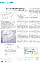
5 Overcurrent <strong>Protection</strong> / <strong>7SJ63</strong>Application5The <strong>SIPROTEC</strong> 4 <strong>7SJ63</strong> unit is a numericalprotection relay that also performs controland monitoring functions and therefore supportsthe user in cost-effective power systemmanagement, and ensures reliable supply ofelectric power to the customers. Local operationhas been designed according to ergonomiccriteria. A large, easy-to-read graphicdisplay was a major design aim.ControlThe integrated control function permits controlof disconnect devices (electrically operated/motorizedswitches) or circuit-breakersvia the integrated operator panel, binary inputs,DIGSI 4 or the control and protectionsystem (e.g. SICAM). The present status (orposition) of the primary equipment can bedisplayed. <strong>7SJ63</strong> supports substations withsingle and duplicate busbars. The number ofelements that can be controlled (usually 1 to5) is only restricted by the number of inputsand outputs available. A full range of commandprocessing functions is provided.Programmable logicThe integrated logic characteristics (CFC)allow the user to implement their own functionsfor automation of switchgear (interlocking)or a substation via a graphic userinterface. The user can also generate userdefinedmessages.5/118Line protectionThe <strong>7SJ63</strong> units can be used for line protectionof high and medium-voltage networkswith earthed (grounded), low-resistanceearthed, isolated or compensated neutralpoint.Motor protectionWhen protecting motors, the <strong>7SJ63</strong> relays aresuitable for asynchronous machines of allsizes.Transformer protectionThe <strong>7SJ63</strong> units perform all functions ofbackup protection supplementary to transformerdifferential protection. The inrushsuppression effectively prevents tripping byinrush currents.The high-impedance restricted earth-faultprotection detects short-circuits and insulationfaults on the transformer.Backup protectionThe relays can be used universally for backupprotection.Metering valuesExtensive measured values, limit values andmetering values permit improved systemsmanagement.Fig. 5/105 Function diagram<strong>Siemens</strong> SIP · 2006
5 Overcurrent <strong>Protection</strong> / <strong>7SJ63</strong>ApplicationANSI No. IEC <strong>Protection</strong> functions50, 50N I>, I>>I E>, I E>>Definite-time overcurrent protection (phase/neutral)51, 51N Ip, I Ep Inverse-time overcurrent protection (phase/neutral)67, 67N I dir>, I dir>>, I pdirI Edir>, I Edir>>, I Ep dir67Ns/50Ns I EE>,I EE>>, I EEpDirectional time-overcurrent protection (definite/inverse, phase/neutral),Directional comparison protectionDirectional/non-directional sensitive earth-fault detection– Cold load pick-up (dynamic setting change)59N/64 V E/V 0> Displacement voltage, zero-sequence voltage– I IE> Intermittent earth fault87N50BFHigh-impedance restricted earth-fault protectionBreaker failure protection579 Auto-reclosure46 I 2> Phase-balance current protection (negative-sequence protection)47 V 2>, phase seq. Unbalance-voltage protection and/or phase-sequence monitoring49 ϑ> Thermal overload protection48 Starting time supervision14 Locked rotor protection66/86 Restart inhibit37 I< Undercurrent monitoring38 Temperature monitoring via external device (RTD-box)e.g. bearing temperature monitoring27, 59 V Undervoltage/overvoltage protection81O/U f>, f< Overfrequency/underfrequency protection21FLFault locator<strong>Siemens</strong> SIP · 20065/119
5 Overcurrent <strong>Protection</strong> / <strong>7SJ63</strong>ConstructionConnection techniquesand housing with many advantages1/2 and 1/1-rack sizes5These are the available housing widths ofthe <strong>7SJ63</strong> relays, referred to a 19” moduleframe system. This means that previousmodels can always be replaced. The heightis a uniform 244 mm for flush-mountinghousings and 266 mm for surface-mountinghousings for all housing widths. All cablescan be connected with or without ringlugs. Plug-in terminals are available as anoption.It is thus possible to employ prefabricatedcable harnesses. In the case of surfacemounting on a panel, the connection terminalsare located above and below in theform of screw-type terminals. The communicationinterfaces are located in a slopedcase at the top and bottom of the housing.The housing can also be supplied optionallywith a detached operator panel (refer toFig. 5/108), or without operator panel, inorder to allow optimum operation for alltypes of applications.Fig. 5/106Flush-mounting housingwith screw-type terminalsLSP2174-afp.tifFig. 5/107Rear view of flush-mounting housingwith covered connection terminals and wiringsLSP2166-afp.tifLSP2196-afp.epsFig. 5/108Housing with plug-in terminals and detached operator panelLSP2219-afpen.epsLSP2237-afp.tifFig. 5/110Communication interfaces in asloped case in a surface-mountinghousingFig. 5/109Surface-mounting housingwith screw-type terminals5/120<strong>Siemens</strong> SIP · 2006
5 Overcurrent <strong>Protection</strong> / <strong>7SJ63</strong><strong>Protection</strong> functionsTime-overcurrent protection(ANSI 50, 50N, 51, 51N)This function is based on the phase-selectivemeasurement of the three phase currents andthe earth current (four transformers). Twodefinite-time overcurrent protection elements(DMT) exist both for the phases andfor the earth. The current threshold and thedelay time can be set within a wide range.In addition, inverse-time overcurrentprotection characteristics (IDMTL) can beactivated.Fig. 5/111Definite-time overcurrent protectionFig. 5/112Inverse-time overcurrent protection5Available inverse-time characteristicsCharacteristics acc. to ANSI/IEEE IEC 60255-3Inverse • •Short inverse•Long inverse • •Moderately inverse•Very inverse • •Extremely inverse • •Reset characteristicsFor easier time coordination with electromechanicalrelays, reset characteristicsaccording to ANSI C37.112 andIEC 60255-3 / BS 142 standards are applied.When using the reset characteristic (diskemulation), a reset process is initiated afterthe fault current has disappeared. This resetprocess corresponds to the reverse movementof the Ferraris disk of an electromechanicalrelay (thus: disk emulation).User-definable characteristicsInstead of the predefined time characteristicsaccording to ANSI, tripping characteristicscan be defined by the user for phase andearth units separately. Up to 20 current/time value pairs may be programmed. Theyare set as pairs of numbers or graphically inDIGSI 4.Inrush restraintThe relay features second harmonic restraint.If the second harmonic is detected duringtransformer energization, pickup of non-directionaland directional normal elementsare blocked.Cold load pickup/dynamic setting changeFor directional and non-directional timeovercurrentprotection functions the initiationthresholds and tripping times can beswitched via binary inputs or by time control.<strong>Siemens</strong> SIP · 20065/121
5 Overcurrent <strong>Protection</strong> / <strong>7SJ63</strong>5<strong>Protection</strong> functionsDirectional time-overcurrent protection(ANSI 67, 67N)Directional phase and earth protection areseparate functions. They operate in parallelto the non-directional overcurrent elements.Their pickup values and delay times can beset separately. Definite-time and inverse-timecharacteristic is offered. The tripping characteristiccan be rotated about ± 180 degrees.By means of voltage memory, directionalitycan be determined reliably even for close-in(local) faults. If the switching device closesonto a fault and the voltage is too low to determinedirection, directio- nality (directionaldecision) is made with voltage fromthe voltage memory. If no voltage exists inthe memory, tripping occurs according tothe coordination schedule.For earth protection, users can choosewhether the direction is to be determined viazero-sequence system or negative-sequencesystem quantities (selectable). Using negative-sequencevariables can be advantageousin cases where the zero voltage tends to bevery low due to unfavorable zero-sequenceimpedances.Fig. 5/113Directional characteristic of thedirectional time-overcurrentprotectionDirectional comparison protection(cross-coupling)It is used for selective protection of sectionsfed from two sources with instantaneoustripping, i.e. without the disadvantage oftime coordination. The directional comparisonprotection is suitable if the distances betweenthe protection stations are not significantand pilot wires are available for signaltransmission. In addition to the directionalcomparison protection, the directional coordinatedtime-overcurrent protection is usedfor complete selective backup protection. Ifoperated in a closed-circuit connection, aninterruption of the transmission line is detected.(Sensitive) directional earth-fault detection(ANSI 64, 67Ns, 67N)For isolated-neutral and compensated networks,the direction of power flow in the zerosequence is calculated from the zero-sequencecurrent I 0 and zero-sequence voltage V 0.For networks with an isolated neutral, the reactivecurrent component is evaluated; forcompensated networks, the active currentcomponent or residual resistive current isevaluated. For special network conditions,5/122e.g. high-resistance earthed networks withohmic-capacitive earth-fault current orlow-resistance earthed networks withohmic-inductive current, the tripping characteristicscan be rotated approximately± 45 degrees.Two modes of earth-fault direction detectioncan be implemented: tripping or “signallingonly mode”.It has the following functions:• TRIP via the displacement voltage V E.• Two instantaneous elements or oneinstantaneous plus one user-definedcharacteristic.• Each element can be set in forward,reverse, or non-directional.• The function can also be operated in theinsensitive mode as an additionalshort-circuit protection.Fig. 5/114Directional determination usingcosine measurements forcompensated networks(Sensitive) earth-fault detection(ANSI 50Ns, 51Ns / 50N, 51N)For high-resistance earthed networks, a sensitiveinput transformer is connected to aphase-balance neutral current transformer(also called core-balance CT).The function can also be operated in theinsensitive mode as an additional shortcircuitprotection.<strong>Siemens</strong> SIP · 2006
5 Overcurrent <strong>Protection</strong> / <strong>7SJ63</strong><strong>Protection</strong> functionsIntermittent earth-fault protectionIntermittent (re-striking) faults occur due toinsulationweaknessesincablesorasaresultof water penetrating cable joints. Such faultseither simply cease at some stage or developinto lasting short-circuits. During intermittentactivity, however, star-point resistors innetworks that are impedance-earthed mayundergo thermal overloading. The normalearth-fault protection cannot reliably detectand interrupt the current pulses, some ofwhich can be very brief.The selectivity required with intermittentearth faults is achieved by summating theduration of the individual pulses and bytriggering when a (settable) summed time isreached. The response threshold I IE>evaluatesthe r.m.s. value, referred to one systemsperiod.Phase-balance current protection (ANSI 46)(Negative-sequence protection)In line protection, the two-element phasebalancecurrent/negative-sequence protectionpermits detection on the high side ofhigh-resistance phase-to-phase faults andphase-to-earth faults that are on the low sideof a transformer (e.g. with the switch groupDy 5). This provides backup protection forhigh-resistance faults beyond the transformer.Breaker failure protection (ANSI 50BF)If a faulted portion of the electrical circuit isnot disconnected upon issuance of a tripcommand, another command can be initiatedusing the breaker failure protectionwhich operates the circuit-breaker, e.g. of anupstream (higher-level) protection relay.Breaker failure is detected if, after a trip command,current is still flowing in the faultedcircuit. As an option, it is possible to makeuse of the circuit-breaker position indication.High-impedance restricted earth-fault protection(ANSI 87N)The high-impedance measurement principleis an uncomplicated and sensitive methodfor detecting earth faults, especially on transformers.It can also be applied to motors,generators and reactors when these are operatedon an earthed network.When the high-impedance measurementprinciple is applied, all current transformersin the protected area are connected in parallelandoperatedononecommonresistorofrelativelyhigh R whose voltage is measured (seeFig. 5/115). In the case of 7SJ6 units, the voltageis measured by detecting the currentthrough the (external) resistor R at the sensitivecurrent measurement input I EE.Thevaristor V serves to limit the voltage in theevent of an internal fault. It cuts off the highmomentary voltage spikes occurring at transformersaturation. At the same time, this resultsin smoothing of the voltage without anynoteworthy reduction of the average value.If no faults have occurred and in the event ofexternal faults, the system is at equilibrium,and the voltage through the resistor is approximatelyzero. In the event of internalfaults, an imbalance occurs which leads to avoltage and a current flow through the resistorR.The current transformers must be of thesame type and must at least offer a separatecore for the high-impedance restrictedearth-fault protection. They must in particularhave the same transformation ratio andan approximately identical knee-point voltage.They should also demonstrate only minimalmeasuring errors.Auto-reclosure (ANSI 79)Multiple reclosures can be defined by theuser and lockout will occur if a fault is presentafter the last reclosure. The followingfunctions are possible:• 3-pole ARC for all types of faults• Separate settings for phase and earth faults• Multiple ARC, one rapid auto-reclosure(RAR) and up to nine delayedauto-reclosures (DAR)• Starting of the ARC depends on the tripcommand selection (e.g. 46, 50, 51, 67)• Blocking option of the ARC via binaryinputs• ARC can be initiated externally or via CFC• The directional and non-directional elementscan either be blocked or operatednon-delayed depending on the autoreclosurecycle• Dynamic setting change of the directionaland non-directional elements can be activateddepending on the ready ARFig. 5/115High-impedance restricted earthfaultprotectionThermal overload protection (ANSI 49)For protecting cables and transformers,an overload protection with an integratedpre-warning element for temperature andcurrent can be applied. The temperature iscalculated using a thermal homogeneousbodymodel (according to IEC 60255-8),which takes account both of the energy enteringthe equipment and the energy losses.The calculated temperature is constantly adjustedaccordingly. Thus, account is taken ofthe previous load and the load fluctuations.For thermal protection of motors (especiallythe stator) a further time constant can be setso that the thermal ratios can be detectedcorrectly while the motor is rotating andwhen it is stopped. The ambient temperatureor the temperature of the coolant can be detectedserially via an external temperaturemonitoring box (resistance-temperature detectorbox, also called RTD- box). The thermalreplica of the overload function is automaticallyadapted to the ambient conditions.If there is no RTD-box it is assumed that theambient temperatures are constant.Settable dropout delay timesIf the devices are used in parallel with electromechanicalrelays in networks with intermittentfaults, the long dropout times of theelectromechanical devices (several hundredmilliseconds) can lead to problems in termsof time grading. Clean time grading is onlypossible if the dropout time is approximatelythe same. This is why the parameter of dropouttimes can be defined for certain functionssuch as time-overcurrent protection, earthshort-circuit and phase-balance current protection.5<strong>Siemens</strong> SIP · 20065/123
5 Overcurrent <strong>Protection</strong> / <strong>7SJ63</strong>5<strong>Protection</strong> functionsn Motor protectionRestart inhibit (ANSI 66/86)If a motor is started up too many times insuccession, the rotor can be subject to thermaloverload, especially the upper edges ofthebars.Therotortemperatureiscalculatedfrom the stator current. The reclosing lockoutonly permits start-up of the motor if therotor has sufficient thermal reserves for acomplete start-up (see Fig. 5/116).Emergency start-upThis function disables the reclosing lockoutvia a binary input by storing the state of thethermal replica as long as the binary input isactive.Itisalsopossibletoresetthethermalreplica to zero.Fig. 5/116Temperature monitoring (ANSI 38)Up to two temperature monitoring boxeswith a total of 12 measuring sensors can beused for temperature monitoring and detectionby the protection relay. The thermal statusof motors, generators and transformerscan be monitored with this device. Additionally,the temperature of the bearings of rotatingmachines are monitored for limit valueviolation. The temperatures are being measuredwith the help of temperature detectorsat various locations of the device to be protected.This data is transmitted to the protectionrelay via one or two temperature monitoringboxes (see “Accessories”, page 5/149).Starting time supervision (ANSI 48/14)Starting time supervision protects the motoragainst long unwanted start-ups that mightoccur in the event of excessive load torque orexcessive voltage drops within the motor, orif the rotor is locked. Rotor temperature iscalculated from measured stator current. Thetripping time is calculated according to thefollowing equation:for I > I MOTOR STARTt = ⎛ I A ⎞⎜ ⎟ ⋅ T⎝ I ⎠I5/1242I MOTOR STARTtI AT AA= Actual current flowing= Pickup current to detect a motorstart= Tripping time= Rated motor starting current= Tripping time at rated motorstarting current1) The 45 to 55, 55 to 65 Hz range is availablefor f N= 50/60 Hz.If the trip time is rated according to theabove formula, even a prolonged start-upand reduced voltage (and reduced start-upcurrent) will be evaluated correctly. The trippingtime is inverse (current dependent).A binary signal is set by a speed sensor to detecta blocked rotor. An instantaneous trippingis effected.Phase-balance current protection (ANSI 46)(Negative-sequence protection)The negative-sequence / phase-balance currentprotection detects a phase failure or loadunbalance due to network asymmetry andprotects the rotor from impermissible temperaturerise.Undercurrent monitoring (ANSI 37)With this function, a sudden drop in current,which can occur due to a reduced motorload, is detected. This may be due to shaftbreakage, no-load operation of pumps or fanfailure.n Voltage protectionOvervoltage protection (ANSI 59)The two-element overvoltage protection detectsunwanted network and machineovervoltage conditions. The function can operateeither with phase-to-phase voltage (default)or with the negative phase-sequencesystem voltage. Three-phase and single-phaseconnections are possible.Undervoltage protection (ANSI 27)The two-element undervoltage protectionprovides protection against dangerous voltagedrops (especially for electric machines).Applications include the isolation of generatorsor motors from the network to avoidundesired operating states and a possible lossof stability. Proper operating conditions ofelectrical machines are best evaluated withthe positive-sequence quantities. The protectionfunction is active over a wide frequencyrange (45 to 55, 55 to 65 Hz) 1) .Evenwhenfalling below this frequency range the functioncontinues to work, however, with agreater tolerance band.The function can operate either with the positivephase-sequence system voltage (default)or with the phase-to-phase voltages, and canbe monitored with a current criterion.Three-phase and single-phase connectionsare possible.Frequency protection (ANSI 81O/U)Frequency protection can be used for overfrequencyand underfrequency protection.Electric machines and parts of the system areprotected from unwanted speed deviations.Unwanted frequency changes in the networkcan be detected and the load can be removedat a specified frequency setting. Frequencyprotection can be used over a wide frequencyrange (45 to 55, 55 to 65 Hz) 1) .Therearefourelements (selectable as overfrequency orunderfrequency) and each element can bedelayed separately. Blocking of the frequencyprotection can be performed if using a binaryinput or by using an undervoltage element.<strong>Siemens</strong> SIP · 2006
5 Overcurrent <strong>Protection</strong> / <strong>7SJ63</strong><strong>Protection</strong> functions/FunctionsFault locator (ANSI 21FL)The fault locator specifies the distance to afault location in kilometers or miles or thereactance of a second fault operation.Circuit-breaker wear monitoringMethods for determining circuit-breakercontact wear or the remaining service life of acircuit-breaker (CB) allow CB maintenanceintervals to be aligned to their actual degreeof wear. The benefit lies in reduced maintenancecosts.There is no mathematically exact method ofcalculating the wear or the remaining servicelife of circuit-breakers that takes into accountthe arc-chamber's physical conditions whentheCBopens.Thisiswhyvariousmethodsofdetermining CB wear have evolved which reflectthe different operator philosophies. Todo justice to these, the devices offer severalmethods:• I•ΣI x , with x = 1... 3The devices additionally offer a new methodfor determining the remaining service life:• Two-point methodThe CB manufacturers double-logarithmicswitching cycle diagram (see Fig. 5/117) andthe breaking current at the time of contactopening serve as the basis for this method.After CB opening, the two-point method calculatesthe number of still possible switchingcycles. To this end, the two points P1 and P2only have to be set on the device. These arespecified in the CB's technical data.Allofthesemethodsarephase-selectiveandalimit value can be set in order to obtain analarm if the actual value falls below or exceedsthe limit value during determination ofthe remaining service life.Customized functions (ANSI 32, 51V, 55, etc.)Additional functions, which are not timecritical, can be implemented via the CFC usingmeasured values. Typical functions includereverse power, voltage controlledovercurrent, phase angle detection, and zerosequencevoltage detection.CommissioningCommissioning could hardly be easier and isfully supported by DIGSI 4. The status of thebinary inputs can be read individually andthe state of the binary outputs can be set individually.The operation of switching elements(circuit-breakers, disconnect devices)can be checked using the switching functionsof the bay controller. The analog measuredvalues are represented as wide-ranging operationalmeasured values. To prevent transmissionof information to the control centerduring maintenance, the bay controller communicationscan be disabled to prevent unnecessarydata from being transmitted. Duringcommissioning, all indications with testmarking for test purposes can be connectedto a control and protection system.Test operationDuring commissioning, all indications canbe passed to an automatic control system fortest purposes.n Control and automatic functionsControlIn addition to the protection functions, the<strong>SIPROTEC</strong> 4 units also support all controland monitoring functions that are requiredfor operating medium-voltage or high-voltagesubstations.The main application is reliable control ofswitching and other processes.The status of primary equipment or auxiliarydevices can be obtained from auxiliary contactsand communicated to the <strong>7SJ63</strong> via binaryinputs. Therefore it is possible to detectand indicate both the OPEN and CLOSEDposition or a fault or intermediate circuit-breakeror auxiliary contact position.The switchgear or circuit-breaker can becontrolled via:– integrated operator panel– binary inputs– substation control and protection system– DIGSI 4Automation / user-defined logicWith integrated logic, the user can set, via agraphic interface (CFC), specific functionsfor the automation of switchgear or substation.Functions are activated via functionkeys, binary input or via communicationinterface.Fig. 5/117CB switching cycle diagramSwitching authoritySwitching authority is determined accordingto parameters, communication or by keyoperatedswitch (when available).If a source is set to “LOCAL”, only localswitching operations are possible. The followingsequence of switching authority is laiddown: “LOCAL”; DIGSI PC program,“REMOTE”.Key-operated switch<strong>7SJ63</strong> units are fitted with key-operatedswitch function for local/remote changeoverand changeover between interlocked switchingand test operation.Command processingAll the functionality of command processingis offered. This includes the processing of singleand double commands with or withoutfeedback, sophisticated monitoring of thecontrol hardware and software, checking ofthe external process, control actions usingfunctions such as runtime monitoring andautomatic command termination after output.Here are some typical applications:• Single and double commands using 1,1 plus 1 common or 2 trip contacts• User-definable bay interlocks• Operating sequences combining severalswitching operations such as control ofcircuit-breakers, disconnectors andearthing switches• Triggering of switching operations, indicationsor alarm by combination withexisting information51) The 45 to 55, 55 to 65 Hz range isavailable for f N= 50/60 Hz<strong>Siemens</strong> SIP · 20065/125
5 Overcurrent <strong>Protection</strong> / <strong>7SJ63</strong>5FunctionsMotor controlThe <strong>SIPROTEC</strong> 4 <strong>7SJ63</strong> with high performancerelays is well-suited for direct activationof the circuit-breaker, disconnector andearthing switch operating mechanisms inautomated substations.Interlocking of the individual switching devicestakes place with the aid of programmablelogic. Additional auxiliary relays can beeliminated. This results in less wiring and engineeringeffort.Assignment of feedback to commandThe positions of the circuit-breaker orswitching devices and transformer taps areacquired by feedback. These indication inputsare logically assigned to the correspondingcommand outputs. The unit can thereforedistinguish whether the indicationchange is a consequence of switching operationor whether it is a spontaneous change ofstate.Chatter disableChatter disable feature evaluates whether, ina configured period of time, the number ofstatus changes of indication input exceeds aspecified figure. If exceeded, the indicationinput is blocked for a certain period, so thatthe event list will not record excessive operations.Fig. 5/118Typical wiring for <strong>7SJ63</strong>2 motor direct control (simplified representation without fuses)Binary output BO4 and BO5 are interlocked so that only one set of contacts are closed at a time.Indication filtering and delayBinary indications can be filtered or delayed.Filtering serves to suppress brief changes inpotential at the indication input. The indicationis passed on only if the indication voltageis still present after a set period of time. Inthe event of indication delay, there is a waitfor a preset time. The information is passedon only if the indication voltage is still presentafter this time.Indication derivationA further indication (or a command) can bederived from an existing indication. Groupindications can also be formed. The volumeof information to the system interface canthus be reduced and restricted to the mostimportant signals.Fig. 5/119Example: Single busbar with circuit-breaker andmotor-controlled three-position switchFig. 5/120Example: Circuit-breaker interlocking5/126<strong>Siemens</strong> SIP · 2006
5 Overcurrent <strong>Protection</strong> / <strong>7SJ63</strong>FunctionsMeasured valuesThe r.m.s. values are calculated from the acquiredcurrent and voltage along with thepower factor, frequency, active and reactivepower. The following functions are availablefor measured value processing:• Currents I L1 , I L2 , I L3 , I E , I EE (67Ns)• Voltages V L1 , V L2 , V L3 , V L1L2 , V L2L3 , V L3L1• Symmetrical componentsI 1 , I 2 ,3I 0 ; V 1 , V 2 , V 0• Power Watts, Vars, VA/P, Q, S(P, Q: total and phase-selective)• Power factor (cos ϕ)(total and phase-selective)• Frequency• Energy ± kWh, ± kVarh, forward andreverse power flow• Mean as well as minimum and maximumcurrent and voltage values• Operating hours counter• Mean operating temperature of overloadfunction• Limit value monitoringLimit values are monitored using programmablelogicintheCFC.Commandscan be derived from this limit value indication.• Zero suppressionIn a certain range of very low measuredvalues, the value is set to zero to suppressinterference.Metered valuesFor internal metering, the unit can calculatean energy metered value from the measuredcurrent and voltage values. If an external meterwith a metering pulse output is available,the <strong>SIPROTEC</strong> 4 unit can obtain and processmetering pulses via an indication input.The metered values can be displayed andpassed on to a control center as an accumulationwith reset. A distinction is made betweenforward, reverse, active and reactiveenergy.Measuring transducers• Characteristic with kneeFor measuring transducers it sometimesmakes sense to extend a small range of theinput value, e.g. for the frequency that isonly relevant in the range 45 to 55, 55 to65 Hz. This can be achieved by using aknee characteristic.• Live-zero monitoring4 - 20 mA circuits are monitored foropen-circuit detection.LSP2078-afp.eps5Switchgear cubiclesfor high/medium voltageAll units are designed specifically to meetthe requirements of high/medium-voltageapplications.In general, no separate measuring instruments(e.g. for current, voltage, frequencymeasuring transducer ...) or additionalcontrol components are necessary.Fig. 5/121NX PLUS panel (gas-insulated)<strong>Siemens</strong> SIP · 20065/127
5 Overcurrent <strong>Protection</strong> / <strong>7SJ63</strong>CommunicationIn terms of communication, the units offersubstantial flexibility in the context of connectionto industrial and power automationstandards. Communication can be extendedor added on thanks to modules for retrofittingon which the common protocols run.Therefore, also in the future it will be possibleto optimally integrate units into the changingcommunication infrastructure, for examplein Ethernet networks (which will also be usedincreasingly in the power supply sector in theyears to come).System interface protocols (retrofittable)IEC 61850 protocolAs of mid-2004, the Ethernet-basedIEC 61850 protocol is the worldwide standardfor protection and control systems usedby power supply corporations. <strong>Siemens</strong> is thefirst manufacturer to support this standard.By means of this protocol, information canalso be exchanged directly between bay unitsso as to set up simple masterless systems forbay and system interlocking. Access to theunits via the Ethernet bus will also be possiblewith DIGSI.5Serial front interfaceThere is a serial RS232 interface on the frontof all the units. All of the unit’s functions canbe set on a PC by means of the DIGSI 4 protectionoperation program. Commissioningtools and fault analysis are also built into theprogram and are available through this interface.IEC 60870-5-103 protocolThe IEC 60870-5-103 protocol is an internationalstandard for the transmission of protectivedata and fault recordings. All messagesfrom the unit and also controlcommands can be transferred by means ofpublished, <strong>Siemens</strong>-specific extensions to theprotocol.Fig. 5/122IEC 60870-5-103: Radial fiber-optic connectionRear-mounted interfaces 1)A number of communication modules suitablefor various applications can be fitted inthe rear of the flush-mounting housing. Inthe flush-mounting housing, the modulescan be easily replaced by the user.The interface modules support the followingapplications:• Time synchronization interfaceAll units feature a permanently integratedelectrical time synchronization interface.It can be used to feed timing telegrams inIRIG-B or DCF77 format into the unitsvia time synchronization receivers.• System interfaceCommunication with a central controlsystem takes place through this interface.Radial or ring type station bus topologiescan be configured depending on the choseninterface. Furthermore, the units canexchange data through this interface viaEthernet and IEC 61850 protocol and canalso be operated by DIGSI.• Service interfaceThe service interface was conceived for remoteaccess to a number of protectionunits via DIGSI. On all units, it can be anelectrical RS232/RS485 or an optical interface.For special applications, a maximumof two temperature monitoring boxes(RTD-box) can be connected to this interfaceas an alternative.PROFIBUS-FMSPROFIBUS-FMS is an internationally standardizedcommunication system (EN 50170)for efficient performance of communicationtasks in the bay area. <strong>SIPROTEC</strong> 4 units use aprofile specially optimized for protection andcontrol requirements. DIGSI can also workon the basis of PROFIBUS-FMS. The unitsare linked to a SICAM automation system.PROFIBUS-DP protocolPROFIBUS-DP is the most widespread protocolin industrial automation. ViaPROFIBUS-DP, <strong>SIPROTEC</strong> units make theirinformation available to a SIMATIC controlleror, in the control direction, receive commandsfrom a central SIMATIC. Measuredvalues can also be transferred.MODBUS RTU protocolThis uncomplicated, serial protocol is mainlyused in industry and by power supply corporations,and is supported by a number of unitmanufacturers. <strong>SIPROTEC</strong> units function asMODBUS slaves, making their informationavailable to a master or receiving informationfrom it. A time-stamped event list is available.Fig. 5/123PROFIBUS: Fiber-optic double ring circuit1) For units in panel surface-mounting housingsplease refer to note on page 5/148.Fig. 5/124Bus structure for station bus with Ethernet andIEC 61850, fiber-optic ring5/128<strong>Siemens</strong> SIP · 2006
5 Overcurrent <strong>Protection</strong> / <strong>7SJ63</strong>CommunicationDNP 3.0 protocolPower supply corporations use the serialDNP 3.0 (Distributed Network Protocol) forthe station and network control levels.<strong>SIPROTEC</strong> units function as DNP slaves,supplying their information to a master systemor receiving information from it.System solutions for protection and stationcontrolTogether with the SICAM power automationsystem, <strong>SIPROTEC</strong> 4 can be used withPROFIBUS-FMS. Over the low-cost electricalRS485 bus, or interference-free via theoptical double ring, the units exchange informationwith the control system.Units featuring IEC 60870-5-103 interfacescan be connected to SICAM in parallel viathe RS485 bus or radially by fiber-optic link.Through this interface, the system is openfor the connection of units of other manufacturers(see Fig. 5/122).Because of the standardized interfaces,<strong>SIPROTEC</strong> units can also be integrated intosystems of other manufacturers or inSIMATIC. Electrical RS485 or optical interfacesare available. The optimum physicaldata transfer medium can be chosen thanksto opto-electrical converters. Thus, theRS485 bus allows low-cost wiring in the cubiclesand an interference-free optical connectionto the master can be established.For IEC 61850, an interoperable system solutionis offered with SICAM PAS. Via the100 Mbits/s Ethernet bus, the units are linkedwith PAS electrically or optically to the stationPC. The interface is standardized, thusalso enabling direct connection of units ofother manufacturers to the Ethernet bus.With IEC 61850, however, the units can alsobe used in other manufacturers’ systems(see Fig. 5/124).Fig. 5/125System solution/communicationFig. 5/126Optical Ethernet communication modulefor IEC 61850 with integrated Ethernet-switchLSP2810.tif5<strong>Siemens</strong> SIP · 20065/129
5 Overcurrent <strong>Protection</strong> / <strong>7SJ63</strong>Typical connectionsn Connection of currentand voltage transformersStandard connectionFor earthed networks, the earth current isobtained from the phase currents by theresidual current circuit.5Fig. 5/127Residual currentcircuit without directionalelementFig. 5/128Sensitive earthcurrent detectionwithout directionalelementFig. 5/129Residual currentcircuit with directionalelement5/130<strong>Siemens</strong> SIP · 2006
5 Overcurrent <strong>Protection</strong> / <strong>7SJ63</strong>Typical connectionsConnection for compensated networksThe figure shows the connection of twophase-to-earth voltages and the V Evoltage ofthe open delta winding and a phasebalanceneutral current transformer for theearth current. This connection maintainsmaximum precision for directional earthfaultdetection and must be used in compensatednetworks.Figure 5/130 shows sensitive directionalearth-fault detection.Fig. 5/130Sensitive directionalearth-fault detectionwith directionalelement for phases5Fig. 5/131Sensitive directionalearth-fault detectionConnection for isolated-neutralor compensated networks onlyIf directional earth-fault protection is notused, the connection can be made with onlytwo phase current transformers. Directionalphase short-circuit protection can beachieved by using only two primary transformers.Fig. 5/132Isolated-neutral orcompensatednetworks<strong>Siemens</strong> SIP · 20065/131
5 Overcurrent <strong>Protection</strong> / <strong>7SJ63</strong>Typical applicationsOverview of connection types5Type of network Function Current connection Voltage connection(Low-resistance) earthed network Time-overcurrent protectionphase/earth non-directionalResidual circuit, with 3 phase-currenttransformers required, phase-balanceneutral current transformer possible-(Low-resistance) earthed networks Sensitive earth-fault protection Phase-balance neutral currenttransformers requiredIsolated or compensated networks(Low-resistance) earthed networksIsolated or compensated networks(Low-resistance) earthed networksIsolated networksCompensated networksTime-overcurrent protectionphases non-directionalTime-overcurrent protectionphases directionalTime-overcurrent protectionphases directionalTime-overcurrent protectionearth directionalSensitive earth-faultprotectionSensitive earth-fault protectioncos ϕ measurementResidual circuit, with 3 or 2 phasecurrent transformers possibleResidual circuit, with 3 phase-currenttransformers possibleResidual circuit, with 3 or 2 phasecurrenttransformers possibleResidual circuit, with 3 phase-currenttransformers required, phase-balanceneutral current transformers possibleResidual circuit, if earth current>0.05I N on secondary side, otherwisephase-balance neutral currenttransformers requiredPhase-balance neutral currenttransformers required--Phase-to-earth connection orphase-to-phase connectionPhase-to-earth connection orphase-to-phase connectionPhase-to-earth connection required3 times phase-to-earth connection orphase-to-earth connection with opendelta windingPhase-to-earth connection with opendelta winding requiredn Connection of circuit-breakerUndervoltage releasesUndervoltage releases are used for automatictripping of high-voltage motors.Example:DC supply voltage of control system fails andmanual electric tripping is no longer possible.Automatic tripping takes place when voltageacross the coil drops below the trip limit. InFig. 5/133, tripping occurs due to failure ofDC supply voltage, by automatic opening ofthe live status contact upon failure of theprotection unit or by short-circuiting the tripcoil in event of a network fault.Fig. 5/133 Undervoltage release with make contact ( 50, 51)5/132<strong>Siemens</strong> SIP · 2006
5 Overcurrent <strong>Protection</strong> / <strong>7SJ63</strong>Typical applicationsIn Fig. 5/134 tripping is by failure of auxiliaryvoltage and by interruption of tripping circuitin the event of network failure. Uponfailure of the protection unit, the trippingcircuit is also interrupted, since contact heldby internal logic drops back into open position.Trip circuit supervision (ANSI 74TC)One or two binary inputs can be used formonitoring the circuit-breaker trip coil includingits incoming cables. An alarm signaloccurs whenever the circuit is interrupted.Lockout (ANSI 86)All binary outputs can be stored like LEDsand reset using the LED reset key. The lockoutstate is also stored in the event of supplyvoltage failure. Reclosure can only occur afterthe lockout state is reset.Fig. 5/134Undervoltage release with locking contact (trip signal 50 is inverted)5Fig. 5/135Trip circuit supervision with 2 binary inputsFig. 5/136Trip circuit supervision with 1 binary input<strong>Siemens</strong> SIP · 20065/133
5 Overcurrent <strong>Protection</strong> / <strong>7SJ63</strong>5Technical dataGeneral unit dataMeasuring circuitsSystem frequencyCurrent transformerRated current I nomOption: sensitive earth-fault CTPower consumptionat I nom =1Aat I nom =5Afor sensitive earth-fault CT at 1 AOverload capabilityThermal (effective)Dynamic (impulse current)Overload capability if equipped withsensitive earth-fault CTThermal (effective)Dynamic (impulse current)Voltage transformerRated voltage V nomPower consumption at V nom = 100 V50 / 60 Hz (settable)1 or 5 A (settable)I EE 110VDC≥ 20msatV>24VDCRated auxiliary voltage V aux AC 115 V 230 VPermissible tolerance AC 92 - 132 V 184 - 265 VPower consumption <strong>7SJ63</strong>1 <strong>7SJ63</strong>2<strong>7SJ63</strong>3QuiescentEnergizedBackup time duringloss/short-circuit ofauxiliary alternating voltageApprox.Approx.3W12 W≥ 200 ms5W18 W<strong>7SJ63</strong>5<strong>7SJ63</strong>67W20 W<strong>7SJ63</strong>5<strong>7SJ63</strong>67W23 WBinary inputs/indication inputsType <strong>7SJ63</strong>1 <strong>7SJ63</strong>2 <strong>7SJ63</strong>3 <strong>7SJ63</strong>5 <strong>7SJ63</strong>6Number (marshallable) 11 24 20 37 33Voltage range24 - 250 V DCPickup threshold modifiableby plug-in jumpersPickupthresholdDC 19VDC 88VDCFor rated control voltage DC 24/48/60/110/ 110/125/220/250 V DC125VDCPower consumptionenergized0.9 mA (independent of operating voltage)for BI 1…6 / 8…19 / 25…36;1.8 mA for BI 7 / 20…24 / 37Binary outputs/command outputsType <strong>7SJ63</strong>1 <strong>7SJ63</strong>2 <strong>7SJ63</strong>3 <strong>7SJ63</strong>5 <strong>7SJ63</strong>6Command/indicationrelay 8 11 11 14 14Contacts per command/ 1NO/formAindication relayLive status contactSwitching capacity MakeSwitching voltage1 NO / NC (jumper) / form A / B1000 W / VABreak 30 W / VA / 40 W resistive /25 W at L/R ≤ 50 ms≤ 250VDCPermissible current 5 A continuous,30 A for 0.5 s making current,2000 switching cyclesPower relay (for motor control)Type <strong>7SJ63</strong>1 <strong>7SJ63</strong>2<strong>7SJ63</strong>3<strong>7SJ63</strong>6<strong>7SJ63</strong>5Number 0 2 (4) 4 (8)Number of contacts/relay2 NO / form ASwitching capacity Make 1000 W / VA at 48 V … 250 V / 500 W at 24 VSwitching voltagePermissible currentBreak1000 W / VA at 48 V … 250 V / 500 W at 24 V≤ 250VDC5 A continuous,30 A for 0.5 s5/134<strong>Siemens</strong> SIP · 2006
5 Overcurrent <strong>Protection</strong> / <strong>7SJ63</strong>Technical dataElectrical testsSpecificationStandards IEC 60255ANSI C37.90, C37.90.1, C37.90.2,UL508Insulation testsStandardsIEC 60255-5; ANSI/IEEE C37.90.0Voltage test (100 % test)2.5 kV (r.m.s. value), 50/60 Hzall circuits except for auxiliaryvoltage and RS485/RS232 andtime synchronizationAuxiliary voltageCommunication portsand time synchronizationImpulse voltage test (type test)all circuits, except communicationports and time synchronization,class III3.5 kV DC500VACEMC tests for interference immunity; type tests5kV(peakvalue);1.2/50µs;0.5J3 positive and 3 negative impulsesat intervals of 5 sStandards IEC 60255-6; IEC 60255-22(product standard)EN 50082-2 (generic specification)DIN 57435 Part 303High-frequency testIEC 60255-22-1, class IIIand VDE 0435 Part 303, class IIIElectrostatic dischargeIEC 60255-22-2 class IVand EN 61000-4-2, class IVIrradiation with radio-frequencyfield, non-modulatedIEC 60255-22-3 (Report) class IIIIrradiation with radio-frequencyfield, amplitude-modulatedIEC 61000-4-3; class III2.5kV(peakvalue);1MHz;τ =15 ms;400 surges per s; test duration 2 s8kVcontactdischarge;15 kV air gap discharge;both polarities; 150 pF; R i = 330 Ω10 V/m; 27 to 500 MHz10 V/m, 80 to 1000 MHz;AM 80 %; 1 kHzIrradiation with radio-frequency 10 V/m, 900 MHz; repetitionfield, pulse-modulatedrate 200 Hz, on duration 50 %IEC 61000-4-3/ENV 50204; class IIIFast transient interference/burst 4 kV; 5/50 ns; 5 kHz;IEC 60255-22-4 and IEC 61000-4-4, burst length = 15 ms;class IVrepetition rate 300 ms; both polarities;R i =50Ω; test duration 1 minHigh-energy surge voltages(Surge)IEC 61000-4-5; class IIIAuxiliary voltageBinary inputs/outputsLine-conducted HF,amplitude-modulatedIEC 61000-4-6, class IIIPower frequency magnetic fieldIEC 61000-4-8, class IVIEC 60255-6Oscillatory surge withstandcapabilityANSI/IEEE C37.90.1From circuit to circuit: 2 kV; 12 Ω;9µFacross contacts: 1 kV; 2 Ω ;18 µFFrom circuit to circuit: 2 kV; 42 Ω;0.5µFacross contacts: 1 kV; 42 Ω;0.5µF10 V; 150 kHz to 80 MHz;AM 80 %; 1 kHz30 A/m; 50 Hz, continuous300 A/m; 50 Hz, 3 s0.5 mT, 50 Hz2.5to3kV(peakvalue),1to1.5MHzdamped wave; 50 surges per s;duration 2 s, R i = 150 to 200 ΩFast transient surge withstandcapability ANSI/IEEE C37.90.1Radiated electromagneticinterferenceANSI/IEEE C37.90.2Damped waveIEC 60694 / IEC 61000-4-12EMC tests for interference emission; type testsStandardConducted interferencesonly auxiliary voltage IEC/CISPR 22Radio interference field strengthIEC/CISPR 11Units with a detached operator panelmust be installed in a metal cubicleto maintain limit class B4 to 5 kV; 10/150 ns; 50 surges per sboth polarities; duration 2 s, R i =80Ω35 V/m; 25 to 1000 MHz;amplitude and pulse-modulated2.5kV(peakvalue,polarityalternating)100 kHz, 1 MHz, 10 and 50 MHz,R i = 200 ΩEN 50081-* (generic specification)150 kHz to 30 MHzLimit class B30 to 1000 MHzLimit class BMechanical stress testsVibration, shock stress and seismic vibrationDuringoperationStandards IEC 60255-21 and IEC 60068-2VibrationIEC 60255-21-1, class 2IEC 60068-2-6ShockIEC 60255-21-2, class 1IEC 60068-2-27Seismic vibrationIEC 60255-21-3, class 1IEC 60068-3-3Sinusoidal10 to 60 Hz; +/- 0.075 mm amplitude;60 to 150 Hz; 1 g accelerationfrequency sweep 1 octave/min20 cycles in 3 perpendicular axesSemi-sinusoidalAcceleration 5 g, duration 11 ms;3 shocks in both directions of 3 axesSinusoidal1to8Hz:±3.5mmamplitude(horizontal axis)1to8Hz:±1.5mmamplitude(vertical axis)8to35Hz:1g acceleration(horizontal axis)8to35Hz:0.5g acceleration(vertical axis)Frequency sweep 1 octave/min1 cycle in 3 perpendicular axesDuringtransportationStandards IEC 60255-21 and IEC 60068-2VibrationIEC 60255-21-1, class 2IEC 60068-2-6ShockIEC 60255-21-2, Class 1IEC 60068-2-27Continuous shockIEC 60255-21-2, class 1IEC 60068-2-29Sinusoidal5to8Hz:±7.5mmamplitude;8 to 150 Hz; 2 g acceleration,frequency sweep 1 octave/min20 cycles in 3 perpendicular axesSemi-sinusoidalAcceleration 15 g, duration 11 ms3 shocks in both directions of 3 axesSemi-sinusoidalAcceleration 10 g, duration 16 ms1000 shocks in both directionsof 3 axes5<strong>Siemens</strong> SIP · 20065/135
5 Overcurrent <strong>Protection</strong> / <strong>7SJ63</strong>Technical dataClimatic stress testsSystem interface (rear of unit)TemperaturesIEC 60870-5-103 protocolType-tested acc. to IEC 60068-2-1and -2, test Bd, for 16 h-25 °C to +85 °C /-13 °F to +185 °FIsolated interface for data transferto a control centerPort BTemporarily permissible operatingtemperature, tested for 96 h-20 °C to +70 °C /-4 °F to +158 °FTransmission rateSetting as supplied: 9600 baud,min. 9600 baud, max. 19200 baud5Recommended permanent operatingtemperature acc. to IEC60255-6(Legibility of display may be impairedabove +55 °C /+131 °F)– Limiting temperature duringpermanent storage– Limiting temperature duringtransportHumidityPermissible humidityIt is recommended to arrange theunits in such a way that they arenot exposed to direct sunlight orpronounced temperature changesthat could cause condensation.Unit designHousingDimensionsWeight in kgSurface-mounting housingFlush-mounting housingHousing for detached operatorpanelDetached operator panelDegree of protectionacc. to EN 60529Surface-mounting housingFlush-mounting housingOperator safety-5 °C to +55 °C /+25 °F to +131 °F-25 °C to +55 °C /-13 °F to +131 °F-25 °C to +70 °C /-13 °F to +158 °FAnnual average 75 % relative humidity;on 56 days a year up to 95 % relativehumidity; condensation notpermissible!7XP20See dimension drawings, part 16 ofthis catalogHousing width 1/2 Housing width 1/17.5 156.5 138.0 152.5 2.5IP 51Front: IP 51, rear: IP 20;IP 2x with coverRS232/RS485ConnectionFor flush-mounting housing/surface-mounting housing withdetached operator panelFor surface-mounting housingwith two-tier terminal on thetop/bottom partDistance RS232Distance RS485Test voltageFiber opticConnection fiber-optic cableFor flush-mounting housing/surface-mounting housing withdetached operator panelFor surface-mounting housingwith two-tier terminal on thetop/bottom partOptical wavelengthPermissible path attenuationDistanceIEC 61850 protocolIsolated interface for data transfer:-toacontrolcenter-withDIGSI- between <strong>SIPROTEC</strong> 4 relaysTransmission rateEthernet, electricalMounting location “B”At the bottom part of the housing:shielded data cableMax. 15 m/49 ftMax. 1 km/3300 ft500VACagainstearthIntegrated ST connector for fiber-opticconnectionMounting location “B”At the bottom part of the housing820 nmMax. 8 dB, for glass fiber 62.5/125 µmMax. 1.5 km/0.9 milesPort B, 100 Base T acc. to IEEE802.3100 MbitSerial interfacesOperating interface (front of unit)ConnectionNon-isolated, RS232; front panel,9-pin subminiature connectorTransmission ratemin. 4800 baud, max. 115200 baudService/modem interface (rear of unit)Isolated interface for data transferTransmission rateRS232/RS485ConnectionFor flush-mounting housing/surface-mounting housing withdetached operator panelFor surface-mounting housingwith two-tier terminal at thetop/bottom partDistance RS232Distance RS485Test voltagePort C: DIGSI 4/modem/RTD-boxSetting as supplied 38400 baudmin. 4800 baud, max. 115200 baud9-pin subminiature connector,mounting location “C”At the bottom part of the housing:shielded data cable15 m /49.2 ftMax. 1 km/3300 ft500VACagainstearthConnectionFor flush-mounting housing/surface-mounting housing withdetached operator panelDistanceTest voltageEthernet, opticalConnectionFor flush-mounting housing/surface-mounting housing withdetached operator panelOptical wavelengthDistancePROFIBUS-FMS/DPIsolated interface for data transferto a control centerTransmission rateTwo RJ45 connectorsMounting location "B"Max. 20 m / 65.6 ft500 V AC against earthIntergr. ST connector for FO connectionMounting location "B"1300 nmm1.5 km/0.9 milesPort BUp to 1.5 Mbaud5/136<strong>Siemens</strong> SIP · 2006
5 Overcurrent <strong>Protection</strong> / <strong>7SJ63</strong>Technical dataRS485ConnectionFor flush-mounting housing/surface-mounting housing withdetached operator panelFor surface-mounting housingwith two-tier terminal on thetop/bottom partDistanceTest voltageFiber opticConnection fiber-optic cableFor flush-mounting housing/surface-mounting housing withdetached operator panelFor surface-mounting housingwith two-tier terminal on thetop/bottom partOptical wavelengthPermissible path attenuationDistanceMODBUS RTU, ASCII, DNP 3.0Isolated interface for data transferto a control centerTransmission rateRS485ConnectionFor flush-mounting housing/surface-mounting housing withdetached operator panelFor surface-mounting housingwith two-tier terminal at thetop/bottom partDistanceTest voltageFiber-opticConnection fiber-optic cableFor flush-mounting housing/surface-mounting housing withdetached operator panelFor surface-mounting housingwith two-tier terminal at thetop/bottom partOptical wavelength9-pin subminiature connector,mounting location “B”At the bottom part of the housing:shielded data cable1000 m/3300 ft ≤ 93.75 kbaud;500 m/1500 ft ≤ 187.5 kbaud;200 m/600 ft ≤ 1.5 Mbaud100 m/300 ft ≤ 12 Mbaud500VACagainstearthIntegr. ST connector for FO connection,mounting location “B”At the bottom part of the housingImportant: Please refer to footnotes1) and 2) on page 5/148820 nmMax. 8 dB, for glass fiber 62.5/125 µm500 kB/s 1.6 km/0.99 miles1500 kB/s 530 m/0.33 milesPort BUp to 19200 baud9-pin subminiature connector,mounting location “B”At bottom part of the housing:shielded data cableMax. 1 km/3300 ft max. 32 unitsrecommended500 V AC against earthIntegrated ST connector for fiber-opticconnectionMounting location “B”At the bottom part of the housingImportant: Please refer to footnotes1) and 2) on page 5/148820 nmPermissible path attenuation Max 8 dB. for glass fiber 62.5/125 µmDistanceMax. 1.5 km/0.9 milesTime synchronization DCF77/IRIG-B signal (Format IRIG-B000)Connection9-pin subminiature connector(SUB-D)(terminal with surface-mountinghousing)Voltagelevels5V,12Vor24V(optional)FunctionsDefinite-time overcurrent protection, directional/non-directional(ANSI 50, 50N, 67, 67N)Operating mode non-directionalphase protection (ANSI 50)Setting rangesPickup phase elementsPickup earth elements3-phase (standard) or 2-phase(L1 and L3)I>, I>> 0.5 to 175 A or ∞ 1) (in steps of 0.01 A)I E>, I E>> 0.25 to 175 A or ∞ 1) (in steps of 0.01 A)Delay times T0to60sor∞ (in steps of 0.01 s)Dropout delay time T DO 0to60s(instepsof0.01s)TimesPickup times (without inrushrestraint, with inrush restraint+10ms)With twice the setting valueWith five times the setting valueDropout timesNon-directionalApprox. 30 msApprox. 20 msApprox. 40 msDirectional45 ms40 msDropout ratio Approx. 0.95 for I/I nom ≥ 0.3TolerancesPickupDelay times T, T DO2%ofsettingvalueor50mA 1)1%or10msInverse-time overcurrent protection, directional/non-directional(ANSI 51, 51N, 67, 67N)Operating mode non-directionalphase protection (ANSI 51)Setting rangesPickup phase element I PPickup earth element I EPTime multiplier T(IEC characteristics)Time multiplier D(ANSI characteristics)Trip characteristicsIECANSIUser-defined characteristicDropout settingWithout disk emulationWith disk emulationTolerancesPickup/dropout thresholds I p, I EpPickup time for 2 ≤ I/I p ≤ 20Dropout ratio for 0.05 ≤ I/I p≤ 0.93-phase (standard) or 2-phase(L1 and L3)0.5to20Aor∞ 1) (in steps of 0.01 A)0.25 to 20 A or ∞ 1) (in steps of 0.01 A)0.05 to 3.2 s or ∞ (in steps of 0.01 s)0.05 to 15 s or ∞ (in steps of 0.01 s)Normal inverse, very inverse,extremely inverse, long inverseInverse, short inverse, long inversemoderately inverse, very inverse,extremely inverse, definite inverseDefined by a maximum of 20 valuepairs of current and time delayApprox. 1.05 · setting value I p forI p/I nom ≥ 0.3, corresponds to approx.0.95 · pickup thresholdApprox. 0.90 · setting value I p2%ofsettingvalueor50mA 1)5 % of reference (calculated) value+ 2 % current tolerance, respectively30 ms5 % of reference (calculated) value+ 2 % current tolerance, respectively30 ms51) At I nom = 1 A, all limits divided by 5.<strong>Siemens</strong> SIP · 20065/137
5 Overcurrent <strong>Protection</strong> / <strong>7SJ63</strong>5Technical dataDirection detectionFor phase faultsPolarizationWith cross-polarized voltages;With voltage memory for measurementvoltages that are too lowForward rangeV ref,rot ± 86°Rotation of reference voltage V ref,rot - 180° to 180° (in steps of 1°)Direction sensitivityFor one and two-phase faults unlimited;For three-phase faults dynamicallyunlimited;Steady-state approx. 7 V phase-to-phaseFor earth faultsPolarization With zero-sequence quantities 3V 0,3I 0or with negative-sequence quantities3V 2,3I 2Forward rangeV ref,rot ± 86°Rotation of reference voltage V ref,rot - 180° to 180° (in steps of 1°)Direction sensitivityZero-sequence quantities 3V 0,3I 0Negative -sequence quantities3V 2,3I 2V E ≈ 2.5 V displacement voltage,measured;3V 0 ≈ 5 V displacement voltage,calculated3V 2 ≈ 5 V negative-sequence voltage;3I 2 ≈ 225 mA negative-sequence current1)Tolerances (phase angle error underreference conditions)For phase and earth faults ± 3 ° electricalInrush blockingInfluenced functions Time-overcurrent elements, I>, I E>, I p,I Ep (directional, non-directional)Lower function limit 1.25 A 1)Upper function limit (setting 1.5 to 125 A 1) (in steps of 0.01 A)range)Setting range I 2f /I 10 to 45 % (in steps of 1 %)Crossblock (I L1, I L2, I L3)Dynamic setting changeControllable functionStart criteriaTime controlCurrent criteriaON/OFFDirectional and non-directionalpickup, tripping timeCurrent criteria,CB position via aux. contacts,binary input,auto-reclosure ready3 timersCurrent threshold(reset on dropping below threshold;monitoring with timer)(Sensitive) earth-fault detection (ANSI 64, 50 Ns, 51Ns, 67Ns)Displacement voltage starting for all types of earth fault (ANSI 64)Setting rangesPickup threshold V E> (measured) 1.8 to 170 V (in steps of 0.1 V)Pickup threshold 3V 0>(calculated)10 to 225 V (in steps of 0.1 V)Delay time T Delay pickup0.04 to 320 s or ∞ (in steps of 0.01 s)Additional trip delay T VDELAY 0.1 to 40000 s or ∞ (in steps of 0.01 s)TimesPickup timeApprox. 60 msDropout ratio 0.95 or (pickup value -0.6 V)TolerancesPickup threshold V E (measured) 3 % of setting value or 0.3 VPickup threshold 3V 0 (calculated) 3 % of setting value or 3 VDelay times1%ofsettingvalueor10msPhase detection for earth fault in an unearthed systemMeasuring principleVoltage measurement(phase-to-earth)Setting rangesV ph min (earth-fault phase) 10 to 100 V (in steps of 1 V)V ph max (unfaulted phases) 10 to 100 V (in steps of 1 V)Measuring tolerance3 % of setting value, or 1 Vacc. to DIN 57435 part 303Earth-fault pickup for all types of earth faultsDefinite-time characteristic (ANSI 50Ns)Setting rangesPickup threshold I EE>, I EE>>For sensitive input0.001 to 1.5 A (in steps of 0.001 A)For normal input0.25 to 175 A 1) (in steps of 0.01 A)Delay times T for I EE>, I EE>> 0 to 320 s or ∞ (in steps of 0.01 s)Dropout delay time T DO 0to60s(instepsof0.01s)TimesPickup timesDropout ratio Approx. 0.95TolerancesPickup threshold I EE>, I EE>>Delay timesApprox. 60 ms (non-directional)Approx. 80 ms (directional2 % of setting value or 1 mA1%ofsettingvalueor20msEarth-fault pickup for all types of earth faultsInverse-time characteristic (ANSI 51Ns)User-defined characteristic Defined by a maximum of 20 pairs ofcurrent and delay time valuesLogarithmic inverseIt = TIEEpmax−TIEEp⋅lnISetting rangesPickup threshold I EEpFor sensitive input0.001 A to 1.4 A (in steps of 0.001 A)For normal input0.25 to 20 A 1) (in steps of 0.01 A)User definedTime multiplier T0.1 to 4 s or ∞ (in steps of 0.01 s)Logarithmic inverseTime multiplier T IEEp mul 0.05 to 15 s or ∞ (in steps of 0.01 s)Delay time T IEEp0.1 to 4 s or ∞ (in steps of 0.01 s)Min time delay T IEEpmin 0to32s(instepsof0.01s)Max. time delay T IEEpmax 0to32s(instepsof0.01s)EEp5/138Note: Due to the high sensitivity the linear range of the measuring input INwith integrated sensitive input transformer is from 0.001 A to 1.6 A. For currentsgreater than 1.6 A, correct directionality can no longer be guaranteed.1) For I nom = 1 A, all limits divided by 5.<strong>Siemens</strong> SIP · 2006
5 Overcurrent <strong>Protection</strong> / <strong>7SJ63</strong>Technical dataTimesPickup timesPickup thresholdDropout ratioTolerancesPickup threshold I EEpDelay times in linear rangeNumber of pickups for2to10(instepsof1)intermittent earth fault1) At I nom =1A,all limits divided by 5.1) At I nom = 1 A, all limits divided by 5.<strong>Siemens</strong> SIP · 2006Approx. 60 ms (non-directional)Approx 80 ms (directional)Approx. 1.1 · I EEpApprox. 1.05 · I EEp2 % of setting value or 1 mA7 % of reference value for 2 ≤ I/I EEp≤ 20 + 2 % current tolerance, or 70 msDirection detection for all types of earth-faults (ANSI 67Ns)Direction measurementMeasuring principleSetting rangesMeasuring enable I Release direct.For sensitive inputFor normal inputMeasuring methodDirection phasor ϕ CorrectionDropout delay T Reset delayAngle correction for cable CTAngle correction F1, F2Current value I1, I2For sensitive inputFor normal inputTolerancesPickup measuring enableAngle toleranceI E and V E measured or3I 0 and 3V 0 calculatedActive/reactive power measurement0.001 to 1.2 A (in steps of 0.001 A)0.25 to 150 A 1) (in steps of 0.01 A)cos ϕ and sin ϕ-45°to+45°(instepsof0.1°)1to60s(instepsof1s)0°to5°(instepsof0.1°)0.001 to 1.5 A (in steps of 0.001 A)0.25 to 175 A 1) (in steps of 0.01 A)2 % of the setting value or 1 mA3°High-impedance restricted earth-fault protection (ANSI 87N) / single-phaseovercurrent protectionSetting rangesPickup thresholds I>, I>>For sensitive inputFor normal inputDelay times T I>, T I>>TimesPickup timesMinimumTypicalDropout times0.003 to 1.5 A or ∞ (in steps of 0.001 A)0.25 to 175 A 1) or ∞ (in steps of 0.01 A)0to60sor∞ (in steps of 0.01 s)Approx. 20 msApprox. 30 msApprox. 30 msDropout ratio Approx. 0.95 for I/I nom ≥ 0.5TolerancesPickup thresholds3 % of setting value or1 % rated current at I nom =1or5A;5 % of setting value or3 % rated current at I nom =0.1A1%ofsettingvalueor10msDelay timesIntermittent earth-fault protectionSetting rangesPickup thresholdFor I EI IE> 0.25 to 175 A 1) (in steps of 0.01 A)For 3I 0I IE> 0.25 to 175 A 1) (in steps of 0.01 A)For I EEI IE> 0.005 to 1.5 A (in steps of 0.001 A)Pickup prolon- T V 0to10s(instepsof0.01s)gation timeEarth-fault accu- T sum 0to100s(instepsof0.01s)mulation timeReset time for T res 1to600s(instepsof1s)accumulationTimesPickup timesCurrent = 1.25 · pickup valueCurrent ≥ 2·pickupvalueApprox. 30 msApprox. 22 msDropout timeApprox. 22 msTolerancesPickup threshold I IE> 3 % of setting value, or 50 mA 1)Times T V, T sum, T resThermal overload protection (ANSI 49)Setting ranges1%ofsettingvalueor10msFactor k 0.1 to 4 (in steps of 0.01)Time constantWarning overtemperatureΘ alarm/Θ trip1 to 999.9 min (in steps of 0.1 min)50 to 100 % with referenceto the tripping overtemperature(in steps of 1 %)Current warning stage I alarm 0.5 to 20 A (in steps of 0.01 A)Extension factor when stoppedk τ factor1 to 10 with reference to the time constantwith the machine running(in steps of 0.1)Rated overtemperature (for I nom) 40 to 200 °C (in steps of 1 °C)Tripping characteristicFor (I/k · I nom) ≤ 8Dropout ratiosΘ/Θ TripΘ/Θ AlarmI/I AlarmTolerancesWith reference to k · I nomWith reference to tripping timeAuto-reclosure (ANSI 79)t =τ th⋅ln2( I/ k⋅Inom) −( Ipre/ k⋅Inom)2( I/ k ⋅Inom)−1t = Tripping timeτ th = Temperature rise time constantI = Load currentI pre = Preload currentk = Setting factor acc. to VDE 0435Part 3011 and IEC 60255-8I nom = Rated (nominal) current of theprotection relayDrops out with Θ AlarmApprox. 0.99Approx. 0.97Class 5 acc. to IEC 60255-85 % +/- 2 s acc. to IEC 60255-8Number of reclosures 0 to 9Shot 1 to 4 individually adjustableProgram for phase faultStart-up byProgram for earth faultStart-up byBlocking of ARCTime-overcurrent elements (dir.,non-dir.), negative sequence, binaryinputTime-overcurrent elements(dir., non-dir.), sensitive earth-faultprotection, binary inputPickup of protection functions,three-phase fault detected by a protectiveelement, binary input,last TRIP command after the reclosingcycle is complete (unsuccessfulreclosing),TRIP command by the breaker failureprotection (50BF),opening the CB without ARC initiation,external CLOSE command25/1395
5 Overcurrent <strong>Protection</strong> / <strong>7SJ63</strong>5Technical dataSetting rangesDead time(separate for phase and earthand individual for shots 1 to 4)0.01 to 320 s (in steps of 0.01 s)Blocking duration for manual- 0.5 s to 320 s or 0 (in steps of 0.01 s)CLOSE detectionBlocking duration after 0.5 s to 320 s (in steps of 0.01 s)reclosureBlocking duration after 0.01 to 320 s (in steps of 0.01 s)dynamic blockingStart-signal monitoring time 0.01 to 320 s or ∞ (in steps of 0.01 s)Circuit-breaker supervisiontime0.1 to 320 s (in steps of 0.01 s)Max. delay of dead-time start 0 to 1800 s or ∞ (in steps of 0.1 s)Maximum dead time extension 0.5 to 320 s or ∞(in steps of 0.01 s)Action time 0.01 to 320 s or ∞ (in steps of 0.01 s)The delay times of the following protection function can be altered individuallyby the ARC for shots 1 to 4(setting value T = T, non-delayed T =0,blockingT = ∞):I>>, I>, I p, I dir>>, I dir>, I pdirI E>>, I E>, I Ep, I Edir>>, I Edir>, I EdirAdditional functionsLockout (final trip),delay of dead-time start via binary input(monitored),dead-time extension via binary input(monitored),co-ordination with other protectionrelays,circuit-breaker monitoring,evaluation of the CB contactsBreaker failure protection (ANSI 50 BF)Setting rangesPickup threshold CB I> 0.2to5A 1) (in steps of 0.01 A)Delaytime 0.06to60sor∞ (in steps of 0.01 s)TimesPickup timeswith internal startstart via controlwith external startDropout timesTolerancesPickup valueDelay timeNegative-sequence current detection (ANSI 46)Definite-time characteristic (ANSI 46-1 and 46-2)is contained in the delay timeis contained in the delay timeis contained in the delay timeApprox. 25 ms2 % of setting value (50 mA) 1)1%or20msSetting rangesPickup current I 2>, I 2>> 0.5to15Aor∞ (in steps of 0.01 A)Delay times0to60sor∞ (in steps of 0.01 s)Dropout delay time T DO 0to60s(instepsof0.01s)Functional limit All phase currents ≤ 20 A 1)TimesPickup timesDropout timesDropout ratioTolerancesPickup thresholdsDelay timesApprox. 35 msApprox. 35 msApprox. 0.95 for I 2 /I nom >0.33 % of the setting value or 50 mA 1)1%or10msInverse-time characteristic (ANSI 46-TOC)Setting rangesPickup currentTime multiplier T(IEC characteristics)Time multiplier D(ANSI characteristics)0.5to10A 1) (in steps of 0.01 A)0.05 to 3.2 s or ∞ (in steps of 0.01 s)0.5to15sor∞ (in steps of 0.01 s)Functional limit All phase currents ≤ 20 A 1)Trip characteristicsIECANSIPickup thresholdDropoutIEC and ANSI(without disk emulation)ANSI with disk emulationTolerancesPickup thresholdTime for 2 ≤ M ≤ 20Starting time monitoring for motors (ANSI 48)Normal inverse, very inverse, extremelyinverseInverse, moderately inverse, very inverse,extremely inverseApprox. 1.1 · I 2p setting valueApprox. 1.05 · I 2p setting value,which is approx. 0.95 · pickup thresholdApprox. 0.90 · I 2p setting value3 % of the setting value or 50 mA 1)5 % of setpoint (calculated)+2 % current tolerance, at least 30 msSetting rangesMotor starting current I STARTUP 2.5to80A 1) (in steps of 0.01)Pickup threshold I MOTOR START 2to50A 1) (in steps of 0.01)Permissible starting1to180s(instepsof0.1s)time T STARTUPPermissible blocked rotor 0.5 to 120 s or ∞ (in steps of 0.1 s)time T LOCKED-ROTORTripping time characteristic2For I > I MOTOR STARTt = ⎛ ⎝ ⎜ ISTARTUP⎞⎟ ⋅ T STARTUPI ⎠Dropout ratio I MOTOR START Approx. 0.95TolerancesPickup thresholdDelay timeI STARTUP = Rated motor startingcurrentI = Actual current flowingT STARTUP= Tripping time for ratedmotor starting currentt = Tripping time in seconds2%ofsettingvalueor50mA 1)5%or30ms1) At I nom = 1 A, all limits divided by 5.5/140<strong>Siemens</strong> SIP · 2006
5 Overcurrent <strong>Protection</strong> / <strong>7SJ63</strong>Technical dataRestart inhibit for motors (ANSI 66)Setting rangesMotor starting current relativeto rated motor currentI MOTOR START/I Motor NomRated motor current I Motor NomMax. permissible starting timeT Start MaxEquilibrium time T EqualMinimum inhibit timeT MIN. INHIBIT TIMEMax. permissible number ofwarm startsDifference between cold andwarm startsExtension k-factor for coolingsimulations of rotor at zero speedk τ at STOPExtension factor for cooling timeconstant with motor runningk τ RUNNINGRestarting limitUndercurrent monitoring (ANSI 37)Signal from the operationalmeasured values1.1to10(instepsof0.1)1to6A 1) (in steps of 0.01 A)3to320s(instepsof1s)0 min to 320 min (in steps of 0.1 min)0.2 min to 120 min (in steps of 0.1 min)1to4(instepsof1)1to2(instepsof1)0.2 to 100 (in steps of 0.1)0.2 to 100 (in steps of 0.1)Θn −1= Θ ⋅nrestart rot max perm c cΘ restart = Temperature limit belowwhich restarting is possibleΘ rot max perm = Maximum permissiblerotor overtemperature(= 100 % in operationalmeasured valuen cTemperature monitoring box (ANSI 38)Temperature detectorsConnectable boxesNumber of temperaturedetectors per boxType of measuringMounting identificationThresholds for indicationsFor each measuring detectorStage 1Stage 2Θ rot/Θ rot trip)= Number of permissiblestart-ups from cold statePredefined with programmable logic1or2Max. 6Pt 100 Ω or Ni 100 Ω or Ni 120 Ω“Oil” or “Environment” or “Stator” or“Bearing” or “Other”-50 °C to 250 °C (in steps of 1 °C)-58 °F to 482 °F (in steps of 1 °F)or ∞ (no indication)-50 °C to 250 °C (in steps of 1 °C)-58 °F to 482 °F (in steps of 1 °F)or ∞ (no indication)Undervoltage protection (ANSI 27)Operating modes/measuringquantities3-phase1-phaseSetting rangesPickup thresholds V
5 Overcurrent <strong>Protection</strong> / <strong>7SJ63</strong>5Technical dataFrequency protection (ANSI 81)Number of frequency elements 4Setting rangesPickup thresholds for f nom =50Hz 45.5 to 54.5 Hz (in steps of 0.01 Hz)Pickup thresholds for f nom =60Hz 55.5 to 64.5 Hz (in steps of 0.01 Hz)Delay times0 to 100 s or ∞ (in steps of 0.01 s)Undervoltage blocking, with 10 to 150 V (in steps of 1 V)positive-sequence voltage V 1TimesPickup timesDropout times5/142Approx. 150 msApprox. 150 msDropout∆f = pickup value - dropout value Approx. 20 mHzRatio undervoltage blocking Approx. 1.05TolerancesPickup thresholdsFrequencyUndervoltage blockingDelay timesFault locator (ANSI 21FL)10 mHz3 % of setting value or 1 V3 % of the setting value or 10 msOutput of the fault distance In Ω secondary,in km / mile of line lengthStarting signalTrip command, dropout of a protectionelement, via binary inputSetting rangesReactance (secondary) 0.001 to 1.9 Ω/km 1) (in steps of 0.0001)0.001 to 3 Ω/mile 1) (in steps of 0.0001)TolerancesMeasurement tolerance acc. toVDE 0435, Part 303 for sinusoidalmeasurement quantitiesAdditional functionsOperational measured valuesCurrentsI L1, I L2, I L3Positive-sequence component I 1Negative-sequence component I 2I E or 3I 0RangeTolerance 2)Phase-to-earth voltagesV L1-E, V L2-E, V L3-EPhase-to-phase voltagesV L1-L2, V L2-L3, V L3-L1, V E or V 0Positive-sequence component V 1Negative-sequence component V 2RangeTolerance 2)2.5 % fault location, or 0.025 Ω(without intermediate infeed) for30 ° ≤ ϕK ≤ 90 ° and V K/V nom ≥ 0.1and I K/I nom ≥ 1InA(kA)primary, inAsecondaryorin%I nom10 to 200 % I nom1 % of measured value or 0.5 % I nomIn kV primary, in V secondary or in % V nom10 to 120 % V nom1%ofmeasuredvalueor0.5%ofV nomS, apparent power In kVAr (MVAr or GVAr) primaryand in % of S nomRangeTolerance 2)P,activePowerRangeTolerance 2)0 to 120 % S nom1%ofS nomfor V/V nom and I/I nom = 50 to 120 %Withsign,totalandphase-segregatedin kW (MW or GW) primary and in% S nom0 to 120 % S nom2%ofS nomfor V/V nom and I/I nom = 50 to 120 %and ⏐cos ϕ⏐ = 0.707 to 1 withS nom = 3 ⋅V⋅InomnomQ, reactive power With sign, total and phase-segregatedinkVAr(MVArorGVAr)primaryandin % S nomRangeTolerance 2)cos ϕ, power factor (p.f.)RangeTolerance 2)Frequency fRangeTolerance 2)0 to 120 % S nom2%ofS nomfor V/V nom and I/I nom = 50 to 120 %and ⏐sin ϕ⏐ = 0.707 to 1 withS nom = 3 ⋅V⋅InomnomTotal and phase segregated-1to+13%for⏐cos ϕ⏐≥0.707In Hzf nom ± 5Hz20 mHzTemperature overload protection In %Θ/Θ TripRange0 to 400 %Tolerance 2) 5 % class accuracy per IEC 60255-8Temperature restart inhibit In %Θ L/Θ LTrip0 to 400 %RangeTolerance 2) 5 % class accuracy per IEC 60255-8Restart threshold Θ Restart/Θ LTrip In %Reclose time T RecloseCurrents of sensitive ground faultdetection (total, real, and reactivecurrent) I EE, I EE real, I EE reactiveRangeTolerance 2)Measuring transducerOperating rangeAccuracy rangeTolerance 2)In minIn A (kA) primary and in mA secondary0 mA to 1600 mA2 % of measured value or 1 mA0to24mA1to20mA1.5 %, relative to rated value of 20 mAFor standard usage of the measurement transducer for pressure andtemperature monitoringOperating measured valueOperating range (presetting)Operating measured value temperatureOperating range (presetting)RTD-boxLong-term averagesTime windowFrequency of updatesLong-term averagesof currentsof real powerof reactive powerof apparent power1) At I nom= 1 A, all limits multiplied with 5.1) At rated frequency.Pressure in hPa0 hPa to 1200 hPaTemp in °C / °F0 °C to 240 °C or 32 °F to 464 °FSee section "Temperature monitoringbox"5, 15, 30 or 60 minuetsAdjustableI L1dmd, I L2dmd, I L3dmd, I 1dmd in A (kA)P dmd in W (kW, MW)Q dmd in VAr (kVAr, MVAr)S dmd in VAr (kVAr, MVAr)<strong>Siemens</strong> SIP · 2006
5 Overcurrent <strong>Protection</strong> / <strong>7SJ63</strong>Technical dataMax. / Min. reportReport of measured values With date and timeReset, automaticTime of day adjustable (in minutes,0 to 1439 min)Time frame and starting time adjustable(in days, 1 to 365 days, and ∞)Reset, manualUsing binary input,using keypad,via communicationMin./Max. values for current I L1, I L2, I L3,I 1 (positive-sequence component)Min./Max. values for voltages V L1-E, V L2-E, V L3-EV 1 (positive-sequence component)V L1-L2, V L2-L3, V L3-L1Min./Max. values for power S, P, Q, cos ϕ,frequencyMin./Max. values for overload Θ/Θ TripprotectionMin./Max. values for mean values I L1dmd, I L2dmd, I L3dmdI 1 (positive-sequence component);S dmd, P dmd, Q dmdLocal measured values monitoringCurrent asymmetryI max/I min > balance factor,for I>I balance limitVoltage asymmetryV max/V min > balance factor,for V>V limCurrent sum|i L1 + i L2 + i L3 + k iE ⋅ i E|>limitvalue,withIIkearth CT PRIM / earth CT SECiE =CT PRIM / CT SECCurrent phase sequenceClockwise (ABC) / counter-clockwise(ACB)Voltage phase sequenceClockwise (ABC) / counter-clockwise(ACB)Limit value monitoringPredefined limit values, user-definedexpansions via CFCFault recordingRecording of indications of the last8 power system faultsRecording of indications of the last3 power system ground faultsTime stampingResolution for event log (operationalannunciations)1msResolution for trip log (fault 1msannunciations)Maximum time deviation (internal 0.01 %clock)BatteryLithium battery 3 V/1 Ah,type CR 1/2 AA, message "BatteryFault" for insufficient battery chargeOscillographic fault recordingMaximum 8 fault records saved,memory maintained by buffer batteryin case of loss of power supplyRecording timeTotal 5 sPre-trigger and post-fault recordingand memory time adjustableSampling rate for 50 HzSampling rate for 60 Hz<strong>Siemens</strong> SIP · 20061 sample/1.25 ms (16 sam/cyc)1 sample/1.04 ms (16 sam/cyc)Energy/powerMeter values for powerWp, Wq (real and reactive powerdemand)Tolerance 1)StatisticsSaved number of tripsNumber of automatic reclosingcommands (segregated accordingto 1 st and ≥ 2 nd cycle)Circuit-breaker wearinkWh(MWhorGWh)andkVARh(MVARh or GVARh)≤ 5%forI >0.5I nom, V >0.5V nom and⏐cos ϕ⏐ (p.f.) ≥ 0.707Up to 9 digitsUp to 9 digitsMethods • ΣI x with x = 1 .. 3• 2-point method (remaining servicelife)OperationPhase-selective accumulation of measuredvalues on TRIP command, up to8 digits, phase-selective limit values,monitoring indicationOperating hours counterDisplay rangeUp to 7 digitsCriterionOvershoot of an adjustable currentthreshold (BkrClosed I MIN)Trip circuit monitoringWith one or two binary inputsCommissioning aidsPhase rotation field check,operational measured values,circuit-breaker / switching devicetest,creation of a test measurement reportClockTime synchronizationControlNumber of switching unitsInterlockingCircuit-breaker signalsControl commandsProgrammable controllerLocal controlRemote control1) At rated frequency.DCF77/IRIG-B signal (telegram formatIRIG-B000),binary input,communicationDepends on the binary inputs andoutputsProgrammableFeedback, close, open, intermediatepositionSingle command / double command1, 1 plus 1 common or 2 trip contactsCFC logic, graphic input toolControl via menu,control with control keysVia communication interfaces,using a substation automation andcontrol system(e.g. SICAM),DIGSI 4 (e.g. via modem)5/1435
5 Overcurrent <strong>Protection</strong> / <strong>7SJ63</strong>Technical dataSetting group switchover of the function parametersNumber of available setting groups 4 (parameter group A, B, C and D)Switchover performedVia keypad, DIGSI, system (SCADA)interface or binary input5CE conformityThis product is in conformity with the Directives of the European Communitieson the harmonization of the laws of the Member States relating toelectromagnetic compatibility (EMC Council Directive 89/336/EEC) andelectrical equipment designed for use within certain voltage limits (CouncilDirective 73/23/EEC).This unit conforms to the international standard IEC 60255, and the Germanstandard DIN 57435/Part 303 (corresponding to VDE 0435/Part 303).Further applicable standards: ANSI/IEEE C37.90.0 and C37.90.1.The unit conforms to the international standard IEC 60255, and the Germanstandard DIN 57435/Part 303 (corresponding to VDE 0435/Part 303).This conformity is the result of a test that was performed by <strong>Siemens</strong> AG inaccordance with Article 10 of the Council Directive complying with thegeneric standards EN 50081-2 and EN 50082-2 for the EMC Directive andstandard EN 60255-6 for the “low-voltage Directive”.5/144<strong>Siemens</strong> SIP · 2006
5 Overcurrent <strong>Protection</strong> / <strong>7SJ63</strong>Selection and ordering data Description Order No.<strong>7SJ63</strong> multifunction protection relay<strong>7SJ63</strong>¨o ¨¨¨¨¨ ¨¨¨¨Housing, binary inputs (BI) and outputs (BO), measuring transducerHousing 1 /2 19”,11BI,8BO,1livestatuscontact 1Housing 1 /2 19”,24BI,11BO,4(2)powerrelays,1livestatuscontact 2Housing 1 /2 19”, 20 BI, 11 BO, 2 measuring transducer inputs,4 power relays, 1 live status contact 3Housing 1 /1 19”,37BI,14BO,8(4)powerrelays,1livestatuscontact 5Housing 1 /1 19”, 33 BI, 14 BO, 2 measuring transducer inputs,8 (4) power relays, 1 live status contact 6seenextpageMeasuring inputs (3 xV,4 x I)I ph =1A 1) , I e =1A 1) (min. = 0.05 A)Position 15 only with A, C, E, G 1I ph =1A 1) , I e = sensitive (min. = 0.001 A)Position 15 only with B, D, F, H 2I ph =5A 1) , I e =5A 1) (min. = 0.25 A)Position 15 only with A, C, E, G 5I ph =5A 1) , I e = sensitive (min. = 0.001 A)Position 15 only with B, D, F, H 6I ph =5A 1) , I e =1A 1) (min. = 0.05 A)Position 15 only with A, C, E, G 75Rated auxiliary voltage (power supply, indication voltage)24to48VDC,thresholdbinaryinput19VDC 3) 260 to 125 V DC 2) , threshold binary input 19 V DC 3) 4110 to 250 V DC 2) , 115 to 230 V 4) AC, threshold binary input 88 V DC 3) 5Unit versionFor panel surface mounting, plug-in terminals, detached operator panelFor panel surface mounting, 2-tier terminals top/bottomFor panel surface mounting, screw-type terminals, detached operator panelFor panel flush mounting, plug-in terminals (2/3 pin connector)For panel flush mounting , screw-type terminals(direct connection/ring-type cable lugs)Surface-mounting housing, screw-type terminals (direct connection/ring-type cable lugs),without operator panel, panel mounting in low-voltage housingSurface-mounting housing, plug-in terminals,without operator panel, panel mounting in low-voltage housingABCDEFGRegion-specific default settings/function versions and language settingsRegion DE, 50 Hz, IEC, language: German, selectableRegion World, 50/60 Hz, IEC/ANSI, language: English (GB), selectableRegion US, 60 Hz, ANSI, language: English (US), selectableRegion FR, IEC/ANSI language: French, selectableRegion World, IEC/ANSI language: Spanish, selectableABCDESystem interface (Port B): Refer to page 5/148No system interface 0Protocols see page 5/1481) Rated current can be selected by meansof jumpers.2) Transition between the two auxiliaryvoltage ranges can be selected bymeans of jumpers.3) The binary input thresholds can beselected per binary input by means ofjumpers.4) 230 V AC, starting fromunit version .../EE5) Temperature monitoring box7XV5662-oAD10, referto “Accessories”.Service interface (Port C)No interface at rear side 0DIGSI 4/modem, electrical RS232 1DIGSI 4/modem/RTD-box 5) , electrical RS485 2DIGSI 4/modem/RTD-box 5)6) , optical 820 nm wavelength, ST connector 3Measuring/fault recordingSlave pointer, mean values, min/max values, fault recording 36) When using the temperature monitoring box at an optical interface,the additional RS485 fiber-optic converter7XV5650-0oA00 is required.<strong>Siemens</strong> SIP · 20065/145
5 Overcurrent <strong>Protection</strong> / <strong>7SJ63</strong>5Selection and ordering dataDescription<strong>7SJ63</strong> multifunction protection relayDesignationBasic versionANSI No. DescriptionControl50/51 Time-overcurrent protectionI>, I>>, I p, reverse interlocking50N/51N Earth-fault protection50N/51NOrder No.I E>, I E>>, I EpInsensitive earth-fault protection via1)IEE function: I EE>, I EE>>, I EEp49 Overload protection (with 2 time constants)46 Phase balance current protection(negative-sequence protection)37 Undercurrent monitoring47 Phase sequence59N/64 Displacement voltage<strong>7SJ63</strong>¨o ¨¨¨¨¨ ¨¨¨¨50BF Breaker failure protection74TC Trip circuit supervision4 setting groups, cold-load pickupInrush blocking86 Lockout F An V, f 27/59 Under-/overvoltage81 O/U Under-/overfrequency F En IEF V, f 27/59 Under-/overvoltage81 O/U Under-/overfrequencyIntermittent earth faultP En Dir 67/67N Direction determination for overcurrent, phases and earth47 Phase sequence F Cn Dir V, f 67/67N Direction determination for overcurrent, phases and earth27/59 Under-/overvoltage81O/U Under-/overfrequency F Gn Dir IEF 67/67N Direction determination for overcurrent, phases and earthIntermittent earth faultP CDirectional Dir 67/67N Direction determination for overcurrent, phases and earthearth-fault 67Ns Directional sensitive earth-fault detectiondetection 87N High-impedance restricted earth faultn F D 2)Directional Dir IEF 67/67N Direction determination for overcurrent, phases and earthearth-fault 67Ns Directional sensitive earth-fault detectiondetection 87N High-impedance restricted earth faultn Intermittent earth fault PD 2)Directional 67Ns Directional sensitive earth-fault detectionearth-fault 87N High-impedance restricted earth faultdetectionn F B 2)Directional Motor V, f 67Ns Directional sensitive earth-fault detectionearth-fault 87N High-impedance restricted earth faultdetection 48/14 Starting time supervision, locked rotorn 66/86 Restart inhibit27/59 Under-/overvoltage81O/U Under-/overfrequency H F 2)n Basic version includedV, f = Voltage, frequency protectionDir = Directional overcurrent protectionIEF = Intermittent earth fault1) Only with insensitive earth-currenttransformer when position 7 = 1, 5, 7.2) For isolated/compensated networksonly with sensitive earth-currenttransformer when position 7 = 2, 6.5/146continued on next page<strong>Siemens</strong> SIP · 2006
5 Overcurrent <strong>Protection</strong> / <strong>7SJ63</strong>Selection and ordering dataDescription Order No. Ordercode<strong>7SJ63</strong> multifunction protection relay<strong>7SJ63</strong>¨o ¨¨¨¨¨ ¨¨¨¨ ¨¨¨¨DesignationBasic versionANSI No. DescriptionControl50/51 Time-overcurrent protectionI>, I>>, I p, reverse interlocking50N/51N Earth-fault protection50N/51NI E>, I E>>, I EpEarth-fault protection via insensitive1)IEE function: I EE>, I EE>>, I EEp49 Overload protection (with 2 time constants)46 Phase balance current protection(negative-sequence protection)37 Undercurrent monitoring47 Phase sequence59N/64 Displacement voltage50BF74TC86 LockoutBreaker failure protectionTrip circuit supervision4 setting groups, cold-load pickupInrush blockingDirectional Motor V, f 67/67N Direction determination forearth-fault Dir overcurrent, phases and earthdetection 67Ns Directional sensitive earth-fault detectionn 87N High-impedance restricted earth fault48/14 Starting time supervision, locked rotor66/86 Restart inhibit27/59 Under-/overvoltage81O/U Under-/overfrequency HH 2)Directional Motor IEF V, f 67/67N Direction determination forearth-fault Dir overcurrent, phases and earthdetection 67Ns Directional sensitive earth-fault detectionn 87N High-impedance restricted earth faultIntermittent earth fault48/14 Starting time supervision, locked rotor66/86 Restart inhibit27/59 Under-/overvoltage81O/U Under-/overfrequency RH 2)n Motor V, f 67/67N Direction determination forDirovercurrent, phases and earth48/14 Starting time supervision, locked rotor66/86 Restart inhibit27/59 Under-/overvoltage81O/U Under-/overfrequency HGn Motor 48/14 Starting time supervision, locked rotor66/86 Restart inhibit HAARC, fault locator Without 079 With auto-reclosure 121FL With fault locator 279, 21FL With auto-reclosure, with fault locator 3ATEX100 CertificationFor protection of explosion-protected motors (increased-safety type of protection “e”) ZX 995n Basic version includedV, f = Voltage, frequency protectionDir = Directional overcurrent protectionIEF = Intermittent earth fault1) Only with insensitive earth-currenttransformer when position 7 = 1, 5, 7.2) For isolated/compensated networksonly with sensitive earth-currenttransformer when position 7 = 2, 6.<strong>Siemens</strong> SIP · 20065/147
5 Overcurrent <strong>Protection</strong> / <strong>7SJ63</strong>5OrdernumberforsystemportBDescription Order No. Ordercode<strong>7SJ63</strong> multifunction protection relay<strong>7SJ63</strong>¨o ¨¨¨¨¨ ¨¨¨¨ ¨¨¨System interface (on rear of unit, Port B)No system interface 0IEC 60870-5-103 protocol, RS232 1IEC 60870-5-103 protocol, RS485 2IEC 60870-5-103 protocol, 820 nm fiber, ST connector 3PROFIBUS-FMS Slave, RS485 4PROFIBUS-FMS Slave, 820 nm wavelength, single ring, ST connector 1 ) 5PROFIBUS-FMS Slave, 820 nm wavelength, double ring, ST connector 1 ) 6PROFIBUS-DP Slave, RS485 9 L 0 APROFIBUS-DP Slave, 820 nm wavelength, double ring, ST connector 1 ) 9 L 0 BMODBUS, RS485 9 L 0 DMODBUS, 820 nm wavelength, ST connector 2 ) 9 L 0 EDNP 3.0, RS485 9 L 0 GDNP 3.0, 820 nm wavelength, ST connector 2 ) 9 L 0 HIEC 61850, 100 Mbit Ethernet, electrical, double, RJ45 connector (EN 100) 9L 0 RIEC 61850, 100 Mbit Ethernet, optical, double, ST connector (EN 100) 2) 9 L 0 S1) Not with position 9 = “B”; if 9 = “B”, please order 7SJ6 unit with RS485 port and separate fiber-optic converters.For single ring, please order converter 6GK1502-2CB10, not available with position 9 = “B”.For double ring, please order converter 6GK1502-3CB10, not available with position 9 = “B”.The converter requires a 24 V AC power supply (e.g. power supply 7XV5810-0BA00).2) Not available with position 9 = “B”.Sample order Position Order No. + Order code<strong>7SJ63</strong>25-5EC91-3FC1+L0G6 I/O’s: 24 BI/11 BO, 1 live status contact 27 Current transformer: 5 A 58 Power supply: 110 to 250 V DC, 115 V AC to 230 V AC 59 Unit version: Flush-mounting housing, screw-type terminals E10 Region: US, English language (US); 60 Hz, ANSI C11 Communication: System interface: DNP 3.0, RS485 9 L0G12 Communication: DIGSI 4, electrical RS232 113 Measuring/fault recording: Extended measuring and fault records 314/15 <strong>Protection</strong> function package: Basic version plus directional TOC FC16 With auto-reclosure 15/148<strong>Siemens</strong> SIP · 2006
5 Overcurrent <strong>Protection</strong> / <strong>7SJ63</strong>Accessories Description Order No.DIGSI 4Software for configuration and operation of <strong>Siemens</strong> protection unitsrunning under MS Windows 2000/XP Professional EditionBasis Full version with license for 10 computers, on CD-ROM(authorization by serial number)7XS5400-0AA00ProfessionalDIGSI 4 Basis and additionally SIGRA (fault record analysis),CFC Editor (logic editor), Display Editor (editor for defaultand control displays) and DIGSI 4 Remote (remote operation)7XS5402-0AA00Professional + IEC 61850Complete version:DIGSI 4 Basis and additionally SIGRA (fault record analysis),CFC Editor (logic editor), Display Editor (editor for defaultand control displays) and DIGSI 4 Remote (remote operation)+ IEC 61850 system configurator 7XS5403-0AA00IEC 61850 System configuratorSoftware for configuration of stations with IEC 61850 communication underDIGSI, running under MS Windows 2000 or XP Professional EditionOptional package for DIGSI 4 Basis or ProfessionalLicense for 10 PCs. Authorization by serial number. On CD-ROMSIGRA 4Software for graphic visualization, analysis and evaluation of fault records.Can also be used for fault records of devices of other manufacturers (Comtradeformat). Running under MS Windows 2000 or XP Professional Edition.(generally contained in DIGSI Professional, but can be ordered additionally)Authorization by serial number. On CD-ROM.7XS5460-0AA007XS5410-0AA005Temperature monitoring box24 to 60 V AC/DC 7XV5662-2AD1090 to 240 V AC/DC 7XV5662-5AD10Varistor/Voltage ArresterVoltage arrester for high-impedance REF protection125 Vrms; 600 A; 1S/S 256 C53207-A401-D76-1240 Vrms; 600 A; 1S/S 1088 C53207-A401-D77-1Connecting cableCable between PC/notebook (9-pin con.) and protection unit (9-pin connector)(contained in DIGSI 4, but can be ordered additionally)7XV5100-4Cable between temperature monitoring box and <strong>SIPROTEC</strong> 4 unit- length 5 m /16.4 ft 7XV5103-7AA05- length 25 m /82 ft 7XV5103-7AA25- length 50 m /164 ft 7XV5103-7AA50Manual for 7SJ62/63/64,EnglishFrenchSpanishCatalog SIP 3.1 SpanishC53000-G1140-C147-6C53000-G1177-C147-2C53000-G1178-C147-2E50001-K4403-A111-A1-7800<strong>Siemens</strong> SIP · 20065/149
5 Overcurrent <strong>Protection</strong> / <strong>7SJ63</strong>AccessoriesDescription Order No. Size of package SupplierMounting railLSP2289-afp.epsTerminal safety coverVoltage/current terminal 18-pole/12-poleVoltage/current terminal 12-pole/8-poleConnector 2-pinConnector 3-pinC73334-A1-C31-1C73334-A1-C32-1C73334-A1-C35-1C73334-A1-C36-11111<strong>Siemens</strong><strong>Siemens</strong><strong>Siemens</strong><strong>Siemens</strong>Crimp connector CI2 0.5 to 1 mm 2 0-827039-1 4000taped on reelAMP 1)52-pinconnectorLSP2090-afp.epsLSP2093-afp.epsShort-circuit linksfor current terminals3-pinconnectorLSP2092-afp.epsLSP2091-afp.epsShort-circuit linksfor other terminalsCrimp connector CI2 0.5 to 1 mm 2 0-827396-1 1 AMP 1)Crimp connector: Type III+ 0.75 to 1.5 mm 20-163084-2Crimp connector: Type III+ 0.75 to 1.5 mm 2 0-163083-7Crimping tool for Type III+and matching femaleCrimping tool for CI2and matching femaleShort-circuit linksfor current terminalsfor other terminals0-539635-10-539668-20-734372-11-734387-1C73334-A1-C33-1C73334-A1-C34-114000taped on reel111111AMP 1)AMP 1)AMP 1)AMP 1)AMP 1)AMP 1)<strong>Siemens</strong><strong>Siemens</strong>Mounting rail for 19" rack C73165-A63-D200-1 1 <strong>Siemens</strong>1) Your local <strong>Siemens</strong> representativecan inform you on local suppliers.5/150<strong>Siemens</strong> SIP · 2006
5 Overcurrent <strong>Protection</strong> / <strong>7SJ63</strong>Connection diagram5Fig. 5/137<strong>7SJ63</strong>1 connection diagram*) For pinout of communication portssee part 16 of this catalog.For the allocation of the terminals of the panel surface-mounting versionrefer to the manual (http://www.siprotec.com).<strong>Siemens</strong> SIP · 20065/151
5 Overcurrent <strong>Protection</strong> / <strong>7SJ63</strong>Connection diagram5Fig. 5/138<strong>7SJ63</strong>2 connection diagram*) For pinout of communication portssee part 16 of this catalog.For the allocation of the terminals of the panelsurface-mounting version refer to the manual(http://www.siprotec.com).1) Power relays are intended to directly controlmotorized switches. The power relays areinterlocked so only one relay of each paircan close at a time, in order to avoid shortingout the power supply. The power relay pairsare BO4/BO5, BO6/BO7. If used for protectionpurposes only one binary output of a pair canbe used.5/152<strong>Siemens</strong> SIP · 2006
5 Overcurrent <strong>Protection</strong> / <strong>7SJ63</strong>Connection diagram5Fig. 5/139<strong>7SJ63</strong>3 connection diagram*) For pinout of communication portssee part 16 of this catalog.For the allocation of the terminals of the panelsurface-mounting version refer to the manual(http://www.siprotec.com).1) Power relays are intended to directly controlmotorized switches. The power relays areinterlocked so only one relay of each paircan close at a time, in order to avoid shortingout the power supply. The power relay pairsare BO4/BO5, BO6/BO7. If used for protectionpurposes only one binary output of a pair canbe used.<strong>Siemens</strong> SIP · 20065/153
5 Overcurrent <strong>Protection</strong> / <strong>7SJ63</strong>Connection diagram5*) For pinout of communicationports see part 16 ofthis catalog.For the allocation of theterminals of the panelsurface-mounting versionrefer to the manual(http://www.siprotec.com).1) Power relays are intendedto directly control motorizedswitches. The powerrelays are interlocked soonly one relay of each paircan close at a time, in orderto avoid shortingout the power supply.The power relay pairs areBO4/BO5, BO6/BO7,BO16/BO17 andBO18/BO19. If used forprotection purposes onlyone binary output of a paircan be used.Fig. 5/140<strong>7SJ63</strong>5 connection diagram5/154<strong>Siemens</strong> SIP · 2006
5 Overcurrent <strong>Protection</strong> / <strong>7SJ63</strong>Connection diagram5*) For pinout of communicationports see part 16 ofthis catalog.For the allocation of theterminals of the panelsurface-mounting versionrefer to the manual(http://www.siprotec.com).1) Power relays are intendedto directly control motorizedswitches. The powerrelays are interlocked soonly one relay of each paircan close at a time, in orderto avoid shortingout the power supply.The power relay pairs areBO4/BO5, BO6/BO7,BO16/BO17 andBO18/BO19. If used forprotection purposes onlyone binary output of a paircan be used.Fig. 5/141<strong>7SJ63</strong>6 connection diagram<strong>Siemens</strong> SIP · 20065/155
5 Overcurrent <strong>Protection</strong> / <strong>7SJ63</strong>Dimension drawings in mm / inchDimension drawings for <strong>SIPROTEC</strong> 41/2 x 19" flush-mounting housings (7XP20)5Side view 1 Side view 2 Panel cutoutRear view 17SA61/63, 7UM621, 7UM6237SJ64Rear view 2<strong>7SJ63</strong>, 7UM612Rear view 37SA522, 7SD52/53Rear view 47UT613Fig. 16/241/2 x 19" flush-mounting housing5/156<strong>Siemens</strong> SIP · 2006
5 Overcurrent <strong>Protection</strong> / <strong>7SJ63</strong>Dimension drawings in mm / inchDimension drawings for <strong>SIPROTEC</strong> 41/1 x 19" flush-mounting housings (7XP20)Side view 1 Side view 25* Terminals M and L additionally for 7UT635 onlyPanel cutout Rear view 17SA6, 7UM622, 7SJ64, 7UT633, 7UT635Rear view 2<strong>7SJ63</strong>, 6MD63Rear view 37SA522, 7SD52/53Fig. 16/26in 1/1 x 19" flush-mounting housing<strong>Siemens</strong> SIP · 20065/157
5 Overcurrent <strong>Protection</strong> / <strong>7SJ63</strong>Dimension drawings in mm / inchDimension drawings for <strong>SIPROTEC</strong> 41/2 and 1/1 x 19" surface-mounting housings(7XP20)5Front view1/2 x 19" surface-mountinghousing 7XP20Side viewFront view1/1 x 19" surface-mounting housing 7XP20(without sloped FO case)Fig. 16/271/2 and 1/1 x 19" surface-mounting housing5/158<strong>Siemens</strong> SIP · 2006
5 Overcurrent <strong>Protection</strong> / <strong>7SJ63</strong>Dimension drawings in mm / inchDimension drawings for <strong>SIPROTEC</strong> 41/2 and 1/1 x 19" housingswith detached operator panel5Detached operator panel (side view) Rear view Panel cutoutFig. 16/28Housing with detached or nooperator panel<strong>Siemens</strong> SIP · 20065/159