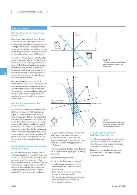
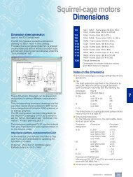
5 Overcurrent <strong>Protection</strong> / <strong>7SJ63</strong>5<strong>Protection</strong> functionsDirectional time-overcurrent protection(ANSI 67, 67N)Directional phase and earth protection areseparate functions. They operate in parallelto the non-directional overcurrent elements.Their pickup values and delay times can beset separately. Definite-time and inverse-timecharacteristic is offered. The tripping characteristiccan be rotated about ± 180 degrees.By means of voltage memory, directionalitycan be determined reliably even for close-in(local) faults. If the switching device closesonto a fault and the voltage is too low to determinedirection, directio- nality (directionaldecision) is made with voltage fromthe voltage memory. If no voltage exists inthe memory, tripping occurs according tothe coordination schedule.For earth protection, users can choosewhether the direction is to be determined viazero-sequence system or negative-sequencesystem quantities (selectable). Using negative-sequencevariables can be advantageousin cases where the zero voltage tends to bevery low due to unfavorable zero-sequenceimpedances.Fig. 5/113Directional characteristic of thedirectional time-overcurrentprotectionDirectional comparison protection(cross-coupling)It is used for selective protection of sectionsfed from two sources with instantaneoustripping, i.e. without the disadvantage oftime coordination. The directional comparisonprotection is suitable if the distances betweenthe protection stations are not significantand pilot wires are available for signaltransmission. In addition to the directionalcomparison protection, the directional coordinatedtime-overcurrent protection is usedfor complete selective backup protection. Ifoperated in a closed-circuit connection, aninterruption of the transmission line is detected.(Sensitive) directional earth-fault detection(ANSI 64, 67Ns, 67N)For isolated-neutral and compensated networks,the direction of power flow in the zerosequence is calculated from the zero-sequencecurrent I 0 and zero-sequence voltage V 0.For networks with an isolated neutral, the reactivecurrent component is evaluated; forcompensated networks, the active currentcomponent or residual resistive current isevaluated. For special network conditions,5/122e.g. high-resistance earthed networks withohmic-capacitive earth-fault current orlow-resistance earthed networks withohmic-inductive current, the tripping characteristicscan be rotated approximately± 45 degrees.Two modes of earth-fault direction detectioncan be implemented: tripping or “signallingonly mode”.It has the following functions:• TRIP via the displacement voltage V E.• Two instantaneous elements or oneinstantaneous plus one user-definedcharacteristic.• Each element can be set in forward,reverse, or non-directional.• The function can also be operated in theinsensitive mode as an additionalshort-circuit protection.Fig. 5/114Directional determination usingcosine measurements forcompensated networks(Sensitive) earth-fault detection(ANSI 50Ns, 51Ns / 50N, 51N)For high-resistance earthed networks, a sensitiveinput transformer is connected to aphase-balance neutral current transformer(also called core-balance CT).The function can also be operated in theinsensitive mode as an additional shortcircuitprotection.<strong>Siemens</strong> SIP · 2006
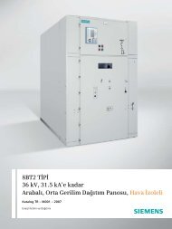
5 Overcurrent <strong>Protection</strong> / <strong>7SJ63</strong><strong>Protection</strong> functionsIntermittent earth-fault protectionIntermittent (re-striking) faults occur due toinsulationweaknessesincablesorasaresultof water penetrating cable joints. Such faultseither simply cease at some stage or developinto lasting short-circuits. During intermittentactivity, however, star-point resistors innetworks that are impedance-earthed mayundergo thermal overloading. The normalearth-fault protection cannot reliably detectand interrupt the current pulses, some ofwhich can be very brief.The selectivity required with intermittentearth faults is achieved by summating theduration of the individual pulses and bytriggering when a (settable) summed time isreached. The response threshold I IE>evaluatesthe r.m.s. value, referred to one systemsperiod.Phase-balance current protection (ANSI 46)(Negative-sequence protection)In line protection, the two-element phasebalancecurrent/negative-sequence protectionpermits detection on the high side ofhigh-resistance phase-to-phase faults andphase-to-earth faults that are on the low sideof a transformer (e.g. with the switch groupDy 5). This provides backup protection forhigh-resistance faults beyond the transformer.Breaker failure protection (ANSI 50BF)If a faulted portion of the electrical circuit isnot disconnected upon issuance of a tripcommand, another command can be initiatedusing the breaker failure protectionwhich operates the circuit-breaker, e.g. of anupstream (higher-level) protection relay.Breaker failure is detected if, after a trip command,current is still flowing in the faultedcircuit. As an option, it is possible to makeuse of the circuit-breaker position indication.High-impedance restricted earth-fault protection(ANSI 87N)The high-impedance measurement principleis an uncomplicated and sensitive methodfor detecting earth faults, especially on transformers.It can also be applied to motors,generators and reactors when these are operatedon an earthed network.When the high-impedance measurementprinciple is applied, all current transformersin the protected area are connected in parallelandoperatedononecommonresistorofrelativelyhigh R whose voltage is measured (seeFig. 5/115). In the case of 7SJ6 units, the voltageis measured by detecting the currentthrough the (external) resistor R at the sensitivecurrent measurement input I EE.Thevaristor V serves to limit the voltage in theevent of an internal fault. It cuts off the highmomentary voltage spikes occurring at transformersaturation. At the same time, this resultsin smoothing of the voltage without anynoteworthy reduction of the average value.If no faults have occurred and in the event ofexternal faults, the system is at equilibrium,and the voltage through the resistor is approximatelyzero. In the event of internalfaults, an imbalance occurs which leads to avoltage and a current flow through the resistorR.The current transformers must be of thesame type and must at least offer a separatecore for the high-impedance restrictedearth-fault protection. They must in particularhave the same transformation ratio andan approximately identical knee-point voltage.They should also demonstrate only minimalmeasuring errors.Auto-reclosure (ANSI 79)Multiple reclosures can be defined by theuser and lockout will occur if a fault is presentafter the last reclosure. The followingfunctions are possible:• 3-pole ARC for all types of faults• Separate settings for phase and earth faults• Multiple ARC, one rapid auto-reclosure(RAR) and up to nine delayedauto-reclosures (DAR)• Starting of the ARC depends on the tripcommand selection (e.g. 46, 50, 51, 67)• Blocking option of the ARC via binaryinputs• ARC can be initiated externally or via CFC• The directional and non-directional elementscan either be blocked or operatednon-delayed depending on the autoreclosurecycle• Dynamic setting change of the directionaland non-directional elements can be activateddepending on the ready ARFig. 5/115High-impedance restricted earthfaultprotectionThermal overload protection (ANSI 49)For protecting cables and transformers,an overload protection with an integratedpre-warning element for temperature andcurrent can be applied. The temperature iscalculated using a thermal homogeneousbodymodel (according to IEC 60255-8),which takes account both of the energy enteringthe equipment and the energy losses.The calculated temperature is constantly adjustedaccordingly. Thus, account is taken ofthe previous load and the load fluctuations.For thermal protection of motors (especiallythe stator) a further time constant can be setso that the thermal ratios can be detectedcorrectly while the motor is rotating andwhen it is stopped. The ambient temperatureor the temperature of the coolant can be detectedserially via an external temperaturemonitoring box (resistance-temperature detectorbox, also called RTD- box). The thermalreplica of the overload function is automaticallyadapted to the ambient conditions.If there is no RTD-box it is assumed that theambient temperatures are constant.Settable dropout delay timesIf the devices are used in parallel with electromechanicalrelays in networks with intermittentfaults, the long dropout times of theelectromechanical devices (several hundredmilliseconds) can lead to problems in termsof time grading. Clean time grading is onlypossible if the dropout time is approximatelythe same. This is why the parameter of dropouttimes can be defined for certain functionssuch as time-overcurrent protection, earthshort-circuit and phase-balance current protection.5<strong>Siemens</strong> SIP · 20065/123