SIPROTEC 4 7SJ63 Multifunction Protection Relay - Siemens
SIPROTEC 4 7SJ63 Multifunction Protection Relay - Siemens
SIPROTEC 4 7SJ63 Multifunction Protection Relay - Siemens

You also want an ePaper? Increase the reach of your titles
YUMPU automatically turns print PDFs into web optimized ePapers that Google loves.
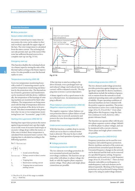
5 Overcurrent <strong>Protection</strong> / <strong>7SJ63</strong>5<strong>Protection</strong> functionsn Motor protectionRestart inhibit (ANSI 66/86)If a motor is started up too many times insuccession, the rotor can be subject to thermaloverload, especially the upper edges ofthebars.Therotortemperatureiscalculatedfrom the stator current. The reclosing lockoutonly permits start-up of the motor if therotor has sufficient thermal reserves for acomplete start-up (see Fig. 5/116).Emergency start-upThis function disables the reclosing lockoutvia a binary input by storing the state of thethermal replica as long as the binary input isactive.Itisalsopossibletoresetthethermalreplica to zero.Fig. 5/116Temperature monitoring (ANSI 38)Up to two temperature monitoring boxeswith a total of 12 measuring sensors can beused for temperature monitoring and detectionby the protection relay. The thermal statusof motors, generators and transformerscan be monitored with this device. Additionally,the temperature of the bearings of rotatingmachines are monitored for limit valueviolation. The temperatures are being measuredwith the help of temperature detectorsat various locations of the device to be protected.This data is transmitted to the protectionrelay via one or two temperature monitoringboxes (see “Accessories”, page 5/149).Starting time supervision (ANSI 48/14)Starting time supervision protects the motoragainst long unwanted start-ups that mightoccur in the event of excessive load torque orexcessive voltage drops within the motor, orif the rotor is locked. Rotor temperature iscalculated from measured stator current. Thetripping time is calculated according to thefollowing equation:for I > I MOTOR STARTt = ⎛ I A ⎞⎜ ⎟ ⋅ T⎝ I ⎠I5/1242I MOTOR STARTtI AT AA= Actual current flowing= Pickup current to detect a motorstart= Tripping time= Rated motor starting current= Tripping time at rated motorstarting current1) The 45 to 55, 55 to 65 Hz range is availablefor f N= 50/60 Hz.If the trip time is rated according to theabove formula, even a prolonged start-upand reduced voltage (and reduced start-upcurrent) will be evaluated correctly. The trippingtime is inverse (current dependent).A binary signal is set by a speed sensor to detecta blocked rotor. An instantaneous trippingis effected.Phase-balance current protection (ANSI 46)(Negative-sequence protection)The negative-sequence / phase-balance currentprotection detects a phase failure or loadunbalance due to network asymmetry andprotects the rotor from impermissible temperaturerise.Undercurrent monitoring (ANSI 37)With this function, a sudden drop in current,which can occur due to a reduced motorload, is detected. This may be due to shaftbreakage, no-load operation of pumps or fanfailure.n Voltage protectionOvervoltage protection (ANSI 59)The two-element overvoltage protection detectsunwanted network and machineovervoltage conditions. The function can operateeither with phase-to-phase voltage (default)or with the negative phase-sequencesystem voltage. Three-phase and single-phaseconnections are possible.Undervoltage protection (ANSI 27)The two-element undervoltage protectionprovides protection against dangerous voltagedrops (especially for electric machines).Applications include the isolation of generatorsor motors from the network to avoidundesired operating states and a possible lossof stability. Proper operating conditions ofelectrical machines are best evaluated withthe positive-sequence quantities. The protectionfunction is active over a wide frequencyrange (45 to 55, 55 to 65 Hz) 1) .Evenwhenfalling below this frequency range the functioncontinues to work, however, with agreater tolerance band.The function can operate either with the positivephase-sequence system voltage (default)or with the phase-to-phase voltages, and canbe monitored with a current criterion.Three-phase and single-phase connectionsare possible.Frequency protection (ANSI 81O/U)Frequency protection can be used for overfrequencyand underfrequency protection.Electric machines and parts of the system areprotected from unwanted speed deviations.Unwanted frequency changes in the networkcan be detected and the load can be removedat a specified frequency setting. Frequencyprotection can be used over a wide frequencyrange (45 to 55, 55 to 65 Hz) 1) .Therearefourelements (selectable as overfrequency orunderfrequency) and each element can bedelayed separately. Blocking of the frequencyprotection can be performed if using a binaryinput or by using an undervoltage element.<strong>Siemens</strong> SIP · 2006