
Create successful ePaper yourself
Turn your PDF publications into a flip-book with our unique Google optimized e-Paper software.
ENGLISH<br />
1<br />
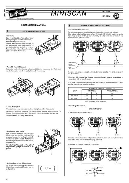
• Unpacking<br />
Open the cardboard box. Remove the projector<br />
from is packing and place it on a flat surface.<br />
Remove socket placed in packing.<br />
Take the labels about lamp replacing out of the<br />
box and select the one in the language of the<br />
country in which the spotlight is installed.<br />
Remove the label written in Italian from position<br />
(2) and replace with the new label.<br />
6<br />
3<br />
®<br />
INSTRUCTION MANUAL<br />
SPOTLIGHT INSTALLATION<br />
• Assembly of spotlight bracket<br />
Position the bracket (3) at the required height and tighten the thumbscrews (4). The bracket<br />
can also be mounted beneath the spotlight in exactly the same way.<br />
4<br />
• Fixing the projector<br />
The projector can be put in any position without altering its operating characteristics.<br />
IMPORTANT: mount the spotlight in the required position using the holes provided in the<br />
bracket. We re<strong>com</strong>mend using two 10 diam. screws with relevant nuts and static washers.<br />
For overhead use, fit a safety chain or cord.<br />
• Attaching the safety bracket<br />
If the spotlight is to be fitted in a public place<br />
(discotheque, bar, television studio, etc.) it is<br />
obligatory to mount the auxiliary bracket (5).<br />
This must be securely fixed to the framework<br />
for the spotlight and then hooked on to the spotlight’s<br />
knobs (6).<br />
The attaching of the safety cord is optional<br />
only when the spotlight is mounted on the<br />
ground.<br />
• Minimum distance from lighted objects<br />
The spotlight must be positioned so that objects<br />
lit by the beam are at least 0.5 metres from the<br />
spotlight’s lens.<br />
5<br />
2<br />
0,5 m<br />
<strong>MINISCAN</strong><br />
6<br />
1<br />
<strong>MINISCAN</strong><br />
2<br />
• Connection to the mains supply<br />
We advise connecting every projector with individual switches so that they can be switched on<br />
and off separately.<br />
– Important: it is essential that the earth connection for each projector is carried out in<br />
accordance with current standards.<br />
Once all the above-mentioned operations have been carried out, press mains switch (I) making<br />
sure that automatic reset procedure has begun.<br />
LAMP<br />
POWER SUPPLY AND ADJUSTMENT<br />
The projector must receive the voltage/frequency indicated on the back of the projector.<br />
If the voltage, in the installation place, is from 110 Volts to 125 Volts, it is possible to use the<br />
Power Supplier Code C21080, available from Clay Paky. For connection of this item, see<br />
instructions at the end of this section.<br />
Alimentazione<br />
Mains<br />
Alimentation<br />
Netz<br />
Alimentacion<br />
0 - 10V<br />
7<br />
L<br />
N<br />
VA<br />
POWER CONSUMPTION V.A. with 220 Vac.<br />
WITH PFC (*)<br />
HTI 300 W 400 43<br />
800<br />
µF<br />
WITHOUT PFC (*)<br />
HTI 150 W 200 35<br />
500<br />
• Control signal connection<br />
– Independent operation of the projectors<br />
(*) PFC = Power Factor Correction<br />
0 - 10V 0 - 10V 0 - 10V<br />
5 PAN<br />
0-10 V CONNECTION<br />
Connection between the controller and projector must be by multicore cable having 8 wires with a<br />
cross-section of 0.25 mm 2 and DIN 8PIN 45° plugs and sockets.<br />
– Simultaneous and equal operation of the projectors<br />
7<br />
8<br />
6<br />
TILT<br />
COL<br />
5<br />
3 1<br />
2<br />
4<br />
Is<br />
PAN GOBO<br />
HTI 300 W<br />
HTI 150 W<br />
VA<br />
i
DMX 512<br />
RS 232/423<br />
• Projector adddressing (for digital signals)<br />
Each <strong>MINISCAN</strong> occupies 4 channels. To ensure that the control signals are properly directed<br />
to each projector the projector needs to have a address given to it. This is to be done for each<br />
and every <strong>MINISCAN</strong> projector by changing the DIL switches as set out in the table below.<br />
THE DIGITAL START<br />
ADDRESS IS THE SUM<br />
OF THE NUMBERS<br />
PRODUCED BY THE<br />
SELECTED SWITCHES<br />
DIGITAL INPUT<br />
DIGITAL<br />
START<br />
ADDRESS<br />
AND<br />
OPTIONS<br />
SELECT<br />
EG.<br />
RESPOND<br />
C.1 - 4<br />
EG.<br />
RESPOND<br />
C.17 - 20<br />
RUN TEST<br />
SEQUENCE<br />
1<br />
2<br />
4<br />
8<br />
16<br />
32<br />
64<br />
128<br />
256<br />
TEST<br />
ON<br />
DMX 512 : 1 = ,2 = SIG - ,3 = SIG +<br />
RS232/423 : 1 = ,2 = SIG ,3 = SIG<br />
Projector 1 - Channels 1-4<br />
Projector 2 - Channels 5-8<br />
Projector 3 - Channels 9-12<br />
Projector 4 - Channels 13-16<br />
Projector 5 - Channels 17-20<br />
Projector 6 - Channels 21-24<br />
Projector 7 - Channels 25-28<br />
Projector 8 - Channels 29-32<br />
Projector 9 - Channels 33-36<br />
Projector 10 - Channels 37-40<br />
Projector 11 - Channels 41-44<br />
Projector 12 - Channels 45-48<br />
Projector 13 - Channels 49-52<br />
Projector 14 - Channels 53-56<br />
Projector 15 - Channels 57-60<br />
RS 232/423 - DMX 512 CONNECTION<br />
Connection between the controller and the projector or between one projector and another must<br />
be by screened 2 core cable. Canon 5PIN XLR plugs and sockets.<br />
When using DMX, a terminating plug containing a 100 R resistor between pins 2 and 3 must be<br />
inserted in the last spotlight. This is not required for PMX.<br />
The wires must not <strong>com</strong>e into contact with each other or with the metal covering of the<br />
plug.<br />
The screen of the cable should be connected to pin 1 and the body of the XLR plug or<br />
socket.<br />
RS232/423<br />
(PMX)<br />
SCREEN<br />
1 2<br />
3<br />
5 4<br />
CODIFICA<br />
SIGNAL<br />
SIGNAL<br />
1 2 3 4 5 6 7 8 9 10 11 12<br />
ON<br />
OFF<br />
ON<br />
OFF<br />
With the projector on, put the test switch in position ON for a few seconds to automatically reset<br />
the projector. Leave the test switch ON to <strong>com</strong>plete the self-test; at the end of the self-test<br />
return the test switch to OFF.<br />
ON<br />
OFF<br />
ON<br />
OFF<br />
ON<br />
OFF<br />
ON<br />
OFF<br />
ON<br />
OFF<br />
ON<br />
OFF<br />
ON<br />
OFF<br />
ON<br />
OFF<br />
ON<br />
OFF<br />
ON<br />
OFF<br />
ON<br />
OFF<br />
ON<br />
OFF<br />
ON<br />
OFF<br />
ON<br />
OFF<br />
1<br />
PAN<br />
TILT<br />
2<br />
4<br />
DMX<br />
512<br />
Projector selection<br />
COL Is<br />
PAN<br />
ANALOGUE<br />
INPUTS 0 - 10V<br />
8<br />
16<br />
32<br />
SCREEN<br />
64<br />
1 2<br />
3<br />
5 4<br />
TILT<br />
GOBO<br />
128<br />
256<br />
TEST<br />
SIGNAL<br />
SIGNAL<br />
3<br />
CHANNEL<br />
CHANNEL<br />
POSITION<br />
1 COLOUR Keep at 0% (White)<br />
2 GOBOS 100% (Open)<br />
3 PAN 50% (Mild-way position)<br />
4 TILT 50% (Mild-way position)<br />
POSITION<br />
1 COLOUR Keep at 0% (White)<br />
2 GOBOS Adjust the Gobo as required<br />
3 PAN 50% (Mild-way position)<br />
4 TILT 50% (Mild-way position)<br />
FOCUSSING<br />
• Aiming the projector<br />
Before adjusting the spotlight, prepare the channels as shown in the following table.<br />
Once the above-mentioned operations have been carried out, proceed to loosen knob (4) and<br />
move the projector along bracket (3) until light beam is focussed on centre spot.<br />
Tighten knobs (4).<br />
• Adjusting the lens<br />
Set out the channels as shown in the table below and carry out the operations described.<br />
Loosen the thumbscrew and rotate the lens (9) on its axis until the projected image is in focus.<br />
Lock in position with the knob (8).<br />
4<br />
CHANNEL FUNCTIONS AND OPTIONS<br />
Channel<br />
1<br />
2<br />
3<br />
4<br />
Function<br />
COLOUR<br />
GOBOS / DIMMER / STOPPER-STROBE<br />
PAN<br />
TILT<br />
To chose an option, set the DIL switches as explained below.<br />
1<br />
2<br />
4<br />
8<br />
16<br />
32<br />
64<br />
128<br />
256<br />
TEST<br />
ON<br />
OPTION SELECT<br />
1 2 3 4 5 6 7 8 9 10 11 12<br />
4<br />
3<br />
PAN<br />
TILT<br />
8 9<br />
7<br />
ENGLISH
• COLOUR - channel 1<br />
• PAN - channel 3<br />
8<br />
10<br />
9<br />
8<br />
7<br />
6<br />
5<br />
4<br />
3<br />
2<br />
1<br />
0<br />
9<br />
8<br />
7<br />
6<br />
5<br />
4<br />
3<br />
2<br />
1<br />
0<br />
10<br />
9<br />
8<br />
7<br />
6<br />
5<br />
4<br />
3<br />
2<br />
1<br />
0<br />
• GOBOS / DIMMER / STOPPER-STROBE - channel 2<br />
10<br />
9<br />
8<br />
7<br />
6<br />
5<br />
4<br />
3<br />
2<br />
1<br />
0<br />
ROSA<br />
BLU<br />
ARANCIO<br />
VERDE<br />
VIOLA<br />
GIALLO<br />
ROSSO<br />
BIANCO<br />
Linear colour change following the<br />
movement of the slider.<br />
In this way you can stop the colour<br />
wheel in a mid-way position between<br />
two colours thus giving bi-colour<br />
beams.<br />
From 50% to 100% the wheel begins<br />
to rotate with increasing speed: 0 to<br />
300 r.p.m.<br />
Shutter opens gradually in cursor<br />
range from 0 to 50% until full aperture.<br />
From 30% to 50% strobe effect is<br />
obtained with increase in speed from<br />
1 to 7 flash/second.<br />
On 50% aperture is fixed.<br />
From 60% GOBOS sequence begins<br />
until 85% as indicated in diagram.<br />
From 85 to 100% of cursor range,<br />
aperture ix fixed.<br />
1<br />
2<br />
4<br />
8<br />
16<br />
32<br />
64<br />
128<br />
256<br />
TEST<br />
PAN<br />
TILT<br />
ON<br />
1 2 3 4 5 6 7 8 9 10 11 12<br />
Standard operation<br />
Horizontal movement of the mirror (PAN)<br />
as you advance the slider.<br />
Gradual advance from one end of the slider<br />
to the other.<br />
The mirror can be held in any position at will.<br />
1<br />
2<br />
4<br />
8<br />
16<br />
32<br />
64<br />
128<br />
256<br />
10 TEST<br />
ON<br />
PAN<br />
TILT<br />
1 2 3 4 5 6 7 8 9 10 11 12<br />
Optional operation<br />
The start position and the direction of<br />
movement are inverted.<br />
• TILT - channel 4<br />
5<br />
BEAM OPENING m<br />
10<br />
9<br />
8<br />
7<br />
6<br />
5<br />
4<br />
3<br />
2<br />
1<br />
0<br />
10<br />
9<br />
8<br />
7<br />
6<br />
5<br />
4<br />
3<br />
2<br />
1<br />
0<br />
Lamp HMI HTI 1200 150<br />
4<br />
3<br />
2<br />
1<br />
0<br />
1<br />
2<br />
3<br />
1<br />
2<br />
4<br />
8<br />
16<br />
32<br />
64<br />
128<br />
256<br />
TEST<br />
ON<br />
PAN<br />
TILT<br />
1 2 3 4 5 6 7 8 9 10 11 12<br />
Standard operation<br />
Vertical motion of the mirror (TILT) happens<br />
simultaneously with the advance of<br />
the adjustment dial. Gradual advance from<br />
one end of the dial to the other.<br />
The mirror can be held in any position at will.<br />
1<br />
2<br />
4<br />
8<br />
16<br />
32<br />
64<br />
128<br />
256<br />
TEST<br />
PAN<br />
TILT<br />
ON<br />
1 2 3 4 5 6 7 8 9 10 11 12<br />
Optional operation<br />
The start position and the direction of<br />
movement are inverted.<br />
OBJECTIVE LENS<br />
Objective lens 1:2,5/165 - Standard dotation<br />
Lamp. HTI 300 10450 2610 1160 650 450 290 230 165<br />
BEAM OPENING m<br />
5700 1400 600 370 232 161 118 90<br />
LUX<br />
4<br />
0 2,5 5 7,5 10 12,5 15<br />
17,5 20 DISTANCE m<br />
0 0,4 0,79 1,2 1,60 2,00 2,40 2,40 2,80 3,20 DIAMETER m<br />
Objective lens 1:2,2/100 - Available on request<br />
Lamp. HTI 300 4000 1000 445 250 160 111 81 62<br />
Lamp HMI HTI 1200 150<br />
4<br />
2000 500 220 125 80 55 41 32<br />
3<br />
2<br />
1<br />
0<br />
1<br />
2<br />
3<br />
4<br />
0 2,5 5 7,5 10 12,5 15 17,5 20 DISTANCE m<br />
0 0,67 1,34 2,00 2,70 3,37 4,05 4,72 5,40 DIAMETER m<br />
15° 20'<br />
9°<br />
LUX
K Lux<br />
5<br />
10<br />
8<br />
6<br />
4<br />
3<br />
6<br />
2<br />
10<br />
8<br />
6<br />
4<br />
3<br />
2<br />
10<br />
8<br />
6<br />
4<br />
3<br />
2<br />
10<br />
8<br />
6<br />
4<br />
3<br />
2<br />
1<br />
4<br />
3<br />
2<br />
HTI 300W 1:2,2<br />
HTI 150W 1:2,2<br />
MAINTENANCE<br />
Important: disconnect from the mains supply<br />
before carrying out any work on the<br />
projector.<br />
• Opening the projector<br />
Slide cover (10) from the projector.<br />
Carry out the maintenance and then replace<br />
covers.<br />
• HTI 150 W Lamp replacement<br />
Slide the cover off the spotlight and then<br />
remove the lamp (11) by pulling it up from the<br />
socket (12).<br />
Insert the new lamp in the socket, ensuring that<br />
the pins are correctly positioned.<br />
• HTI 300 W Lamp replacement<br />
After having opened the spotlight, loosen the<br />
two ring nuts (13) at the ends of the lamp to be<br />
replaced and take it out from the brackets.<br />
Take the new lamp from the packaging and<br />
carefully read the enclosed instruction leaflet.<br />
Release the two ring nuts (13) at the ends,<br />
insert the lamp into the brackets (14) and then<br />
re-tighten the ring nuts.<br />
Important: to achieve an even beam of light,<br />
the knob (15) at the centre of the bulb must be<br />
facing down.<br />
HTI 300W 1:2,5<br />
0 5 10 15 20 25 m<br />
DISTANCE m<br />
HTI 150W 1:2,5<br />
15<br />
10<br />
12<br />
14<br />
13<br />
13<br />
11<br />
• Lens replacement<br />
Slide the cover off the spotlight, locate the<br />
optic unit and undo the 2 screws (16) which<br />
hold the lens holder plates (17). Pull the lenses<br />
(18) and (19) up and out.<br />
Insert the new lenses into the housings, reposition<br />
the two lens holder plates (17) and retighten<br />
the 2 screws (16).<br />
• Mirror replacement<br />
To replace the mirror (20), lever out the spring<br />
(21) with a screwdriver and draw out the mirror<br />
by pulling up.<br />
Insert the new mirror into the housing and attach<br />
to the spring (21) with silicon.<br />
• Replacing dichroic filter<br />
With the spotlight open, locate the filter to be<br />
replaced, grip between your fingers and push<br />
towards the mobile anchoring point (28) until<br />
the filter <strong>com</strong>es out from the fixed anchoring<br />
points. Bend the filter outwards and take out.<br />
Insert the new filter into the mobile point (28)<br />
and anchor into the two fixed points (29).<br />
• Red : code 080303/005<br />
• Yellow: code 080303/002<br />
• Violet: code 080303/004<br />
• Green: code 080303/003<br />
• Orange: code 080303/007<br />
• Blue: code 080303/001<br />
• Pink: code 080303/006<br />
• Replacing Gobo disc<br />
With the spotlight open, locate the Gobo disc<br />
(22) and its locking pin (23). Unscrew the pin<br />
and draw out the disc on its axis until it <strong>com</strong>es<br />
off the motor shaft. (24).<br />
Slide on the new Gobo disc until reaching the<br />
end, ensuring that the locking pin is exactly in<br />
the reference slot on the motor shaft. Tighten<br />
the pin (23) and check that the disc is centred.<br />
• Replacement of fuse<br />
To replace the fuse, press the tab (25) and<br />
take out the fuse holder (26).<br />
Having changed the fuse with a new one of<br />
the type indicated on the fuseholder’s identification<br />
plate (27), insert this unit until the tab<br />
(25) clicks shut.<br />
• Periodical cleaning<br />
To ensure that the light output of the projector<br />
does not fall it is essential to carry out periodical<br />
cleaning of those parts subject to the build<br />
up of dust and grease.<br />
Perfect working can be assured by following the<br />
instructions given below (unless installed in<br />
exceptionally dirty environments).<br />
Use a soft cloth and any glass detergent liquid<br />
to remove dirt from lenses and filters.<br />
Attention: Never use solvents or alcohol.<br />
Parts requiring frequent cleaning<br />
Parts requiring monthly cleaning<br />
Use a brush to clean the Gobos.<br />
We advise cleaning the internal parts thoroughly<br />
once a year.<br />
Remove the dust using a brush and an ordinary<br />
vacuum cleaner.<br />
19 17 16 18<br />
23 22<br />
27<br />
5 x 20<br />
5A T<br />
250 V<br />
24<br />
HTI 300 W<br />
HTI 150 W<br />
29<br />
20 21<br />
FUSE FUSE<br />
26 25<br />
28<br />
5 x 20<br />
1A T<br />
250 V<br />
9<br />
ENGLISH
7<br />
8<br />
110-125 VOLTS EXTERNAL FEEDER<br />
The feeder must be connected on the outside<br />
of the <strong>MINISCAN</strong> projector as shown below.<br />
– Fix the feeder box where you intend to fix the<br />
<strong>MINISCAN</strong>, using the two lateral holes on<br />
the bottom of the box.<br />
– Remove the nut on the central base plate<br />
screw.<br />
– Fix the <strong>MINISCAN</strong> to the feeder by inserting<br />
this screw in the correct hole on the projector<br />
bracket. Tighten the self-locking nut.<br />
– Connect the power cable to the socket on<br />
the rear panel of the <strong>MINISCAN</strong>.<br />
– Use the mobile socket supplied with the<br />
<strong>MINISCAN</strong> to connect the feeder to the<br />
mains supply.<br />
Power supplying box technical specifications:<br />
Incorporated autotransformer.<br />
Incorporated power correction factor.<br />
Voltage: Standard 110 V.<br />
At request 100 or 125 V<br />
10<br />
PROJECTOR FAILS TO LIGHT UP<br />
•<br />
•<br />
•••<br />
• •<br />
•<br />
9<br />
FAULTY ELECTRONICS<br />
FAULTY PROJECTION<br />
TROUBLE SHOOTING<br />
REDUCTION IN BRIGHTNESS<br />
PROJECTION WITH HALO EFFECT<br />
210<br />
170<br />
PFC: Reduce Power Consumption<br />
from 560 V.A. a 250 V.A.<br />
Dimensioni: 210 x 170 x 85 mm<br />
Peso: 3,6 kg<br />
FAULT<br />
POSSIBLE CAUSES CHECKS AND REMEDY<br />
No mains power Check for mains power at the supply<br />
socket and check the fuse.<br />
• Lamp worn out or defective<br />
Signal transmission cable short-circuited<br />
or disconnected<br />
Replace lamp (see instructions)<br />
Change cable.<br />
CARATTERISTICHE ELETTRO-MECCANICHE<br />
Power supply<br />
– HTI 150 W version:<br />
• 200-240 V 50/60 Hz<br />
– HTI 300 W version:<br />
• 220-240 V 50/60 Hz<br />
Lamp<br />
Two alternative versions are available<br />
1. Metal halide discharge lamp, with built-in<br />
transformer.<br />
– HTI 150 W.<br />
– Socket: GY9.5.<br />
– Lamp life: 750 hours on average.<br />
– Flux: 10,000 lumen.<br />
– Colour temperature: 6,500 K<br />
2. Metal halide discharge lamp, with built-in<br />
transformer.<br />
– HTI 300 W.<br />
– Socket: SFC 10-4.<br />
– Lamp life: 750 hours on average.<br />
– Flux: 20,000 lumen.<br />
– Colour temperature: 6,500 K<br />
Power consumption<br />
– See table<br />
Wrong coding See instructions for addressing spotlight.<br />
Electronic circuit fault Call in authorized technician.<br />
Broken lens Call in authorized technician.<br />
Dust and grese deposits Carry out cleaning operation<br />
(see instructions)<br />
Dirty objective lens and mirror Carry out cleaning operation<br />
(see instructions)<br />
Motors<br />
– 4 stepper motors, controlled by microprocessor.<br />
OPTICAL SYSTEM<br />
Optical group<br />
– Made from die-cast aluminium, consisting of<br />
TECHNICAL CHARACTERISTICS<br />
85<br />
double condenser lens and high efficiency<br />
parabolic mirror.<br />
Objective lens<br />
– Interchangeable with two different possibilities<br />
Standard 1:2.5/165 mm<br />
Wide-angle lens on request 1:2.2/100mm<br />
MIRROR ADAPTOR<br />
– Fixed on spotlight body<br />
Mirror<br />
– Very high luminous yield<br />
Rotation<br />
– Using two microstepping microprocessor controlled<br />
motors.<br />
– Variable rotation speed; Maximum values:<br />
• horizontal movement (pan)<br />
0.4 sec/150°<br />
• vertical movement (tilt)<br />
0.3 sec/110°<br />
– Smooth and continuous movement thanks to<br />
high resolution microstepping (5376 steps for<br />
pan, 1972 for tilt)<br />
CONTROL SYSTEM<br />
Channels<br />
– 4 control channels<br />
– Channel functions<br />
Channel 1 - Colour Disk<br />
Channel 2 - Gobos / Dimmer / Stopper-Strobe<br />
Channel 3 - Horizontal Mirror movement<br />
Channel 4 - Vertical Mirror movement<br />
Input<br />
– <strong>MINISCAN</strong> can accept either analogue or digital<br />
control signals from controllers or <strong>com</strong>puters.<br />
• analogue input: from 0 to 10 V<br />
• digital serial input: RS 232/423 or DMX 512<br />
SAFETY FEATURES<br />
Safety Devices<br />
– Equipment manufactured according to safety<br />
regulations in force: degree of protection IP 20.<br />
Devices<br />
– Automatic power supply cut out in case of<br />
overheating or cooling system failure.<br />
Cooling system<br />
– Forced ventilation cooling with axial fan.<br />
10<br />
M<br />
M<br />
M<br />
M<br />
L<br />
N<br />
E<br />
BROWN<br />
GREY<br />
ORANGE<br />
GREEN<br />
BROWN<br />
GREY<br />
ORANGE<br />
GREEN<br />
L<br />
N<br />
E<br />
BROWN<br />
GREY<br />
ORANGE<br />
GREEN<br />
BROWN<br />
GREY<br />
ORANGE<br />
GREEN<br />
fuse<br />
fuse<br />
B1<br />
B2<br />
B3<br />
B4<br />
A1<br />
A2<br />
A3 TILT<br />
A4<br />
fuse<br />
fuse<br />
B1<br />
B2<br />
B3<br />
B4<br />
MOT.<br />
PAN<br />
MOT.<br />
MOT.<br />
PAN<br />
A1<br />
A2<br />
A3 TILT<br />
A4<br />
MOT.<br />
SW<br />
20V<br />
20V<br />
SW<br />
20V<br />
20V<br />
WIRING DIAGRAM<br />
FAN<br />
FAN<br />
HTI 300 W<br />
MSW 0<br />
BACK PANNEL<br />
DIGITAL ANALOGUE<br />
HTI 150 W<br />
0<br />
BACK PANNEL<br />
BALLAST<br />
230V-50Hz<br />
DIGITAL ANALOGUE<br />
GENERAL CHARACTERISTIC<br />
Housing<br />
– Die-cast aluminium.<br />
– Epoxy paint finish.<br />
Bracket<br />
– Steel, epoxy paint finish mounting bracket.<br />
– Two positions.<br />
– Secondary safety support.<br />
Working Position<br />
– Any position.<br />
Inside<br />
– Easily accessible thanks to large opening<br />
cover.<br />
Dimensions<br />
HTI 150 W: mm 238x150x582; peso 9,2 kg<br />
HTI 300 W: mm 238x150x582; peso 11,2 kg<br />
Clay Paky reserves the right to modify any of the characteristics mentioned in its catalogue without prior<br />
notice to improve production quality.<br />
BALLAST<br />
230V-50Hz<br />
230V-60Hz<br />
200V-50Hz<br />
200V-60Hz<br />
L<br />
N<br />
230V-60Hz<br />
200V-50Hz<br />
200V-60Hz<br />
L<br />
N<br />
STOP<br />
STROBO<br />
COLOR<br />
DISK<br />
E<br />
L<br />
N<br />
STOP<br />
STROBO<br />
COLOR<br />
DISK<br />
E<br />
L<br />
N<br />
t<br />
t<br />
D<br />
L<br />
IGNITOR<br />
N<br />
GREEN<br />
C4<br />
ORANGE<br />
C3<br />
GREY<br />
C2<br />
BROWN<br />
C1<br />
GREEN<br />
D4<br />
ORANGE<br />
D3<br />
GREY<br />
D2<br />
BROWN<br />
D1<br />
D<br />
L<br />
IGNITOR<br />
N<br />
GREEN<br />
C4<br />
ORANGE<br />
C3<br />
GREY<br />
C2<br />
BROWN<br />
C1<br />
GREEN<br />
D4<br />
ORANGE<br />
D3<br />
GREY<br />
D2<br />
BROWN<br />
D1<br />
M<br />
M<br />
M<br />
M