Aerospace Research - ISTC Funded Projects 1994-2009
Aerospace Research - ISTC Funded Projects 1994-2009
Aerospace Research - ISTC Funded Projects 1994-2009

Create successful ePaper yourself
Turn your PDF publications into a flip-book with our unique Google optimized e-Paper software.
128<br />
<strong>Aerospace</strong> <strong>Research</strong>. Volume 1<br />
Background<br />
Development of a hightemperature combustion<br />
chamber is one of the most important<br />
problems as the increase of gas temperature<br />
in airbreathing engine improves engine<br />
performances. A hightemperature annular<br />
combustion chamber with minimum emission<br />
can be designed based on principles which<br />
are quite different from conventional. If the<br />
airfuel ratio in the combustion chamber<br />
with standard operation process decreases<br />
to the level of α < 1.8...1.5, the combustion<br />
efficiency decreases abruptly whereas the<br />
value of harmful emissions in the exhaust<br />
increases (primarily NOx).<br />
At present, considerable progress in<br />
theoretical and experimental investigations<br />
of complex flows in combustion chambers<br />
has been achieved. The research team of this<br />
Project has also got a rich experience in such<br />
investigations, in particular those related<br />
to the operation process of combustion<br />
chamber components. Team’s previous works<br />
were aimed at providing stable operation of<br />
combustion chambers and other elements in<br />
the flow path such as frontal devices ensuring<br />
airfuel mixture preparation.<br />
Project Objectives<br />
The primary objective of this Project was<br />
to develop recommendations towards a<br />
design of pollutantfree hightemperature<br />
combustion chamber for gas turbine<br />
engine.<br />
Description of the Work<br />
The Work Plan included:<br />
• literature review on lowemission combustion<br />
chambers with particular attention to design<br />
of swirl vanes and their experimental and<br />
theoretical investigations, as swirl vanes<br />
determine mixing quality and flame holding;<br />
• experimental investigations of swirl bur ners;<br />
• experimental investigations of the combustion<br />
chamber operation process; and<br />
• recommendations on operation process<br />
organization in a lowemission combustion<br />
chamber.<br />
At the Moscow State Aviation Institute,<br />
a scheme of an annular combustor with<br />
fuel supply through a large number of fuel<br />
injectors placed in the front section of the<br />
combustor is being considered as a possible<br />
solution for a lowemission combustor<br />
with reduced nitrogen oxide formation in<br />
combustion products of hydrocarbon fuels.<br />
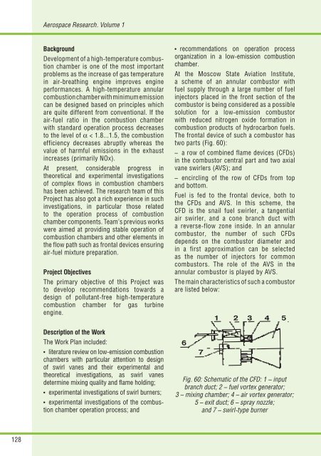
The frontal device of such a combustor has<br />
two parts (Fig. 60):<br />
– a row of combined flame devices (CFDs)<br />
in the combustor central part and two axial<br />
vane swirlers (AVS); and<br />
– encircling of the row of CFDs from top<br />
and bottom.<br />
Fuel is fed to the frontal device, both to<br />
the CFDs and AVS. In this scheme, the<br />
CFD is the snail fuel swirler, a tangential<br />
air swirler, and a cone branch duct with<br />
a reverseflow zone inside. In an annular<br />
combustor, the number of such CFDs<br />
depends on the combustor diameter and<br />
in a first approximation can be selected<br />
as the number of injectors for common<br />
combustors. The role of the AVS in the<br />
annular combustor is played by AVS.<br />
The main characteristics of such a combustor<br />
are listed below:<br />
Fig. 60: Schematic of the CFD: 1 – input<br />
branch duct; 2 – fuel vortex generator;<br />
3 – mixing chamber; 4 – air vortex generator;<br />
5 – exit duct; 6 – spray nozzle;<br />
and 7 – swirl-type burner