Operation Manual Transmitter M800 Multiparameter - Mettler Toledo
Operation Manual Transmitter M800 Multiparameter - Mettler Toledo
Operation Manual Transmitter M800 Multiparameter - Mettler Toledo

You also want an ePaper? Increase the reach of your titles
YUMPU automatically turns print PDFs into web optimized ePapers that Google loves.
<strong>Operation</strong> <strong>Manual</strong><br />
Multi-parameter<br />
<strong>Transmitter</strong> <strong>M800</strong><br />
<strong>Transmitter</strong> Multi-parameter <strong>M800</strong><br />
52 121 825
© 06 / 2012 <strong>Mettler</strong>-<strong>Toledo</strong> AG, CH-8606 Greifensee, Switzerland <strong>Transmitter</strong> <strong>M800</strong><br />
Printed in Switzerland 52 121 825
<strong>Operation</strong> <strong>Manual</strong><br />
Multi-parameter<br />
<strong>Transmitter</strong> <strong>M800</strong><br />
© 06 / 2012 <strong>Mettler</strong>-<strong>Toledo</strong> AG, CH-8606 Greifensee, Switzerland <strong>Transmitter</strong> <strong>M800</strong><br />
Printed in Switzerland 52 121 825
<strong>Transmitter</strong> <strong>M800</strong> 4<br />
© 06 / 2012 <strong>Mettler</strong>-<strong>Toledo</strong> AG, CH-8606 Greifensee, Switzerland <strong>Transmitter</strong> <strong>M800</strong><br />
Printed in Switzerland 52 121 825
<strong>Transmitter</strong> <strong>M800</strong> 5<br />
Content<br />
1 Introduction ___________________________________________________________________________________________ 9<br />
2 Safety instructions _____________________________________________________________________________________ 10<br />
2.1 Definition of equipment and documentation symbols and designations _______________________________________ 10<br />
2.2 Correct disposal of the unit ________________________________________________________________________ 11<br />
3 Unit overview _________________________________________________________________________________________ 12<br />
3.1 Overview _______________________________________________________________________________________ 12<br />
3.2 Display ________________________________________________________________________________________ 13<br />
3.2.1 Start Screen _____________________________________________________________________________ 13<br />
3.2.2 Activation Menu Screen ____________________________________________________________________ 13<br />
3.3 Graphic Trend Measurement ________________________________________________________________________ 14<br />
3.3.1 Activation Trend Display Screen ______________________________________________________________ 14<br />
3.3.2 Settings for Trend Display Screen _____________________________________________________________ 15<br />
3.3.3 Deactivation Trend Display Screen ____________________________________________________________ 15<br />
3.4 Control / Navigation _______________________________________________________________________________ 16<br />
3.4.1 Menu Structure ___________________________________________________________________________ 16<br />
3.4.2 Navigation ______________________________________________________________________________ 17<br />
3.4.2.1 Enter the Main Menus ____________________________________________________________ 17<br />
3.4.2.2 Navigating the Menu Tree _________________________________________________________ 18<br />
3.4.2.3 Exit a Menu ____________________________________________________________________ 18<br />
3.4.2.4 Confirm Data and Values _________________________________________________________ 18<br />
3.4.2.5 Return to the Menu Screen ________________________________________________________ 18<br />
3.4.3 Entry of Data ____________________________________________________________________________ 18<br />
3.4.4 Selection Menus __________________________________________________________________________ 18<br />
3.4.5 ”Save changes” Dialog ____________________________________________________________________ 18<br />
3.4.6 Security Passwords _______________________________________________________________________ 19<br />
3.4.7 Display ________________________________________________________________________________ 19<br />
4 Installation instruction __________________________________________________________________________________ 20<br />
4.1 Unpacking and inspection of equipment _______________________________________________________________ 20<br />
4.1.1 Panel cutout dimensional information ________________________________________________________ 20<br />
4.1.2 Installation procedure _____________________________________________________________________ 21<br />
4.1.3 Assembly _______________________________________________________________________________ 21<br />
4.1.4 Dimension drawings ______________________________________________________________________ 22<br />
4.1.5 Pipe mounting ___________________________________________________________________________ 22<br />
4.2 Connection of power supply ________________________________________________________________________ 23<br />
4.3 Terminal Definition _______________________________________________________________________________ 24<br />
4.3.1 <strong>M800</strong> 2-channel _________________________________________________________________________ 24<br />
4.3.2 <strong>M800</strong> 4-channel _________________________________________________________________________ 25<br />
4.3.3 TB2 and TB4 – Terminal Assignment for Optical Oxygen Sensor, CO2 hi, and UniCond2e _________________ 26<br />
4.3.4 TB2 and TB4 – Terminal Assignment for pH, Amp. Oxygen, Cond 4e, CO2 and O3 Sensors _______________ 26<br />
4.3.5 TB3 – Terminal Assignment for Flow Sensors ___________________________________________________ 27<br />
4.4 Connection of Flow Sensor _________________________________________________________________________ 27<br />
4.4.1 Flow Sensor Input Wiring Kit ________________________________________________________________ 27<br />
4.4.2 Kit Contents _____________________________________________________________________________ 28<br />
4.4.3 Flow sensor wiring for Compatible Sensors _____________________________________________________ 28<br />
4.4.4 Wiring for ”HIGH” type flow sensors __________________________________________________________ 28<br />
4.4.5 Wiring for ”LOW” type flow sensors ___________________________________________________________ 31<br />
4.4.6 Wiring for ”TYPE 2” flow sensors _____________________________________________________________ 31<br />
5 Placing transmitter in, or out, of service ___________________________________________________________________ 32<br />
5.1 Placing transmitter in service _______________________________________________________________________ 32<br />
5.2 Placing transmitter out of service ____________________________________________________________________ 32<br />
6 Guided Setup _________________________________________________________________________________________ 33<br />
7 Calibration ___________________________________________________________________________________________ 34<br />
7.1 Sensor Calibration ________________________________________________________________________________ 34<br />
7.2 Calibration of UniCond2e Sensors ___________________________________________________________________ 34<br />
7.2.1 Conductivity Calibration of UniCond2e Sensors __________________________________________________ 34<br />
7.2.1.1 One-Point Calibration ____________________________________________________________ 36<br />
7.2.1.2 Two-Point Calibration ____________________________________________________________ 37<br />
7.2.1.3 Process Calibration _____________________________________________________________ 38<br />
7.2.2 Temperature Calibration of UniCond2e Sensors __________________________________________________ 39<br />
7.2.2.1 One-Point Calibration ____________________________________________________________ 39<br />
7.2.2.2 Two-Point Calibration ____________________________________________________________ 40<br />
© 06 / 2012 <strong>Mettler</strong>-<strong>Toledo</strong> AG, CH-8606 Greifensee, Switzerland <strong>Transmitter</strong> <strong>M800</strong><br />
Printed in Switzerland 52 121 825
<strong>Transmitter</strong> <strong>M800</strong> 6<br />
7.3 Calibration of Cond4e Sensors ______________________________________________________________________ 42<br />
7.3.1 One-Point Calibration _____________________________________________________________________ 42<br />
7.3.2 Two-Point Calibration _____________________________________________________________________ 43<br />
7.3.3 Process Calibration _______________________________________________________________________ 43<br />
7.4 pH Calibration ___________________________________________________________________________________ 44<br />
7.4.1 One-Point Calibration _____________________________________________________________________ 44<br />
7.4.2 Two-Point Calibration _____________________________________________________________________ 45<br />
7.4.3 Process Calibration _______________________________________________________________________ 45<br />
7.5 ORP Calibration of pH Sensors ______________________________________________________________________ 46<br />
7.6 Calibration of Amperometric Oxygen Sensors ___________________________________________________________ 46<br />
7.6.1 One-Point Calibration _____________________________________________________________________ 47<br />
7.6.2 Process Calibration _______________________________________________________________________ 47<br />
7.7 Calibration of Optical Oxygen Sensors ________________________________________________________________ 48<br />
7.7.1 One-Point Calibration _____________________________________________________________________ 48<br />
7.7.2 Two-Point Calibration _____________________________________________________________________ 49<br />
7.7.3 Process Calibration _______________________________________________________________________ 50<br />
7.8 Calibration of Dissolved Carbon Dioxide Sensors ________________________________________________________ 50<br />
7.8.1 One-Point Calibration _____________________________________________________________________ 50<br />
7.8.2 Two-Point Calibration _____________________________________________________________________ 51<br />
7.8.3 Process Calibration _______________________________________________________________________ 52<br />
7.9 Calibration of Thermal Conductivity CO2 (C02 high) Sensors ______________________________________________ 52<br />
7.9.1 One-Point Calibration ______________________________________________________________________ 53<br />
7.9.2 Process Calibration _______________________________________________________________________ 53<br />
7.10 Calibration of O3 Sensors __________________________________________________________________________ 54<br />
7.10.1 One-Point Calibration _____________________________________________________________________ 54<br />
7.10.2 Process Calibration _______________________________________________________________________ 55<br />
7.11 Calibration of Flow Sensors ________________________________________________________________________ 56<br />
7.11.1 One-Point Calibration _____________________________________________________________________ 56<br />
7.11.2 Two-Point Calibration _____________________________________________________________________ 57<br />
7.12 Sensor Verification ________________________________________________________________________________ 58<br />
7.13 Edit Calibration Constants for Flow Sensors ____________________________________________________________ 59<br />
7.14 UniCond2e Electronics Calibration ___________________________________________________________________ 59<br />
7.15 Flow Meter Calibration ____________________________________________________________________________ 60<br />
7.16 Flow Meter Verification ____________________________________________________________________________ 61<br />
7.17 Analog Output Calibration __________________________________________________________________________ 61<br />
7.18 Analog Input Calibration ___________________________________________________________________________ 62<br />
7.19 Maintenance ____________________________________________________________________________________ 62<br />
8 Configuration _________________________________________________________________________________________ 63<br />
8.1 Measurement ___________________________________________________________________________________ 63<br />
8.1.1 Channel Setup ___________________________________________________________________________ 63<br />
8.1.2 Derived Measurements ____________________________________________________________________ 64<br />
8.1.2.1 % Rejection measurement ________________________________________________________ 65<br />
8.1.2.2 Calculated pH (Power Plant Applications only) ________________________________________ 65<br />
8.1.2.3 Calculated CO 2 (Power plant applications only) ________________________________________ 66<br />
8.1.3 Display Mode ____________________________________________________________________________ 66<br />
8.1.4 Parameter related Settings __________________________________________________________________ 67<br />
8.1.4.1 Conductivity Settings _____________________________________________________________ 67<br />
8.1.4.2 pH Settings ____________________________________________________________________ 68<br />
8.1.4.3 Settings for Oxygen Measurement Based on Amperometric Sensors _________________________ 69<br />
8.1.4.4 Settings for Oxygen Measurement Based on Optical Sensors ______________________________ 70<br />
8.1.4.5 Dissolved Carbon Dioxide Settings __________________________________________________ 71<br />
8.1.4.6 Settings for Thermal Conductivity Dissolved CO2 Measurement (CO2 hi) ____________________ 72<br />
8.1.4.7 Settings for TOC Measurement _____________________________________________________ 72<br />
8.1.4.8 Settings for Flow Measurement _____________________________________________________ 73<br />
8.1.4.9 Deionization Capacity (DI-Cap) __________________________________________________ 73<br />
8.1.5 Concentration Curve Table __________________________________________________________________ 74<br />
8.2 Analog Outputs __________________________________________________________________________________ 75<br />
8.3 Set Points ______________________________________________________________________________________ 76<br />
8.4 ISM Setup ______________________________________________________________________________________ 77<br />
8.4.1 Sensor Monitor ___________________________________________________________________________ 77<br />
8.4.2 CIP Cycle Limit ___________________________________________________________________________ 78<br />
8.4.3 SIP Cycle Limit ___________________________________________________________________________ 79<br />
8.4.4 AutoClave Cycle Limit _____________________________________________________________________ 80<br />
8.4.5 DLI Stress Adjustment _____________________________________________________________________ 81<br />
8.4.6 SAN Cycle Parameters _____________________________________________________________________ 81<br />
8.4.7 Reset Counters for UniCond2e Sensors ________________________________________________________ 82<br />
8.4.8 Set Calibration Interval for UniCond2e Sensors __________________________________________________ 82<br />
© 06 / 2012 <strong>Mettler</strong>-<strong>Toledo</strong> AG, CH-8606 Greifensee, Switzerland <strong>Transmitter</strong> <strong>M800</strong><br />
Printed in Switzerland 52 121 825
<strong>Transmitter</strong> <strong>M800</strong> 7<br />
8.5 General Alarm ___________________________________________________________________________________ 83<br />
8.6 ISM / Sensor Alarm _______________________________________________________________________________ 83<br />
8.7 Clean _________________________________________________________________________________________ 84<br />
8.8 Display Setup ___________________________________________________________________________________ 84<br />
8.9 Digital Inputs ____________________________________________________________________________________ 85<br />
8.10 System ________________________________________________________________________________________ 85<br />
8.11 PID Controller ___________________________________________________________________________________ 86<br />
8.12 Service ________________________________________________________________________________________ 90<br />
8.12.1 Set Analog Outputs _______________________________________________________________________ 90<br />
8.12.2 Read Analog Outputs _____________________________________________________________ 90<br />
8.12.3 Read Analog Inputs _______________________________________________________________________ 90<br />
8.12.4 Set Relay _______________________________________________________________________________ 90<br />
8.12.5 Read Relay _____________________________________________________________________________ 90<br />
8.12.6 Read Digital Inputs _______________________________________________________________________ 90<br />
8.12.7 Memory ________________________________________________________________________________ 91<br />
8.12.8 Display ________________________________________________________________________________ 91<br />
8.12.9 Calibrate TouchPad _______________________________________________________________________ 91<br />
8.12.10 Channel Diagnostic _______________________________________________________________________ 91<br />
8.13 Technical Service ________________________________________________________________________________ 91<br />
8.14 User Management ________________________________________________________________________________ 92<br />
8.15 Reset __________________________________________________________________________________________ 92<br />
8.15.1 System Reset ____________________________________________________________________________ 92<br />
8.15.2 Reset Sensor Calibration for Optical DO Sensors _________________________________________________ 93<br />
8.15.3 Reset Sensor Calibration for UniCond2e Sensors _________________________________________________ 93<br />
8.15.4 Reset Total Flow __________________________________________________________________________ 93<br />
8.15.5 Reset for CO2 hi Measurement ______________________________________________________________ 94<br />
8.16 RS485 Printer Output Configuration __________________________________________________________________ 94<br />
8.17 USB Measurement Interface ________________________________________________________________________ 95<br />
9 ISM _________________________________________________________________________________________________ 96<br />
9.1 iMonitor ________________________________________________________________________________________ 96<br />
9.2 Messages ______________________________________________________________________________________ 97<br />
9.3 ISM Diagnostics _________________________________________________________________________________ 97<br />
9.3.1 pH/ORP, Oxygen, O3 and Cond4e Sensors _____________________________________________________ 98<br />
9.3.2 UniCond2e Sensors _______________________________________________________________________ 98<br />
9.4 Calibration Data _________________________________________________________________________________ 99<br />
9.4.1 Calibration Data for All ISM Sensors excluding UniCond2e _________________________________________ 99<br />
9.4.2 Calibration Data for UniCond2e Sensors ______________________________________________________ 100<br />
9.5 Sensor Info ____________________________________________________________________________________ 100<br />
9.6 HW / SW Version _______________________________________________________________________________ 101<br />
9.7 Log Book _____________________________________________________________________________________ 101<br />
10 Wizards _____________________________________________________________________________________________ 102<br />
10.1 Set Wizard ____________________________________________________________________________________ 102<br />
10.2 Access to Wizards ______________________________________________________________________________ 102<br />
11 Maintenance _________________________________________________________________________________________ 103<br />
11.1 Front panel cleaning _____________________________________________________________________________ 103<br />
12 Troubleshooting ______________________________________________________________________________________ 104<br />
12.1 Warning- and Alarm Indication _____________________________________________________________________ 104<br />
12.1.1 Warning Indication_______________________________________________________________________ 104<br />
12.1.2 Alarm Indication _________________________________________________________________________ 105<br />
13 Accessories and Spare Parts ____________________________________________________________________________ 106<br />
14 Specifications ________________________________________________________________________________________ 107<br />
14.1 General specifications ___________________________________________________________________________ 107<br />
14.2 Electrical specifications ___________________________________________________________________________ 109<br />
14.3 Mechanical specifications _________________________________________________________________________ 109<br />
14.4 Environmental specifications ______________________________________________________________________ 110<br />
15 Warranty ____________________________________________________________________________________________ 111<br />
16 Buffer tables _________________________________________________________________________________________ 112<br />
16.1 Standard pH buffers _____________________________________________________________________________ 112<br />
16.1.1 <strong>Mettler</strong>-9 _______________________________________________________________________________ 112<br />
16.1.2 <strong>Mettler</strong>-10 _____________________________________________________________________________ 113<br />
16.1.3 NIST Technical Buffers ____________________________________________________________________ 113<br />
16.1.4 NIST standard buffers (DIN and JIS 19266: 2000–01) __________________________________________ 114<br />
16.1.5 Hach buffers ___________________________________________________________________________ 114<br />
© 06 / 2012 <strong>Mettler</strong>-<strong>Toledo</strong> AG, CH-8606 Greifensee, Switzerland <strong>Transmitter</strong> <strong>M800</strong><br />
Printed in Switzerland 52 121 825
<strong>Transmitter</strong> <strong>M800</strong> 8<br />
16.1.6 Ciba (94) buffers ________________________________________________________________________ 115<br />
16.1.7 Merck Titrisole, Riedel-de-Haën Fixanale _____________________________________________________ 115<br />
16.1.8 WTW buffers ___________________________________________________________________________ 116<br />
16.1.9 JIS Z 8802 buffers _______________________________________________________________________ 116<br />
16.2 Dual membrane pH electrode buffers ________________________________________________________________ 117<br />
16.2.1 <strong>Mettler</strong>-pH / pNa buffers (Na+ 3.9M) _________________________________________________________ 117<br />
© 06 / 2012 <strong>Mettler</strong>-<strong>Toledo</strong> AG, CH-8606 Greifensee, Switzerland <strong>Transmitter</strong> <strong>M800</strong><br />
Printed in Switzerland 52 121 825
<strong>Transmitter</strong> <strong>M800</strong> 9<br />
1 Introduction<br />
Statement of Intended Use – The <strong>M800</strong> multiparameter transmitter is a multi-channel online process<br />
instrument for measuring various properties of fluids and gases. These include Conductivity,<br />
Dissolved Oxygen, O2 gas, dissolved Ozone, dissolved carbon dioxide, pH / ORP and Flow.<br />
The <strong>M800</strong> is available in four different versions. The version indicates the amount of measurement<br />
parameters which can be covered and the kind of parameter. The version are indicated<br />
through there part numbers on the label of the transmitter.<br />
The <strong>M800</strong> transmitter is compatible with (digital) ISM and flow sensors.<br />
<strong>M800</strong> parameter fit guide<br />
Version Water 2-ch Water 4-ch Process 2-ch Process 4-ch<br />
Part no. 58 000 802 58 000 804 52 121 813 52 121 853<br />
pH / ORP • • • •<br />
pH / pNa – – • •<br />
UniCond2e • • • •<br />
Cond4e • • • •<br />
Amp. DO ppm/ppb/trace •/–/–* •/–/–* •/•/•** •/•/•**<br />
Amp. O2 gas ppm/ppb/trace •/–/–* •/–/–* •/•/•** •/•/•**<br />
Optical DO – – •*** •***<br />
Dissolved Carbon Dioxed – – • •<br />
CO2 hi (thermal conducivity) – – •*** •***<br />
TOC • • – –<br />
Dissolved O3 • • – –<br />
Flow • • – –<br />
* THORNTON sensors<br />
** INGOLD sensors<br />
*** One (two) optical DO or thermal conductivity CO2 sensor(s) can be used together with<br />
2-channel (4-channel) transmitter <strong>M800</strong>.<br />
A colored touch screen conveys measuring data and setup information. The menu structure allows<br />
the operator to modify all operational parameters by using the touch screen. A menu-lockout<br />
feature, with password protection, is available to prevent the unauthorized use of the meter.<br />
The <strong>M800</strong> <strong>Multiparameter</strong> transmitter can be configured to use up to eight analog and / or up to<br />
eight relay outputs for process control.<br />
The <strong>M800</strong> <strong>Multiparameter</strong> transmitter is equipped with a USB communication interface. This interface<br />
provides up- and download capabilities of the transmitter configuration via a Personal<br />
Computer (PC).<br />
This description corresponds to the firmware release, version 1.2 for the transmitter<br />
<strong>M800</strong> Water 2-channel, <strong>M800</strong> Process 2-channel, <strong>M800</strong> Water 4-channel and <strong>M800</strong> Process<br />
4-channel. Changes are taking place constantly, without prior notification.<br />
© 06 / 2012 <strong>Mettler</strong>-<strong>Toledo</strong> AG, CH-8606 Greifensee, Switzerland <strong>Transmitter</strong> <strong>M800</strong><br />
Printed in Switzerland 52 121 825
<strong>Transmitter</strong> <strong>M800</strong> 10<br />
a<br />
a<br />
h<br />
a<br />
a<br />
2 Safety instructions<br />
This manual includes safety information with the following designations and formats.<br />
2.1 Definition of equipment<br />
and documentation symbols and designations<br />
WARNING: POTENTIAL FOR PERSONAL INJURY.<br />
CAUTION: possible instrument damage or malfunction.<br />
NOTE: Important operating information.<br />
On the transmitter or in this manual text indicates: Caution and / or other possible hazard including<br />
risk of electric shock (refer to accompanying documents)<br />
The following is a list of general safety instructions and warnings. Failure to adhere to these instructions<br />
can result in damage to the equipment and / or personal injury to the operator.<br />
– The <strong>M800</strong> <strong>Transmitter</strong> should be installed and operated only by personnel familiar with<br />
the transmitter and who are qualified for such work.<br />
– The <strong>M800</strong> <strong>Transmitter</strong> must only be operated under the specified operating conditions<br />
(see chapter 14 “Specifications”).<br />
– Repair of the <strong>M800</strong> <strong>Transmitter</strong> must be performed by authorized, trained personnel only.<br />
– With the exception of routine maintenance, cleaning procedures or fuse replacement, as described<br />
in this manual, the <strong>M800</strong> <strong>Transmitter</strong> must not be tampered with or altered in<br />
any manner.<br />
– <strong>Mettler</strong>-<strong>Toledo</strong> accepts no responsibility for damage caused by unauthorized modifications<br />
to the transmitter.<br />
– Follow all warnings, cautions, and instructions indicated on and supplied with this product.<br />
– Install equipment as specified in this instruction manual. Follow appropriate local and national<br />
codes.<br />
– Protective covers must be in place at all times during normal operation.<br />
– If this equipment is used in a manner not specified by the manufacturer, the protection provided<br />
by it against hazards may be impaired.<br />
WARNINGS:<br />
– Installation of cable connections and servicing of this product require access to shock hazard<br />
voltage levels.<br />
– Main power and relay contacts wired to separate power source must be disconnected before<br />
servicing.<br />
– Switch or circuit breaker shall be in close proximity to the equipment and within easy reach<br />
of the OPERATOR; it shall be marked as the disconnecting device for the equipment.<br />
– Main power must employ a switch or circuit breaker as the disconnecting device for the<br />
equipment.<br />
– Electrical installation must be in accordance with the National Electrical Code and / or any<br />
other applicable national or local codes.<br />
© 06 / 2012 <strong>Mettler</strong>-<strong>Toledo</strong> AG, CH-8606 Greifensee, Switzerland <strong>Transmitter</strong> <strong>M800</strong><br />
Printed in Switzerland 52 121 825
<strong>Transmitter</strong> <strong>M800</strong> 11<br />
h<br />
h<br />
h<br />
NOTE: RELAY CONTROL ACTION<br />
the <strong>M800</strong> transmitter relays will always de-energize on loss of power, equivalent to normal<br />
state, regardless of relay state setting for powered operation. Configure any control<br />
system using these relays with fail-safe logic accordingly.<br />
NOTE: PROCESS UPSETS<br />
Because process and safety conditions may depend on consistent operation of this transmitter,<br />
provide appropriate means to maintain operation during sensor cleaning, replacement<br />
or sensor or instrument calibration.<br />
NOTE: This is a 4-wire-product with an active 4–20 mA analog output.<br />
Please do not supply to terminal 3 to 10 of TB1 and terminal 1 to 8 of TB3.<br />
2.2 Correct disposal of the unit<br />
When the transmitter is finally removed from service, observe all local environmental regulations<br />
for proper disposal.<br />
© 06 / 2012 <strong>Mettler</strong>-<strong>Toledo</strong> AG, CH-8606 Greifensee, Switzerland <strong>Transmitter</strong> <strong>M800</strong><br />
Printed in Switzerland 52 121 825
<strong>Transmitter</strong> <strong>M800</strong> 12<br />
3 Unit overview<br />
The <strong>M800</strong> models are available in 1/2DIN case size. The <strong>M800</strong> models provide an integral<br />
IP66 housing for wall- or pipe mount.<br />
3.1 Overview<br />
METTLER TOLEDO<br />
150 mm/5.90"<br />
1<br />
2<br />
<strong>M800</strong><br />
© 06 / 2012 <strong>Mettler</strong>-<strong>Toledo</strong> AG, CH-8606 Greifensee, Switzerland <strong>Transmitter</strong> <strong>M800</strong><br />
Printed in Switzerland 52 121 825<br />
158 mm/6.22"<br />
1: Hard Polycarbonate case<br />
2: VGA Screen<br />
3: Power Supply Terminals<br />
4: Relay Output Terminals<br />
5: Analog Output / Digital Input Terminals<br />
6: Sensor Input Terminals<br />
5<br />
TB1<br />
TB2<br />
TB3 TB4 TB5<br />
TB6<br />
6 6 3<br />
4
<strong>Transmitter</strong> <strong>M800</strong> 13<br />
3.2 Display<br />
3.2.1 Start Screen<br />
After starting the <strong>M800</strong>, the following Start Screen (logout screen) is shown automatically. To return<br />
form the Menu Screen to the Start Screen press s. The <strong>M800</strong> will return automatically after<br />
240 seconds from the Menu Screen or any configuration screen to the Start Screen if the user<br />
has not pressed the touch screen.<br />
3.2.2 Activation Menu Screen<br />
While the <strong>M800</strong> shows the Start Screen (logout screen) touch the display to activate the Menu<br />
Screen. To return to the Menu Screen from other menus press H.<br />
© 06 / 2012 <strong>Mettler</strong>-<strong>Toledo</strong> AG, CH-8606 Greifensee, Switzerland <strong>Transmitter</strong> <strong>M800</strong><br />
Printed in Switzerland 52 121 825
<strong>Transmitter</strong> <strong>M800</strong> 14<br />
3.3 Graphic Trend Measurement<br />
Any single measurement may be displayed as a trend measurement over time. Measurement<br />
values will be indicated by a value on the Y axis and time elapsed on the X axis of the graph<br />
displayed. An actual measurement for the selected value will also display numerically above<br />
the graphic trend display. The measurement value is refreshed once per second.<br />
Graphic trending will only display the data within maximum/minimum range. Out of range values<br />
or invalid values will not be displayed. The Y axis will display the maximum value unit with<br />
its range; X axis unit uses “mins” for minutes for measurements less than one hour and “hrs” for<br />
one day. 4 scales for X/Y axis. The maximum value on Y-axis is one decimal place.<br />
3.3.1 Activation Trend Display Screen<br />
While the <strong>M800</strong> displays the Menu Screen, touch any measurement value line of the display<br />
screen twice (1-chan, 2-chan, 4-meas, 8-meas) to activate the trend display for that measurement.<br />
If a sensor is disconnect/connect pop-up window come up, after close it will go back to the<br />
Menu Screen.<br />
Red/yellow bar on top line will display for any message occuring during trending. ‘H’, ‘P’,”AB”<br />
will display when this channel is in hold or process.<br />
© 06 / 2012 <strong>Mettler</strong>-<strong>Toledo</strong> AG, CH-8606 Greifensee, Switzerland <strong>Transmitter</strong> <strong>M800</strong><br />
Printed in Switzerland 52 121 825
<strong>Transmitter</strong> <strong>M800</strong> 15<br />
h<br />
h<br />
h<br />
3.3.2 Settings for Trend Display Screen<br />
For setting configurations, touch any area of the graphic trend display to go to the pop-up window<br />
of this meaurement parameter. Settings are at the default values. However, these settings<br />
may be changed when options are available, as needed.<br />
Time: option button. For graphic display time (X axis)<br />
1-h (default value)<br />
1-day<br />
NOTE: 1 h means: 1 meas storage/15 seconds, totally 240 measurements for 1h. 1 day<br />
means: 1 meas storage/6 minutes, totally 240 measurements for 1 day;<br />
Range: option button<br />
Default(default value)<br />
Individual<br />
When “Default” modes are set for the maximum or minimum value, this indicates the full measurement<br />
range for this unit. A Max or Min button is not displayed. If setting is selectable, the<br />
user can set maximum and minimum settings manually.<br />
Max: Edit button.<br />
Maximum value of this unit on Y axis. xxxxxx, floating decimal point.<br />
Min: Edit button.<br />
Minimum value of this unit on Y axis. xxxxxx, floating decimal point.<br />
Max Value > Min Value<br />
NOTE: Settings for y- and x-axis and the corresponding measurement values are stored the<br />
transmitters memory. A power down returns to default settings.<br />
3.3.3 Deactivation Trend Display Screen<br />
Press H in activated graphic trend screen to return to Menu Screen.<br />
NOTE: If a sensor is disconnect/connect pop-up window come up, after close it will go back to<br />
the Menu Screen.<br />
© 06 / 2012 <strong>Mettler</strong>-<strong>Toledo</strong> AG, CH-8606 Greifensee, Switzerland <strong>Transmitter</strong> <strong>M800</strong><br />
Printed in Switzerland 52 121 825
<strong>Transmitter</strong> <strong>M800</strong> 16<br />
3.4 Control / Navigation<br />
3.4.1 Menu Structure<br />
Below is the structure of the <strong>M800</strong> menu tree:<br />
i<br />
iMonitor<br />
Messages<br />
ISM Diagnostics<br />
Calibration Data<br />
Sensor Info<br />
HW/SW Version<br />
Log Book<br />
S<br />
Wizard<br />
Favorite 1…4<br />
Set Wizard<br />
Menu Screen<br />
<strong>M800</strong><br />
c<br />
Calibration<br />
Calibration Sensor<br />
Calibrate Electronics<br />
Calibrate Meter<br />
Calibrate<br />
Analog Outputs<br />
Calibrate<br />
Analog Inputs<br />
Maintenance<br />
C<br />
Configuration<br />
Guided Setup<br />
Measurement<br />
Analog Outputs<br />
Set Points<br />
ISM Setup<br />
General Alarm<br />
ISM/Sensor Alarm<br />
Display Setup<br />
Digital Inputs<br />
© 06 / 2012 <strong>Mettler</strong>-<strong>Toledo</strong> AG, CH-8606 Greifensee, Switzerland <strong>Transmitter</strong> <strong>M800</strong><br />
Printed in Switzerland 52 121 825<br />
Clean<br />
System<br />
PID Controller<br />
Service<br />
Tech Service<br />
User Management<br />
Reset<br />
Printer<br />
Channel Setup<br />
Display Mode<br />
Parameter Setting<br />
Concentration<br />
Curve Table
<strong>Transmitter</strong> <strong>M800</strong> 17<br />
i<br />
S<br />
c<br />
C<br />
3.4.2 Navigation<br />
3.4.2.1 Enter the Main Menus<br />
Activate the Menu Screen and press one of icons to enter the different main menus:<br />
ISM menu<br />
Wizard menu<br />
Calibration menu<br />
Configuration menu<br />
© 06 / 2012 <strong>Mettler</strong>-<strong>Toledo</strong> AG, CH-8606 Greifensee, Switzerland <strong>Transmitter</strong> <strong>M800</strong><br />
Printed in Switzerland 52 121 825
<strong>Transmitter</strong> <strong>M800</strong> 18<br />
h<br />
h<br />
3.4.2.2 Navigating the Menu Tree<br />
To browse through the menus, press the open arrows > and/or
<strong>Transmitter</strong> <strong>M800</strong> 19<br />
h<br />
h<br />
3.4.6 Security Passwords<br />
The <strong>M800</strong> transmitter allows a security lock-out of various menus. If the security lock-out<br />
feature of the transmitter has been enabled, a security password must be entered to allow access<br />
to the menu. See chapter 8.14 “User Management”.<br />
3.4.7 Display<br />
NOTE: In the event of an alarm or other error condition the <strong>M800</strong> <strong>Transmitter</strong> will display a flashing<br />
bar graph on the display. This bar graph will remain until the condition that caused it has<br />
been cleared (see chapter 12.1 “Warning- and Alarm Indication)”.<br />
NOTE: During calibrations, clean, Digital In with Analog Output / Relay / USB in Hold state, a<br />
flashing ”H” (Hold) will appear in the upper right corner of the display for the corresponding<br />
channel. This symbol will remain for 20 sec., after end of calibration. This symbol will remain<br />
for 20 seconds until after the calibration or clean is completed. This symbol will also disappear<br />
when Digital In is deactivated.<br />
© 06 / 2012 <strong>Mettler</strong>-<strong>Toledo</strong> AG, CH-8606 Greifensee, Switzerland <strong>Transmitter</strong> <strong>M800</strong><br />
Printed in Switzerland 52 121 825
<strong>Transmitter</strong> <strong>M800</strong> 20<br />
4 Installation instruction<br />
4.1 Unpacking and inspection of equipment<br />
Inspect the shipping container. If it is damaged, contact the shipper immediately for instructions.<br />
Do not discard the box.<br />
If there is no apparent damage, unpack the container. Be sure all items shown on the packing<br />
list are present.<br />
If items are missing, notify <strong>Mettler</strong>-<strong>Toledo</strong> immediately<br />
4.1.1 Panel cutout dimensional information<br />
Below are cut-out dimensions required by the transmitter when mounted within a flat panel or on<br />
a flat enclosure door. This surface must be flat and smooth. Textured or rough surfaces are not<br />
recommended and may limit the effectiveness of the gasket seal provided.<br />
(+ 0.5 mm)<br />
(– 0 mm)<br />
137 mm<br />
(+ 0.02")<br />
(– 0")<br />
5.39"<br />
(+ 0.5 mm)<br />
137 mm<br />
(– 0 mm)<br />
(+ 0.02")<br />
5.39"<br />
(– 0")<br />
PANEL CUT-OUT<br />
Optional hardware accessories are available that allow for panel- or pipe-mount.<br />
Refer to chapter 13 “Accessories and Spare Parts” for ordering information.<br />
© 06 / 2012 <strong>Mettler</strong>-<strong>Toledo</strong> AG, CH-8606 Greifensee, Switzerland <strong>Transmitter</strong> <strong>M800</strong><br />
Printed in Switzerland 52 121 825
<strong>Transmitter</strong> <strong>M800</strong> 21<br />
4.1.2 Installation procedure<br />
General:<br />
– Orient the transmitter so that the cable grips face downward.<br />
– Wiring routed through the cable grips shall be suitable for use in wet locations.<br />
– In order provide IP66 enclosure ratings, all cable glands must be in place. Each cable gland<br />
must be filled using a cable, or suitable Cable Gland Hole Seal.<br />
For Pipe Mount:<br />
– Use only manufacturer-supplied components for pipe-mounting the <strong>M800</strong> transmitter and install<br />
per the supplied instructions. See chapter 13 “Accessories and Spare Parts” for ordering<br />
information.<br />
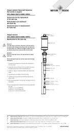
4.1.3 Assembly<br />
1: 3 M20x1.5 cable glands<br />
2: 2 M25x1.5 cable glands<br />
3: 4 screws<br />
© 06 / 2012 <strong>Mettler</strong>-<strong>Toledo</strong> AG, CH-8606 Greifensee, Switzerland <strong>Transmitter</strong> <strong>M800</strong><br />
Printed in Switzerland 52 121 825<br />
1<br />
2<br />
3
<strong>Transmitter</strong> <strong>M800</strong> 22<br />
4.1.4 Dimension drawings<br />
(+ 0.5 mm)<br />
(– 0 mm)<br />
137 mm<br />
45 mm/<br />
1.77"<br />
(+ 0.02")<br />
(– 0")<br />
5.39"<br />
137 mm<br />
5.39"<br />
170 mm/6.69"<br />
(+ 0.5 mm)<br />
(– 0 mm)<br />
(+ 0.02")<br />
(– 0")<br />
125 mm/4.92"<br />
4.1.5 Pipe mounting<br />
Ø 40 ... Ø 60 mm<br />
Ø 1.57... Ø 2.36"<br />
150 mm/5.90"<br />
© 06 / 2012 <strong>Mettler</strong>-<strong>Toledo</strong> AG, CH-8606 Greifensee, Switzerland <strong>Transmitter</strong> <strong>M800</strong><br />
Printed in Switzerland 52 121 825<br />
METTLER TOLEDO<br />
66 mm/2.59"<br />
40 mm/<br />
1.58"<br />
<strong>M800</strong><br />
25 mm<br />
0.98"<br />
35 mm<br />
1.38"<br />
158 mm/6.22"<br />
58 mm<br />
2.28"
<strong>Transmitter</strong> <strong>M800</strong> 23<br />
a<br />
4.2 Connection of power supply<br />
All connections to the transmitter are made on the inside of all models.<br />
Be sure power to all wires is turned off before proceeding with the installation<br />
A three-terminal connector on TB6 of all <strong>M800</strong> models is provided for power connection.<br />
All <strong>M800</strong> models are designed to operate from a 20–30 VDC or a 100 to 240 VAC power<br />
source. Refer to specifications for power requirements and ratings and size power wiring accordingly<br />
(16–24 AWG, wire cross-section between 0.2 mm 2 and 1.5 mm 2 ).<br />
The terminal block for power connections is labeled TB6 on the rear panel of the transmitter.<br />
One terminal is labeled N (–) for the Neutral wire and the other L (+) for the Line (or Load) wire.<br />
For DC power, use the polarity shown in parentheses.<br />
The terminals are suitable for single wires and flexible leads with a wire cross-section from<br />
0.2 mm 2 up to 1.5 mm 2 , (16–24 AWG).<br />
© 06 / 2012 <strong>Mettler</strong>-<strong>Toledo</strong> AG, CH-8606 Greifensee, Switzerland <strong>Transmitter</strong> <strong>M800</strong><br />
Printed in Switzerland 52 121 825
<strong>Transmitter</strong> <strong>M800</strong> 24<br />
h<br />
4.3 Terminal Definition<br />
4.3.1 <strong>M800</strong> 2-channel<br />
Power connections:<br />
N for Neutral and L for Line, for 100 to 240 VAC or 20–30 VDC.<br />
Terminal<br />
number<br />
TB1<br />
TB2<br />
(ISM Ch1,2)<br />
TB3 TB4 TB5 TB6<br />
1 DI1+ DI2+ Aout5+<br />
AI1+ L<br />
2 DI1– DI2– Aout5– AI1- N<br />
3 Aout1+ 1-Wire_Ch1 Aout6+ DI4+ Ground<br />
4 Aout1– GND5V_Ch1 Aout6– DI4– Relay1_NC<br />
5 Aout2+ RS485B_Ch1 Aout7+ DI5+ Relay1_COM<br />
6 Aout2– RS485A_Ch1 Aout7– DI5– Relay2_NO<br />
7 Aout3+ GND5V_Ch1 Aout8+ DI6+ Relay2_COM<br />
8 Aout3– 5V_Ch1 Aout8- DI6– Relay3_NO<br />
9 Aout4+ 24V_Ch2 Ain_Ch5 Relay5_NO Relay3_COM<br />
10 Aout4– GND24V_Ch2 AJ_Ch5 Relay5_COM Relay4_NO<br />
11 n. a. 1-Wire_Ch2 5V_Ch5 Relay6_NO Relay4_COM<br />
12 n. a. GND5V_Ch2 GND5V_Ch5 Relay6_COM n. a.<br />
13 n. a. RS485B_Ch2 Bin_Ch6 Relay7_NO n. a.<br />
14 n. a. RS485A_Ch2 BJ_Ch6 Relay7_COM n. a.<br />
15 n. a. GND5V_Ch2 5V_Ch6 Relay8_NC n. a.<br />
16 n. a. 5V_Ch2 GND5V_Ch6 Relay8_COM n. a.<br />
TB1<br />
TB2 TB3 TB4 TB5<br />
TB6<br />
Not installed<br />
NO: normally open (contact open if un-actuated). AO: Analog Output<br />
NC: normally closed (contact closed if un-actuated). DI: Digital Input<br />
Ain: AJ:<br />
Bin: BJ:<br />
n.a. not available<br />
NOTE: This is a 4-wire-product with an active 4–20 mA analog output.<br />
Please do not supply to terminal no. 3 to 10 of TB1 and 1 to 8 of TB3.<br />
© 06 / 2012 <strong>Mettler</strong>-<strong>Toledo</strong> AG, CH-8606 Greifensee, Switzerland <strong>Transmitter</strong> <strong>M800</strong><br />
Printed in Switzerland 52 121 825
<strong>Transmitter</strong> <strong>M800</strong> 25<br />
h<br />
4.3.2 <strong>M800</strong> 4-channel<br />
Power connections:<br />
N for Neutral and L for Line, for 100 to 240 VAC or 20–30 VDC.<br />
Terminal<br />
number<br />
TB1<br />
TB2<br />
(ISM Ch1,2)<br />
© 06 / 2012 <strong>Mettler</strong>-<strong>Toledo</strong> AG, CH-8606 Greifensee, Switzerland <strong>Transmitter</strong> <strong>M800</strong><br />
Printed in Switzerland 52 121 825<br />
TB3<br />
TB4<br />
(ISM Ch3,4)<br />
TB5 TB6<br />
1 DI1+ DI2+ Aout5+ DI3+ AI1+ L<br />
2 DI1– DI2– Aout5– DI3– AI1- N<br />
3 Aout1+ 1-Wire_Ch1 Aout6+ 1-Wire_Ch3 DI4+ Ground<br />
4 Aout1– GND5V_Ch1 Aout6– GND5V_Ch3 DI4– Relay1_NC<br />
5 Aout2+ RS485B_Ch1 Aout7+ RS485B_Ch3 DI5+ Relay1_COM<br />
6 Aout2– RS485A_Ch1 Aout7– RS485A_Ch3 DI5– Relay2_NO<br />
7 Aout3+ GND5V_Ch1 Aout8+ GND5V_Ch3 DI6+ Relay2_COM<br />
8 Aout3– 5V_Ch1 Aout8- 5V_Ch3 DI6– Relay3_NO<br />
9 Aout4+ 24V_Ch2 Ain_Ch5 24V_Ch4 Relay5_NO Relay3_COM<br />
10 Aout4– GND24V_Ch2 AJ_Ch5 GND24V_Ch4 Relay5_COM Relay4_NO<br />
11 n. a. 1-Wire_Ch2 5V_Ch5 1-Wire_Ch4 Relay6_NO Relay4_COM<br />
12 n. a. GND5V_Ch2 GND5V_Ch5 GND5V_Ch4 Relay6_COM n. a.<br />
13 n. a. RS485B_Ch2 Bin_Ch6 RS485B_Ch4 Relay7_NO n. a.<br />
14 n. a. RS485A_Ch2 BJ_Ch6 RS485A_Ch4 Relay7_COM n. a.<br />
15 n. a. GND5V_Ch2 5V_Ch6 GND5V_Ch4 Relay8_NC n. a.<br />
16 n. a. 5V_Ch2 GND5V_Ch6 5V_Ch4 Relay8_COM n. a.<br />
TB1<br />
TB2<br />
TB3 TB4 TB5<br />
TB6<br />
NO: normally open (contact open if un-actuated). AO: Analog Output<br />
NC: normally closed (contact closed if un-actuated). DI: Digital Input<br />
Ain: AJ:<br />
Bin: BJ:<br />
n.a. not available<br />
NOTE: This is a 4-wire-product with an active 4–20 mA analog output.<br />
Please do not supply to terminal no. 3 to 10 of TB1 and 1 to 8 of TB3.
<strong>Transmitter</strong> <strong>M800</strong> 26<br />
4.3.3 TB2 and TB4 – Terminal Assignment for<br />
Optical Oxygen Sensor, CO2 hi, and UniCond2e<br />
TB2<br />
(ISM Ch1, 2)<br />
TB4<br />
(ISM Ch3,4)<br />
Optical Oxygen*,<br />
CO2 hi*,<br />
UniCond2e**<br />
Terminal no. Function Function Sensor wire color Sensor wire color<br />
1 DI2+ DI6+ – –<br />
2 DI2– DI6- – –<br />
3 1-Wire_Ch1 1-Wire_Ch3 – –<br />
4 GND5V_Ch1 GND5V_Ch3 – –<br />
5 RS485B_Ch1 RS485B_Ch3 – black<br />
6 RS485A_Ch1 RS485A_Ch3 – red<br />
7 GND5V_Ch1 GND5V_Ch3 – white<br />
8 5V_Ch1 5V_Ch3 – blue<br />
9 24V_Ch2 24V_Ch4 brown –<br />
10 GND24V_Ch2 GND24V_Ch4 black –<br />
11 1-Wire_Ch2 1-Wire_Ch4 – –<br />
12 GND5V_Ch2 GND5V_Ch4 grey –<br />
13 RS485B_Ch2 RS485B_Ch4 blue black<br />
14 RS485A_Ch2 RS485A_Ch4 white red<br />
15 GND5V_Ch2 GND5V_Ch4 yellow white<br />
16 5V_Ch2 5V_Ch4 – blue<br />
* Always one O2 optical or thermal conductivity CO2 sensor can be connected to plug TB2<br />
and TB4.<br />
** Transparent wire not connected<br />
4.3.4 TB2 and TB4 – Terminal Assignment for pH,<br />
Amp. Oxygen, Cond 4e, CO2 and O3 Sensors<br />
TB2<br />
(ISM Ch1, 2)<br />
TB4<br />
(ISM Ch3,4)<br />
pH, amp. Oxygen, Cond 4e, CO2, and<br />
O3<br />
Terminal no. Function Function Sensor wire color<br />
1 DI2+ DI6+ –<br />
2 DI2– DI6– –<br />
3 1-Wire_Ch1 1-Wire_Ch3 transparent (cable core)<br />
4 GND5V_Ch1 GND5V_Ch3 red<br />
5 RS485B_Ch1 RS485B_Ch3 –<br />
6 RS485A_Ch1 RS485A_Ch3 –<br />
7 GND5V_Ch1 GND5V_Ch3 –<br />
8 5V_Ch1 5V_Ch3 –<br />
9 24V 24V –<br />
10 GND24V GND24V –<br />
11 1-Wire_Ch2 1-Wire_Ch4 transparent (cable core)<br />
12 GND5V_Ch2 GND5V_Ch4 red<br />
13 RS485B_Ch2 RS485B_Ch4 –<br />
14 RS485A_Ch2 RS485A_Ch4 –<br />
15 GND5V_Ch2 GND5V_Ch4 –<br />
16 5V_Ch2 5V_Ch4 –<br />
© 06 / 2012 <strong>Mettler</strong>-<strong>Toledo</strong> AG, CH-8606 Greifensee, Switzerland <strong>Transmitter</strong> <strong>M800</strong><br />
Printed in Switzerland 52 121 825
<strong>Transmitter</strong> <strong>M800</strong> 27<br />
4.3.5 TB3 – Terminal Assignment for Flow Sensors<br />
TB3 Flow hi, Flow lo, Flow Type2<br />
Terminal no. <strong>Transmitter</strong> Function<br />
1 Aout5+ –<br />
2 Aout5- –<br />
3 Aout6+ –<br />
4 Aout6- –<br />
5 Aout7+ –<br />
6 Aout7- –<br />
7 Aout8+ –<br />
8 Aout8- –<br />
9 Ain_Ch5 Flow Pulse Input<br />
10 AJ_Ch5 + 10 VDC<br />
11 5V_Ch5 + 5 VDC<br />
12 GND5V_Ch5 Ground<br />
13 Ain_Ch6 Flow Pulse Input<br />
14 AJ_Ch6 + 10 VDC<br />
15 5V_Ch6 + 5 VDC<br />
16 GND5V_Ch6 Ground<br />
4.4 Connection of Flow Sensor<br />
The <strong>M800</strong> transmitter is designed to operate with various types of sensors. These sensors require<br />
different wiring configurations. Listed below are instructions for wiring the various types of<br />
sensors offered by <strong>Mettler</strong>-<strong>Toledo</strong> THORNTON for use with this transmitter. Please consult the factory<br />
for assistance if attempting to wire sensors not offered by <strong>Mettler</strong>-<strong>Toledo</strong> Thornton as some<br />
sensors may not be compatible.<br />
4.4.1 Flow Sensor Input Wiring Kit<br />
This kit contains components that may be needed at input terminals to condition sensor signals.<br />
Refer to the following sections or to the instruction manual for wiring details.<br />
© 06 / 2012 <strong>Mettler</strong>-<strong>Toledo</strong> AG, CH-8606 Greifensee, Switzerland <strong>Transmitter</strong> <strong>M800</strong><br />
Printed in Switzerland 52 121 825
<strong>Transmitter</strong> <strong>M800</strong> 28<br />
4.4.2 Kit Contents<br />
This kit contains the following items:<br />
− 4x Wire nuts<br />
− 4x 10K ohm resistors for use with Burket 8020 and 8030 type sensors, and GF Signet<br />
2500-series sensors.<br />
− 4x 1K ohm resistors for use with Data Industrial 200-series and Fluidyne insertion type<br />
sensors.<br />
− 4x 0.33uF, 50 V capacitors for use with Berket 8020 and 8030 type sensors, Data Industrial<br />
200-series and 4000-series sensors, GF Signet 2500-series sensors, Sanitary Turbine-Type<br />
sensors, Fluidyne insertion type sensors and Racine Federated (Formerly Asahi/America) vortex-style<br />
sensors.<br />
4.4.3 Flow sensor wiring for Compatible Sensors<br />
The following sections provide wiring information to properly connect various compatible flow<br />
sensors to the <strong>M800</strong> transmitter. When using the Configuration menu of the transmitter to setup<br />
the flow sensor, the first prompt asks to select the TYPE of flow sensor being connected.<br />
There are three choices as follows:<br />
High: All flow sensors described in Section 4.4.4<br />
Low: P515 Signet flow sensors only, described in section 4.4.5<br />
Type 2: Asahi flow sensors, described in Section 4.4.6<br />
4.4.4 Wiring for ”HIGH” type flow sensors<br />
The following wiring information is used when connecting (Burkert 8020 and 8030 type) inline<br />
Hall effect 5VDC, flow sensors. Thornton models 33901 thru 33935.<br />
Burkert 8020, 8030<br />
Hall-Effect Sensor<br />
Type: high<br />
THORNTON 33901-33935<br />
58 034 601 - 58 034 635<br />
0.33uF<br />
Pulse output<br />
L+<br />
L–<br />
<strong>M800</strong> transmitter<br />
Extension cable not provided. Use 2-conductor twisted pair with shield, 22 AWG (Belden 8451<br />
or equivalent), 1,000 ft (305 m) maximum length.<br />
© 06 / 2012 <strong>Mettler</strong>-<strong>Toledo</strong> AG, CH-8606 Greifensee, Switzerland <strong>Transmitter</strong> <strong>M800</strong><br />
Printed in Switzerland 52 121 825<br />
10K<br />
TB 3<br />
9 Ain_Ch5<br />
10 AJ_Ch5<br />
11 5V_Ch5<br />
12 GND5V_Ch5
<strong>Transmitter</strong> <strong>M800</strong> 29<br />
The following wiring information is used when connecting Badger (formerly Data Industrial<br />
200-Series) forward-swept paddlewheel type flow sensors.<br />
Thornton models 33142 thru 33145 and 33159 thru 33162 and 33273.<br />
THORNTON 33142-33145<br />
58 034 201 - 58 034 204<br />
0.33uF<br />
Red<br />
Black<br />
Shield<br />
Badger<br />
(formerly Data Industrial 200 Series)<br />
Flow Sensors<br />
Type: High<br />
<strong>M800</strong> transmitter<br />
Extension cable provided with sensor. Use 2-conductor twisted pair with shield 20 AWG<br />
(Belden 9320 or equivalent) to extend length to 2000 ft (610 m) max.<br />
The following wiring information is used when connecting Badger (formerly Data Industrial<br />
4000-Series) forward-swept paddlewheel type flow sensors.<br />
Thornton models 33174 thru 33177 and 33171 and 33172.<br />
20 ft (6.1 m) extension cable provided with sensor. Use 3-conductor with shield,<br />
20 AWG (Belden 9364 or equivalent) to extend length to 2000 ft (610 m) maximum.<br />
The following wiring information is used when connecting (GF Signet 2500-Series) Hall Effect<br />
paddlewheel type flow sensors. Thornton models 33282, 33285, 33287, 33298 thru 33305.<br />
25 ft (7.6 m) extension cable provided with sensor. Use 2-conductor with shield,<br />
22 AWG (Belden 8451 or equivalent) to extend length to 1000 ft (305 m) maximum.<br />
© 06 / 2012 <strong>Mettler</strong>-<strong>Toledo</strong> AG, CH-8606 Greifensee, Switzerland <strong>Transmitter</strong> <strong>M800</strong><br />
Printed in Switzerland 52 121 825<br />
1K<br />
THORNTON 33174-33177, 33171, 33172<br />
58 034 207 - 58 034 211, 58 034 226<br />
Clear<br />
Red<br />
Black<br />
Shield<br />
Badger<br />
(formerly Data Industrial 4000 Series)<br />
Flow Sensors<br />
Type: High<br />
Signet 2507, 2536, 2540<br />
Hall-Effect Sensor<br />
Type: high<br />
0.33uF<br />
THORNTON 33282, 33285, 33287, 33298 - 33305<br />
58 034 227, 58 034 230, 58 034 232 - 58 034 240<br />
Red<br />
Black<br />
Shield<br />
10K<br />
0.33uF<br />
TB 3<br />
9 Ain_Ch5<br />
10 AJ_Ch5<br />
11 5V_Ch5<br />
12 GND5V_Ch5<br />
TB 3<br />
9 Ain_Ch5<br />
10 AJ_Ch5<br />
11 5V_Ch5<br />
12 GND5V_Ch5<br />
<strong>M800</strong> transmitter<br />
TB 3<br />
9 Ain_Ch5<br />
10 AJ_Ch5<br />
11 5V_Ch5<br />
12 GND5V_Ch5<br />
<strong>M800</strong> transmitter
<strong>Transmitter</strong> <strong>M800</strong> 30<br />
The following wiring information is used when connecting Sanitary Turbine type flow sensors.<br />
Thornton models 33336 thru 33377 (Hoffer) and 33441 thru 33450 (Sponsler).<br />
Hoffer Turbine Sensors<br />
Type: High<br />
THORNTON 3336-33348, 33376, 33377<br />
58 034 270 - 58 034 282, 58 034 303, 58 034 304<br />
White<br />
Red<br />
Black<br />
Shield<br />
<strong>M800</strong> transmitter<br />
20 ft (6.1 m) extension cable provided with sensor. Use 3-conductor with shield,<br />
20 AWG (Belden 9364 or equivalent) to extend length to 3000 ft (915 m) maximum.<br />
Sponsler Turbine Sensor<br />
Type: High<br />
Orange<br />
Red<br />
Black<br />
Shield<br />
20 ft (6.1 m) extension cable provided with sensor. Use 3-conductor with shield,<br />
20 AWG (Belden 9364 or equivalent) to extend length to 3000 ft (915 m) maximum.<br />
The following wiring information is used when connecting Spirax Sarco/Emco flow (formerly<br />
Fluidyne) insertion type flow sensors. Thornton models 33358 thru 33375.<br />
Spirax Sarco/Emco flow<br />
(formerly Fluidyne)<br />
Insertion Vortex Sensor<br />
Type: High<br />
(+)<br />
(–)<br />
Shield<br />
Extension cable not provided. Use 2-conductor twisted pair with shield, 20 AWG (Belden 9320<br />
or equivalent), 2000 ft (610 m) maximum length.<br />
© 06 / 2012 <strong>Mettler</strong>-<strong>Toledo</strong> AG, CH-8606 Greifensee, Switzerland <strong>Transmitter</strong> <strong>M800</strong><br />
Printed in Switzerland 52 121 825<br />
0.33uF<br />
THORNTON 33441-33450<br />
58 034 516 - 58 034 525<br />
0.33uF<br />
THORNTON 33358 - 33375<br />
58 034 285 - 58 034 302<br />
0.33uF<br />
1K<br />
TB 3<br />
9 Ain_Ch5<br />
10 AJ_Ch5<br />
11 5V_Ch5<br />
12 GND5V_Ch5<br />
TB 3<br />
9 Ain_Ch5<br />
10 AJ_Ch5<br />
11 5V_Ch5<br />
12 GND5V_Ch5<br />
<strong>M800</strong> transmitter<br />
TB 3<br />
9 Ain_Ch5<br />
10 AJ_Ch5<br />
11 5V_Ch5<br />
12 GND5V_Ch5<br />
<strong>M800</strong> transmitter
<strong>Transmitter</strong> <strong>M800</strong> 31<br />
4.4.5 Wiring for ”LOW” type flow sensors<br />
The following wiring information is used when connecting (GF Signet 515) type flow sensors.<br />
Thornton models 33189, 33193, 33195, 33196, and 33229.<br />
THORNTON 33189, 33193, 33195, 33196, 33229<br />
58 034 215 , 58 034 219, 58 034 221, 58 034 222, 58 034 224<br />
Signet 515 Sensor<br />
Type: low<br />
Red<br />
Black<br />
Shield<br />
<strong>M800</strong> transmitter<br />
Extension cable not provided. Use 2-conductor twisted pair with shield, 22 AWG (Belden 8451<br />
or equivalent, 200 ft (61 m) maximum length.<br />
4.4.6 Wiring for ”TYPE 2” flow sensors<br />
The following wiring information is used when connecting Racine Federated (formerly Asahi/<br />
America) vortex flow sensors. Thornton models 33308 to 33335.<br />
Racine Federated<br />
(formerly Asahi/America)<br />
Vortex Sensor<br />
Type: 2<br />
THORNTON 33308-33335<br />
58 034 242 - 58 034 265<br />
Signal<br />
(+)Power<br />
(-)Ground<br />
Extension cable not provided. Use 3-conductor with shield, 20 AWG (Belden 9364 or equivalent),<br />
1000 ft (305 m) maximum length.<br />
© 06 / 2012 <strong>Mettler</strong>-<strong>Toledo</strong> AG, CH-8606 Greifensee, Switzerland <strong>Transmitter</strong> <strong>M800</strong><br />
Printed in Switzerland 52 121 825<br />
0.33uF<br />
TB 3<br />
9 Ain_Ch5<br />
10 AJ_Ch5<br />
11 5V_Ch5<br />
12 GND5V_Ch5<br />
TB 3<br />
9 Ain_Ch5<br />
10 AJ_Ch5<br />
11 5V_Ch5<br />
12 GND5V_Ch5<br />
<strong>M800</strong> transmitter
<strong>Transmitter</strong> <strong>M800</strong> 32<br />
a<br />
5 Placing transmitter in, or out, of service<br />
5.1 Placing transmitter in service<br />
After connecting the transmitter to power supply circuit, it will be active as soon as the circuit is<br />
powered.<br />
5.2 Placing transmitter out of service<br />
First disconnect the unit from the main power source, then disconnect all remaining electrical<br />
connections. Remove the unit from the panel. Use the installation instruction in this manual as<br />
reference for dis-assembling mounting hardware.<br />
All transmitter settings stored in memory are non volatile.<br />
© 06 / 2012 <strong>Mettler</strong>-<strong>Toledo</strong> AG, CH-8606 Greifensee, Switzerland <strong>Transmitter</strong> <strong>M800</strong><br />
Printed in Switzerland 52 121 825
<strong>Transmitter</strong> <strong>M800</strong> 33<br />
h<br />
h<br />
h<br />
6 Guided Setup<br />
PATH: H \ CONFIG \ Guided Setup<br />
NOTE: Please do not use Guided Setup menu after configuration of the transmitter, because<br />
some of the settings i.e. analog output configuration will may be set to default values again.<br />
See the following explanation to get more details about the different settings for the guided setup.<br />
Select the desired Channel for the guided setup and in the same line the parameter.<br />
If Auto is selected, <strong>M800</strong> transmitter automatically recognizes the type of sensor. The channel<br />
can also be fixed to a certain measurement parameter (parameter = pH / ORP, UniCond2e,<br />
Cond4e, O2 hi, 02 lo, O2 Trace, O2 opt, O3 and Flow hi, Flow lo, Flow Type 2), depending on<br />
the type of trans mitter. For detailed information refer to chapter 8.1.1 ”Channel Setup”<br />
Press the corresponding button to measurement M1 to configure the measurement. For detailed<br />
information about the configuration options refer to chapter 8.1.1 ”Channel Setup”.<br />
NOTE: If the guided setup for a flow sensor has been selected, the calibration factor of the sensor<br />
from the sensor label or certificate can be entered. Press therefore the Cal Factor button. For sensor<br />
types High and Low slope and offset can be entered. In case of sensor Type 2 the slope followed<br />
by a table of K and F values can be entered.<br />
Assign the corresponding output signal Aout’X’ to the measurement through pressing Yes. For<br />
detailed information about the configuration of the analog output signal refer to chapter 8.2 ”Analog<br />
Outputs”<br />
Enter the Min Value, that corresponds with start point of the analog output range.<br />
Enter the Max Value , that corresponds with end point of the analog output signal.<br />
Additional settings can be done by navigating to the next page of the menu.<br />
Assing the corresponding Set Point’X’ to the measurement through pressing Yes. For detailed information<br />
about the configuration of the set point refer to chapter 8.3 ”Set Points”<br />
Select the Type for the setpoint.<br />
The type of the setpoint can be High, Low, Between, Outside or Off. An ”Outside” setpoint will<br />
cause an alarm condition whenever the measurement goes above its high limit or below its low<br />
limit. A ”Between” setpoint will cause an alarm condition to occur whenever the measurement is<br />
between its high and low limits.<br />
NOTE: If the type of set point is not Off additional settings can be done. See the following description.<br />
According to the selected type of set point, value(s) according to the limit(s) can be entered.<br />
Select the desired relay that will be activated if the defined conditions are reached through the<br />
parameter SP Relay. If the chosen relay is used for another task, the transmitter shows a message<br />
on the screen that there is a Relay Conflict.<br />
To escape the menu of the settings for Guided Setup press p. To return to the Menu Screen (see<br />
chapter 3.1 “Display”) press H. The <strong>M800</strong> will bring up the Save Changes dialog.<br />
© 06 / 2012 <strong>Mettler</strong>-<strong>Toledo</strong> AG, CH-8606 Greifensee, Switzerland <strong>Transmitter</strong> <strong>M800</strong><br />
Printed in Switzerland 52 121 825
<strong>Transmitter</strong> <strong>M800</strong> 34<br />
h<br />
h<br />
h<br />
7 Calibration<br />
PATH: H \ Cal<br />
Calibration Sensor<br />
Calibrate Electronics<br />
Calibrate Meter<br />
c<br />
Calibrate<br />
Calibrate<br />
Analog Outputs<br />
Calibrate<br />
Analog Inputs<br />
Maintenance<br />
NOTE: During calibration, the outputs for the corresponding channel will default to be held at<br />
their current values until 20 seconds after the calibration menu is exited. A flashing H appears in<br />
the upper right corner of the display while outputs are held. Refer to chapter 8.2 “Analog Outputs”<br />
and chapter 8.3 “Set Points” to change the hold output status.<br />
7.1 Sensor Calibration<br />
PATH: H \ Cal \ Calibrate Sensor<br />
Select the desired channel (Chan) for calibration.<br />
NOTE: During sensor calibration, the outputs will default to be held at their current values until<br />
20 seconds after the calibration menu is exited. A flashing H appears in the upper right corner<br />
of the display while outputs are held. Refer to chapter 8.2 “Analog Outputs” and chapter 8.3 “Set<br />
Points” to change the hold output status.<br />
See the following explanation to get more details about the calibration options and procedure.<br />
7.2 Calibration of UniCond2e Sensors<br />
7.2.1 Conductivity Calibration of UniCond2e Sensors<br />
The <strong>M800</strong> provides the ability to perform a one-point, two-point or process conductivity or resistivity<br />
calibration for 2e- sensors.<br />
NOTE: When performing calibration on a conductivity sensor, results will vary depending on the<br />
method, calibration apparatus and / or quality of reference standards used to perform the calibration.<br />
© 06 / 2012 <strong>Mettler</strong>-<strong>Toledo</strong> AG, CH-8606 Greifensee, Switzerland <strong>Transmitter</strong> <strong>M800</strong><br />
Printed in Switzerland 52 121 825
<strong>Transmitter</strong> <strong>M800</strong> 35<br />
h<br />
h<br />
NOTE: For measuring tasks the temperature compensation for the application as defined<br />
through the parameter settings for conductivity will be considered and not the temperature compensation<br />
selected through the calibration procedure (see also chapter 8.1.4.1 “Conductivity<br />
Settings”; PATH: H \ CONFIG \ Meas \ Parameter Setting).<br />
Enter the menu Calibrate Sensor (see chapter 7.1 “Sensor Calibration”; PATH: H \ Cal \ Calibrate<br />
Sensor) and choose the desired channel for calibration.<br />
The following menus can be called up:<br />
Unit: Choose between the units for conductivity (S/cm) and resistivity (Ω-cm).<br />
Method: Select the desired calibration procedure. Available are 1-point, 2-point or process<br />
calibration.<br />
Options: The desired compensation mode for the calibration process can be selected.<br />
Choices are “None”, ”Standard”, “Light 84”, “Std 75 °C”, ”Linear 25°C”, ”Linear<br />
20°C”, “Glycol.5”, “Glycol1”, “Cation”, “Alcohol” and “Ammonia”.<br />
None does not make any compensation of the measured conductivity value. The uncompensated<br />
value will be displayed and proceeded.<br />
Standard compensation includes compensation for non-linear high purity effects as<br />
well as conventional neutral salt impurities and conforms to ASTM standards D1125<br />
and D5391.<br />
Light 84 compensation matches the high purity water research results of Dr. T.S. Light<br />
published in 1984. Use only if your institution has standardized on that work.<br />
Std 75 °C compensation is the Standard compensation algorithm referenced to 75 °C.<br />
This compensation may be preferred when measuring Ultrapure Water at an elevated<br />
temperature (Resistivity of ultrapure water compensated to 75 °C is<br />
2.4818 Mohm-cm.)<br />
Linear 25 °C compensation adjusts the reading by a coefficient or factor expressed as<br />
%/°C (deviation from 25 °C). Use only if the solution has a well-characterized linear<br />
temperature coefficient. The factory default setting is 2.0% /°C.<br />
Linear 20 °C compensation adjusts the reading by a coefficient or factor expressed as<br />
%/°C (deviation from 20 °C). Use only if the solution has a well-characterized linear<br />
temperature coefficient. The factory default setting is 2.0% /°C.<br />
Glycol.5 compensation matches the temperature characteristics of 50% ethylene glycol<br />
in water. Compensated measurements using this solution may go above<br />
18 Mohm-cm.<br />
Glycol1 compensation matches the temperature characteristics of 100% ethylene glycol.<br />
Compensated measurements may go well above 18 Mohm-cm.<br />
Cation compensation is used in power industry applications measuring the sample after<br />
a cation exchanger. It takes into account the effects of temperature on the dissociation<br />
of pure water in the presence of acids.<br />
Alcohol compensation provides for the temperature characteristics of a 75% solution<br />
of isopropyl alcohol in pure water. Compensated measurements using this solution<br />
may go above 18 Mohm-cm.<br />
Ammonia compensation is used in power industry applications for specific conductivity<br />
measured on samples using ammonia and/or ETA (ethanolamine) water treatment.<br />
It takes into account the effects of temperature on the dissociation of pure water in the<br />
presence of these bases.<br />
NOTE: If compensation mode ”Linear 25 °C” or ”Linear 20 °C” has been chosen, the coefficient<br />
for the adjustment of the reading can be modified. In this case an additional input field will be<br />
displayed.<br />
The changes are valid until the calibration mode has been escaped. After the values defined in<br />
the configuration menu are valid again.<br />
© 06 / 2012 <strong>Mettler</strong>-<strong>Toledo</strong> AG, CH-8606 Greifensee, Switzerland <strong>Transmitter</strong> <strong>M800</strong><br />
Printed in Switzerland 52 121 825
<strong>Transmitter</strong> <strong>M800</strong> 36<br />
h<br />
7.2.1.1 One-Point Calibration<br />
Select calibration procedure 1-Point (see chapter 7.2.1 “Conductivity Calibration of UniCond2e<br />
Sensors”). With 2e-sensors a one point calibration is always performed as a slope calibration.<br />
Press the button Cal for starting calibration.<br />
Place the electrode in the reference solution and press Next button.<br />
The second value displayed on the screen is the value being measured by the transmitter and<br />
sensor in units selected by the user.<br />
Press the input field for Point1 to enter the value for the calibration point. The <strong>M800</strong> displays a<br />
keypad for modifying the value. Press the e button and the transmitter will take over the value.<br />
NOTE: To select another unit for the entered value on the keypad press the u button. To return<br />
again press the 0-9 button.<br />
The screen shows the entered value for the reference solution (1st line) and the measured value<br />
of the <strong>M800</strong> (2nd line).<br />
Press the Next button to start the calculation of the calibration results.<br />
The display shows the value for the slope and the offset as the result of the calibration.<br />
The calibration values are stored in the calibration history and taken over (press button SaveCal)<br />
or discarded (press button Cancel).<br />
Use the Back button to go one step back in the calibration procedure.<br />
© 06 / 2012 <strong>Mettler</strong>-<strong>Toledo</strong> AG, CH-8606 Greifensee, Switzerland <strong>Transmitter</strong> <strong>M800</strong><br />
Printed in Switzerland 52 121 825
<strong>Transmitter</strong> <strong>M800</strong> 37<br />
h<br />
If ”SaveCal” is chosen, the message ”Calibration Saved Successfully!” is displayed. In either<br />
case you will see the message ”Please re-install sensor”. After pressing the Done button the<br />
<strong>M800</strong> returns to the calibration menu for the sensor.<br />
7.2.1.2 Two-Point Calibration<br />
Select calibration procedure 2-Point. With 2e-sensors a two point calibration is always performed<br />
as an offset and slope calibration.<br />
Press the button Cal for starting calibration.<br />
Place the electrode in the first reference solution and press Next button.<br />
CAUTION: Rinse sensors with a high-purity water solution between calibration points to prevent<br />
contamination of the reference solutions.<br />
The second value displayed on the screen is the value being measured by the transmitter and<br />
sensor in the units selected by the user.<br />
Press the input field for Point1 to enter the calibration point. The <strong>M800</strong> displays a keypad for<br />
modifying the value. Press the e button and the transmitter will take over the value.<br />
NOTE: To select another unit for the entered value on the keypad press the u button. To return<br />
again press the 0-9 button.<br />
The screen shows the entered value for the first reference solution (1st line) and the measured<br />
value of the <strong>M800</strong> (2nd line).<br />
Press the Next button to go on with the calibration.<br />
Place the electrode in the second reference solution and press Next button.<br />
© 06 / 2012 <strong>Mettler</strong>-<strong>Toledo</strong> AG, CH-8606 Greifensee, Switzerland <strong>Transmitter</strong> <strong>M800</strong><br />
Printed in Switzerland 52 121 825
<strong>Transmitter</strong> <strong>M800</strong> 38<br />
h<br />
The second value displayed on the screen is the value being measured by the transmitter and<br />
sensor in the units selected by the user.<br />
Press the input field for Point2 to enter the calibration point. The <strong>M800</strong> displays a keypad for<br />
modifying the value. Press the e button and the transmitter will take over the value.<br />
NOTE: To select another unit for the entered value on the keypad press the u button. To return<br />
again press the 0–9 button.<br />
The screen shows the entered value for the second reference solution (1st line) and the measured<br />
value of the <strong>M800</strong> (2nd line).<br />
Press the Next button to start the calculation of the calibration results.<br />
The display shows the value for the slope and the offset as the result of the calibration.<br />
The calibration values are stored in the calibration history and taken over (press button SaveCal)<br />
or discarded (press button Cancel).<br />
Use the Back button to go one step back in the calibration procedure.<br />
If ”SaveCal” is chosen, the message ”Calibration Saved Successfully!” is displayed. In either<br />
case you will see the message ”Please re-install sensor”. After pressing the Done button the<br />
<strong>M800</strong> returns to the calibration menu for the sensor.<br />
7.2.1.3 Process Calibration<br />
Select calibration procedure Process (see chapter 7.2.1 “Conductivity Calibration of UniCond2e<br />
Sensors”). With 2e-sensors a process calibration is always performed as a slope calibration.<br />
Press the button Cal for starting calibration.<br />
Take a sample and press the e button to store the current measuring value. To show the ongoing<br />
calibration process, P is blinking in the Start and Menu screen if the related channel is selected<br />
in the display.<br />
After determining the conductivity value of the sample, press the calibration icon in the Menu<br />
Screen (see chapter .... Enter Calibration Mode) again.<br />
© 06 / 2012 <strong>Mettler</strong>-<strong>Toledo</strong> AG, CH-8606 Greifensee, Switzerland <strong>Transmitter</strong> <strong>M800</strong><br />
Printed in Switzerland 52 121 825
<strong>Transmitter</strong> <strong>M800</strong> 39<br />
Press the input field for Point1 and enter the conductivity value of the sample. Press the Next<br />
button to start the calculation of the calibration results.<br />
The display shows the value for the slope and the offset as the result of the calibration.<br />
The calibration values are stored in the calibration history and taken over (press button SaveCal)<br />
or discarded (press button Cancel).<br />
Through the Back button it is possible to go one step back in the calibration procedure.<br />
If ”SaveCal” is chosen, the message ”Calibration Saved Successfully!” is displayed. After pressing<br />
the Done button the <strong>M800</strong> returns to the Menu Screen.<br />
7.2.2 Temperature Calibration of UniCond2e Sensors<br />
The <strong>M800</strong> provides the ability to perform a one-point or two-point calibration for the temperature<br />
sensor of the UniCond2e.<br />
Enter the menu Calibrate Sensor (see chapter 7.1 “Sensor Calibration”; PATH: H \ Cal \ Calibrate<br />
Sensor) and choose the desired channel for calibration.<br />
The following menus can be called up:<br />
Unit: Choose between the units °C and °F.<br />
Method: Select the desired calibration procedure. Available are 1-point and 2-point calibration.<br />
7.2.2.1 One-Point Calibration<br />
Select calibration procedure 1-Point. With UniCond2e-sensors a one point temperature calibration<br />
can be performed as a slope or offset calibration.<br />
Press the right input field for the parameter Method. Choose Slope or Offset calibration through<br />
pressing the corresponding field.<br />
Press the button Cal for starting calibration.<br />
© 06 / 2012 <strong>Mettler</strong>-<strong>Toledo</strong> AG, CH-8606 Greifensee, Switzerland <strong>Transmitter</strong> <strong>M800</strong><br />
Printed in Switzerland 52 121 825
<strong>Transmitter</strong> <strong>M800</strong> 40<br />
Place the electrode in the reference solution and press Next button.<br />
The second value displayed on the screen is the value being measured by the transmitter and<br />
sensor.<br />
Press the input field for Point1 to enter the value for the calibration point. The <strong>M800</strong> displays a<br />
keypad for modifying the value. Press the e button and the transmitter will take over the value.<br />
The screen shows the entered value for the reference solution (1st line) and the measured value<br />
of the <strong>M800</strong> (2nd line).<br />
Press the Next button to start the calculation of the calibration results.<br />
The display shows the value for the slope and the offset as the result of the calibration.<br />
The calibration values are stored in the calibration history and taken over (press button SaveCal)<br />
or discarded (press button Cancel).<br />
Use the Back button to go one step back in the calibration procedure.<br />
If ”SaveCal” is chosen, the message ”Calibration Saved Successfully!” is displayed. In either<br />
case you will see the message ”Please re-install sensor”. After pressing the Done button the<br />
<strong>M800</strong> returns to the calibration menu for the sensor.<br />
7.2.2.2 Two-Point Calibration<br />
Select calibration procedure 2-Point (see chapter 7.2.2 “Temperature Calibration of UniCond2e<br />
Sensors”). With 2e-sensors a two point calibration is always performed as an offset and slope<br />
calibration.<br />
Press the button Cal for starting calibration.<br />
Place the electrode in the first reference solution and press Next button.<br />
© 06 / 2012 <strong>Mettler</strong>-<strong>Toledo</strong> AG, CH-8606 Greifensee, Switzerland <strong>Transmitter</strong> <strong>M800</strong><br />
Printed in Switzerland 52 121 825
<strong>Transmitter</strong> <strong>M800</strong> 41<br />
The second value displayed on the screen is the value being measured by the transmitter and<br />
sensor in the units selected by the user.<br />
Press the input field for Point1 to enter the calibration point. The <strong>M800</strong> displays a keypad for<br />
modifying the value. Press the e button and the transmitter will take over the value.<br />
The screen shows the entered value for the first reference solution (1st line) and the measured<br />
value of the <strong>M800</strong> (2nd line).<br />
Press the Next button to go on with the calibration.<br />
Place the electrode in the second reference solution and press Next button.<br />
The second value displayed on the screen is the value being measured by the transmitter and<br />
sensor in the units selected by the user.<br />
Press the input field for Point2 to enter the calibration point. The <strong>M800</strong> displays a keypad for<br />
modifying the value. Press the e button and the transmitter will take over the value.<br />
The screen shows the entered value for the second reference solution (1st line) and the measured<br />
value of the <strong>M800</strong> (2nd line).<br />
Press the Next button to start the calculation of the calibration results.<br />
The display shows the value for the slope and the offset as the result of the calibration.<br />
The calibration values are stored in the calibration history and taken over (press button SaveCal)<br />
or discarded (press button Cancel).<br />
Use the Back button to go one step back in the calibration procedure.<br />
If ”SaveCal” is chosen, the message ”Calibration Saved Successfully!” is displayed. In either<br />
case you will see the message ”Please re-install sensor”. After pressing the Done button the<br />
<strong>M800</strong> returns to the calibration menu for the sensor.<br />
© 06 / 2012 <strong>Mettler</strong>-<strong>Toledo</strong> AG, CH-8606 Greifensee, Switzerland <strong>Transmitter</strong> <strong>M800</strong><br />
Printed in Switzerland 52 121 825
<strong>Transmitter</strong> <strong>M800</strong> 42<br />
h<br />
h<br />
h<br />
7.3 Calibration of Cond4e Sensors<br />
PATH: H \ Cal \ Calibrate Sensor<br />
The <strong>M800</strong> provides the ability to perform a one-point, two-point or process conductivity or resistivity<br />
calibration for 4e sensors.<br />
NOTE: When performing calibration on a conductivity sensor, results will vary depending on the<br />
method, calibration apparatus and / or quality of reference standards used to perform the calibration.<br />
NOTE: For measuring tasks the temperature compensation for the application as defined<br />
through the parameter settings for conductivity will be considered and not the temperature compensation<br />
selected through the calibration procedure (see also chapter 8.1.4.1 “Conductivity<br />
Settings”).<br />
The following menus can be called up:<br />
Unit: Between the units for conductivity and resistivity can be chosen.<br />
Method: Select the desired calibration procedure, 1-point, 2-point or process calibration.<br />
Options: Select the desired temperature compensation mode for the calibration process.<br />
NOTE: If compensation mode ”Linear 25 °C” or ”Linear 20 °C” has been chosen, the coefficient<br />
for the adjustment of the reading can be modified.<br />
The changes are valid until the calibration mode has been exited. After the values defined in the<br />
configuration menu are valid again.<br />
7.3.1 One-Point Calibration<br />
With 4e-sensors a one point calibration is always performed as a slope calibration.<br />
Press the button Cal for starting calibration.<br />
Place the electrode in the reference solution and press Next button.<br />
Enter the value for the calibration point (Point1).<br />
Press the Next button to start the calculation of the calibration results.<br />
The display shows the value for the slope and the offset as the result of the calibration.<br />
The calibration values are stored in the calibration history and taken over (button Adjust), stored<br />
in the cal history and not taken over (button Calibrate) or discarded (button Cancel).<br />
If ”Adjust” or ”Calibrate” are chosen, the message ”Calibration Saved Successfully!” is displayed.<br />
In either case you will see the message ”Please re-install sensor”.<br />
© 06 / 2012 <strong>Mettler</strong>-<strong>Toledo</strong> AG, CH-8606 Greifensee, Switzerland <strong>Transmitter</strong> <strong>M800</strong><br />
Printed in Switzerland 52 121 825
<strong>Transmitter</strong> <strong>M800</strong> 43<br />
7.3.2 Two-Point Calibration<br />
With 4e-sensors a two point calibration is always performed as an offset and slope calibration.<br />
Press the button Cal for starting calibration.<br />
Place the electrode in the first reference solution and press Next button.<br />
CAUTION: Rinse sensors with a high-purity water solution between calibration points to prevent<br />
contamination of the reference solutions.<br />
Enter the value for the first calibration point (Point1).<br />
Press the Next button to go on with the calibration.<br />
Place the electrode in the second reference solution and press Next button.<br />
Enter the value for the second calibration point (Point2).<br />
Press the Next button to start the calculation of the calibration results.<br />
The display shows the value for the slope and the offset as the result of the calibration.<br />
The calibration values are stored in the calibration history and taken over (button Adjust), stored<br />
in the cal history and not taken over (button Calibrate) or discarded (button Cancel).<br />
If ”Adjust” or ”Calibrate” are chosen, the message ”Calibration Saved Successfully!” is displayed.<br />
In either case you will see the message ”Please re-install sensor”.<br />
7.3.3 Process Calibration<br />
With 4e-sensors a process calibration is always performed as a slope calibration.<br />
Press the button Cal for starting calibration.<br />
Take a sample and press the e button to store the current measuring value. To show the ongoing<br />
calibration process, P is blinking in the Start and Menu screen if the related channel is selected<br />
in the display.<br />
After determining the conductivity value of the sample, press the calibration icon in the Menu<br />
Screen again.<br />
Enter the conductivity value of the sample. Press the Next button to start the calculation of the<br />
calibration results.<br />
The display shows the value for the slope and the offset as the result of the calibration.<br />
The calibration values are stored in the calibration history and taken over (button Adjust), stored<br />
in the cal history and not taken over (button Calibrate) or discarded (button Cancel).<br />
If ”Adjust” or ”Calibrate” are chosen, the message ”Calibration Saved Successfully!” is displayed.<br />
© 06 / 2012 <strong>Mettler</strong>-<strong>Toledo</strong> AG, CH-8606 Greifensee, Switzerland <strong>Transmitter</strong> <strong>M800</strong><br />
Printed in Switzerland 52 121 825
<strong>Transmitter</strong> <strong>M800</strong> 44<br />
h<br />
h<br />
7.4 pH Calibration<br />
PATH: H \ Cal \ Calibrate Sensor<br />
For pH sensors, the <strong>M800</strong> transmitter features one-point, two-point or process calibration with<br />
9 preset buffer sets or manual buffer entry. Buffer values refer to 25 °C. To calibrate the instrument<br />
with automatic buffer recognition, you need a standard pH buffer solution that matches one<br />
of these values. Please select the correct buffer table before using automatic calibration (see<br />
chapter 16 “Buffer tables”). The stability of the sensor signal during calibration can be checked<br />
by the user or automatically by the transmitter (see chapter 8.1.4.2 “pH Settings”).<br />
NOTE: For dual membrane pH electrodes (pH/pNa) only buffer Na+ 3.9M (see section 16.2.1<br />
“<strong>Mettler</strong>-pH/pNa buffers”) is available.<br />
The following menus can be called up:<br />
Unit: Select pH.<br />
Method: Select the desired calibration procedure, 1-point, 2-point or process calibration.<br />
Options: The buffer used for the calibration and the required stability of the sensor signal during<br />
the calibration can be selected (see also chapter. 8.1.4.2 ”pH Settings”). The<br />
changes are valid until the calibration mode has been escaped. After the values defined<br />
in the configuration menu are valid again.<br />
7.4.1 One-Point Calibration<br />
With pH sensors a one point calibration is always performed as an offset calibration.<br />
Press the button Cal for starting calibration.<br />
Place the electrode in the buffer solution and press the Next button.<br />
The display shows the buffer the transmitter has recognized (Point 1) and the measured value.<br />
The <strong>M800</strong> checks the stability of the measuring signal and proceeds as soon as the signal is<br />
sufficiently stable.<br />
NOTE: If option Stability is set to <strong>Manual</strong> press ‘Next’ after the measuring signal is stable enough<br />
to go on with the calibration.<br />
The transmitter shows the value for the slope and the offset as the result of the calibration.<br />
The calibration values are stored in the calibration history and taken over (button Adjust), stored<br />
in the cal history and not taken over (button Calibrate) or discarded (button Cancel).<br />
If ”Adjust” or ”Calibrate” are chosen, the message ”Calibration Saved Successfully!” is displayed.<br />
In either case you will get the message ”Please re-install sensor”.<br />
© 06 / 2012 <strong>Mettler</strong>-<strong>Toledo</strong> AG, CH-8606 Greifensee, Switzerland <strong>Transmitter</strong> <strong>M800</strong><br />
Printed in Switzerland 52 121 825
<strong>Transmitter</strong> <strong>M800</strong> 45<br />
h<br />
h<br />
7.4.2 Two-Point Calibration<br />
With pH sensors a two point calibration is always performed as calibration of slope and offset.<br />
Press the Cal button to start calibration.<br />
Place the electrode in buffer solution 1 and press Next button.<br />
The display shows the buffer the transmitter has recognized (Point 1) and the measured value.<br />
The <strong>M800</strong> checks the stability of the measuring signal and proceeds as soon as the signal is<br />
sufficiently stable.<br />
NOTE: If option Stability is set to <strong>Manual</strong> press ‘Next’ after the measuring signal is stable enough<br />
to go on with the calibration.<br />
The transmitter prompts you to place the electrode in the second buffer solution.<br />
Press Next button to proceed with the calibration.<br />
The display shows the buffer the transmitter has recognized (Point 2) and the measured value.<br />
The <strong>M800</strong> checks the stability of the measuring signal and proceeds as soon as the signal is<br />
sufficiently stable.<br />
NOTE: If option Stability is set to <strong>Manual</strong> press ‘Next’ after the measuring signal is stable enough<br />
to go on with the calibration.<br />
The transmitter shows the value for the slope and the offset as the result of the calibration.<br />
The calibration values are stored in the calibration history and taken over (button Adjust), stored<br />
in the cal history and not taken over (button Calibrate) or discarded (button Cancel).<br />
If ”Adjust” or ”Calibrate” are chosen, the message ”Calibration Saved Successfully!” is displayed.<br />
In either case you will see the message ”Please re-install sensor”.<br />
7.4.3 Process Calibration<br />
With pH sensors a process calibration is always performed as an offset calibration.<br />
Press the Cal button to start calibration.<br />
Take a sample and press the e button to store the current measuring value. To show the ongoing<br />
calibration process, P is blinking in the Start and Menu Screen if the related channel is selected<br />
in the display.<br />
After determining the pH value of the sample, press the calibration icon in the Menu Screen again.<br />
Enter the pH value of the sample. Press the Next button to start the calculation of the calibration<br />
results.<br />
The display shows the value for the slope and the offset as the result of the calibration.<br />
The calibration values are stored in the calibration history and taken over (button Adjust), stored<br />
in the cal history and not taken over (button Calibrate) or discarded (press button Cancel).<br />
If ”Adjust” or ”Calibrate” are chosen, the message ”Calibration Saved Successfully!” is displayed.<br />
© 06 / 2012 <strong>Mettler</strong>-<strong>Toledo</strong> AG, CH-8606 Greifensee, Switzerland <strong>Transmitter</strong> <strong>M800</strong><br />
Printed in Switzerland 52 121 825
<strong>Transmitter</strong> <strong>M800</strong> 46<br />
h<br />
h<br />
7.5 ORP Calibration of pH Sensors<br />
PATH: H \ Cal \ Calibrate Sensor<br />
For pH sensors with solution ground based on ISM technology the <strong>M800</strong> transmitter gives the<br />
option to make in addition to the pH calibration an ORP calibration.<br />
NOTE: In case of choosing ORP calibration the parameters defined for pH (see chapter 8.1.4.2<br />
“pH Settings”) will not be considered. For pH sensors, the <strong>M800</strong> transmitter features one-point<br />
calibration for ORP.<br />
The following menus can be called up:<br />
Unit: Select ORP through pressing the corresponding field.<br />
Method: 1-Point calibration is displayed.<br />
Press the button Cal for starting calibration.<br />
Enter the value for calibration point 1 (Point1).<br />
Press the Next button to start the calculation of the calibration results.<br />
The display shows the value for the slope and the offset as the result of the calibration.<br />
The calibration values are stored in the calibration history and taken over (button Adjust), stored<br />
in the cal history and not taken over (button Calibrate) or discarded (button Cancel).<br />
If ”Adjust” or ”Calibrate” are chosen, the message ”Calibration Saved Successfully!” is displayed.<br />
In either case you will see the message ”Please re-install sensor”.<br />
7.6 Calibration of Amperometric Oxygen Sensors<br />
PATH: H \ Cal \ Calibrate Sensor<br />
The <strong>M800</strong> provides the ability to perform a one-point or process calibration for amperometric<br />
oxygen sensors.<br />
NOTE: Before air calibration, for highest accuracy, enter the barometric pressure and relative humidity,<br />
as described in chapter 8.1.4.3 “Settings for Oxygen Measurement Based on Amperometric<br />
Sensors”.<br />
The following menus can be called up:<br />
Unit: Between several units for DO and O2gas can be chosen.<br />
Method: Select the desired calibration procedure, 1-point or process calibration.<br />
Options: In case the method 1-point has been chosen the calibration pressure, relative humidiy<br />
and - for slope calibration - the stability mode for the sensor signal during the<br />
calibration can be selected. For the method Process the values for the process pressure,<br />
calibration pressure and the parameter ProcCalPress can be modified. See also<br />
chapter 8.1.4.3 “Settings for Oxygen Measurement Based on Amperometric Sensors”.<br />
The changes are valid until the calibration mode has been escaped. After the values<br />
defined in the configuration menu are valid again.<br />
© 06 / 2012 <strong>Mettler</strong>-<strong>Toledo</strong> AG, CH-8606 Greifensee, Switzerland <strong>Transmitter</strong> <strong>M800</strong><br />
Printed in Switzerland 52 121 825
<strong>Transmitter</strong> <strong>M800</strong> 47<br />
h<br />
h<br />
h<br />
7.6.1 One-Point Calibration<br />
A one-point calibration of oxygen sensors is always either a one point slope (i.e. with air) or a<br />
zero (offset) calibration. A one point slope calibration is done in air and a one point offset calibration<br />
is done at 0 ppb oxygen. A one-point zero dissolved oxygen calibration is available but<br />
not normally recommended since zero oxygen is very hard to achieve. A zero-point calibration is<br />
only recommended if high accuracy at low oxygen level (below 5% air) is needed.<br />
Choose Slope or Offset calibration through pressing the corresponding field.<br />
Press the button Cal for starting calibration.<br />
NOTE: If the polarization voltage for the measuring mode and calibration mode is different, the<br />
transmitter will wait 120 seconds before starting the calibration. In this case the transmitter will<br />
also go after the calibration for 120 seconds to the HOLD Mode, before returning to the measuring<br />
mode again.<br />
Place the sensor in air or the calibration gas and press Next button<br />
Enter the value for the calibration point (Point1).<br />
The <strong>M800</strong> checks the stability of the measuring signal and proceeds as soon as the signal is<br />
sufficiently stable.<br />
NOTE: If option Stability is set to <strong>Manual</strong> press ‘Next’ after the measuring signal is stable enough<br />
to go on with the calibration.<br />
NOTE: For an offset calibration the Auto mode is not available. If Auto mode has been chosen<br />
and afterwards slope calibration has been changed to offset calibration, the transmitter will perform<br />
the calibration in <strong>Manual</strong> mode.<br />
The transmitter shows the value for the slope and the offset as the result of the calibration.<br />
The calibration values are stored in the calibration history and taken over (button Adjust), stored<br />
in the cal history and not taken over (button Calibrate) or discarded (button Cancel).<br />
If ”Adjust” or ”Calibrate” are chosen, the message ”Calibration Saved Successfully!” is displayed.<br />
In either case you will see the message ”Please re-install sensor”.<br />
7.6.2 Process Calibration<br />
A process calibration of oxygen sensors is always either a slope or an offset calibration.<br />
Choose Slope or Offset calibration through pressing the corresponding field.<br />
Press the Cal button to start calibration.<br />
Take a sample and press the e button to store the current measuring value. To show the ongoing<br />
calibration process, P is blinking in the Start and Menu screen if the related channel is selected<br />
in the display.<br />
After determining the oxygen value of the sample, press the calibration icon in the Menu Screen<br />
again.<br />
© 06 / 2012 <strong>Mettler</strong>-<strong>Toledo</strong> AG, CH-8606 Greifensee, Switzerland <strong>Transmitter</strong> <strong>M800</strong><br />
Printed in Switzerland 52 121 825
<strong>Transmitter</strong> <strong>M800</strong> 48<br />
h<br />
h<br />
Enter the oxygen value of the sample. Press the Next button to start the calculation of the calibration<br />
results.<br />
The display shows the value for the slope and the offset as the result of the calibration.<br />
The calibration values are stored in the calibration history and taken over (button Adjust), stored<br />
in the cal history and not taken over (button Calibrate) or discarded (button Cancel).<br />
If ”Adjust” or ”Calibrate” are chosen, the message ”Calibration Saved Successfully!” is displayed.<br />
7.7 Calibration of Optical Oxygen Sensors<br />
PATH: H \ Cal \ Calibrate Sensor<br />
Oxygen calibration for optical sensors can be performed as a two-point, process or, depending<br />
on the sensor model connected to the transmitter, also as a one-point calibration.<br />
NOTE: Before air calibration, for highest accuracy, enter the barometric pressure and relative humidity,<br />
as described in chapter 8.1.4.4 “Settings for Oxygen Measurement Based on Optical<br />
Sensors”.<br />
The following menus can be called up:<br />
Unit: Between several units can be chosen. The units are displayed during the calibration.<br />
Method: Select the desired calibration procedure, 1-point, 2-point or process calibration.<br />
Options: In case the method 1-point has been chosen the calibration pressure, relative humidity<br />
and the stability mode for the sensor signal during the calibration can be selected.<br />
For the method Process the values for the process pressure, calibration pressure, the<br />
parameter ProcCalPress and the mode of the process calibration can be modified.<br />
See also chapter 8.1.4.4 “Settings for Oxygen Measurement Based on Optical Sensors”.<br />
The changes are valid until the calibration mode has been escaped. After the<br />
values defined in the configuration menu are valid again.<br />
7.7.1 One-Point Calibration<br />
Typically a one point calibration is done in air. Nevertheless other calibration gases and solutions<br />
are possible.<br />
The calibration of an optical sensor is always a calibration of the phase of the fluorescence signal<br />
towards the internal reference. During a one point calibration the phase in this point is measured<br />
and extrapolated over the measuring range.<br />
Press the button Cal for starting calibration.<br />
Place the sensor in air or the calibration gas and press Next button<br />
Enter the value for the calibration point (Point1).<br />
The <strong>M800</strong> checks the stability of the measuring signal and proceeds as soon as the signal is<br />
sufficiently stable.<br />
NOTE: If option Stability is set to <strong>Manual</strong> press ‘Next’ after the measuring signal is stable enough<br />
to go on with the calibration.<br />
© 06 / 2012 <strong>Mettler</strong>-<strong>Toledo</strong> AG, CH-8606 Greifensee, Switzerland <strong>Transmitter</strong> <strong>M800</strong><br />
Printed in Switzerland 52 121 825
<strong>Transmitter</strong> <strong>M800</strong> 49<br />
h<br />
h<br />
The transmitter shows the value for the phase of the sensor at 100% air (P100) and at 0% air<br />
(P0) as the result of the calibration.<br />
The calibration values are stored in the calibration history and taken over (button Adjust), stored<br />
in the cal history and not taken over (button Calibrate) or discarded (button Cancel).<br />
If ”Adjust” or ”Calibrate” are chosen, the message ”Calibration Saved Successfully!” is displayed.<br />
In either case you will see the message ”Please re-install sensor”.<br />
7.7.2 Two-Point Calibration<br />
The calibration of an optical sensor is always a calibration of the phase of the fluorescence signal<br />
towards the internal reference. A two-point calibration is a combination of first a calibration<br />
in air (100%) where a new phase P100 is measured and then a calibration in nitrogen (0%)<br />
where a new phase P0 is measured. This calibration routine gives the most accurate calibration<br />
curve over the whole measuring range.<br />
Press the Cal button to start calibration.<br />
Place the sensor in air or the calibration gas and press Next button<br />
Enter the value for the first calibration point (Point1).<br />
The <strong>M800</strong> checks the stability of the measuring signal and proceeds as soon as the signal is<br />
sufficiently stable.<br />
NOTE: If option Stability is set to <strong>Manual</strong> press ‘Next’ after the measuring signal is stable enough<br />
to go on with the calibration.<br />
The transmitter prompts you to change the gas.<br />
Press Next button to proceed with the calibration.<br />
The <strong>M800</strong> checks the stability of the measuring signal and proceeds as soon as the signal is<br />
sufficiently stable.<br />
NOTE: If option Stability is set to <strong>Manual</strong> press ‘Next’ after the measuring signal is stable enough<br />
to go on with the calibration.<br />
The transmitter shows the value for the phase of the sensor at 100% air (P100) and at 0% air<br />
(P0) as the result of the calibration.<br />
The calibration values are stored in the calibration history and taken over (button Adjust), stored<br />
in the cal history and not taken over (button Calibrate) or discarded (button Cancel).<br />
If ”Adjust” or ”Calibrate” are chosen, the message ”Calibration Saved Successfully!” is displayed.<br />
In either case you will see the message ”Please re-install sensor”.<br />
© 06 / 2012 <strong>Mettler</strong>-<strong>Toledo</strong> AG, CH-8606 Greifensee, Switzerland <strong>Transmitter</strong> <strong>M800</strong><br />
Printed in Switzerland 52 121 825
<strong>Transmitter</strong> <strong>M800</strong> 50<br />
h<br />
7.7.3 Process Calibration<br />
Press the Cal button to start calibration.<br />
Take a sample and press the e button to store the current measuring value. To show the ongoing<br />
calibration process, P is blinking in the start and Menu Screen if the related channel is selected<br />
in the display.<br />
After determining the oxygen value of the sample, press the calibration icon in the Menu Screen.<br />
Enter oxygen value of the sample. Press the Next button to start the calculation of the calibration<br />
results.<br />
The display shows now the values for the phase of the sensor at 100% air (P100) and at 0%<br />
(P0) air.<br />
The calibration values are stored in the calibration history and taken over (button Adjust), stored<br />
in the cal history and not taken over (button Calibrate) or discarded (button Cancel).<br />
NOTE: If for process calibration Scaling has been chosen (see chapter 8.1.4.4 “Settings for Oxygen<br />
Measurement Based on Optical Sensors”) the calibration values are not stored in the calibration<br />
history.<br />
If ”Adjust” or ”Calibrate” are chosen, the message ”Calibration Saved Successfully!” is displayed.<br />
7.8 Calibration of Dissolved Carbon Dioxide Sensors<br />
For dissolved carbon dioxide (CO 2) sensors, the <strong>M800</strong> transmitter features one-point,<br />
two-point or process calibration. For the one-point or two-point calibration the solution with<br />
pH = 7.00 and/or pH = 9.21 of the <strong>Mettler</strong> – 9 standard buffer can be used (see also chapter<br />
8.1.4.5 “Dissolved carbon dioxide settings”) or the buffer value can be entered manually.<br />
The following menus can be called up:<br />
Unit: Between several units for partial pressure, and dissovled carbon dioxide can be selected.<br />
Method: Select the desired calibration procedure, 1-point or process calibration.<br />
Options: The buffer used for the calibration and the required stability of the sensor signal during<br />
the calibration can be selected (see also chapter. 8.1.4.5 ”Dissolved carbon dioxide<br />
settings”). The changes are valid until the calibration mode has been escaped.<br />
After the values defined in the configuration menu are valid again.<br />
7.8.1 One-Point Calibration<br />
With CO2 sensors a one point calibration is always performed as an offset calibration.<br />
Press the button Cal for starting calibration.<br />
Place the electrode in the buffer solution and press the Next button.<br />
The display shows the buffer the transmitter has recognized (Point 1) and the measured value.<br />
The <strong>M800</strong> checks the stability of the measuring signal and proceeds as soon as the signal is<br />
sufficiently stable.<br />
© 06 / 2012 <strong>Mettler</strong>-<strong>Toledo</strong> AG, CH-8606 Greifensee, Switzerland <strong>Transmitter</strong> <strong>M800</strong><br />
Printed in Switzerland 52 121 825
<strong>Transmitter</strong> <strong>M800</strong> 51<br />
h<br />
h<br />
h<br />
NOTE: If option Stability is set to <strong>Manual</strong> press ‘Next’ after the measuring signal is stable enough<br />
to go on with the calibration.<br />
The transmitter shows the value for the slope and the offset as the result of the calibration.<br />
The calibration values are stored in the calibration history and taken over (button Adjust), stored<br />
in the cal history and not taken over (button Calibrate) or discarded (button Cancel).<br />
If ”Adjust” or ”Calibrate” are chosen, the message ”Calibration Saved Successfully!” is displayed.<br />
In either case you will get the message ”Please re-install sensor”.<br />
7.8.2 Two-Point Calibration<br />
With CO2 sensors a two point calibration is always performed as calibration of slope and offset.<br />
Press the Cal button to start calibration.<br />
Place the electrode in buffer solution 1 and press Next button.<br />
The display shows the buffer the transmitter has recognized (Point 1) and the measured value.<br />
The <strong>M800</strong> checks the stability of the measuring signal and proceeds as soon as the signal is<br />
sufficiently stable.<br />
NOTE: If option Stability is set to <strong>Manual</strong> press ‘Next’ after the measuring signal is stable enough<br />
to go on with the calibration.<br />
The transmitter prompts you to place the electrode in the second buffer solution.<br />
Press Next button to proceed with the calibration.<br />
The display shows the buffer the transmitter has recognized (Point 2) and the measured value.<br />
The <strong>M800</strong> checks the stability of the measuring signal and proceeds as soon as the signal is<br />
sufficiently stable.<br />
NOTE: If option Stability is set to <strong>Manual</strong> press ‘Next’ after the measuring signal is stable enough<br />
to go on with the calibration.<br />
The transmitter shows the value for the slope and the offset as the result of the calibration.<br />
The calibration values are stored in the calibration history and taken over (button Adjust), stored<br />
in the cal history and not taken over (button Calibrate) or discarded (button Cancel).<br />
If ”Adjust” or ”Calibrate” are chosen, the message ”Calibration Saved Successfully!” is displayed.<br />
In either case you will see the message ”Please re-install sensor”.<br />
© 06 / 2012 <strong>Mettler</strong>-<strong>Toledo</strong> AG, CH-8606 Greifensee, Switzerland <strong>Transmitter</strong> <strong>M800</strong><br />
Printed in Switzerland 52 121 825
<strong>Transmitter</strong> <strong>M800</strong> 52<br />
h<br />
h<br />
7.8.3 Process Calibration<br />
With CO2 sensors a process calibration is always performed as an offset calibration.<br />
Press the Cal button to start calibration.<br />
Take a sample and press the e button to store the current measuring value. To show the ongoing<br />
calibration process, P is blinking in the Start and Menu Screen if the related channel is selected<br />
in the display.<br />
After determining the corresponding value of the sample, press the calibration icon in the Menu<br />
Screen again.<br />
Enter the value of the sample. Press the Next button to start the calculation of the calibration results.<br />
The display shows the value for the slope and the offset as the result of the calibration.<br />
The calibration values are stored in the calibration history and taken over (button Adjust), stored<br />
in the cal history and not taken over (button Calibrate) or discarded (press button Cancel).<br />
If ”Adjust” or ”Calibrate” are chosen, the message ”Calibration Saved Successfully!” is displayed.<br />
7.9 Calibration of Thermal Conductivity CO2 (C02 high)<br />
Sensors<br />
PATH: H \ Cal \ Calibrate Sensor<br />
The <strong>M800</strong> provides the ability to perform an one-point calibration using a reference gas (CO2)<br />
with a known carbon dioxide partial pressure value. It offers also to perform a process calibration<br />
based on a analyzed process sample.<br />
NOTE: The sensor is designed to measure CO2 partial pressure or concentration values accurately<br />
in liquid phase only! In gas phase the sensor will only show correct CO2 gas partial pressure<br />
values in the 1-point calibration menu.<br />
The following menus can be called up:<br />
Unit: Between the units of CO2 pressure or concentration can be chosen.<br />
Method/Options:Select the desired calibration procedure, 1-point or process calibration and<br />
stability option (manual/auto).<br />
In case the method 1-point has been chosen only the calibration pressure and the option stability<br />
mode for the sensor signal during the calibration can be selected (Sensor expects to be in a<br />
calibration gas).<br />
For the method Process only concentration values can be chosen as pressure or concentration<br />
values (Sensor expects to be in liquids).<br />
NOTE: With reference Gas (CO2) --> Use 1-point calibration. With liquids --> Use process.<br />
When changing MembraCap always first perform a 1-point gas calibration. The changes are<br />
valid until the calibration mode has been exited. After the values defined in the Configuration<br />
menu are valid again.<br />
© 06 / 2012 <strong>Mettler</strong>-<strong>Toledo</strong> AG, CH-8606 Greifensee, Switzerland <strong>Transmitter</strong> <strong>M800</strong><br />
Printed in Switzerland 52 121 825
<strong>Transmitter</strong> <strong>M800</strong> 53<br />
7.9.1 One-Point Calibration<br />
With the thermal conductivity sensor a one point calibration is always performed as a slope calibration.<br />
Press the button Cal for starting calibration.<br />
Expose the TC-Sensor to a reference gas of a known CO2 concentration and press Next button.<br />
Enter the value for the calibration point (Point1) in mbar or hPa.<br />
Press the Next button to start the calculation of the calibration results.<br />
The display shows the value for the slope and the baseline as the result of the calibration. The<br />
calibration values are stored in the calibration history and taken over (button Adjust), stored in<br />
the cal history and not taken over (button Calibrate) or discarded (button Cancel).<br />
If ”Adjust” or ”Calibrate” are chosen, the message ”Calibration Saved Successfully!” is displayed.<br />
7.9.2 Process Calibration<br />
With the thermal conductivity sensor a process calibration is always performed as a slope calibration.<br />
Choose process calibration and desired unit in the calibration menu<br />
Press the button Cal for starting calibration.<br />
Take a sample and press the e button to store the current measuring value. To show the ongoing<br />
calibration process, P is blinking in the Start and Menu screen if the related channel is selected<br />
on the display.<br />
After determining the CO2 value of the sample, press the calibration icon in the Menu Screen<br />
again. Enter the CO2 value of the sample.<br />
Press the Next button to start the calculation of the calibration results.<br />
The display shows the value for the slope and the baseline as the result of the calibration.<br />
The calibration values are stored in the calibration history and taken over (button Adjust), stored<br />
in the cal history and not taken over (button Calibrate) or discarded (button Cancel).<br />
If ”Adjust” or ”Calibrate” are chosen, the message ”Calibration Saved Successfully!” is displayed.<br />
© 06 / 2012 <strong>Mettler</strong>-<strong>Toledo</strong> AG, CH-8606 Greifensee, Switzerland <strong>Transmitter</strong> <strong>M800</strong><br />
Printed in Switzerland 52 121 825
<strong>Transmitter</strong> <strong>M800</strong> 54<br />
7.10 Calibration of O3 Sensors<br />
The <strong>M800</strong> provides the ability to perform a 1-Point or process calibration for O3 sensors. Dissolved<br />
Ozone must be performed quickly because O3 decays rapidly into oxygen, especially at<br />
warm temperatures.<br />
Enter the menu Calibrate Sensor (see chapter 7.1 “Sensor Calibration”;<br />
PATH: H\Cal\Calibrate Sensor) and choose the desired channel for calibration.<br />
The following menus can be called up:<br />
Unit: Several units for dissolved O3 can be chosen.<br />
Method: Select the desired calibration procedure, 1-Point or process calibration.<br />
7.10.1 One-Point Calibration<br />
Select the 1-Point calibration method. A 1-Point calibration of O3 sensors is always a zero<br />
(offset) calibration<br />
Press the button Cal for starting calibration.<br />
Place the sensor in the calibration gas, such as air, and press the Next button.<br />
The second value displayed on the screen is the value being measured by the transmitter and<br />
sensor in the units selected by the user.<br />
Press the input field for Point1 to enter the value for the calibration point. The <strong>M800</strong> displays a<br />
keypad for modifying the value. Press the e button to accept value.<br />
The screen shows the entered value for the reference solution (1st line) and the measured value<br />
of the <strong>M800</strong> (2nd line).<br />
When the measuring signal is stable, press Next to continue with the calibration<br />
The display shows the value for the slope and the offset as result of the calibration.<br />
Press Adjust to perform the calibration and store the calibration values. Press Calibrate to calculate<br />
the calibration factors and view the results without saving them. Press Cancel to terminate<br />
the calibration.<br />
Use the Back button to go one step back in the calibration procedure<br />
© 06 / 2012 <strong>Mettler</strong>-<strong>Toledo</strong> AG, CH-8606 Greifensee, Switzerland <strong>Transmitter</strong> <strong>M800</strong><br />
Printed in Switzerland 52 121 825
<strong>Transmitter</strong> <strong>M800</strong> 55<br />
If ”Adjust” or ”Calibrate” are chosen, the message ”Calibration Saved Successfully!” is displayed.<br />
In either case you will see the message ”Please re-install sensor”. After pressing the Done button<br />
the <strong>M800</strong> returns to the calibration menu.<br />
7.10.2 Process Calibration<br />
Select the Process calibration method. A Process calibration of O3 sensors can be performed as<br />
a slope or offset calibration.<br />
Select the desired calibration Method.<br />
Press Cal to start the calibration.<br />
Take a sample and press the e button to store the current measuring value. “P” will blink In the<br />
measurement screen indicating a Process calibration is active .<br />
After determining the O3 value of the sample, press the calibration icon to complete the Process<br />
calibration.<br />
Press the input field for Point1 and enter the O3 value of the sample. Press the e button to accept<br />
the value.<br />
Press the Next button to start the calculation of the calibration results.<br />
The display shows the value for the slope and the offset as the result of the calibration.<br />
Press Adjust to perform the calibration and store the calibration values. Press Calibrate to calculate<br />
the calibration factors and view the results without saving them. Press Cancel to terminate<br />
the calibration.<br />
Use the Back button to go one step back in the calibration procedure.<br />
© 06 / 2012 <strong>Mettler</strong>-<strong>Toledo</strong> AG, CH-8606 Greifensee, Switzerland <strong>Transmitter</strong> <strong>M800</strong><br />
Printed in Switzerland 52 121 825
<strong>Transmitter</strong> <strong>M800</strong> 56<br />
h<br />
If ”Adjust” or ”Calibrate” are chosen, the message ”Calibration Saved Successfully!” is displayed.<br />
After pressing the Done button the <strong>M800</strong> returns to the Menu Screen<br />
7.11 Calibration of Flow Sensors<br />
The <strong>M800</strong> transmitter provides the ability to perform a 1-Point or 2-Point Sensor calibration for<br />
flow, Edit of saved calibration constants, and Verify of the flow signal. The most common method<br />
of calibration for flow sensors is to enter the calibration constants appropriate for the sensor<br />
using the Edit function. Some users may choose to perform an in-line calibration using a 1-point<br />
or 2-point Sensor flow calibration. This requires an external reference system. When performing<br />
an in-line calibration on a flow sensor, results will vary depending on the methods and calibration<br />
apparatus used to perform the calibration.<br />
Enter the menu Calibrate Sensor (see chapter 7.1 “Sensor Calibration”; PATH: H\Cal\Calibrate<br />
Sensor) and choose the desired channel for calibration.<br />
NOTE: The channel for Flow Type 2 can not be selected. The <strong>M800</strong> transmitter allows during the<br />
Guided Setup (see chapter 6 “Guided Setup”) to enter a table of K and F factors<br />
Select the channel (four channel models only) and the desired calibration option. Choices are<br />
GPM, liters/minute meters3/hour, ft/sec, or meters/sec (for a 1-Point or 2-Point flow calibration),<br />
Edit and Verify. Press [ENTER].<br />
The following menus can be called up:<br />
Unit: Several units for Flow can be chosen.<br />
Method: Select the desired calibration procedure, 1-point or 2-point calibration.<br />
7.11.1 One-Point Calibration<br />
Select calibration method 1-Point . A 1-Point calibration of a Flow sensor is always a slope calibration.<br />
Press Cal to start the calibration.<br />
Set the desired flow rate and press Next.<br />
© 06 / 2012 <strong>Mettler</strong>-<strong>Toledo</strong> AG, CH-8606 Greifensee, Switzerland <strong>Transmitter</strong> <strong>M800</strong><br />
Printed in Switzerland 52 121 825
<strong>Transmitter</strong> <strong>M800</strong> 57<br />
The second value displayed on the screen is the value being measured by the transmitter and<br />
sensor in the units selected by the user.<br />
Press the input field for Point1 to enter the value for the calibration point. The <strong>M800</strong> displays a<br />
keypad for modifying the value. Press the e button to accept the value.<br />
The screen shows the entered value for the reference system (1st line) and the measured value<br />
of the <strong>M800</strong> (2nd line).<br />
Press the Next button to start the calculation of the calibration results.<br />
The display shows the value for the slope and the offset as result of the calibration.<br />
Selecting Cancel will discard the entered values and the <strong>M800</strong> will return to the calibration<br />
menu.<br />
Use the Back button to go one step back in the calibration procedure.<br />
Press SaveCal to save the calibration factors.<br />
If “SaveCal” is chosen, ”Calibration Saved Successfully” and “Please re-install sensor” is displayed.<br />
After pressing the Done button the <strong>M800</strong> returns to the calibration menu.<br />
7.11.2 Two-Point Calibration<br />
Select calibration method 2-Point . A 2-point calibration of a Flow sensor calculates a new<br />
slope and offset.<br />
Press Cal to start the calibration<br />
Set the desired flow rate for the first point and press Next.<br />
The second value displayed on the screen is the value being measured by the transmitter and<br />
sensor in units selected by the user.<br />
Press the input field for Point1 to enter the value for the calibration point. The <strong>M800</strong> displays a<br />
keypad for modifying the value. Press the e button to accept the value.<br />
© 06 / 2012 <strong>Mettler</strong>-<strong>Toledo</strong> AG, CH-8606 Greifensee, Switzerland <strong>Transmitter</strong> <strong>M800</strong><br />
Printed in Switzerland 52 121 825
<strong>Transmitter</strong> <strong>M800</strong> 58<br />
The screen shows the entered value for the reference system (1st line) and the measured value<br />
of the <strong>M800</strong> (2nd line).<br />
Press Next to continue the calibration.<br />
Set the desired flow rate for the second point and press Next.<br />
The second value displayed on the screen is the value being measured by the transmitter and<br />
sensor in units selected by the user.<br />
Press the input field for Point2 to enter the value for the calibration point. The <strong>M800</strong> displays a<br />
keypad for modifying the value. Press the e button to accept the value.<br />
The screen shows the entered value for the reference systme (1st line) and the measured value<br />
of the <strong>M800</strong> (2nd line).<br />
Press the Next button to start the calculation of the calibration results.<br />
The display shows the value for the slope and the offset as result of the calibration.<br />
Selecting Cancel will discard the entered values and the <strong>M800</strong> will return to the calibration<br />
menu.<br />
Use the Back button to go one step back in the calibration procedure.<br />
Press SaveCal to save the calibration factors.<br />
If “SaveCal” is chosen, ”Calibration Saved Successfully” and “Please re-install sensor” is displayed.<br />
After pressing the Done button the <strong>M800</strong> returns to the calibration menu.<br />
7.12 Sensor Verification<br />
Enter the menu Calibrate Sensor (see chapter 7.1 “Sensor Calibration”;<br />
PATH: H \ Cal \ Calibrate Sensor) and choose the desired channel for verification<br />
Press the Verify button to start verification.<br />
The measured signal of the primary and the secondary measurement in basic (mostly electrical)<br />
units are shown. The meter calibration factors are used when calculating these values.<br />
Press the e button and the transmitter returns to the calibration menu.<br />
© 06 / 2012 <strong>Mettler</strong>-<strong>Toledo</strong> AG, CH-8606 Greifensee, Switzerland <strong>Transmitter</strong> <strong>M800</strong><br />
Printed in Switzerland 52 121 825
<strong>Transmitter</strong> <strong>M800</strong> 59<br />
7.13 Edit Calibration Constants for Flow Sensors<br />
This function is the most commonly used calibration method for flow sensors<br />
Enter the menu Calibrate Sensor (see chapter 7.1 “Sensor Calibration”;<br />
PATH: H \ Cal \ Calibrate Sensor) and choose the desired channel.<br />
Press the Edit button.<br />
Press the input field for Slope to modify the slope value. The <strong>M800</strong> displays a keypad for modifying<br />
the value. Press the e button and to accept the value.<br />
Press the input field for Offset to modify the offset value. The <strong>M800</strong> displays a keypad for modifying<br />
the value. Press the e button to accept the value.<br />
Selecting Cancel will discard the entered values and the <strong>M800</strong> will return to the calibration<br />
menu.<br />
Press Save to save the calibration factors.<br />
If “Save” is chosen ”Calibration Saved Successfully” and “Please re-install sensor” is displayed.<br />
After pressing the Done button the <strong>M800</strong> returns to the calibration menu.<br />
Exit Menu Calibrate Sensor.<br />
Press p. To return to the Menu Screen press H.<br />
7.14 UniCond2e Electronics Calibration<br />
The <strong>M800</strong> provides the ability to calibrate or verify the electronic circuits of Unicond2e conductivity<br />
sensors. Unicond2e sensors have 3 resistance range circuits that require individual calibration.<br />
These measuring circuits are calibrated using the Thornton ISM Conductivity Sensor Calibration<br />
Module part number 58 082 305 and supplied Y-connector. Before calibration, remove<br />
the sensor from the process, rinse with deionized water and allow to completely dry. Power the<br />
transmitter and sensor at least 10 minutes prior to calibration to assure stable operating temperature<br />
of the circuitry.<br />
Press the Cal button.<br />
Enter menu Calibrate Electronics.<br />
Press button Chan_x and select the desired channel for calibration.<br />
Choose Verify or Cal.<br />
Reference Thornton ISM Conductivity Sensor Calibration Module (part number 58 082 305) for<br />
detailed calibration and verification instructions.<br />
© 06 / 2012 <strong>Mettler</strong>-<strong>Toledo</strong> AG, CH-8606 Greifensee, Switzerland <strong>Transmitter</strong> <strong>M800</strong><br />
Printed in Switzerland 52 121 825
<strong>Transmitter</strong> <strong>M800</strong> 60<br />
h<br />
7.15 Flow Meter Calibration<br />
Although it is not normally necessary to perform meter re-calibration unless extreme conditions<br />
cause an out of spec operation shown by Calibration Verification, periodic verification/re-calibration<br />
may be necessary to meet Q.A. requirements. The frequency calibration requires a 2-point<br />
calibration. It is recommended that point one be at the low end of the frequency range and point<br />
two at the high end.<br />
Press the Cal button.<br />
Enter menu Calibrate Meter.<br />
Press button Chan_x and select the desired channel for calibration.<br />
Press Cal to start the calibration process.<br />
Connect a frequency generator to the xIN and xGND terminals and press Next.<br />
Adjust the frequency generator to the first calibration point and press Next.<br />
Press the input field for Point1 and enter the value for the calibration point. The <strong>M800</strong> displays<br />
a keypad for modifying the value. Press e to accept the value.<br />
NOTE: To select another unit for the entered value on the keypad press the U button, to return to<br />
the keypad press 0–9.<br />
Press Next<br />
Adjust the frequency generator to the second calibration point and press Next.<br />
Press the input field for Point2 and enter the value for the second calibration point. The <strong>M800</strong><br />
displays a keypad for modifying the value. Press e to accept the value.<br />
The display shows the slope and offset values as the result of the calibration.<br />
SaveCal: save new calibration values and store in the calibration history<br />
Cancel: cancel the calibration procedure and return to Calibrate Sensor Menu.<br />
Back: go one step back in the calibration procedure.<br />
Press Done to return to Calibrate menu.<br />
© 06 / 2012 <strong>Mettler</strong>-<strong>Toledo</strong> AG, CH-8606 Greifensee, Switzerland <strong>Transmitter</strong> <strong>M800</strong><br />
Printed in Switzerland 52 121 825
<strong>Transmitter</strong> <strong>M800</strong> 61<br />
7.16 Flow Meter Verification<br />
Enter Calibration Mode as described in chapter 7 “Enter Calibration Mode”<br />
Enter menu Calibrate Meter.<br />
Press button Chan_x and select the desired channel for calibration.<br />
Press Verify to start the verification process.<br />
Connect a frequency generator to xIn and xGND and press Next.<br />
The measured frequency is displayed.<br />
Press e to return to the calibration menu.<br />
7.17 Analog Output Calibration<br />
PATH: H \ CAL \ Calibrate Analog Outputs<br />
Each analog output can be calibrated at 4 and 20 mA. Select the desired output signal for calibration<br />
by pressing the #1 button for output signal 1, #2 for output signal 2, etc.<br />
Connect an accurate milliamp meter to the analog output terminals and then adjust the five<br />
digit number in the display until the milliamp meter reads 4.00 mA and repeat for 20.00 mA.<br />
As the five digit number is increased the output current increases and as the number is<br />
decreased the output current decreases. Thus coarse changes in the output current can be<br />
made by changing the thousands or hundreds digits and fine changes can be made by changing<br />
the tens or ones digits.<br />
After adjusting both values press Next button to start the calculation of the calibration results.<br />
The display shows the calibration slope and zero point as the result of the output signal calibration.<br />
Selecting Cancel will discard the entered values. Pressing SaveCal will making the entered values<br />
the current ones.<br />
If “SaveCal” is chosen, ”Calibration Saved Successfully” is displayed.<br />
© 06 / 2012 <strong>Mettler</strong>-<strong>Toledo</strong> AG, CH-8606 Greifensee, Switzerland <strong>Transmitter</strong> <strong>M800</strong><br />
Printed in Switzerland 52 121 825
<strong>Transmitter</strong> <strong>M800</strong> 62<br />
7.18 Analog Input Calibration<br />
PATH: H \ CAL \ Calibrate Analog Outputs<br />
Each analog input can be calibrated at 4 and 20 mA. Select the input signal for calibration by<br />
pressing the #1 button.<br />
Connect an 4 mA signal to the analog input terminals. Press next button.<br />
Enter the right value for the input signal (Point1).<br />
Press the Next button go on with the calibration.<br />
Connect an 20 mA signal to the analog input terminals. Press next button.<br />
Enter the right value for the input signal (Point2)<br />
Press the Next button go on with the calibration.<br />
The display shows the calibration slope and zero point as the result of the input signal calibration.<br />
Selecting Cancel will discard the entered values. Pressing SaveCal will making the entered values<br />
the current ones.<br />
If “SaveCal” is chosen, ”Calibration Saved Successfully” is displayed.<br />
7.19 Maintenance<br />
PATH: H \ CAL \ Calibrate Analog Outputs<br />
The different channels of the transmitter <strong>M800</strong> can be switched manually into Hold state. Furthermore<br />
a cleaning cycle can be started / stopped manually.<br />
Select the channel, which should be set to Hold manually.<br />
Press Start button for <strong>Manual</strong> Hold to activate the Hold state for the selected channel. To deactivate<br />
the Hold state again, press the Stop button, which is now displayed instead of the Start button.<br />
Press the Start button for <strong>Manual</strong> Clean to switch the cleaning relay to the state for starting a<br />
cleaning cycle. To switch back the relay press the Stop button, which is now displayed instead<br />
of the Start button.<br />
© 06 / 2012 <strong>Mettler</strong>-<strong>Toledo</strong> AG, CH-8606 Greifensee, Switzerland <strong>Transmitter</strong> <strong>M800</strong><br />
Printed in Switzerland 52 121 825
<strong>Transmitter</strong> <strong>M800</strong> 63<br />
8 Configuration<br />
Channel Setup<br />
Display Mode<br />
Parameter Setting<br />
Concentration Curve<br />
Table<br />
Guided Setup<br />
Measurement<br />
Analog Outputs<br />
Set Points<br />
ISM Setup<br />
General Alarm<br />
ISM/Sensor Alarm<br />
C<br />
Configuration<br />
8.1 Measurement<br />
PATH: H \ CONFIG \ Meas<br />
8.1.1 Channel Setup<br />
Display Setup<br />
Digital Inputs<br />
© 06 / 2012 <strong>Mettler</strong>-<strong>Toledo</strong> AG, CH-8606 Greifensee, Switzerland <strong>Transmitter</strong> <strong>M800</strong><br />
Printed in Switzerland 52 121 825<br />
Clean<br />
System<br />
PID Controller<br />
Service<br />
Tech Service<br />
User Management<br />
Reset<br />
Printer<br />
PATH: H \ CONFIG \ Meas \ Channel Setup<br />
Select the Channel for the setup through pressing the button #1 for channel 1, #2 for channel 2<br />
etc.<br />
Press the right input field in the line of the setting for Channel. A parameter for the corresponding<br />
channel is chosen through pressing the according field.<br />
If Auto is selected, <strong>M800</strong> transmitter automatically recognizes the type of sensor. The channel<br />
can also be fixed to a certain measurement parameter (parameter = pH / ORP, pH/pNa,<br />
UniCond2e, Cond4e, O2 hi, 02 lo, O2 Trace, O2 opt, CO2, CO2 hi, O3 and Flow hi, Flow low,<br />
Flow Type2), depending on the type of trans mitter.
<strong>Transmitter</strong> <strong>M800</strong> 64<br />
Measurement parameter Type<br />
pH / ORP = pH and ORP Water, Process<br />
pH/pNa = pH and ORP (with pH/pNa electrode) Process<br />
UniCond2e = 2 electrode conductivity Water, Process<br />
Cond4e = 4 electrode conductivity Water, Process<br />
O2 hi = Dissolved oxygen or oxygen in gas (ppm) Process<br />
O2 lo = Dissolved oxygen or oxygen in gas (ppb) Process<br />
O2 Trace = Dissolved oxygen or oxygen in gas Process<br />
O2 Opt = Dissolved oxygen optical Process<br />
O2 lo Thornton = Dissolved oxygen Water<br />
CO2 = Dissolved carbon dioxide Process<br />
CO2 hi = Dissolved carbon dioxide for beverages Process<br />
TOC = Total organic carbon Water<br />
O3 = Dissolved O3 Water<br />
Flow hi, low, Type2 = Flow Water<br />
Enter the name with a maximum length of 6 characters for the channel through pressing the input<br />
field in the line Descriptor. The name of the channel will always be displayed, if the channel<br />
has to be selected. The name will also be displayed on the in the Start Screen and Menu Screen<br />
if the Display Mode (see chapter 8.1.3 “Display Mode”) has been set to 1-Channel or 2-Channel.<br />
Choose one of the measurements M1 to M6 (e.g. for measuring value M1 the left button, for<br />
measuring M2 the right button in the corresponding line).<br />
Select in the input field for Measurement the desired parameter to show.<br />
h NOTE: Beside the parameters pH, O2, T, etc. also the ISM values DLI, TTM and ACT can be<br />
linked to the measurements.<br />
Choose Range factor of the measuring value. Not all parameters allow a modification of the<br />
range.<br />
The menu Resolution allows the setting of the resolution for the measurement. The accuracy of<br />
the measurement is not effected by this setting. Possible setting are 1, 0.1, 0.01, 0.001.<br />
Selected the menu Filter. The averaging method (noise filter) for the measurement can be selected.<br />
The options are None (default), Low, Medium, High and Special.<br />
None = no averaging or filtering<br />
Low = equivalent to a 3 point moving average<br />
Medium = equivalent to a 6 point moving average<br />
High = equivalent to a 10 point moving average<br />
Special = averaging depending on signal change (normally High averaging but Low averaging<br />
for large changes in input signal)<br />
8.1.2 Derived Measurements<br />
The <strong>M800</strong> enables the setup of derived measurements (total, difference, ratio) based on two<br />
measuring values like pH, conductivity, etc.. To get the derived measurements, first set up the<br />
two primary measurements, which will be used to calculate the derived measurement. Define the<br />
primary measurements as if they were stand-alone readings. Then chose the corresponding unit<br />
for the derived measurement for the first channel. The transmitter <strong>M800</strong> will displays an additional<br />
menu Other Channel to select the second channel with the corresponding measurement.<br />
There are three additional derived measurements available for configuration with two conductivity<br />
sensors: %Rej (% Rejection), pH Cal (Calculated pH) and CO 2 Cal (Calculated CO 2).<br />
© 06 / 2012 <strong>Mettler</strong>-<strong>Toledo</strong> AG, CH-8606 Greifensee, Switzerland <strong>Transmitter</strong> <strong>M800</strong><br />
Printed in Switzerland 52 121 825
<strong>Transmitter</strong> <strong>M800</strong> 65<br />
h<br />
h<br />
8.1.2.1 % Rejection measurement<br />
For reverse osmosis (RO) applications, percent rejection is measured with conductivity to determine<br />
the ratio of impurities removed from product or permeate water to the total impurities in the<br />
incoming feed water. The formula for obtaining Percent Rejection is:<br />
[1 – (Product/Feed)] X 100 = % Rejection<br />
Where Product and Feed are the conductivity values measured by the respective sensors.<br />
Figure a shows a diagram of an RO installation with sensors installed for Percent Rejection.<br />
Conductivity<br />
Sensor<br />
B<br />
Reverse Osmosis Membrane<br />
Feed Product<br />
© 06 / 2012 <strong>Mettler</strong>-<strong>Toledo</strong> AG, CH-8606 Greifensee, Switzerland <strong>Transmitter</strong> <strong>M800</strong><br />
Printed in Switzerland 52 121 825<br />
Reject<br />
Conductivity<br />
Sensor<br />
A<br />
Figure a: % Rejection<br />
NOTE: The product monitoring sensor must be on the channel that will measure percent rejection.<br />
If the product conductivity sensor is installed in channel 1, then percent rejection must be<br />
measured in channel 1.<br />
8.1.2.2 Calculated pH (Power Plant Applications only)<br />
Calculated pH may be obtained very accurately from specific and cation conductivity values on<br />
power plant samples when the pH is between 7.5 and 10.5 due to ammonia or amines and<br />
when the specific conductivity is significantly greater than the cation conductivity. This calculation<br />
is not suitable where significant levels of phosphates are present. The <strong>M800</strong> uses this algorithm<br />
when pH Cal is selected as a measurement.<br />
The calculated pH must be configured on the same channel as specific conductivity. For example,<br />
set up measurement M1 on CHAN_1 to be specific conductivity, measurement M1 on<br />
CHAN_2 to be cation conductivity, measurement M2 on CHAN_1 to be calculated pH and measurement<br />
M3 on CHAN_1 to be temperature. Set the temperature compensation mode to ”Ammonia”<br />
for measurement M1 on CHAN_1 and to ”Cation” for measurement M1 on CHAN_2.<br />
NOTE: If operation goes outside the recommended conditions, a glass electrode pH measurement<br />
is needed to obtain an accurate value. On the other hand, when sample conditions are<br />
within the ranges noted above, the calculated pH provides an accurate standard for one-point<br />
trim calibration of the electrode pH measurement.
<strong>Transmitter</strong> <strong>M800</strong> 66<br />
h<br />
h<br />
8.1.2.3 Calculated CO 2 (Power plant applications only)<br />
Carbon dioxide may be calculated from cation conductivity and degassed cation conductivity<br />
measurements on power plant samples using tables from ASTM Standard D4519. The <strong>M800</strong><br />
has these tables stored in memory, which it uses when units of CO 2 CAL are selected.<br />
The calculated CO 2 measurement must be configured to the same channel as cation conductivity.<br />
For example, set up measurement M1 on CHAN_1 to be cation conductivity, measurement<br />
M1 on CHAN_2 to be degassed cation conductivity, measurement M2 on CHAN_1 to be calculated<br />
CO 2 and measurement M2 on CHAN_2 to be temperature. Set the temperature compensation<br />
mode to ”Cation” for both conductivity measurements.<br />
8.1.3 Display Mode<br />
PATH: H \ CONFIG \ Meas \ Display Mode<br />
Press the input field in the line of the setting for Disp Mode and chose the measuring values,<br />
which are displayed on the Start Screen and Menu Screen.<br />
Choose between the display of the measuring values for one channel, the measuring values for<br />
two channels, 4 measuring values (4-meas) or 8 measuring values (8-meas).<br />
NOTE: If 1-Channel or 2-Channel has been chosen the measuring values, that will be displayed<br />
are defined in the menu Channel Setup (see chapter 8.1.1 “Channel Setup”). If 1-Channel has<br />
been chosen, M1 to M4 of every channel will be displayed. In case of 2-Channel M1 and M2 of<br />
every channel will be displayed.<br />
Additional settings can be done if 4-meas or 8-meas has been selected.<br />
Select the Page of the Start Screen or Menu Screen the measuring value will be displayed.<br />
Choose the Line of the according page the measuring value will be displayed.<br />
Select the Channel which should be displayed in the according line of the page through pressing<br />
the corresponding field.<br />
Choose the measured value of the selected channel which should be displayed through the parameter<br />
Measure.<br />
NOTE: Beside the measurement values pH, O2, T, etc. also the ISM values DLI, TTM and ACT<br />
can be displayed.<br />
© 06 / 2012 <strong>Mettler</strong>-<strong>Toledo</strong> AG, CH-8606 Greifensee, Switzerland <strong>Transmitter</strong> <strong>M800</strong><br />
Printed in Switzerland 52 121 825
<strong>Transmitter</strong> <strong>M800</strong> 67<br />
h<br />
8.1.4 Parameter related Settings<br />
PATH: H \ CONFIG \ Meas \ Parameter Setting<br />
Measuring and calibration parameters can be set for the parameters pH, conductivity, oxygen,<br />
and flow<br />
Access the menu Channel and select the channel.<br />
Depending on the selected channel and assigned sensor the measuring and calibration parameters<br />
are displayed.<br />
See the following explanation to get more details about the different parameter settings.<br />
8.1.4.1 Conductivity Settings<br />
Select measurement (M1-M6). For more information regarding measurements see chapter 8.1.1<br />
“Settings for Channel Setup”.<br />
If the selected measurement can be temperature compensated, the compensation method may<br />
be selected.<br />
NOTE: During calibration, the compensation method must also be selected. (see chapter 7.2 “<br />
Calibration of UniCond2e Sensors” and chapter 7.3 “Calibration of Cond4e Sensors”).<br />
Press Compen. to select the desired temperature compensation method. Choices are “None”,<br />
”Standard”, “Light 84”, “Std 75 °C”, ”Linear 25°C”, ”Linear 20°C”, “Glycol.5”, “Glycol1”, “Cation”,<br />
“Alcohol” and “Ammonia”.<br />
None does not make any compensation of the measured conductivity value. The uncompensated<br />
value will be displayed and proceeded.<br />
Standard compensation includes compensation for non-linear high purity effects as well as conventional<br />
neutral salt impurities and conforms to ASTM standards D1125 and D5391.<br />
Light 84 compensation matches the high purity water research results of Dr. T.S. Light published<br />
in 1984. Use only if your institution has standardized on that work.<br />
Std 75 °C compensation is the Standard compensation algorithm referenced to 75 °C. This<br />
compensation may be preferred when measuring Ultrapure Water at an elevated temperature<br />
(Resistivity of ultrapure water compensated to 75 °C is 2.4818 Mohm-cm.)<br />
Linear 25 °C compensation adjusts the reading by a coefficient or factor expressed as %/°C<br />
(deviation from 25 °C). Use only if the solution has a well-characterized linear temperature coefficient.<br />
The factory default setting is 2.0% /°C.<br />
Linear 20 °C compensation adjusts the reading by a coefficient or factor expressed as %/°C<br />
(deviation from 20 °C). Use only if the solution has a well-characterized linear temperature coefficient.<br />
The factory default setting is 2.0% /°C.<br />
Glycol.5 compensation matches the temperature characteristics of 50% ethylene glycol in water.<br />
Compensated measurements using this solution may go above 18 Mohm-cm.<br />
Glycol1 compensation matches the temperature characteristics of 100% ethylene glycol. Compensated<br />
measurements may go well above 18 Mohm-cm.<br />
Cation compensation is used in power industry applications measuring the sample after a cation<br />
exchanger. It takes into account the effects of temperature on the dissociation of pure water<br />
in the presence of acids.<br />
© 06 / 2012 <strong>Mettler</strong>-<strong>Toledo</strong> AG, CH-8606 Greifensee, Switzerland <strong>Transmitter</strong> <strong>M800</strong><br />
Printed in Switzerland 52 121 825
<strong>Transmitter</strong> <strong>M800</strong> 68<br />
h<br />
h<br />
Alcohol compensation provides for the temperature characteristics of a 75% solution of isopropyl<br />
alcohol in pure water. Compensated measurements using this solution may go above 18<br />
Mohm-cm.<br />
Ammonia compensation is used in power industry applications for specific conductivity measured<br />
on samples using ammonia and/or ETA (ethanolamine) water treatment. It takes into account<br />
the effects of temperature on the dissociation of pure water in the presence of these bases.<br />
NOTE: If compensation mode ”Linear 25 °C” or ”Linear 20 °C” has been chosen, the coefficient<br />
for the adjustment of the reading can be modified. In this case an additional input field will be<br />
displayed.<br />
Press the input field for Coef. and adjust the coefficient or factor for the compensation.<br />
8.1.4.2 pH Settings<br />
If a pH sensor is connected to the selected channel while during the channel setup (see chapter<br />
8.1.1 “Channel Setup”) Auto has been chosen the parameters Buffer Tab, Stability, IP, STC and<br />
calibration temperature as well as the displayed units for slope and/or zero point can be set or<br />
adjusted. The same parameters will be displayed if during the channel setup not Auto but<br />
pH/ORP has been set.<br />
Select the buffer through the parameter Buffer Tab.<br />
For automatic buffer recognition during calibration, select the buffer solution set that will be<br />
used: <strong>Mettler</strong>-9, <strong>Mettler</strong>-10, NIST Tech, NIST Std = JIS Std, HACH, CIBA, MERCK, WTW,<br />
JIS Z 8802 or None. See chapter 16 “Buffer tables” for buffer values. If the auto buffer feature will<br />
not be used or if the available buffers are different from those above, select None.<br />
NOTE: For dual membrane pH electrodes (pH/pNa) buffer Na+ 3.9M (see section 16.2.1<br />
“<strong>Mettler</strong>-pH/pNa buffers”) is available.<br />
Select the required Stability of the measuring signal during the calibration procedure. Choose<br />
manual if the user will decide when a signal is stable enough to complete the calibration. Select<br />
Low, Medium or Strict if an automatic stability control of the sensor signal during calibration<br />
through the transmitter should be done.<br />
If the parameter stability is set to medium (default) the signal deviation has to be less than<br />
0.8 mV over a 20 second interval to be recogniced by the transmitter as stable. The calibration<br />
is done using the last reading. If the criteria is not met within 300 seconds then the calibration<br />
times out and the message ”Calibration Not Done” is displayed.<br />
Adjust the parameter IP pH.<br />
IP is the isothermal point value (Default = 7.000 for most applications). For specific compensation<br />
requirements or non standard inner buffer value, this value can be changed.<br />
Adjust the value of the parameter STC pH/°C.<br />
STC is the solution temperature coefficient in units of pH / °C referenced to the defined temperature.<br />
(Default = 0.000 pH/°C for most applications). For pure waters, a setting of<br />
– 0.016 pH / °C should be used. For low conductivity power plant samples near 9 pH, a setting<br />
of – 0.033 pH / °C should be used.<br />
If the value for STC is ≠ 0.000 pH/°C an additional input field for the reference temperature will<br />
be displayed.<br />
© 06 / 2012 <strong>Mettler</strong>-<strong>Toledo</strong> AG, CH-8606 Greifensee, Switzerland <strong>Transmitter</strong> <strong>M800</strong><br />
Printed in Switzerland 52 121 825
<strong>Transmitter</strong> <strong>M800</strong> 69<br />
h<br />
h<br />
The value for pH Ref Temperature indicates to which temperature the solution temperature compensation<br />
is referenced. The displayed value and the output signal is referenced to this temperature.<br />
Most common reference temperature is 25°C.<br />
8.1.4.3 Settings for Oxygen Measurement<br />
Based on Amperometric Sensors<br />
If an amperometric oxygen sensor is connected to the selected channel while during the channel<br />
setup (see chapter 8.1.1 “Channel Setup”) Auto has been chosen the parameters CalPressure,<br />
ProcPressure, ProcCalPress, Stability, Salinity, RelHumidity, UpolMeas and UpolCal can be set<br />
or adjusted. The same parameters will be displayed if during the channel setup not Auto but O2<br />
hi, O2 lo or O2 trace has been set.<br />
Enter the value for the calibration pressure through the parameter CalPressure.<br />
NOTE: For a modification of the unit for the calibration pressure press 'u' on the displayed keypad.<br />
Press the button Option for the parameter ProcPressure and select the how to get applying process<br />
pressure through choosing the Type.<br />
The applied process pressure can be entered by choosing Edit or measured over the analog input<br />
of the <strong>M800</strong> by choosing Ain_1.<br />
If Edit has been chosen an input field for entering the value manually is displayed on the screen.<br />
In case that Ain_1 has been selected two input fields are displayed to enter the start value (4<br />
mA) and the end value (20 mA) of the range for the 4 to 20 mA input signal.<br />
For the algorithm of the process calibration the applied pressure has to be defined. Select the<br />
pressure through the parameter ProcCalPress. For the process calibration the value of the process<br />
pressure (ProcPress) or the calibration pressure (CalPress) can be used.<br />
Select the required Stability of the measuring signal during the calibration procedure. Choose<br />
<strong>Manual</strong> if the user will decide when a signal is stable enough to complete the calibration. Select<br />
Auto and an automatic stability control of the sensor signal during calibration through the transmitter<br />
will be done.<br />
Additional settings can be done by navigating to the next page of the menu.<br />
The Salinity of the measured solution can be modified.<br />
In addition the relative humidity (button Rel.Humidity) of the calibration gas can also be entered.<br />
The allowed values for relative humidity are in the range 0% to 100%. When no humidity<br />
measurement is available, use 50% (default value).<br />
The polarization voltage of amperometric oxygen sensors in the measuring mode can be modified<br />
through the parameter UpolMeas. For entered values 0 mV to –550 mV the connected sensor<br />
will be set to a polarization voltage of –500mV. If the entered value is less then –550 mV,<br />
the connected sensor will set to a polarization voltage of –674 mV.<br />
The polarization voltage of amperometric oxygen sensors for calibration can be modified<br />
through the parameter UpolCal. For entered values 0 mV to –550 mV the connected sensor will<br />
be set to a polarization voltage of –500mV. If the entered value is less then –550mV, the connected<br />
sensor will set to a polarization voltage of –674mV.<br />
NOTE: During a process calibration, the polarization voltage UpolMeas, defined for the measuring<br />
mode, will be used.<br />
© 06 / 2012 <strong>Mettler</strong>-<strong>Toledo</strong> AG, CH-8606 Greifensee, Switzerland <strong>Transmitter</strong> <strong>M800</strong><br />
Printed in Switzerland 52 121 825
<strong>Transmitter</strong> <strong>M800</strong> 70<br />
h<br />
NOTE: If a one point calibration is executed, the transmitter sends the polarization voltage, valid<br />
for the calibration, to the sensor. If the polarization voltage for the measuring mode and calibration<br />
mode is different, the transmitter will wait 120 seconds before starting the calibration. In this<br />
case the transmitter will also go after the calibration for 120 seconds to the HOLD Mode, before<br />
returning to the measuring mode again.<br />
8.1.4.4 Settings for Oxygen Measurement<br />
Based on Optical Sensors<br />
If an optical oxygen sensor is connected to the selected channel while during the channel setup<br />
(see chapter 8.1.1 “Channel setup”) Auto has been chosen the parameters CalPressure, Proc-<br />
Pressure, ProcCalPress, Stability, Salinity, RelHumidity, Sample Rate, LED Mode and Toff can be<br />
set or adjusted. The same parameters will be displayed if during the channel setup not Auto but<br />
Optical O2 has been set.<br />
Enter the value for the calibration pressure through the parameter CalPressure.<br />
Press the button Option for the parameter ProcPress and select the how to get applying process<br />
pressure through pressing the according button in the line Type.<br />
The applied process pressure can be entered by choosing Edit or measured over the analog input<br />
of the <strong>M800</strong> by choosing AIN_1.<br />
If Edit has been chosen an input field for entering the value manually is displayed on the screen.<br />
In case that AIN_1 has been selected two input fields are displayed to enter the start value<br />
(4mA) and the end value (20 mA) of the range for the 4 to 20 mA input signal.<br />
For the algorithm of the process calibration the applied pressure has to be defined. Select the<br />
pressure through the parameter ProcCal. For the process calibration the value of the process<br />
pressure (ProcPress) and the value of the calibration pressure (CalPress) can be used. Select<br />
between Scaling and Calibration for the process calibration. If Scaling has been chosen, the calibration<br />
curve of the sensor will be untouched, but the output signal of the sensor will be scaled.<br />
In case of calibration value 1% the slope of the sensor output will be adjusted. For further information<br />
about scaling refer to the sensor manual.<br />
Selecting the required Stability of the measuring signal during the calibration procedure. Choose<br />
<strong>Manual</strong> if the user will decide when a signal is stable enough to complete the calibration. Select<br />
Auto and an automatic stability control of the sensor signal during calibration through the transmitter<br />
will be done.<br />
Additional settings can be done by navigating to the next page of the menu.<br />
The Salinity of the measured solution can be modified.<br />
In addition the relative humidity (button Rel.Humidity) of the calibration gas can also be entered.<br />
The allowed values for relative humidity are in the range 0% to 100%. When no humidity<br />
measurement is available, use 50% (default value).<br />
Adjust the required Sample Rate of the optical sensor during measurement. The time interval<br />
from one measuring cycle of the sensor to the next can be adjusted i.e. adapted to the application.<br />
A higher value will increase the life time of the OptoCap of the sensor.<br />
© 06 / 2012 <strong>Mettler</strong>-<strong>Toledo</strong> AG, CH-8606 Greifensee, Switzerland <strong>Transmitter</strong> <strong>M800</strong><br />
Printed in Switzerland 52 121 825
<strong>Transmitter</strong> <strong>M800</strong> 71<br />
h<br />
h<br />
Select the LED Mode of the sensor. There are the following options.<br />
Off: LED is permanently switched off.<br />
On: LED is permanently switched on.<br />
Auto: The LED is switched on as long as the measured media temperature is smaller then<br />
Toff (see next value) or switched off through a digital input signal (see chapter 8.9 “Digital<br />
Inputs”).<br />
NOTE: If the LED is switched off, no oxygen measurement is performed.<br />
Enter the limit for the measuring temperature to switch off the LED of the sensor automatically by<br />
the <strong>M800</strong> through the parameter Toff.<br />
If the media temperature is higher then Toff, the LED will switched off. The LED will be switched<br />
on as soon as the media temperature falls below Toff – 3K. This function give the option to increase<br />
the lifetime of the OptoCap by switching off the LED during SIP or CIP cycles.<br />
NOTE: This function is only active if the LED Mode is set to “Auto”.<br />
8.1.4.5 Dissolved Carbon Dioxide Settings<br />
If an dissolved carbon dioxide sensor is connected to the selected channel while during the<br />
channel setup (see chapter 8.1.1 “Channel setup”) Auto or CO2 has been chosen, the buffer<br />
used for calibration and the parameters stability, salinity, HCO3, TotPres can be set resp. adjusted.<br />
Select the buffer through the parameter Buffer Tab. For automatic buffer recognition during calibration,<br />
select buffer solution <strong>Mettler</strong>-9 if it will be used. If the auto buffer feature will not be used<br />
or if the available buffer are different from <strong>Mettler</strong>-9 select None.<br />
Select the required Stability of the measuring signal during the calibration procedure. Choose<br />
manual if the user will decide when a signal is stable enough to complete the calibration. Select<br />
Low, Medium or Strict if an automatic stability control of the sensor signal during calibration<br />
through the transmitter should be done.<br />
If the unit for the measured dissolved carbon dioxide is %sat, the pressure during the calibration<br />
resp. measurement has to be considered. This will be done by setting the parameter TotPres.<br />
If another unit then %sat has been selected, the result will not be influenced by this parameter.<br />
The Salinity describes the total amount of solved salts in the CO 2 electrolyte of the sensor connected<br />
to the transmitter. It is a sensor specific parameter. The default value (28.00 g/L) is valid<br />
for the InPro 5000i. Do not change this parameter if the InPro 5000i will be used.<br />
Additional settings can be done by navigating to the next page of the menu.<br />
The parameter HCO 3 describes the concentration of hydrogen carbonate in the CO 2 electrolyte of<br />
the sensor connected to the transmitter. It is also a sensor specific parameter. The default value<br />
0.050 Mol/L is valid for the InPro 5000i. Do not change this parameter if the InPro 5000i will<br />
be used.<br />
© 06 / 2012 <strong>Mettler</strong>-<strong>Toledo</strong> AG, CH-8606 Greifensee, Switzerland <strong>Transmitter</strong> <strong>M800</strong><br />
Printed in Switzerland 52 121 825
<strong>Transmitter</strong> <strong>M800</strong> 72<br />
h<br />
8.1.4.6 Settings for Thermal Conductivity Dissolved CO2<br />
Measurement (CO2 hi)<br />
If during the channel setup (see chapter 8.1.1“channel setup”) the parameter CO2 Hi has been<br />
chosen, the parameters stability (manual/auto) and CO2 solubility (CO2-solubility and Temperature<br />
Factor), be set resp. adjusted.<br />
Select the required Stability of the measuring signal during the calibration procedure. Choose<br />
manual if the user will decide when a signal is stable enough to complete the calibration. Select<br />
Auto if an automatic stability control of the sensor signal during calibration through the transmitter<br />
should be done.<br />
The sensor offers a choice of CO2 Solubility’s for measurement in beer, water and cola. The<br />
cola setting is to be used with carbonated soft drinks. For other beverages the user has the possibility<br />
to enter individual values for CO2 solubility and temperature factors.<br />
Default values for measurement in beer (valid for temperatures – 5 … 50 °C):<br />
CO2 solubility (A): 1.420 g/L<br />
Temp. factor (B): 2485<br />
Values for pure water:<br />
CO2 solubility (A): 1.471 g/L<br />
Temp. factor (B): 2491<br />
Values for cola:<br />
CO2 solubility (A): 1.345 g/L<br />
Temp. factor (B): 2370<br />
NOTE: The sensor is delivered factory calibrated and is set up to measure in beer as the default.<br />
For beverages where the user knows the exact CO2 solubility and the temperature factor the<br />
values can be changed individually.<br />
If the user desires to evaluate the solubility (CO2-solub.) and temperature<br />
factors (Temp.-Factor) they can be evaluated with the following formulas.<br />
HCO2 = A 3 exp (B 3 (1 / T – 1 / 298.15))<br />
cCO2 = HCO2 3 pCO2<br />
HCO2 : Calculated CO2 Solubility (Henry constant) at measured process temp.<br />
A: Solubility of CO2 (g / L at 25 °C)<br />
B: Temperature factor (valid for – 5 … 50 °C)<br />
cCO2: Calculated CO2 concentration in g/l or V/V<br />
8.1.4.7 Settings for TOC Measurement<br />
For information on how to configure parameter related settings associated with TOC measurement,<br />
refer to the 5000TOCi operating manual provided with the 5000TOCi Total Organic Carbon<br />
sensor.<br />
© 06 / 2012 <strong>Mettler</strong>-<strong>Toledo</strong> AG, CH-8606 Greifensee, Switzerland <strong>Transmitter</strong> <strong>M800</strong><br />
Printed in Switzerland 52 121 825
<strong>Transmitter</strong> <strong>M800</strong> 73<br />
8.1.4.8 Settings for Flow Measurement<br />
For the dedicated flow channels, Pipe ID and Flow Cut can be adjusted<br />
Press the input field for the value of the parameter Pipe ID. The <strong>M800</strong> displays a keypad for<br />
modifying the value. Flow velocity measurements in ft/sec require the inside diameter of the pipe<br />
(in which the sensor is installed) for calculations. Enter the precise inside diameter in inches. .<br />
Press e to accept the value.<br />
To select the low flow cutoff, select Flow Cut. The <strong>M800</strong> displays a keypad for modifying the<br />
value. If the measured value is less then the entered value for Flow Cut, the <strong>M800</strong> transmitter<br />
sets the measured value for flow to 0. Press e to accept the value.<br />
8.1.4.9 Deionization Capacity (DI-Cap)<br />
Total equivalents, ppm-gallons or grains: The <strong>M800</strong> can monitor the flow rate and mineral<br />
concentration entering a deionization vessel and infer the extent of resin capacity consumption.<br />
By multiplying the total dissolved solids (TDS) based on conductivity times flow rate and integrating<br />
the result over time, total mineral content that has entered the deionization vessel can be<br />
monitored.<br />
The <strong>M800</strong> can provide this in real time by setting measurement units to equivalents, ppm-gallons<br />
or grains. From this and knowledge of the total ion exchange capacity of the vessel, the “%<br />
of run” and/or anticipated time for next regeneration can be determined. This measurement requires<br />
installation of a flow sensor and a conductivity sensor.<br />
To set up a deionization capacity measurement:<br />
1. Set up the measurement for the flow sensor.<br />
2. Set up the measurement for the conductivity sensor.<br />
3. Set up an additional measurement for deionization capacity for the flow channel with units of<br />
equiv, ppm-G or Grains.<br />
4. Following the path for the flow measurement channel,<br />
select the channel of the conductivity measurement being used for the calculation and<br />
set the TDS factor appropriately for the water being measured as determined below.<br />
Deionization capacity can be reset to zero, similar to total flow, using the path .<br />
Total Dissolved Solids (TDS) may be inferred and displayed based on conductivity/resistivity<br />
data. TDS is the concentration of sodium chloride (or other conductive substance) corresponding<br />
to the measured conductivity. Salinity is the same as TDS, specifically for sodium chloride.<br />
Both are given in units of parts per billion (ppb), parts per million (ppm) or parts per thousand<br />
(ppk, as abbreviated on <strong>M800</strong>).<br />
The default setting of 1.0 for the TDS Factor provides conversion based on the conductivity of<br />
sodium chloride at 0.462 ppm per uS/cm, with non-linear corrections at very low and very high<br />
© 06 / 2012 <strong>Mettler</strong>-<strong>Toledo</strong> AG, CH-8606 Greifensee, Switzerland <strong>Transmitter</strong> <strong>M800</strong><br />
Printed in Switzerland 52 121 825
<strong>Transmitter</strong> <strong>M800</strong> 74<br />
h<br />
h<br />
conductivities. The TDS factor may be changed to provide accurate conversion for other compositions.<br />
It is a multiplier on the sodium chloride conversion. Values for other materials are given<br />
in the table below (normalized to NaCl). These values adjust the TDS value for the actual conductivity<br />
of the materials in the table. Different values are needed for measurements involving ion<br />
exchange calculations - see below.<br />
Material TDS factor<br />
NaCl 1.0000<br />
KCl 1.0786<br />
CaCl2 0.8839<br />
CaCO3 0.8407<br />
NaOH 0.3480<br />
Total Dissolved Solids for ion exchange calculations are based on the conductivity and weight<br />
of the materials present expressed as their ion exchange equivalent as calcium carbonate. For a<br />
defined composition of neutral minerals with conductivity the same as sodium chloride, a TDS<br />
factor of 0.856 will give readout as ppm NaCl expressed as CaCO3. For conditions of strong<br />
base exchange, a TDS factor of 0.435 will give readout as ppm NaOH expressed as CaCO3.<br />
8.1.5 Concentration Curve Table<br />
To specify a concentration curve for customers-specific solutions, up to 5 concentration values<br />
can be edited in a matrix together with up to 5 temperatures. To do so the desired values are edited<br />
under the concentration curve table menu. Beside the temperature values, the conductivity<br />
and concentration values for the corresponding temperature are edited. The concentration curve<br />
can be selected resp. used in combination with conductivity sensors.<br />
Enter the name with a maximum length of 6 characters for the concentration curve through<br />
pressing the input field in the line Descriptor.<br />
Enter the amount of desired temperature points (TempPoint) and concentration points<br />
(ConcPoint).<br />
The different values can be entered by navigating to the next page of the menu.<br />
Enter the values for temperature (T1...T5), concentration (Conc1...Conc5) and the corresponding<br />
conductivity throung pressing the according input field. The unit for the value of the conductivity<br />
can be ajdusted as well in the according input field.<br />
NOTE: The values for the temperature have to increase from T1 to T2 to T3 etc.. The values for<br />
the concentration have to increase from Conc1 to Conc2 to Conc3 etc..<br />
NOTE: The conductivity values at the different temperatures have to increase or decrease from<br />
Conc1 to Conc2 to Conc3 etc.. Maxima and/or minima are not permitted. If the conductivity values<br />
at T1 are increasing with the different concentrations, they have to increase also at the other<br />
temperatures. If the conductivity values at T1 are decreasing with the different concentrations,<br />
they have to decrease also at the other temperatures.<br />
© 06 / 2012 <strong>Mettler</strong>-<strong>Toledo</strong> AG, CH-8606 Greifensee, Switzerland <strong>Transmitter</strong> <strong>M800</strong><br />
Printed in Switzerland 52 121 825
<strong>Transmitter</strong> <strong>M800</strong> 75<br />
h<br />
h<br />
8.2 Analog Outputs<br />
PATH: H \ CONFIG \ Analog Outputs<br />
See the following explanation to get more details about the different settings for the analog outputs.<br />
Press the input field in the line of the setting for Aout and select the desired output signal for<br />
configuration by pressing button #1 for output signal 1, #2 for output signal 2 etc. Press the related<br />
button for the assignment of the channel (Chan). Select the channel, which has to be<br />
linked to the output signal.<br />
Press the button for the assignment of the measuring parameter – based on the selected channel<br />
– that has be linked to the output signal.<br />
NOTE: Beside the measurement values pH, O2, T, etc. also the ISM values DLI, TTM and ACT<br />
can be linked to the output signal.<br />
Select the Range for the output signal.<br />
To adjust the value for the analog output signal if an alarm occurs, press the input field in the<br />
line for the setting of Alarm. Off means, that an alarm has now influence on the output signal.<br />
NOTE: Not only the alarms occurred on the assigned channel will be considered, but every<br />
alarm coming up on the transmitter.<br />
The value for the output signal if the transmitter goes into hold mode can be defined. It can be<br />
chosen between the last value (i.e. the value before the transmitter switched to the hold mode)<br />
or an fixed value.<br />
Press the input field in the line for the setting of the Hold Mode and select the value.<br />
If a fixed value is chosen, the transmitter shows an additional input field.<br />
Additional settings can be done by navigating to the next page of the menu.<br />
The Aout Type can be Normal, Bi-Linear, Auto-Range or Logarithmic. The range can be 4–20<br />
mA or 0–20 mA. Normal provides linear scaling between the minimum and maximum scaling<br />
limits and is the default setting. Bi-Linear will also prompt for a scaling value for the mid-point<br />
of the signal and allows two different linear segments between the minimum and maximum<br />
scaling limits.<br />
Press the button for the Min Value, that corresponds with start point of the analog output range.<br />
Press the button for the Max Value , that corresponds with end point of the analog output signal.<br />
Depending on the chosen Aout type additional values can be entered.<br />
Bi-Linear will also prompt for a scaling value for the Mid Value of the signal and allows two different<br />
linear segments between the defined Min and Max Values.<br />
Auto-Range scaling provides two ranges of output. It is designed to work with a PLC to provide<br />
a wide measurement range at the high end of the scale, and a narrower range with high resolution<br />
at the low end. Two separate settings are used, one for the maximum limit of the high range<br />
and one for the maximum limit of the low range, for the single 0/4-20 mA signal.<br />
Max1 is the maximum limit of the low range on auto-range. The maximum value for the high<br />
range on auto-range is set with the Max Value. Both ranges have the same minimum value that<br />
© 06 / 2012 <strong>Mettler</strong>-<strong>Toledo</strong> AG, CH-8606 Greifensee, Switzerland <strong>Transmitter</strong> <strong>M800</strong><br />
Printed in Switzerland 52 121 825
<strong>Transmitter</strong> <strong>M800</strong> 76<br />
h<br />
h<br />
is set through Min Value. If the input value is higher then value of Max1, the transmitter switches<br />
automatically to the second range. To indicate the currently valid range a relay can be assigned.<br />
The relay will be switched if the transmitter changes from on range to the other.<br />
If Logarithmic Range was selected, it will prompt for the Max Value and also for the number of<br />
decades.<br />
8.3 Set Points<br />
PATH: H \ CONFIG \ Set Points<br />
See the following explanation to get more details about the different settings for the set points.<br />
Press the input field in the line of the setting for Set Point and select the desired set point for<br />
configuration through pressing the button #1 for set point 1, #2 for set point 2 etc..<br />
Press the related button for the assignment of the channel (Chan). Select the channel, which<br />
has to be linked to the set point.<br />
Press the button for the assignment of the measuring parameter – based on the selected channel<br />
– that has be linked to the set point.<br />
Mx in the display indicates the measurement assigned to the set point. (see chapter 8.1.1<br />
“Channel Setup”).<br />
NOTE: Beside the parameters pH, O2, T, mS/cm, %EP WFI etc. also the ISM values DLI, TTM<br />
and ACT can be linked to the set point.<br />
The Type of the setpoint can be High, Low, Between, Outside or Off. An ”Outside” setpoint will<br />
cause an alarm condition whenever the measurement goes above its high limit or below its low<br />
limit. A ”Between” setpoint will cause an alarm condition to occur whenever the measurement is<br />
between its high and low limits.<br />
NOTE: If the type of set point is not Off additional settings can be done. See the following description.<br />
According to the selected type of setpoint, value(s) regarding the limit(s) can be entered.<br />
Additional settings can be done by navigating to the next page of the menu.<br />
Once configured a relay could be activated if a sensor Out of Range condition is detected on the<br />
assigned input channel.<br />
To select the desired relay that will be activated if the defined conditions are reached press the<br />
input field in the line for the setting of SP Relay. If the chosen relay is used for another task, the<br />
transmitter shows the message on the screen that there is a Relay Conflict.<br />
The operation mode of the relay can be defined.<br />
Relay contacts are in normal mode until the associated setpoint is exceeded, then the relay is<br />
activated and the contact states change. Select Inverted to reverse the normal operating state of<br />
the relay (i.e. normally open contacts are in a closed state, and normally closed contacts are in<br />
an open state, until the setpoint is exceeded).<br />
© 06 / 2012 <strong>Mettler</strong>-<strong>Toledo</strong> AG, CH-8606 Greifensee, Switzerland <strong>Transmitter</strong> <strong>M800</strong><br />
Printed in Switzerland 52 121 825
<strong>Transmitter</strong> <strong>M800</strong> 77<br />
Enter the Delay time in seconds. A time delay requires the setpoint to be exceeded continuously<br />
for the specified length of time before activating the relay. If the condition disappears before the<br />
delay period is over, the relay will not be activated.<br />
Enter the value for the Hysteresis. A hysteresis value requires the measurement to return within<br />
the setpoint value by a specified percentage before the relay is deactivated.<br />
For a high setpoint, the measurement must decrease more than the indicated percentage<br />
below the setpoint value before the relay is deactivated. With a low setpoint, the measurement<br />
must rise at least this percentage above the setpoint value before the relay is deactivated. For<br />
example, with a high setpoint of 100, when this value is exceeded, the measurement must fall<br />
below 90 before the relay is deactivated.<br />
Enter the relay Hold Mode of ”Off”, ”Last Value” or ”On”. This is the state of the relay during hold<br />
status.<br />
8.4 ISM Setup<br />
PATH: H \ CONFIG \ ISM Setup<br />
See the following explanation to get more details about the different parameter settings for the<br />
ISM Setup.<br />
8.4.1 Sensor Monitor<br />
If a pH/ORP, O2 hi, O2 lo, O2 trace, O3 or O2 optical sensor is connected to the selected channel<br />
while during the channel setup (see chapter 8.1.1 “Channel Setup”) Auto has been chosen<br />
the parameter Sensor Monitor can be set or adjusted. The menu Sensor Monitor will also be displayed<br />
if during the channel setup not Auto but one of the mentioned sensors has been set.<br />
Press the button Sensor Monitor.<br />
Enter the value for the initial Time To Maintenance interval (TTM Initial) in days. The initial value<br />
for TTM can be modified according to the application experience.<br />
For pH/ORP sensor the timer estimates when the next cleaning cycle should be performed to<br />
keep the best possible measurement performance. The timer is influenced by significant changes<br />
on the DLI parameters.<br />
For amperometric oxygen and ozone sensors, the time to maintenance indicates a maintenance<br />
cycle for the membrane and electrolyte.<br />
Press the input field for TTM Reset. Select Yes if Time To Maintenance (TTM) for the sensor<br />
should be reset to the initial value.<br />
Time To Maintenance needs to be reset after the following operations.<br />
pH sensors: manual maintenance cycle on the sensor.<br />
Oxygen or ozone sensor: manual maintenance cycle on the sensor or exchanging of the membrane<br />
of the sensor<br />
© 06 / 2012 <strong>Mettler</strong>-<strong>Toledo</strong> AG, CH-8606 Greifensee, Switzerland <strong>Transmitter</strong> <strong>M800</strong><br />
Printed in Switzerland 52 121 825
<strong>Transmitter</strong> <strong>M800</strong> 78<br />
h<br />
h<br />
h<br />
h<br />
h<br />
NOTE: The menu TTM Initial and TTM Reset is for O2 optical sensors not available.<br />
NOTE: By connecting a sensor, the actual value for TTM of the sensor is read out from the sensor.<br />
Enter the ACT Initial value in days. The new value will be loaded down to the sensor after saving<br />
the changes.<br />
The Adaptive Calibration Timer (ACT) estimates when the next calibration should be performed to<br />
keep the best possible measurement performance. The timer is influenced by significant changes<br />
on the DLI parameters. The ACT will be reset to his initial value after a successful calibration.<br />
The initial value for the ACT can be modified according to the application experience and loaded<br />
down to the sensor.<br />
NOTE: By connecting a sensor, the actual value for the ACT of the sensor is read out from the<br />
sensor.<br />
Press the input field for DLI Reset. Select Yes if Dynamic Lifetime Indicator (DLI) for the sensor<br />
should be reset to the initial value. The reset will be done after saving the changes.<br />
The DLI allows an estimation, when the pH electrode, the inner body of an amperometric oxygen<br />
or ozone sensor or the OptoCap of an optical oxygen sensor is at the end of his lifetime, based<br />
on the actual stress he is exposed to. The sensor permanently takes the averaged stress of the<br />
past days into consideration and is able to increase / decrease the lifetime accordingly.<br />
The following parameters affect the lifetime indicator:<br />
Dynamic parameters: Static parameters:<br />
– Temperature – Calibration history<br />
– pH or oxygen value – Zero and Slope<br />
– Glass impedance (only pH) – Phase 0 and phase 100 (only optical DO)<br />
– Reference impedance (only pH) – Illumination time (only optical DO)<br />
– Sampling rate (only optical DO)<br />
– CIP / SIP / Autoclaving cycles<br />
The sensor keeps the information stored in the built in electronics and can be retrieved via a<br />
transmitter or the iSense asset management suite.<br />
For amperometric oxygen sensors, the DLI is related to the inner-body of the sensor. After exchanging<br />
the inner-body perform DLI Reset.<br />
For optical DO sensors the lifetime indicator is related to the OptoCap. After exchanging the OptoCap<br />
perform DLI Reset.<br />
NOTE: By connecting a sensor, the actual values for the DLI of the sensor are read out from the<br />
sensor.<br />
NOTE: The menu DLI Reset for pH sensors not available. If the actual value for the DLI of a pH<br />
sensor is 0 the sensor has to be replaced.<br />
8.4.2 CIP Cycle Limit<br />
If a pH/ORP, oxygen or conductivity sensor is connected to the selected channel while during the<br />
channel setup (see chapter 8.1.1 “Channel Setup”) Auto has been chosen the parameter CIP<br />
Cycle Limit can be set or adjusted. The menu CIP Cycle Limit will also be displayed if during the<br />
channel setup not Auto but one of the mentioned sensors has been set.<br />
Press the button CIP Cycle Limit.<br />
© 06 / 2012 <strong>Mettler</strong>-<strong>Toledo</strong> AG, CH-8606 Greifensee, Switzerland <strong>Transmitter</strong> <strong>M800</strong><br />
Printed in Switzerland 52 121 825
<strong>Transmitter</strong> <strong>M800</strong> 79<br />
h<br />
h<br />
h<br />
Press the button in the input field for the parameter Max Cycles and enter the value for the maxmum<br />
CIP cycles. The new value will be written to the sensor after saving the changes.<br />
The CIP cycles are counted by the transmitter. If the limit (value for Max Cycles) is reached, an<br />
alarm can be indicated and set to a certain output relays.<br />
If the Max Cycles setting is on 0, the counter functionality is turned off.<br />
NOTE: In case of an optical oxygen sensor, the value for Max Cycles will also be written to the<br />
sensor. The transmitter <strong>M800</strong> uploads the value Max Cycles from an optical oxygen sensor after<br />
the connection.<br />
Press the button in the input field for the parameter Temp and enter the temperature, which has<br />
to be exceeded, that the a CIP cycle will be counted.<br />
CIP Cycles will be automatically recognized by the transmitter. Since CIP cycles will vary in intensity<br />
(duration and temperature) for each application the algorithm of the counter recognizes<br />
an increase of the measurement temperature above the level defined through the value for Temp.<br />
If the temperature does not decrease below the defined temperature level - 10°C within the next<br />
5 minutes after the first temperature was reached, the counter in question will be incremented by<br />
one and also locked for the next two hours. In the case the CIP would last longer than two hours<br />
the counter would be incremented by one once more.<br />
Press the input field for Reset. Select Yes if CIP counter for the sensor should be reset to 0. The<br />
reset will be done after saving the changes.<br />
If an oxygen sensor is connected, the reset should be performed after the following operations.<br />
optical sensor: exchanging of the OptoCap<br />
amperometric sensor: exchanging of the inner-body of the sensor.<br />
NOTE: For pH/ORP sensor the menu Reset is not available. A pH/ORP sensor should be replaced<br />
if the number for Max Cycles has been exceeded.<br />
8.4.3 SIP Cycle Limit<br />
If a pH/ORP, oxygen or conductivity sensor is connected to the selected channel while during the<br />
channel setup (see chapter 8.1.1 “Channel Setup”) Auto has been chosen the parameter SIP<br />
Cycle Limit can be set or adjusted. The menu SIP Cycle Limit will also be displayed if during the<br />
channel setup not Auto but one of the mentioned sensors has been set.<br />
Press the button SIP Cycle Limit.<br />
Press the button in the input field for the parameter Max Cycles and enter the value for the maxmum<br />
SIP cycles. The new value will be written to the sensor after saving the changes.<br />
The SIP cycles are counted by the transmitter. If the limit (value for Max Cycles) is reached, an<br />
alarm can be indicated and set to a certain output relays.<br />
If the Max Cycles setting is on 0, the counter functionality is turned off.<br />
NOTE: In case of an optical oxygen sensor, the value for Max Cycles will also be written to the<br />
sensor. The transmitter <strong>M800</strong> uploads the value Max Cycles from an optical oxygen sensor after<br />
the connection.<br />
Press the button in the input field for the parameter Temp and enter the temperature, which has<br />
to be exceeded, that the a SIP cycle will be counted.<br />
© 06 / 2012 <strong>Mettler</strong>-<strong>Toledo</strong> AG, CH-8606 Greifensee, Switzerland <strong>Transmitter</strong> <strong>M800</strong><br />
Printed in Switzerland 52 121 825
<strong>Transmitter</strong> <strong>M800</strong> 80<br />
h<br />
h<br />
h<br />
SIP Cycles will be automatically recognized by the transmitter. Since SIP cycles will vary in intensity<br />
(duration and temperature) for each application the algorithm of the counter recognizes<br />
an increase of the measurement temperature above the level defined through the value for Temp.<br />
If the temperature does not decrease below the defined temperature level - 10°C within the next<br />
5 minutes after the first temperature was reached, the counter in question will be incremented by<br />
one and also locked for the next two hours. In the case the SIP would last longer than two hours<br />
the counter would be incremented by one once more.<br />
Press the input field for Reset. Select Yes if SIP counter for the sensor should be reset to 0. The<br />
reset will be done after saving the changes.<br />
If an oxygen sensor is connected, the reset should be performed after the following operations.<br />
Optical sensor: exchanging of the OptoCap<br />
Amperometric sensor: exchanging of the inner-body of the sensor.<br />
NOTE: For pH/ORP sensor the menu Reset is not available. A pH/ORP sensor should be replaced<br />
if the number for Max Cycles has been exceeded.<br />
8.4.4 AutoClave Cycle Limit<br />
If a pH/ORP, amperometric oxygen or, depending on the model, optical oxygen sensor is connected<br />
to the selected channel while during the channel setup (see chapter 8.1.1 “Channel Setup”)<br />
Auto has been chosen the parameter AutoClave Cycle Limit can be set or adjusted. The<br />
menu AutoClave Cycle Limit will also be displayed if during the channel setup not Auto but one<br />
of the mentioned sensors has been set.<br />
Press the button AutoClave Cycle Limit.<br />
Press the button in the input field for the parameter Max Cycles and enter the value for the maxmum<br />
AutoClave cycles. The new value will be written to the sensor after saving the changes.<br />
If the Max Cycles setting is on 0, the counter functionality is turned off.<br />
Since during the autoclaving cycle the sensor is not connected to the transmitter, you will be<br />
asked after every sensor connection, whether the sensor was autoclaved or not. According to<br />
your selection, the counter will be incremented or not. If the limit (value for Max Cycles) is<br />
reached, an alarm can be indicated and set to a certain output relay.<br />
NOTE: In case of an optical oxygen sensor, the value for AutoClave Max will be written to the<br />
sensor. The transmitter <strong>M800</strong> uploads the value Max Cycles from an optical oxygen sensor after<br />
plugging in.<br />
Press the input field for Reset. Select Yes if the AutoClave counter for the sensor should be reset<br />
to 0. The reset will be done after saving the changes.<br />
If an oxygen sensor is connected, the reset should be performed after the following operations.<br />
Optical sensor: exchanging of the OptoCap<br />
Amperometric sensor: exchanging of the inner-body of the sensor.<br />
NOTE: For pH/ORP sensor the menu Reset is not available. A pH/ORP sensor should be replaced<br />
if the number for Max Cycles has been exceeded.<br />
© 06 / 2012 <strong>Mettler</strong>-<strong>Toledo</strong> AG, CH-8606 Greifensee, Switzerland <strong>Transmitter</strong> <strong>M800</strong><br />
Printed in Switzerland 52 121 825
<strong>Transmitter</strong> <strong>M800</strong> 81<br />
8.4.5 DLI Stress Adjustment<br />
If a pH/ORP is connected to the selected channel while during the channel setup (see chapter<br />
8.1.1 “Channel Setup”) Auto has been chosen the parameter DLI Stress Adjustment can be adjustet.<br />
With this setting the user can adjust the sensor sensitivity to the stress of his specific application<br />
for the DLI calculation.<br />
Browse to page 2 of “ISM Setup”.<br />
Press the button DLI Stress Adjustment.<br />
Select between low / medium / high for the Type of DLI Stress Adjustment.<br />
LOW: DLI extended (-30% sensitivity )<br />
MEDIUM: standard DLI (default)<br />
HIGH: DLI reduced (+30% sensitivity)<br />
Press e to accept the setting.<br />
8.4.6 SAN Cycle Parameters<br />
If an ozone sensor is connected , values for the following SAN Cycle Parameters can be set,<br />
Max Cycles (the maximum number of sanitization cycles), Conc. Max (the maximum allowed<br />
O3 concentration), Conc. Min (the minimum allowed O3 concentration), Cycle Time (length of<br />
cycle), and Reset.<br />
Press the button SAN Cycle Parameters.<br />
Press the input field next to Max Cycles and enter the value for the maximum SAN cycles. Press<br />
e to accept the value. The new value will be written to the sensor after saving the changes.<br />
The SAN cycles are counted by the transmitter. If the limit (value for Max Cycles) is reached, an<br />
alarm can be configured. If the Max Cycles setting = 0, the counter functionality is turned off.<br />
Press the input field next to Conc. Max and enter the ozone concentration above which a sanitization<br />
cycle is to be detected. Press e to accept the value.<br />
Press the input field next to Conc. Min. Enter the value for the ozone concentration below which<br />
a sanitization cycle is no longer detected. Press e to accept the value<br />
© 06 / 2012 <strong>Mettler</strong>-<strong>Toledo</strong> AG, CH-8606 Greifensee, Switzerland <strong>Transmitter</strong> <strong>M800</strong><br />
Printed in Switzerland 52 121 825
<strong>Transmitter</strong> <strong>M800</strong> 82<br />
Press the input field next to Cycle Time. Enter the value for the time, the ozone concentration has<br />
to be higher then the Conc. Min value after the Conc. Max value has been exceeded to count a<br />
sanitization cycle. Press e to accept the value.<br />
Press the input field next to Reset. Select Yes to reset the sanitization counter to zero. This is<br />
typically performed after sensor replacement. The reset will be done after saving the changes<br />
Press e to exit the menu SAN Cycle Parameters.<br />
8.4.7 Reset Counters for UniCond2e Sensors<br />
For UniCond2e sensors, the following counters can be reset: High Temp and High Conductivity.<br />
Press the button Reset Counters.<br />
Select Yes for the desired counter to be reset and press enter. The reset will be done after saving<br />
the changes.<br />
Press e to exit the menu Reset Counters.<br />
8.4.8 Set Calibration Interval for UniCond2e Sensors<br />
For UniCond2e sensor the Cal Interval (calibration interval) can be set.<br />
Press the button Cal Interval.<br />
Press the input field next to Cal Interval and enter the value for the calibration interval. Based on<br />
this value the Time To Calibration (TTCal) will be calculated by the transmitter. Press e to accept<br />
the value. The new value will be written to the sensor after saving the changes.<br />
Press e to exit the menu Cal Interval.<br />
© 06 / 2012 <strong>Mettler</strong>-<strong>Toledo</strong> AG, CH-8606 Greifensee, Switzerland <strong>Transmitter</strong> <strong>M800</strong><br />
Printed in Switzerland 52 121 825
<strong>Transmitter</strong> <strong>M800</strong> 83<br />
8.5 General Alarm<br />
PATH: H \ CONFIG \ General Alarm<br />
See the following explanation to get more details about the different settings for General Alarm.<br />
Press the button Event in the line of the settings for Option and select the events, that should be<br />
considered for an alarm.<br />
To activate a relay if the defined conditions are reached press the input field in the line for the<br />
settings of Relay. Only relay 1 can be assigned to general alarm. For general alarms the operation<br />
mode of the assigned relay is always inverted.<br />
Enter the Delay time in seconds. A time delay requires the setpoint to be exceeded continuously<br />
for the specified length of time before activating the relay. If the condition disappears before the<br />
delay period is over, the relay will not be activated.<br />
8.6 ISM / Sensor Alarm<br />
PATH: H \ CONFIG \ ISM / Sensor Alarm<br />
See the following explanation to get more details about the different settings for ISM / Sensor Al<br />
Alarm.<br />
Select the channel by pressing the related button in the line of the settings for Option.<br />
Depending on the selected channel or assigned sensor the Events that will be considered for<br />
generating an alarm can be selected. Some alarms will be considered in any case and not have<br />
to be selected or deactivated.<br />
To select the desired relay that will be activated if an event has taken place press the input field<br />
in the line for the settings for Relay.<br />
The operation mode of the relay can be defined.<br />
Relay contacts are in normal mode until one of the selected events has taken place. Then the relay<br />
is activated and the contact states change. Select Inverted to reverse the normal operating<br />
state of the relay (i.e. normally open contacts are in a open state, and normally closed contacts<br />
are in a closed state if an event has taken place).<br />
Enter the Delay time in seconds. A time delay requires the event to be occurred continuously for<br />
the specified length of time before activating the relay. If the condition disappears before the delay<br />
period is over, the relay will not be activated.<br />
© 06 / 2012 <strong>Mettler</strong>-<strong>Toledo</strong> AG, CH-8606 Greifensee, Switzerland <strong>Transmitter</strong> <strong>M800</strong><br />
Printed in Switzerland 52 121 825
<strong>Transmitter</strong> <strong>M800</strong> 84<br />
h<br />
8.7 Clean<br />
PATH: H \ CONFIG \ Clean<br />
See the following explanation to get more details about the different settings for Clean<br />
Enter the cleaning Interval time in hours. The cleaning interval can be set from 0.000 to 99999<br />
hours. Setting it to 0 turns the clean cycle off.<br />
Enter the Clean Time in seconds. The clean time can be 0 to 9999 seconds and must be smaller<br />
than the cleaning interval.<br />
Assign the channel(s) for cleaning cycles. The assigned channels will be in HOLD state during<br />
the cleaning cycle.<br />
Choose a Relay. Relay contacts are in normal mode until the cleaning cycle starts, then the relay<br />
is activated and the contact states change. Select Inverted to reverse the normal operating<br />
state of the relay (i.e. normally open contacts are in a open state, and normally closed contacts<br />
are in a closed state when the cleaning cycle starts).<br />
8.8 Display Setup<br />
PATH: H \ CONFIG \ Display Setup<br />
See the following explanation to get more details about the different settings for Display Setup<br />
Enter the name for the transmitter <strong>M800</strong> (Instrument Tag). The instrument tag will also be displayed<br />
on the line at the top of the Start Screen and Menu Screen.<br />
Choose with parameter BackLight to switched off or dim the transmitter screen after a defined<br />
time period without interaction. The transmitter screen will automatically come back after pressing<br />
the display.<br />
Enter the Light Time in minutes. The light time is the time period without interaction before the<br />
transmitter screen will be dimmed or switched off.<br />
NOTE: In case of an unacknowledged warning or alarm the transmitter screen will not be<br />
dimmed or switched off even if the light time has been elapsed<br />
The parameter Max allows the setting of the backlight during operation. With the parameter Dim<br />
the backlight of the transmitter screen during the dimmed state can be adjusted. Press the + or -<br />
buttons in the corresponding line to adjust the parameters.<br />
© 06 / 2012 <strong>Mettler</strong>-<strong>Toledo</strong> AG, CH-8606 Greifensee, Switzerland <strong>Transmitter</strong> <strong>M800</strong><br />
Printed in Switzerland 52 121 825
<strong>Transmitter</strong> <strong>M800</strong> 85<br />
8.9 Digital Inputs<br />
PATH: H \ CONFIG \ Digital Inputs<br />
See the following explanation to get more details about the different settings for the digital inputs<br />
Press the related button for the assignment of the Channel (Chan_). Select the channel, which<br />
has to be linked to the digital input signal.<br />
Press the input field in the line of the setting for Mode and select the impact of an active digital<br />
input signal. Choose ‘Hold’ to lead the assigned channel in hold state. For flow sensor the digital<br />
input signal can be used to reset the totalized flow value (Reset T-flow) for the channel. If an<br />
optical DO sensors is connected, the digital input signal can be used for LED controlling.<br />
Press the related button for the assignment of the Digital Inputs (#1 for DI1, #2 for DI2 etc.)<br />
and select the digital input signal, which has to be linked to the channel.<br />
An additional setting can be done, it an digital input signal has been selected.<br />
Press the input field in the line for the setting of the State and select if the digital input is active<br />
at high or low level of the voltage input signal.<br />
8.10 System<br />
PATH: H \ CONFIG \ System<br />
See the following explanation to get more details about the different settings for the System.<br />
Select the desired Language. The following languages are available:<br />
English, French, German, Italian, Spanish, Portuguese, Russian, Chinese, Korean or Japanese.<br />
Enter Date&Time.<br />
The automatic change-over from summertime to wintertime and vice-versa frees the users from<br />
having to correct the time twice a year.<br />
The winter to summer time-change are carried out automatically using the 12-month clock integrated<br />
in the transmitter. The date for the time-change can be set with the parameter Summer.<br />
Provided it is a Sunday, the time-change would take place on the day that equates with the value,<br />
otherwise on the following Sunday. The winter/summer time-change takes place at 02:00 h.<br />
The summer to winter time-change are carried out automatically using the 12-month clock integrated<br />
in the transmitter. The date for the time-change can be set through the parameter Winter.<br />
Provided it is a Sunday, the time-change would take place on the day that equates with the value,<br />
otherwise on the following Sunday. The winter/summer time-change takes place at 03:00 h.<br />
The number of hours, the clock will be shifted through the winter to summer and summer to<br />
winter time-change can be chosen. Press the related button for the setting of the Shift Hour.<br />
© 06 / 2012 <strong>Mettler</strong>-<strong>Toledo</strong> AG, CH-8606 Greifensee, Switzerland <strong>Transmitter</strong> <strong>M800</strong><br />
Printed in Switzerland 52 121 825
<strong>Transmitter</strong> <strong>M800</strong> 86<br />
8.11 PID Controller<br />
PATH: H \ CONFIG \ PID Controller<br />
PID control is proportional, integral and derivative control action that can provide smooth regulation<br />
of a process. Before configuring the transmitter, the following process characteristics must<br />
be identified.<br />
Identify the control direction of the process<br />
– Conductivity:<br />
Dilution – direct acting where increasing measurement produces increasing control output<br />
such as controlling the feed of low conductivity diluting water to rinse tanks, cooling towers<br />
or boilers<br />
Concentrating – reverse acting where increasing measurement produces decreasing control<br />
output, such as controlling chemical feed to attain a desired concentration<br />
– Dissolved Oxygen:<br />
Deaeration – direct acting where increasing DO concentration produces increasing control output<br />
such as controlling the feed of a reducing agent to remove oxygen from boiler feedwater<br />
Aeration – reverse acting where increasing DO concentration produces decreasing control<br />
output, such as controlling an aerator blower speed to maintain a desired DO concentration<br />
in fermentation or wastewater treatment<br />
– pH / ORP:<br />
Acid feed only – direct acting where increasing pH produces increasing control output,<br />
also for ORP reducing reagent feed<br />
Base feed only – reverse acting where increasing pH produces decreasing control output,<br />
also for ORP oxidizing reagent feed<br />
Both acid and base feed – direct and reverse acting<br />
Identify the control output type based on the control device to be used:<br />
Pulse frequency – used with pulse input metering pump<br />
Pulse length – used with solenoid valve<br />
Analog – used with current input device such as electric drive unit, analog input metering<br />
pump or current-to-pneumatic (I / P) converter for pneumatic control valve<br />
Default control settings provide linear control, which is appropriate for conductivity, dissolved<br />
oxygen. Therefore, when configuring PID for these parameters (or simple pH control) ignore settings<br />
of deadband and corner points in the tuning parameter section below. The non-linear control<br />
settings are used for more difficult pH / ORP control situations.<br />
If desired, identify the non-linearity of the pH / ORP process. Improved control can be obtained<br />
if the non-linearity is accommodated with an opposing non-linearity in the controller. A titration<br />
curve (graph of pH or ORP vs. reagent volume) made on a process sample provides the<br />
best information. There is often a very high process gain or sensitivity near the setpoint and decreasing<br />
gain further away from the setpoint. To counteract this, the instrument allows for adjustable<br />
non-linear control with settings of a deadband around the setpoint, corner points further out<br />
and proportional limits at the ends of control as shown in the figure below.<br />
© 06 / 2012 <strong>Mettler</strong>-<strong>Toledo</strong> AG, CH-8606 Greifensee, Switzerland <strong>Transmitter</strong> <strong>M800</strong><br />
Printed in Switzerland 52 121 825
<strong>Transmitter</strong> <strong>M800</strong> 87<br />
h<br />
Determine the appropriate settings for each of these control parameters based on the shape<br />
of the pH process titration curve.<br />
YP Error (%)<br />
120%<br />
100%<br />
80%<br />
60%<br />
40%<br />
20%<br />
0%<br />
–20%<br />
–40%<br />
–60%<br />
–80%<br />
Controller with Corner Points<br />
Proportional limit +100% value<br />
Deadband - value<br />
Direct corner point (value, %)<br />
Reverse corner point (value, %)<br />
–100%<br />
Proportional limit –100% value<br />
–120%<br />
0 2 4 6 8 10 12 14<br />
Process Variable<br />
Set point value<br />
Deadband + value<br />
See the following explanation to get more details about the different settings for PID Controller.<br />
The <strong>M800</strong> provides to 2 PID controllers. Press the input field in the line of the setting for PID and<br />
select the desired PID controller for configuration through pressing the button #1 for PID controller<br />
1 and #2 for PID controller 2.<br />
Press the related button for the assignment of the channel (Chan). Select the channel, which<br />
has to be linked to the PID Controller. To deactivate the PID controller press None.<br />
Press the button for the assignment of the measuring parameter – based on the selected channel<br />
– that has be linked to the PID controller. Chose the measuring parameter through pressing the<br />
according field. Mx in the display indicates the measurement assigned to the PID Controller.<br />
(see chapter 8.1.1 “Channel Setup”).<br />
The <strong>M800</strong> offers the display of control output (%PID) of the PID controller in the Start Screen<br />
and Menu Screen. Press the related button for Display For and select the line, the control output<br />
should be displayed through pressing the corresponding field.<br />
NOTE: The control output of the PID controller will be displayed instead of the measurement, that<br />
has been defined to be shown in the corresponding line (see chapter 8.1.1 “Channel Setup”).<br />
Select with the parameter PID Hold the state of the control output for the PID controller if the<br />
transmitter <strong>M800</strong> is in hold mode. Off means that the control output will be 0%PID if the transmitter<br />
is in hold mode. If Last Value has been chosen, the value for the control output signal before<br />
the transmitter went into hold mode will be used.<br />
The parameter PID A/M allows selection of auto or manual operation for the PID controller. If<br />
auto has been chosen, the transmitter calculates the output signal based on the measured value<br />
and the settings of the parameters for the PID controller. In case of manual the transmitter shows<br />
in the Menu Screen at the line where the output signal is displayed two additional arrow buttons.<br />
Press the arrows buttons to increase or decrease the PID output signal.<br />
© 06 / 2012 <strong>Mettler</strong>-<strong>Toledo</strong> AG, CH-8606 Greifensee, Switzerland <strong>Transmitter</strong> <strong>M800</strong><br />
Printed in Switzerland 52 121 825
<strong>Transmitter</strong> <strong>M800</strong> 88<br />
h<br />
h<br />
h<br />
h<br />
a<br />
NOTE: If <strong>Manual</strong> has been chosen the values for the time constants, gain, corner points, proportional<br />
limits, setpoint and deadband do not have any influence on the output signal.<br />
Additional settings can be done by navigating to the next page of the menu.<br />
The PID Mode assigns a relay or analog output for PID control action. Based on the control device<br />
being used, select one of the three options Relay PL, Relay PF and Aout through pressing<br />
the corresponding field<br />
Relay PL: If using a solenoid valve, select Relays PL (Pulse Length).<br />
Relay PF: If using a pulse input metering pump, select Relays PF (Pulse Frequency)<br />
Aout: For using an analog control select Aout.<br />
Link the output signal Out1,2 of the PID controller to the desired output of the transmitter. Press<br />
the related button for Out 1 and Out 2 and select the corresponding number for the output<br />
through pressing the according field. #1 means relay 1 or Aout 1, #2 means relay 2 our Aout 2<br />
etc.<br />
NOTE: Take care if reed type relays are linked to the controlling function. The reed type relays<br />
could be used for pulse frequency control devices and light duty applications. The current is limited<br />
to 0.5 amps and 10 watts (see also chapter 14.2 ”Electrical Specifications”). Do not connect<br />
to this relays higher current devices.<br />
If the PID Mode is set to Relay PL, the Puls Length for the output signal of the transmitter can be<br />
adjusted. Press the button for Pulse Length and the <strong>M800</strong> displays a keypad for modifying the<br />
value. Enter the new value in the unit seconds according to the table below and press e.<br />
NOTE: A longer pulse length will reduce wear on the solenoid valve. The % “on” time in the cycle<br />
is proportional to the control output.<br />
Conductivity<br />
1 st Relay Position<br />
(Out 1)<br />
Controlling<br />
concentrating<br />
reagent feed<br />
2 nd Relay Position<br />
(Out 2)<br />
Controlling dilution<br />
water<br />
pH / ORP Feeding base Feeding acid<br />
Dissolved<br />
Oxygen<br />
Reverse control<br />
action<br />
Direct acting control<br />
action<br />
Pulse Length (PL)<br />
Short (PL) provides more uniform<br />
feed. Suggested start point = 30 sec<br />
Reagent addition cycle:<br />
short PL provides more uniform<br />
addition of reagent. Suggested<br />
start point = 10 sec<br />
Feed cycle time: short PL provides<br />
more uniform feed. Suggested start<br />
point = 30 sec<br />
If the PID Mode is set to Relay PF, the Puls Frequency for the output signal of the transmitter can<br />
be adjusted. Press the button for Pulse Freq and enter the new value in the unit pulse / minute<br />
according to the table below.<br />
NOTE: Set the pulse frequency to the maximum frequency allowed for the particular pump being<br />
used, typically 60 to 100 pulses / minute. Control action will produce this frequency at 100%<br />
output.<br />
CAUTION: Setting the pulse frequency too high may cause the pump to overheat.<br />
© 06 / 2012 <strong>Mettler</strong>-<strong>Toledo</strong> AG, CH-8606 Greifensee, Switzerland <strong>Transmitter</strong> <strong>M800</strong><br />
Printed in Switzerland 52 121 825
<strong>Transmitter</strong> <strong>M800</strong> 89<br />
h<br />
Conductivity<br />
1 st Relay Position = #3 2 nd Relay Position = #4 Pulse Frequency (PF)<br />
Controlling concentrating<br />
chemical feed<br />
Controlling dilution water<br />
pH / ORP Feeding base Feeding acid<br />
Dissolved<br />
Oxygen<br />
Reverse control action<br />
Direct acting control<br />
action<br />
Max allowed for the<br />
pump used (typically<br />
60–100 pulses / minute)<br />
Max allowed for the<br />
pump used (typically<br />
60–100 pulses / minute)<br />
Max allowed for the<br />
pump used (typically<br />
60–100 pulses / minute)<br />
If the PID Mode is set to Aout, the type for the analogue output signal of the transmitter can be<br />
selected. Press the corresponding button and choose between 4 to 20 mA and 0 to 20 mA for<br />
the output signal through pressing the according field.<br />
For the assignment of the analogue output signal consider the table below.<br />
1st Analogout Position = Out 1 2nd Analogout Position = Out 2<br />
Conductivity<br />
Controlling concentrating chemical<br />
feed<br />
Controlling dilution water<br />
pH / ORP Feeding base Feeding acid<br />
Dissolved Oxygen Reverse control action Direct acting control action<br />
Press the input field for the parameter Gain to enter the gain of the PID controller as a unitless<br />
value. Gain represents the maximum value of the output signal of the PID controller in per cent<br />
(value 1 corresponds to 100%).<br />
Press the corresponding input field in the line of min to adjust the Parameter integral or reset<br />
time Tr (left button) and/or rate of derivate time Td (right button).<br />
NOTE: Gain, integral and derivate time are usually adjusted later by trial end error on process response.<br />
It is recommended to start with the value Td = 0.<br />
Further settings can be done by navigating to the next page of the menu.<br />
The display shows PID controller curve with input buttons for the corner points, setpoint and proportional<br />
limit for 100%.<br />
Press the button CP to enter the menu for adjusting the corner points.<br />
Page 1 shows the Corner Limit Low settings. Press the corresponding button to modify the value<br />
for the process parameter and the related output signal in %.<br />
Browse to page 2 and the Corner Limit High settings are displayed. Press the corresponding button<br />
to modify the value for the process parameter and the related output signal in %.<br />
Press the button SP to enter the menu for adjusting the setpoint and the dead band.<br />
Press the button Lim to enter the menu for adjusting the proportional limit high and the proportional<br />
limit low, the range over which control action is required.<br />
© 06 / 2012 <strong>Mettler</strong>-<strong>Toledo</strong> AG, CH-8606 Greifensee, Switzerland <strong>Transmitter</strong> <strong>M800</strong><br />
Printed in Switzerland 52 121 825
<strong>Transmitter</strong> <strong>M800</strong> 90<br />
8.12 Service<br />
PATH: H \ CONFIG \ Service<br />
This menu is a valuable tool for troubleshooting and provides diagnostic functionality for the following<br />
items: Calibrate TouchPad, Set Analog Outputs, Read Analog Outputs, Read Analog Inputs,<br />
Set Relays, Read Relays, Read Digital Inputs, Memory, Display and optical DO sensors.<br />
Select through the paramenter System the desired item for diagnostic by pressing the according<br />
field.<br />
Select through Chan the channel for diagnostic information of the optical DO sensor. This menu<br />
is only displayed if an optical DO sensor is connected.<br />
The provided diagnostic functionality can now be called up through pressing the button Diagnostic.<br />
8.12.1 Set Analog Outputs<br />
The menu enables the user to set all analog outputs to any mA value within the 0–22 mA range.<br />
Use the + and – button to adjust the mA output signal. The transmitter will adjust the output signals<br />
according to the measurement and configuration of the analog output signals.<br />
8.12.2 Read Analog Outputs<br />
The menu shows the mA value of the analog outputs.<br />
8.12.3 Read Analog Inputs<br />
The menu shows the mA value of the analog input signals.<br />
8.12.4 Set Relay<br />
The menu allows the user to open or close each relay manually. If the menu will be exited, the<br />
transmitter will switch the relay according configuration.<br />
8.12.5 Read Relay<br />
The menu shows state of every relay. On indicates the relay is closed, Off indicates that the relay<br />
is open.<br />
8.12.6 Read Digital Inputs<br />
The menu shows the state of the digital input signals.<br />
© 06 / 2012 <strong>Mettler</strong>-<strong>Toledo</strong> AG, CH-8606 Greifensee, Switzerland <strong>Transmitter</strong> <strong>M800</strong><br />
Printed in Switzerland 52 121 825
<strong>Transmitter</strong> <strong>M800</strong> 91<br />
8.12.7 Memory<br />
If Memory is selected the transmitter will perform a memory test of all connected transmitter<br />
boards and ISM sensors.<br />
8.12.8 Display<br />
The transmitter shows every 5 seconds red, green, blue, grey and dark grey display and returns<br />
afterwards to the menu Service. If within the 5 seconds for every color the screen will be pressed<br />
the transmitter goes to the next step.<br />
8.12.9 Calibrate TouchPad<br />
Press during the 4 calibrations steps always the center of the shown circle in the 4 corner of the<br />
display. The transmitter shows the calibration result.<br />
8.12.10 Channel Diagnostic<br />
If errors has been occurred on the optical DO sensor, the corresponding messages are displayed.<br />
8.13 Technical Service<br />
PATH: H \ CONFIG \ Technical Service<br />
With this menu the calibration factors for the analog input and output signals can be shown.<br />
Select through the parameter Options the signal(s), the calibration factors should be displayed<br />
for.<br />
© 06 / 2012 <strong>Mettler</strong>-<strong>Toledo</strong> AG, CH-8606 Greifensee, Switzerland <strong>Transmitter</strong> <strong>M800</strong><br />
Printed in Switzerland 52 121 825
<strong>Transmitter</strong> <strong>M800</strong> 92<br />
h<br />
8.14 User Management<br />
PATH: H \ CONFIG \ User Management<br />
This menu allows for the configuration of different user and administrator passwords, as well as<br />
setting up a list of allowed menus for the different users. The administrator has rights to access<br />
all menus. All default passwords for new transmitters are ”00000”.<br />
Press the input field in the line of Protection and select the desired kind of protection. Available<br />
are the following options<br />
Off: no protection<br />
Active: Activation of the Menu Screen (see chapter 3.2.2 ”Activation Menu Screen”) has to<br />
be confirmed<br />
Password: Activation of the Menu Screen is only possible with a password<br />
Press the according button for Option to select the profile for the administrator (Admin) or one of<br />
the users.<br />
NOTE: The administrator has always the rights to access all menus. For different users the access<br />
rights can be defined.<br />
Press the input button for UserID to enter the name for the user or administrator. The name for<br />
the user or administrator will be displayed if the protection via password is selected for activation<br />
of the Menu Screen.<br />
For changing the password of the selected user or administrator press the input field for Password.<br />
Enter the old password in the field Old PW, the new one in the field New PW and confirm it<br />
in the field confirm PW. The default password is “00000000” for the administrator and all users.<br />
If the profile for an user has been selected an additional input field to define the access rights<br />
will be displayed.<br />
To assign access rights the according button for the menu has to pressed. In case of an assignment<br />
of the access rights, ☑ is displayed in the related button.<br />
8.15 Reset<br />
PATH: H \ CONFIG \ Reset<br />
Depending on the transmitter version and configuration different options for a reset are available.<br />
See the following explanation to get more details about the different option to reset data and / or<br />
configurations.<br />
8.15.1 System Reset<br />
This menu allows the reset of the transmitter <strong>M800</strong> to the factory default settings (setpoints off,<br />
analog outputs off, passwords, etc.). Furthermore the calibration factors for analog in- and outputs,<br />
meter etc. can be set to the last factory values.<br />
Press the input field for Options and select System.<br />
Press the input field for Items (Configure button) and select the different parts of the configuration<br />
that will be reset.<br />
If an item has been selected the Action menu is displayed. Press the Reset button.<br />
© 06 / 2012 <strong>Mettler</strong>-<strong>Toledo</strong> AG, CH-8606 Greifensee, Switzerland <strong>Transmitter</strong> <strong>M800</strong><br />
Printed in Switzerland 52 121 825
<strong>Transmitter</strong> <strong>M800</strong> 93<br />
h<br />
h<br />
8.15.2 Reset Sensor Calibration for Optical DO Sensors<br />
If an optical oxygen sensor is connected to the transmitter, a menu is available that allows the<br />
reset of the calibration data of the sensor to the factory settings.<br />
Press the input field for Options and select the channel the optical DO sensor is connected to.<br />
Press the input field for Items (Configure button). Select SensorCal to Factory through pressing<br />
the according button.<br />
If SensorCal to Factory has been selected the Action menu is displayed. Press the Reset button.<br />
NOTE: Through a reset of the calibration data the Adaptive Calibration Timer (see chapter 9.1<br />
”iMonitor”) will set to 0.<br />
NOTE: To ensure best measuring results, a new calibration of the sensor is recommended after a<br />
reset of the calibration data to factory settings. Depending on the application and sensor, the<br />
calibration should be performed as a one point calibration or two point calibration (see chapter<br />
7.7 “Calibration of Optical Oxygen Sensors”).<br />
8.15.3 Reset Sensor Calibration for UniCond2e Sensors<br />
For UniCond2e sensors, the SensorCal (sensor calibration) and ElecCal (sensor electronics calibration)<br />
can be restored to factory settings.<br />
Press the input field for Options and select the channel the UniCond2e sensor is connected to.<br />
Press the input field for Item (Configure button). Select SensorCal to Factory and/or ElecCal to<br />
Factory by checking the adjacent box. Press e enter to accept the value.<br />
If an item has been selected the Action menu is displayed. Press the Reset button.<br />
The <strong>M800</strong> will bring up the confirmation dialog. Select Yes and the reset will be executed. Press<br />
No to go back to menu Reset without performing the reset.<br />
8.15.4 Reset Total Flow<br />
For models of the <strong>M800</strong> transmitter that accept flow signals the totalized flow value for each<br />
channel can be reset.<br />
Press the input field for Options and select the channel for which the totalized flow value should<br />
be reset.<br />
Press the input field for Items (Configure button). Select Total Flow by checking the adjacent<br />
box. Press e to accept the value.<br />
If Total Flow has been selected the Action menu is displayed. Press the Reset button.<br />
The <strong>M800</strong> will bring up the confirmation dialog. Select Yes and the reset will be executed. Press<br />
No to go back to menu Reset without performing the reset.<br />
© 06 / 2012 <strong>Mettler</strong>-<strong>Toledo</strong> AG, CH-8606 Greifensee, Switzerland <strong>Transmitter</strong> <strong>M800</strong><br />
Printed in Switzerland 52 121 825
<strong>Transmitter</strong> <strong>M800</strong> 94<br />
8.15.5 Reset for CO2 hi Measurement<br />
If a thermal conductivity dissolved CO2 sensor is connected to the transmitter, a menu is available<br />
that allows the reset of the measurement circuit from the sensor.<br />
Under the circumstances the sensor detects an error, the sensor will run into the sensor protection<br />
mode. The electronic measurement circuit will be shut down for sensor protection and<br />
needs to be restarted after the remedy of the failure for accurate CO2 measurement.<br />
Press the input field for Options and select the channel with the CO2 sensor, which should be<br />
reset.<br />
Press the input field for Items (Configure button). Select CO2 Measurement by checking the adjacent<br />
box. Press e to accept the value.<br />
If CO2 Measurement has been selected the Action menu is displayed. Press the Reset button.<br />
The <strong>M800</strong> will bring up the confirmation dialog. Select Yes and the reset will be executed. Press<br />
No to go back to menu Reset without performing the reset.<br />
8.16 RS485 Printer Output Configuration<br />
PATH: H \ CONFIG \ Printer<br />
The Printer menu option allows configuring the <strong>M800</strong> RS485 output to send data to a suitable<br />
printer. The printer output may be configured to print up to 6 configure measurements on separate<br />
lines, for each available sensor input, including pulsed input channels. At each print cycle,<br />
the output will include a header line with data and time based on the <strong>M800</strong> internal clock, and<br />
one line for each configured measurement including channel, measurement descriptor, measurement<br />
value and unit of measure.<br />
The output will appear as follows:<br />
11/May/2012 15:36<br />
Ch Label Measurement<br />
1 CHAN_1 302 ppbC<br />
2 CHAN_2 0.54 uS/cm<br />
3 CHAN_3 7.15 pH<br />
To configure the printer output, access the printer menu and configure the following options:<br />
Lines to Print will configure the number of measurements that will be printed for each print cycle.<br />
Enter the total number of measurements to be configured for output.<br />
Output Time defines the time in minutes between each print cycle. Output time may be set from<br />
1 to 1000 minutes.<br />
© 06 / 2012 <strong>Mettler</strong>-<strong>Toledo</strong> AG, CH-8606 Greifensee, Switzerland <strong>Transmitter</strong> <strong>M800</strong><br />
Printed in Switzerland 52 121 825
<strong>Transmitter</strong> <strong>M800</strong> 95<br />
h<br />
Once the output time and print lines has been established, press the Configure button to format<br />
the printer output. The number at the left of the window shows the order in which the lines will<br />
appear on the printer output. From the first dropdown, select the channel with which the desired<br />
sensor is connected. This dropdown will list the labels associated with each channel as configured<br />
under Channel Setup. Usint the second dropdown, select the unit associated with the measurement<br />
to be displayed. Note that if more the 4 lines of output has been selected, use the<br />
< and > icons to navigate through the pages to be configured.<br />
8.17 USB Measurement Interface<br />
The user may access measurement values via the USB. The user provides a command and the<br />
<strong>M800</strong> responds using the following format.<br />
Command: [0x02][0x02]“Dx”(x is the channel index: 1-6)<br />
Response: “XXXXXXXXuuuuuu XXXXXXXXuuuuuu XXXXXXXXuuuuuu XXXXXXXXuuuuuu”<br />
NOTE: The first instance of 0x02 is the ID for <strong>M800</strong>, which must be 0x02 only. The second instance<br />
of 0x02 is the length, which must be 0x02 only. The response provides M1~M4 only.<br />
XXXXXXXX is measurement floating value in ASCII.<br />
uuuuuu is the unit in ASCII, if current unit is less than 6 characters, the format is right aligned,<br />
e.g. if unit is pH, response “ pH”.<br />
means carriage return (0x0D, 0x0A)<br />
If the sending command is not correct an error message is generated.<br />
Error response format: “ERROR #xx”<br />
xx is the error code<br />
01: Invalid opcode ---- if it is not D.<br />
02: Parameter error ---- if x is not 1-6<br />
07: Length error ---- if length is not 2.<br />
© 06 / 2012 <strong>Mettler</strong>-<strong>Toledo</strong> AG, CH-8606 Greifensee, Switzerland <strong>Transmitter</strong> <strong>M800</strong><br />
Printed in Switzerland 52 121 825
<strong>Transmitter</strong> <strong>M800</strong> 96<br />
9 ISM<br />
PATH: H \ ISM<br />
iMonitor<br />
Messages<br />
ISM Diagnostics<br />
Calibration Data<br />
i<br />
9.1 iMonitor<br />
PATH: H \ ISM \ iMonitor<br />
Sensor Info<br />
HW/SW Version<br />
Log Book<br />
The iMonitor gives an overview of the current state of the complete loop at a glance.<br />
The iMonitor of the first channel is displayed on the screen. To browse through the iMonitor for<br />
the different channels press > at line at the bottom of the display.<br />
The values DLI, TTM and ACT as well as TTCal in combination with UniCond2e sensors are<br />
shown as bar graph. If the values falls below 20% of the initial value the bar graph changes<br />
from green to yellow color. If the value falls below 10% the color changes to red.<br />
For Cond4e sensors the days in operation of the sensor are displayed.<br />
Furthermore SIP-, CIP-, AutoClave-, SAN-cycles as well as the values for Rg and Rref can be displayed<br />
and assigned to a colored button if the values are provided by the sensor.<br />
The color for the related button of SIP-, CIP-, Autoclave- and SAN-cycles will change from green<br />
to yellow if less then 20% of the defined maximum quantity for the cycle remain and to red if<br />
less then 10% remain. For configuration of the maximum quantity see chapter 8.4 “ISM Setup”<br />
The buttons for Rg and Rref change to yellow if the conditions for a warning messages are fulfilled<br />
and to red if the conditions for a alarm message are fulfilled. The buttons remain grey if the<br />
corresponding ISM alarm is not configured (see chapter 8.6 “ISM / Sensor Alarm”).<br />
Depending on the measured parameter (connected sensor) the following data are available in<br />
the menu iMonitor:<br />
pH: DLI, TTM, ACT, CIP, AutoClave, SIP*, Rg**, Rref**<br />
Amperometric O2: DLI, TTM, ACT, CIP, AutoClave, SIP*, Electrolyte***<br />
Optical O2: DLI, ACT, CIP, AutoClave, SIP*<br />
O3: DLI, TTM, ACT, SAN<br />
Cond: Days in operation, TTCal****, CIP, SIP<br />
* if AutoClave has not been activated (see chapter 8.6 “ISM / Sensor Alarm” )<br />
** if the alarm for Rg and/or Rref has been activated (see chapter 8.6 “ISM / Sensor Alarm”)<br />
*** if the alarm for Electrolyte Level Error has been activated (see chapter 8.6 “ISM / Sensor<br />
Alarm”)<br />
**** if UniCond2e sensor is connected<br />
© 06 / 2012 <strong>Mettler</strong>-<strong>Toledo</strong> AG, CH-8606 Greifensee, Switzerland <strong>Transmitter</strong> <strong>M800</strong><br />
Printed in Switzerland 52 121 825
<strong>Transmitter</strong> <strong>M800</strong> 97<br />
9.2 Messages<br />
PATH: H \ ISM \ Messages<br />
The messages for occurred warnings and alarms are listed in this menu. Up to 100 entries will<br />
be listed.<br />
5 messages per page are listed. If more then 5 messages are available additional pages can be<br />
accessed.<br />
Not acknowledged alarms or warming will be listed at the beginning. Then the acknowledged<br />
but still existing alarm or warning are listed. At the end of the list the already solved warning and<br />
alarms are described. Between this groups the messages are listed chronological.<br />
The state of the warning or alarm is indicated through the following signs:<br />
Red button blinking Alarm exists and has not been acknowledged<br />
Red button not blinking Alarm exists and has been acknowledged<br />
Yellow button blinking Warning exists and has not been acknowledged<br />
Yellow button not blinking Warning exists and has been acknowledged<br />
Grey button not blinking Warning or alarm has been solved<br />
A unacknowledged warning or alarm will be acknowledged by pressing the Info button in the<br />
corresponding line.<br />
For every message the corresponding Info button can be pressed. Message information, date<br />
and time the warning or alarm has been occurred and the status of the alarm or message are<br />
displayed.<br />
If warning or alarm has already been solved the pull up window for the message shows an additional<br />
button to clear the message i.e. to delete it from the message list.<br />
9.3 ISM Diagnostics<br />
PATH: H \ ISM \ ISM Diagnostics<br />
The transmitter <strong>M800</strong> provides for all ISM sensors a diagnostic menu. Access the menu Channel<br />
and select the channel by pressing the related input field.<br />
Depending on the selected channel and assigned sensor different diagnostic menus are displayed.<br />
See the following explanation to get more details about the different diagnostic menus.<br />
© 06 / 2012 <strong>Mettler</strong>-<strong>Toledo</strong> AG, CH-8606 Greifensee, Switzerland <strong>Transmitter</strong> <strong>M800</strong><br />
Printed in Switzerland 52 121 825
<strong>Transmitter</strong> <strong>M800</strong> 98<br />
h<br />
h<br />
h<br />
h<br />
h<br />
9.3.1 pH/ORP, Oxygen, O3 and Cond4e Sensors<br />
If an pH/ORP, oxygen, O3 or Cond4e sensor is connected to the selected channel, the diagnostic<br />
menus cycles, sensor monitor and max. temperature are available.<br />
Press the Cycle button and the information for CIP, SIP and Autoclave cycles of the connected<br />
sensor are displayed. The displayed information shows the amount of cycles the sensor has<br />
been exposed and the max. limitation for the corresponding cycle as defined in the menu ‘ISM<br />
Setup’ (see chapter 8.4 ”ISM Setup”).<br />
NOTE: For Cond4e and optical DO sensors, which are not autoclavable the menu AutoClave Cycles<br />
is not displayed.<br />
NOTE: For O3 sensors the SAN cycles are displayed.<br />
Press the Sensor Monitor button and the information for DLI, TTM and ACT of the connected<br />
sensor are displayed. The values DLI, TTM and ACT are shown as bar graph. If the values falls<br />
below 20% of the initial value the bar graph changes from green to yellow color. If the value<br />
falls below 10% the color changes to red.<br />
NOTE: For Optical DO sensors TTM does not exist.<br />
NOTE: For Cond4e sensors the operating hours are displayed.<br />
Press the Max. Temperature button and the information about the maximum temperature, that<br />
the connected sensor has ever seen, together with a time stamp of this maximum is displayed.<br />
This value is stored on the sensor and cannot be changed. During autoclaving the max. temperature<br />
is not recorded.<br />
NOTE: For Optical DO sensors the max. temperature of the board and of the spot are displayed.<br />
9.3.2 UniCond2e Sensors<br />
For UniCond2e sensors, the following diagnostic Items can be viewed: Excursion Counters including<br />
High Temp and High Conductivity, Highest Measured including Highest Temp and Highest<br />
Cond, Cycles including CIP cycles and SIP Cycles.<br />
© 06 / 2012 <strong>Mettler</strong>-<strong>Toledo</strong> AG, CH-8606 Greifensee, Switzerland <strong>Transmitter</strong> <strong>M800</strong><br />
Printed in Switzerland 52 121 825
<strong>Transmitter</strong> <strong>M800</strong> 99<br />
h<br />
h<br />
9.4 Calibration Data<br />
PATH: H \ ISM \ Calibration Data<br />
The transmitter <strong>M800</strong> provides for all ISM sensors a calibration history. Depending on the selected<br />
channel and assigned sensor different data of the calibration history are available.<br />
See the following explanation to get more details about the different data of the calibration<br />
history.<br />
9.4.1 Calibration Data for All ISM Sensors excluding<br />
UniCond2e<br />
If an ISM sensor - excluding UniCond2e - is connected to the selected channel between the calibration<br />
data set of<br />
Actual (Actual adjustment): This is the actual calibration dataset which is used for the<br />
measurement. This dataset moves to Cal1 position after the<br />
next adjustment.<br />
Factory (Factory calibration): This is the original dataset, determined in the factory. This<br />
dataset remains stored in the sensor for reference and cannot<br />
be overwritten.<br />
1.Adjust (First adjustment): This is the first adjustment after the factory calibration. This<br />
dataset remains stored in the sensor for reference and cannot<br />
be overwritten<br />
Cal1(last calibration / adjustment): This is the last executed calibration / adjustment data set.<br />
This dataset moves to Cal2 and then to Cal3 when a new<br />
calibration / adjustment is performed. Afterwards, the dataset<br />
is not available anymore. Cal2 and Cal3 acting in the same<br />
way as Cal1.<br />
Cal2 and Cal3 can be chosen. For the selection of the calibration data set press the corresponding<br />
field.<br />
NOTE: The amperometric oxygen sensor of THORNTON and the O3 sensor do not provide the<br />
data set Cal1, Cal2, Cal3 and 1.Adjust.<br />
Press the Cal Data button and the corresponding calibration data set is displayed. Furthermore<br />
the time stamp for the calibration and the User ID is listed.<br />
NOTE: This function requires the correct setting of date and time during calibration and / or adjustment<br />
tasks (see chapter 8.10 “System”).<br />
© 06 / 2012 <strong>Mettler</strong>-<strong>Toledo</strong> AG, CH-8606 Greifensee, Switzerland <strong>Transmitter</strong> <strong>M800</strong><br />
Printed in Switzerland 52 121 825
<strong>Transmitter</strong> <strong>M800</strong> 100<br />
h<br />
h<br />
9.4.2 Calibration Data for UniCond2e Sensors<br />
For UniCond2e sensors the following three sets of calibration data may be selected:<br />
Actual (Actual calibration): This is the actual calibration dataset which is used for the measurement.<br />
Factory (Factory calibration): This is the original dataset, determined in the factory. This dataset<br />
remains stored in the sensor for reference and cannot be overwritten.<br />
Cal1(last calibration / adjustment): This is the last executed calibration / adjustment data set.<br />
Press the Cal Data button and the corresponding calibration data set is displayed.<br />
If the data set of the actual calibration has been chosen, on page 1, the date and time of the<br />
calibration, User ID, conductivity calibration constants , and reference conductivity values to calibrate<br />
are displayed. On page 2 the As-found conductivity values and the deviation from the reference<br />
are shown. On page 3 and 4 the same information for temperature is displayed. On page<br />
5 the calibration cycles applied to the sensor and the next calibration date for conductivity (C)<br />
and temperature (T) are displayed.<br />
If the data set of the factory calibration has been chosen, on page 1, the date and time of the<br />
calibration, the conductivity calibration constants, and reference conductivity values used to<br />
calibrate are displayed. On page 2, the same values for temperature are shown.<br />
Press e to exit the menu Cal Data.<br />
NOTE: This function requires the correct setting of date and time during calibration and / or adjustment<br />
tasks (see chapter 8.10 “System”).<br />
9.5 Sensor Info<br />
PATH: H \ ISM \ Sensor Info<br />
The model, hardware and software version, last calibration date as well as the product and serial<br />
number of the ISM sensors, that are connected to the <strong>M800</strong> transmitter can be displayed on<br />
the screen.<br />
Enter Sensor Info.<br />
The data of the first channel, a sensor is connected, are displayed on the screen. Press the input<br />
field in the line of Chan. To get the data of the desired sensor select the corresponding channel<br />
through pressing the according field.<br />
The data Model, Cal Date (date of last adjustment), S/N (serial number), P/N (product number),<br />
SW Ver (software version) and HW Ver (hardware version) of the select sensor are displayed.<br />
NOTE: If a UniCond2e sensor is connected the following data is also displayed, Temp Sens.<br />
(temperature sensor) Electrode (electrode material), Body/Ins Mat: (body and/or insulator material),<br />
Inner: (inner electrode material), Outer (outer electrode material) Fitting: (fitting material),<br />
Class VI (FDA Class VI material).<br />
To exit the menu Sensor Info press e. To return to the Menu Screen press H.<br />
© 06 / 2012 <strong>Mettler</strong>-<strong>Toledo</strong> AG, CH-8606 Greifensee, Switzerland <strong>Transmitter</strong> <strong>M800</strong><br />
Printed in Switzerland 52 121 825
<strong>Transmitter</strong> <strong>M800</strong> 101<br />
9.6 HW / SW Version<br />
PATH: H \ ISM \ HW/SW Version<br />
The hardware and software version as well as the product number and serial number of the<br />
<strong>M800</strong> transmitter itself or the different boards, that are plugged can be displayed on the screen.<br />
The data of the transmitter are displayed on the screen. Press the input field in the line of <strong>M800</strong>.<br />
To select the data of the desired board or the transmitter itself press the corresponding field.<br />
The data S/N (serial number), P/N (product number), SW Ver (software version) and HW Ver<br />
(hardware version) of the select board or transmitter are displayed.<br />
9.7 Log Book<br />
PATH: H \ ISM \ Sensor Info<br />
The transmitter <strong>M800</strong> provides a log book with 250 entries. The log book is managed as an<br />
ring buffer, i.e. entry 251 causes the erasing of entry no. 1 etc..<br />
The entries show time stamp and action.<br />
© 06 / 2012 <strong>Mettler</strong>-<strong>Toledo</strong> AG, CH-8606 Greifensee, Switzerland <strong>Transmitter</strong> <strong>M800</strong><br />
Printed in Switzerland 52 121 825
<strong>Transmitter</strong> <strong>M800</strong> 102<br />
h<br />
10 Wizards<br />
PATH: H \ WIZARD<br />
The transmitter <strong>M800</strong> allows to set up to 4 wizards / favorites to ensure a quick access for often<br />
used functions.<br />
10.1 Set Wizard<br />
PATH: H \ WIZARD \ Set Wizard<br />
The main menus are displayed. Choose the menu, that contains the function, which should be<br />
defined as a wizard (favorite), e.g. ISM through pressing the corresponding arrow c in the<br />
same line.<br />
Choose the function, that should be set as an wizard by pressing the according button. A function,<br />
which is set as a wizard shows S icon.<br />
NOTE: To delete the link to wizards, press the according button for the function. The wizard S<br />
icon is not shown any more.<br />
10.2 Access to Wizards<br />
Access the menu Set Wizards. The wizards defined are listed on this page. Press the corresponding<br />
arrow c for the function in the same line.<br />
© 06 / 2012 <strong>Mettler</strong>-<strong>Toledo</strong> AG, CH-8606 Greifensee, Switzerland <strong>Transmitter</strong> <strong>M800</strong><br />
Printed in Switzerland 52 121 825
<strong>Transmitter</strong> <strong>M800</strong> 103<br />
11 Maintenance<br />
11.1 Front panel cleaning<br />
Clean the front panel with a damp soft cloth (water only, no solvents). Gently wipe the surface<br />
and dry with a soft cloth.<br />
© 06 / 2012 <strong>Mettler</strong>-<strong>Toledo</strong> AG, CH-8606 Greifensee, Switzerland <strong>Transmitter</strong> <strong>M800</strong><br />
Printed in Switzerland 52 121 825
<strong>Transmitter</strong> <strong>M800</strong> 104<br />
h<br />
h<br />
12 Troubleshooting<br />
If the equipment is used in a manner not specified by <strong>Mettler</strong>-<strong>Toledo</strong>, the protection provided by<br />
the equipment may be impaired.<br />
Review the table below for possible causes of common problems:<br />
Problem Possible Cause<br />
– No power to <strong>M800</strong>.<br />
Display is blank.<br />
– Blown fuse.<br />
– Hardware failure.<br />
Incorrect measurement readings.<br />
Measurement readings not stable.<br />
Displayed red or yellow bar graph<br />
is flashing.<br />
– Sensor improperly installed.<br />
– Incorrect units multiplier entered.<br />
– Temperature compensation incorrectly set or disabled.<br />
– Sensor or transmitter needs calibration.<br />
– Sensor or patch cord defective or exceeds<br />
recommended maximum length.<br />
– Hardware failure.<br />
– Sensors or cables installed too close to equipment that<br />
generates high level of electrical noise.<br />
– Recommended cable length exceeded.<br />
– Averaging set too low.<br />
– Sensor or patch cord defective.<br />
– Setpoint is in alarm condition (setpoint exceeded).<br />
– Alarm has been selected (see chapter 8.6 “ISM /<br />
Sensor Alarm”) and occurred.<br />
Cannot change menu settings. – User locked out for security reasons.<br />
12.1 Warning- and Alarm Indication<br />
12.1.1 Warning Indication<br />
It will be indicated through a yellow bar graph on the display if there are conditions, that have<br />
generate a warning. If the corresponding channel is shown on the current Menu Screen or Start<br />
Screen (see chapter 3.2 “Display”) the yellow bar graph is displayed in the line with the name of<br />
the channel. A warning message will be recorded and can be selected through the menu Messages<br />
(PATH: H\ISM\Messages; see also chapter 9.2 “Messages”).<br />
If a channel, that is not shown on the current Menu Screen or Start Screen is concerned by a<br />
warning, a yellow bar graph is displayed on the head line of the display. A warning message<br />
will be recorded and can be selected through the menu Messages (PATH: H\ISM\Messages; see<br />
also chapter 9.2 “Messages”).<br />
NOTE: If the warning has not been acknowledged the bar graph is blinking. If the warning has<br />
already been acknowledged, the bar graph will be displayed continuously. See also chapter 9.2<br />
“Messages”. In case of an unacknowledged warning or alarm the transmitter screen will not be<br />
dimmed or switched off even if the light time has been elapsed (see chapter 8.8 “Display Setup”<br />
NOTE: If at the same time for a channel an alarm and a warning should be indicated, the indication<br />
of the alarm will have higher priority. The alarm will be indicated (see chapter 12.1 “Warning<br />
and Alarm Indication”) on the Menu Screen or Start Screen, while the warning will not be shown.<br />
© 06 / 2012 <strong>Mettler</strong>-<strong>Toledo</strong> AG, CH-8606 Greifensee, Switzerland <strong>Transmitter</strong> <strong>M800</strong><br />
Printed in Switzerland 52 121 825
<strong>Transmitter</strong> <strong>M800</strong> 105<br />
h<br />
h<br />
h<br />
h<br />
h<br />
Pressing the yellow bar graph on the Menu Screen will lead to the Messages. Refer to chapter<br />
9.2 “Messages” for the description of the functionality for this menu.<br />
NOTE: The detection of some warnings can be activated/deactivated through (de)activating the<br />
corresponding alarm. Refer therefore to chapter 8.6 “ISM / Sensor Alarm”<br />
12.1.2 Alarm Indication<br />
It will be indicated through a red bar graph on the display if there are conditions, that have generate<br />
an alarm. If the corresponding channel is shown on the current Menu Screen or Start<br />
Screen (see chapter 3.2 “Display”) the red bar graph is displayed in the line with the name of<br />
the channel. An alarm message will be recorded and can be selected through the menu Messages<br />
(PATH: H\ISM\Messages; see also chapter 9.2 “Messages”).<br />
If a channel, that is not shown on the current Menu Screen or Start Screen is concerned by an<br />
alarm, a red bar graph is displayed on the head line of the display. An alarm message will be<br />
recorded and can be selected through the menu Messages (PATH: H\ISM\Messages; see also<br />
chapter 9.2 “Messages”).<br />
NOTE: If the alarm has not been acknowledged the bar graph is blinking. If the alarm has already<br />
been acknowledged, the bar graph will be displayed continuously. See also chapter 9.2<br />
“Messages”. In case of an unacknowledged warning or alarm the transmitter screen will not be<br />
dimmed or switched off even if the light time has been elapsed (see chapter 8.8 “Display Setup”<br />
NOTE: If at the same time for a channel an alarm and a warning should be indicated, the indication<br />
of the alarm will have higher priority. The alarm will be indicated (see chapter 12.1 “Warning<br />
and Alarm Indication”) on the Menu Screen or Start Screen, while the warning will not be<br />
shown.<br />
Pressing the red bar graph on the Menu Screen will lead to the Messages. Refer to chapter 9.2<br />
“Messages” for the description of the functionality for this menu.<br />
NOTE: The detection of some alarms can be activated/deactivated. Refer therefore to chapter 8.6<br />
“ISM / Sensor Alarm”<br />
NOTE: Alarms which are caused by a violation of the limitation of a setpoint or the range<br />
(PATH: H\CONFIG\Set Points; see also chapter 8.3 “Set Points”) will also be indicated on the<br />
display and recorded through the menu Messages (PATH: H\ISM\Messages; see also chapter<br />
9.2 “Messages”).<br />
© 06 / 2012 <strong>Mettler</strong>-<strong>Toledo</strong> AG, CH-8606 Greifensee, Switzerland <strong>Transmitter</strong> <strong>M800</strong><br />
Printed in Switzerland 52 121 825
<strong>Transmitter</strong> <strong>M800</strong> 106<br />
13 Accessories and Spare Parts<br />
Please contact your local <strong>Mettler</strong>-<strong>Toledo</strong> sales office or representative for details for additional<br />
accessories and spare parts.<br />
Description Order no.<br />
Pipe Mount Kit for 1/2DIN models 52 500 212<br />
Panel Mount Kit for 1/2DIN models 52 500 213<br />
Protective Hood for 1/2DIN models 52 500 214<br />
© 06 / 2012 <strong>Mettler</strong>-<strong>Toledo</strong> AG, CH-8606 Greifensee, Switzerland <strong>Transmitter</strong> <strong>M800</strong><br />
Printed in Switzerland 52 121 825
<strong>Transmitter</strong> <strong>M800</strong> 107<br />
14 Specifications<br />
14.1 General specifications<br />
Conductivity / resistive Specifications for Cond4e Sensors<br />
Conductivity range 0.01 to 650 mS / cm (1.54 Ω x cm to 0.1 MΩ x cm)<br />
Chemical concentration curves<br />
TDS ranges NaCl, CaCO3<br />
Sensor maximum distance ISM: 80 m (260 ft)<br />
Cond / Res accuracy ± 1 digit<br />
Cond / Res repeatability ± 1 digit<br />
NaCl: 0–26% @ 0 °C to 0–28% @ +100 °C<br />
NaOH: 0–12% @ 0 °C to 0–16% @ +40 °C<br />
to 0–6% @ +100 °C<br />
HCl: 0–18% @ –20 °C to 0–18% @ 0 °C<br />
to 0–5% @ +50 °C<br />
HNO3: 0–30% @ –20 °C to 0–30% @ 0 °C<br />
to 0–8% @ +50 °C<br />
H2SO4: 0–26% @ –12 °C to 0–26% @ +5 °C<br />
to 0–9% @ +100 °C<br />
H3PO4: 0–35% @ +5 °C to + 80 °C<br />
User defined concentration curve table (5x5 matrix)<br />
Cond / Res resolution auto / 0.001 / 0.01 / 0.1 / 1 (can be selected)<br />
Temperature range – 40 to + 200.0 °C (– 40 to 392 °F)<br />
Temperature resolution auto / 0.001 / 0.01 / 0.1 / 1 K (°F), (can be selected)<br />
Temperature accuracy ± 1 digit<br />
Temperature repeatability ± 1 digit<br />
pH Specifications<br />
pH range –1.00 to 15.00 pH<br />
Sensor maximum distance 80 m (260 ft)<br />
pH resolution auto / 0.01 / 0.1 / 1 (can be selected)<br />
pH accuracy ± 1 digit<br />
mV range –1500 to 1500 mV<br />
mV resolution auto / 0.01 / 0.1 /1 mV<br />
mV accuracy ± 1 digit<br />
Temperature range – 30 to 130 °C (– 22 to 266 °F)<br />
Temperature resolution auto / 0.001 / 0.01 / 0.1 / 1 K (°F), (can be selected)<br />
Temperature accuracy ± 1 digit<br />
Temperature repeatability ± 1 digit<br />
Available Buffer Sets:<br />
Standard buffers<br />
MT-9 buffers, MT-10 buffers, NIST Technical Buffers,<br />
NIST Standard Buffers (DIN 19266:2000–01), JIS Z 8802 buffers, Hach buffers,<br />
CIBA (94) buffers, Merck Titrisols-Reidel Fixanals, WTW buffers<br />
Dual membrane electrodes pH buffers (pH/pNa)<br />
<strong>Mettler</strong>-pH/pNa buffers (Na+ 3.9M)<br />
© 06 / 2012 <strong>Mettler</strong>-<strong>Toledo</strong> AG, CH-8606 Greifensee, Switzerland <strong>Transmitter</strong> <strong>M800</strong><br />
Printed in Switzerland 52 121 825
<strong>Transmitter</strong> <strong>M800</strong> 108<br />
Specifications for Amperometric Oxygen Sensors<br />
Display range for current 0 to 9999 (depending on sensor) nA<br />
Sensor maximum distance 80 m (260 ft)<br />
DO concentration range 0.1 ppb (µg/l) to 50.00ppm (mg/l)<br />
DO saturation range 0 to 500% air<br />
O2 gas concentration range 0 to 9999 ppm O2 gas<br />
O2 gas saturation range 0 to 100% O2 gas<br />
DO accuracy ± 1 digit<br />
O2 gas accuracy ± 1 digit<br />
Resolution auto / 0.001 / 0.01 / 0.1 / 1, (can be selected)<br />
Temperature measuring range – 30 to 150 °C (– 22 to 302 °F)<br />
Temperature resolution auto / 0.001 / 0.01 / 0.1 / 1 K (°F), (can be selected)<br />
Temperature accuracy ± 1 digit<br />
Temperature repeatability ± 1 digit<br />
Specifications for Optical Oxygen Sensors<br />
Sensor maximum distance 50 m (164 ft)<br />
DO concentration range 0.1 ppb (µg/l) to 50.00ppm (mg/l)<br />
DO saturation range 0 to 500%<br />
DO accuracy ± 1 digit<br />
Resolution auto / 0.001 / 0.01 / 0.1 / 1, (can be selected)<br />
Temperature measuring range – 30 to 150 °C (– 22 to 302 °F)<br />
Temperature resolution auto / 0.001 / 0.01 / 0.1 / 1 K (°F), (can be selected)<br />
Temperature accuracy ± 1 digit<br />
Temperature repeatability ± 1 digit<br />
Dissolved Carbon Dioxide Specifications<br />
0 … 5000 mg/l<br />
0 … 200%sat<br />
CO2 measuring ranges<br />
0 … 1500 mmHg<br />
0 ... 2000 mbar<br />
0 ... 2000 hPa<br />
Sensor maximum distance 80 m (260 ft)<br />
CO2 accuracy ± 1 digit<br />
CO2 resolution auto / 0.001 / 0.01 / 0.1 / 1, (can be selected)<br />
mV range –1500 to 1500 mV<br />
mV resolution auto / 0.01 / 0.1 /1 mV<br />
mV accuracy ± 1 digit<br />
Total pressure range (TotPres) 0 … 4000 mbar<br />
Temperature measuring range – 30 to 150 °C (– 22 to 302 °F)<br />
Temperature resolution auto / 0.001 / 0.01 / 0.1 / 1 K (°F), (can be selected)<br />
Temperature accuracy – 40 to + 200.0 °C (– 40 to 392 °F)<br />
Temperature repeatability auto / 0.001 / 0.01 / 0.1 / 1 K (°F), (can be selected)<br />
Temperature accuracy ± 1 digit<br />
Temperature repeatability<br />
Available Buffer Set:<br />
± 1 digit<br />
MT-9 buffers with solution pH = 7.00 and pH = 9.21 @ 25 °C<br />
© 06 / 2012 <strong>Mettler</strong>-<strong>Toledo</strong> AG, CH-8606 Greifensee, Switzerland <strong>Transmitter</strong> <strong>M800</strong><br />
Printed in Switzerland 52 121 825
<strong>Transmitter</strong> <strong>M800</strong> 109<br />
h<br />
14.2 Electrical specifications<br />
Power requirements<br />
100 to 240 V AC or 20 to 30 V DC, 10W,<br />
AWG 16 – 24, 0.2 mm2 to 1.5 mm2 Frequency 50 to 60 Hz<br />
Analog output signals<br />
Eight 0 / 4 to 20 mA outputs, galvanically isolated from<br />
input and from earth / ground<br />
Measurement error through<br />
analog outputs<br />
< ± 0.05 mA over 0 to 22 mA range<br />
Analog output configuration Linear, Bi-Linear, Logarithmic, Autoranging<br />
Load max. 500 Ω<br />
Connection terminals<br />
Spring cage terminals apropriate for<br />
AWG 16 – 24, 0.2 mm2 to 1.5 mm2 wires<br />
Digital communication USB port, Type B connector<br />
PID process controller 2xPID; pulse length, pulse frequency or analog control<br />
Cycle time Ca. 1 second<br />
Digital inputs<br />
Analog inputs<br />
6 (5 for 2-channel version) with swtiching limits 0.00<br />
VDC to 1.00 VDC for low level and 2.30 VDC to 30.00<br />
VDC for high level<br />
One 4 to 20 mA input, galvanically isolated from other<br />
signals<br />
Measurement error through<br />
analog input<br />
< ± 0.05 mA over 0 to 22 mA range<br />
Mains power fuse 2.0 A slow blow type FC, not replaceable<br />
Relays<br />
Alarm Relay delay 0–999 s<br />
User interface<br />
Max. cable length<br />
4-SPST mechanical rated at 250 VAC, 3 Amps<br />
Relay1 NC, Relay2 to 4 NO<br />
4-SPST Type Reed 250 VAC or DC, 0.5 A (Relay5 to 8)<br />
Color touch screen 5.7’’<br />
Resolution 320 x 240 pixel<br />
256 colors<br />
80 m (260 ft) for pH, amp. oxygen, Cond4e, ozone<br />
15 m (50 ft) for optical DO, UniCond2e<br />
NOTE: This is a 4-wire-product with an active 4–20 mA analog output.<br />
Please do not supply to terminal no. 3 to 10 of TB1 and terminal no. 1 to 8 of TB3.<br />
14.3 Mechanical specifications<br />
Dimensions (housing – H x W x D)* 150 x 158 x 170 mm (5.36” x 6.22” x 6.69”)<br />
Front bezel – H x W 150 x 158 mm (5.36” x 6.22”)<br />
Max. D – panel mounted 125 mm (4.92”)<br />
Weight 1.6 kg (3.5 lb)<br />
Material Polycarbonate / PC<br />
Ingress rating IP 66 (when back cover is attached)<br />
* H = Height, W = Width, D = Depth<br />
© 06 / 2012 <strong>Mettler</strong>-<strong>Toledo</strong> AG, CH-8606 Greifensee, Switzerland <strong>Transmitter</strong> <strong>M800</strong><br />
Printed in Switzerland 52 121 825
<strong>Transmitter</strong> <strong>M800</strong> 110<br />
14.4 Environmental specifications<br />
Storage temperature – 40 to 70 °C (– 40 to 158 °F)<br />
Ambient temperature operating range –20 to 50 °C (-4 to 122 °F)<br />
Relative humidity 0 to 95% non-condensing<br />
Emissions According to EN55011 Class A<br />
Hazardous areas cFMus Class I Division 2*,<br />
Ratings / Approvals CE Compliant<br />
Altitude, maximum 2,700 m<br />
* in progress<br />
© 06 / 2012 <strong>Mettler</strong>-<strong>Toledo</strong> AG, CH-8606 Greifensee, Switzerland <strong>Transmitter</strong> <strong>M800</strong><br />
Printed in Switzerland 52 121 825
<strong>Transmitter</strong> <strong>M800</strong> 111<br />
15 Warranty<br />
METTLER TOLEDO warrants this product to be free from significant deviations in material and<br />
workmanship for a period of one year from the date of purchase. If repair is necessary and not<br />
the result of abuse or misuse within the warranty period, please return by freight pre-paid and<br />
amendment will be made without any charge. METTLER TOLEDO’s Customer Service Dept. will<br />
determine if the product problem is due to deviations or customer abuse. Out-of-warranty products<br />
will be repaired on an exchange basis at cost.<br />
The above warranty is the only warranty made by METTLER TOLEDO and is lieu of all other warranties,<br />
expressed or implied, including, without limitation, implied warranties of merchantability<br />
and fitness for a particular purpose. METTLER TOLEDO shall not be liable for any loss, claim,<br />
expense or damage caused by, contributed to or arising out of the acts or omissions of the<br />
Buyer or Third Parties, whether negligent or otherwise. In no event shall METTLER TOLEDO’s<br />
liability for any cause of action whatsoever exceed the cost of the item giving rise to the claim,<br />
whether based in contract, warranty, indemnity, or tort (including negligence).<br />
© 06 / 2012 <strong>Mettler</strong>-<strong>Toledo</strong> AG, CH-8606 Greifensee, Switzerland <strong>Transmitter</strong> <strong>M800</strong><br />
Printed in Switzerland 52 121 825
<strong>Transmitter</strong> <strong>M800</strong> 112<br />
16 Buffer tables<br />
<strong>M800</strong> transmitters have the ability to do automatic pH buffer recognition. The following tables<br />
show different buffers that are automatically recognized.<br />
16.1 Standard pH buffers<br />
16.1.1 <strong>Mettler</strong>-9<br />
Temp (°C) pH of buffer solutions<br />
0 2.03 4.01 7.12 9.52<br />
5 2.02 4.01 7.09 9.45<br />
10 2.01 4.00 7.06 9.38<br />
15 2.00 4.00 7.04 9.32<br />
20 2.00 4.00 7.02 9.26<br />
25 2.00 4.01 7.00 9.21<br />
30 1.99 4.01 6.99 9.16<br />
35 1.99 4.02 6.98 9.11<br />
40 1.98 4.03 6.97 9.06<br />
45 1.98 4.04 6.97 9.03<br />
50 1.98 4.06 6.97 8.99<br />
55 1.98 4.08 6.98 8.96<br />
60 1.98 4.10 6.98 8.93<br />
65 1.98 4.13 6.99 8.90<br />
70 1.99 4.16 7.00 8.88<br />
75 1.99 4.19 7.02 8.85<br />
80 2.00 4.22 7.04 8.83<br />
85 2.00 4.26 7.06 8.81<br />
90 2.00 4.30 7.09 8.79<br />
95 2.00 4.35 7.12 8.77<br />
© 06 / 2012 <strong>Mettler</strong>-<strong>Toledo</strong> AG, CH-8606 Greifensee, Switzerland <strong>Transmitter</strong> <strong>M800</strong><br />
Printed in Switzerland 52 121 825
<strong>Transmitter</strong> <strong>M800</strong> 113<br />
16.1.2 <strong>Mettler</strong>-10<br />
Temp (°C) pH of buffer solutions<br />
0 2.03 4.01 7.12 10.65<br />
5 2.02 4.01 7.09 10.52<br />
10 2.01 4.00 7.06 10.39<br />
15 2.00 4.00 7.04 10.26<br />
20 2.00 4.00 7.02 10.13<br />
25 2.00 4.01 7.00 10.00<br />
30 1.99 4.01 6.99 9.87<br />
35 1.99 4.02 6.98 9.74<br />
40 1.98 4.03 6.97 9.61<br />
45 1.98 4.04 6.97 9.48<br />
50 1.98 4.06 6.97 9.35<br />
55 1.98 4.08 6.98<br />
60 1.98 4.10 6.98<br />
65 1.99 4.13 6.99<br />
70 1.98 4.16 7.00<br />
75 1.99 4.19 7.02<br />
80 2.00 4.22 7.04<br />
85 2.00 4.26 7.06<br />
90 2.00 4.30 7.09<br />
95 2.00 4.35 7.12<br />
16.1.3 NIST Technical Buffers<br />
Temp (°C) pH of buffer solutions<br />
0 1.67 4.00 7.115 10.32 13.42<br />
5 1.67 4.00 7.085 10.25 13.21<br />
10 1.67 4.00 7.06 10.18 13.01<br />
15 1.67 4.00 7.04 10.12 12.80<br />
20 1.675 4.00 7.015 10.07 12.64<br />
25 1.68 4.005 7.00 10.01 12.46<br />
30 1.68 4.015 6.985 9.97 12.30<br />
35 1.69 4.025 6.98 9.93 12.13<br />
40 1.69 4.03 6.975 9.89 11.99<br />
45 1.70 4.045 6.975 9.86 11.84<br />
50 1.705 4.06 6.97 9.83 11.71<br />
55 1.715 4.075 6.97 11.57<br />
60 1.72 4.085 6.97 11.45<br />
65 1.73 4.10 6.98<br />
70 1.74 4.13 6.99<br />
75 1.75 4.14 7.01<br />
80 1.765 4.16 7.03<br />
85 1.78 4.18 7.05<br />
90 1.79 4.21 7.08<br />
95 1.805 4.23 7.11<br />
© 06 / 2012 <strong>Mettler</strong>-<strong>Toledo</strong> AG, CH-8606 Greifensee, Switzerland <strong>Transmitter</strong> <strong>M800</strong><br />
Printed in Switzerland 52 121 825
<strong>Transmitter</strong> <strong>M800</strong> 114<br />
h<br />
16.1.4 NIST standard buffers (DIN and JIS 19266: 2000–01)<br />
Temp (°C) pH of buffer solutions<br />
0<br />
5 1.668 4.004 6.950 9.392<br />
10 1.670 4.001 6.922 9.331<br />
15 1.672 4.001 6.900 9.277<br />
20 1.676 4.003 6.880 9.228<br />
25 1.680 4.008 6.865 9.184<br />
30 1.685 4.015 6.853 9.144<br />
35 1.694 4.028 6.841 9.095<br />
40 1.697 4.036 6.837 9.076<br />
45 1.704 4.049 6.834 9.046<br />
50 1.712 4.064 6.833 9.018<br />
55 1.715 4.075 6.834 8.985<br />
60 1.723 4.091 6.836 8.962<br />
70 1.743 4.126 6.845 8.921<br />
80 1.766 4.164 6.859 8.885<br />
90 1.792 4.205 6.877 8.850<br />
95 1.806 4.227 6.886 8.833<br />
NOTE: The pH(S) values of the individual charges of the secondary reference materials are documented<br />
in a certificate of an accredited laboratory. This certificate is supplied with the respective<br />
buffer materials. Only these pH(S) values shall be used as standard values for the secondary<br />
reference buffer materials. Correspondingly, this standard does not include a table with standard<br />
pH values for practical use. The table above only provides examples of pH(PS) values for<br />
orientation.<br />
16.1.5 Hach buffers<br />
Buffer values up to 60 °C as specified by Bergmann & Beving Process AB.<br />
Temp (°C) pH of buffer solutions<br />
0 4.00 7.14 10.30<br />
5 4.00 60 10.23<br />
10 4.00 7.04 10.11<br />
15 4.00 7.04 10.11<br />
20 4.00 7.02 10.05<br />
25 4.01 7.00 10.00<br />
30 4.01 6.99 9.96<br />
35 4.02 6.98 9.92<br />
40 4.03 6.98 9.88<br />
45 4.05 6.98 9.85<br />
50 4.06 6.98 9.82<br />
55 4.07 6.98 9.79<br />
60 4.09 6.99 9.76<br />
© 06 / 2012 <strong>Mettler</strong>-<strong>Toledo</strong> AG, CH-8606 Greifensee, Switzerland <strong>Transmitter</strong> <strong>M800</strong><br />
Printed in Switzerland 52 121 825
<strong>Transmitter</strong> <strong>M800</strong> 115<br />
16.1.6 Ciba (94) buffers<br />
Temp (°C) pH of buffer solutions<br />
0 2.04 4.00 7.10 10.30<br />
5 2.09 4.02 7.08 10.21<br />
10 2.07 4.00 7.05 10.14<br />
15 2.08 4.00 7.02 10.06<br />
20 2.09 4.01 6.98 9.99<br />
25 2.08 4.02 6.98 9.95<br />
30 2.06 4.00 6.96 9.89<br />
35 2.06 4.01 6.95 9.85<br />
40 2.07 4.02 6.94 9.81<br />
45 2.06 4.03 6.93 9.77<br />
50 2.06 4.04 6.93 9.73<br />
55 2.05 4.05 6.91 9.68<br />
60 2.08 4.10 6.93 9.66<br />
65 2.07* 4.10* 6.92* 9.61*<br />
70 2.07 4.11 6.92 9.57<br />
75 2.04* 4.13* 6.92* 9.54*<br />
80 2.02 4.15 6.93 9.52<br />
85 2.03* 4.17* 6.95* 9.47*<br />
90 2.04 4.20 6.97 9.43<br />
95 2.05* 4.22* 6.99* 9.38*<br />
* Extrapolated<br />
16.1.7 Merck Titrisole, Riedel-de-Haën Fixanale<br />
Temp (°C) pH of buffer solutions<br />
0 2.01 4.05 7.13 9.24 12.58<br />
5 2.01 4.05 7.07 9.16 12.41<br />
10 2.01 4.02 7.05 9.11 12.26<br />
15 2.00 4.01 7.02 9.05 12.10<br />
20 2.00 4.00 7.00 9.00 12.00<br />
25 2.00 4.01 6.98 8.95 11.88<br />
30 2.00 4.01 6.98 8.91 11.72<br />
35 2.00 4.01 6.96 8.88 11.67<br />
40 2.00 4.01 6.95 8.85 11.54<br />
45 2.00 4.01 6.95 8.82 11.44<br />
50 2.00 4.00 6.95 8.79 11.33<br />
55 2.00 4.00 6.95 8.76 11.19<br />
60 2.00 4.00 6.96 8.73 11.04<br />
65 2.00 4.00 6.96 8.72 10.97<br />
70 2.01 4.00 6.96 8.70 10.90<br />
75 2.01 4.00 6.96 8.68 10.80<br />
80 2.01 4.00 6.97 8.66 10.70<br />
85 2.01 4.00 6.98 8.65 10.59<br />
90 2.01 4.00 7.00 8.64 10.48<br />
95 2.01 4.00 7.02 8.64 10.37<br />
© 06 / 2012 <strong>Mettler</strong>-<strong>Toledo</strong> AG, CH-8606 Greifensee, Switzerland <strong>Transmitter</strong> <strong>M800</strong><br />
Printed in Switzerland 52 121 825
<strong>Transmitter</strong> <strong>M800</strong> 116<br />
16.1.8 WTW buffers<br />
Temp (°C) pH of buffer solutions<br />
0 2.03 4.01 7.12 10.65<br />
5 2.02 4.01 7.09 10.52<br />
10 2.01 4.00 7.06 10.39<br />
15 2.00 4.00 7.04 10.26<br />
20 2.00 4.00 7.02 10.13<br />
25 2.00 4.01 7.00 10.00<br />
30 1.99 4.01 6.99 9.87<br />
35 1.99 4.02 6.98 9.74<br />
40 1.98 4.03 6.97 9.61<br />
45 1.98 4.04 6.97 9.48<br />
50 1.98 4.06 6.97 9.35<br />
55 1.98 4.08 6.98<br />
60 1.98 4.10 6.98<br />
65 1.99 4.13 6.99<br />
70 4.16 7.00<br />
75 4.19 7.02<br />
80 4.22 7.04<br />
85 4.26 7.06<br />
90 4.30 7.09<br />
95 4.35 7.12<br />
16.1.9 JIS Z 8802 buffers<br />
Temp (°C) pH of buffer solutions<br />
0 1.666 4.003 6.984 9.464<br />
5 1.668 3.999 6.951 9.395<br />
10 1.670 3.998 6.923 9.332<br />
15 1.672 3.999 6.900 9.276<br />
20 1.675 4.002 6.881 9.225<br />
25 1.679 4.008 6.865 9.180<br />
30 1.683 4.015 6.853 9.139<br />
35 1.688 4.024 6.844 9.102<br />
38 1.691 4.030 6.840 9.081<br />
40 1.694 4.035 6.838 9.068<br />
45 1.700 4.047 6.834 9.038<br />
50 1.707 4.060 6.833 9.011<br />
55 1.715 4.075 6.834 8.985<br />
60 1.723 4.091 6.836 8.962<br />
70 1.743 4.126 6.845 8.921<br />
80 1.766 4.164 6.859 8.885<br />
90 1.792 4.205 6.877 8.850<br />
95 1.806 4.227 6.886 8.833<br />
© 06 / 2012 <strong>Mettler</strong>-<strong>Toledo</strong> AG, CH-8606 Greifensee, Switzerland <strong>Transmitter</strong> <strong>M800</strong><br />
Printed in Switzerland 52 121 825
<strong>Transmitter</strong> <strong>M800</strong> 117<br />
16.2 Dual membrane pH electrode buffers<br />
16.2.1 <strong>Mettler</strong>-pH / pNa buffers (Na+ 3.9M)<br />
Temp (°C) pH of buffer solutions<br />
0 1.98 3.99 7.01 9.51<br />
5 1.98 3.99 7.00 9.43<br />
10 1.99 3.99 7.00 9.36<br />
15 1.99 3.99 6.99 9.30<br />
20 1.99 4.00 7.00 9.25<br />
25 2.00 4.01 7.00 9.21<br />
30 2.00 4.02 7.01 9.18<br />
35 2.01 4.04 7.01 9.15<br />
40 2.01 4.05 7.02 9.12<br />
45 2.02 4.07 7.03 9.11<br />
50 2.02 4.09 7.04 9.10<br />
© 06 / 2012 <strong>Mettler</strong>-<strong>Toledo</strong> AG, CH-8606 Greifensee, Switzerland <strong>Transmitter</strong> <strong>M800</strong><br />
Printed in Switzerland 52 121 825
Sales and Service:<br />
Australia<br />
<strong>Mettler</strong>-<strong>Toledo</strong> Ltd.<br />
220 Turner Street<br />
Port Melbourne<br />
AUS-3207 Melbourne/VIC<br />
Phone +61 1300 659 761<br />
Fax +61 3 9645 3935<br />
e-mail info.mtaus@mt.com<br />
Austria<br />
<strong>Mettler</strong>-<strong>Toledo</strong> Ges.m.b.H.<br />
Südrandstraße 17<br />
A-1230 Wien<br />
Phone +43 1 604 19 80<br />
Fax +43 1 604 28 80<br />
e-mail infoprocess.mtat@mt.com<br />
Brazil<br />
<strong>Mettler</strong>-<strong>Toledo</strong> Ind. e Com. Ltda.<br />
Alameda Araguaia, 451<br />
Alphaville<br />
BR-06455-000 Barueri/SP<br />
Phone +55 11 4166 7444<br />
Fax +55 11 4166 7401<br />
e-mail mettler@mettler.com.br<br />
service@mettler.com.br<br />
China<br />
<strong>Mettler</strong>-<strong>Toledo</strong> Instruments<br />
(Shanghai) Co. Ltd.<br />
589 Gui Ping Road<br />
Cao He Jing<br />
CN-200233 Shanghai<br />
Phone +86 21 64 85 04 35<br />
Fax +86 21 64 85 33 51<br />
e-mail mtcs@public.sta.net.cn<br />
Croatia<br />
<strong>Mettler</strong>-<strong>Toledo</strong> d.o.o.<br />
Mandlova 3<br />
HR-10000 Zagreb<br />
Phone +385 1 292 06 33<br />
Fax +385 1 295 81 40<br />
e-mail mt.zagreb@mt.com<br />
Czech Republic<br />
<strong>Mettler</strong>-<strong>Toledo</strong> s.r.o.<br />
Trebohosticka 2283/2<br />
CZ-100 00 Praha 10<br />
Phone +420 2 72 123 150<br />
Fax +420 2 72 123 170<br />
e-mail sales.mtcz@mt.com<br />
Denmark<br />
<strong>Mettler</strong>-<strong>Toledo</strong> A/S<br />
Naverland 8<br />
DK-2600 Glostrup<br />
Phone +45 43 27 08 00<br />
Fax +45 43 27 08 28<br />
e-mail info.mtdk@mt.com<br />
ISO<br />
9001<br />
certified<br />
ISO<br />
14001<br />
certified<br />
Management System<br />
certified according to<br />
ISO 9001 / ISO 14001<br />
France<br />
<strong>Mettler</strong>-<strong>Toledo</strong><br />
Analyse Industrielle S.A.S.<br />
30, Boulevard de Douaumont<br />
F-75017 Paris<br />
Phone +33 1 47 37 06 00<br />
Fax +33 1 47 37 46 26<br />
e-mail mtpro-f@mt.com<br />
Germany<br />
<strong>Mettler</strong>-<strong>Toledo</strong> GmbH<br />
Prozeßanalytik<br />
Ockerweg 3<br />
D-35396 Gießen<br />
Phone +49 641 507 333<br />
Fax +49 641 507 397<br />
e-mail prozess@mt.com<br />
Great Britain<br />
<strong>Mettler</strong>-<strong>Toledo</strong> LTD<br />
64 Boston Road, Beaumont Leys<br />
GB-Leicester LE4 1AW<br />
Phone +44 116 235 7070<br />
Fax +44 116 236 5500<br />
e-mail enquire.mtuk@mt.com<br />
Hungary<br />
<strong>Mettler</strong>-<strong>Toledo</strong> Kereskedelmi KFT<br />
Teve u. 41<br />
HU-1139 Budapest<br />
Phone +36 1 288 40 40<br />
Fax +36 1 288 40 50<br />
e-mail mthu@axelero.hu<br />
India<br />
<strong>Mettler</strong>-<strong>Toledo</strong> India Private Limited<br />
Amar Hill, Saki Vihar Road<br />
Powai<br />
IN-400 072 Mumbai<br />
Phone +91 22 2857 0808<br />
Fax +91 22 2857 5071<br />
e-mail sales.mtin@mt.com<br />
Italy<br />
<strong>Mettler</strong>-<strong>Toledo</strong> S.p.A.<br />
Via Vialba 42<br />
I-20026 Novate Milanese<br />
Phone +39 02 333 321<br />
Fax +39 02 356 2973<br />
e-mail<br />
customercare.italia@mt.com<br />
Japan<br />
<strong>Mettler</strong>-<strong>Toledo</strong> K.K.<br />
Process Division<br />
6F Ikenohata Nisshoku Bldg.<br />
2-9-7, Ikenohata<br />
Taito-ku<br />
JP-110-0008 Tokyo<br />
Phone +81 3 5815 5606<br />
Fax +81 3 5815 5626<br />
e-mail helpdesk.ing.jp@mt.com<br />
N315<br />
Subject to technical changes.<br />
© <strong>Mettler</strong>-<strong>Toledo</strong> AG, Process Analytics<br />
06/12 Printed in Switzerland. 52 121 825<br />
METTLER TOLEDO Market Organizations<br />
Malaysia<br />
<strong>Mettler</strong>-<strong>Toledo</strong> (M) Sdn Bhd<br />
Bangunan Electroscon Holding, U 1-01<br />
Lot 8 Jalan Astaka U8/84<br />
Seksyen U8, Bukit Jelutong<br />
MY-40150 Shah Alam Selangor<br />
Phone +60 3 78 44 58 88<br />
Fax +60 3 78 45 87 73<br />
e-mail<br />
MT-MY.CustomerSupport@mt.com<br />
Mexico<br />
<strong>Mettler</strong>-<strong>Toledo</strong> S.A. de C.V.<br />
Ejercito Nacional #340<br />
Col. Chapultepec Morales<br />
Del. Miguel Hidalgo<br />
MX-11570 México D.F.<br />
Phone +52 55 1946 0900<br />
e-mail ventas.lab@mt.com<br />
Poland<br />
<strong>Mettler</strong>-<strong>Toledo</strong> (Poland) Sp.z.o.o.<br />
ul. Poleczki 21<br />
PL-02-822 Warszawa<br />
Phone +48 22 545 06 80<br />
Fax +48 22 545 06 88<br />
e-mail polska@mt.com<br />
Russia<br />
<strong>Mettler</strong>-<strong>Toledo</strong> Vostok ZAO<br />
Sretenskij Bulvar 6/1<br />
Office 6<br />
RU-101000 Moscow<br />
Phone +7 495 621 56 66<br />
Fax +7 495 621 63 53<br />
e-mail inforus@mt.com<br />
Singapore<br />
<strong>Mettler</strong>-<strong>Toledo</strong> (S) Pte. Ltd.<br />
Block 28<br />
Ayer Rajah Crescent #05-01<br />
SG-139959 Singapore<br />
Phone +65 6890 00 11<br />
Fax +65 6890 00 12<br />
+65 6890 00 13<br />
e-mail precision@mt.com<br />
Slovakia<br />
<strong>Mettler</strong>-<strong>Toledo</strong> s.r.o.<br />
Hattalova 12/A<br />
SK-83103 Bratislava<br />
Phone +421 2 4444 12 20-2<br />
Fax +421 2 4444 12 23<br />
e-mail predaj@mt.com<br />
<strong>Mettler</strong>-<strong>Toledo</strong> AG, Process Analytics<br />
Im Hackacker 15, CH-8902 Urdorf, Switzerland<br />
Tel. +41 44 729 62 11, Fax +41 44 729 66 36<br />
Slovenia<br />
<strong>Mettler</strong>-<strong>Toledo</strong> d.o.o.<br />
Pot heroja Trtnika 26<br />
SI-1261 Ljubljana-Dobrunje<br />
Phone +386 1 530 80 50<br />
Fax +386 1 562 17 89<br />
e-mail keith.racman@mt.com<br />
South Korea<br />
<strong>Mettler</strong>-<strong>Toledo</strong> (Korea) Ltd.<br />
Yeil Building 1 & 2 F<br />
124-5, YangJe-Dong<br />
SeCho-Ku<br />
KR-137-130 Seoul<br />
Phone +82 2 3498 3500<br />
Fax +82 2 3498 3555<br />
e-mail Sales_MTKR@mt.com<br />
Spain<br />
<strong>Mettler</strong>-<strong>Toledo</strong> S.A.E.<br />
C/Miguel Hernández, 69-71<br />
ES-08908 L’Hospitalet de Llobregat<br />
(Barcelona)<br />
Phone +34 902 32 00 23<br />
Fax +34 902 32 00 24<br />
e-mail mtemkt@mt.com<br />
Sweden<br />
<strong>Mettler</strong>-<strong>Toledo</strong> AB<br />
Virkesvägen 10<br />
Box 92161<br />
SE-12008 Stockholm<br />
Phone +46 8 702 50 00<br />
Fax +46 8 642 45 62<br />
e-mail sales.mts@mt.com<br />
Switzerland<br />
<strong>Mettler</strong>-<strong>Toledo</strong> (Schweiz) GmbH<br />
Im Langacher<br />
Postfach<br />
CH-8606 Greifensee<br />
Phone +41 44 944 45 45<br />
Fax +41 44 944 45 10<br />
e-mail salesola.ch@mt.com<br />
Thailand<br />
<strong>Mettler</strong>-<strong>Toledo</strong> (Thailand) Ltd.<br />
272 Soi Soonvijai 4<br />
Rama 9 Rd., Bangkapi<br />
Huay Kwang<br />
TH-10320 Bangkok<br />
Phone +66 2 723 03 00<br />
Fax +66 2 719 64 79<br />
e-mail<br />
MT-TH.CustomerSupport@mt.com<br />
USA/Canada<br />
<strong>Mettler</strong>-<strong>Toledo</strong> Ingold, Inc.<br />
36 Middlesex Turnpike<br />
Bedford, MA 01730, USA<br />
Phone +1 781 301 8800<br />
Freephone +1 800 352 8763<br />
Fax +1 781 271 0681<br />
e-mail mtprous@mt.com<br />
www.mt.com/pro