

CraneBrdgKit CatNos904535 904536 904538 - 113535 ... - Tool-Smith
CraneBrdgKit CatNos904535 904536 904538 - 113535 ... - Tool-Smith
CraneBrdgKit CatNos904535 904536 904538 - 113535 ... - Tool-Smith

You also want an ePaper? Increase the reach of your titles
YUMPU automatically turns print PDFs into web optimized ePapers that Google loves.
INSTRUCTIONS AND PARTS LIST<br />
CRANE BRIDGE KITS<br />
CATALOG NUMBERS 904535, <strong>904536</strong> & <strong>904538</strong><br />
PUSH, HAND GEARED AND MOTOR DRIVEN<br />
TO BUILD TOP RUNNING CRANE BRIDGES<br />
THE INFORMATION CONTAINED IN THIS MANUAL IS FOR<br />
INFORMATIONAL PURPOSES ONLY AND COLUMBUS MCKINNON<br />
CORPORATION DOES NOT WARRANT OR OTHERWISE GUARANTEE<br />
(IMPLIEDLY OR EXPRESSLY) ANYTHING OTHER THAN THE<br />
COMPONENTS THAT COLUMBUS MCKINNON CORPORATION<br />
MANUFACTURES AND ASSUMES NO LEGAL RESPONSIBILITY<br />
(INCLUDING, BUT NOT LIMITED TO CONSEQUENTIAL DAMAGES)<br />
FOR INFORMATION CONTAINED IN THIS MANUAL.<br />
GENERAL<br />
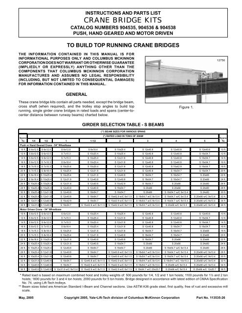
These crane bridge kits contain all parts needed, except the bridge beam,<br />
cross shaft (when required), and the trolley stop angles to build top<br />
running, single girder crane bridges in rated loads and spans (center-tocenter<br />
distance between runway beams) charted below.<br />
GIRDER SELECTION TABLE - S BEAMS<br />
Figure 1.<br />
(**) BEAM SIZES FOR VARIOUS SPANS<br />
(*) RATED LOAD IN TONS OF 2000#<br />
Spans<br />
To 1/4 1/2 1 1-1/2 2 3 4 5<br />
Push or Hand Geared Crane - 54" Wheelbase<br />
10 ft. S 6x12.5 S 6x12.5 S 6x12.5 S 8x18.4 S 10x25.4 S 12x40.8 S 12x40.8 S 12x40.8 10 ft.<br />
12 ft. S 6x12.5 S 6x12.5 S 7x15.3 S 10x25.4 S 10x25.4 S 12x40.8 S 12x40.8 S 18x54.7 12 ft.<br />
14 ft. S 6x12.5 S 6x12.5 S 7x15.3 S 10x25.4 S 12x31.8 S 12x40.8 S 12x40.8 S 18x54.7 14 ft.<br />
16 ft. S 6x12.5 S 7x15.3 S 8x18.4 S 10x25.4 S 12x31.8 S 12x40.8 S 12x40.8 S 18x54.7 16 ft.<br />
18 ft. S 7x15.3 S 7x15.3 S 10x25.4 S 10x25.4 S 12x31.8 S 12x40.8 S 15x42.9 S 18x54.7 18 ft.<br />
20 ft. S 7x15.3 S 8x18.4 S 10x25.4 S 12x31.8 S 12x31.8 S 12x40.8 S 18x54.7 S 18x54.7 20 ft.<br />
22 ft. S 8x18.4 S 10x25.4 S 10x25.4 S 12x31.8 S 12x40.8 S 18x54.7 S 18x54.7 S 20x66 22 ft.<br />
24 ft. S 8x18.4 S 10x25.4 S 12x31.8 S 12x40.8 S 12x40.8 S 18x54.7 S 18x54.7 S 20x66 24 ft.<br />
26 ft. S 10x25.4 S 10x25.4 S 12x31.8 S 12x40.8 S 15x42.9 S 18x54.7 S 20x66 S 24x80 26 ft.<br />
28 ft. S 10x25.4 S 10x25.4 S 12x40.8 S 12x40.8 S 18x54.7 S 20x66 S 20x66 S 24x80 28 ft.<br />
30 ft. S 10x25.4 S 12x31.8 S 12x40.8 S 18x54.7 S 18x54.7 S 20x66 S 18x54.7 w/C 9x13.4 S 24x80 30 ft.<br />
32 ft. S 10x25.4 S 12x31.8 S 12x40.8 S 18x54.7 S 15x42.9 w/C 8x11.5 S 18x54.7 w/C 9x13.4 S 18x54.7 w/C 9x13.4 S 20x66 w/C 9x13.4 32 ft.<br />
34 ft. S 12x31.8 S 12x40.8 S 15x42.9 S 18x54.7 S 15x42.9 w/C 8x11.5 S 18x54.7 w/C 9x13.4 S 18x54.7 w/C 9x13.4 S 20x66 w/C 9x13.4 34 ft.<br />
36 ft. S 12x31.8 S 12x40.8 S 18x54.7 S 15x42.9 w/C 8x11.5 S 15x42.9 w/C 8x11.5 S 18x54.7 w/C 9x13.4 S 20x66 w/C 9x13.4 S 20x66 w/C 9x13.4 36 ft.<br />
Motor Driven Crane - 54" Wheelbase<br />
10 ft. S 6x12.5 S 6x12.5 S 6x12.5 S 10x25.4 S 10x25.4 S 12x40.8 S 12x40.8 S 12x40.8 10 ft.<br />
12 ft. S 6x12.5 S 6x12.5 S 7x15.3 S 10x25.4 S 12x31.8 S 12x40.8 S 12x40.8 S 18x54.7 12 ft.<br />
14 ft. S 6x12.5 S 6x12.5 S 7x15.3 S 10x25.4 S 12x31.8 S 12x40.8 S 12x40.8 S 18x54.7 14 ft.<br />
16 ft. S 6x12.5 S 7x15.3 S 8x18.4 S 10x25.4 S 12x31.8 S 12x40.8 S 18x54.7 S 18x54.7 16 ft.<br />
18 ft. S 7x15.3 S 8x18.4 S 10x25.4 S 12x31.8 S 12x31.8 S 18x54.7 S 18x54.7 S 20x66 18 ft.<br />
20 ft. S 7x15.3 S 8x18.4 S 10x25.4 S 12x31.8 S 12x40.8 S 18x54.7 S 18x54.7 S 20x66 20 ft.<br />
22 ft. S 8x18.4 S 10x25.4 S 12x31.8 S 12x40.8 S 12x40.8 S 18x54.7 S 20x66 S 20x66 22 ft.<br />
24 ft. S 10x25.4 S 10x25.4 S 12x31.8 S 12x40.8 S 18x54.7 S 20x66 S 20x66 S 24x80 24 ft.<br />
26 ft. S 10x25.4 S 10x25.4 S 12x40.8 S 18x54.7 S 18x54.7 S 20x66 S 18x54.7 w/C 9x13.4 S 24x80 26 ft.<br />
28 ft. S 10x25.4 S 12x31.8 S 12x40.8 S 18x54.7 S 12x40.8 w/C 8x11.5 S 18x54.7 w/C 9x13.4 S 18x54.7 w/C 9x13.4 S 20x66 w/C 9x13.4 28 ft.<br />
30 ft. S 10x25.4 S 12x31.8 S 12x40.8 S 18x54.7 S 12x40.8 w/C 8x11.5 S 18x54.7 w/C 9x13.4 S 18x54.7 w/C 9x13.4 S 20x66 w/C 9x13.4 30 ft.<br />
32 ft. S 12x31.8 S 12x40.8 S 18x54.7 S 12x40.8 w/C 8x11.5 S 15x42.9 w/C 8x11.5 S 18x54.7 w/C 9x13.4 S 18x54.7 w/C 10x15.3 S 20x66 w/C 9x13.4 32 ft.<br />
34 ft. S 12x40.8 S 12x40.8 S 18x54.7 S 15x42.9 w/C 8x11.5 S 15x42.9 w/C 8x11.5 S 18x54.7 w/C 9x13.4 S 20x66 w/C 9x13.4 S 20x66 w/C 9x13.4 34 ft.<br />
36 ft. S 12x40.8 S 12x40.8 S 12x31.8 w/C 9x13.4 S 15x42.9 w/C 8x11.5 S 15x42.9 w/C 8x11.5 S 18x54.7 w/C 20x20.7 S 20x66 w/C 9x13.4 S 20x66 w/C 12x20.7 36 ft.<br />
* Rated load is based on maximum combined hoist and trolley weights of: 500 pounds for 1/4, 1/2 and 1 ton hoists; 1100 pounds for 1½ and 2 ton<br />
hoists; 1600 pounds for 3 and 4 ton hoists; 2000 pounds for 5 ton hoists. Bridge designed in accordance with latest edition of CMAA Specification<br />
No. 74, using Lift-Tech trolleys.<br />
** Beam sizes listed are American Standard I-Beam and Channel sections. Use ASTM A36 grade steel, first quality, free of rust and excessive mill<br />
scale.<br />
May, 2005 Copyright 2005, Yale Lift-Tech division of Columbus McKinnon Corporation Part No. <strong>113535</strong>-26<br />
12750<br />
Spans<br />
To
Spans<br />
(**) BEAM SIZES FOR VARIOUS SPANS<br />
(*) RATED LOAD IN TONS OF 2000#<br />
To 1/4 1/2 1 1-1/2 2 3 4 5<br />
Push or Hand Geared Crane - 54" Wheelbase<br />
10 ft. W 6x12 W 6x12 W 8x15 W 10x19 W 12x22 W 10x30 W 14x38 W 18x46 10 ft.<br />
12 ft. W 6x12 W 6x12 W 8x15 W 10x19 W 12x22 W 12x35 W 18x40 W 18x46 12 ft.<br />
14 ft. W 6x12 W 6x12 W 8x15 W 10x19 W 10x26 W 12x35 W 18x40 W 18x46 14 ft.<br />
16 ft. W 6x12 W 8x15 W 8x18 W 10x26 W 14x26 W 14x38 W 16x45 W 16x50 16 ft.<br />
18 ft. W 8x15 W 8x18 W 8x18 W 10x26 W 10x30 W 18x40 W 16x45 W 18x55 18 ft.<br />
20 ft. W 8x15 W 8x18 W 8x21 W 10x26 W 10x30 W 18x40 W 18x46 W 16x57 20 ft.<br />
22 ft. W 8x18 W 8x18 W 10x26 W 10x30 W 14x34 W 12x45 W 16x50 W 16x57 22 ft.<br />
24 ft. W 8x18 W 8x21 W 10x26 W 10x30 W 12x35 W 16x45 W 16x50 W 16x57 24 ft.<br />
26 ft. W 8x21 W 10x22 W 10x30 W 12x35 W 14x38 W 14x48 W 14x53 W 18x60 26 ft.<br />
28 ft. W 10x22 W 10x26 W 10x30 W 14x38 W 12x40 W 14x48 W 16x57 W 18x65 28 ft.<br />
30 ft. W 10x22 W 10x26 W 14x34 W 12x40 W 14x43 W 14x53 W 18x65 W 18x71 30 ft.<br />
32 ft. W 10x26 W 10x30 W 12x35 W 14x43 W 14x48 W 18x60 W 16x67 W 16x77 32 ft.<br />
34 ft. W 10x26 W 12x30 W 14x38 W 14x48 W 14x48 W 18x65 W 16x67 W 16x77 34 ft.<br />
36 ft. W 10x30 W 14x34 W 12x40 W 14x48 W 14x53 W 16x67 W 16x77 W 16x89 36 ft.<br />
Motor Driven Crane - Single Drive - 36" and 54" Wheelbase<br />
10 ft. W 6x12 W 6x12 W 8x15 W 10x19 W 12x22 W 12x35 W 18x40 W 18x46 10 ft.<br />
12 ft. W 6x12 W 6x12 W 8x15 W 10x19 W 10x26 W 12x35 W 18x40 W 18x46 12 ft.<br />
14 ft. W 6x12 W 6x12 W 8x18 W 10x26 W 14x26 W 14x38 W 10x45 W 16x50 14 ft.<br />
16 ft. W 6x12 W 8x15 W 8x18 W 10x26 W 10x30 W 18x40 W 16x45 W 14x53 16 ft.<br />
18 ft. W 8x15 W 8x18 W 8x21 W 10x26 W 10x30 W 18x40 W 18x46 W 16x57 18 ft.<br />
20 ft. W 8x18 W 8x18 W 8x21 W 10x30 W 10x30 W 10x45 W 12x50 W 16x57 20 ft.<br />
22 ft. W 8x18 W 8x21 W 10x26 W 10x30 W 12x35 W 16x45 W 16x50 W 16x57 22 ft.<br />
24 ft. W 8x18 W 8x21 W 10x26 W 14x34 W 14x38 W 14x48 W 14x53 W 18x65 24 ft.<br />
26 ft. W 8x21 W 10x26 W 10x30 W 12x35 W 12x40 W 12x50 W 16x57 W 18x65 26 ft.<br />
28 ft. W 10x22 W 10x26 W 10x33 W 12x40 W 12x40 W 14x53 W 18x65 W 18x71 28 ft.<br />
30 ft. W 10x26 W 10x30 W 12x35 W 12x40 W 12x45 W 14x53 W 16x67 W 14x74 30 ft.<br />
32 ft. W 10x26 W 10x30 W 14x38 W 12x45 W 14x48 W 14x61 W 16x67 W 16x77 32 ft.<br />
34 ft. W 10x30 W 14x34 W 12x40 W 14x48 W 14x53 W 16x67 W 16x67 W 16x89 34 ft.<br />
36 ft. W 10x30 W 12x35 W 12x40 W 14x53 W 14x61 W 16x67 W 16x77 W 16x89 36 ft.<br />
Motor Driven Crane - Dual Drive - 72" Wheelbase<br />
38 ft. W12x35 W12x40 W14x48 W14x61 W16x67 W16x77 W16x89 W18x97 38 ft.<br />
40 ft. W12x40 W12x45 W14x53 W16x67 W16x67 W16x89 W18x86 W21x101 40 ft.<br />
42 ft. W12x40 W14x48 W14x61 W16x67 W16x67 W18x86 W18x97 W21x101 42 ft.<br />
44 ft. W14x43 W14x48 W14x61 W16x67 W16x77 W18x86 W21x101 W21x111 44 ft.<br />
46 ft. W14x48 W14x53 W16x67 W16x77 W18x76 W18x97 W21x101 W21x111 46 ft.<br />
48 ft. W14x53 W14x61 W16x67 W18x76 W18x86 W21x101 W21x111 W21x122 48 ft.<br />
Page 2<br />
GIRDER SELECTION TABLE - WIDE FLANGE BEAMS<br />
* Rated load is based on maximum combined hoist and trolley weights of: 500 pounds for 1/4, 1/2 and 1 ton hoists; 1100 pounds for 1½ and 2 ton<br />
hoists; 1600 pounds for 3 and 4 ton hoists; 2000 pounds for 5 ton hoists. Bridge designed in accordance with latest edition of CMAA Specification<br />
No. 74, using Lift-Tech trolleys.<br />
** Beam sizes listed are American Standard Wide Flange Beam sections. Use ASTM A36 grade steel, first quality, free of rust and excessive mill<br />
scale.<br />
Catalog Number Required to Build a Push Crane Bridge<br />
For Spans<br />
Thru<br />
(ft)<br />
Rated Load<br />
Range<br />
(tons)<br />
1 Pair of<br />
End Trucks<br />
(Catalog<br />
Number)<br />
36 1/4 thru 5 904535<br />
Spans<br />
To
For<br />
Spans<br />
Thru<br />
(ft)<br />
8<br />
* Includes one Cross Shaft Support and two Cross Shaft Couplings.<br />
** 36 feet of Hand Chain.<br />
For<br />
Spans<br />
Thru<br />
(ft)<br />
8<br />
Rated<br />
Load<br />
Range<br />
(tons)<br />
Motor 115V Control<br />
208-230V 460V 575V 208-230V 460V 575V<br />
905394 905395 905396 904546 904547 904548<br />
Voltage Brake<br />
120-240/1/60<br />
230-460/1/60<br />
575/3/60<br />
Rated<br />
Load<br />
Range<br />
(tons)<br />
Catalog Numbers Required to Build a Motor Driven Single Drive Crane Bridge<br />
1 Pair of<br />
End<br />
Trucks<br />
(Catalog<br />
Number)<br />
Cross Shaft<br />
Support<br />
Number<br />
Req’d<br />
905554<br />
905555<br />
905556<br />
Catalog<br />
Number<br />
Cross Shaft<br />
Coupling<br />
Number<br />
Req’d<br />
0<br />
2<br />
15<br />
1/4<br />
1 2<br />
22 thru <strong>904536</strong> 2 904540 2<br />
29<br />
5<br />
3 3<br />
36 4 3<br />
Catalog<br />
Number<br />
10:1<br />
Ratio<br />
(101 fpm)<br />
Catalog Numbers Required for Optional Equipment<br />
Bridge Bumpers 932000<br />
Gear Reducer Motor Control Fused<br />
Disconnect<br />
15:1<br />
Ratio<br />
(67 fpm)<br />
20:1<br />
Ratio<br />
(51 fpm)<br />
208-<br />
230/<br />
460V 575V<br />
208-<br />
230V 460V 575V<br />
208-<br />
230V<br />
Switch<br />
460-<br />
575V<br />
905374 905376 905377 905378 905381 905382 904541 904542 904543 905388 905389<br />
Two Speed Motors and Controls Single Phase Motors and Controls<br />
Ballast Resistors<br />
208-230V 460V 575V<br />
905391 905392 905393<br />
Bridge Brake<br />
1 Pair of<br />
End Trucks<br />
(Cat. No. <strong>904536</strong>)<br />
Chain Wheel<br />
& Guide*<br />
(Cat. No. 904539)<br />
Catalog Number<br />
Electronic Acceleration Control<br />
(208-230-460/3/60)<br />
Single Speed<br />
Two Speed<br />
Hand Chain**<br />
(Cat No. 8282)<br />
904596<br />
904598<br />
Number<br />
Req’d<br />
Cross Shaft<br />
Support<br />
Catalog<br />
Number<br />
15 0 0<br />
22 1/4 thru 5 <strong>904538</strong><br />
1 904540 0<br />
29 2 1<br />
36 3 1<br />
Girder Connection Kits<br />
Bolted Uncoped Girder - 54" WB 912099<br />
Bolted Uncoped Girder - 72" WB 912102<br />
Coped Girder 912101<br />
Catalog Numbers Required to Build a Hand Geared Crane Bridge<br />
0<br />
Motor 115V Control<br />
120-240V 120V 240V<br />
905363 904544 904545<br />
Fused Disconnect Switch<br />
Voltage Switch<br />
208-230/3/60<br />
460-575/3/60<br />
120/1/60<br />
240/1/60<br />
Air Motor<br />
Drive Package<br />
Number<br />
Req’d<br />
0<br />
Cross Shaft<br />
Coupling<br />
Catalog<br />
Number<br />
905374<br />
905338<br />
905389<br />
905366<br />
905367<br />
904558<br />
Page 3
Max.<br />
Capacity<br />
(tons)<br />
5<br />
Max.<br />
Span<br />
(ft)<br />
36<br />
48<br />
Max.<br />
Span<br />
(ft)<br />
36<br />
48<br />
Page 4<br />
Max.<br />
Span<br />
(ft)<br />
36<br />
48<br />
Catalog Numbers Required to Build a Motor Driven Dual Drive Crane Bridge<br />
Travel<br />
Speed<br />
(fpm)<br />
50, 70<br />
and 100<br />
Travel<br />
Speed<br />
(fpm)<br />
50, 70<br />
and 100<br />
No.<br />
of<br />
Speeds<br />
Single<br />
Two<br />
Motor<br />
2 Req’d<br />
1/2 hp<br />
905381<br />
1/2 hp<br />
905395<br />
460 Volt Power 575 Volt Power<br />
Control<br />
1 Req’d<br />
Disconnect<br />
Switch<br />
1 Req’d<br />
44600383 905389<br />
44600393 905389<br />
Motor<br />
2 Req’d<br />
1/2 hp<br />
905382<br />
1/2 hp<br />
905396<br />
Control<br />
1 Req’d<br />
50 – Not Available Not Available<br />
70<br />
100<br />
No.<br />
of<br />
Speeds<br />
Single<br />
Two<br />
Single<br />
Two<br />
Single<br />
Two<br />
Motor<br />
2 Req’d<br />
1/2 hp<br />
905381<br />
1/2 hp<br />
32879624<br />
1/2 hp<br />
905381<br />
1/2 hp<br />
905395<br />
3/4 hp<br />
32879542<br />
3/4 hp<br />
32879636<br />
200 - 208 Volt Power 230 Volt Power<br />
Control<br />
1 Req’d<br />
Disconnect<br />
Switch<br />
1 Req’d<br />
44600326 905388<br />
44600336 905388<br />
44600383 905389<br />
44600393 905389<br />
44600327 905389<br />
44600337 905389<br />
Motor<br />
2 Req’d<br />
1/2 hp<br />
905381<br />
1/2 hp<br />
905394<br />
1/2 hp<br />
905382<br />
1/2 hp<br />
905396<br />
3/4 hp<br />
32879543<br />
3/4 hp<br />
32879637<br />
Control<br />
1 Req’d<br />
50 – Not Available Not Available<br />
70<br />
100<br />
Speed<br />
(fpm)<br />
Single<br />
Two<br />
Single<br />
Two<br />
Rail<br />
Size<br />
(# / yd)<br />
Kit Code<br />
Number<br />
1/2 hp<br />
905381<br />
1/2 hp<br />
32879624<br />
3/4 hp<br />
32879542<br />
3/4 hp<br />
32879643<br />
End Truck<br />
Code Number<br />
Kit Consists of<br />
44600326 905388<br />
44600336 905388<br />
44600329 905388<br />
44600339 905388<br />
Gear Reducer<br />
(Qty. 2)<br />
50<br />
B05/36TD*50<br />
905378<br />
<strong>904536</strong><br />
70 25 to 40 B05/36TD*70 905377<br />
4’ - 6" WB<br />
100 B05/36TD*100 905376<br />
50<br />
70 40 B05/48TD*70 904549<br />
100 B05/48TD*100 6’ - 0" WB 905376<br />
* Insert 1 for Single Speed or 2 for Two Speed<br />
905377<br />
Not Available<br />
1/2 hp<br />
905381<br />
1/2 hp<br />
905394<br />
3/4 hp<br />
32879542<br />
3/4 hp<br />
32879635<br />
Approximate Shipping<br />
Weight (lbs)<br />
Controls<br />
&<br />
Motor 1 Speed 2 Speed<br />
1 each Control<br />
2 each 1/2 hp Motor<br />
1 each Disconnect<br />
(See Below)<br />
1 each Control<br />
2 each 3/4 hp Motor<br />
1 each Disconnect<br />
(See Below)<br />
Motors and Controls - Motor Driven - Dual Drive Top Running Cranes<br />
575 615<br />
675 715<br />
Disconnect<br />
Switch<br />
1 Req’d<br />
44600326 905388<br />
44600336 905388<br />
44600326 905388<br />
44600336 905388<br />
44600329 905388<br />
44600339 905388<br />
Disconnect<br />
Switch<br />
1 Req’d<br />
44600384 905389<br />
44600394 905389<br />
44600384 905389<br />
44600394 905389<br />
44600328 905389<br />
44600338 905389
The proper catalog numbers must be ordered to build the crane<br />
required. For a push crane only one catalog number is required.<br />
Three are required for a hand geared crane, seven are required<br />
for a single motor driven crane and five are required for a dual<br />
drive motor driven crane. Options are also available. Catalog<br />
numbers are shown on pages 2 and 3.<br />
End trucks have 8" diameter wheels. Minimum recommended<br />
runway rail is ASCE 20#. Maximum size runway rail for minimum<br />
CMAA Specification No. 74 float of 3/4" is ASCE 45#. Maximum<br />
permissible rail size is ASCE 60# with a reduced float of 3/8".<br />
Width between wheel flanges is 2-3/4".<br />
NOTICE<br />
When installing crane on existing runways, make sure rails<br />
are straight and parallel within tolerances shown below.<br />
Reposition rail if necessary.<br />
Runway beams must be properly designed to support bridge,<br />
hoist, trolley and rated load. Runway rails must be level and<br />
parallel within ± 1/8". Maximum slope of runway must not be more<br />
than 1/16" in 1 foot. Rail separation at joints should not exceed<br />
1/32". Runway stops must be positioned to contact both ends of<br />
the crane simultaneously.<br />
Maximum allowable wheel load determined in accordance with<br />
CMAA Specification No. 74 is 6500 pounds. Weight of one 54"<br />
wheelbase end truck is 225 pounds and of one 72" wheelbase<br />
truck is 300 lbs.<br />
MATERIAL TO BE PURCHASED LOCALLY<br />
TO COMPLETE A CRANE BRIDGE<br />
1. Bridge Beam. Obtain one length of American Standard<br />
I-Beam Section at the size recommended (see chart on page 1)<br />
or American Standard Wide Flange Beam Section at the size<br />
recommended (see chart on page 2) for the required capacity<br />
and span of bridge. The beam selected should be reviewed by a<br />
structural engineer for the application. The beam that you order<br />
must be a minimum length of the span plus 9-1/4". The beam<br />
selected must be straight with flanges parallel to each other and<br />
flanges at 90 degrees to the web. See Figure 2. For long spans<br />
with the larger rated loads, a channel is also required. The<br />
channel must be a minimum length of the span minus 4'-0".<br />
11953<br />
Figure 2. Correct Beam Selection.<br />
2. Trolley Stops. Four (4) angles must be cut to size and installed<br />
at the ends of the bridge girder per Figure 7.<br />
WARNING<br />
Trolley stops (clip angles) must be installed on both<br />
ends of bridge beam (see Figure 7) to prevent hoist<br />
trolley from running off end of beam, which could result<br />
in injury to operator and others and damage to load and<br />
other property.<br />
3. Cross Shaft. For hand geared and motor driven single drive<br />
cranes, cross shafts are also required. The cross shafts are to be<br />
1" diameter AISI 1018 cold drawn steel with a standard mill<br />
tolerance of + .000", - .002". For spans thru 22'-0", only one length<br />
of cross shaft is required and the length required is the span<br />
minus 2'-2-1/2". For spans over 22'-0", two lengths of cross shaft<br />
are required. One length is to be 14'-9" and the other is to be the<br />
span minus 16'-11-5/8". Shaft lengths may be equalized if care is<br />
taken to clear supports.<br />
NOTICE<br />
A. All of the tables used in selection of structural steel<br />
beams have been produced by our engineering department<br />
using well established design guides for this type of crane<br />
bridge. IT IS IMPORTANT THAT ALL INSTRUCTIONS BE<br />
FOLLOWED AND THAT RECOMMENDED COMPONENT<br />
APPLICATION LIMITS NOT BE EXCEEDED.<br />
B. Assembly of beam and channel requires welding. IT IS<br />
EXTREMELY IMPORTANT TO THE SAFETY OF THIS<br />
BRIDGE THAT THIS WELDING BE DONE BY A COMPE-<br />
TENT WELL TRAINED WELDER. It is our strong recommendation<br />
that the welder used in this construction be qualified<br />
as prescribed by the American Welding Society (AWS)<br />
Specification for Welding Industrial and Mill Cranes D14.1<br />
- latest issue.<br />
FABRICATION OF GIRDER FOR BRIDGE<br />
BEAM WITH CAPPING CHANNEL<br />
Refer to Figure 3. Place channel on supports as shown in Step I.<br />
The I-beam is sighted for camber and placed with camber in<br />
direction shown in Step II. Weld one end of channel to the I-beam.<br />
Clamp, with “C” clamps, the channel to the I-beam flange -<br />
provide sufficient “C” clamps so as to hold channel in contact with<br />
the I-beam. Weld in accordance with the weld information given,<br />
starting at one end, staggering weld from side-to-side, proceeding<br />
to the opposite end without interruption. It is important to<br />
stagger weld from side-to-side in order to retain beam straitness.<br />
After welding, draw a taut string from end to end of beam as<br />
shown. Beam should either be parallel to string or have some<br />
camber. Camber should not exceed 1/800 of span.<br />
Page 5
12725A<br />
12739<br />
Page 6<br />
Figure 3.<br />
Figure 4. Cutting Diagram.
NOTCHING OF BRIDGE BEAM<br />
TO FIT END TRUCKS<br />
Note the bridge beam end connections shown in Figure 6. If<br />
adequate headroom is available above the truck, there is an<br />
optional end connection shown for push cranes for 6", 7" and 8"<br />
beams only that does not require notching of the beam.<br />
If notching is required, set beam on supports as shown in Step 1<br />
of Figure 3. If a channel has been welded to the beam, the beam<br />
is already in the proper position. Cut notches in both ends of the<br />
beam using cutting diagram of Figure 4 and the proper dimensions<br />
for the required beam size. Notch is made by cutting torch<br />
with the burned area smoothed by grinding.<br />
INSTRUCTIONS FOR ASSEMBLING<br />
PUSH BRIDGE WITH COPED GIRDER<br />
1. Turn beam over on supports with camber side up. When setting<br />
up beam on supports, make certain that the bottom flange is level<br />
as shown in Figure 5. The larger wheel flange goes inside the<br />
span.<br />
2. Position long angles from kit as shown in Figure 6 and securely<br />
clamp into place.<br />
3. Set up, square, block and securely clamp trucks into position<br />
as shown in Figure 6. Make certain trucks are level with each<br />
other and are level with bottom flange of bridge beam as shown<br />
in Figure 5 (it is possible that top flange of beam may not be level<br />
even though bottom flange is). When leveling trucks, use either<br />
the centerline of the wheel axles or the diameter of the wheels.<br />
DO NOT LEVEL FROM TRUCK STRUCTURE. Correct operation<br />
of hoist-trolley unit requires that the bottom flange be level.<br />
4. For beams over 7" deep; when leveling the bottom flange of the<br />
12740<br />
Figure 5. Method of Setting End Truck to Girder.<br />
bridge beam, clamp the short angle in position shown in Figure<br />
6 to secure the position of the beam. Discard short angles for 6"<br />
and 7" beams.<br />
5. Square end truck to end of bridge beam at one end of beam.<br />
Make sure trucks are parallel by measuring outside of wheel<br />
flanges across span at both ends of truck with end play for all<br />
wheels taken up in one direction.<br />
6. Check center to center of trucks. This may be done by<br />
measuring from the inside edge of the truck at one end of the<br />
bridge to the outside corresponding edge of the truck at the other<br />
end of the bridge. This should equal the span length.<br />
7. When all dimensions are confirmed, bottom flange of bridge<br />
beam is parallel to wheels of truck and truck is securely clamped<br />
to bridge beam, weld the two long angles at each end of the<br />
bridge beam to the web as shown in Figure 6.<br />
8. Drill 4 holes 41/64" diameter thru truck flanges using holes in<br />
angles as a template at both ends of bridge.<br />
9. For beams over 7" deep, weld the short angle at each end of<br />
the bridge beam to the web as shown in Figure 6.<br />
10. Drill 2 holes 41/64" diameter thru bridge beam web using<br />
holes in angle as a template in locations shown in Figure 6, at<br />
both ends of bridge.<br />
11. Assemble long angles to truck flange using eight (four at each<br />
end of bridge) 5/8" diameter bolts furnished with kit. Put one flat<br />
washer under bolt head and one under the self-locking nut.<br />
Tighten all bolts and nuts using the turn-of-nut method. This is<br />
done by alternately bringing bolts and nuts to a “snug-tight”<br />
condition to ensure that mating surfaces are brought into full<br />
contact with each other. Then, make a final 1/2 turn on all bolts<br />
and nuts.<br />
Page 7
12741A<br />
12741B<br />
Page 8<br />
6" AND 7" BEAMS<br />
8" BEAMS
12741C<br />
12741D<br />
10" BEAMS<br />
12" BEAMS<br />
Page 9
12741E<br />
12741F<br />
Page 10<br />
15", 18" & 20" BEAMS<br />
OPTIONAL END CONNECTION<br />
FOR 6", 7" & 8" BEAMS<br />
(OPTIONAL END CONNECTION FOR PUSH CRANES ONLY. DO NOT USE FOR GEARED MODELS)<br />
Figure 6. Bridge Beam End Connections.<br />
All weld is to be AWS Class E-70XX or equivalent.
Page 11<br />
UNCOPED GIRDER END CONNECTION<br />
Weld Size 'A' - Girder Flange Thickness Minus 1/16" But not greater than 5/16"<br />
Weld Size 'B' - Girder Web Thickness Minus 1/16" But not greater than 5/16"<br />
Figure 6a. Bridge Beam End Connections.<br />
All weld is to be AWS Class E-70XX or equivalent.
Page 12<br />
12742A
Page 13<br />
*Trolley frame or bumpers should contact trolley stops. If not, cut out<br />
standing leg (OSL) back to dimension shown.<br />
Size of<br />
Bridge Beam A<br />
Trolley Stop<br />
Angle Size*<br />
(4 Req’d.) B C D OSL<br />
6" x 12.5 2" 3 x 3 x 3/8 1" 2" 4" 1-1/2"<br />
7" x 15.3 2-1/4" 3 x 3 x 3/8 1" 3" 5" 1-5/8"<br />
8" x 18.4 2-1/4" 3 x 3 x 3/8 1" 3" 5" 1-3/4"<br />
10" x 25.4 2-3/4" 3-1/2 x 3 x 3/8 1-1/4" 3" 5" 2-1/8"<br />
12" x 31.8 3" 3-1/2 x 3 x 3/8 1-1/4" 3" 5" 2-1/4"<br />
15" x 42.9 3-1/2" 4 x 3 x 3/8 1-1/2" 3" 5" 2-1/2"<br />
18" x 54.7 3-1/2" 4 x 3 x 3/8 1-1/2" 3" 5" 2-3/4"<br />
20" x 66 3-1/2" 5 x 3 x 3/8 1-3/4" 3" 5" 2-3/4"<br />
Figure 7.<br />
12742
Page 14<br />
TYPICAL REQUIRED UNCOPED GIRDER END BRACING<br />
PROVIDED AND INSTALLED BY CRANE BUILDER<br />
Figure 7a.
CAUTION<br />
Do not substitute standard bolts and nuts for the special<br />
truck connecting bolts and nuts furnished with kit. Only<br />
high-strength bolts (S.A.E., grade 5) and elastic collared<br />
self-locking nuts, as furnished, are acceptable for attaching<br />
truck frames to bridge beam. High strength bolts are identified<br />
on the top of the head by three radial lines, equally spaced<br />
at 120 degrees. Self-locking nuts must have two threads,<br />
minimum extending thru nut. If necessary, discard flat<br />
washer to get two threads.<br />
12. For bridge beams over 7", bolt short angle welded at truck to<br />
bridge beam web with four (two at each end of bridge) 5/8"<br />
diameter bolts furnished with kit. Tighten using turn-of-nut method.<br />
13. Optional End Connection for 6", 7" and 8" Beams Only.<br />
a. Drill 4 holes 41/64" diameter thru bridge beam lower flange and<br />
truck flanges in locations shown in Figure 6 at both ends of<br />
bridge.<br />
b. Assemble beam to truck using eight (four at each end of bridge)<br />
5/8" diameter bolts furnished with kit. Put beveled washer under<br />
bolt head and against I-beam flange. Use self-locking nut (no flat<br />
washer) and tighten using turn-of-nut method.<br />
14. Mount trolley stops to I-beam web in position shown in Figure<br />
7. Stops may be welded or bolted in place. If bolted, drill holes<br />
using 21/32" diameter drill as indicated in Figure 7. 5/8" diameter<br />
bolts with self-locking nuts should be used to secure stops.<br />
15. If it is desired to increase the rigidity of the bridge, four angles<br />
(one to each corner) may be added in the position shown as<br />
“Optional” (at 45° to the bridge I-beam) in Figure 7. On a motor<br />
driven crane it may be necessary to move the electrical enclosure<br />
for clearance reasons.<br />
INSTRUCTIONS FOR ASSEMBLING<br />
PUSH BRIDGE WITH UNCOPED GIRDER<br />
1. Turn Beam over on supports with camber side up. When<br />
setting up beam on supports, make certain that the bottom flange<br />
is level as shown in Figure 5. The larger wheel flange goes inside<br />
the span.<br />
2. Position girder mounting plates on top of each truck center<br />
plate and clamp securely. Drill 4 holes 41/64" diameter through<br />
truck center plate and flanges of truck channels using holes in<br />
girder mounting plate as template.<br />
3. Assemble girder mounting plate to top plate of each truck using<br />
eight (four at each end of bridge) 5/8" diameter high strength<br />
grade 5 bolts furnished with end connection kit. Put one flat<br />
washer under bolt head and one under the self locking nut.<br />
Tighten all bolts and nuts using the turn-of-nut method. This is<br />
done by alternately bringing bolts and nuts to a "snug-tight"<br />
condition to ensure that mating surfaces are brought into full<br />
contact with each other. Then, make a final ½ turn on all bolts and<br />
nuts.<br />
4. Set up, square, block and securely clamp trucks into position<br />
as shown in Figure 6. Make certain trucks are level with each<br />
other and are level with bottom flange of bridge beam as shown<br />
in Figure 5 (it is possible that top flange of beam may not be level<br />
even though bottom flange is). When leveling trucks use either<br />
the centerline of the wheel axles or the diameter of the wheels.<br />
DO NOT LEVEL FROM TRUCK STRUCTURE. Correct operation<br />
of hoist-trolley requires that the bottom flange be level.<br />
5. Square end truck to end of bridge beam at one end of beam.<br />
Make sure trucks are parallel by measuring outside of wheel<br />
flanges across span at both ends of truck with end play for all<br />
wheels taken up in one direction.<br />
6. Check center to center of trucks. This may be done by<br />
measuring from the inside edge of the truck at one end of the<br />
bridge to the outside corresponding edge of the truck at the other<br />
end of the bridge. This should equal the span length.<br />
7. When all dimensions are confirmed, bottom flange of bridge<br />
beam is parallel to wheels of truck and truck is securely clamped<br />
to bridge beam, weld the girder bottom flange to the girder<br />
mounting plate as shown in Figure 6.<br />
8. Cut 3/8" girder end cap plate and weld to end of girder and<br />
girder mounting plate as shown in Figure 6.<br />
9. To provide rigidity to the bridge, four braces (one to each<br />
corner and one to girder web parallel to truck) may shall be added<br />
in the position shown in Figure 7a. On an motor driven crane it<br />
may be necessary to move the electrical enclosure for clearance.<br />
10. Mount trolley stops to beam girder web in position shown in<br />
Figure 7. Stops may be welded or bolted in place. If bolted, drill<br />
holes using 21/32" diameter drill as indicated in Figure 7. 5/8"<br />
diameter bolts with self-locking nuts should be used to secure<br />
stops. Stop material by customer.<br />
INSTRUCTIONS FOR ASSEMBLING<br />
HAND GEARED CRANE BRIDGE<br />
1. Follow instructions for assembling the appropriate push crane<br />
bridge.<br />
2. Locate and drill holes for cross shaft supports.<br />
3. Bolt the cross shaft support angles to the bridge beam. The flat<br />
washer goes under the bolt head and the beveled washer goes<br />
between the beam flange and the lockwasher and nut.<br />
4. Attach a flange bearing to each cross shaft support plate with<br />
two carriage bolts, lockwashers and hex nuts. The carriage bolt<br />
head locks in the bearing (see Figure 13).<br />
5. Place the proper number of bearings and couplings on the<br />
cross shaft, set the unit in place and clamp the cross shaft support<br />
plates to the cross shaft support angles. The hand chain wheel<br />
and chain guide must also be placed on the cross shaft before<br />
placing. They may be positioned anywhere across the span, but<br />
must be within 12" of a cross shaft support or truck.<br />
6. Check horizontal alignment of the cross shaft by using a taut<br />
line. Weld plates to angles when alignment is complete. Weld as<br />
shown in Section A-A of Figure 7.<br />
7. Check the space between ends of cross shafts; it should be<br />
1/8". Position the couplings and drill 1/4" diameter holes through<br />
the shaft and coupling using the holes in one side of the coupling<br />
as a guide. Shaft and coupling is secured by socket head cap<br />
screws with flat washers and self-locking hex nuts (see Figure<br />
14). Tighten set screws in flange bearings.<br />
8. Set position of hand chain wheel and chain guide (within 12"<br />
of cross shaft bracket or truck) with set screw on hand chain<br />
wheel. Determine length of operating hand chain (chain should<br />
hang about 2 feet 6 inches above floor), cut chain and make it<br />
endless by installing and closing open link furnished with chain.<br />
Page 15
Page 16<br />
INSTRUCTIONS FOR ASSEMBLING<br />
MOTOR DRIVEN SINGLE DRIVE<br />
CRANE BRIDGE<br />
1. Follow instructions for assembling push crane bridge.<br />
2. Locate and drill holes for cross shaft supports.<br />
3. Bolt the cross shaft support angles to the bridge beam. The flat<br />
washer goes under the bolt head and the beveled washer goes<br />
between the beam flange and the lockwasher and nut.<br />
4. Bolt the motor to the gear reducer with four hex head bolts and<br />
lockwashers and bolt the support plate to the gear reducer with<br />
two hex socket head cap screws and lockwashers. The drive may<br />
go on either end of the bridge. Optional motor-gear reducer<br />
locations are shown in Figure 8. The vent (Ref. No. 15 in Figure<br />
16) must be placed in the highest location.<br />
5. Place key in truck drive shaft, slide gear reducer into place over<br />
shaft and bolt support plate to side of truck with two hex socket<br />
head cap screws and lockwashers. Maximum allowable torque is<br />
10 pound feet. Tighten six set screws in gear reducer hollow shaft<br />
(Ref. No. 18 in Figure 16).<br />
6. Using the 9/32" diameter hole in the support plate as a guide,<br />
drill a 5/16" diameter hole through the support plate and truck<br />
side and drive the groove pin, furnished, into the hole (Ref. No.<br />
4 in Figure 16).<br />
7. Attach a flange bearing to each cross shaft support plate with<br />
two carriage bolts, lockwashers and hex nuts. The carriage bolt<br />
head locks in the bearing (see Figure 13).<br />
8. Place the proper number of bearings and couplings on the<br />
cross shaft, set the unit in place and clamp the cross shaft support<br />
plates to the cross shaft support angles.<br />
9. Check horizontal alignment of the cross shaft by using a taut<br />
line. Weld plates to angles when alignment is complete. Weld as<br />
shown in Section A-A of Figure 7.<br />
10. Check the space between cross shafts; it should be 1/8".<br />
Position the couplings and drill 1/4" diameter holes through the<br />
shaft and coupling using the holes in one side of the coupling as<br />
a guide. Shaft and coupling is secured by socket head cap<br />
screws with flat washers and self-locking hex nuts (see Figure<br />
14). Tighten set screws in flange bearings.<br />
11. The electrical enclosure is shown mounted on the inside of<br />
the truck over the gear reducer in Figure 17. The connecting<br />
bracket may be mounted in any of 3 vertical locations on the<br />
enclosure bracket when oriented as shown. It may also be<br />
rotated 180° (out standing leg at top) giving 3 additional positions.<br />
The enclosure bracket may also be adjusted horizontally on the<br />
enclosure. The connecting bracket may be welded to a truck or<br />
to the girder. If the bracket rests on the supporting member, a 1"<br />
minimum overlap is required. Weld as shown in Figure 9. If the<br />
bracket is to be supported by weld at the toe only, a stiffener plate<br />
must be furnished by the crane fabricator. Weld as shown in the<br />
alternate view in Figure 9.<br />
12. Mount fused disconnect switch in any safe, convenient<br />
location.<br />
INSTRUCTIONS FOR ASSEMBLING<br />
MOTOR DRIVEN DUAL DRIVE<br />
CRANE BRIDGE<br />
1. Follow instructions for assembling push crane bridge.<br />
2. Bolt the motors to the gear reducers with four hex head bolts<br />
and lockwashers orienting the motor junction boxes appropriately<br />
after selecting the motor-gear reducer location from the options<br />
illustrated in Figure 8. Bolt the support plate to the gear reducer<br />
with two hex socket head cap screws and lockwashers. The<br />
highest oil plug in the gear reducer must be removed and the vent<br />
be installed. The hardware, vent and support plate are provided<br />
with the gear reducer.<br />
3. Place the key in the truck drive shaft and slide the gear reducer<br />
hollow shaft onto the drive shaft over the key. Bolt the support<br />
plate to the side of the truck with two hex socket head cap screws<br />
and lockwashers. Maximum allowable bolt torque is 10 pound<br />
feet.<br />
4. Repeat instruction 3 at the opposite end truck.<br />
5. The electrical enclosure is shown mounted on the inside of the<br />
truck over the gear reducer in Figure 17. The connecting bracket<br />
may be mounted in any of 3 vertical locations on the enclosure<br />
bracket when oriented as shown. It may also be rotated 180°<br />
(outstanding leg at top) giving 3 additional positions. The enclosure<br />
bracket may also be adjusted horizontally on the enclosure. The<br />
connecting bracket may be welded to a truck or to the girder. If the<br />
bracket rests on the supporting member, a 1" minimum overlap<br />
is required. Weld as shown in Figure 9. If the bracket is to be<br />
supported by weld at the toe only, a stiffener plate must be<br />
furnished by the crane bridge fabricator. Weld as shown in the<br />
alternate view in Figure 9.<br />
6. Mount fused disconnect switch in any safe convenient location.<br />
PAINTING<br />
After assembly, all plain steel surfaces should be painted.<br />
Thoroughly clean surfaces of oily spots and rust using a suitable<br />
solvent. It is recommended that a national brand zinc-chromate<br />
primer be applied before a finish coat of high gloss enamel<br />
especially suited for steel surfaces.<br />
MARKING<br />
Codes require that the capacity of the bridge be shown on both<br />
sides of crane bridge, legible from the floor. Normal practice for<br />
marking is to use capacity in tons, for example: 1 TON, 2 TON,<br />
etc. Stencil forms are readily available that may be used with<br />
brush-on or pressurized spray-can paint.<br />
NOTICE<br />
The crane builder and user are responsible for marking crane and<br />
also to check for compliance with all local, state and national<br />
codes.
12743<br />
12749<br />
Figure 8.<br />
Figure 9.<br />
Page 17
Be certain that electrical power supply to runway current<br />
conductors (if used) is “off” and locked in the open<br />
position.<br />
Page 18<br />
INSTALLATION OF CRANE BRIDGE<br />
WARNING<br />
1. Assure lifting equipment is adequate to lift total weight of crane.<br />
2. Carefully set crane bridge onto runway. Check to see that<br />
runway stops have been installed and that they engage the ends<br />
of the end trucks simultaneously.<br />
WARNING<br />
Runway stops must be installed to prevent crane bridge<br />
from running off the end of the runway rail resulting in<br />
injury to the operator and others and damages to load<br />
and other property.<br />
3. After crane is placed on runway rail, check wheel flange<br />
clearances to rail. Clearance between side of rail head and inside<br />
flange of wheel will vary from 1-3/8" for an ASCE 20# runway rail<br />
(minimum recommended rail size) to 3/8" for an ASCE 60#<br />
runway rail (maximum recommended rail size).<br />
4. When applicable follow National, State and Local electrical<br />
codes when providing electrical service to crane bridge. Make<br />
electrical connections according to the wiring diagrams furnished<br />
with the crane bridge.<br />
CAUTION<br />
Power supply must be same voltage, phase and frequency<br />
as specified on crane bridge motor nameplate.<br />
CAUTION<br />
Do not attempt to operate crane bridge before completing<br />
tests and adjustments.<br />
WARNING<br />
This equipment must be effectively grounded according<br />
to the National Electrical Code, or other applicable<br />
codes. Certain environments may prevent proper<br />
grounding by this means and in this case a separate<br />
grounding conductor should be provided.<br />
FUSE AND MAINLINE DISCONNECT PANELS<br />
Mainline disconnect panels and fused bridge control panels are<br />
provided as options to assist users in complying with OSHA and<br />
NEC codes. When ordered with crane bridge kits, they will be<br />
completely installed inside of electrical enclosures.<br />
Electrical service shall be connected to crane equipped with fuse<br />
panels and mainline disconnect panels as shown in wiring<br />
diagram.<br />
OPERATING PRECAUTIONS<br />
DO NOT load bridge beyond rated capacity.<br />
DO NOT subject bridge to side loads. Always center trolley over<br />
load when hoisting.<br />
DO NOT stand on and DO NOT cause or allow others to stand on<br />
or get under any load the bridge is supporting. DO keep clear, and<br />
make sure others keep clear, of any load the bridge is supporting.<br />
DO NOT ram bridge into runway stops, another bridge, or any<br />
obstruction on runway rails. Improper and careless operation can<br />
result in a hazardous condition for operator and load.<br />
ALWAYS be sure load is clear of obstruction before traversing<br />
load.<br />
WARNING<br />
These crane bridges are not designed nor intended to<br />
be used for support or transport of people or for<br />
transporting loads over people.<br />
If crane bridge is mounted on an open-end runway rail,<br />
then runway stops must be installed to prevent crane<br />
bridge from running off the end of the runway rail<br />
resulting in injury to the operator and others and<br />
damages to load and other property.<br />
Refer to hoist and trolley instruction manuals for safety<br />
warnings on hoists and trolleys.<br />
Read and comply with ANSI B30.16 Overhead Hoists<br />
(Underhung) and ANSI B30.17 Overhead and Gantry<br />
Cranes (Top running bridge, Single Girder, Underhung<br />
Hoist), latest editions.
MAINTENANCE AND LUBRICATION<br />
1. Inspect the bridge on a regular maintenance schedule. Check<br />
to make sure wheel axle bolts and all connections are tight.<br />
Check wheel tread surfaces for wear or damage. Check truck<br />
sides for any evidence of overload or damage. Replace any worn<br />
or damaged parts using only factory approved replacement<br />
parts.<br />
2. Lubrication requirements:<br />
a. Wheel bearings are permanently lubricated and require no<br />
additional lubricant.<br />
b. Drive wheel gears are to be lubricated with an open type gear<br />
grease which is heavy, plastic, extreme pressure and tacky; such<br />
as MOBILTAC 275 or equal.<br />
c. The hollow shaft worm gear reducer lubricant should be<br />
changed every year or 2000 hours of service for moderate usage.<br />
The lubricant should be changed more frequently if the service is<br />
more severe. Use one pint of AGMA lubricant number 7,<br />
compounded, if the ambient temperature is 15° to 60° F or AGMA<br />
lubricant number 8, compounded, if the ambient temperature is<br />
50° to 125° F.<br />
d. It is recommended that the areas of the cross shaft covered by<br />
gear reducers, bearings and couplings be coated with FEL-PRO<br />
C5-A, or equal, anti-seize lubricant.<br />
Before crane operation the gear reducer(s) vent plug must be in<br />
the proper location in the gear reducer. The vent plug replaces<br />
the pipe plug in the highest location on the end of the gear reducer<br />
(see Figure 16).<br />
3. If it becomes necessary to remove the cross shaft (Ref. No. 22<br />
in Figure 12) from the geared truck, proceed as follows:<br />
a. Remove gear reducer support plate screws (Ref. No. 3 in<br />
Figure 16).<br />
b. Loosen hollow shaft screws (Ref. No. 18 in Figure 16) and slide<br />
gear reducer off cross shaft.<br />
c. Loosen set screw in outer flange bearing (Ref. No. 19 in Figure<br />
12) (mounted on truck channel).<br />
d. Remove bolts (Ref. Nos. 18, 20 and 21 in Figure 12) holding<br />
inner flange bearing (mounted on vertical plate on truck).<br />
e. Remove outer (nearest truck center) pinion retaining ring (Ref.<br />
No. 16 in Figure 12).<br />
f. Slide cross shaft out of outer flange bearing (sliding toward<br />
center of crane) and remove retaining ring (Ref. No. 15 in Figure<br />
12) by sliding ring over end of cross shaft.<br />
g. Slide cross shaft out of pinion (Ref. No. 17 in Figure 12) and out<br />
of truck.<br />
h. Clean and inspect all parts before reassembly. Replace all<br />
parts that are worn or damaged.<br />
i. Reassemble following a reverse procedure of the disassembly<br />
steps listed above.<br />
j. Lubricate drive wheel gears per paragraph 2.b. above.<br />
4. After 3 months of initial crane operation, re-torque beam to<br />
truck bolts as called for in the assembly instructions and tighten<br />
all other bolts.<br />
REPLACEMENT PARTS<br />
The following parts list and illustrations cover standard model<br />
crane bridges. Typical units are used as the basis for the<br />
exploded parts illustrations; therefore, certain variations may<br />
occur from the parts information given. For this reason always<br />
give the catalog number, model number, motor horsepower,<br />
voltage, phase and frequency when ordering replacement parts.<br />
For motors, gearboxes, and electrical components, give complete<br />
nameplate data.<br />
The factory recommends complete replacement of the motor or<br />
gearbox.<br />
The numbers assigned to the parts of our various<br />
assemblies in our parts list are not the part numbers<br />
used in manufacturing the part. They are identification<br />
numbers, that when given with the catalog number,<br />
permit us to identify, select or manufacture and ship the<br />
correct part needed.<br />
Page 19
Page 20<br />
INDEX OF PARTS ILLUSTRATIONS<br />
Figure<br />
Title No.<br />
Push Truck - Catalog Number 904535 ......................................................................................................................... 11<br />
Geared Truck - Catalog Number <strong>904536</strong> ..................................................................................................................... 12<br />
Cross Shaft Support - Catalog Number 904540 .......................................................................................................... 13<br />
Coupling - Catalog Number 905374 ............................................................................................................................. 14<br />
Hand Chain Drive - Catalog Numbers 904539 and 8282 ............................................................................................ 15<br />
Gear Reducer (Catalog Numbers 905376 thru 905378) and Motor<br />
(Catalog Numbers 905381 and 905382) .................................................................................................................. 16<br />
Bolted Uncoped Girder Connection ............................................................................................................................. 17<br />
Electrical Enclosure and Mounting - Catalog Numbers 904541 thru 904543 ............................................................. 18<br />
Figure 11. Push Truck. Catalog Number 904535. (Only 1 Truck Shown)<br />
(Bumper is Optional. Catalog Number 932000.)<br />
12744
Figure 11. Push Truck. Catalog Number 904535. (Continued).<br />
(Bumper is Optional. Catalog Number 932000.)<br />
Ref. Part Qty.<br />
No. Number Description Req’d<br />
1 BTK-2000 Hex Head Bolt - High Strength 2<br />
2 BTK-2001 Self-Locking Nut 2<br />
3 BTK-2002 Axle 2<br />
4 BTK-2003 Bearing Retainer (Long) 2<br />
5 BTK-2004 Bearing 4<br />
6 BTK-2005 Wheel 2<br />
7 BTK-2006 Truck Weldment 1<br />
Optional Coped Girder Connection Kit - Catalog Number 912101<br />
Consists of Ref. Nos. 8 thru 12<br />
8 BTK-2007 Angle Connector 2<br />
9 BTK-2008 Hex Head Bolt - High Strength 6<br />
10 BTK-2009 Flat Washer 12<br />
11 BTK-2010 Self-Locking Nut 6<br />
12 BTK-2011 Angle Connector 1<br />
Optional Bumper - Catalog Number 904537 Consists of Ref. Nos. 14 thru 17<br />
14 BTK-2013 Hex Head Bolt 4<br />
15 BTK-2014 Flat Washer 4<br />
16 BTK-2015 Bumper 2<br />
1 7 BTK-2016 Self-Locking Nut 4<br />
18 BTK-2017 Bearing Retainer (Short) 2<br />
NOTES<br />
Page 21
Page 22<br />
Figure 12. Geared Truck. Catalog Number <strong>904536</strong>. (Only 1 Truck Shown)<br />
(Bumper is Optional. Catalog Number 932000.)<br />
Ref. Part Qty.<br />
No. Number Description Req’d<br />
1 BTK-2100 Hex Head Bolt - High Strength 2<br />
2 BTK-2101 Self-Locking Nut 2<br />
3 BTK-2102 Axle 2<br />
4 BTK-2103 Bearing Retainer (Long) 2<br />
5 BTK-2104 Bearing 4<br />
6 BTK-2105 Plain Wheel 1<br />
7 Truck Weldment 1<br />
BTK-2106 As Shown (Right Hand)<br />
BTK-2107 Opposite Hand (Left Hand)<br />
Optional Coped Girder Connection Kit - Catalog Number 912101<br />
Consists of Ref. Nos. 8 thru 12<br />
8 BTK-2108 Angle Connector 2<br />
9 BTK-2109 Hex Head Bolt - High Strength 6<br />
12745
Figure 12. Geared Truck. Catalog Number <strong>904536</strong>. (Continued).<br />
(Bumper is Optional. Catalog Number 932000.)<br />
Ref. Part Qty.<br />
No. Number Description Req’d<br />
10 BTK-2110 Flat Washer 12<br />
11 BTK-2111 Self-Locking Nut 6<br />
12 BTK-2112 Angle Connector 1<br />
14 BTK-2114 Geared Wheel 1<br />
15 BTK-2115 Retaining Ring 1<br />
16 BTK-2116 Retaining Ring 2<br />
17 BTK-2117 Pinion 1<br />
18 BTK-2118 Hex Nut 4<br />
19 BTK-2119 Flange Bearing 2<br />
20 BTK-2120 Lockwasher 4<br />
21 BTK-2121 Hex Head 4<br />
22 BTK-2122 Cross Shaft 1<br />
23 BTK-2123 Key 1<br />
Optional Bumper - Catalog Number 904537 Consists of Ref. Nos. 24 thru 27:<br />
24 BTK-2124 Hex Head Bolt 4<br />
25 BTK-2125 Flat Washer 4<br />
26 BTK-2126 Bumper 2<br />
27 BTK-2127 Self-Locking Nut 4<br />
28 BTK-2128 Bearing Retainer (Short) 2<br />
NOTES<br />
Page 23
12746<br />
Ref. Part Qty.<br />
No. Number Description Req’d<br />
1 BTK-2200 Hex Head Bolt 2<br />
2 BTK-2201 Flat Washer 2<br />
3 BTK-2202 Beveled Washer 2<br />
4 BTK-2203 Lockwasher 2<br />
5 BTK-2204 Hex Nut 2<br />
6 BTK-2205 Cross Shaft Support 1<br />
7 BTK-2206 Carriage Bolt 2<br />
8 BTK-2207 Lockwasher 2<br />
9 BTK-2208 Hex Nut 2<br />
10 BTK-2209 Flange Bearing 1<br />
Page 24<br />
Figure 13. Cross Shaft Support. Catalog Number 904540.<br />
NOTES
12731A<br />
Figure 14. Coupling. Catalog Number 905374.<br />
Ref. Part Qty.<br />
No. Number Description Req’d<br />
1 BTK-1001 Socket Head Shoulder Screw 2<br />
2 BTK-1002 Flat Washer 2<br />
3 BTK-1003 Self-Locking Nut 2<br />
4 BTK-1004 Coupling 1<br />
NOTES<br />
Page 25
12732A<br />
Page 26<br />
Figure 15. Hand Chain Drive. Catalog Numbers 904539 and 8282.<br />
Ref. Part Qty.<br />
No. Number Description Req’d<br />
Catalog Number 904539 Consists of Ref. Nos. 1 thru 5:<br />
1 Catalog Number 904540 1<br />
2 Catalog Number 905374 2<br />
3 BTK-1101 Square Head Set Screw 1<br />
4 BTK-1102 Hand Chain Wheel 1<br />
5 BTK-1103 Chain Wheel Guide 1<br />
Catalog Number 8282 Consists of Ref. Nos. 6 and 7:<br />
6 BTK-1104 Hand Chain 36 ft.<br />
7 BTK-1105 Connecting Link 1<br />
NOTES
12733C<br />
Figure 16. Gear Reducer (Catalog Numbers 905376 thru 905378) and Motor (Catalog Numbers 905381 and 905382).<br />
Ref. Part Qty.<br />
No. Number Description Req’d<br />
1 BTK-1201 Key 1<br />
2 BTK-1202 Spring Lock Washer (5/16) 4<br />
3 BTK-1203 Hex Socket Head Self-Locking Cap Screw (5/16-18 x 1) 4<br />
4 BTK-1204 Grooved Pin (Type A 5/16 x 5/8 Pltd.) 1<br />
5 BTK-1205 Support Plate 1<br />
6 Motor<br />
Single Speed 1<br />
BTK-1241 115/230V - 1 Phase - 60 Hz<br />
BTK-1238 200-230/460V - 3 Phase - 60 Hz<br />
BTK-1239 575V - 3 Phase - 60 Hz<br />
Two Speed<br />
BTK-1242 208/230V - 3 Phase - 60 Hz<br />
BTK-1243 460V - 3 Phase - 60 Hz<br />
BTK-1244 575V - 3 Phase - 60 Hz<br />
7 BTK-1237 Key 1<br />
8 BTK-1240 Spring Lock Washer (3/8) 4<br />
9 BTK-1245 Hex Head Bolt (3/8-16 x 1) 4<br />
10 Gear Reducer 1<br />
BTK-1207 10:1 Gear Ratio<br />
BTK-1208 15:1 Gear Ratio<br />
BTK-1209 20:1 Gear Ratio<br />
Page 27
Weld Size (WS)<br />
WS to be girder flange<br />
thickness minus 1/16" but<br />
no greater than 5/16".<br />
14000<br />
Ref. Part Qty.<br />
No. Number Description Req’d<br />
7 Truck Weldment - 54" or 72" Wheelbase 1<br />
BTK-2306 As Shown (Right Hand)<br />
BTK-2307 Opposite Hand (Left Hand)<br />
8 Mounting Plate 1<br />
BTK-2308 54" Wheelbase<br />
BTK-2309 72" Wheelbase<br />
9 BTK-2310 Hex Head Bolt - High Strength 4<br />
10 BTK-2311 Flat Washer 8<br />
11 BTK-2312 Self Locking Nut 4<br />
Page 28<br />
WS<br />
Figure 17. Bolted Uncoped Girder Connection (only 1 connection shown).<br />
“
12734A<br />
Figure 18. Electrical Enclosure and Mounting. Catalog Numbers 904541 thru 904543.<br />
Ref. Part Qty.<br />
No. Number Description Req’d<br />
1 BTK-1351 Connecting Bracket 1<br />
2 BTK-1352 Hex Head Bolt 4<br />
3 BTK-1353 Enclosure Bracket 1<br />
4 BTK-1354 Lockwasher 4<br />
5 BTK-1355 Hex Nut 4<br />
6 BTK-1306 Hex Nut 4<br />
7 BTK-1307 Lockwasher 4<br />
8 BTK-1308 Phillips Screw 4<br />
9 BTK-1309 Electrical Enclosure 1<br />
10 Transformer 1<br />
BTK-1310 208/24V or 230/24V<br />
BTK-1311 460/24V<br />
BTK-1312 575/24V<br />
BTK-1313 208/115V or 230/115V<br />
BTK-1314 460/115V<br />
BTK-1315 575/115V<br />
11 Mainline Contactor 1<br />
BTK-1316 24V Control<br />
BTK-1317 115V Control<br />
Page 29
Ref. Part Qty.<br />
No. Number Description Req’d<br />
12 Accelerating Contactor (For 2 Speed Cranes Only) 1<br />
BTK-1318 24V Control<br />
BTK-1319 115V Control<br />
13 Reversing Contactor 1<br />
BTK-1320 24V Control<br />
BTK-1321 115V Control<br />
14 BTK-1322 Terminal Board 1<br />
15 Fuses 3<br />
BTK-1323 3A, 250V<br />
BTK-1324 3A, 600V<br />
16 Fuse Base 1<br />
BTK-1325 30A, 250V<br />
BTK-1326 30A, 600V<br />
17 Fuse, Fuse Holder and Wire Assembly (Control Circuit) 1<br />
BTK-1327 3A, 24V<br />
BTK-1328 1/2A, 115V<br />
* Fuse Only (Control Circuit) 1<br />
BTK-1329 3A, 250V Rating<br />
BTK-1330 1/2A, 250V Rating<br />
Page 30<br />
Figure 18. Electrical Enclosure and Mounting (Continued).<br />
*Replacement fuses are standard automotive type and may be purchased locally.<br />
NOTES
NOTES
Recommended Spare Parts for Your Crane Kit<br />
Certain parts of your crane will, in time, require replacement under normal wear conditions.<br />
It is suggested that the following parts be purchased for your crane as spares for future use.<br />
A. Seller warrants that its products and parts, when shipped, and its<br />
work (including installation, construction and start-up), when performed,<br />
will meet applicable specifications, will be of good quality and will be<br />
free from defects in material and workmanship. All claims for defective<br />
products or parts under this warranty must be made in writing<br />
immediately upon discovery and in any event, within one (1) year from<br />
shipment of the applicable item unless Seller specifically assumes<br />
installation, construction or start-up responsibility. All claims for<br />
defective products or parts when Seller specifically assumes<br />
installation, construction or start-up responsibility and all claims for<br />
defective work must be made in writing immediately upon discovery<br />
and in any event, within one (1) year from completion of the applicable<br />
work by Seller, provided; however, all claims for defective products<br />
and parts made in writing no later than eighteen (18) months after<br />
shipment. Defective items must be held for Seller’s inspection and<br />
returned to the original f.o.b. point upon request. THE ‘FOREGOING<br />
IS EXPRESSLY IN LIEU OF ALL OTHER WARRANTIES<br />
WHATSOEVER, EXPRESS, IMPLIED AND STATUTORY,<br />
INCLUDING, WITHOUT LIMITATION, THE IMPLIED WARRANTIES<br />
OF MERCHANTABILITY AND FITNESS.<br />
1 Set of Wheels<br />
1 Set of Wheel Bearings<br />
1 Set of Fuses<br />
Note: When ordering parts always furnish Model Number of crane kit.<br />
Parts for your crane are available from your authorized repair station.<br />
For the location of your nearest repair station, write:<br />
IN USA<br />
YaleŸLift-Tech Columbus McKinnon Corporation Coffing Hoists<br />
P.O. Box 769 140 John James Audubon Parkway P.O. Box 779<br />
Muskegon, MI 49443-0769 Amherst, NY 14228 Wadesboro, NC 28170<br />
Phone: 800 742-9269 Phone: 800 888-0985 Phone: 800 477-5003<br />
Fax: 800 742-9270 Fax: 716 689-5644 Fax: 800 374-6853<br />
WARRANTY<br />
WARRANTY AND LIMITATION OF REMEDY AND LIABILITY<br />
B. Upon Buyer’s submission of a claim as provided above and its<br />
substantiation, Seller shall at its option either (i) repair or replace its<br />
product, part or work at either the original f.o.b. point of delivery or at<br />
Seller’s authorized service station nearest Buyer or (ii) refund an<br />
equitable portion of the purchase price.<br />
C. This warranty is contingent upon Buyer’s proper maintenance and<br />
care of Seller’s products, and does not extend to normal wear and<br />
tear. Seller reserves the right to void warranty in event of Buyer’s use<br />
of inappropriate materials in the course of repair or maintenance, or<br />
if Seller’s products have been dismantled prior to submission to Seller<br />
for warranty inspection.<br />
D. The foregoing is Seller’s only obligation and Buyer’s exclusive<br />
remedy for breach of warranty and is Buyer’s exclusive remedy<br />
hereunder by way of breach of contract, tort, strict liability or otherwise.<br />
In no event shall Buyer be entitled to or Seller liable for incidental or<br />
consequential damages. Any action for breach of this agreement<br />
must be commenced within one (1) year after the cause of action has<br />
accrued.<br />
COLUMBUS MCKINNON CORPORATION


