Create successful ePaper yourself
Turn your PDF publications into a flip-book with our unique Google optimized e-Paper software.
®<br />
c<br />
Copyright 2002 The Stanley Works<br />
OPS USA & CE Version<br />
60915 8/2003 Ver. 1<br />
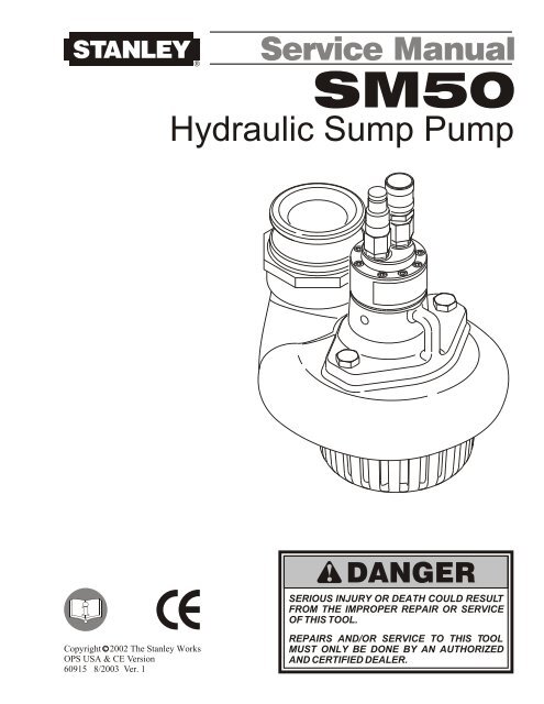
<strong>Service</strong> <strong>Manual</strong><br />
<strong>SM50</strong><br />
Hydraulic Sump Pump<br />
DANGER<br />
SERIOUS INJURY OR DEATH COULD RESULT<br />
FROM THE IMPROPER REPAIR OR SERVICE<br />
OF THIS TOOL.<br />
REPAIRS AND/OR SERVICE TO THIS TOOL<br />
MUST ONLY BE DONE BY AN AUTHORIZED<br />
AND CERTIFIED DEALER.
Table of Contents<br />
<strong>SM50</strong><br />
Hydraulic Sump Pump<br />
SERVICING THE<br />
<strong>SM50</strong> Sump Pump:<br />
This manual contains Safety,<br />
Operation, and Troubleshooting<br />
information. Stanley Hydraulic <strong>Tool</strong>s<br />
recommends that servicing of<br />
hydraulic tools, other than routine<br />
maintenance, must be performed<br />
by an authorized and certified<br />
dealer. Please read the DANGER<br />
warning on the cover and the<br />
c<br />
Copyright 2002 The Stanley Works<br />
All rights reserved.<br />
Under copyright law, this document may<br />
not be copied in whole or in part without<br />
the prior written consent of The Stanley<br />
Works. This exception does not permit<br />
copies to be made for others, whether or<br />
not sold. Under the law, copying includes<br />
translating into another language, format<br />
or medium. This copyright notice must<br />
appear on any permitted copies.<br />
Certificate of Conformity<br />
Specifications<br />
General Safety Instructions<br />
<strong>Tool</strong> Decals and Tags<br />
Hydraulic Hose Requirements<br />
HTMA Requirements<br />
Operating Instructions<br />
Troubleshooting<br />
Maintenance<br />
<strong>Service</strong> Instructions<br />
Parts Illustration<br />
Parts List<br />
Warranty<br />
SAFETY FIRST<br />
It is the responsibility of the operator and<br />
service technician to read rules and<br />
instructions for safe and proper operation<br />
and maintenance.<br />
A cautious worker using common sense is<br />
the greatest safety device.<br />
3<br />
4<br />
4<br />
5<br />
5<br />
7<br />
8<br />
9<br />
11<br />
13<br />
14<br />
17<br />
18<br />
19
I, the undersigned:<br />
Certificate of Conformity<br />
hereby certify that the construction plant or equipment specified hereunder:<br />
1. Category: Sump Pump<br />
2. Make: Stanley<br />
3. Type: <strong>SM50</strong><br />
4. Type Serial Number of equipment:<br />
5. Year of manufacture: Stamped on tool<br />
has been manufactured in conformity with- EEC Type examination as shown:<br />
Directive: EN 809<br />
Date: 1992<br />
6. Special Provisions: None<br />
Mellits, Kirk E.<br />
Surname and First Names<br />
Approved body: Self<br />
Date of expiration: N/A<br />
Done at: Stanley Hydraulic <strong>Tool</strong>s, Milwaukie, Oregon USA Date: 2002<br />
Signature: Position: Engineering Manager<br />
Weight______________________ 20 lbs. / 9.1 kg<br />
Overall Length________________ 10 in. / 25.4 cm<br />
Width________________________10 in. 25.4 cm<br />
Pressure Range_____1000-2000 psi / 70- 140 bar<br />
Flow Range_____________7-12<br />
gpm / 26-45 lpm<br />
System Type____<br />
Open Center, HTMA TYPE 2, 3<br />
Porting______________________ -8SAE O-Ring<br />
Couplers_________________ HTMA Flush Face<br />
Per NFPA T3.20.15/ISO 16028<br />
Water Outlet Size______________3.0 in. / 7.6 cm<br />
Specifications<br />
4<br />
HTMA Class II_____________7-9 gpm @ 2000 psi<br />
26 - 34 lpm @ 138 bar<br />
30Lpm at 138bar<br />
BHTMA CATEGORY<br />
40Lpm at 138bar<br />
EHTMA CATEGORY<br />
ALL<br />
EHTMA Category______30 lpm @ 138 bar<br />
EHTMA Category______40 lpm @ 138 bar<br />
HTMA Class III__________11-13 gpm @ 2000 psi<br />
42-49 lpm @ 138 bar<br />
Sound Pressure______________
General Safety Instructions<br />
Always observe safety symbols. They are included for your safety and the protection of the tool.<br />
This tool will provide safe and dependable service if operated in accordance with the instructions<br />
given in this manual. Read and understand this manual and any stickers and tags attached to the<br />
tool and hoses before operation. Failure to do so could result in personal injury or equipment<br />
damage.<br />
� Operator must start in a work area without bystanders. The operator must be familiar with all prohibited<br />
work areas such as excessive slopes and dangerous terrain conditions.<br />
�<br />
�<br />
�<br />
�<br />
�<br />
�<br />
�<br />
�<br />
�<br />
�<br />
�<br />
�<br />
�<br />
�<br />
�<br />
�<br />
�<br />
�<br />
DANGER<br />
This safety symbol may appear on<br />
the tool. It is used to alert the<br />
operator of an action that could<br />
place him/her or others in a life<br />
threatening situation.<br />
Establish a training program for all operators to ensure safe operations.<br />
Do not operate the tool unless thoroughly trained or under the supervision of an instructor.<br />
Always wear safety equipment such as goggles, head protection, and safety shoes at all times when<br />
operating the tool.<br />
Do not inspect or clean the tool while the hydraulic power source is connected. Accidental engagement of<br />
the tool can cause serious injury.<br />
Do not operate this tool without first reading the Operating Instructions.<br />
Do not install or remove this tool while the hydraulic power source is connected. Accidental engagement<br />
of the tool can cause serious injury.<br />
Never operate the tool if you cannot be sure that underground utilities are not present. Underground<br />
electrical utilities present an electrocution hazard. Underground gas utilities present an explosion hazard.<br />
Other underground utilities may present other hazards.<br />
Do not wear loose fitting clothing when operating the tool. Loose fitting clothing can get entangled with<br />
the tool and cause serious injury.<br />
Supply hoses must have a minimum working pressure rating of 2500 psi/175 bar.<br />
Be sure all hose connections are tight.<br />
WARNING<br />
This safety symbol appears in these<br />
instructions to identify an action<br />
that could cause bodily injury to the<br />
operator or other personnel.<br />
The hydraulic circuit control valve must be in the “OFF” position when coupling or uncoupling the tool.<br />
Wipe all couplers clean before connecting. Failure to do so may result in damage to the quick couplers<br />
and cause overheating. Use only lint-free cloths.<br />
Do not operate the tool at oil temperatures above 140 ° F/60 ° C. Operation at higher oil temperatures can<br />
cause operator discomfort and may cause damage to the tool.<br />
Do not operate a damaged, improperly adjusted, or incompletely assembled tool.<br />
To avoid personal injury or equipment damage, all tool repair, maintenance and service must only be<br />
performed by authorized and properly trained personnel.<br />
Do not exceed the rated limits of the tool or use the tool for applications beyond its design capacity.<br />
Always keep critical tool markings, such as labels and warning stickers legible.<br />
Always replace parts with replacement parts recommended by Stanley Hydraulic <strong>Tool</strong>s.<br />
Check fastener tightness often and before each use daily.<br />
5<br />
CAUTION<br />
This safety symbol appears in these<br />
instructions to identify an action or<br />
condition that could result in<br />
damage to the tool or other<br />
equipment.
A Name Tag Sticker is attached to the tool. Never exceed the flow and pressure levels specified on<br />
this sticker.The information listed on the name tag sticker must be legible at all times. Replace this<br />
sticker if it becomes worn or damaged. A replacement is available from your local Stanley<br />
distributor.<br />
The SAFETY TAG, P/N 15875, shown at right, smaller<br />
than actual size, is attached to the tool when shipped<br />
from the factory. Read and understand the safety<br />
instructions listed on this tag before removal. We<br />
suggest you retain this tag and attach it to the tool<br />
when not in use.<br />
<strong>Tool</strong> Decals & Tags<br />
6<br />
Model No.<br />
<strong>SM50</strong><br />
Stanley Hydraulic <strong>Tool</strong>s<br />
3810 S.E. Naef Road<br />
CAUTION<br />
® Milwaukie, Oregon 97267 U.S.A.<br />
4-12 GPM/ 15-43 LPM<br />
26-45 lpm/7-12 gpm<br />
DO NOT EXCEED 2000 PSI/ 140 BAR<br />
138 bar/2000 psi<br />
DANGER DANGER<br />
1. FAILURE TO USE HYDRAULIC HOSE LABELED AND<br />
CERTI-FIED AS NON-CONDUCTIVE WHEN USING<br />
HYDRAULIC TOOLS ON OR NEAR ELECTRICAL LINES<br />
MAY RESULT IN DEATH OR SERIOUS INJURY.<br />
BEFORE USING HOSE LABELED AND CERTIFIED AS<br />
NON- CONDUCTIVE ON OR NEAR ELECTRIC LINES.<br />
BE SURE THE HOSE IS MAINTAINED AS NON- CONDUC TIVE . THE<br />
HOSE SHOULD BE REGULARLY TESTED FOR ELECTRIC CURRENT<br />
LEAKAGE IN ACCORDANCE WITH YOUR SAFETY DEPARTMENT<br />
INSTRUCTIONS.<br />
2. A HYDRAULIC LEAK OR BURST MAY CAUSE OIL<br />
INJECTION INTO THE BODY OR CAUSE OTHER SEVERE PERSONAL<br />
INJURY.<br />
A.DO NOT EXCEED SPECIFIED FLOW AND<br />
PRESSURE FOR THIS TOOL. EXCESS FLOW OR<br />
PRESSURE MAY CAUSE A LEAK OR BURST.<br />
B. DO NOT EXCEED RATED WORKING PRESSURE<br />
OF HYDRAULIC HOSE USED WITH THIS TOOL.<br />
EXCESS PRESSURE MAY CAUSE A LEAK OR<br />
BURST.<br />
C. CHECK TOOL, HOSE, COUPLERS &<br />
C O N N E C T O R S D A I L Y F O R<br />
LEAKS. DO NOT FEEL FOR LEAKS WITH<br />
YOUR HANDS. CONTACT WITH A LEAK MAY<br />
RESULT IN SEVERE PERSONAL INJURY.<br />
D. DO NOT LIFT OR CARRY TOOL BY THE HOSES. DO NOT ABUSE<br />
HOSE. DO NOT USE KINKED, TORN OR DAMAGED HOSES.<br />
3. MAKE SURE HYDRAULIC HOSES ARE PROPERLY<br />
CONN-ECTED TO THE TOOL BEFORE PRESSURIZING<br />
SYSTEM. SYSTEM PRESSURE HOSE MUST ALWAYS<br />
BE CONNECTED TO TOOL “IN” PORT. SYSTEM<br />
RETURN HOSE MUST ALWAYS BE CONNECTED AT<br />
TOOL “OUT” PORT. REVERSING CONNECTIONS MAY<br />
CAUSE REVERSE TOOL OPERATION WHICH CAN<br />
CAUSE SEVERE PERSONAL INJURY.<br />
4. DO NOT CONNECT CLOSED-CENTER TOOLS TO<br />
OPEN-CENTER HYDRAULIC SYSTEMS. THIS MAY<br />
CAUSE EXTREME SYSTEM HEAT AND/OR SEVERE<br />
PERSONAL INJURY.<br />
DO NOT CONNECT OPEN-CENTER TOOLS TO CLO SE D- CE NT ER<br />
HYDRAULIC SYSTEMS. THIS MAY RESULT IN LOSS OF OTHER<br />
HYDRAULIC FUNCTIONS POWERED BY THE SAME SYSTEM AND/OR<br />
SEVERE PERSONAL INJURY.<br />
5. BYSTANDERS MAY BE INJURED IN YOUR WORK<br />
AREA. KEEP BYSTANDERS CLEAR OF YOUR WORK<br />
AREA.<br />
6. WEAR HEARING, EYE, FOOT, HAND AND HEAD PROTECTION.<br />
7. TO AVOID PERSONAL INJURY OR EQUIPMENT DAMAGE, ALL TOOL<br />
REPAIR, MAINTENANCE AND SERVICE MUST BE<br />
PERFORMED BY AUTHORIZED AN D PR OP ER LY<br />
TRAINED PERSONNEL.<br />
IMPORTANT IMPORTANT<br />
READ OPERATION MANUAL AND<br />
SAFETY INSTRUCTIONS FOR THIS<br />
TOOL BEFORE USING IT.<br />
USE ONLY PARTS AND REPAIR<br />
PROCEDURES APPROVED BY<br />
STANLEY AND DESCRIBED IN THE<br />
OPERATION MANUAL.<br />
30Lpm at 138bar<br />
BHTMA CATEGORY<br />
40Lpm at 138bar<br />
BHTMA CATEGORY<br />
HTMA TYPE II HTMA TYPE III<br />
52728<br />
<strong>SM50</strong> Combined Sticker<br />
READ OPERATION MANUAL AND<br />
SAFETY INSTRUCTIONS FOR THIS<br />
TOOL BEFORE USING IT.<br />
USE ONLY PARTS AND REPAIR<br />
PROCEDURES APPROVED BY<br />
STANLEY AND DESCRIBED IN THE<br />
OPERATION MANUAL.<br />
TAG TO BE REMOVED ONLY BY TOOL<br />
OPERATOR.<br />
TAG TO BE REMOVED ONLY BY TOOL<br />
OPERATOR.<br />
(517) SEE OTHER SIDE 15875 (517)<br />
SEE OTHER SIDE<br />
15875
HOSE TYPES<br />
Hydraulic Hose Requirements<br />
Hydraulic hose types authorized for use with Stanley Hydraulic <strong>Tool</strong>s are as follows:<br />
Certified non-conductive<br />
Wire-braided (conductive)<br />
Fabric-braided (not certified or labeled non-conductive)<br />
Hose listed above is the only hose authorized for use near electrical conductors.<br />
Hoses and listed above are conductive and must never be near electrical conductors.<br />
HOSE SAFETY TAGS<br />
To help ensure your safety, the following DANGER tags are attached to all hoses purchased from Stanley<br />
Hydraulic <strong>Tool</strong>s. DO NOT REMOVE THESE TAGS.<br />
If the information in a tag is illegible because of wear or damage, replace the tag immediately. A new tag<br />
may be obtained at no charge from your Stanley Distributor.<br />
DO NOT REMOVE THIS TAG<br />
DO NOT REMOVE THIS TAG<br />
1.<br />
2.<br />
3.<br />
1.<br />
2.<br />
4. HANDLE AND ROUTE HOSE CAREFULLY TO AVOID KINKING, ABRASION, CUTTING OR CONTACT<br />
WITH HIGH TEMPERATURE SURFACES. DO NOT USE IF KINKED. DO NOT USE HOSE TO PULL OR<br />
LIFT TOOLS, POWER UNITS, ETC.<br />
SEE OTHER SIDE<br />
HOSE PRESSURE RATING<br />
This Tag attached to “Certified Non-Conductive” hose.<br />
(shown smaller than actual size) p/n 27987<br />
DANGER<br />
FAILURE TO USE HYDRAULIC HOSE LABELED AND CERTIFIED AS NON-CONDUCTIVE WHEN USING<br />
HYDRAULIC TOOLS ON OR NEAR ELECTRIC LINES MAY RESULT IN DEATH OR SERIOUS INJURY.<br />
FOR PROPER AND SAFE OPERATION, MAKE SURE THAT YOU HAVE BEEN PROPERLY TRAINED IN<br />
CORRECT PROCEDURES REQUIRED FOR WORK ON OR AROUND ELECTRIC LINES.<br />
BEFORE USING HYDRAULIC HOSE LABELED AND CERTIFIED AS NON-CONDUCTIVE ON OR NEAR<br />
ELECTRIC LINES, WIPE THE ENTIRE LENGTH OF THE HOSE AND FITTINGS WITH A CLEAN,<br />
DRY, ABSORBENT CLOTH TO REMOVE DIRT AND MOISTURE AND TEST HOSE FOR MAXIMUM<br />
ALLOWABLE CURRENT LEAKAGE IN ACCORDANCE WITH SAFETY DEPARTMENT INSTRUCTIONS.<br />
DO NOT EXCEED HOSE WORKING PRESSURE OR ABUSE HOSE. IMPROPER USE OR HANDLING OF<br />
HOSE COULD RESULT IN BURST OR OTHER HOSE FAILURE. KEEP HOSE AS FAR AWAY AS<br />
POSSIBLE FROM BODY AND DO NOT PERMIT DIRECT CONTACT DURING USE. CONTACT AT THE<br />
BURST CAN CAUSE BODILY INJECTION AND SEVERE PERSONAL INJURY.<br />
SEE OTHER SIDE<br />
DANGER<br />
4. HANDLE AND ROUTE HOSE CAREFULLY TO AVOID KINKING, ABRASION, CUTTING OR CONTACT<br />
WITH HIGH TEMPERATURE SURFACES. DO NOT USE IF KINKED. DO NOT USE HOSE TO PULL OR<br />
LIFT TOOLS, POWER UNITS, ETC.<br />
CHECK ENTIRE HOSE FOR CUTS, CRACKS, LEAKS, ABRASIONS, BULGES OR DAMAGE TO<br />
COUPLINGS. IF ANY OF THESE CONDITIONS EXIST, REPLACE THE HOSE IMMEDIATELY.<br />
NEVER USE TAPE OR ANY DEVICE TO ATTEMPT TO MEND THE HOSE.<br />
6. AFTER EACH USE, STORE IN A CLEAN, DRY AREA.<br />
The rated working pressure of the hydraulic hose must be equal to or higher than the relief valve setting on<br />
the hydraulic system.<br />
5.<br />
5.<br />
SEE OTHER SIDE<br />
Side 1 Side 2<br />
This Tag attached to “Conductive” hose.<br />
(shown smaller than actual size) p/n 29144<br />
DANGER<br />
DO NOT USE THIS HYDRAULIC HOSE ON OR NEAR ELECTRIC LINES. THIS HOSE IS NOT<br />
LABELED OR CERTIFIED AS NON-CONDUCTIVE. USING THIS HOSE ON OR NEAR ELECTRIC LINES<br />
MAY RESULT IN DEATH OR SERIOUS INJURY.<br />
FOR PROPER AND SAFE OPERATION, MAKE SURE THAT YOU HAVE BEEN PROPERLY TRAINED IN<br />
CORRECT PROCEDURES REQUIRED FOR WORK ON OR AROUND ELECTRIC LINES.<br />
3. DO NOT EXCEED HOSE WORKING PRESSURE OR ABUSE HOSE. IMPROPER USE OR HANDLING OF<br />
HOSE COULD RESULT IN BURST OR OTHER HOSE FAILURE. KEEP HOSE AS FAR AWAY AS<br />
POSSIBLE FROM BODY AND DO NOT PERMIT CONTACT DURING USE. CONTACT AT THE<br />
BURST CAN CAUSE BODILY INJECTION AND SEVERE PERSONAL INJURY.<br />
DANGER<br />
CHECK ENTIRE HOSE FOR CUTS, CRACKS, LEAKS, ABRASIONS, BULGES OR DAMAGE TO<br />
COUPLINGS. IF ANY OF THESE CONDITIONS EXIST, REPLACE THE HOSE IMMEDIATELY.<br />
NEVER USE TAPE OR ANY DEVICE TO ATTEMPT TO MEND THE HOSE.<br />
6. AFTER EACH USE, STORE IN A CLEAN, DRY AREA.<br />
SEE OTHER SIDE<br />
Side 1 Side 2<br />
7<br />
DO NOT REMOVE THIS TAG<br />
DO NOT REMOVE THIS TAG
Hydraulic System<br />
Requirements<br />
Flow rate<br />
<strong>Tool</strong> Operating Pressure<br />
(at the power supply outlet)<br />
System relief valve setting<br />
(at the power supply outlet)<br />
Maximum back pressure<br />
(at tool end of the return hose)<br />
Measured at a max. fluid viscosity of:<br />
(at min. operating temperature)<br />
Temperature<br />
Sufficient heat rejection capacity<br />
to limit max. fluid temperature to:<br />
(at max. expected ambient temperature)<br />
Min. cooling capacity<br />
at a temperature difference of<br />
between ambient and fluid temps<br />
NOTE: Do not operate the tool at oil<br />
temperatures above 140°<br />
F (60° C). Operation<br />
at higher temperatures can cause operator<br />
discomfort at the tool.<br />
Filter<br />
Min. full-flow filtration<br />
Sized for flow of at least:<br />
(For cold temp. startup and max. dirt-holding<br />
capacity)<br />
Hydraulic fluid<br />
Petroleum based<br />
(premium grade, anti-wear, non-conductive)<br />
Viscosity<br />
(at min. and max. operating temps)<br />
NOTE: When choosing hydraulic fluid, the<br />
expected oil temperature extremes that will be<br />
experienced in service determine the<br />
most suitable temperature viscosity<br />
characteristics. Hydraulic fluids with a viscosity<br />
index over 140 will meet the requirements over<br />
a wide range of operating temperatures.<br />
HTMA Requirements<br />
C<br />
20Lpm at 138bar<br />
BHTMA CATEGORY<br />
Type I<br />
8<br />
30Lpm at 138bar<br />
BHTMA CATEGORY<br />
Type II<br />
<strong>Tool</strong> Category<br />
Type III<br />
4-6 gpm 7-9 gpm 10.5-11.6 gpm 11-13 gpm<br />
(15-23 lpm) (26-34 lpm) (36-44 lpm) (42-49 lpm)<br />
2000 psi 2000 psi 2000 psi 2000 psi<br />
(138 bar) (138 bar) (138 bar) (138 bar)<br />
2100-2250 psi<br />
(145-155 bar)<br />
200 psi<br />
(14 bar)<br />
400 ssu*<br />
(82 centistokes)<br />
40Lpm at 138bar<br />
EHTMA CATEGORY<br />
2100-2250 psi 2100-2250 psi 2100-2250 psi<br />
(145-155 bar) (145-155 bar) (145-155 bar)<br />
200 psi 200 psi 200 psi<br />
(14 bar) (14 bar) (14 bar)<br />
400 ssu* 400 ssu* 400 ssu*<br />
(82 centistokes) (82 centistokes) (82 centistokes)<br />
140° F (60° C) 140° F (60° C) 140° F (60° C) 140°<br />
F (60° C)<br />
3 hp (2.24 kW) 5 hp (3.73 kW) 6 hp (4.47 kW) 7 hp (5.22 kW)<br />
40° F (22° C) 40° F (22° C) 40° F (22° C) 40°<br />
F (22° C)<br />
25 microns 25 microns 25 microns 25 microns<br />
18 gpm (68 lpm) 30 gpm (114 lpm) 35 gpm (132 lpm) 40 gpm (151 lpm)<br />
100-400 ssu* 100-400 ssu* 100-400 ssu* 100-400 ssu*<br />
(20-82 centistokes) (20-82 centistokes) (20-82 centistokes) (20-82 centistokes)<br />
NOTE: These are general hydraulic system requirements. See tool Specification page for tool<br />
specific requirements.
Pre-operation Procedures<br />
Check Power Source<br />
1. Using a calibrated flow meter and pressure<br />
gauge, check that the hydraulic power source<br />
develops a flow of 7-12 gpm / 26-45 lpm at<br />
1000-2000 psi / 70-140 bar.<br />
2. Make certain that the power source is<br />
equipped with a relief valve set to crack at<br />
2100 psi / 145 bar maximum.<br />
3. Check that the pump inlet screen and outlet<br />
hose are clean. Remove any obstruction<br />
before operating the pump. Refer to PUMP<br />
CLEANING PROCEDURES.<br />
Connect Hoses<br />
1. Wipe all hose couplers with a clean, lint free<br />
cloth before making connections.<br />
2. Connect the hoses from the power supply to<br />
the tool fittings. It is a good practice to<br />
connect return hoses first and disconnect last<br />
to minimize or avoid trapped pressure within<br />
the tool.<br />
3. If hose couplers are used, observe the arrow<br />
on the coupler to ensure that the flow is in the<br />
proper direction. The female coupler on the<br />
tool port is the inlet pressure coupler. This<br />
coupler should be connected to the port<br />
closest to the water outlet.<br />
Pump Operation<br />
CAUTION<br />
Observe the following for Equipment protection and care.<br />
Note: The <strong>SM50</strong> pump is NOT DESIGNED<br />
FOR USE WITH A SUCTION PIPE INLET.<br />
The diameter of the suction screen at the<br />
bottom of the pump provides maximum<br />
pump efficiency. Reducing the size of this<br />
inlet will greatly reduce pump<br />
Operating Instructions<br />
9<br />
performance.<br />
1. Connect a hose fitted with a 3 in. / 76.2 mm<br />
female camlock coupler to the pump outlet<br />
fitting. Make sure the fitting is securely<br />
tightened.<br />
2. Lower the pump into the liquid to be pumped.<br />
Locate the outlet end of the discharge hose to<br />
disperse the liquid as required. Remove any<br />
kinks from the hose to assure maximum water<br />
flow.<br />
3. Energize the power source. Watch for solids in<br />
the liquid being pumped. If solids are<br />
excessive, the discharge flow may decrease. If<br />
this happens, stop the pump and check for the<br />
cause of the problem.<br />
Under some conditions, the liquid being pumped<br />
may be slowed enough so that it can no longer<br />
push particles in the liquid. If this happens,<br />
particles can accumulate in the hose and back<br />
up to the pumping chamber, causing further<br />
restriction. The impeller then acts as a "grinding<br />
wheel" which causes accelerated pump wear.<br />
Reduced liquid flow can be caused by the<br />
following:<br />
�<br />
�<br />
�<br />
WARNING<br />
Never Point the end of the hose at bystanders.<br />
The pump sinks into solids at the bottom of<br />
the hole.<br />
The end of the outlet hose is too high, causing<br />
excessive lift height for the column of liquid<br />
being pushed by the pump. This slows the<br />
flow of liquid to a level where it can no longer<br />
carry solids out the hose end.<br />
The flow and pressure of hydraulic oil to the<br />
pump is too low which reduces impeller<br />
speed. A 20 percent decrease in hydraulic oil<br />
flow can reduce pump performance by 50<br />
percent. When operating at reduced hydraulic<br />
flow and pressure, the end of the outlet hose<br />
should not be more than 30 feet above the
Operating Instructions<br />
liquid.<br />
4. When pumping is completed, set the hydraulic<br />
flow control valve at the power source to<br />
OFF, then lift the pump from the hole or<br />
chamber.<br />
Cold Weather Operation<br />
If the pump is to be used during cold weather,<br />
preheat the hydraulic oil at low engine speed prior<br />
to use, when using the normally recommended<br />
oils, oil should be at or above 50°F / 10°C (400<br />
ssu / 82 centistokes) before use. Damage to the<br />
hydraulic system or pump can result from the use<br />
with oil that is too viscous or thick.<br />
10
Pump will not<br />
start.<br />
Troubleshooting<br />
This section describes how to find and resolve problems users may experience. If a situation occurs that is<br />
not covered, call your Stanley Customer <strong>Service</strong> representative for assistance.<br />
Symptom Possible Cause Solution<br />
Poor pump<br />
performance.<br />
WARNING<br />
Inspecting the tool or installing parts with the hydraulic hoses connected can result in severe personal injury or equipment<br />
damage.<br />
To prevent accidental startup, disconnect the hydraulic power before beginning any inspection or installation task.<br />
If symptoms of poor performance develop, the following chart can be used as a guide to correct the problem.<br />
When diagnosing faults in operation of the tool, always check that the hydraulic power source is supplying<br />
the correct hydraulic flow and pressure to the tool as listed in the table. Use a flowmeter known to be<br />
accurate. Check the flow with the hydraulic oil temperature at least 80° F/27° C.<br />
No hydraulic flow or pressure. Turn on power unit and check that<br />
7-12 gpm / 26-45 lpm at 1000-2000<br />
psi / 70-140 bar is available at the<br />
pump.<br />
Defective couplers. Check the couplers. Replace, if<br />
necessary.<br />
Impeller jammed with debris. Clean the pumping chamber as<br />
described in the MAINTENANCE<br />
section of the manual.<br />
Defective hydraulic motor. Repair or replace motor.<br />
Hydraulic flow reversed. Check that hoses are correctly<br />
connected to the pump motor ports.<br />
The pressure hose should be<br />
connected to the IN port. The return<br />
oil must never flow through a<br />
reversing valve.<br />
Low hydraulic oil flow. Check that 7-12 gpm / 26-45 lpm at<br />
1000-2000 psi / 70 -140 bar is<br />
available at the pump. A 20 percent<br />
decrease in flow can result in a 50<br />
percent decrease in pump<br />
performance.<br />
Pump submersed in sediment. Lift the pump from the bottom of<br />
the hole or chamber. Use a flat<br />
support under the pump if<br />
necessary.<br />
Pump inlet restricted. Remove the suction screen and<br />
clean thoroughly. Reassemble.<br />
11<br />
continued
Symptom<br />
Poor pump<br />
performance.<br />
(continued)<br />
Poor pump performance<br />
with<br />
excessive wear.<br />
Troubleshooting<br />
Possible Cause Solution<br />
Discharge hose kinked or<br />
restricted.<br />
12<br />
Straighten the hose. If hose must<br />
bend at top of hole, use a bend of<br />
split rigid conduit with a diameter<br />
large enough to accept the<br />
diameter of the expanded hose.<br />
This will keep the hose from kinking.<br />
Check for debris inside the hose.<br />
Clean as required.<br />
Discharge hose too small. Use 3 in./ 76.2 mm diameter<br />
fire hose.<br />
Water lift too high for gpm supply<br />
from hydraulic power source.<br />
Lower the outlet end of the discharge<br />
hose.<br />
Increase hydraulic flow<br />
(12 gpm / 45 lpm max.)<br />
Pump not matched to application. Obtain higher capacity pump.<br />
Impeller worn or damaged. Check for impeller damage and<br />
excessive wear. Replace the<br />
impeller if necessary.<br />
Hose used on suction side of<br />
pump.<br />
Too many solids in the water.<br />
Water speed out of the hose may<br />
be too slow, therefore hose and<br />
pump load up with solids.<br />
Remove. Use no plumbing on<br />
suction side of pump.<br />
Reduce solids content. Increase<br />
pump speed.
Cleaning the Pumping Chamber<br />
Debris such as weeds, sand and other solids may<br />
become trapped in the water hose and pumping<br />
chamber. This can reduce pump performance. It is<br />
important that the pumping chamber be kept clean<br />
at all times. The chamber can be cleaned as<br />
follows:<br />
1. Remove motor and impeller by removing the<br />
two M12 x 1.75 Hex Head capscrews.<br />
2. Remove all debris from the pump screen.<br />
3. Thoroughly clean the volute and impeller. Do<br />
not remove the impeller unless necessary for<br />
repair or replacement or to remove trapped<br />
debris.<br />
Maintenance<br />
WARNING<br />
Inspecting the tool or installing parts with the hydraulic hoses connected can result in severe personal injury or equipment<br />
damage.<br />
To prevent accidental startup, disconnect the hydraulic power before beginning any inspection or installation task.<br />
13<br />
4. Assemble the motor and impeller to the<br />
volute. Clean the capscrews and lubricate the<br />
threads with underwater grease before<br />
installation.<br />
5. Remove all debris from the hose. Otherwise,<br />
solids will backfill the pump.
<strong>Tool</strong> Disassembly / Reassembly<br />
Note: For orientation of parts in the following<br />
procedures, refer to the parts drawing later in<br />
this manual.<br />
Prior to Disassembly<br />
1. Clean the exterior of the tool and place on a clean<br />
work surface.<br />
2. Obtain the seal kit listed on the PARTS LIST so all<br />
seals exposed during disassembly can be replaced.<br />
Prior to Reassembly<br />
1. Clean all parts with a degreasing solution<br />
2. Blow dry all parts or use lint-free cloths.<br />
3. Ensure that all seals exposed during disassembly<br />
are replaced with new parts.<br />
4. Apply clean grease or o-ring lubricant to all parts<br />
during assembly.<br />
<strong>Tool</strong> Disassembly<br />
Volute<br />
1. Remove the volute (1) by first removing the hex<br />
head cap screws (25) and pulling the motor and<br />
impeller off the volute.<br />
Impeller<br />
1. Remove hex socket head capscrew (3) and washer<br />
(4) before lifting impeller (5) off motor assembly.<br />
2. Remove key (18) and shim stack (7 & 8) from<br />
impeller.<br />
Motor Cap<br />
<strong>Service</strong> Instructions<br />
14<br />
1. Remove the hex socket head capscrews (33) that<br />
secure the motor cap (31) to the front bearing<br />
housing (24) and remove the motor cap. Do not in<br />
any way excessively force the motor cap off the<br />
front bearing housing.<br />
2. Remove the o-ring (26) from the motor cap.<br />
Drive Shaft<br />
1. Remove idler gear (29), idler shaft (30), drive<br />
gear (28), and needle roller (19) from front bearing<br />
housing.<br />
2. Remove the v-ring (6) from the seal race (14)<br />
before pulling the seal race off the drive shaft.<br />
3. Remove retaining ring (9).<br />
4. Using a pick, remove the seal carrier (10), cup<br />
seal (12), o-ring (11), seal retainer (13), and o-ring<br />
(15) from the bearing cavity.<br />
5. Press the drive shaft (17) and bearings (16) from<br />
the front bearing housing.<br />
6. Spin the ball bearings on the drive shaft. The<br />
bearing should turn smoothly. To replace the<br />
bearing, support the outer race and press down on<br />
the drive shaft from the threaded end. Do not reuse<br />
the ball bearing once it has been removed from the<br />
drive shaft.<br />
Drive Shaft Seal<br />
1. Remove the retaining ring (20), quad ring (21),<br />
seal gland (22) and o-ring (23) from the drive shaft<br />
bore using a pick.<br />
Cleaning and Inspection<br />
Cleaning<br />
Clean all parts with a degreasing solution. Blow dry<br />
with compressed air or use lint-free cloths.
Gear Chamber (Motor Cap)<br />
The chamber bores and bottoms around the shaft<br />
bushings should be polished and not rough or<br />
grooved. If the bushing bores are yellow-bronze,<br />
replace them and investigate the cause of wear.<br />
The flat surfaces around the chamber and bolt holes<br />
should be flat and free of nicks or burrs that could<br />
cause misalignment or leaks.<br />
Bushings<br />
The inside of the bushings should be gray with some<br />
bronze showing through. If significant yellowbronze<br />
shows, replace the bushings. Inspect the<br />
motor shaft and idler shaft for corresponding wear<br />
and replace as required.<br />
Gears<br />
The drive and idler gears should have straight tips<br />
without nicks, square tooth ends, and a smooth even<br />
polish on the teeth and end faces. Replace the gear if<br />
cracks are present.<br />
Front Bearing Housing<br />
The surface near the gears should show two<br />
interconnecting polished circles without a step.<br />
Shafts<br />
The shaft diameter at the bearing and seal locations<br />
must be smooth. Grooves, roughness or a reduced<br />
diameter indicate fluid contamination or damaged<br />
bushings. Grit particles may have been imbedded in<br />
the bushings, grinding into the hardened shaft. If<br />
abnormal shaft wear as noted above occurs (more<br />
than normal polishing), replace both the shaft and<br />
associated bushings.<br />
Also check the hydraulic system for excess<br />
contamination in the fluid and for filter condition.<br />
Operating conditions may require changing from a<br />
25-micron filter to an oversized 10-micron filter.<br />
<strong>Service</strong> Instructions<br />
15<br />
<strong>Tool</strong> Reassembly<br />
Drive Shaft Seal<br />
1. Heavily lubricate and install a new o-ring (23) and<br />
quad ring (21) into seal gland (22). Ensure the quad<br />
ring is not twisted during assembly.<br />
2. Install seal gland and attached parts into front<br />
bearing housing and secure with retaining ring (20).<br />
Drive Shaft<br />
1 Install bearings (16) onto lubricated drive shaft (17)<br />
by supporting the inner races of the bearings and<br />
pressing drive shaft through bearings until the<br />
bearings rest against the shoulder. Installation by the<br />
outer race will cause bearing damage.<br />
2. Pack grease into needle roller groove on drive shaft<br />
and insert drive shaft into the seal gland. Using a<br />
bearing pusher or a sleeve / socket with a diameter<br />
slightly smaller than the bearing bore, press the<br />
bearing assembly into place using the outer race.<br />
Installation by the inner race will result in bearing<br />
damage.<br />
3. Lubricate and install o-ring (15) and seal race (14)<br />
onto driveshaft.<br />
4. Lubricate and install seal retainer (13) and o-ring<br />
(11) into bearing bore.<br />
5. Heavily lubricate with underwater grease and<br />
install cup seal (12) and seal carrier (10) into bearing<br />
bore and secure with retaining ring (9). Installation of<br />
seal carrier and cup seal before seal race has been<br />
installed will result in damage to cup seal.<br />
6. Lubricate with underwater grease and install v-ring<br />
(6) onto seal race.<br />
7. Install idler shaft (30) and idler gear (29).<br />
8. Use grease to hold needle roller (19) in place before<br />
installing drive gear (28).
Motor Cap<br />
1. Lubricate and install o-ring (26) into motor cap<br />
(31).<br />
2. Lubricate hex socket head capscrews (33) with an<br />
antiseize compound and install motor cap to front<br />
bearing housing. Tighten capscrews to 8-10 ft.lb.<br />
Note the orientation of the motor cap as the bolt<br />
holes will only line up one way.<br />
Impeller<br />
CAUTION<br />
Do not force parts together.<br />
1. Install shim stack (7&8) onto drive shaft.<br />
2. Install key (18) and impeller (5) to drive shaft and,<br />
using loctite, secure with washer (4) and hex socket<br />
head capscrew (3). Tighten capscrew to 15 ft.lb.<br />
3. Using a depth mic, measure the distance from the<br />
bottom of the motor flange to the bottom of the<br />
stepped diameter as shown below. Adjust shim stack<br />
accordingly to achieve a 2.285 / 2.270 offset.<br />
<strong>Service</strong> Instructions<br />
16<br />
Volute<br />
1. Assemble motor and impeller to volute (1) and<br />
secure with hex head cap screws (25).<br />
2. Use an allen wrench to ensure that the impeller<br />
with freewheel after assembly.
32<br />
24<br />
36<br />
28<br />
27<br />
26<br />
23<br />
22<br />
21<br />
20<br />
<strong>SM50</strong> Parts Illustration<br />
25<br />
35<br />
34<br />
33<br />
31<br />
30<br />
29<br />
17<br />
18<br />
19<br />
4<br />
3<br />
17<br />
16<br />
15<br />
14<br />
13<br />
12<br />
11<br />
10<br />
9<br />
6<br />
8<br />
7<br />
5<br />
1<br />
2
NOTE:<br />
Use Part Number and<br />
Description when ordering.<br />
Accessories<br />
59101 Adapter, 2-1/2 Inch Male NPT<br />
/3 Inch Male Groove<br />
<strong>SM50</strong> Parts List<br />
Item Part Description Qty.<br />
1<br />
2<br />
3<br />
4<br />
5<br />
6<br />
7<br />
8<br />
9<br />
10<br />
11<br />
12<br />
13<br />
14<br />
15<br />
16<br />
17<br />
18<br />
19<br />
20<br />
21<br />
22<br />
23<br />
24<br />
25<br />
26<br />
27<br />
28<br />
29<br />
30<br />
31<br />
32<br />
33<br />
34<br />
35<br />
36<br />
18<br />
52669<br />
52720<br />
13815<br />
56763<br />
52671<br />
52716<br />
31032<br />
31033<br />
00166<br />
52719<br />
01262<br />
58651<br />
56658<br />
56697<br />
01211<br />
00148<br />
52696<br />
00635<br />
06881<br />
00170<br />
00669<br />
19884<br />
00171<br />
52693<br />
52718<br />
00178<br />
06316<br />
06853<br />
06855<br />
06854<br />
06857<br />
52728<br />
00612<br />
00936<br />
24058<br />
24059<br />
52758<br />
00148<br />
00635<br />
06881<br />
13815<br />
56763<br />
52759<br />
52759<br />
00171<br />
00178<br />
00669<br />
01211<br />
01262<br />
19884<br />
52716<br />
58651<br />
Volute<br />
Camlock Coupling 3 in.<br />
HSHCS 5/16 - 18 x 3/4<br />
Washer<br />
Impeller<br />
V-Ring<br />
Shim .020<br />
Shim .010<br />
Retaining Ring<br />
Seal Carrier<br />
O-ring 1-3/4 x 1-7/8 x 1/16 -031<br />
Cup Seal<br />
Seal Retainer<br />
Seal Race<br />
O-ring 5/8 x 3/4 x 1/16 -016<br />
Bearing<br />
Drive Shaft<br />
Key<br />
Needle Roller<br />
Retaining Ring<br />
Quad Ring 1/2 x 5/8 x 1/16 - 014<br />
Seal Gland<br />
O-Ring 11/16 x 13/16 x 1/16 - 017<br />
Front Bearing Housing<br />
HHCS M12-1.75 x 30mm<br />
O-ring 2-1/8 x 2-1/4 x 1/16 - 034<br />
Bushing<br />
Drive Gear<br />
Idler Gear<br />
Idler Shaft<br />
Gear Housing<br />
Name Tag and Safety Sticker<br />
HSHCS 1/4-20 x 2-1/4<br />
Adapter<br />
Flush Face Coupler Body 3/8 NPT<br />
Flush Face Coupler Nose 3/8 NPT<br />
Repair Kit<br />
Bearing<br />
Key<br />
Needle Roller<br />
HSHCS<br />
Washer<br />
Seal Kit<br />
Seal Kit<br />
O-Ring 11/16 x 13/16 x 1/16 - 017<br />
O-ring 2-1/8 x 2-1/4 x 1/16 - 034<br />
Quad Ring 1/2 x 5/8 x 1/16 - 014<br />
O-ring<br />
O-ring<br />
Seal Gland<br />
V-Ring<br />
Cup Seal<br />
1<br />
1<br />
1<br />
1<br />
1<br />
1<br />
*<br />
*<br />
1<br />
1<br />
1<br />
1<br />
1<br />
1<br />
1<br />
2<br />
1<br />
1<br />
1<br />
1<br />
1<br />
1<br />
1<br />
1<br />
2<br />
1<br />
2<br />
1<br />
1<br />
1<br />
1<br />
1<br />
8<br />
2<br />
1<br />
1<br />
2<br />
1<br />
1<br />
1<br />
1<br />
1<br />
1<br />
1<br />
1<br />
1<br />
1<br />
1<br />
1<br />
1
Warranty<br />
Stanley Hydraulic <strong>Tool</strong>s (hereinafter called “Stanley”), subject to the exceptions contained below, warrants new hydraulic tools for a period of one<br />
year from the date of sale to the first retail purchaser, or for a period of 2 years from the shipping date from Stanley, whichever period expires first,<br />
to be free of defects in material and/or workmanship at the time of delivery, and will, at its option, repair or replace any tool or part of a tool, or new<br />
part, which is found upon examination by a Stanley authorized service outlet or by Stanley’s factory in Milwaukie, Oregon to be DEFECTIVE IN<br />
MATERIAL AND/OR WORKMANSHIP.<br />
EXCEPTIONS FROM WARRANTY<br />
NEW PARTS: New parts which are obtained individually are warranted, subject to the exceptions herein, to be free of defects in material and/or<br />
workmanship at the time of delivery and for a period of 6 months after the date of first usage. Seals and diaphragms are warranted to be free of<br />
defects in material and/or workmanship at the time of delivery and for a period of 6 months after the date of first usage or 2 years after the date of<br />
delivery, whichever period expires first. Warranty for new parts is limited to replacement of defective parts only. Labor is not covered.<br />
FREIGHT COSTS: Freight costs to return parts to Stanley, if requested by Stanley for the purpose of evaluating a warranty claim for warranty<br />
credit, are covered under this policy if the claimed part or parts are approved for warranty credit. Freight costs for any part or parts which are not<br />
approved for warranty credit will be the responsibility of the individual.<br />
SEALS & DIAPHRAGMS: Seals and diaphragms installed in new tools are warranted to be free of defects in material and/or workmanship for a<br />
period of 6 months after the date of first usage, or for a period of 2 years from the shipping date from Stanley, whichever period expires first.<br />
CUTTING ACCESSORIES: Cutting accessories such as breaker tool bits are warranted to be free of defects in material and or workmanship at<br />
the time of delivery only.<br />
ITEMS PRODUCED BY OTHER MANUFACTURERS: Components which are not manufactured by Stanley and are warranted by their respective<br />
manufacturers.<br />
a. Costs incurred to remove a Stanley manufactured component in order to service an item manufactured by other<br />
manufacturers.<br />
ALTERATIONS & MODIFICATIONS: Alterations or modifications to any tool or part. All obligations under this warranty shall be terminated if the<br />
new tool or part is altered or modified in any way.<br />
NORMAL WEAR: Any failure or performance deficiency attributable to normal wear and tear such as tool bushings, retaining pins, wear plates,<br />
bumpers, retaining rings and plugs, rubber bushings, recoil springs, etc.<br />
INCIDENTAL/CONSEQUENTIAL DAMAGES: To the fullest extent permitted by applicable law, in no event will STANLEY be liable for any<br />
incidental, consequential or special damages and/or expenses.<br />
FREIGHT DAMAGE: Damage caused by improper storage or freight handling.<br />
LOSS TIME: Loss of operating time to the user while the tool(s) is out of service.<br />
IMPROPER OPERATION: Any failure or performance deficiency attributable to a failure to follow the guidelines and/or procedures as outlined in<br />
the tool’s operation and maintenance manual.<br />
MAINTENANCE: Any failure or performance deficiency attributable to not maintaining the tool(s) in good operating condition as outlined in the<br />
Operation and Maintenance <strong>Manual</strong>.<br />
HYDRAULIC PRESSURE & FLOW, HEAT, TYPE OF FLUID: Any failure or performance deficiency attributable to excess hydraulic pressure,<br />
excess hydraulic back-pressure, excess hydraulic flow, excessive heat, or incorrect hydraulic fluid.<br />
REPAIRS OR ALTERATIONS: Any failure or performance deficiency attributable to repairs by anyone which in Stanley’s sole judgement caused<br />
or contributed to the failure or deficiency.<br />
MIS-APPLICATION: Any failure or performance deficiency attributable to mis-application. “Mis-application” is defined as usage of products for<br />
which they were not originally intended or usage of products in such a matter which exposes them to abuse or accident, without first obtaining the<br />
written consent of Stanley. PERMISSION TO APPLY ANY PRODUCT FOR WHICH IT WAS NOT ORIGINALLY INTENDED CAN ONLY BE OBTAINED<br />
FROM STANLEY ENGINEERING.<br />
WARRANTY REGISTRATION: STANLEY ASSUMES NO LIABILITY FOR WARRANTY CLAIMS SUBMITTED FOR WHICH NO TOOL REGISTRA-<br />
TION IS ON RECORD. In the event a warranty claim is submitted and no tool registration is on record, no warranty credit will be issued without first<br />
receiving documentation which proves the sale of the tool or the tools’ first date of usage. The term “DOCUMENTATION” as used in this<br />
paragraph is defined as a bill of sale, or letter of intent from the first retail customer. A WARRANTY REGISTRATION FORM THAT IS NOT ALSO ON<br />
RECORD WITH STANLEY WILL NOT BE ACCEPTED AS “DOCUMENTATION”.<br />
NO ADDITIONAL WARRANTIES OR REPRESENTATIONS<br />
This limited warranty and the obligation of Stanley thereunder is in lieu of all other warranties, expressed or implied including merchantability or<br />
19
For additional Sales & <strong>Service</strong> information, contact:<br />
Stanley Hydraulic <strong>Tool</strong>s<br />
Division of the Stanley Works<br />
3810 SE Naef Road<br />
Milwaukie, OR 97267 USA<br />
Tel: (503) 659-5660<br />
Fax: (503) 652-1780<br />
®


