Download Entire Catalog - Cooper Industries
Download Entire Catalog - Cooper Industries
Download Entire Catalog - Cooper Industries

Create successful ePaper yourself
Turn your PDF publications into a flip-book with our unique Google optimized e-Paper software.
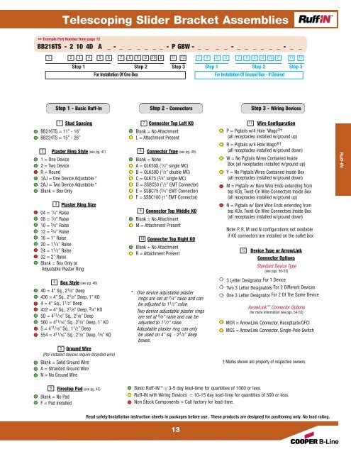
Telescoping Slider Bracket Assemblies<br />
•• Example Part Number from page 12<br />
BB216TS -210 4D A _ - _ _ _ _ _ _ -PGBW - _ _ _ _ - _ _ _ _ _ _ - _ _<br />
1 2 3 4 5<br />
6 7 8 9 8 10 8 11 12 2 4 5 6 7 8 9 8 10 8 11 12<br />
Step 1 Step 2 Step 3<br />
Step 1 - Basic Ruff-In<br />
1<br />
Stud Spacing<br />
BB216TS = 11” - 18”<br />
BB224TS = 15” - 26”<br />
2 Plaster Ring Style (see pg. 47)<br />
1 = One Device<br />
2 = Two Device<br />
R = Round<br />
1AJ = One Device Adjustable *<br />
2AJ = Two Device Adjustable *<br />
Blank = Box Only<br />
Plaster Ring Size<br />
04 = 1 /4” Raise<br />
08 = 1 /2” Raise<br />
10 = 5 /8” Raise<br />
12 = 3 /4” Raise<br />
16 = 1” Raise<br />
20 = 11 /4” Raise<br />
24 = 11 3<br />
/2” Raise<br />
32 = 2” Raise<br />
Blank = Box Only or<br />
Adjustable Plaster Ring<br />
Box Style (see pg. 48)<br />
4D = 4” Sq., 21 /8” Deep<br />
436 = 4” Sq., 21 /8” Deep, 1” KO<br />
4 = 4” Sq., 11 /2” Deep<br />
432 = 4” Sq., 21 /8” Deep, 3 /4” KO<br />
5D = 411 /16” Sq., 21 /8” Deep<br />
560 = 411 /16” Sq., 21 /8” Deep, 1” KO<br />
5 = 411 /16” Sq., 11 /2” Deep<br />
554 = 411 /16” Sq., 21 /8” Deep, 3 4<br />
/4” KO<br />
5 Ground Wire<br />
(Pre-installed devices require stranded wire)<br />
Blank = Solid Ground Wire<br />
A = Stranded Ground Wire<br />
N = No Ground Wire<br />
6 Firestop Pad (see pg. 45)<br />
Blank = No Pad<br />
F = Pad Installed<br />
For Installation Of One Box For Installation Of Second Box - If Desired<br />
Step 2 - Connectors<br />
7 Connector Top Left KO<br />
Blank = No Attachment<br />
L = Attachment Present<br />
Connector Type (see pg. 49)<br />
Blank = None<br />
A = QLK50S ( 1 /2” single MC)<br />
B = QLK50D ( 1 /2” double MC)<br />
C = QLK75 ( 3 /4” single MC)<br />
D = SSBC50 ( 1 /2” EMT Connector)<br />
E = SSBC75 ( 3 8<br />
/4” EMT Connector)<br />
F = SSBC100 (1” EMT Connector)<br />
9 Connector Top Middle KO<br />
Blank = No Attachment<br />
M = Attachment Present<br />
10 Connector Top Right KO<br />
Blank = No Attachment<br />
R = Attachment Present<br />
* One device adjustable plaster<br />
rings are set at 3 /4” raise and can<br />
be adjusted to 1 1 /2” raise.<br />
Two device adjustable plaster rings<br />
are set at 5 /8” raise and can be<br />
adjusted to 1 1 /2” raise.<br />
Adjustable plaster ring can only<br />
be used on 4” sq. - 2 1 /8” deep<br />
boxes.<br />
Read safety/installation instruction sheets in packages before use. These products are designed for positioning only. No load rating.<br />
13<br />
Step 1 Step 2 Step 3<br />
Step 3 - Wiring Devices<br />
Wire Configuration<br />
P = Pigtails w/4 Hole 1Wago ®†<br />
(all receptacles installed w/ground up)<br />
R = Pigtails w/4 Hole Wago ®†<br />
11<br />
(all receptacles installed w/ground down)<br />
W = No Pigtails Wires Contained Inside<br />
Box (all receptacles installed w/ground up)<br />
Y = No Pigtails Wires Contained Inside Box<br />
(all receptacles installed w/ground down)<br />
M = Pigtails w/ Bare Wire Ends extending from<br />
top KOs, Twist-On Wire Connectors Inside Box<br />
(all receptacles installed w/ground up)<br />
N = Pigtails w/ Bare Wire Ends extending from<br />
top KOs, Twist-On Wire Connectors Inside Box<br />
(all receptacles installed w/ground down)<br />
Note: P, R, M and N configurations not available<br />
if KO connectors are installed on the outlet box<br />
12<br />
Device Type or ArrowLink<br />
Connector Options<br />
Standard Device Type<br />
(see pgs. 50-53)<br />
3 Letter Designator For 1 Device<br />
Two 3 Letter Designators For 2 Different Devices<br />
One 3 Letter Designator For 2 Of The Same Device<br />
ArrowLink Connector Options<br />
(for more information see pgs. 54-55)<br />
MCR = ArrowLink Connector, Receptacle/GFCI<br />
MCS = ArrowLink Connector, Single-Pole Switch<br />
† Marks shown are property of respective owners.<br />
Basic Ruff-IN = 3-5 day lead-time for quantities of 1000 or less.<br />
Ruff-IN with Wiring Devices = 10-15 day lead-time for quantities of 500 or less.<br />
Non Stock Components = Call factory for lead-time.<br />
Ruff-IN