Download Entire Catalog - Cooper Industries
Download Entire Catalog - Cooper Industries
Download Entire Catalog - Cooper Industries

You also want an ePaper? Increase the reach of your titles
YUMPU automatically turns print PDFs into web optimized ePapers that Google loves.
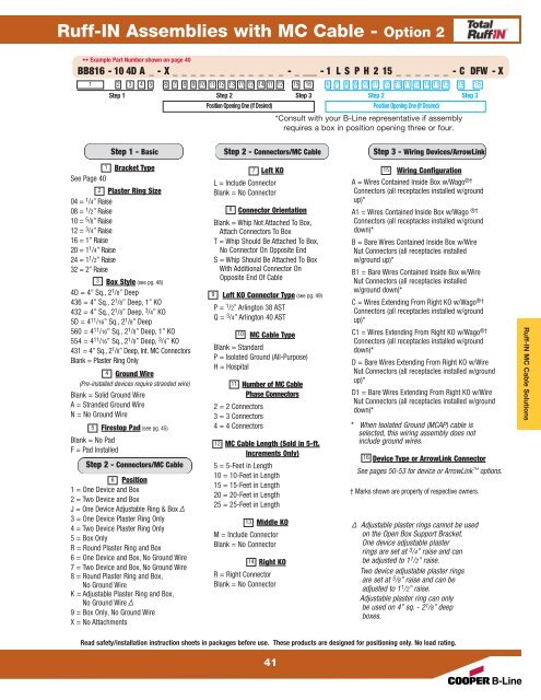
Ruff-IN Assemblies with MC Cable - Option 2<br />
•• Example Part Number shown on page 40<br />
BB816 - 10 4D A_-X____________-____ -1 L S P H 2 15 _ _ _ _ _ _ - C DFW - X<br />
1 2 3 4 5 6 7 8 9 10 11 12 13 11 12 14 11 12 15 16 6 7 8 9 10 11 12 13 11 12 14 11 12 15 16<br />
Step 1 Step 2 Step 3<br />
Step 2 Step 3<br />
Position Opening One (If Desired)<br />
Position Opening One (If Desired)<br />
*Consult with your B-Line representative if assembly<br />
requires a box in position opening three or four.<br />
Step 1 - Basic<br />
Bracket Type<br />
See Page 40<br />
Plaster Ring Size<br />
04 = 1 /4” Raise<br />
08 = 1 /2” Raise<br />
10 = 5 /8” Raise<br />
12 = 3 /4” Raise<br />
16 = 1” Raise<br />
20 = 11 /4” Raise<br />
24 = 11 /2” Raise<br />
32 = 2” Raise<br />
Box Style (see pg. 48)<br />
4D = 4” Sq., 21 /8” Deep<br />
436 = 4” Sq., 21 /8” Deep, 1” KO<br />
432 = 4” Sq., 21 /8” Deep, 3 /4” KO<br />
5D = 411 /16” Sq., 21 /8” Deep<br />
560 = 411 /16” Sq., 21 /8” Deep, 1” KO<br />
554 = 411 /16” Sq., 21 /8” Deep, 3 /4” KO<br />
431 = 4” Sq., 21 1<br />
2<br />
3<br />
/8” Deep, Int. MC Connectors<br />
Blank = Plaster Ring Only<br />
4 Ground Wire<br />
(Pre-installed devices require stranded wire)<br />
Blank = Solid Ground Wire<br />
A = Stranded Ground Wire<br />
N = No Ground Wire<br />
5 Firestop Pad (see pg. 45)<br />
Blank = No Pad<br />
F = Pad Installed<br />
Step 2 - Connectors/MC Cable<br />
6 Position<br />
1 = One Device and Box<br />
2 = Two Device and Box<br />
J = One Device Adjustable Ring & Box ∆<br />
3 = One Device Plaster Ring Only<br />
4 = Two Device Plaster Ring Only<br />
5 = Box Only<br />
R = Round Plaster Ring and Box<br />
6 = One Device and Box, No Ground Wire<br />
7 = Two Device and Box, No Ground Wire<br />
8 = Round Plaster Ring and Box,<br />
No Ground Wire<br />
K = Adjustable Plaster Ring and Box,<br />
No Ground Wire ∆<br />
9 = Box Only, No Ground Wire<br />
X = No Attachments<br />
Step 2 - Connectors/MC Cable<br />
7 Left KO<br />
L = Include Connector<br />
Blank = No Connector<br />
8 Connector Orientation<br />
Blank = Whip Not Attached To Box,<br />
Attach Connectors To Box<br />
T = Whip Should Be Attached To Box,<br />
No Connector On Opposite End<br />
S = Whip Should Be Attached To Box<br />
With Additional Connector On<br />
Opposite End Of Cable<br />
Left KO Connector Type (see pg. 49)<br />
P = 1 /2” Arlington 38 AST<br />
Q = 3 9<br />
/4” Arlington 40 AST<br />
10 MC Cable Type<br />
Blank = Standard<br />
P = Isolated Ground (All-Purpose)<br />
H = Hospital<br />
11 Number of MC Cable<br />
Phase Connectors<br />
2 = 2 Connectors<br />
3 = 3 Connectors<br />
4 = 4 Connectors<br />
12 MC Cable Length (Sold in 5-ft.<br />
Increments Only)<br />
5 = 5-Feet in Length<br />
10 = 10-Feet in Length<br />
15 = 15-Feet in Length<br />
20 = 20-Feet in Length<br />
25 = 25-Feet in Length<br />
13 Middle KO<br />
M = Include Connector<br />
Blank = No Connector<br />
14 Right KO<br />
R = Right Connector<br />
Blank = No Connector<br />
Read safety/installation instruction sheets in packages before use. These products are designed for positioning only. No load rating.<br />
41<br />
Step 3 - Wiring Devices/ArrowLink<br />
Wiring Configuration<br />
A = Wires Contained Inside Box w/Wago ®†<br />
Connectors (all receptacles installed w/ground<br />
up)*<br />
A1 = Wires Contained Inside Box w/Wago ®†<br />
Connectors (all receptacles installed w/ground<br />
down)*<br />
B = Bare Wires Contained Inside Box w/Wire<br />
Nut Connectors (all receptacles installed<br />
w/ground up)*<br />
B1 = Bare Wires Contained Inside Box w/Wire<br />
Nut Connectors (all receptacles installed<br />
w/ground down)*<br />
C = Wires Extending From Right KO w/Wago ®†<br />
Connectors (all receptacles installed w/ground<br />
up)*<br />
C1 = Wires Extending From Right KO w/Wago ®†<br />
15<br />
Connectors (all receptacles installed w/ground<br />
down)*<br />
D = Bare Wires Extending From Right KO w/Wire<br />
Nut Connectors (all receptacles installed w/ground<br />
up)*<br />
D1 = Bare Wires Extending From Right KO w/Wire<br />
Nut Connectors (all receptacles installed w/ground<br />
down)*<br />
* When Isolated Ground (MCAP) cable is<br />
selected, this wiring assembly does not<br />
include ground wires.<br />
Device Type or ArrowLink Connector<br />
See pages 50-53 for device or ArrowLink 16<br />
options.<br />
† Marks shown are property of respective owners.<br />
∆ Adjustable plaster rings cannot be used<br />
on the Open Box Support Bracket.<br />
One device adjustable plaster<br />
rings are set at 3 /4” raise and can<br />
be adjusted to 1 1 /2” raise.<br />
Two device adjustable plaster rings<br />
are set at 5 /8” raise and can be<br />
adjusted to 1 1 /2” raise.<br />
Adjustable plaster ring can only<br />
be used on 4” sq. - 2 1 /8” deep<br />
boxes.<br />
Ruff-IN MC Cable Solutions