Series V-316 - Versa Valves
Series V-316 - Versa Valves
Series V-316 - Versa Valves

You also want an ePaper? Increase the reach of your titles
YUMPU automatically turns print PDFs into web optimized ePapers that Google loves.
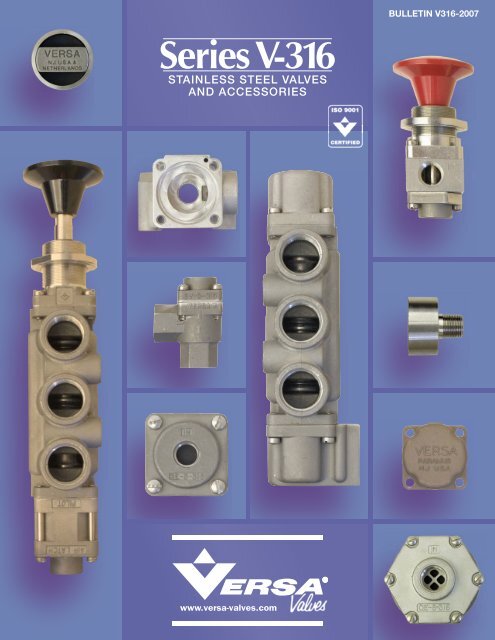
<strong>Series</strong> V-<strong>316</strong><br />
STAINLESS STEEL VALVES<br />
AND ACCESSORIES<br />
www.versa-valves.com<br />
BULLETIN V<strong>316</strong>-2007
MODULAR CONCEPT<br />
Manual Actuator<br />
The V-<strong>316</strong> Valve <strong>Series</strong> provides a full range of control valves suited to the<br />
most demanding of applications. Ruggedly constructed, both internally and<br />
externally, of stainless steel, these valves are able to withstand the physical<br />
abuse of corrosive environments and controlled media.<br />
A modular design concept utilizing three basic sub-assemblies: a Body<br />
Assembly and two Actuator Assemblies (active or passive), simplifi es circuit<br />
planning while affording almost unlimited combination possibilities.<br />
Port sizes are 1/4 NPT, 3/8 NPT and 1/2 NPT in three-way (3/2, 3/3), and<br />
four-way (5/2 and 5/3) styles.<br />
‘A’-181DE<br />
Sub-Assembly Nr.: CA-4302-65-<strong>316</strong>-181DE<br />
Spring Return Actuator<br />
‘S’<br />
Sub-Assembly Nr.: SA-4302-65-<strong>316</strong><br />
Actuation types include manual (hand lever, palm<br />
button, latching detent & manual reset), pilot (pressure<br />
pilot, diaphragm pilot, “air-latch” pilot), and solenoid-pilot<br />
(including several approved hazardous service types).<br />
Body Assembly<br />
‘4522’<br />
Sub-Assembly Nr.: SA-4522-71-<strong>316</strong><br />
Other functions can be easily<br />
accomplished as shown with these<br />
Pilot and Spring Return actuators.<br />
This Bulletin only gives the Actuator Sub-Assemblies and Body Sub-Assemblies.<br />
This gives the design engineer maximum versatility as these modules can be<br />
combined to complete valves with functions as needed.<br />
2.1<br />
<strong>Versa</strong> exercises diligence to assure that in formation<br />
contained in this catalog is correct, but does not<br />
accept responsibility for any errors or omissions. <strong>Versa</strong><br />
also reserves the right to change or delete data or<br />
products at any time without prior notifi cation. To be<br />
sure the data you require is correct, consult factory.<br />
VAG-4522-<strong>316</strong>-181DE-XX-(specify voltage)<br />
Solenoid-Pilot Actuator<br />
‘G’-XX<br />
Sub-Assembly Nr.:<br />
SA-4322-84-<strong>316</strong>-XX (specify voltage)<br />
Pilot Actuator<br />
‘P’<br />
Sub-Assembly Nr.: SA-4302-64-<strong>316</strong>
TECHNICAL DATA<br />
MATERIALS: Metal Parts: <strong>316</strong> stainless steel (except solenoid parts, ask factory)<br />
conforms to NACE standard MR-01-75.<br />
Hand Knob: plastic<br />
Seals: FKM (Fluorocarbon) is standard. Exceptions: diaphragm-pilot seal is NBR (Buna N) or with suffi x -31<br />
Tefl on coated Buna N; other seal materials are available. See ‘TEMPERATURES/SEALS’ below.<br />
PRESSURES: Valve type Pneumatic*<br />
VALVE BODY (inlet/system)<br />
Manual or Pilot — Standard Seals<br />
Single Solenoid EXPilot (2-position) — Standard Seals<br />
Double Solenoid EXPilot (2-position) — Standard Seals<br />
Double Solenoid EXPilot (3-position) — Standard Seals<br />
Single Solenoid INPilot (2-position) — Standard Seals<br />
Double Solenoid INPilot (2-position) — Standard Seals<br />
Double Solenoid INPilot (3-position) — Standard Seals<br />
PILOT (signal)<br />
Some restrictions concerning maximum pressures may apply.<br />
See specifi c actuator.<br />
Pilot (2-position “VSP” or 3-position “VJJ”)<br />
Pilot (2-position “VPP”)<br />
Diaphragm (2-position “VSW” or 3-position “VYY”)<br />
Diaphragm (2-position “VSW” or 3-position “VYY”) w/Suffi x -31<br />
Diaphragm (2-position VWW”)<br />
Diaphragm (2-position “VWW”) w/Suffi x -31<br />
Solenoid EXPilot (2-position “VSG” or 3-position “VXX”)<br />
Solenoid EXPilot (2 position (VGG”)<br />
3.1<br />
psi<br />
bar<br />
(Mpa = bar )<br />
10<br />
Vacuum to 200 Vacuum to 14<br />
40 to 175<br />
20 to 175<br />
40 to 175<br />
40 to 200<br />
20 to 200<br />
10 to 50<br />
10 to 200<br />
5 to 50<br />
5 to 200<br />
40 to 175<br />
20 to 175<br />
2.8 to 12<br />
1.4 to 12<br />
2.8 to 12<br />
2.8 to 14<br />
1.4 to 14<br />
0.7 to 3.4<br />
0.7 to 14<br />
0.34 to 3.4<br />
0.34 to 14<br />
2.8 to 12<br />
1.4 to 12<br />
Notes: — When application involves temperatures below freezing or when shifting intervals are relatively long, it is<br />
recommended that suffi x -S be specifi ed for valves with spring actuation. Minimum pilot pressure must be increased<br />
by 40%.<br />
Notes: — The following suffi xes include the use of suffi x -S in all cases: -181AAE, -181CE, -181DE, -3358AE, -3358E.<br />
*Consult factory for hydraulic service.<br />
TEMPERATURES/SEALS: The table below lists suggested suffi x options for various temperature ranges and/or<br />
types of service. For temperatures or conditions not listed, consult factory.<br />
Type of Service<br />
Temperature Range<br />
Intermittent Duty Service Continuous Duty Service<br />
(Medium/Ambient<br />
Temperature)<br />
AC or DC AC DC<br />
Coil Solenoid Plunger Coil Solenoid Plunger Coil Solenoid Plunger<br />
150ºF to 200ºF<br />
(65ºC) (95ºC)<br />
120ºF to 150ºF<br />
(50ºC) (65ºC)<br />
-10ºF to 120ºF<br />
(-23ºC) (50ºC)<br />
Suffi x<br />
-HT<br />
FLOW CALCULATION:<br />
FLOW:<br />
Suffi x -3 (may be<br />
inclusive in other suffi x<br />
options as it is in -HT)<br />
Standard Suffi x -3 (may be<br />
inclusive in other suffi x<br />
options)<br />
Suffi x<br />
-HT<br />
Suffi x -3 (may be<br />
inclusive in other suffi x<br />
options as it is in -HT)<br />
Standard Suffi x -3 (may be<br />
inclusive in other suffi x<br />
options)<br />
Standard Standard Standard Suffi x -3 (may be<br />
inclusive in other suffi x<br />
options)<br />
Air Flow = f (p1-p2)(p2) (T)(SG)<br />
English Metric<br />
Air fl ow SCFM Nm3 /h<br />
f = Conversion factor 22.5 × Cv 30.8 × Kv<br />
p1 = Upstream pressure<br />
p1 - p2 < 0.5 × p2<br />
p2 = Downstream pressure<br />
psi absolute bar absolute<br />
T = Temperature upstream absolute 460º + Fº 273º + Cº<br />
SG = Specifi c gravity<br />
Note: 0.59 SCFM = 1 Nm<br />
1.0 1.0<br />
3 /h<br />
14.5 psi = 1 bar<br />
Port Size of Valve Body<br />
For details see page 8.1 through 8.6<br />
1/4 NPT<br />
3/8 NPT<br />
1/2 NPT<br />
Flow Diameter<br />
inch mm<br />
3/8 9.5<br />
3/8 9.5<br />
5/8 16.0<br />
Flow Factor<br />
Cv Kv<br />
1.8 26<br />
2.0 29<br />
5.5 80<br />
Suffi x<br />
-HT<br />
Suffi x<br />
-HT<br />
Suffi x -3 (may be<br />
inclusive in other suffi x<br />
options as it is in -HT)<br />
Suffi x -3 (may be<br />
inclusive in other suffi x<br />
options as it is in -HT)<br />
Standard Suffi x -3 (may be<br />
inclusive in other suffi x<br />
options)
TECHNICAL DATA<br />
ELECTRICAL:<br />
Solenoid-Pilot actuated V<strong>316</strong> valves are available with a variety of different solenoids for both nonhazardous<br />
and hazardous locations. Basic details of these actuators are listed below. Dimensions, product numbers, and<br />
other details may be found on pages 5.1 through 5.6. For additional data consult factory.<br />
NON HAZARDOUS LOCATION SOLENOIDS<br />
Suffi x<br />
Identifi cation<br />
Protection<br />
Classifi cation<br />
Area Classifi cation<br />
and (Gas Grouping)<br />
3.2<br />
Certifi cation-<br />
(Conformance)<br />
-U General Purpose Indoor & Outdoor CSA NEMA 1, 2, 3<br />
-HC -U General Purpose Indoor & Outdoor CSA NEMA 4;<br />
IP65 per IEC 529<br />
HAZARDOUS LOCATION SOLENOIDS<br />
Suffi x<br />
Identifi cation<br />
-XX<br />
Page 5.3<br />
-LB-XX<br />
Page 5.4<br />
-XN<br />
Page 5.3<br />
-LB-XN<br />
Page 5.4<br />
-XDAS<br />
or<br />
-XDAT<br />
Page 5.3<br />
-XMAA<br />
or<br />
-XMAE<br />
or<br />
-XMAF<br />
or<br />
-XMAG<br />
Page 5.5<br />
-XMFA<br />
or<br />
-XMFE<br />
or<br />
-XMFF<br />
or<br />
-XMFG<br />
Page 5.5<br />
-HC-XISC<br />
-HCC-XISC<br />
Page 5.6<br />
-HC-XISX6<br />
-HCC-XISX6<br />
Page 5.6<br />
-XIFA<br />
or<br />
-XIFE<br />
or<br />
-XIFF<br />
Page 5.6<br />
Protection<br />
Classifi cation<br />
Area Classifi cation<br />
and (Gas Grouping)<br />
Hazardous Locations Class I, Division 2 (A & B)<br />
Class I, Division 1 (C & D)<br />
Class II, Division 1 (E, F, & G)<br />
Hazardous Locations Class I, Division 2 (A & B)<br />
Class I, Division 1 (C & D)<br />
Class II, Division 1 (E, F, & G)<br />
(d) Flameproof Zones 1 and 2<br />
(IIB+H2) Category 2G<br />
T4<br />
(d) Flameproof Zones 1 and 2<br />
(IIB+H2) Category 2G<br />
T6<br />
(d) Flameproof Zones 1 and 2<br />
(IIC) Category 2G<br />
(m) Encapsulation<br />
(e) Increased Safety<br />
(m) Encapsulation<br />
(e) Increased Safety<br />
Zones 1 and 2<br />
(II) Category 2G<br />
Zones 1 and 2<br />
(II) Category 2G<br />
Hazardous Locations Class I,<br />
Groups (A, B, C & D)<br />
Class II, Groups (E, F & G)<br />
Class III, Division 1<br />
(ia) Intrinsic Safe Zones 0, 1 and 2<br />
(IIC) Category 1G<br />
T6<br />
(ib) Intrinsic Safe Zones 1 and 2<br />
(IIB) Category 1G<br />
UL<br />
CSA<br />
UL<br />
CSA<br />
Certifi cation-<br />
(Conformance)<br />
ATEX IP66<br />
ATEX IP66<br />
NEMA 7 & 9<br />
NEMA 7 & 9<br />
ATEX IP66 and IP67<br />
ATEX IP66 and IP67<br />
ATEX IP66 and IP67<br />
Factory Mutual<br />
CSA<br />
NEMA 4<br />
ATEX IP65<br />
ATEX IP66 and IP67<br />
Ingress<br />
Protection<br />
Ingress<br />
Protection
PRODUCT NUMBER COIL CODES: Complete product numbers require, when<br />
applicable, a coil code that represents the desired coil current type, frequency<br />
and voltage. The coil code takes the form shown below, with ratings and voltage<br />
substituted as required.<br />
Rating Code<br />
A = 60Hz frequency<br />
D = Direct Current (DC)<br />
E = 50Hz frequency<br />
Voltage<br />
(Power)<br />
All usual 50 Hz & 60 Hz AC (6W)<br />
All usual DC (7W)<br />
24V60, 120V60, 240V60 (8.5W)<br />
24V50, 110V50, 220V50 (8.5W)<br />
12VDC, 24VDC, 48VDC (10.5W)<br />
Voltage<br />
(Power)<br />
All usual 50 Hz & 60 Hz AC (5.6W)<br />
All usual DC (7.2W)<br />
Voltage<br />
(Indicated by three digits:<br />
as example,<br />
24 volts = 024<br />
120 volts = 120.)<br />
12V60, 24V60, 48V60, 120V60, 240V60 (1.8W)<br />
6VDC, 12VDC, 24VDC, 48VDC (1.8W)<br />
All usual 50 Hz & 60 Hz AC (5.6W)<br />
All usual DC (7.2W)<br />
12V60, 24V60, 48V60, 120V60, 240V60 (1.8W)<br />
6VDC, 12VDC, 24VDC, 48VDC (1.8W)<br />
24V50, 230V50 (6W); 127V50 (10W)<br />
24V60, 120V60, 240V60 (10W)<br />
12VDC, 24VDC, 28VDC, 48VDC,<br />
110VDC, 125VDC (10W)<br />
24VDC (4W)<br />
(Consult factory for other voltage options)<br />
24VDC<br />
(10W inrush, 2.6W holding)<br />
(Consult factory for other voltages)<br />
24VDC<br />
system voltage prior to barrier<br />
(1.6 watt max.)<br />
24VDC<br />
system voltage prior to barrier<br />
(1.6 watt max.)<br />
24VDC (0.8W)<br />
(Consult factory for other voltages)<br />
Electrical<br />
Characteristics Miscellaneous<br />
Class F epoxy molded coil (155ºC). Continuous duty<br />
2 leads 24” (60 cm).<br />
Class F epoxy molded coil (155ºC), with 3 spade<br />
terminals and mini DIN socket with PG9 cable gland.<br />
Continuous duty.<br />
Class F epoxy molded coil (155ºC).<br />
Continuous duty.<br />
3 leads 24” (60 cm).<br />
Class F epoxy molded coil (155ºC).<br />
Continuous duty.<br />
3 leads 24” (60 cm).<br />
Class F epoxy molded coil (155ºC).<br />
Continuous duty.<br />
3 leads 24” (60 cm).<br />
Class F epoxy molded coil (155ºC).<br />
Continuous duty.<br />
3 leads 24” (60 cm).<br />
Class F epoxy molded coil (155ºC).<br />
Continuous duty.<br />
Continuous duty. Coil & Rectifi er,<br />
including surge suppression,<br />
potted within housing.<br />
3.3<br />
Steel cover with 1/2 NPT conduit entry.<br />
Page 5.1<br />
Page 5.1<br />
Electrical<br />
Characteristics Miscellaneous<br />
Continuous duty. Coil & Power Controller potted within<br />
housing.<br />
Class F epoxy molded coil (155ºC).<br />
Continuous duty.<br />
Class F epoxy molded coil (155ºC).<br />
Continuous duty.<br />
Continuous duty. Coil and power controller potted within<br />
housing.<br />
Steel chromate coated coil housing with 1/2 NPT conduit entry.<br />
For stainless steel (182FM) coil housing add: (-ST)<br />
Steel chromate coated coil housing<br />
with 1/2 NPT conduit entry.<br />
For stainless steel (182FM ) coil housing add: (-ST)<br />
Maximum pilot pressure 120 psi (8 bar).<br />
1.8W nominal power.<br />
Steel chromate coated coil housing<br />
with M20 x 1.5 conduit entry.<br />
Ground terminal on cover.<br />
For stainless steel (182FM) coil housing add: (-ST)<br />
Steel chromate coated coil housing<br />
with M20 x 1.5 conduit entry.<br />
Ground terminal on cover.<br />
For stainless steel (182FM) coil housing add: (-ST)<br />
Maximum pilot pressure 120 psi (8 bar)<br />
1.8W nominal power.<br />
Stainless steel coil housing with internal Junction Box. Internal<br />
and external ground screw.<br />
M20 x 1.5 conduit entry: (-XDAS)<br />
1/2 NPT conduit entry: (-XDAT)<br />
Thick wall epoxy coil housing with integral<br />
junction box. Internal ground terminal.<br />
M20 x 1.5 conduit entry: (-XMAA)<br />
Cable gland for 6-12 mm ø cable: (-XMAE)<br />
1/2 NPT conduit entry with adapter: (-XMAF)<br />
Cable gland for 9-16 mm ø cable: (-XMAG)<br />
Thick wall epoxy coil housing with integral<br />
junction box. Internal ground terminal.<br />
M20 x 1.5 conduit entry: (-XMFA)<br />
Cable gland for 6-12 mm ø cable: (-XMFE)<br />
1/2 NPT conduit entry with adapter: (-XMFF)<br />
Cable gland for 9-16 mm ø cable: (-XMFG)<br />
Requires the use of an approved barrier or isolator.<br />
Maximum operating system voltage before barrier 28VDC.<br />
Maximum pilot pressure 115 psi (8 bar).<br />
3 spade terminals & DIN connector with PG9<br />
cable gland: (-HC)<br />
1/2 NPT conduit entry: (-HCC)<br />
Requires the use of an approved barrier or isolator.<br />
Maximum operating system voltage before barrier 28VDC.<br />
Maximum pilot pressure 115 psi (8 bar).<br />
3 spade terminals & DIN connector with PG9<br />
cable gland: (-HC)<br />
1/2 NPT conduit entry: (-HCC)<br />
Requires the use of an approved safety barrier or isolator.<br />
Thick wall epoxy coil housing and integral<br />
junction box. Internal ground terminal.<br />
M20 x 1.5 conduit entry: (-XIFA)<br />
Cable gland for 6-12 mm ø cable: (-XIFE)<br />
1/2 NPT conduit entry with adapter: (-XIFF)
SELECTOR CHART & PRODUCT NUMBERING<br />
Each letter and digit in the product number of a <strong>Versa</strong> Valve has a signifi cant meaning, as explained below.<br />
Letters or numbers shown in black in the example below do not change.<br />
V S P 3 3 0 1 <strong>316</strong> Suffi x<br />
BODY DETAILS<br />
Spool<br />
Details<br />
(fl ow pattern*)<br />
Port Size Type<br />
of<br />
Body<br />
ACTUATING DEVICES Function<br />
At left end of At right end of (also see Spool<br />
valve<br />
valve<br />
Details)<br />
when looking at inlet port of body*<br />
A Combination - or Special 3*<br />
Actuator<br />
Three-Way<br />
3/2 or 3/3<br />
Valve<br />
<strong>Series</strong><br />
Suffi x Detail<br />
numbers indicate<br />
modifi cations or<br />
variations of the<br />
basic Valve. When<br />
specifying, simply<br />
add the Suffi x<br />
Details required<br />
in alphabetical<br />
and numerical<br />
following order.<br />
‘<strong>316</strong>’ indicates<br />
that the basic<br />
construction<br />
material for valve<br />
parts is AISI <strong>316</strong><br />
Stainless Steel<br />
(Conforms to<br />
NACE Standard<br />
MR-01-75)<br />
Three-Way<br />
3/2 <strong>Valves</strong><br />
Sideported<br />
EXPilot<br />
0 Body with<br />
threaded<br />
side-ports<br />
(for Manual,<br />
Pilot and EX-<br />
Pilot solenoid<br />
actuated<br />
valves)<br />
Sideported<br />
INPilot<br />
2 Body with<br />
threaded<br />
side-ports<br />
and internal<br />
drilling to<br />
supply inlet<br />
pressure to<br />
INPilot act. of<br />
Solenoid-pilot<br />
1/4 NPT<br />
3<br />
1<br />
3/8 NPT<br />
4<br />
Norm. Closed<br />
1/2 NPT<br />
5<br />
4<br />
Spring centering<br />
(for 3 position manually<br />
operated valves)<br />
B<br />
2<br />
Four-Way<br />
5/2 or 5/3<br />
Solenoid-pilot<br />
G<br />
Norm. Open<br />
7<br />
2 Two Outlet<br />
(See Function<br />
column for<br />
fl ow)<br />
Hand Button<br />
(for panel mounting)<br />
I<br />
Two Outlet<br />
(Diverter)<br />
3/2 or 3/3<br />
<strong>Series</strong> V-<strong>316</strong><br />
<strong>Valves</strong><br />
Pneumatic<br />
Service<br />
(Nominal<br />
Pressure Range<br />
Vacuum to 200<br />
psi (14 bar).<br />
Some restrictions<br />
apply.<br />
See specifi c<br />
actuators.)<br />
In this bulletin<br />
many Suffi x<br />
Details are<br />
described. For<br />
more: see Suffi x<br />
Detail Product<br />
Bulletin, or consult<br />
factory.<br />
Pilot-Spring Centering<br />
2 Two Inlet<br />
(See Function<br />
column for<br />
fl ow)<br />
8<br />
Hand-Lever<br />
Two Inlet<br />
(Selector)<br />
3/2 or 3/3<br />
Non-return end-cap<br />
Pressure-Pilot<br />
Three-Way<br />
3/3 <strong>Valves</strong><br />
J<br />
L<br />
N<br />
P<br />
R<br />
Coil voltages<br />
are indicated<br />
here. For specifi c<br />
voltage, use coil<br />
code number<br />
listed on page 3.3.<br />
*<br />
Two-Way may<br />
be accomplished<br />
by plugging the<br />
exhaust port of<br />
three-way valve<br />
bodies<br />
Reverse Spring Return<br />
(spring pulls valve spool)<br />
3.4<br />
3<br />
4<br />
Spring Return<br />
(spring pushes<br />
valve spool)<br />
S<br />
For 3/3<br />
Two-inlet or<br />
Two-outlet<br />
see pg. 8.3<br />
3-Position Detent<br />
(For 3 position manually<br />
operated valves)<br />
U<br />
Diaphragm-Pilot<br />
(low pressure-pilot)<br />
W<br />
Four-Way<br />
5/2 <strong>Valves</strong><br />
Solenoid-Pilot<br />
Spring Centering<br />
(for 3 position solenoid<br />
2<br />
pilot valves)<br />
Four-Way<br />
5/3 <strong>Valves</strong><br />
Y Diaphragm-Pilot<br />
Spring Centering<br />
(for 3 position<br />
3<br />
Diaphragm-Pilot valves)<br />
4<br />
Z 2-Position Detent<br />
(for 2-position manually<br />
*Left and Right Flow<br />
Diagrams indicate<br />
operated valves)<br />
2-position valve.<br />
*3-way NC function requires actuator device<br />
Center Flow Diagram<br />
shows 3-position. For<br />
on right. 3-way NO function requires actuator<br />
other Center Flow<br />
device on left.<br />
patterns, see pages<br />
8.1 thru 8.6<br />
VERSA <strong>Series</strong> V-<strong>316</strong> <strong>Valves</strong> consist of three Sub-Assemblies: one Body-Assembly and two Actuator-Assemblies, mounted at the LH side and the RH side of the Body. All the Actuators<br />
can be mounted at either side, are fully interchangeable and can be combined to suit the function desired. See Pages 4.1 through 8.6 for those Sub-Assemblies.<br />
X
PILOT ACTUATORS*<br />
DIMENSIONS SHOWN IN INCH<br />
MM<br />
Symbol Designation<br />
In Product Number<br />
Prefi x Suffi x<br />
4.1<br />
Title and<br />
Sub-assembly Number<br />
(PRESSURE) PILOT<br />
P SA-4302-64-<strong>316</strong><br />
PULL TYPE (PRESSURE) PILOT<br />
A and -PTP CA-4302-64-<strong>316</strong>-PTP<br />
(PRESSURE) PILOT with Threaded<br />
Vent port<br />
P and -107E SA-4302-64-<strong>316</strong>-107E<br />
PUSH-PULL (PRESSURE) PILOT<br />
A and -PPP CA-4302-64-<strong>316</strong>-PPP<br />
(PRESSURE) PILOT-SPRING<br />
CENTERED<br />
(for 3 position pilot operated valves)<br />
J SA-4302-83-<strong>316</strong><br />
“AIR LATCH” (PRESSURE) PILOT<br />
‘hold function’ only<br />
A and -301E CA-4302-64-<strong>316</strong>-301E<br />
“AIR LATCH” (PRESSURE) PILOT-<br />
PULL TYPE<br />
‘hold function’ only<br />
A and -301RE CA-4302-64-<strong>316</strong>-301RE<br />
*For Pilot Pressure ranges see page 3.1
PILOT ACTUATORS*<br />
DIMENSIONS SHOWN IN INCH<br />
MM<br />
Symbol Designation<br />
In Product Number<br />
Prefi x Suffi x<br />
PILOT-COMBINATION ACTUATORS*<br />
DIMENSIONS SHOWN IN INCH<br />
MM<br />
4.2<br />
Title and<br />
Sub-assembly Number<br />
DIAPHRAGM PILOT<br />
(for 2 position diaphragm pilot operated valves)<br />
W SA-4302-87-<strong>316</strong><br />
For low pressure pilot signals<br />
DIAPHRAGM PILOT-<br />
SPRING CENTERED<br />
(for 3 position diaphragm pilot operated valves)<br />
Y For low pressure pilot signals<br />
SA-4302-88-<strong>316</strong><br />
NOTE: Diaphragm piston can be equipped with Tefl on coated<br />
Buna N “U” cup. Add suffi x “-31” to complete valve number or<br />
sub-assembly number.<br />
(PRESSURE) PILOT-TWO DETENT<br />
A and -150E CA-4302-64-<strong>316</strong>-150E<br />
(PRESSURE) PILOT-REVERSE<br />
SPRING RETURN<br />
A and -159E CA-4302-64-<strong>316</strong>-159E<br />
*For Pilot Pressure ranges see page 3.1
SOLENOID-PILOT ACTUATORS —<br />
24” Leads<br />
Third Wire Ground<br />
Supplied When<br />
Requested<br />
1/2 - 14 NPT<br />
Conduit Conn<br />
Manual Override<br />
(Suffix - ME)<br />
DIMENSIONS SHOWN IN INCH<br />
MM<br />
Height dimensions shown are for Nonhazardous solenoids.<br />
Dimension for Hazardous solenoids depend upon type of<br />
solenoid selected.<br />
Suffi x<br />
+options: -HT High Temperature Class H coil<br />
-H2 adapter with 1/8 NPT thread<br />
-L14 Dust Excluder Solenoid Nut<br />
-ME manual override<br />
-PC potted coil; NEMA 4/4X, IP65<br />
-243 wire leads with grommet type<br />
housing<br />
PG-9<br />
Cable Entry<br />
Mini DIN<br />
Connector<br />
Manual Override<br />
(Suffix - ME)<br />
2 Position<br />
(For 3 Position refer<br />
also to drawing at top of page)<br />
VERSA<br />
10-32 UNF<br />
Adapter Option<br />
1/8 NPT (Suffix - H2)<br />
125<br />
31.7<br />
1.62<br />
41.3<br />
2.54<br />
64.6<br />
1.48<br />
37.7<br />
10-32 UNF<br />
1.62<br />
41.3<br />
.57<br />
14.5<br />
3.00<br />
76.2<br />
.69<br />
17.5<br />
2 Position<br />
3 Position<br />
2.11<br />
53.5<br />
.94<br />
23.9<br />
1.38<br />
35.1<br />
1/8 NPT Pilot Inlet Port<br />
(on EXPilot <strong>Valves</strong> only)<br />
Adapter Option<br />
1/8 NPT (Suffix - H2)<br />
.57<br />
14.5<br />
3.00<br />
76.2<br />
.69<br />
17.5<br />
3.62<br />
92.0<br />
.94<br />
23.9<br />
1.38<br />
35.1<br />
1/8 NPT Pilot Inlet Port<br />
(on EXPilot <strong>Valves</strong> only)<br />
Suffi x<br />
+options: -HT adapter with 1/8 NPT thread<br />
-L14 Dust Excluder Solenoid Nut<br />
-ME manual override<br />
5.1<br />
2 Position<br />
GENERAL SERVICE<br />
(NONHAZARDOUS SERVICE)<br />
Symbol Designation<br />
In Product Number<br />
Prefi x Suffi x<br />
Title and<br />
Sub-assembly Number<br />
SOLENOID PILOT<br />
(with threads for conduit connection)<br />
G and -U SA-4302-84-<strong>316</strong>-U-.+.-(**)<br />
(EXPilot type)<br />
G and -U SA-4322-84-<strong>316</strong>-U-.+.-(**)<br />
(INPilot type)<br />
3 Position<br />
— GENERAL SERVICE (NONHAZARDOUS SERVICE)<br />
3 Position<br />
— HAZARDOUS SERVICE<br />
Any of the solenoids shown on pages 5.3, 5.4, 5.5,<br />
and 5.6 can be used on this actuator.<br />
X and -.U.<br />
SOLENOID-PILOT<br />
SPRING CENTERING<br />
(for 3 posiition solenoid operated valves)<br />
Available for any of the solenoids and respective<br />
options shown on pages 5.1, 5.3,<br />
5.4, 5.5 and 5.6.<br />
SA-4302-85-<strong>316</strong>-.U.-.+.-(**)<br />
(EXPilot type)<br />
X and -.U. SA-4322-85-<strong>316</strong>-.U.-.+.-(**)<br />
(INPilot type)<br />
(**) Specify coil code on page 3.3, to complete number<br />
2 Position<br />
— GENERAL SERVICE (NONHAZARDOUS SERVICE)<br />
SOLENOID-PILOT<br />
(with DIN type connector-spade<br />
terminal coil)<br />
G and -HC-U SA-4302-84-<strong>316</strong>-HC-U-.+.-(**)<br />
(EXPilot type)<br />
G and -HC-U SA-4322-84-<strong>316</strong>-HC-U-.+.-(**)<br />
(INPilot type)<br />
3 Position<br />
(For 3 Position also refer to drawing at top of page)<br />
— GENERAL SERVICE (NONHAZARDOUS SERVICE)<br />
SOLENOID-PILOT<br />
SPRING CENTERING<br />
(with DIN type connector-spade<br />
terminal coil)<br />
X and -HC-U SA-4302-85-<strong>316</strong>-HC-U-.+.-(**)<br />
(EXPilot type)<br />
X and -HC-U SA-4322-85-<strong>316</strong>-HC-U-.+.-(**)<br />
(INPilot type)<br />
(**) Specify coil code on page 3.3, to complete number
SOLENOID-PILOT COMBINATION ACTUATORS —<br />
DIMENSIONS SHOWN IN INCH<br />
MM<br />
Any of the solenoids shown<br />
on pages 5.1, 5.3, 5.4, 5.5,<br />
and 5.6 can be used on this<br />
actuator<br />
Designation<br />
In Product Number<br />
Prefi x Suffi x<br />
REDUNDANT SOLENOID ACTUATOR —<br />
DIMENSIONS SHOWN IN INCH<br />
MM<br />
Designation<br />
In Product Number<br />
Prefi x Suffi x<br />
5.2<br />
Title and<br />
Sub-assembly Number<br />
Title and<br />
Sub-assembly Number<br />
2 Position<br />
GENERAL<br />
(NONHAZARDOUS)<br />
OR HAZARDOUS<br />
SERVICE<br />
SOLENOID-PILOT and<br />
‘REVERSE’ SPRING RETURN<br />
A and -138E-.?.- CA-4302-84-<strong>316</strong>-138E-.?.-.+.-(**)<br />
(EXPilot type)<br />
A and -138E-.?.- CA-4322-84-<strong>316</strong>-138E-.?.-.+.-(**)<br />
(INPilot type)<br />
SOLENOID-PILOT<br />
TWO DETENT<br />
A and -173E-.?.- CA-4302-84-<strong>316</strong>-173E-.?.-.+.-(**)<br />
(EXPilot type)<br />
A and -173E-.?.- CA-4322-84-<strong>316</strong>-173E-.?.-.+.-(**)<br />
(INPilot type)<br />
SOLENOID ‘AIR-LATCH’ PILOT<br />
‘hold function only’<br />
A and -301GE-.?.- CA-4302-84-<strong>316</strong>-301GE-.?.-.+.-(**)<br />
(EXPilot type)<br />
A and -301GE-.?.- CA-4322-84-<strong>316</strong>-301GE-.?.-.+.-(**)<br />
(INPilot type)<br />
? Specify suffi x on page 3.2, which solenoid operator is required.<br />
+ Specify Options<br />
(**) Specify coil code to complete number.<br />
2 Position<br />
GENERAL SERVICE (NONHAZARDOUS)<br />
OR HAZARDOUS SERVICE<br />
SOLENOID-PILOT and<br />
REDUNDANT SOLENOID-PILOT<br />
A and -RS-.?.- CA-4302-84-<strong>316</strong>-RS-.?.-.+.-(**)<br />
(EXPilot type)<br />
A and -RS-.?.- CA-4322-84-<strong>316</strong>-RS-.?.-.+.-(**)<br />
(INPilot type)<br />
? Specify suffi x on page 3.2, which solenoid operator is required.<br />
+ Specify Options<br />
(**) Specify coil code to complete number.
SOLENOID-PILOT ACTUATORS —<br />
24” Leads<br />
2 Wire w/Ground<br />
1/2 - 14 NPT (XDAT)<br />
M20 x 1.5 (XDAS)<br />
1/2 - 14 NPT (-XX)<br />
M20 x 1.5 (-XN)<br />
Elect Conn<br />
DIMENSIONS SHOWN IN INCH<br />
MM<br />
Manual Override<br />
(Suffix - ME )<br />
Earthen Ground for -XN<br />
2.2<br />
56.0<br />
3.35<br />
Ø<br />
85.0<br />
1.52<br />
38.5<br />
1.44<br />
Ø<br />
36.5<br />
1.62<br />
41.3<br />
VERSA<br />
PARAMUS NJ - SA<br />
APELDOORN<br />
THE NETHERLANDS<br />
1.37<br />
34.8<br />
Adapter Option<br />
1/8 NPT ( Suffix -- H2 )<br />
10-32 UNF<br />
.57<br />
14.5<br />
3.08<br />
78.3<br />
.69<br />
17.5<br />
1/8 NPT (Suffix - H2)<br />
1/4 NPT (Suffix - H)<br />
.59<br />
15.0<br />
.69<br />
17.5<br />
.61<br />
15.5<br />
2.26<br />
57.4<br />
.94<br />
23.9<br />
1.38<br />
35.1<br />
1/8 NPT Pilot Inlet Port<br />
( on EXPilot <strong>Valves</strong> only )<br />
1.38<br />
35.0<br />
1/8 NPT Pilot Inlet Port<br />
(on EX Pilot <strong>Valves</strong> only)<br />
5.3<br />
2 Position (for 3 Position also refer to Drawing at top of<br />
page 5.1)<br />
HAZARDOUS SERVICE<br />
Symbol Designation<br />
In Product Number<br />
Prefi x Suffi x<br />
Title and<br />
Sub-assembly Number<br />
SOLENOID-PILOT<br />
Hazardous Locations<br />
{-XX: UL listed & CSA approved for Hazardous<br />
Locations; Class I, Div 2 (A & B); Class I, Div 1<br />
(C & D); Class II, Div 1 (E, F & G).}<br />
(d) Flameproof<br />
{-XN: ATEX approved; Zones 1 and 2, (IIB + H2)<br />
Category 2G.}<br />
G and -XX SA-4302-84-<strong>316</strong>-XX-.+.-(**)<br />
G and -XN SA-4302-84-<strong>316</strong>-XN-.+.-(**)<br />
(EXPilot type)<br />
G and -XX SA-4322-84-<strong>316</strong>-XX-.+.-(**)<br />
G and -XN SA-4322-84-<strong>316</strong>-XN-.+.-(**)<br />
(INPilot type)<br />
Suffi x<br />
+options: -HT High Temperature Class H coil<br />
(For UL or CSA approved,<br />
consult factory)<br />
-H2 adapter with 1/8 NPT thread<br />
-L14 Dust Excluder Solenoid Nut<br />
-ME manual override<br />
-ST #182FM stainless steel coil housing<br />
-PC potted coil; NEMA 4/4X, IP65<br />
(**) Specify coil code on page 3.3, to complete number<br />
SOLENOID-PILOT<br />
(d) Flameproof<br />
{-XDAS or –XDAT; ATEX approved; Zones 1 and<br />
2, (IIC) Category 2G.}<br />
G and -XDA* SA-4302-84-<strong>316</strong>-XDA..*.-.+.-(**)<br />
(EXPilot type)<br />
G and -XDA* SA-4322-84-<strong>316</strong>-XDA..*.-.+.-(**)<br />
(INPilot type)<br />
*Specify identifi cation detail. Detail<br />
S: M20 x 1.5 conduit entry<br />
T: 1/2 NPT conduit entry<br />
Suffi x<br />
+options: -HT High Temperature Class H coil<br />
-H2 adapter with 1/8 NPT thread<br />
-H2 adapter with 1/4 NPT thread<br />
-303 Varistor for suppression purposes<br />
included<br />
(**) Specify coil code on page 3.3, to complete number
SOLENOID-PILOT ACTUATORS —<br />
DIMENSIONS SHOWN IN INCH<br />
MM<br />
NOTE: 2 position shown. Refer to Drawing page 5.1 for 3 position.<br />
Symbol<br />
Designation<br />
In Product Number<br />
Prefi x Suffi x<br />
5.4<br />
2 Position (for 3 Position also refer to Drawing at top of<br />
page 5.1)<br />
HAZARDOUS SERVICE<br />
SOLENOID-PILOT<br />
LOW-WATT TYPE-<br />
Nominal Power 1.8W<br />
Hazardous Locations<br />
{-LB-XX: UL listed & CSA approved for<br />
Hazardous Locations; Class I, Division 2<br />
(A & B); Class I, Division 1 (C & D); Class II,<br />
Division 1 (E, F & G).}<br />
(d) Flameproof<br />
{-LB-XN: ATEX approved; Zones 1 and 2,<br />
(IIB + H2) Category 2G.}<br />
Max pilot pressure 120 psi (8 bar); air only.<br />
Title and<br />
Sub-assembly Number<br />
G and -LB-XX SA-4302-84-<strong>316</strong>-LB-XX-.+.-(**)<br />
G and -LB-XN SA-4302-84-<strong>316</strong>-LB-XN-.+.-(**)<br />
(EXPilot type)<br />
G and -LB-XX SA-4322-84-<strong>316</strong>-LB-XX-.+.-(**)<br />
G and -LB-XN SA-4322-84-<strong>316</strong>-LB-XN-.+.-(**)<br />
(INPilot type)<br />
X and -LB-XX SA-4302-85-<strong>316</strong>-LB-XX-.+.-(**)<br />
X and -LB-XN SA-4302-85-<strong>316</strong>-LB-XN-.+.-(**)<br />
(EXPilot type)<br />
X and -LB-XX SA-4322-85-<strong>316</strong>-LB-XX-.+.-(**)<br />
X and -LB-XN SA-4322-85-<strong>316</strong>-LB-XN-.+.-(**)<br />
(INPilot type)<br />
Suffi x<br />
+options: -H2 Adapter with 1/8 NPT thread<br />
-L14 Dust Excluder Solenoid Nut<br />
-ME Manual Override<br />
-ST #182 FM stainless steel coil housing<br />
(**) Specify coil code on page 3.3, to complete number
SOLENOID-PILOT ACTUATORS —<br />
.75<br />
19.1<br />
Manual Override<br />
(Suffix -ME)<br />
.75<br />
19.1<br />
Manual Override<br />
(Suffix -ME)<br />
DIMENSIONS SHOWN IN INCH<br />
MM<br />
1.62<br />
41.3<br />
1.62<br />
41.3<br />
1/8 NPT (Suffix - H2)<br />
1/4 NPT (Suffix - H)<br />
•<br />
ADAPTER: .69<br />
1/2 NPT (-XMAF) 17.5<br />
CABLE GLAND<br />
(-XMAE & -XMAG)<br />
1/8 NPT (Suffix - H2)<br />
1/4 NPT (Suffix - H)<br />
•<br />
ADAPTER:<br />
1/2 NPT (-XMFF)<br />
CABLE GLAND<br />
(-XMFE & XMFG)<br />
(M20 X 1.5)<br />
(-XMAA)<br />
1.38<br />
35.1<br />
1/8 NPT Pilot Inlet Port<br />
(on EXPilot <strong>Valves</strong> only)<br />
(M20 X 1.5)<br />
(-XMFA)<br />
.69<br />
17.5<br />
RSA<br />
RSA USA<br />
RN NL<br />
RSA<br />
RSA USA<br />
RN NL<br />
.94<br />
23.9<br />
.94<br />
23.9<br />
1.38<br />
35.1<br />
1/8 NPT Pilot Inlet Port<br />
(on EXPilot <strong>Valves</strong> only)<br />
Symbol Designation<br />
In Product Number<br />
Prefi x Suffi x<br />
5.5<br />
2 Position (for 3 Position also refer to Drawing at top of<br />
page 5.1)<br />
HAZARDOUS SERVICE<br />
Title and<br />
Sub-assembly Number<br />
SOLENOID-PILOT<br />
(m) Encapsulation, (e) Increased Safety<br />
{-XMA*: ATEX approved; Zones 1 and 2,<br />
(II) Category 2G.}<br />
Max. pilot pressure 175 psi [12 bar]<br />
G and -XMA* SA-4302-84-<strong>316</strong>-XMA*-.+.-(**)<br />
(EXPilot type)<br />
G and -XMA* SA-4322-84-<strong>316</strong>-XMA*-.+.-(**)<br />
(INPilot type)<br />
*Specify identifi cation detail.<br />
Detail<br />
A: M20 x 1.5 conduit entry.<br />
E: Cable gland for 6-12mm ø cable<br />
F: 1/2 NPT conduit entry with adapter.<br />
G: Cable gland for 9-16 mm ø cable<br />
Suffi x<br />
+options: -H Adapter with 1/4 NPT thread<br />
-H2 Adapter with 1/8 NPT thread<br />
-L14 Dust Excluder Solenoid Nut<br />
(**) Specify coil code on page 3.3, to complete number.<br />
SOLENOID-PILOT<br />
(m) Encapsulation, (e) Increased Safety<br />
{-XMF*: ATEX approved; Zones 1 and 2,<br />
(II) Category 2G.}<br />
Max. pilot pressure 175 psi [12 bar ]<br />
G and -XMF* SA-4302-84-<strong>316</strong>-XMF*-.+.-D024<br />
(EXPilot type)<br />
G and -XMF* SA-4322-84-<strong>316</strong>-XMF*-.+.-D024<br />
(INPilot type)<br />
*Specify identifi cation detail.<br />
Detail<br />
A: M20 x 1.5 conduit entry.<br />
E: Cable gland for 6-12mm ø cable.<br />
F: 1/2 NPT conduit entry with adapter.<br />
G: Cable gland for 9-16mm ø cable.<br />
Suffi x<br />
+options: -H Adapter with 1/4 NPT thread<br />
-H2 Adapter with 1/8 NPT thread<br />
-L14 Dust Excluder Solenoid Nut
SOLENOID-PILOT ACTUATORS —<br />
DIMENSIONS SHOWN IN INCH<br />
MM<br />
PG-9<br />
Cable Entry -HC<br />
(1/2 NPT conduit<br />
entry -HCC)<br />
ISO Connector<br />
Manual Override<br />
(Suffix -ME)<br />
.75<br />
19.1<br />
Manual Override<br />
(Suffix -ME)<br />
1.62<br />
41.3<br />
Can be rotated<br />
through 360°<br />
1.69<br />
43.0<br />
•<br />
1.62<br />
41.3<br />
1/8 NPT (Suffix - H2)<br />
1/4 NPT (Suffix - H)<br />
•<br />
1/2 NPT<br />
(XIFF)<br />
CABLE<br />
GLAND<br />
(XIFE)<br />
.69<br />
17.5<br />
M5 Threaded<br />
EXH Port<br />
Torque setting for<br />
tightening nut at<br />
assembly is 12 lbf - in (1.4 Nm)<br />
2.82<br />
71.6<br />
.69<br />
17.5<br />
M20 X 1.5<br />
(XIFA)<br />
3.33<br />
84.6<br />
.94<br />
23.9<br />
RSA<br />
RSA USA<br />
RN NL<br />
1.38<br />
35.1<br />
Symbol Designation<br />
In Product Number<br />
Prefi x Suffi x<br />
1/8 NPT Pilot Inlet Port<br />
(on EXPilot <strong>Valves</strong> only)<br />
.94<br />
23.9<br />
1.38<br />
35.1<br />
1/8 NPT Pilot Inlet Port<br />
(on EXPilot <strong>Valves</strong> only)<br />
5.6<br />
2 Position (for 3 Position also refer to Drawing at top of<br />
page 5.1)<br />
HAZARDOUS SERVICE<br />
Title and<br />
Sub-assembly Number<br />
SOLENOID-PILOT<br />
Hazardous Locations<br />
{-HC-XISC or –HCC-XISC: Factory Mutual<br />
& CSA approved; Class I, Groups (A, B, C,<br />
& D); Class II, Groups (E, F, & G); Class III,<br />
Div. 1)}<br />
(ia) Intrinsic Safe<br />
{-HC-XISX6 or –HCC-XISX6: ATEX<br />
approved; Zones 0, 1 & 2; (IIC) Category<br />
1G}<br />
Approved Safety Barrier or isolator required.<br />
Max. pilot pressure 115 psi [8 bar].<br />
G and -*-XISC SA-4302-84-<strong>316</strong>-*-XISC-.+.-D024<br />
G and -*-XISX6 SA-4302-84-<strong>316</strong>-*-XISX6-.+.-D024<br />
(EXPilot type)<br />
G and -*-XISC SA-4322-84-<strong>316</strong>-*-XISC-.+.-D024<br />
G and -*-XISX6 SA-4322-84-<strong>316</strong>-*-XISX6-.+.-D024<br />
(INPilot type)<br />
*Specify identifi cation detail. Detail<br />
-HC: 3 spade terminals and mini DIN<br />
connector with PG9 cable gland<br />
-HCC: 1/2 NPT conduit entry<br />
+options:<br />
Suffi x<br />
-H2 Adapter with 1/8 NPT thread<br />
-ME Manual Override<br />
-L14 Dust Excluder Solenoid Nut<br />
SOLENOID-PILOT<br />
(ib) Intrinsic Safe<br />
{-XIF*: ATEX approved; Zones 1 & 2;<br />
(IIB) Category 1G}<br />
Approved Safety Barrier or isolator required.<br />
Max. pilot pressure 175 psi [12 bar]<br />
G and -XIF* SA-4302-84-<strong>316</strong>-XIF*-.+.-D024<br />
(EXPilot type)<br />
G and -XIF* SA-4322-84-<strong>316</strong>-XIF*-.+.-D024<br />
(INPilot type)<br />
*Specify identifi cation detail.<br />
Detail<br />
A: M20 x 1.5 conduit entry.<br />
E: Cable gland for 6-12mm ø cable.<br />
F: 1/2 NPT conduit entry with adapter.<br />
Suffi x<br />
+options: -H Adapter with 1/4 NPT thread<br />
-H2 Adapter with 1/8 NPT thread<br />
-L14 Dust Excluder Solenoid Nut
MANUAL ACTUATORS<br />
DIMENSIONS SHOWN IN INCH<br />
MM<br />
Symbol Designation<br />
In Product Number<br />
Prefi x Suffi x<br />
6.1<br />
Title and<br />
Sub-assembly Number<br />
HAND BUTTON<br />
I SA-4302-86-<strong>316</strong><br />
HAND BUTTON<br />
with 2 Panel Nuts<br />
I and –43E SA-4302-86-<strong>316</strong>-43E<br />
(Reduces max. panel thickness<br />
from 0.90 to 0.58)<br />
HAND BUTTON<br />
With Protective Boot<br />
I and -NV93E SA-4302-86-<strong>316</strong>-NV93E<br />
I and -LOV*E HAND BUTTON<br />
With Lockout Provision<br />
*Specify identifi cation detail. Detail<br />
B: Lockout in exhaust position only<br />
SA-4302-86-<strong>316</strong>-LOVBE<br />
E: Lockout in either offset position<br />
SA-4302-86-<strong>316</strong>-LOVEE<br />
HAND LEVER<br />
(with protective boot)<br />
L SA-4302-69L-<strong>316</strong>
MANUAL COMBINATION ACTUATORS<br />
DIMENSIONS SHOWN IN INCH<br />
MM<br />
Symbol Designation Title and<br />
In Product Number Sub-assembly Number<br />
Prefi x Suffi x<br />
A and -136E<br />
HAND BUTTON and ‘REVERSE’<br />
SPRING RETURN<br />
(Push to operate)<br />
CA-4302-86-<strong>316</strong>-136E<br />
6.2<br />
HAND BUTTON and SPRING<br />
RETURN<br />
(Pull to operate)<br />
A and -136PE CA-4302-86-<strong>316</strong>-136PE<br />
HAND BUTTON and<br />
‘REVERSE’ SPRING RETURN<br />
with MANUAL LATCH<br />
(Push to operate)<br />
A and 136DRE CA-4302-86-<strong>316</strong>-136DRE<br />
HAND BUTTON and SPRING<br />
RETURN With MANUAL LATCH<br />
(Pull to operate)<br />
A and 181DRE CA-4302-86-<strong>316</strong>-181DRE<br />
NOTE: Both actuator types with manual latch, listed above, can be provided<br />
with a protective boot per detail shown. Indicate by using suffi x “-294” in<br />
addition to all other suffi x designations.<br />
HAND LEVER and<br />
SPRING RETURN with<br />
LATCHING DETENT<br />
And MANUAL RESET<br />
A and -181CE CA-4302-65-<strong>316</strong>-181CE<br />
Latches automatically when valve spool has<br />
been shifted on signal or manually against the<br />
spring. Unlatching allows the spring to return<br />
the valve spool automatically.<br />
A and -181DE CA-4302-65-<strong>316</strong>-181DE<br />
Unlatching allows valve spool to be shifted<br />
manually or on signal. Spring returns valve<br />
spool automatically when signal is removed,<br />
and valve latches.<br />
Note: Other latching sequences are available, consult factory for details.
RETURN AND NON-ACTIVE DEVICES<br />
DIMENSIONS SHOWN IN INCH<br />
MM<br />
Symbol Designation<br />
Title and<br />
In Product Number Sub-assembly Number<br />
Prefi x Suffi x<br />
A and -3358E<br />
SPRING RETURN and<br />
LATCHING DETENT<br />
CA-4302-65-<strong>316</strong>-3358E<br />
Unlatching allows valve spool to shift on signal. Spring<br />
returns valve spool automatically when signal is<br />
removed, and valve latches.<br />
A and -3358AE CA-4302-65-<strong>316</strong>-3358AE<br />
Latches automatically when valve spool shifts on<br />
signal. Unlatching allows the spring to return valve<br />
spool automatically.<br />
NON-RETURN<br />
N SA-4302-71-<strong>316</strong><br />
(Empty cap – for manually operated valves or where<br />
combination actuators are used on one end of valve)<br />
REVERSE SPRING<br />
RETURN<br />
R SA-4302-70-<strong>316</strong><br />
(Spring pulls valve spool – for manually operated or<br />
pull type pilot valves)<br />
SPRING RETURN<br />
S SA-4302-65-<strong>316</strong><br />
(Spring pushes valve spool — for all valves except<br />
pull type pilot and valves with combination actuators on<br />
one end of valve)<br />
SPRING CENTERING<br />
B SA-4302-72-<strong>316</strong><br />
(For 3 position manually operated valves)<br />
THREE-DETENT<br />
U SA-4302-81-<strong>316</strong><br />
(For 3 position manually operated valves)<br />
TWO-DETENT<br />
Z SA-4302-82-<strong>316</strong><br />
(For 2 position manually operated valves)<br />
PLAIN END-CAP<br />
A and -33E CA-4302-32-<strong>316</strong>-33E<br />
For position indication of valves with hand combination<br />
actuator on other end of valve. Also for tandem<br />
mounting of valves; a connector (for coupling of valve<br />
spools) and a mounting plate (for correct alignment of<br />
valves) can be supplied.<br />
7.1
*THREE-WAY (3 port-2 position & 3 port-3 position) BODY ASSEMBLIES<br />
*Two-way function may be provided by plugging the exhaust port (EA or 1) of Three-way Body Assembly.<br />
Body Assemblies with 2-outlet or 2-inlet function, see page 8.3.<br />
1/4 NPT & 3/8 NPT<br />
*<br />
*<br />
DIMENSIONS SHOWN IN INCH<br />
MM<br />
Dimensions for 3/3 (Three-Port 3-position)<br />
Body Assemblies are the same as for<br />
2-position Body Assemblies shown above.<br />
Symbol Designation<br />
In Product Number<br />
8.1<br />
Title and<br />
Sub-assembly Number<br />
**3/2 (three-port 2-position)<br />
BODY ASSEMBLY<br />
-3301- SA-3301-62-<strong>316</strong> 1/4 NPT<br />
-3401- SA-3401-72-<strong>316</strong> 3/8 NPT<br />
-3302-<br />
-3402-<br />
NOTE: Product number designations and subassembly numbers<br />
that are listed are for EXPilot type valves; for INPilot type valves<br />
the third digit “0” is exchanged for “2.”<br />
**Body Assemblies for NC and NO functions<br />
are identical. For NC function the Return<br />
Device should be mounted at the “LH side”; for<br />
NO function at the “RH side”.<br />
3/3 (three-port 3-position)<br />
BODY ASSEMBLY<br />
-3303- SA-3303-62-<strong>316</strong> 1/4 NPT<br />
-3403- SA-3403-72-<strong>316</strong> 3/8 NPT<br />
-3304- SA-3304-62-<strong>316</strong> 1/4 NPT<br />
-3404- SA-3404-72-<strong>316</strong> 3/8 NPT
*THREE-WAY (3 port-2 position & 3 port-3 position) BODY ASSEMBLIES<br />
*Two-way function may be provided by plugging the exhaust port ( EA 1 ) of Three-way Body Assembly.<br />
Body Assemblies with 2-outlet or 2-inlet function, see page 8.4.<br />
1/2 NPT<br />
DIMENSIONS SHOWN IN INCH<br />
MM<br />
Dimensions for 3/3 (Three-Port 3-position)<br />
Body Assemblies are the same as for 2position<br />
Body Assemblies shown above.<br />
Symbol Designation<br />
In Product Number<br />
NOTE: Product number designations and subassembly numbers<br />
that are listed are for EXPilot type valves; for INPilot type valves<br />
the third digit “0” exchanged for “2.”<br />
8.2<br />
Title and<br />
Sub-assembly Number<br />
**3/2 (three-port 2-position)<br />
BODY ASSEMBLY<br />
-3501- SA-3501-72-<strong>316</strong> 1/2 NPT<br />
**Body Assemblies for NC and NO functions<br />
are identical. For NC function the Return<br />
Device should be mounted at the “LH side”; for<br />
NO function at the “RH side”.<br />
3/3 (three-port 3-position)<br />
BODY ASSEMBLY<br />
-3503- SA-3503-72-<strong>316</strong> 1/2 NPT<br />
-3504- SA-3504-72-<strong>316</strong> 1/2 NPT
TWO-INLET or TWO-OUTLET FUNCTION (3/2 & 3/3) BODY ASSEMBLIES<br />
1/4 NPT & 3/8 NPT<br />
DIMENSIONS SHOWN IN INCH<br />
MM<br />
“LH side” “RH side”<br />
N.J., USA &<br />
Netherlands<br />
OUT<br />
3<br />
N.J., USA &<br />
Netherlands<br />
1.09<br />
27.8<br />
IN<br />
3<br />
.656<br />
16.7<br />
.656<br />
16.7<br />
1.09<br />
27.8<br />
IN<br />
2<br />
2.19<br />
55.6<br />
OUT<br />
2<br />
2.19<br />
55.6<br />
.265 Ø<br />
OUT<br />
3<br />
IN<br />
1<br />
VERSA ®<br />
2 HOLES<br />
.797<br />
20.2<br />
.797<br />
20.2<br />
2.00<br />
50.8<br />
1/4” NPT or 3/8” NPT<br />
3 PORTS<br />
.265 Ø 2 HOLES<br />
1/4” NPT = .66<br />
16.7<br />
3/8” NPT = .62<br />
15.8<br />
.75<br />
19.1<br />
.797<br />
20.2<br />
.797<br />
20.2<br />
2.00<br />
50.8<br />
1/4” NPT or 3/8” NPT<br />
3 PORTS<br />
.75<br />
19.1<br />
1.00<br />
25.4<br />
1.00<br />
25.4<br />
Dimensions for 3/3 (Two-Inlet &<br />
Two-Outlet) Body Assemblies<br />
are the same as for 2-position<br />
Body Assemblies shown above.<br />
1.50<br />
38.1<br />
1.50<br />
38.1<br />
Symbol Designation<br />
In Product Number<br />
8.3<br />
Title and<br />
Sub-assembly Number<br />
NOTE: Product number designations and subassembly numbers<br />
that are listed are for ExPilot type valves; for INPilot type valves the<br />
third digit “0” is exchanged for “2.”<br />
3/2 (three-port 2-position)<br />
BODY ASSEMBLY<br />
-7302- SA-7302-62-<strong>316</strong> 1/4 NPT<br />
-7402- SA-7402-72-<strong>316</strong> 3/8 NPT<br />
-8302- SA-8302-62-<strong>316</strong> 1/4 NPT<br />
-8402- SA-8402-72-<strong>316</strong> 3/8 NPT<br />
3/3 (three-port 3-position)<br />
BODY ASSEMBLY<br />
Body Assemblies with 3-position function: change<br />
fourth digit “2” in sub-assembly number into “3” for all<br />
ports blocked in center position.
TWO-INLET or TWO-OUTLET FUNCTION (3/2 & 3/3) BODY ASSEMBLIES<br />
1/2 NPT<br />
DIMENSIONS SHOWN IN INCH<br />
MM<br />
Dimensions for 3/3 (Two-Inlet &<br />
Two-Outlet) Body Assemblies<br />
are the same as for 2-position<br />
Body Assemblies shown above.<br />
Symbol Designation<br />
In Product Number<br />
NOTE: Product number designations and subassembly numbers<br />
that are listed are for ExPilot type valves; for INPilot type valves the<br />
third digit “0” is exchanged for “2.”<br />
8.4<br />
Title and<br />
Sub-assembly Number<br />
3/2 (three-port 2-position)<br />
BODY ASSEMBLY<br />
-7502- SA-7502-72-<strong>316</strong> 1/2 NPT<br />
(A/2 = INLET; IN/3 + EA/1 = OUTLET)<br />
-8502- SA-8502-72-<strong>316</strong> 1/2 NPT<br />
(IN/3 + EA/1 = INLET: A/2 = OUTLET)<br />
3/3 (three-port 3-position)<br />
BODY ASSEMBLY<br />
Body Assemblies with 3-position<br />
function: change fourth digit “2” in<br />
sub-assembly number into “3” for all<br />
ports blocked in center position.
FOUR-WAY (5 port-2 position & 5 port-3 position) BODY ASSEMBLIES<br />
1/4 NPT & 3/8 NPT<br />
DIMENSIONS SHOWN IN INCH<br />
MM<br />
N.J., USA &<br />
Netherlands<br />
EB<br />
5<br />
B4<br />
1.31<br />
33.3<br />
1.75<br />
44.5<br />
.66<br />
16.7<br />
.656<br />
16.7<br />
IN<br />
3<br />
3.50<br />
88.9<br />
.66<br />
16.7<br />
A2<br />
.656<br />
16.7<br />
1.31<br />
33.3<br />
.265 Ø<br />
Dimensions for 5/3 (Five-Port 3-position)<br />
Body Assemblies are the same as for<br />
2-position Body Assemblies shown above.<br />
EA<br />
1<br />
VERSA ®<br />
3HOLES<br />
1/4” NPT<br />
5 PORTS<br />
.797<br />
20.2 2.00<br />
50.8<br />
.797<br />
20.2<br />
1.56<br />
39.6<br />
1.00<br />
.75 25.4<br />
19.1<br />
Symbol Designation<br />
In Product Number<br />
Title and<br />
Sub-assembly Number<br />
NOTE: Product number designations and subassembly numbers<br />
that are listed are for EXPilot type valves; for INPilot type valves<br />
the third digit “0” is exchanged for “2.”<br />
8.5<br />
5/2 (fi ve-port 2-position)<br />
BODY ASSEMBLY<br />
-4302- SA-4302-61-<strong>316</strong> 1/4 NPT<br />
-4402- SA-4402-71-<strong>316</strong> 3/8 NPT<br />
5/3 (fi ve-port 3-position)<br />
BODY ASSEMBLY<br />
-4303- SA-4303-61-<strong>316</strong> 1/4 NPT<br />
-4403- SA-4403-71-<strong>316</strong> 3/8 NPT<br />
-4304- SA-4304-61-<strong>316</strong> 1/4 NPT<br />
-4404- SA-4404-71-<strong>316</strong> 3/8 NPT
FOUR-WAY (5 port-2 position & 5 port-3 position) BODY ASSEMBLIES<br />
1/2 NPT<br />
DIMENSIONS SHOWN IN INCH<br />
MM<br />
Dimensions for 5/3 (Five-Port<br />
3-position) Body Assemblies<br />
are the same as for<br />
2-position Body Assemblies<br />
shown above.<br />
Symbol Designation<br />
In Product Number<br />
NOTE: Product number designations and subassembly numbers<br />
that are listed are for EXPilot type valves; for INPilot type valves<br />
the third digit “0” is exchanged for “2.”<br />
8.6<br />
Title and<br />
Sub-assembly Number<br />
5/2 (fi ve-port 2-position)<br />
BODY ASSEMBLY<br />
-4502- SA-4502-71-<strong>316</strong> 1/2 NPT<br />
5/3 (fi ve-port 3-position)<br />
BODY ASSEMBLY<br />
-4503- SA-4503-71-<strong>316</strong> 1/2 NPT<br />
-4504- SA-4504-71-<strong>316</strong> 1/2 NPT
<strong>316</strong> STAINLESS STEEL ACCESSORIES<br />
Manual Shut Off <strong>Valves</strong><br />
DIMENSIONS SHOWN IN INCH<br />
MM<br />
General Description<br />
For Emergency Shut Down Systems, a Manual Bleed Valve<br />
designated MSO2-3-<strong>316</strong>, and a Manual Block and Bleed<br />
Valve designated MS03-3-<strong>316</strong>.<br />
Both valves, constructed of <strong>316</strong> Stainless Steel, are used<br />
as panic valves to quickly depressurize the system to get<br />
immediate shut-down.<br />
Even from remote locations, they enable the user to shutdown<br />
various processes in case of an emergency.<br />
Manual Bleed Valve<br />
The valve MS02-3-<strong>316</strong> is a 2-way valve that is closed during<br />
normal operation. By pulling the red panel knob out, the valve<br />
opens and the Emergency Shutdown system pressure is<br />
dumped to atmosphere. Although compact and light weight,<br />
an internal orifi ce of 3/8” assures quick shut-down of the<br />
system.<br />
Because the valve is designed to work as a bleed type device<br />
only, any backpressure to the exhaust port will cause the<br />
valve to shift and open the inlet gate as if the panel knob<br />
were pulled out.<br />
Manual Block and Bleed Valve<br />
The valve MSO3-3-<strong>316</strong> is a 3-way valve that can be used<br />
in the Emergency Shutdown system loop. During normal<br />
operation the inlet port is open to the outlet port, and the<br />
exhaust port is closed. By pulling the panel knob out, the inlet<br />
port is blocked and the outlet port is opened to exhaust port,<br />
so that the downstream system pressure is dumped to the<br />
atmosphere.<br />
Like the manual bleed valve, any backpressure to the exhaust<br />
port of the valve will cause the valve to shift, dumping<br />
downstream pressure, as if the panel knob were pulled out.<br />
9.1<br />
Materials (Conform to NACE Standard MR-01-75)<br />
- <strong>316</strong> Stainless Steel<br />
- FKM (Fluorocarbon) ‘O’ ring seals<br />
- Plastic palm button<br />
Weights<br />
MS02-3-<strong>316</strong> 0.77 lbs. (.35 kg)<br />
MS03-3-<strong>316</strong> 1.00 lbs. (.45 kg)<br />
Pressures<br />
On inlet port :0 to 150 psi (10 bar) air<br />
On exhaust port :0 psi (0 bar) backpressure<br />
Porting & Flow<br />
Valve ports 1/4 NPT<br />
MS02-3-<strong>316</strong>: Cv=2.0 (Kv=29)<br />
MS03-3-<strong>316</strong>: Cv=1.0 (Kv=14.5)<br />
Installation<br />
The valves can be panel mounted. Panel hole is 1”<br />
(25.4 mm) ø<br />
TWO-WAY (2/2) THREE-WAY (3-2)<br />
Block & Bleed Charge & Bleed<br />
Product Number Knob Color Product Number Knob Color<br />
MS02-3-<strong>316</strong> Red MS03-3-<strong>316</strong> Black<br />
MS02-3-<strong>316</strong>-125B Black MS03-3-<strong>316</strong>-125R Red
<strong>316</strong> STAINLESS STEEL ACCESSORIES<br />
Shuttle Valve<br />
Shuttle valves provide the simplest way of pressurizing and<br />
exhausting a pilot chamber through the actuation of any one<br />
of two or more three-way valves. If two remote stations are<br />
required, one shuttle valve (in place of a tee) is required<br />
between the two three-way valves. For each additional<br />
remote station another shuttle valve is required. The shuttle<br />
valve prevents pressure from the actuated valve from being<br />
exhausted through the unactuated valve.<br />
Materials (Conform to NACE Standard MR-01-75)<br />
Body: <strong>316</strong> stainless steel<br />
Shuttle: <strong>316</strong> stainless steel<br />
Seals: FKM (Fluorocarbon)<br />
Screws: <strong>316</strong> stainless steel<br />
Weight: 0.33 lbs. (0.15 kg)<br />
Porting: 1/4 NPT<br />
Bleed Control <strong>Valves</strong><br />
The VERSA Bleed Control Valve has a precision machined<br />
needle that provides an economical, effective fl ow control in<br />
pneumatic applications. They can be threaded into the exhaust<br />
port of any VERSA directional control valve to provide<br />
speed control.<br />
The fl ow area, through which the air passes to the atmosphere,<br />
can be fi nely adjusted by screwing the needle in or out. After<br />
the Bleed Control Valve has been adjusted to suit, it can be<br />
securely locked at its setting with the lock nut provided.<br />
10.1<br />
In logic terms a shuttle valve is an ‘OR’ – function.<br />
A typical schematic is shown below:<br />
Pressures and Flow<br />
Pneumatic: 3 to 200 psi (0.2 to 14 bar)<br />
Hydraulic: 3 to 500 psi (0.2 to 35 bar)<br />
Cv=0.5 (Kv = 7)<br />
DIMENSIONS IN INCHES (mm)<br />
Installation<br />
Preferably with the centerline of the two inlet ports horizontal.<br />
As shown in the drawing above.<br />
Symbol Product Number<br />
SV-3-<strong>316</strong><br />
DIMENSIONS IN INCHES (mm)<br />
Materials (Conform to NACE Standard MR-01-75)<br />
<strong>316</strong> stainless steel<br />
Pressures<br />
0 to 200 psi (0 to 14 bar) air<br />
Symbol<br />
valve exhaust port<br />
Product Number<br />
BC-3-<strong>316</strong> 1/4 NPT<br />
BC-4-<strong>316</strong> 3/8 NPT<br />
BC-5-<strong>316</strong> 1/2 NPT<br />
BC-6-<strong>316</strong> 3/4 NPT
<strong>316</strong> STAINLESS STEEL ACCESSORIES<br />
Quick Exhaust <strong>Valves</strong> (See Bulletin ACC for Electric Quick Exhaust <strong>Valves</strong>)<br />
A Quick Exhaust Valve is a 3/2 (three-way) valve with extra<br />
large exhaust orifi ce, to be fi tted directly at a cylinder port<br />
connection.<br />
When pressure decreases at the inlet of the Quick Exhaust<br />
Valve, the outlet is automatically opened to the exhaust and<br />
the cylinder is quickly depressurized.<br />
Materials (Conform to NACE Standard MR-01-75)<br />
Body: <strong>316</strong> stainless steel<br />
Seals: FKM (Fluorocarbon) ‘O’ ring seals and CR<br />
(Neoprene) coated Nylon fl apper.<br />
Other parts: <strong>316</strong> Stainless Steel<br />
Weights Symbol<br />
QE-3-<strong>316</strong> 0.81 lbs (0.37 Kg)<br />
QE-5-<strong>316</strong> 2.16 lbs (0.98 Kg)<br />
QE-6-<strong>316</strong> 2.44 lbs (1.11 Kg)<br />
Dust Excluders may be threaded into the<br />
exhaust ports in order to keep out dirt or<br />
dust in the atmosphere or surrounding the<br />
valve, that might enter through an otherwise<br />
open port.<br />
Materials<br />
(Conform to NACE Standard MR-01-75)<br />
Body: <strong>316</strong> Stainless Stell<br />
Seal: CR Chloroprene (Neoprene)<br />
Pressures<br />
0 to 200 psi (0 to 14 bar)<br />
Installation<br />
Dust Excluders are preferably mounted in a vertical position with<br />
the wide outlet opening down.<br />
Symbol Valve exhaust port<br />
DIMENSIONS IN INCHES (mm)<br />
Pressures<br />
5-150 psi (0.34 to 10 bar)<br />
Temperature:<br />
QE-3-<strong>316</strong> & QE-5-<strong>316</strong>:-20°F to 200°F (-29°C to 93°C)<br />
QE-6-<strong>316</strong>: -30°F to 350°F (-34°C to 177°C)<br />
Porting<br />
Type Inlet/Outlet Exhaust<br />
QE-3-<strong>316</strong> 1/4 NPT 3/8 NPT<br />
QE-5-<strong>316</strong> 1/2 NPT 3/4 NPT<br />
QE-6-<strong>316</strong> 3/4 NPT 1 NPT<br />
Flow<br />
Type IN to CYL CYL to EX<br />
QE-3-<strong>316</strong> Cv=3.0(Kv=43.5) Cv=3.3 (Kv=48)<br />
QE-5-<strong>316</strong> Cv=3/8 (Kv=55) Cv=8.8 (Kv=128)<br />
QE-6-<strong>316</strong> Cv=4.6 (Kv=66) Cv=13.6 (Kv=195)<br />
Product Number<br />
QE-3-<strong>316</strong> 1/4 NPT<br />
QE-5-<strong>316</strong> 1/2 NPT<br />
QE-6-<strong>316</strong> 3/4 NPT<br />
Dust Excluders DIMENSIONS IN INCHES (mm)<br />
10.2<br />
QE-6-<strong>316</strong> Consult Factory<br />
Product Number<br />
DE-3-<strong>316</strong> 1/4 NPT<br />
DE-4-<strong>316</strong> 3/8 NPT<br />
DE-5-<strong>316</strong> 1/2 NPT<br />
DE-6-<strong>316</strong> 3/4 NPT
<strong>316</strong> STAINLESS STEEL ACCESSORIES<br />
Status Indicator<br />
Panel Hole Opening Required : 1 Ø<br />
(25.4)<br />
1/8-27 NPT<br />
Pressure Supply<br />
Port<br />
General Description<br />
Some applications require visual indication, when a system<br />
is pressurized or when a system has lost pressure. The <strong>Versa</strong><br />
Status Indicator provides such a display within a stainless<br />
steel shell that can be mounted as an integral part of a panel.<br />
Viewing the panel provides the operator with an instantaneous<br />
evaluation of the pressure condition in the system or systems<br />
being monitored.<br />
Functional Description<br />
<strong>Versa</strong>’s Status Indicator provides visual indication of pressure<br />
in a system. The standard product displays a green fi eld when<br />
a minimum of 8 psi (0.55 bar) to a maximum of 200 psi (14 bar)<br />
is present. Complete loss of pressure causes the indicator to<br />
display a red fi eld, marked with the recognition character “R”.<br />
Other fi eld colors are available. See TYPES below.<br />
Type/Weights<br />
Product Number<br />
SI-2-<strong>316</strong><br />
SI-2-<strong>316</strong>-403GR<br />
SI-2-<strong>316</strong>-403YG<br />
SI-2-<strong>316</strong>-403GY<br />
*For hydraulic service consult factory.<br />
†Conforms to NACE standard MR-01-75<br />
Depressurized<br />
0 psi (0 bar)<br />
Red (R)<br />
Green (G)<br />
Yellow (Y)<br />
Green (G)<br />
2.48<br />
(63)<br />
10.3<br />
DIMENSIONS SHOWN IN INCH<br />
MM<br />
Materials:<br />
Body and internal wetted metal parts – <strong>316</strong> Stainless Steel+<br />
Working seals – FKM (Fluorocarbon)<br />
Lens-polycarbonate (seal to prevent moisture intrusion),<br />
resistant to ultraviolet rays<br />
Porting:<br />
1/8 NPT pressure supply port<br />
1.5<br />
(38)<br />
Pressures<br />
Operating pressure range: 0 to 200 psi (14 bar) air*<br />
Mounting<br />
Panel hole opening 1” (25.4mm) ø<br />
Can be mounted in any orientation with maximum panel<br />
thickness 0.50” (12.7mm) with one panel nut; maximum panel<br />
thickness 0.21” (5.3mm) with two panel nuts. (suffi x -43E).<br />
Operating Pressure Range<br />
Pressurized<br />
8 psi (0.55 bar) to 200 psi (14 bar) Weights<br />
Green<br />
Red<br />
Green<br />
Yellow }<br />
0.50<br />
lbs. (0.23 kg)
IF YOU HAVEN’T FOUND THE VALVE YOU NEED,<br />
YOU HAVEN’T ASKED US.<br />
<strong>Versa</strong> <strong>Valves</strong>… designed, built, and tested<br />
to meet your air requirements.<br />
SERIES “B” VALVES:<br />
1/8” NPT, 3/16” (4.7mm) Orifi ce. Two- & Three-Way. Brass & SS<br />
Construction. Manual, Pilot & Cam Actuation. Pneumatic Service<br />
Vacuum to 200 psi (14 bar).<br />
Bulletin B.<br />
SERIES “B-<strong>316</strong>”, “B-900” & “B-550” AUTOMATION<br />
AND CONTROL VALVES & COMPONENTS FOR<br />
PROCESS CONTROL:<br />
Suitable for Offshore, Process Control, Material Specs Meet NACE<br />
MR-01-75. Fluorocarbon Seals, 1/4” NPT, 3/16” (5mm) Orifi ce. Three-<br />
Way. Solenoid/Pilot, Remote Pilot, Mechanical, Manual & Many<br />
Special Actuators. Main Supply Reset <strong>Valves</strong>; First Out Indicating<br />
<strong>Valves</strong>. Pneumatic Service Vacuum to 200 psi (14 bar).<br />
Bulletin B<strong>316</strong><br />
SERIES “C” VALVES:<br />
10-32 (M5), 1/8” NPT OR G1/8”, 1/4” NPT OR G1/4, 0.6 to 7mm<br />
Orifi ce. Three- & Four-Way, Multi-purpose. Individual Mount, Stacking,<br />
or Manifold Mounted. Aluminum, SS & Nylon Construction. Solenoid/<br />
Pilot, Pilot, Manual & Mechanical Actuation. Pneumatic Service<br />
Vacuum to 115 psi (8 bar).<br />
Bulletin C.<br />
SERIES “E” VALVES:<br />
1/8” NPT & 1/4” NPT. 1/32” (0.8mm) thru 1/4” (6.4mm) Orifi ce. Two- &<br />
Three-Way, Directional, Multi-Purpose. Sideported, and Manifold<br />
Mounted. SS or Aluminum Construction. Direct Solenoid Actuation,<br />
including LOW WATT. Pneumatic & Hydraulic Service Vacuum to<br />
500psi (35 bar).<br />
Bulletin E.<br />
SERIES “K” VALVES:<br />
Compact Air Management System. ¼” NPT or G1/4”, 4.7mm &<br />
6.5mm Orifi ce. Two-, Three-, Four- & Five-Way, Selector, Diverter.<br />
Manifold Mounted, Integrated Circuitry, Aluminum Construction.<br />
The warnings below must be read and reviewed before designing a system utilizing, installing,<br />
servicing, or removing a <strong>Versa</strong> product. Improper use, installation or servicing of a <strong>Versa</strong><br />
product could create a hazard to personnel and property.<br />
DESIGN APPLICATION WARNINGS<br />
<strong>Versa</strong> products are intended for use where compressed air or industrial hydraulic fl uids are<br />
present. For use with media other than specifi ed or for non-industrial applications or other<br />
applications not within published specifi cations, consult <strong>Versa</strong>.<br />
<strong>Versa</strong> products are not inherently dangerous. They are only a component of a larger system.<br />
The system in which a <strong>Versa</strong> product is used must include adequate safeguards to prevent<br />
injury or damage in the event of system or product failure, whether this failure be of switches,<br />
regulators, cylinders, valves or any other system component. System designers must provide<br />
adequate warnings for each system in which a <strong>Versa</strong> product is utilized. These warnings,<br />
including those set forth herein, should be provided by the designer to those who will come in<br />
contact with the system.<br />
Where questions exist regarding the applicability of a <strong>Versa</strong> product to a given use, inquiries<br />
should be addressed directly to the manufacturer. Confi rmation should be obtained directly<br />
from the manufacturer regarding any questioned application prior to proceeding.<br />
INSTALLATION, OPERATION AND SERVICE WARNINGS<br />
Do not install or service any <strong>Versa</strong> product on a system or machine without fi rst depressurizing<br />
the system and turning off any air, fl uid, or electricity to the system or machine. All applicable<br />
WARNINGS REGARDING THE DESIGN APPLICATION,<br />
INSTALLATION AND SERVICE OF VERSA PRODUCTS<br />
Fluorocarbon Seals. Solenoid/Pilot, Remote Pilot, Cam & Manual<br />
Actuation. Pneumatic Service Vacuum to 175 psi (12 bar).<br />
Bulletin K.<br />
SERIES “H” VALVES:<br />
High pressure hydraulic valves: High pressure valves for the Oil & Gas<br />
Industry; to 10,000 psi operating pressure, <strong>316</strong> stainless steel<br />
construction, leakproof, balanced dynamic ceramic sealing, O ring<br />
static seals, modular design, manifold mounting.<br />
Bulletin H<br />
SERIES “V” & “T” VALVES:<br />
1/8” thru 1-1/4” NPT or G, Full Ported, Two-, Three-, Four- & Five-<br />
Way, Selector, Diverter. All types of Actuation. Forged Brass<br />
Construction. Pneumatic Service Vacuum to 200 psi (14 bar),<br />
Hydraulic Service to 500 psi (35 bar).<br />
Bulletin VT.<br />
SERIES “V-<strong>316</strong>” STAINLESS STEEL VALVES:<br />
Suitable for Offshore, Process Control, Material Spec Meet NACE<br />
MR-01-75. Fluorocarbon Seals. 1/4”, 3/8”, 1/2” NPT, Full Ported.<br />
Two-, Three-, Four- & Five-Way. Selector. Diverter. All Type of<br />
Actuation. Pneumatic Service Vacuum to 200 psi (14 bar).<br />
Bulletin V<strong>316</strong>.<br />
SOLENOID VALVES FOR THE PROCESS CONTROL<br />
INDUSTRY:<br />
Complete Range of Stainless Steel, Brass or Aluminum Constructed<br />
<strong>Valves</strong>, 1/8” NPT through 1 NPT. Direct NAMUR Mount & Bodyported<br />
Styles. Latching Manual Reset, Lockout <strong>Valves</strong>, Redundant <strong>Valves</strong>.<br />
Bulletin PCg.<br />
ACCESSORIES:<br />
Shuttle <strong>Valves</strong>, Bleed Control <strong>Valves</strong>, Dust Excluders, Foot Guards,<br />
Bleed <strong>Valves</strong>, Quick Exhaust <strong>Valves</strong>, Status Indicators.<br />
Bulletin ACC.<br />
electrical, mechanical, and safety codes, as well as applicable governmental regulations and<br />
laws must be complied with when installing or servicing a <strong>Versa</strong> product.<br />
<strong>Versa</strong> products should only be installed or serviced by qualifi ed, knowledgeable personnel who<br />
understand how these specifi c products are to be installed and operated. The individual must<br />
be familiar with the particular specifi cations, including specifi cations for temperature, pressure,<br />
lubrication, environment and fi ltration for the <strong>Versa</strong> product which is being installed or serviced.<br />
Specifi cations may be obtained upon request directly from <strong>Versa</strong>. If damages should occur to<br />
a <strong>Versa</strong> product, do not operate the system containing the <strong>Versa</strong> product. Consult <strong>Versa</strong> for<br />
technical information.<br />
LIMITED WARRANTY DISCLAIMER AND<br />
LIMITATION OF REMEDIES<br />
Products sold by <strong>Versa</strong> are warranted to be free from defective material and workmanship<br />
for a period of ten years from the date of manufacture, provided said items are used in<br />
accordance with <strong>Versa</strong> specifi cations. <strong>Versa</strong>’s liability pursuant to that warranty is limited<br />
to the replacement of the <strong>Versa</strong> product proved to be defective provided the allegedly<br />
defective product is returned to <strong>Versa</strong> or its authorized distributor.<br />
<strong>Versa</strong> provides no other warranties, expressed or implied, except as stated above. There<br />
are no implied warranties of merchantability or fi tness for a particular purpose. <strong>Versa</strong>’s<br />
liability for breach of warranty as herein stated is the only and exclusive remedy and in no<br />
event shall <strong>Versa</strong> be responsible or liable for incidental or consequential damages.<br />
<strong>Versa</strong> Products Company, Inc., 22 Spring Valley Road, Paramus, New Jersey, USA 07652 201/843-2400 FAX: 201/843-2931<br />
<strong>Versa</strong> BV., Prins Willem Alexanderlaan 1429, 7312 GB Apeldoorn, The Netherlands 01131-55-3681900 FAX: 01131-55-3681909<br />
www.versa-valves.com