Thermo-hydraulic design of earth-air heat exchangers
Thermo-hydraulic design of earth-air heat exchangers
Thermo-hydraulic design of earth-air heat exchangers

You also want an ePaper? Increase the reach of your titles
YUMPU automatically turns print PDFs into web optimized ePapers that Google loves.
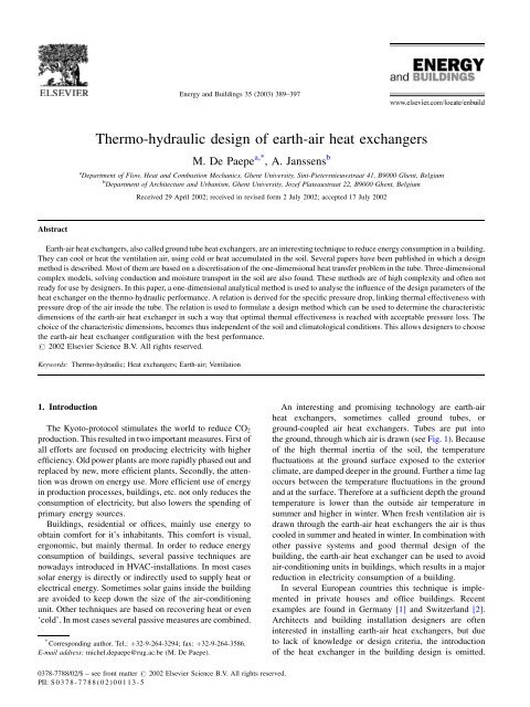
Abstract<br />
<strong>Thermo</strong>-<strong>hydraulic</strong> <strong>design</strong> <strong>of</strong> <strong>earth</strong>-<strong>air</strong> <strong>heat</strong> <strong>exchangers</strong><br />
M. De Paepe a,* , A. Janssens b<br />
a<br />
Department <strong>of</strong> Flow, Heat and Combustion Mechanics, Ghent University, Sint-Pietersnieuwstraat 41, B9000 Ghent, Belgium<br />
b<br />
Department <strong>of</strong> Architecture and Urbanism, Ghent University, Jozef Plateaustraat 22, B9000 Ghent, Belgium<br />
Received 29 April 2002; received in revised form 2 July 2002; accepted 17 July 2002<br />
Earth-<strong>air</strong> <strong>heat</strong> <strong>exchangers</strong>, also called ground tube <strong>heat</strong> <strong>exchangers</strong>, are an interesting technique to reduce energy consumption in a building.<br />
They can cool or <strong>heat</strong> the ventilation <strong>air</strong>, using cold or <strong>heat</strong> accumulated in the soil. Several papers have been published in which a <strong>design</strong><br />
method is described. Most <strong>of</strong> them are based on a discretisation <strong>of</strong> the one-dimensional <strong>heat</strong> transfer problem in the tube. Three-dimensional<br />
complex models, solving conduction and moisture transport in the soil are also found. These methods are <strong>of</strong> high complexity and <strong>of</strong>ten not<br />
ready for use by <strong>design</strong>ers. In this paper, a one-dimensional analytical method is used to analyse the in¯uence <strong>of</strong> the <strong>design</strong> parameters <strong>of</strong> the<br />
<strong>heat</strong> exchanger on the thermo-<strong>hydraulic</strong> performance. A relation is derived for the speci®c pressure drop, linking thermal effectiveness with<br />
pressure drop <strong>of</strong> the <strong>air</strong> inside the tube. The relation is used to formulate a <strong>design</strong> method which can be used to determine the characteristic<br />
dimensions <strong>of</strong> the <strong>earth</strong>-<strong>air</strong> <strong>heat</strong> exchanger in such a way that optimal thermal effectiveness is reached with acceptable pressure loss. The<br />
choice <strong>of</strong> the characteristic dimensions, becomes thus independent <strong>of</strong> the soil and climatological conditions. This allows <strong>design</strong>ers to choose<br />
the <strong>earth</strong>-<strong>air</strong> <strong>heat</strong> exchanger con®guration with the best performance.<br />
# 2002 Elsevier Science B.V. All rights reserved.<br />
Keywords: <strong>Thermo</strong>-<strong>hydraulic</strong>; Heat <strong>exchangers</strong>; Earth-<strong>air</strong>; Ventilation<br />
1. Introduction<br />
Energy and Buildings 35 2003) 389±397<br />
The Kyoto-protocol stimulates the world to reduce CO2<br />
production. This resulted in two important measures. First <strong>of</strong><br />
all efforts are focused on producing electricity with higher<br />
ef®ciency. Old power plants are more rapidly phased out and<br />
replaced by new, more ef®cient plants. Secondly, the attention<br />
was drown on energy use. More ef®cient use <strong>of</strong> energy<br />
in production processes, buildings, etc. not only reduces the<br />
consumption <strong>of</strong> electricity, but also lowers the spending <strong>of</strong><br />
primary energy sources.<br />
Buildings, residential or <strong>of</strong>®ces, mainly use energy to<br />
obtain comfort for it's inhabitants. This comfort is visual,<br />
ergonomic, but mainly thermal. In order to reduce energy<br />
consumption <strong>of</strong> buildings, several passive techniques are<br />
nowadays introduced in HVAC-installations. In most cases<br />
solar energy is directly or indirectly used to supply <strong>heat</strong> or<br />
electrical energy. Sometimes solar gains inside the building<br />
are avoided to keep down the size <strong>of</strong> the <strong>air</strong>-conditioning<br />
unit. Other techniques are based on recovering <strong>heat</strong> or even<br />
`cold'. In most cases several passive measures are combined.<br />
* Corresponding author. Tel.: ‡32-9-264-3294; fax: ‡32-9-264-3586.<br />
E-mail address: michel.depaepe@rug.ac.be M. De Paepe).<br />
0378-7788/02/$ ± see front matter # 2002 Elsevier Science B.V. All rights reserved.<br />
PII: S 0378-778802)00113-5<br />
An interesting and promising technology are <strong>earth</strong>-<strong>air</strong><br />
<strong>heat</strong> <strong>exchangers</strong>, sometimes called ground tubes, or<br />
ground-coupled <strong>air</strong> <strong>heat</strong> <strong>exchangers</strong>. Tubes are put into<br />
the ground, through which <strong>air</strong> is drawn see Fig. 1). Because<br />
<strong>of</strong> the high thermal inertia <strong>of</strong> the soil, the temperature<br />
¯uctuations at the ground surface exposed to the exterior<br />
climate, are damped deeper in the ground. Further a time lag<br />
occurs between the temperature ¯uctuations in the ground<br />
and at the surface. Therefore at a suf®cient depth the ground<br />
temperature is lower than the outside <strong>air</strong> temperature in<br />
summer and higher in winter. When fresh ventilation <strong>air</strong> is<br />
drawn through the <strong>earth</strong>-<strong>air</strong> <strong>heat</strong> <strong>exchangers</strong> the <strong>air</strong> is thus<br />
cooled in summer and <strong>heat</strong>ed in winter. In combination with<br />
other passive systems and good thermal <strong>design</strong> <strong>of</strong> the<br />
building, the <strong>earth</strong>-<strong>air</strong> <strong>heat</strong> exchanger can be used to avoid<br />
<strong>air</strong>-conditioning units in buildings, which results in a major<br />
reduction in electricity consumption <strong>of</strong> a building.<br />
In several European countries this technique is implemented<br />
in private houses and <strong>of</strong>®ce buildings. Recent<br />
examples are found in Germany [1] and Switzerland [2].<br />
Architects and building installation <strong>design</strong>ers are <strong>of</strong>ten<br />
interested in installing <strong>earth</strong>-<strong>air</strong> <strong>heat</strong> <strong>exchangers</strong>, but due<br />
to lack <strong>of</strong> knowledge or <strong>design</strong> criteria, the introduction<br />
<strong>of</strong> the <strong>heat</strong> exchanger in the building <strong>design</strong> is omitted.
390 M. De Paepe, A. Janssens / Energy and Buildings 35 2003) 389±397<br />
Nomenclature<br />
A <strong>heat</strong> transfer area m2 )<br />
cp thermal capacity J/kg K)<br />
D tube diameter m)<br />
h convection coefficient W/mK)<br />
L tube length m)<br />
_m mass flow rate kg/s)<br />
n number <strong>of</strong> tubes<br />
NTU number <strong>of</strong> transfer units<br />
Nu Nusselt number<br />
Pr Prandtl number<br />
Dp pressure drop Pa)<br />
_Q transferred <strong>heat</strong> W)<br />
Re Reynolds number<br />
T temperature K)<br />
DTlm logarithmic temperature difference K)<br />
v velocity m/s)<br />
_V volume flow rate m3 /s)<br />
Greek symbols<br />
E <strong>heat</strong> exchanger effectiveness<br />
l thermal conductivity W/m 2 K)<br />
n kinematic viscosity m 2 /s)<br />
r density kg/m 3 )<br />
Subscripts<br />
<strong>air</strong> <strong>of</strong> the <strong>air</strong><br />
in the inlet <strong>of</strong> the <strong>heat</strong> exchanger<br />
out the outlet <strong>of</strong> the <strong>heat</strong> exchanger<br />
ground <strong>of</strong> the ground<br />
wall <strong>of</strong> the tube wall<br />
In literature, several <strong>design</strong> strategies and calculation methods<br />
are discussed. Most <strong>of</strong> them are based on experiments or<br />
on one-, two- or three-dimensional calculation models. They<br />
are proven to be accurate, but mostly they are highly<br />
complex. Recent experience shows that these methods do<br />
not ®nd their way from an academic level to the every day<br />
practice. Therefore this paper presents an analytical analysis<br />
Fig. 1. Ground-coupled <strong>heat</strong> exchanger.<br />
<strong>of</strong> the <strong>earth</strong>-<strong>air</strong> <strong>heat</strong> exchanger based on the de®nition <strong>of</strong> the<br />
<strong>heat</strong> exchanger effectiveness. With this, the important <strong>design</strong><br />
parameters are studied: tube diameter, tube length and<br />
number <strong>of</strong> tubes. As a result the relative in¯uence <strong>of</strong> these<br />
parameters can be analysed. This results in a <strong>design</strong>-map on<br />
which a proper selection <strong>of</strong> the <strong>design</strong> parameters can be<br />
made.<br />
2. Literature review<br />
In the literature several calculation models for groundcoupled<br />
<strong>heat</strong> <strong>exchangers</strong> are found. Tzaferis et al. studied<br />
eight models [3]. The authors classi®ed the algorithms in<br />
two groups:<br />
1. The algorithms that first calculate the convective <strong>heat</strong><br />
transfer from the circulating <strong>air</strong> to the pipe and then<br />
calculate the conductive <strong>heat</strong> transfer from the pipe to<br />
the ground inside the ground mass. The necessary input<br />
data are:<br />
the geometrical characteristics <strong>of</strong> the system,<br />
the thermal characteristics <strong>of</strong> the ground,<br />
the thermal characteristics <strong>of</strong> the pipe,<br />
the undisturbed ground temperature during the operation<br />
<strong>of</strong> the system.<br />
2. Those algorithms that only calculate the convective <strong>heat</strong><br />
transfer form the circulating <strong>air</strong> to the pipe. In this case<br />
the necessary input data are:<br />
the geometrical characteristics <strong>of</strong> the system,<br />
the thermal characteristics <strong>of</strong> the ground,<br />
the temperature <strong>of</strong> the pipe surface.<br />
Six <strong>of</strong> the models use a steady-state one-dimensional<br />
description <strong>of</strong> the pipe. A relation between inlet and outlet<br />
temperature <strong>of</strong> the tube is derived. For all <strong>of</strong> these models no<br />
in¯uence <strong>of</strong> thermal capacity <strong>of</strong> the <strong>earth</strong> can be taken into<br />
account. Secondly the in¯uence <strong>of</strong> different pipes on each<br />
other cannot be studied. In one algorithm the ground is<br />
divided into co-axial cylindrical elements. The thermal<br />
resistance <strong>of</strong> the ground is considered to be time-dependent.<br />
The pipe is divided in segments. In each segment the exit<br />
temperature is determined. In an other algorithm the steadystate<br />
<strong>heat</strong> balance is solved between a point in the ground<br />
and the tube. The authors conclude that the different models<br />
give comparable results. This is mainly caused by the fact<br />
that the models <strong>of</strong>fer different solution methods and dicretisations<br />
<strong>of</strong> the same equations. The compliance with measurements<br />
done by Tzaferis et al. is quite good. This shows<br />
that a steady-state one-dimensional model may characterize<br />
the behaviour <strong>of</strong> the <strong>earth</strong>-<strong>air</strong> <strong>heat</strong> <strong>exchangers</strong>. This<br />
approach will be followed in this paper.<br />
Mihalakakou et al. [4], Bojic et al. [5], Ghautier et al. [6]<br />
and Hollmuller et al. [7] have reported on more complete<br />
and dynamic models for <strong>earth</strong>-<strong>air</strong> <strong>heat</strong> <strong>exchangers</strong>. The<br />
models differ in the way the geometry is described 2D,<br />
3D, polar coordinates) and in the way the effects <strong>of</strong> moisture
transport in the ground and in the <strong>air</strong> are accounted for.<br />
However, these four calculation methods are quite complex.<br />
They are mainly used to show that the <strong>heat</strong> exchanger is a<br />
promising and effective technology. Therefore the applicability<br />
for <strong>design</strong> is limited to people who are able to use the<br />
calculation codes. In most cases the <strong>earth</strong>-<strong>air</strong> <strong>heat</strong> <strong>exchangers</strong><br />
are just one component in a whole buildings system.<br />
Designers do not have much freedom <strong>of</strong> choice to determine<br />
the size and lay-out <strong>of</strong> the <strong>heat</strong> exchanger. They are limited<br />
by space-constraints and economic boundary conditions.<br />
They need a simpli®ed way to predict the general performance<br />
<strong>of</strong> the <strong>heat</strong> exchanger. Their main concern is to be<br />
able to select a reasonable size <strong>of</strong> the tube diameter, tube<br />
length and number <strong>of</strong> tubes. The most important question<br />
is whether adding another tube or another meter to the<br />
tubes, will result in an economic performance amelioration.<br />
These in¯uences can be derived by the method discussed in<br />
this paper.<br />
3. Design parameter analysis<br />
3.1. Design parameters <strong>of</strong> the <strong>earth</strong>-<strong>air</strong> <strong>heat</strong> exchanger<br />
3.1.1. Specified parameters<br />
The <strong>earth</strong>-<strong>air</strong> <strong>heat</strong> exchanger should be sized in order<br />
to meet certain <strong>design</strong> requirements. For instance, during<br />
cold weather the ventilation <strong>air</strong> at the outlet <strong>of</strong> the <strong>earth</strong>-<strong>air</strong><br />
<strong>heat</strong> exchanger should be <strong>heat</strong>ed above the freezing point<br />
to prevent icing <strong>of</strong> other <strong>heat</strong> recovery components in the<br />
ventilation system. Alternatively, the <strong>air</strong> leaving the <strong>earth</strong><strong>air</strong><br />
<strong>heat</strong> exchanger should deliver total or part <strong>of</strong> the<br />
building cooling load during a <strong>design</strong> summer day. These<br />
<strong>design</strong> requirements are achieved by <strong>heat</strong>ing or cooling<br />
the ventilation <strong>air</strong> in the ground tube from the external<br />
<strong>air</strong> temperature towards the ground temperature in the<br />
vicinity <strong>of</strong> the tube. Hence, by the nature <strong>of</strong> the <strong>design</strong><br />
problem the following parameters <strong>of</strong> the sizing problem<br />
are speci®ed:<br />
_m<strong>air</strong>: the <strong>air</strong> mass flow rate<br />
T<strong>air</strong>;in: the inlet <strong>air</strong> temperature<br />
T<strong>air</strong>;out: the desired outlet <strong>air</strong> temperature after the <strong>heat</strong><br />
exchanger<br />
Tground: the ground temperature<br />
The <strong>air</strong> mass ¯ow rate and the outlet <strong>air</strong> temperature are set<br />
by the <strong>design</strong> requirement. The inlet <strong>air</strong> temperature and the<br />
ground temperature follow from the <strong>design</strong> climate conditions<br />
for the problem.<br />
The ground temperature is de®ned by the external climate<br />
and by the soil composition, its thermal properties and water<br />
content. The ground temperature ¯uctuates in time, but<br />
the amplitude <strong>of</strong> the ¯uctuation diminishes with increasing<br />
depth <strong>of</strong> the tubes, and deeper in the ground the temperature<br />
converges to a practically constant value throughout the<br />
year. Optimal depths are in the range <strong>of</strong> 2±4 m [8].<br />
M. De Paepe, A. Janssens / Energy and Buildings 35 2003) 389±397 391<br />
3.1.2. Dimensions <strong>of</strong> the <strong>heat</strong> exchanger<br />
The geometric sizing parameters <strong>of</strong> an <strong>earth</strong>-<strong>air</strong> <strong>heat</strong><br />
exchanger are:<br />
D: the diameter <strong>of</strong> the tube<br />
L: the length <strong>of</strong> the tube<br />
n: the number <strong>of</strong> tubes in parallel in the <strong>heat</strong> exchanger<br />
Once the number <strong>of</strong> tubes is known, the problem is reduced<br />
to determining the size <strong>of</strong> the tube. The thermo-<strong>hydraulic</strong><br />
problem is then limited to one tube, with an <strong>air</strong> ¯ow rate<br />
given by:<br />
_m<strong>air</strong>;tube ˆ _m<strong>air</strong>;tot<br />
n<br />
For the <strong>design</strong>er, these parameters have to be determined in<br />
such a way that the boundary conditions and the <strong>heat</strong><br />
exchanger performance are met. This means that the location,<br />
the available space, the building <strong>design</strong> and economics<br />
induce restrictions to the choice <strong>of</strong> tube length and number<br />
<strong>of</strong> tubes. It is important to be able to evaluate the in¯uence <strong>of</strong><br />
the parameters on the performance. Different combination <strong>of</strong><br />
these parameters will lead to the same thermal performance.<br />
So a second <strong>design</strong> criterion has to be introduced. Pressure<br />
loss <strong>of</strong> the ¯ow through the tube is <strong>of</strong> main importance for the<br />
quanti®cation <strong>of</strong> the fans in the ventilation system.<br />
3.2. Heat exchanger effectiveness and NTU<br />
In the <strong>earth</strong>-<strong>air</strong> <strong>heat</strong> exchanger <strong>air</strong> is the only <strong>heat</strong><br />
transporting ¯uid. The <strong>heat</strong> released or absorbed by the<br />
<strong>air</strong> is ¯owing through the tube walls to the surrounding soil.<br />
If the contact <strong>of</strong> the tube wall with the <strong>earth</strong> is considered<br />
to be perfect and the conductivity <strong>of</strong> the soil is taken to be<br />
very high compared to the surface resistance, then the wall<br />
temperature at the inside <strong>of</strong> the tube can be assumed to be<br />
constant.<br />
The total <strong>heat</strong> transferred to the <strong>air</strong> when ¯owing through<br />
a buried pipe can be written as:<br />
_Q ˆ _m<strong>air</strong>cp;<strong>air</strong>…T<strong>air</strong>;out T<strong>air</strong>;in† 2)<br />
Due to convection between the wall and the <strong>air</strong>, the transferred<br />
<strong>heat</strong> can be also be written as:<br />
_Q ˆ hADTlm<br />
3)<br />
The logarithmic average temperature difference is given by<br />
…Tground ˆ Twall†:<br />
DTlm ˆ …T<strong>air</strong>;in Twall†…T<strong>air</strong>;out Twall†<br />
ln ‰…T<strong>air</strong>;in Twall†=…T<strong>air</strong>;out Twall†Š<br />
ˆ<br />
T<strong>air</strong>;in T<strong>air</strong>;out<br />
ln ‰…T<strong>air</strong>;in Twall†=…T<strong>air</strong>;out Twall†Š<br />
Eliminating _Q from 2) and 3) gives the exponential relation<br />
for the outlet temperature <strong>of</strong> the tube as function <strong>of</strong> the wall<br />
temperature and inlet temperature:<br />
T<strong>air</strong>;out ˆ Twall ‡…T<strong>air</strong>;in Twall†e<br />
…hA= _m<strong>air</strong>cp;<strong>air</strong>†<br />
1)<br />
4)<br />
5)
392 M. De Paepe, A. Janssens / Energy and Buildings 35 2003) 389±397<br />
If a tube <strong>of</strong> in®nite length …A ˆ1†is used the <strong>air</strong> will be<br />
<strong>heat</strong>ed or cooled to the wall temperature. The effectiveness<br />
<strong>of</strong> <strong>earth</strong>-<strong>air</strong> <strong>heat</strong> exchanger can thus be de®ned as:<br />
E ˆ T<strong>air</strong>;out T<strong>air</strong>;in<br />
Twall T<strong>air</strong>;in<br />
Using 5) the effectiveness becomes<br />
…hA= _m<strong>air</strong>cp;<strong>air</strong>†<br />
E ˆ 1 e 7)<br />
The non-dimensional group is called the number <strong>of</strong> transfer<br />
units NTU).<br />
NTU ˆ hA<br />
which gives<br />
_m<strong>air</strong>cp;<strong>air</strong><br />
E ˆ 1 e NTU<br />
9)<br />
The effectiveness <strong>of</strong> the <strong>heat</strong> exchanger is determined by the<br />
dimensionless group NTU. Fig. 2 shows the change <strong>of</strong> the<br />
effectiveness as function <strong>of</strong> NTU. Increasing the NTU<br />
increases the effectiveness, though the curve rapidly ¯attens.<br />
After NTU > 3, the relative gain is small. There are several<br />
ways to construct an <strong>earth</strong>-<strong>air</strong> <strong>heat</strong> exchanger to obtain a<br />
given NTU and thus a desired effectiveness. The in¯uence <strong>of</strong><br />
the <strong>design</strong> parameters on NTU will now be studied.<br />
3.3. Influence on the <strong>heat</strong> transfer<br />
The NTU consists <strong>of</strong> three parameters which can vary:<br />
h: the convection coefficient <strong>of</strong> the <strong>air</strong> inside the tube<br />
A: the <strong>heat</strong> transfer surface <strong>of</strong> the tube<br />
_m: the <strong>air</strong> mass flow rate<br />
6)<br />
8)<br />
The <strong>heat</strong> transfer area is a function <strong>of</strong> both D and L:<br />
A ˆ pDL 10)<br />
The convection coef®cient inside the tube is de®ned by:<br />
h ˆ Nul<br />
11)<br />
D<br />
The Nusselt number for ¯ow inside a tube is given by [9]:<br />
Nu ˆ 3:66 if Re < 2300<br />
x=8…Re 1000†Pr<br />
Nu ˆ p<br />
1 ‡ 12:7 …x=8† …Pr2=3 1†<br />
with x ˆ…1:82 log Re 1:64† 2<br />
if 2300 Re < 5 10 6<br />
and 0:5 < Pr < 10 6<br />
The ®rst equation applies to fully developed laminar ¯ow,<br />
the second equation applies to turbulent ¯ow in tubes with<br />
smooth internal surfaces. The Reynolds number is related to<br />
average <strong>air</strong> velocity and diameter:<br />
Re ˆ v<strong>air</strong>D<br />
12)<br />
n<strong>air</strong><br />
Fig. 2. Effectiveness as function <strong>of</strong> NTU.<br />
The mass ¯ow rate is given by:<br />
pD<br />
_m<strong>air</strong> ˆ r<strong>air</strong> 2<br />
4 v<strong>air</strong> 13)<br />
The length L is an independent parameter in¯uencing the<br />
NTU. There is a linear variation <strong>of</strong> NTU with length.<br />
Changing the diameter D or the mass ¯ow rate _m both<br />
change the <strong>air</strong> velocity inside the tube. This results in a<br />
changing Reynolds number Re. D and _m have thus no<br />
independent in¯uence on the NTU. As NTU varies linearly<br />
with L, the parameter NTU=L is only depending on D and _m.
This gives:<br />
NTU<br />
L ˆ<br />
hA<br />
ˆ<br />
L _m<strong>air</strong>cp;<strong>air</strong><br />
Nu l<strong>air</strong><br />
D<br />
pDL<br />
r <strong>air</strong> _Vcp;<strong>air</strong>L<br />
l<strong>air</strong> 1<br />
ˆ Nup<br />
cp;<strong>air</strong>r _V <strong>air</strong><br />
14)<br />
For laminar ¯ows Nu is constant, so NTU=L is independent<br />
<strong>of</strong> the diameter D.InFig. 3 the contour lines for NTU=L are<br />
given for small ¯ow rates and large tube diameters. When<br />
the ¯ow is laminar the contour lines become vertical lines.<br />
In Fig. 4 the contour plots for NTU=L with changing range<br />
<strong>of</strong> D and volume ¯ow rate _V for the turbulent ¯ow case are<br />
shown.<br />
In general, lowering D raises the effectiveness, higher<br />
¯ow rates reduce the effectiveness. So it is better to have<br />
several tubes <strong>of</strong> small diameter over which the ¯ow rate is<br />
divided.<br />
Long tubes with a small diameter are pro®table for the<br />
<strong>heat</strong> transfer. They, however, raise the pressure drop in the<br />
tubes, resulting in high fan energy.<br />
3.4. Influence on pressure drop<br />
The pressure drop in a smooth tube is given by:<br />
Dp ˆ x L<br />
D r v2 <strong>air</strong><br />
2<br />
M. De Paepe, A. Janssens / Energy and Buildings 35 2003) 389±397 393<br />
Fig. 3. Contour plot <strong>of</strong> NTU=L as a function <strong>of</strong> diameter and volume flow rate.<br />
15)<br />
with [9]:<br />
x ˆ 64<br />
if Re < 2300<br />
Re<br />
x ˆ…1:82 log Re 1:64† 2<br />
if Re 2300<br />
The tube length L is again an independent parameter in¯uencing<br />
pressure drop. The in¯uence is linear.<br />
Diameter and ¯ow rate have a combined in¯uence. In<br />
Fig. 5 the contour plots <strong>of</strong> pressure drop per unit <strong>of</strong> length<br />
Dp=L for varying diameter and ¯ow rate are shown. Having a<br />
small ¯ow rate per tube and a large diameter gives the least<br />
pressure loss. This would mean using many tubes, with a<br />
large diameter. This is in con¯ict with the thermal demand <strong>of</strong><br />
a small diameter. In both cases a large number <strong>of</strong> tubes is<br />
bene®cial. The tube length and diameter combination have<br />
to be optimized.<br />
4. Heat exchanger <strong>design</strong> calculations<br />
4.1. Specific pressure drop<br />
As both NTU and pressure drop are linear with the tube<br />
length, the parameters NTU=L and Dp=L are only dependent<br />
<strong>of</strong> diameter and volume <strong>air</strong> ¯ow rate. These two parameters<br />
are, respectively, a measure for the thermal and <strong>hydraulic</strong><br />
performance per unit <strong>of</strong> length.
394 M. De Paepe, A. Janssens / Energy and Buildings 35 2003) 389±397<br />
Total NTU and total pressure drop <strong>of</strong> the <strong>heat</strong> exchanger<br />
are given by multiplying these unit parameters with the total<br />
length <strong>of</strong> the tubes:<br />
NTUtot ˆ NTU<br />
L<br />
Dptot ˆ Dp<br />
L<br />
L 16)<br />
L 17)<br />
The speci®c pressure drop J can be de®ned as:<br />
J ˆ Dp<br />
18)<br />
NTU<br />
J is a measure for the pressure drop necessary to realize one<br />
unit <strong>of</strong> NTU.<br />
In Fig. 6 J is given as function <strong>of</strong> _V and D, as calculated<br />
with Eqs. 18), 15), 13) and 8). J grows with growing _V<br />
and smaller D.<br />
The NTU per unit <strong>of</strong> length can be expressed as function<br />
<strong>of</strong> J and pressure drop per unit <strong>of</strong> length as:<br />
NTU<br />
L<br />
1 Dp<br />
ˆ<br />
J L<br />
Fig. 4. Contour plot <strong>of</strong> NTU=L as function <strong>of</strong> diameter and volume flow rate.<br />
19)<br />
4.2. NTU±J <strong>design</strong> method<br />
Given the desired temperature programme the effectiveness<br />
E can be calculated with Eq. 6). With the inverse <strong>of</strong><br />
Eq. 9) the desired NTU can be determined with equation:<br />
NTU ˆ ln …1 E† 20)<br />
This NTU is the minimal desired NTU the <strong>heat</strong> exchanger<br />
has to reach: NTUmin.<br />
Given the maximal allowable pressure drop DpMAX, the<br />
maximal allowable J <strong>of</strong> the <strong>heat</strong> exchanger can be determined<br />
as:<br />
JMAX ˆ DpMAX<br />
NTUmin<br />
21)<br />
This JMAX de®nes a zone in Fig. 6 which is not allowed for _V<br />
and D. The choice <strong>of</strong> D and _V per tube is thus limited.<br />
Combining this with Figs. 3 and 4, the choice for the most<br />
effective <strong>heat</strong> exchanger is the one with the smallest tube<br />
diameter and the smallest ¯ow rate per tube. This allows for<br />
the choice <strong>of</strong> D and the maximum number <strong>of</strong> parallel tubes.<br />
After the number <strong>of</strong> tubes in parallel is chosen and the<br />
tube diameter is accordingly determined the NTU per unit <strong>of</strong>
M. De Paepe, A. Janssens / Energy and Buildings 35 2003) 389±397 395<br />
Fig. 5. Pressure drop Dp=L as function <strong>of</strong> diameter and <strong>air</strong> volume flow rate.<br />
Fig. 6. Specific pressure drop J as function <strong>of</strong> diameter and <strong>air</strong> volume flow rate.
396 M. De Paepe, A. Janssens / Energy and Buildings 35 2003) 389±397<br />
length can be determined by 14). Given the desired NTU,<br />
this gives the length.<br />
4.3. Graphical <strong>design</strong> method<br />
The NTU J <strong>design</strong> method is used to derive a graphical<br />
sizing tool which allows to de®ne the tube length and<br />
diameter from the <strong>air</strong> ¯ow rate per tube and the desired<br />
ground tube performance J. The relationship between the<br />
speci®c pressure drop J and the <strong>air</strong> volume ¯ow rate follows<br />
from Eqs. 14), 15) and 18):<br />
J ˆ 0:258 cp;<strong>air</strong>r2 <strong>air</strong>x 3 _V<br />
l<strong>air</strong>NuD5 Fig. 7. Design graph for the sizing <strong>of</strong> <strong>earth</strong>-<strong>air</strong> <strong>heat</strong><strong>exchangers</strong> with a <strong>heat</strong> exchanger effectiveness <strong>of</strong> 80%.<br />
22)<br />
This relation is represented in the lower half <strong>of</strong> Fig. 6 on a<br />
log±log scale, for different values <strong>of</strong> the tube diameter.<br />
The relationship between the tube length and the speci®c<br />
pressure drop J follows from Eqs. 15), 19), 20) and 22):<br />
L ˆ JNTU<br />
Dp=L ˆ ln …1 E† c2p;<strong>air</strong>r<strong>air</strong>D5 8l 2<br />
<strong>air</strong>xNu2 " # 1=3<br />
J 1=3<br />
23)<br />
This expression may be solved when a value for the effectiveness<br />
E <strong>of</strong> the <strong>earth</strong>-<strong>air</strong> <strong>heat</strong> exchanger is chosen. The<br />
desired effectiveness follows from the <strong>design</strong> requirements<br />
and climate conditions Eq. 7)), but <strong>of</strong>ten an effectiveness<br />
<strong>of</strong> 80% is considered to be an optimum for an <strong>earth</strong>-<strong>air</strong> <strong>heat</strong><br />
exchanger [8]. A higher effectiveness is only achievable at<br />
the cost <strong>of</strong> an important increase <strong>of</strong> the tube length or <strong>of</strong> the<br />
number <strong>of</strong> tubes. Eq. 23) is represented in the upper half <strong>of</strong><br />
Fig. 7, for different values <strong>of</strong> the tube diameter and a <strong>heat</strong><br />
exchanger effectiveness <strong>of</strong> 80%.<br />
The use <strong>of</strong> the <strong>design</strong> graph is now illustrated with an<br />
example. The boundary conditions for the sizing <strong>of</strong> an <strong>earth</strong><strong>air</strong><br />
<strong>heat</strong> exchanger for a small <strong>of</strong>®ce building are the<br />
following:<br />
The <strong>design</strong> <strong>air</strong> flow rate is 750 m3 /h.<br />
The geometry <strong>of</strong> the building site limits the length <strong>of</strong> the<br />
<strong>earth</strong>-<strong>air</strong> <strong>heat</strong> exchanger to a maximum <strong>of</strong> 25 m.<br />
The pressure drop across the <strong>heat</strong> exchanger should not<br />
exceed 100 Pa.<br />
The pressure loss requirement de®nes the maximum allowable<br />
speci®c pressure drop J. Assuming a <strong>heat</strong> exchanger<br />
effectiveness <strong>of</strong> 80%, Eq. 21) gives: J < 62 Pa/m. This<br />
value, together with the requirement for the maximum<br />
individual tube length, delimits a zone <strong>of</strong> allowable L and<br />
J in the upper half <strong>of</strong> Fig. 7. The maximum tube length<br />
depends on the lay-out <strong>of</strong> the tubes on the available strip <strong>of</strong><br />
land Fig. 8). The maximum tube length in the example is<br />
25 m for a bundle <strong>of</strong> parallel tubes, but may be a multiple <strong>of</strong><br />
25 m for a serpentine shape. To prevent interference between<br />
the individual tubes, the distance between them should be at<br />
least 1 m [8].
From the zone <strong>of</strong> allowable L and J in Fig. 7 a suitable<br />
tube diameter may be chosen, closest to the value <strong>of</strong> maximum<br />
speci®c pressure drop. Following the lines <strong>of</strong> equal<br />
speci®c pressure drop J to the line for the chosen diameter in<br />
the lower half <strong>of</strong> the graph, the <strong>air</strong> volume ¯ow rate per tube<br />
is de®ned. The ratio between the <strong>design</strong> <strong>air</strong> ¯ow rate and the<br />
¯ow rate per tube thus de®nes the number <strong>of</strong> tubes <strong>of</strong> a<br />
speci®c diameter and length to be installed. Table 1 shows all<br />
possible combinations which are a solution to the <strong>design</strong><br />
problem <strong>of</strong> the example.<br />
5. Conclusion<br />
Fig. 8. Lay-out <strong>of</strong> ground tubes on a strip <strong>of</strong> land.<br />
Table 1<br />
Heat exchanger configurations for <strong>design</strong> <strong>air</strong> flow rate 750 m 3 /h, E ˆ 80%,<br />
Dp < 100 Pa<br />
D mm) Number<br />
<strong>of</strong> tubes<br />
L per<br />
tube m)<br />
v m/s) Dp Pa) Lay-out<br />
100 4 14 6.6 77 Parallel<br />
150 2 22 5.9 61 Parallel<br />
200 3 25 2.2 8 Parallel<br />
250 1 38 4.2 32 Serpentine<br />
The <strong>design</strong> <strong>of</strong> an <strong>earth</strong>-<strong>air</strong> <strong>heat</strong> exchanger is a separate<br />
problem <strong>of</strong> the building <strong>design</strong>. Once the ventilation<br />
M. De Paepe, A. Janssens / Energy and Buildings 35 2003) 389±397 397<br />
demands are known, the thermo-<strong>hydraulic</strong> <strong>design</strong> <strong>of</strong> the<br />
<strong>heat</strong> exchanger only depends on the constructional constraints<br />
and economics.<br />
Three dimensions have to be determined: tube length,<br />
tube diameter and number <strong>of</strong> parallel tubes. Thermal performance<br />
and pressure drop both grow with length. Smaller<br />
tube diameters give better thermal performance, but also<br />
larger pressure drop. More tubes in parallel both lower<br />
pressure drop and rise thermal performance.<br />
To be able to reduce the in¯uencing parameters the<br />
speci®c pressure drop is introduced. The speci®c pressure<br />
drop is a measure for the pressure drop needed to realize a<br />
given thermal performance. This way a maximal speci®c<br />
pressure drop can be calculated.<br />
The speci®c pressure drop is used to derive a straight<br />
forward <strong>design</strong> method.<br />
References<br />
[1] M. Schuler, Design for daylighting and energy in Ingolstadt,<br />
Advanced Building Newsletter 23/24 1999) 18±23.<br />
[2] M. Zimmermann, The Schwerzenbacherh<strong>of</strong> <strong>of</strong>fice and industrial<br />
building Swerzenbach, Switzerland, ground cooling <strong>air</strong>), IEA Low<br />
Energy Cooling Demonstration 15/1±15/8, 1998.<br />
[3] A. Tzaferis, D. Liparakis, M. Santamouris, A. Argiriou, Analysis <strong>of</strong><br />
the accuracy and sensitivity <strong>of</strong> eight models to predict the performance<br />
<strong>of</strong> <strong>earth</strong>-to-<strong>air</strong> <strong>heat</strong> <strong>exchangers</strong>, Energy and Buildings 18 1992)<br />
35±43.<br />
[4] G. Mihalakakou, M. Santamouris, D. Asimakopoulos, Modelling the<br />
thermal performance <strong>of</strong> <strong>earth</strong>-to-<strong>air</strong> <strong>heat</strong> <strong>exchangers</strong>, Solar Energy 53<br />
3) 1994) 301±305.<br />
[5] M. Bojic, N. Trifunovic, G. Papadakis, S. Kyritsis, Numerical<br />
simulation, technical and economic evaluation <strong>of</strong> <strong>air</strong>-to-<strong>earth</strong><br />
<strong>heat</strong> exchanger coupled to a building, Energy 22 12) 1997) 1151±<br />
1158.<br />
[6] C. Gauthier, M. Lacroix, H. Bernier, Numerical simulation <strong>of</strong> soil <strong>heat</strong><br />
exchanger-storage systems for greenhouses, Solar energy 60 6) 1997)<br />
333±346.<br />
[7] P. Hollmuller, B. Lachal, Cooling and pre<strong>heat</strong>ing with buried pipe<br />
systems: monitoring, simulation and economic aspects, Energy and<br />
Buildings 33 5) 2001) 509±518.<br />
[8] IEA Annex 28, Early <strong>design</strong> guidance for low energy cooling<br />
technologies, International Energy Agency, Energy Conservation in<br />
Buildings and Community Systems Programme, Annex 28 Low<br />
Energy Cooling, Subtask 2, Report 2, 1999.<br />
[9] VDI, WaÈrmeatlas, Springer, Verlag, 1994.