AN108711 - NXP Semiconductors
AN108711 - NXP Semiconductors
AN108711 - NXP Semiconductors

You also want an ePaper? Increase the reach of your titles
YUMPU automatically turns print PDFs into web optimized ePapers that Google loves.
Philips <strong>Semiconductors</strong><br />
1.4.2.1 Initial RF Collision Avoidance / Detection<br />
Application Note<br />
Tips and Tricks for PN51x Integration<br />
The RF Collision Avoidance (RFCA) 6 in active mode is based on two techniques:<br />
• RF field sensing<br />
In discrete time frames the Initiator / Target checks if there is already an RF field<br />
- or during communication - if there is a violation due to an invalid CRC.<br />
• Time Jitter<br />
The initiation of certain commands depends on a randomly chosen time offset. In<br />
the NFCIP-1 protocol there are four possible discrete time frames which are<br />
selected on a random basis. This prevents having deadlock situations.<br />
The RFCA is performed as follows:<br />
The Initiator first checks if already an RF field can be detected. If there is no RF field for a<br />
time greater than TIDT , plus a random time frame (n * TRFW), the initiator activates the RF<br />
field. This time frame gives other initiators the chance to detect that another Initiator has<br />
already started the RFCA (RF Collision Avoidance) sequence. Now the initiator can send<br />
an initial ATR_REQ. After the command has been issued, the initiator switches off the RF<br />
field and waits for an ATR_RES from at least one target. The initiation of the ATR_RES<br />
follows the same strategy as for the ATR_REQ. This means that the target also starts at<br />
a random time frame and also checks if there is already a target, which has already<br />
switched on the RF field. If the Target has already detected an RF field (i.e. there is<br />
another Target in the RF field) it won’t respond by an ATR_RES.<br />
Although the RFCA is sufficient in most cases, it sometimes can happen that at least two<br />
initiators or targets are modulating at the same time. In order to detect these conflicts, the<br />
PN51x checks the hardware calculated CRC values from the ATR_REQ and ATR_RES.<br />
If there was an error the selection process has to be repeated.<br />
After the ATR_REQ/ATR_RES pair has been established, collisions shouldn’t occur any<br />
more. Therefore the time-jitter, which is generated by hardware, is switched off. However,<br />
according to NFCIP-1 CRC checks shall be performed throughout the whole<br />
communication.<br />
1.4.3 Bit Representation<br />
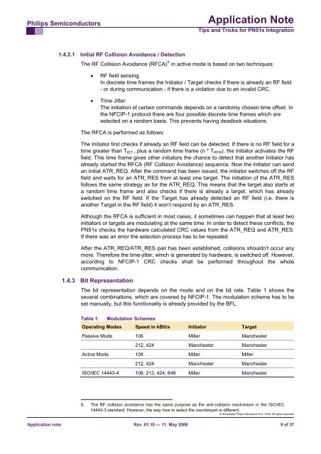
The bit representation depends on the mode and on the bit rate. Table 1 shows the<br />
several combinations, which are covered by NFCIP-1. The modulation scheme has to be<br />
set manually, but this functionality is already provided by the BFL.<br />
Table 1: Modulation Schemes<br />
Operating Modes Speed in kBit/s Initiator Target<br />
Passive Mode 106 Miller Manchester<br />
212, 424 Manchester Manchester<br />
Active Mode 106 Miller Miller<br />
212, 424 Manchester Manchester<br />
ISO/IEC 14443-4 106, 212, 424, 848 Miller Manchester<br />
6. The RF collision avoidance has the same purpose as the anti-collision mechanism in the ISO/IEC<br />
14443-3 standard. However, the way how to select the counterpart is different.<br />
© Koninklijke Philips Electronics N.V. 2006. All rights reserved.<br />
Application note Rev. 01.10 — 11. May 2006 9 of 37