Turning Gear for Gas Turbines - Voith Turbo
Turning Gear for Gas Turbines - Voith Turbo
Turning Gear for Gas Turbines - Voith Turbo

You also want an ePaper? Increase the reach of your titles
YUMPU automatically turns print PDFs into web optimized ePapers that Google loves.
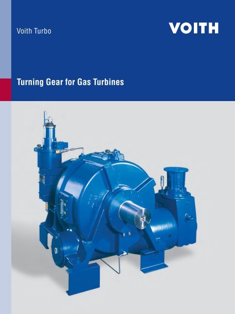
<strong>Turning</strong> <strong>Gear</strong> <strong>for</strong> <strong>Gas</strong> <strong>Turbines</strong>
Design<br />
<br />
<br />
Within the last 25 years, <strong>Voith</strong> has<br />
supplied more than 5 000 hydrodynamic<br />
torque converters and more<br />
than 1 000 of those with integrated<br />
turning gears <strong>for</strong> starting and turning<br />
gas turbines. These combined<br />
units have starting powers from<br />
400 kW up to 10 000 kW. The torque<br />
range of the turning gears varies<br />
from 6 000 to 110 000 Nm. However,<br />
greater torque values can easily be<br />
offered. With this experience we are<br />
now taking the next logical step in<br />
our product line with ”free standing”<br />
turning gears.<br />
<br />
The use of our well proven design<br />
from the integrated version provides<br />
the same outstanding reliability, availability<br />
and service life our customers<br />
are used to. Also our customers can<br />
take advantage of our well established<br />
and worldwide service network.<br />
<br />
<br />
<br />
<br />
1. Inner ring of overrunning clutch<br />
2. Outer ring of overrunning clutch<br />
3. Cage with clamping pieces<br />
4. <strong>Turning</strong> gear output shaft<br />
5. Housing<br />
6. Worm gear wheel<br />
7. Worm gear shaft<br />
8. Bevel gear (with overload<br />
limitation if required)<br />
9. Electric motor with manual turning<br />
capability<br />
10. Antifriction bearings <strong>for</strong> worm<br />
gear wheel<br />
11. Antifriction bearings <strong>for</strong> worm<br />
gear shaft<br />
12. Radial sleeve bearing<br />
13. Thrust bearing<br />
14. Lube oil supply<br />
15. Lube oil drain<br />
16. Connection coupling
Function<br />
The inner ring (1) is connected to<br />
the output shaft (4), and the outer<br />
ring (2) to the worm gear (6). The<br />
cage with the clamping pieces (3)<br />
is connected to the inner ring (1).<br />
The worm gear wheel (6) is driven<br />
through the worm gear shaft (7)<br />
and the bevel gear (8) is driven by<br />
the electric motor (9).<br />
The antifriction bearings (10, 11)<br />
support the worm gear set in the<br />
housing. The worm gear uses a<br />
constant oil fi lling, independent of<br />
the gas turbines oil supply.<br />
The sleeve and thrust bearings<br />
(12, 13) support the output shaft in<br />
the housing. These bearings are<br />
supplied with lube oil from the gas<br />
turbine oil system.<br />
The cage with the clamping pieces<br />
(3) always rotates with the output<br />
shaft (4). Even a low speed of the<br />
output shaft (4) lifts the clamping<br />
pieces (3) due to centrifugal <strong>for</strong>ce<br />
of the outer ring (2). Consequently<br />
the outer ring (2) is no longer connected<br />
to the inner ring (1). During<br />
gas turbine operation the overrunning<br />
clutch operates without contact<br />
and thus wear free.<br />
If the gas turbine speed decreases<br />
to a value below 200 rpm, the centrifugal<br />
<strong>for</strong>ce decreases to such an<br />
extent that the clamping pieces (3)<br />
touch the outer ring (2) again due to<br />
spring tension. If the inner ring (1)<br />
now rotates slower than the outer<br />
ring (2), the overrunning clutch is<br />
engaged and a torque can be transmitted<br />
from the outer ring (2) to the<br />
inner ring (1).<br />
The torque can only be transmitted<br />
in one predetermined direction of<br />
rotation.<br />
An overload limitation can be used<br />
to protect the internal parts of the<br />
gear and the gas turbine or generator<br />
related parts against excessive<br />
torque.<br />
The following output shaft speeds<br />
(gas turbine) can exist, when the<br />
motor of the turning device is<br />
switched on:<br />
■ Output speed = 0:<br />
The overrunning clutch is engaged;<br />
the gas turbine breaks away<br />
■ Output speed < outer ring speed:<br />
The overrunning clutch is engaged;<br />
the gas turbine is accelerated<br />
to turning speed<br />
■ Output speed > outer ring speed:<br />
The overrunning clutch is disengaged;<br />
no infl uence on the gas<br />
turbine speed<br />
Scope of supply<br />
■ <strong>Turning</strong> gear<br />
■ Attached base structure to „adapt“<br />
to customers foundation<br />
(upon request)<br />
■ Connection coupling between<br />
turning gear and generator<br />
■ Electric motor<br />
■ Manual turning device<br />
■ Piping to locate lube oil feed &<br />
drain connections in customer<br />
specifi ed location (upon request)<br />
■ Coupling guard<br />
■ Factory assembling and testing<br />
Data worksheet<br />
Specifi c technical data<br />
worksheet<br />
■ The unit is used <strong>for</strong><br />
___________________________<br />
gas turbine.<br />
■ The design is according to<br />
<strong>Turning</strong> <strong>Gear</strong> Specifi cation<br />
___________________________<br />
Customer to defi ne:<br />
■ <strong>Turning</strong> speed<br />
__________________ rpm<br />
■ Break away torque<br />
__________________ ftlb or Nm<br />
■ Continuous torque<br />
__________________ ftlb or Nm<br />
■ Direction of rotation<br />
(looking in direction of power fl ow)<br />
CW CCW<br />
■ Voltage _____ DC or<br />
_____ AC _____ Hz _____ Phase<br />
■ Required design margin <strong>for</strong> break<br />
away torque<br />
__________________<br />
<strong>Voith</strong> to defi ne:<br />
■ Speed of electric motor<br />
__________________ rpm<br />
■ Power of electric motor<br />
(continuous operation)<br />
__________________ kW<br />
■ Lube oil supply<br />
__________________<br />
■ Ratio of bevel gear<br />
__________________<br />
■ Ratio of worm gear<br />
__________________
<strong>Voith</strong> <strong>Turbo</strong> GmbH & Co. KG<br />
Variable-speed drives<br />
<strong>Voith</strong>straße 1<br />
74564 Crailsheim<br />
Tel. +49 7951 32-0<br />
Fax +49 7951 32-650<br />
vs.drives@voith.com<br />
www.variable-speed.com<br />
www.voithturbo.com<br />
Cr 289 e KO/WA 07/2007 Print run 2000. Printed in Germany. Subject to modifications due to technical development.