Download PDF - Voith Turbo
Download PDF - Voith Turbo
Download PDF - Voith Turbo

You also want an ePaper? Increase the reach of your titles
YUMPU automatically turns print PDFs into web optimized ePapers that Google loves.
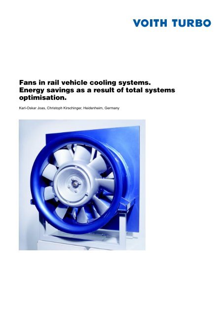
Fans in rail vehicle cooling systems.<br />
Energy savings as a result of total systems<br />
optimisation.<br />
Karl-Oskar Joas, Christoph Kirschinger, Heidenheim, Germany<br />
1
2<br />
Contents<br />
1. Introduction 3<br />
2. History and technical development 3<br />
3. Operation of cooling system fans 6<br />
3.1 Drive and control 7<br />
3.1.1 Mechanical / hydrodynamic drive 7<br />
3.1.2 Hydrostatic drive 8<br />
3.1.3 Electrical drive 10<br />
3.2 Design and rating of the radiator 10<br />
3.3 Cooling air demand, flow resistances, and safety margins 12<br />
3.4 Arrangement of the fan 13<br />
3.5 Fan operating points 14<br />
3.6 Noise emission and sound insulation 15<br />
4. Modern cooling systems and their design 16<br />
5. Economical considerations 17<br />
6. Summary 18<br />
References 18
Summary<br />
Fans are a key component in rail vehicle<br />
cooling system. This fact has been recognised<br />
by <strong>Voith</strong> <strong>Turbo</strong> GmbH & Co. KG,<br />
Heidenheim, who consequently developed<br />
a special range of cooling fans.<br />
All fans from this range have modular<br />
design and can be adapted to any application.<br />
They ensure that cooling systems<br />
run with maximum efficiency, offering<br />
the customer excellent benefits.<br />
The concept of a cooling system is determined<br />
by the synergies between the<br />
fan, the heat exchangers, the prevailing<br />
operating conditions and the<br />
driveline designs of individual rail vehicle<br />
types, as well as by the way in which<br />
they are installed. Intelligent arrangements<br />
of the components and optimum<br />
aerodynamic designs result in high<br />
efficiencies of the fans and fan drives.<br />
Initial investment costs for aerodynamic<br />
layout schemes and higher purchasing<br />
costs for high-quality components pay<br />
off within just a few years.<br />
1. Introduction<br />
The increasing use of diesel engines<br />
by railway operators since the 50s created<br />
a high demand for powerful rail vehicle<br />
cooling systems and thus also for<br />
high-quality fans. A wide range of fans<br />
evolved and was systematically improved<br />
and adapted to the requirements<br />
and installation characteristics of<br />
the components to be cooled.<br />
Fans are driven by auxiliary energy and<br />
are used for dissipating waste heat from<br />
power-transmitting machines. The<br />
smaller the required amount of auxiliary<br />
energy for the same quantity of dissipated<br />
heat, the more economical the<br />
overall system.<br />
For best results it is important to examine<br />
the entire aerodynamic system with<br />
all the parts exposed to the air flow and<br />
not just the fan alone. Intelligent speed<br />
control is a prerequisite of a favourable<br />
energy balance, too. And finally, aspects<br />
such as cost, environmental conditions,<br />
noise emission, and reliability<br />
must be taken into account.<br />
From this point of view, the main task<br />
for project engineers of cooler manufacturers<br />
is to optimally match the various<br />
components necessary for overall<br />
performance of the aerodynamic part<br />
of the cooling system to each other.<br />
A high knowledge of the technical conditions<br />
in the vehicle and several iteration<br />
steps when planning the aerodynamic<br />
system are required for this,<br />
since it is obviously impossible to create<br />
optimum operating conditions for all<br />
the components at the same time due<br />
to the prevailing boundary conditions<br />
and the available space. A compromise<br />
made for the design of one of the components<br />
often has a positive influence<br />
on overall efficiency.<br />
3
2. History and technical development<br />
The development of axial-flow fans by<br />
<strong>Voith</strong> <strong>Turbo</strong>, Heidenheim, began in 1930,<br />
i. e. at the same time as the first turbo<br />
transmissions were developed, with<br />
research work by Marcinowski [1 to 3].<br />
As early as 1932, <strong>Voith</strong> supplied a large<br />
impeller for an axial-flow fan in a wind<br />
tunnel. In the following years, development<br />
concentrated on different impeller<br />
blades and vanes. The different designs<br />
formed a modular system that permitted<br />
fans to be adapted to different operating<br />
conditions in a highly flexible<br />
way.<br />
Later, the development of axial-flow<br />
fans was supplemented by that of radial-flow<br />
and cross-flow fans leading to<br />
wind turbines and a multi-stage axial<br />
compressor for research purposes.<br />
This opened up a wide range of possible<br />
applications for our fans:<br />
- stationary applications in paper<br />
machines,<br />
- large-scale building ventilation,<br />
-fans for underground mining,<br />
- tunnel ventilation using fixed or<br />
variable-pitch blades,<br />
-fans in power stations, especially for<br />
flue gas desulphurization plants and<br />
wind tunnels,<br />
-fans in vehicles, especially as a part<br />
of <strong>Voith</strong> cooling systems for rail<br />
vehicles, and in snow guns.<br />
4<br />
The versatile and comprehensive<br />
modular system developed by<br />
Marcinowski for axial-flow fans can be<br />
used for both directions of rotation in<br />
the following configurations:<br />
- impeller with cap suitable for both<br />
flow directions,<br />
- same impeller as above, yet with<br />
guide vanes for certain blade<br />
designs,<br />
- impeller with guide vanes (mainly<br />
on downstream side) and downstream<br />
centre fairing for certain<br />
blade designs,<br />
- impeller with guide vanes (mainly<br />
on downstream side) and external<br />
diffuser, and<br />
- special versions derived from the<br />
above.<br />
The types of blading and blade designs<br />
for different pressure stages are divided<br />
into basic groups with defined hub/tip<br />
ratios ν (ν = hub dia. / impeller blade tip<br />
dia., table 1):<br />
Type<br />
Hub/tip ratio<br />
d<br />
ν =<br />
D<br />
d<br />
D<br />
∆p t = max. total pressure<br />
difference<br />
in Pa<br />
Distributor<br />
without with<br />
N 0.315 ≈ 1000 –<br />
M 0.5 ≈ 1500 ≈ 2000<br />
H 0.63 ≈ 2000 ≈ 2500<br />
Table 1: Hub/tip ratio and total pressure difference for certain types in<br />
the range of standardized hub/tip ratios:<br />
0,28 / 0,315 / 0,355 / 0,4 / 0,45 / 0,5 / 0,56 / 0,63 / 0,71<br />
• The size ranges of hub and tip<br />
diameter are based on the R 20<br />
series of preferred numbers as per<br />
DIN 323.<br />
• The number of blades and their<br />
angle of attack can be varied as<br />
required (even for cast impellers<br />
thanks to the modular system). The<br />
same applies to the guide vanes.<br />
•For the sake of simplicity the<br />
principle of stating specific power<br />
via flow coefficient ϕ and pressure<br />
coefficient ψ has been transformed<br />
into a work sheet (fig. 1) with fulllogarithmic<br />
coordinate system<br />
showing a family of straight lines for<br />
- outer impeller diameter and<br />
- speed (together with the resulting<br />
tip speed).<br />
• The work sheet (fig. 1) shows the<br />
relation between the specific energy<br />
Y (flow resistance ∆ρ referred to<br />
an air density of ρ = 1 kg/m3 ) and<br />
•<br />
the volume flow VL for one type of<br />
impeller and one hub/tip ratio.<br />
Characteristic ranges found during<br />
tests are used for the various hub/<br />
tip ratios. Size, design, and further<br />
technical features of a fan with a
specified working point (L in fig. 1)<br />
can be defined with the aid of the<br />
work sheet and further dimensionless<br />
characteristic diagrams (not<br />
shown here) for various fans differing<br />
from each other in the abovementioned<br />
features by superposing<br />
the two graphs.<br />
The modular system developed by<br />
Marcinowski was thus supplemented<br />
by a tool for selecting the best fan for<br />
a given application.<br />
The influence of the number of blades<br />
and the impeller clearance gap on fan<br />
characteristics and noise emission<br />
[1, 2] were measured as well. The clearance<br />
gap depends exclusively on the<br />
accuracy of manufacture of impeller<br />
and shroud.<br />
For rail vehicle applications, characteristic<br />
diagrams were prepared that take<br />
into account the arrangement of the<br />
fans and the flow behaviour under the<br />
different geometric conditions that prevail<br />
in such vehicles. These empirical<br />
findings were taken as a basis for the<br />
proprietary software programs used for<br />
calculating flow loss in cooling systems.<br />
In view of increasingly stringent demands<br />
made on cooling systems and<br />
new developments in the field of radiator<br />
elements, the fan system was further<br />
perfected with the aim of achieving<br />
a highly uniform flow velocity in the<br />
annular surface of the fan while increasing<br />
efficiency for common working<br />
points. The result were two new blade<br />
designs, one for an impeller without<br />
guide vanes and one for an impeller<br />
with outlet vanes.<br />
These new blade designs permit deviations<br />
from the standard outer diameters,<br />
allowing higher flexibility of adaptation<br />
to different installation conditions.<br />
Other benefits include a further<br />
optimization of the fan design and adaptation<br />
to the fan drive used.<br />
Y in Nm/kg<br />
Speed n in 1/min<br />
D in mm<br />
2000<br />
1800<br />
1600<br />
1400<br />
1200<br />
B<br />
D = 710<br />
3500<br />
D = 800<br />
3000<br />
2850<br />
2400<br />
1000<br />
VL in m3 5 6 7<br />
/s<br />
8 9 10<br />
L<br />
D = 900<br />
2600<br />
2000<br />
1800<br />
D = 1000<br />
2200<br />
Fig. 1: Detail of work sheet for determining fan diameter, fan speed,<br />
and fan type.<br />
B = Example of a reference point for superposition with the<br />
characteristic range of a fan. The non-dimensional<br />
characteristic diagram of a fan (not shown) is applied at<br />
the reference points. The aim is to select a fan type<br />
whose performance curve contains a specific<br />
performance point L.<br />
L = Example of a performance point for which a fan characteristic<br />
is sought.<br />
Tests have been made at the <strong>Voith</strong><br />
Aerodynamics Test Centre to examine<br />
the air flow in cooling systems of rail<br />
vehicles in tunnels. The effects of different<br />
vehicle front end designs on air<br />
flow around the vehicles were also<br />
tested at different speeds. The arrangement<br />
of air inlets and outlets was<br />
optimized in tests, and pressures were<br />
measured so that they could be taken<br />
into account for fan design. For special<br />
applications these findings help deciding<br />
on the power reserves to be provided<br />
[3].<br />
5
3. Operation of cooling system fans<br />
Fan design depends on the following<br />
factors:<br />
- the type of vehicle and thus the type<br />
and arrangement of the cooling<br />
system in the vehicle,<br />
- the nature of the components to be<br />
cooled and the type of coolant,<br />
- the type of drive and control of the<br />
fan and cooler group,<br />
- the operating mode and design of<br />
heat exchangers, and<br />
- the total flow loss of the system.<br />
It has become apparent over time that<br />
certain arrangements, cooling system<br />
types, and fan drives should be preferred<br />
depending on vehicle type.<br />
6<br />
Fig. 2: Axial flow fan<br />
For locomotives, the cooler group can<br />
usually be arranged next to the component<br />
to be cooled. For railcars and<br />
trainsets with underfloor powerpacks a<br />
greater distance may be necessary or<br />
the cooler group may have to be arranged<br />
under the roof of the vehicle.<br />
Sometimes, the axial-flow fans (fig. 2)<br />
mostly used in cooling systems are replaced<br />
by radial-flow fans today if the<br />
installation conditions and ratings are<br />
favourable and noise is to be minimized.<br />
In the majority of cases, however, axialflow<br />
fans are adequate for the total<br />
pressure loss mostly found today.<br />
Moreover, axial-flow fans can be easily<br />
adapted to the required cooling air<br />
flows. With radial-flow fans, in contrast,<br />
the possible pressure head cannot be<br />
utilized. Cooling air flow is limited due<br />
to the limited intake velocity of air in the<br />
∆ptot in Pa<br />
600<br />
500<br />
400<br />
300<br />
200<br />
100<br />
Fan characteristic<br />
η = 0,58<br />
η = 0,75<br />
intake funnel so that efficiency levels<br />
remain unsatisfactory, as can be seen<br />
from the location of the working point<br />
on the performance curves (fig. 3). The<br />
working points where efficiency is<br />
higher are further to the left or right on<br />
the performance curve of the fan and<br />
cannot be reached in practice.<br />
Cross-flow fans are rarely used in rail<br />
vehicles. Their advantages regarding<br />
the arrangement of radiator and fan are<br />
offset by an extremely low pressure<br />
head and low efficiency, among other<br />
things.<br />
η = 0,74<br />
0<br />
0 0,3 0,6 0,9 1,2 1,5 1,8<br />
V L in m 3 /s<br />
Fig 3: Performance curve of a radial-flow fan without spiral<br />
case in an underfloor-mounted cooling unit.<br />
B = Operating point<br />
B<br />
η = 0,53<br />
System characteristic
3.1 Drive and control<br />
Today, the drive and control of the fan<br />
cannot be separated any longer from<br />
coolant temperature control. Both are<br />
performed using advanced electronic<br />
systems. The requirement is to keep the<br />
operating temperature of the components<br />
to be cooled as constant as possible<br />
and to maintain close temperature<br />
limits for certain operating conditions,<br />
irrespective of variables such as drive<br />
speed, loading condition, or cooling air<br />
temperature.<br />
For all liquid-cooled components, temperature<br />
control of the system is realized<br />
via speed control of the fan and<br />
carefully matched to the thermal behaviour<br />
of the system, taking into account<br />
the overall concept of the cooling circuit.<br />
This presupposes the availability<br />
of information and knowledge about the<br />
different characteristic operating conditions<br />
of the components to be cooled.<br />
With modern diesel engines, the thermal<br />
characteristics of the start-up<br />
phase and the effects of prolonged<br />
idling are of particular importance. Additionally,<br />
the partially conflicting requirements<br />
of cylinder cooling and<br />
charge-air cooling in the case of single-circuit<br />
systems and the interaction<br />
of the circuits in the case of two-circuit<br />
systems must be considered. For engines<br />
with charge-air-air cooling, in<br />
particular, care must be taken to prevent<br />
critical operating conditions such<br />
as excessive cooling or overheating.<br />
Further development of diesel engines<br />
to improve efficiency and more stringent<br />
exhaust gas regulations in conjunction<br />
with the use of exhaust gas<br />
turbochargers have resulted in an increase<br />
in operating temperatures. The<br />
higher coolant temperatures resulting<br />
from this require higher safety in respect<br />
of coolant circulation. Moreover,<br />
the reduced temperature margin up to<br />
the failure limit caused by the higher<br />
operating temperatures makes it necessary<br />
to define the control temperature<br />
range even more accurately than<br />
it was the case with older types of<br />
diesel engine.<br />
With diesel-hydraulic vehicles, waste<br />
heat from the hydrodynamic transmission<br />
and from the hydrodynamic brake,<br />
if any, must be dissipated in addition.<br />
The situation with regard to transformer<br />
cooling is less complex and easier to<br />
understand. Temperatures in the cooling<br />
circuit are usually lower than in the<br />
case of engine cooling, and they<br />
change less quickly due to the high<br />
transformer mass. The control is<br />
matched to the operating conditions of<br />
the transformer, preventing both excessive<br />
temperatures and excess cooling<br />
when ambient temperature is low. Coolant<br />
circulation problems can occur<br />
when the system is started at a very<br />
low temperature and coolant flow<br />
through the radiator element is impaired<br />
or even inhibited by a highly viscous<br />
coolant. This situation cannot be handled<br />
by the temperature control alone<br />
but requires selection of a suitable coolant.<br />
Converter cooling requires a comparatively<br />
high cooling air flow rate due to<br />
the small difference between operating/<br />
coolant temperature and ambient temperature.<br />
In countries with a hot climate<br />
the coolant temperature is only marginally<br />
higher than the ambient temperature.<br />
The high efficiency of present day<br />
converters is due to the use of temperature-sensitive<br />
components with a low<br />
mass. Adherence to close temperature<br />
limits and avoidance of excess tem-<br />
peratures are essential for a long service<br />
life and high efficiency of these converter<br />
elements. This presupposes reliable<br />
temperature control and quick<br />
response of the fan drive control.<br />
When the converter and transformer<br />
are both cooled by the same fan, unfavourable<br />
or extreme conditions may<br />
require concessions to be made for one<br />
of the two cooling circuits. This also applies<br />
when further electrical components<br />
in the cooler group are to be<br />
cooled directly by the cooling air flow.<br />
There are three different approaches<br />
towards meeting the above demands<br />
regarding cooling system control and<br />
fan speed control for the fan drive.<br />
3.1.1 Mechanical /<br />
hydrodynamic drive<br />
The simplest way of driving a fan - with<br />
the cooler group arranged directly next<br />
to the power pack - would be a purely<br />
mechanical, rigid drive without control<br />
options. Fan speed would then be coupled<br />
to the speed of the prime mover,<br />
usually a diesel engine. This is an inadequate<br />
solution because of the fluctuations<br />
in operating temperature that<br />
result in changes in the required cooling<br />
capacity due to different load stages<br />
and ambient temperatures. Even the<br />
addition of system components like<br />
coolant temperature controllers or mixers<br />
would not make this type of drive<br />
efficient.<br />
The shortcomings of cooling systems<br />
with rigidly coupled fan and prime<br />
mover led to the development of mechanical/hydrodynamic<br />
and hydrostatic<br />
drive systems for diesel-powered vehicles<br />
that offer different control options<br />
and high flexibility with regard to fan<br />
speed.<br />
7
The core component of the mechanical/hydrodynamic<br />
drive system is the<br />
<strong>Voith</strong> variable-speed fan, which is available<br />
in various versions. Its distinctive<br />
feature is that it forms an integral unit<br />
with a filling-controlled Föttinger coupling.<br />
A pneumatic system is used for<br />
filling control - and thus for control of<br />
the fan speed - that uses the coolant<br />
temperature of the components to be<br />
cooled as output variable [4, 5].<br />
The advantages of the <strong>Voith</strong> variablespeed<br />
fan can be summarized as follows:<br />
- The system permits a constant<br />
coolant and component temperature<br />
to be maintained.<br />
-Fan speed can be varied within<br />
certain limits and is only dependent<br />
on diesel engine speed to a certain<br />
extent.<br />
- The efficiency maximum of about<br />
90 % for the entire driveline is<br />
reached at maximum fan speed,<br />
i. e. when the coupling is full.<br />
-Power consumption is matched to<br />
the operating conditions.<br />
- The system is self-sufficient.<br />
- The system is considered robust,<br />
long-lived, low-maintenance, and<br />
vibration-resistant.<br />
The disadvantages are:<br />
- Lack of flexibility with regard to arrangement<br />
in the vehicle due to the<br />
mechanical drive.<br />
- High cost and weight.<br />
The hydrodynamic fan drive was therefore<br />
replaced by the hydrostatic one.<br />
8<br />
3.1.2 Hydrostatic drive<br />
The hydrostatic drive system for fans<br />
and other auxiliary machines is considered<br />
state-of-the-art for today’s dieselpowered<br />
vehicles with all its hydraulic<br />
components including electronic control.<br />
The advantages of this system are<br />
a high freedom of choice regarding the<br />
arrangement of the components in the<br />
vehicle and the favourable price of the<br />
entire cooler group.<br />
In principle it is possible to design a<br />
hydrostatic drive in such a way that it is<br />
only a hydraulic shaft without any possibility<br />
of control. The simplest type of<br />
control would be a pure on-off control.<br />
Both these designs are simple and trouble-free<br />
in respect of their operation, but<br />
they do not come up to today’s demands<br />
any longer and have therefore<br />
become insignificant.<br />
There are highly developed components<br />
and regulating valves available<br />
Temperature<br />
sensors<br />
Standby<br />
valve<br />
Diesel<br />
engine<br />
Variabledisplacement<br />
pump<br />
Control electronics<br />
Control valve<br />
Constantdisplacement<br />
motor<br />
Oil filter<br />
Oil tank<br />
Fig. 4: <strong>Voith</strong> flow system driving a cooling fan<br />
today for variable-speed hydrostatic<br />
drives. Several patented solutions have<br />
emerged over the last few years both<br />
for overall function and for control.<br />
The use of a variable-displacement<br />
pump that only delivers the oil flow actually<br />
required for cooling has resulted<br />
in a higher overall efficiency. Moreover,<br />
the <strong>Voith</strong> flow system with variable-displacement<br />
pump includes a stand-by<br />
valve that guarantees availability of the<br />
working pressure required for operation<br />
of the pump at all drive speeds also in<br />
the case of zero delivery (figs. 4 and<br />
5). When the operating pressure signalled<br />
by the control system exceeds<br />
the stand-by pressure, the stand-by<br />
valve opens completely and the pump<br />
is controlled by the working pressure<br />
of the hydrostatic system [6, 7].<br />
The solution described here permits<br />
power savings of about 10% on an average<br />
compared to by-pass control. For a<br />
diesel-hydraulic locomotive of 1,500 kW<br />
Oil cooler<br />
Cooling<br />
fan
Capacity of hydrostatic pump<br />
1,0<br />
0,9<br />
0,8<br />
0,7<br />
0,6<br />
0,5<br />
0,4<br />
0,3<br />
0,2<br />
0,1<br />
0,0<br />
0%<br />
10%<br />
20%<br />
By-pass principle<br />
<strong>Voith</strong> flow system<br />
Saving<br />
30%<br />
40%<br />
50%<br />
60%<br />
Fan speed<br />
Fig. 5: Hydrostatic fan drive during traction, comparison of by-pass<br />
principle and <strong>Voith</strong> flow system.<br />
70%<br />
80%<br />
90%<br />
average savings in annual cycle approx. 10%<br />
engine output this may correspond to<br />
7,200 l of fuel per year (table 2).<br />
Some of the advantages of hydrodynamic<br />
drives mentioned above also<br />
apply to the hydrostatic drive:<br />
- constant operating temperature of<br />
cooling circuits,<br />
- adapted power requirement, and<br />
-a self-sufficient system.<br />
In addition to this, the fan speed can<br />
now be freely selected within a wide<br />
range.<br />
100%<br />
Water<br />
Electronic<br />
control<br />
Diesel<br />
engine<br />
Oil<br />
Particularly advantageous, however, are<br />
the high power density and the possibility<br />
to expand the system to drive components<br />
such as compressors or generators<br />
at a constant speed. For the latter<br />
this is done using purely hydraulic control<br />
with an accuracy of ± 2.5 % (fig. 6).<br />
Assumption:<br />
Generator<br />
Compressor<br />
Cooler<br />
group<br />
Fig 6: Hydrostatic drive of several components by a multiple pump unit.<br />
• max. pump drive power 100 kW<br />
• mean power savings 10 kW<br />
• 3,000 operating hours per year<br />
Energy savings: 10 kW * 3 000 h/Jahr = 30 000 kWh/year<br />
Fuel savings: 30 000 kWh * 200 g/kWh = 6 000 kg/year<br />
Table 2: Energy- and fuel savings<br />
6 000 kg / 0.83 kg/l ≈ 7 200 l/year<br />
9
The hydrostatic drive differs from the<br />
hydrodynamic one in the following<br />
ways:<br />
• limitation of operating conditions, e.<br />
g. by the media used, their starting<br />
conditions, or maximum and minimum<br />
working temperatures,<br />
• higher maintenance requirements,<br />
• acceptable service life when certain<br />
design limits are observed,<br />
•low failure rate despite extremely high<br />
demands made on control accuracy,<br />
• requires modern control in order to be<br />
able to also achieve high efficiency<br />
values also under partial load.<br />
3.1.3 Electrical drive<br />
Electric fan drives are mainly found in<br />
electric vehicles.<br />
The fan is mounted on the shaft of the<br />
electric motor and depends on the motor<br />
speed. The hub diameter and<br />
impeller design and its installation conditions<br />
often depend on the dimensions<br />
of the motor.<br />
With the fan powers involved, threephase<br />
motors are used exclusively. A<br />
possible type of control is therefore on/<br />
off control, perhaps superposed by pole<br />
changing. On the other hand, more and<br />
more vehicles have frequency-controlled<br />
auxiliaries converters today. However,<br />
these are usually controlled by the<br />
demands of several consumers, which<br />
leaves only a limited range of power<br />
adjustment for the fans. On/off control<br />
with pole changing, in contrast, can<br />
depend exclusively on the component<br />
to be cooled.<br />
Also typical of three-phase motor drives<br />
are the limited capacity of frequencycontrolled<br />
auxiliaries converters and<br />
10<br />
the dependence of fan power consumption<br />
on cooling air temperature and<br />
density.<br />
The fact that power consumption depends<br />
on air density applies to all fans<br />
and speeds. A high drive power is<br />
needed in particular when cooling air<br />
temperature at the fan is substantially<br />
lower than the (high) temperatures, for<br />
which the cooling system was rated.<br />
From +40°C on 1,000 m above sea level<br />
to -10°C and 0 m above sea level, for<br />
instance, the air density increases from<br />
1 kg/m 3 to 1.35 kg/m 3 , i. e. by 35%. Both<br />
the electric motors and the supply systems<br />
must therefore be adequately<br />
rated and protected.<br />
ϑ 10K<br />
∆ 2…3K<br />
∆ L30K<br />
T<br />
ϑ A<br />
ϑ 4<br />
ϑ 1b<br />
1<br />
s KM<br />
ϑ 3<br />
ϑ 1a<br />
ϑ E = ϑ 1,2<br />
1a<br />
VL, tLE Fig. 7: Simplified schematic representation of temperature behaviour with a cross feed radiator<br />
without temperature overlap.<br />
1…4 = Reference points in cooling circuit<br />
VKM =Volume of cooling medium flow<br />
VL =Volume of cooling air flow<br />
ϑn =Cooling medium temperatures<br />
tLn =Cooling air temperatures<br />
ϑ10K =average cool-down cooling medium 10 K<br />
3.2 Design and rating of the<br />
radiator<br />
The purpose of a cooling system is to<br />
dissipate waste heat. The heat is transported<br />
from the component to be<br />
cooled to the radiator by the coolant.<br />
The radiator is required for heat exchange<br />
and is designed for the required<br />
heat flows in conjunction with the mass<br />
flows of the coolant and the cooling air<br />
as well as their temperatures. It therefore<br />
influences fan design to a considerable<br />
extent.<br />
The maximum and minimum coolant<br />
flow and its temperature depend on the<br />
component to be cooled. The cooling<br />
air flow should be as small as possible.<br />
It should be selected in such a way that<br />
t L2<br />
t L3<br />
t Lm<br />
t L4<br />
s L<br />
2<br />
3<br />
4<br />
V KM, ϑ E<br />
ϑ A<br />
1<br />
1b<br />
∆L30K = average warm-up cooling medium 30 K<br />
sKM = Travelling distance of cooling medium in<br />
cooling circuit<br />
sL = Travelling distance of cooling air through<br />
cooling circuit<br />
T = Temperature
temperature overlaps between coolant<br />
and air outlet temperature are prevented,<br />
i. e. that the coolant temperature<br />
at radiator outlet is about 2 to 3 K<br />
higher than the mean temperature of<br />
the hot cooling air (fig. 7). The purpose<br />
of this is to achieve an economical radiator<br />
volume. If, under extreme conditions,<br />
temperature overlap cannot be<br />
avoided (fig. 8), care must be taken to<br />
ensure that suitable fundamentals and<br />
procedures of radiator calculation are<br />
applied and that the inner and outer<br />
flows through the radiator can be specially<br />
matched to this situation as is the<br />
case in a counterflow crossfeed radiator<br />
(fig. 9).<br />
Despite the fact that cooling air outlet<br />
temperatures are locally different, the<br />
fan design is based on the mean temperature<br />
t LM.<br />
Due to physical interrelations temperature<br />
overlaps cannot be prevented by<br />
using larger and/or more powerful fans<br />
alone. They must be prevented by ensuring<br />
a substantially increased cooling<br />
air flow with all the consequences<br />
(e. g. regarding cost, power, and noise<br />
emission).<br />
ϑ 15K<br />
ϑ A<br />
∆ L35K<br />
ϑ ü<br />
T<br />
ϑ4<br />
ϑ 1b<br />
1<br />
s KM<br />
ϑ E = ϑ 1,2<br />
Fig. 8: Simplified schematic representation of temperature behaviour with a cross<br />
feed radiator with temperature overlap.<br />
ϑ 3<br />
ϑ 1a<br />
1…4 = Reference points in cooling circuit<br />
VKM = Volume of cooling medium flow<br />
VL = Volume of cooling air flow<br />
ϑn = Cooling medium temperatures<br />
tLn = Cooling air temperatures<br />
ϑ15K = Average cool-down cooling medium 15 K<br />
ϑ 30K<br />
∆ L40K<br />
ϑ A<br />
T<br />
2<br />
1c<br />
1<br />
s KM<br />
3<br />
1b<br />
13<br />
ϑ1,5 = ϑU 4<br />
6<br />
1a<br />
5,6<br />
4,7<br />
3,8<br />
2,9<br />
12<br />
7<br />
t L2<br />
tL3 tL4 s L<br />
t Lm<br />
2<br />
3<br />
4<br />
V KM, ϑ E<br />
ϑ A<br />
1<br />
1a<br />
VL, tLE 1b<br />
∆L35K = Average warm-up cooling medium 35 K<br />
sKM = Travelling distance of cooling medium<br />
in cooling circuit<br />
sL = Travelling distance of cooling air<br />
through cooling circuit<br />
T = Temperature<br />
ϑÜ = Temperature overlap<br />
11<br />
8<br />
ϑ E = ϑ 9,10<br />
10<br />
13<br />
s L<br />
10<br />
11<br />
tLm 11<br />
12<br />
12<br />
13<br />
ϑ E<br />
V KM<br />
6 5<br />
ϑU Fig. 9: Simplified schematic representation of temperature behaviour with a counterflow<br />
cross feed radiator.<br />
1…13 = Reference points in cooling circuit<br />
VKM = Volume of cooling medium flow<br />
VL = Volume of cooling air flow<br />
ϑE = Inlet temperature of cooling medium<br />
ϑU = Average temperature of cooling medium<br />
at counterflow<br />
ϑA = Outlet temperature of cooling medium<br />
ϑ30K = Average cool-down of cooling medium 30 K<br />
ϑ A<br />
1a<br />
1b<br />
1c<br />
∆L40K = Average warm-up of cooling medium<br />
40 K<br />
sKM = Travelling distance of cooling medium<br />
in cooling circuit<br />
sL = Travelling distance of cooling air<br />
through cooling circuit<br />
T = Temperature<br />
9<br />
8<br />
7<br />
2<br />
3<br />
4<br />
1<br />
V L, t LE<br />
11
3.3 Cooling air demand, flow<br />
resistances, and safety<br />
margins<br />
Various factors are to be observed<br />
when designing the radiator in order to<br />
ensure efficient heat exchange. As far<br />
as radiator type and cooling core selection<br />
are concerned, upper and lower<br />
flow velocity limits apply both for the<br />
inside and outside. The corresponding<br />
flow resistances in the air flow are not<br />
only decisive for fan rating. They also<br />
influence the coolant flow, together with<br />
the flow resistances of the coolant lines<br />
in the cooler group and vehicle.<br />
Cooling cores with fins like those in use<br />
today in vehicle construction require a<br />
low cooling air flow even for high cooling<br />
capacities. They produce a high<br />
temperature increase of the cooling air<br />
and the flow resistance in the fins is<br />
high. However, they are more liable to<br />
dirt accumulation than smooth or rippled<br />
fins, which require a higher cooling<br />
air flow for comparable cooling capacities<br />
and have a lower flow resistance.<br />
Apart from that, smooth or rippled<br />
fins must have a higher block depth<br />
than cut fins to achieve the same cooling<br />
capacity.<br />
In order to guarantee a specified cooling<br />
capacity also when the radiator is<br />
dirty, a possible degree of dirt accumulation<br />
must be defined at the design<br />
stage and a corresponding safety margin<br />
must be provided.<br />
If the safety margin is taken into account<br />
in the form of an increase in heat<br />
load, which is often done also to compensate<br />
for inaccuracies in the calculation<br />
of the exact heat load, errors will<br />
result when determining the temperatures<br />
of mass flows, including the cooling<br />
air flow. The consequences of that<br />
will be a sub-optimal radiator volume<br />
and an incorrrectly chosen operating<br />
point for the fan.<br />
12<br />
Cooling air inlet Safety<br />
heat transfer 1)<br />
∆p<br />
in %<br />
110<br />
101.5<br />
100<br />
93<br />
3<br />
3’<br />
1<br />
2’<br />
2<br />
96 100 108<br />
Clogging,<br />
obstruction<br />
under the roof 5% 10%<br />
Vehicle<br />
front or 5% 10 – 20%<br />
side<br />
Under the floor 10% 15 – 30%<br />
Under the floor 2) 5% 10%<br />
Table 3: Empirical data for dirt accumulation and safety margins of<br />
radiators.<br />
The recommended procedure is to account<br />
for dirt accumulation by assuming<br />
a reduced heat transition due to the<br />
presence of a dirt film on the surfaces<br />
of the cooling air side and to additionally<br />
assume that a certain percentage<br />
of the radiator front area is blocked<br />
(table 3). The blocking of part of the<br />
radiator front area influences flow resistance<br />
in the air flow.<br />
In this way, clear operating points are<br />
found for the fan that can be simulated<br />
IN/09V00<br />
V L in %<br />
Fig. 10: Characteristic of fan IN/09V00 (red); characteristic of radiator<br />
under various conditions (blue).<br />
1 – Design point with dirty cooler group<br />
2’ – Design point with clean cooler group<br />
2 – Operating point with clean cooler group<br />
3’ – Design point with cold and clean cooler group<br />
3 – Operating point with cold and clean cooler group (test rig)<br />
1) These figures also<br />
include possible power<br />
reductions due to<br />
production tolerances.<br />
2) Using fine wire mesh<br />
and filters.<br />
in the vehicle both for a clean and for a<br />
dirty cooler group at full throttle conditions,<br />
steady-state conditions, and defined<br />
air inlet temperatures (fig. 10).<br />
The same applies when additional protective<br />
measures in the form of fine wire<br />
mesh or filters at the cooling air inlet<br />
are taken to reduce dirt deposits due<br />
to long maintenance intervals. The resulting<br />
resistances and their behaviour<br />
in the case of clogging must be taken<br />
into account for the fan design.
3.4 Arrangement of the fan<br />
The vehicle type and cooler group design<br />
determine the fan arrangement in<br />
the cooling system. Preferably, the fan<br />
should be arranged behind the radiator,<br />
i. e. it should act as a suction fan.<br />
This arrangement will result in a relatively<br />
even application of air to the radiator<br />
as well as in favourable inflow<br />
conditions for the fan and low transition<br />
losses from radiator to fan. Good<br />
inflow conditions exist in particular<br />
when the ratio of radiator front area to<br />
fan diameter does not exceed 3:2, or<br />
when the largest radiator dimension is<br />
not greater than 1.5 to 1.8 times the<br />
fan diameter, and when the fan is not<br />
located too close to the radiator. The<br />
distance between radiator and fan<br />
should be more or less the hub diameter,<br />
as a minimum, however, 60 % of<br />
the hub diameter.<br />
A disadvantage in the case of free discharge<br />
are the exit losses, which may<br />
be high. With an air outlet velocity of<br />
30 m/s at 70 °C, the exit losses may<br />
reach a level of about 500 Pa (fig. 11).<br />
When the fan is used as a blower fan,<br />
high transition losses between fan and<br />
radiator (fig. 12) and the non-uniform<br />
application of air to the radiator must<br />
be taken into consideration. This has a<br />
negative effect on thermal performance<br />
and must be taken into account when<br />
designing the system. The impact of<br />
these disadvantages can be alleviated<br />
by increasing the distance between fan<br />
and radiator. Choosing a blower arrangement<br />
may be advisable if the cooling<br />
air temperature after the radiator is<br />
too high for the fan drive with electric<br />
motor so that the motor would become<br />
too big or difficult to cool.<br />
In an increasing number of cases, determining<br />
one operating point as described<br />
above is no longer sufficient.<br />
Further system performance curves<br />
have to be prepared to determine other<br />
V2 = 110%<br />
1<br />
V2 = 110%<br />
2<br />
V1 = 100%<br />
Arrangement Pressure curve<br />
Fig. 11: Pressure loss of suction fan<br />
V2 = 110%<br />
2<br />
V1 = 100%<br />
1<br />
V1 = 100%<br />
Arrangement<br />
Fig. 12: Pressure loss of blower fan<br />
V1 = Cold ccoling air volume flow<br />
V2 = Hot ccoling air volume flow<br />
∆p t = Total pressure difference of fan<br />
∆p A = Dynamic outlet pressure loss<br />
operating points before it is possible to<br />
assess the fan design and check it for<br />
limit conditions.<br />
Important differences result if<br />
- calculated over or underpressures<br />
from the airflow around the vehicle<br />
turn out to be higher or lower than<br />
assumed,<br />
– +<br />
∆p t = 125%<br />
– +<br />
∆p A<br />
∆p A<br />
∆p t = 100%<br />
Pressure curve<br />
1 Ventilator<br />
2 Cooler<br />
- the calculated dirt deposit on new or<br />
cleaned radiators does not exist or<br />
becomes greater than assumed for<br />
various reasons,<br />
- air density is higher at low cooling<br />
air temperatures while the system is<br />
operated at maximum fan speed,<br />
- function checks are performed on<br />
the test rig while the radiator is cold<br />
(fig. 10).<br />
13
3.5 Fan operating points<br />
Decisive for fan design is the operating<br />
point for the specified service data. The<br />
service data are usually the maximum<br />
conditions for the heat flow, temperatures,<br />
safety margins against dirt, and<br />
driving conditions. A suitable fan characteristic<br />
and fan type are selected for<br />
the service data, e. g. for a volume flow<br />
of 25 m 3 /s with a total pressure loss of<br />
1400 Pa (fig. 13). A prerequisite is an<br />
orderly inflow to the fan. This fan selection<br />
procedure is still adequate today<br />
whenever the operating point lies in the<br />
steep section of the characteristic and<br />
in the favourable area of the fan’s characteristic<br />
diagram. Moreover, there<br />
must be no operating conditions that<br />
14<br />
Speed n = [1/min]<br />
D = [mm]<br />
∆ p t in Pa<br />
1800<br />
1600<br />
1400<br />
1200<br />
1000<br />
800<br />
600<br />
1460<br />
3000<br />
2850<br />
2800<br />
2400<br />
B<br />
2000<br />
1800<br />
1500<br />
ηt<br />
D = 1000<br />
0,8<br />
1400<br />
1200<br />
D = 1120<br />
400<br />
10 15 20 25 30 40<br />
V L in m 3 /s<br />
D = 1250<br />
Fig. 13: Excerpt from fan performance graph IN/09V-BF1.<br />
B = Reference point<br />
L = Performance point<br />
ηt = Overall efficiency<br />
∆pt = Total pressure difference = total pressure increase<br />
L<br />
0,85<br />
deviate very much from the design conditions.<br />
The operating point of the fan is determined<br />
taking into account all the components<br />
exposed to the cooling air, inlet<br />
and outlet losses, and all external<br />
influences such as over and underpressures<br />
on the outside of the vehicle.<br />
These are caused by the speeddependent<br />
flow around the vehicle and<br />
by the installation characteristics of the<br />
cooling system (fig. 14). Secondary air<br />
or return flows of hot cooling air may<br />
have an influence on air density at the<br />
cooling air inlet and thus on flow resistance.<br />
This is the case, for instance,<br />
when the air outlet is toward the track<br />
bed.<br />
D = 1400<br />
0,9<br />
IN/09V94<br />
D = 1600<br />
IN/09V00<br />
0,93<br />
IN/09V06<br />
D = 1800<br />
IN/09V12<br />
∆p<br />
in %<br />
100<br />
93,5<br />
88,5<br />
80<br />
70<br />
70<br />
The resistances of wire mesh, filters,<br />
and radiators is easy to calculate. The<br />
calculation of resistance from air-conducting<br />
housing elements, transition<br />
losses from radiator to fan or vice-versa<br />
is possible based on test results or requires<br />
idealized models, e. g. according<br />
to Idelchik [8]. Resistance values<br />
based on experience are also available<br />
for obstacles inside the cooler group,<br />
as in pipes or various other components,<br />
or obstacles downstream of the<br />
cooler group. Where this is not so, fixed<br />
values must be applied. When detailed<br />
calculations are made, the corresponding<br />
inaccuracies will be negligible.<br />
2’<br />
1<br />
3’<br />
100<br />
2<br />
3<br />
108,5 112,5<br />
IN/09V00<br />
V L in %<br />
Fig. 14: Changes of design and performance points with different<br />
systems and operating conditions.<br />
1 – Design point for dirty cooler group with under/overpressure<br />
2’ – Design point for dirty cooler group without under/overpressure<br />
2 – Operating point for dirty cooler group without under/overpressure<br />
3’ – Design point for clean cooler group without under/overpressure<br />
3 – Operating point for clean cooler group without under/overpressure
3.6 Noise emission and sound<br />
insulation<br />
Reducing noise emission is of paramount<br />
importance today. The limits vehicle<br />
customers specify for noise emission<br />
are getting lower and lower and<br />
non-compliance with these limits is penalized.<br />
One reason for this is an increasing<br />
demand for comfort, another<br />
one is more stringent safety at work and<br />
environmental legislation.<br />
So far it has only been possible to predict<br />
noise emission for individual<br />
sources in the rail vehicle but not for<br />
complete systems comprising several<br />
components. Determining and quantifying<br />
the corresponding influences is<br />
certainly not an easy task. They can<br />
only be estimated based on experience<br />
with similar installations.<br />
The purpose of fans and blowers is to<br />
deliver a volume flow against a resistance.<br />
The resulting noise may be unwelcome,<br />
but it is basically inevitable.<br />
For this reason, the development of<br />
fans has always been linked to investigations<br />
concerning noise emission, the<br />
causes of the noise and possibilities of<br />
reducing it. The immense number of<br />
examinations and research projects<br />
existing in this field shows how complex<br />
interaction between fluidics and<br />
accoustics is [1, 9, 10].<br />
Apart from factors associated with the<br />
fan itself and the system layout, noise<br />
emission is influenced mainly by the<br />
volume flow, pressure rise, efficiency,<br />
speed, and diameter. The total sound<br />
power level of a fan will be about<br />
2 dB(A) lower, for instance, if the required<br />
volume flow can be reduced by<br />
10 %. A reduction in fan speed by 20 %<br />
will reduce the total sound power level<br />
by another 4 dB(A). A reduction in this<br />
level of 3 dB(A) corresponds to a 50 %<br />
reduction in sound pressure so that the<br />
noise only appears half as lound. This<br />
is a substantial improvement, therefore.<br />
With the same sound pressure, high frequencies<br />
are considered louder and<br />
more unpleasant than low ones. The dominating<br />
frequency of the noise radiated<br />
by the fan is calculated by multiplying fan<br />
speed by blade number. These two factors<br />
should therefore be kept small.<br />
Having a small number of blades is<br />
basically possible and also preferable<br />
for aerodynamic reasons. However, it<br />
will result in a higher depth of the<br />
impeller as the dimensions of the blade<br />
profiles will increase.<br />
Reducing fan speed has its limits. The<br />
angle of attack of the blades can be a-<br />
•<br />
dapted to the specified volume flow V, the<br />
corresponding velocity vectors, and the<br />
assigned energy Y. There is a fundamental<br />
relation between peripheral velocity at<br />
the outer diameter of the impeller and the<br />
total impeller cross-section. For the pressure<br />
coefficient, the peripheral velocity u<br />
appears in the denominator squared<br />
ψ =<br />
2 • Y<br />
(1)<br />
u 2<br />
whereas for the flow coefficient it appears<br />
in the denominator to the power<br />
of one together with the total cross-section<br />
of the fan<br />
ϕ = (2)<br />
π • D<br />
This means that special blade profiles<br />
are needed to realize low fan speeds.<br />
2 •<br />
4 • VL • u<br />
Fans with irregular blade arrangements<br />
and unusual blade shapes have proved<br />
unsuitable for cooling systems of rail<br />
vehicles.<br />
When the fan is installed in the centre of<br />
the system, it is somewhat shielded by<br />
the radiator, filter, deflectors and housing<br />
so that sound propagation is restrained.<br />
A further reduction in noise<br />
emission is possible by using suitable<br />
insulating materials. Sound reflection inside<br />
the cooler group and radiation from<br />
the housing are reduced by absorption.<br />
Freely sucking and freely discharging<br />
fans are a problem. They emit sound unobstructed.<br />
Any measures to reduce<br />
noise emission would be too costly in this<br />
case, mainly because of the high flow<br />
rates involved that would require excessively<br />
large silencers. Moreover, such silencers<br />
would not be efficient because<br />
they would cause considerable flow loss.<br />
Some of the silencing measures already<br />
mentioned, in contrast, can be<br />
adopted easily and at low cost. Using<br />
them in a clever and systematic way<br />
can yield considerable results, as can<br />
be seen from the following examples.<br />
On a commuter train with underfloormounted<br />
cooling system it was found<br />
that sound radiation of the freely sucking<br />
fan was about 3 dB(A) lower when<br />
the air does not enter the system via<br />
grids in the side skirts as usual. A cover<br />
plate coated with sound-absorbing<br />
material will therefore be installed on<br />
the vehicle at a suitable distance in front<br />
of the fan. This plate serves at the same<br />
time as a dirt deflector against the track<br />
bed underneath it.<br />
For a tilting train set with underfloormounted<br />
cooling system the sound<br />
pressure originating from a freely discharging<br />
fan measured beside the vehicle<br />
during development research<br />
could be reduced by about 3 dB(A) by<br />
modifying the housing to provide an<br />
indirect cooling air outlet. Fitting the unit<br />
with sound-absorbing material reduced<br />
the noise by another 4 dB(A).<br />
Efficiency influences noise emission,<br />
too. It is determined by the location of<br />
the operating point in the characteristic<br />
diagram and there is always a<br />
greater or smaller distance from the<br />
point of optimum efficiency. The greater<br />
this distance, the higher the noise level.<br />
A ratio is derived from this distance that<br />
influences the noise. The closer the<br />
operating point to the efficiency optimum,<br />
the lower the noise emission.<br />
15
4. Modern cooling systems and their design<br />
Great demands are made on rail vehicle<br />
components today, combined with<br />
a high power density and reduced<br />
safety margins.<br />
New developments were fostered by<br />
new generations of vehicles for highspeed<br />
and commuter service. Availability<br />
targets and the competitive situation<br />
and the resulting cost pressure on<br />
manufacturers and operators played a<br />
major role in this process.<br />
Today’s cooling systems must offer the<br />
following features:<br />
• competitive and economical,<br />
• compact design with a high power<br />
density,<br />
• light and robust at the same time,<br />
• technically innovative,<br />
•low and precisely controlled auxiliary<br />
machine power (fans, pumps)<br />
in order to save energy,<br />
• long service life,<br />
• high availability, i. e. low maintenance,<br />
high reliability, trouble-free,<br />
• recyclable and environmentally<br />
compatible with regard to materials<br />
and consumables used and<br />
productionprocesses employed,<br />
•low noise emission [9, 10].<br />
These requirements – some of which<br />
contradict each other – are detailed in<br />
tender specifications for new vehicles.<br />
Both vehicle manufacturers and end<br />
users expect a competent cooling system<br />
manufacturer to contribute his<br />
know-how to the vehicle design and<br />
offer solutions to possible problems.<br />
16<br />
Consequently, the cooling system<br />
manufacturer must be consulted already<br />
when drafting the tender specification<br />
at the project planning stage,<br />
especially with regard to the arrangement<br />
of components and the cooler<br />
group in the vehicle. The arrangement<br />
and properties of components often<br />
have a negative influence on their cooling,<br />
e. g.<br />
• insufficient space for cooling,<br />
• unfavourable routing of cooling air<br />
(outside and inside the cooler<br />
group),<br />
• problematic air intake and discharge<br />
conditions (dirt, leak air),<br />
• speed-dependent external pressure<br />
conditions due to the air flow around<br />
the vehicle, and<br />
• high auxiliary machine power.<br />
To achieve low noise emission levels,<br />
low costs, and high efficiency in the<br />
system, all parties concerned must examine<br />
and assess all possible options<br />
and influences. The consequences of<br />
changes and alternative solutions must<br />
be presented and the best solution for<br />
a given project must be found in cooperation.<br />
An example will show that this<br />
way of proceeding is both appropriate<br />
and successful.<br />
When designing a series of electric locomotives<br />
rated at 4 to 8 MW using<br />
standardized modules, various concepts<br />
and variants derived from them<br />
were calculated completely, both with<br />
regard to technical parameters and<br />
cost. Experts in the field of electrical<br />
driveline components (traction inverter,<br />
transformer, traction motors), vehicle<br />
construction, aerodynamics, accoustics,<br />
and cooling were involved.<br />
The following design variants were considered,<br />
among other things:<br />
- central cooling air intake with and<br />
without air cleaning for all consumers<br />
(inverter/transformer cooling,<br />
traction motor cooling, air-conditioning<br />
units, auxiliary equipment,<br />
machine compartment ventilation),<br />
- individual intake with air cleaning at<br />
the consumers that need clean<br />
cooling air,<br />
- combinations of different cooling<br />
devices vis-à-vis single or multiple<br />
arrangement with different types of<br />
redundancy and drive power.<br />
In order to achieve redundancy in air<br />
supply, additional measures had to be<br />
taken for the combination solutions, e.<br />
g. for cooling air supply by the sister<br />
unit. This required a high drive power,<br />
among other things due to high flow<br />
losses in air ducts and to the required<br />
flow restriction when matching the cooling<br />
air flows to the various consumers.<br />
Also assessed were the weight, space<br />
requirements, ease of installation, accessibility,<br />
noise emission, and damping<br />
requirements as well as the energy<br />
consumption of auxiliary machine systems.<br />
The assessment revealed advantages<br />
of combination solutions in the categories<br />
of space requirements and initial<br />
cost. However, these solutions later<br />
proved to be impracticable due to high<br />
operating costs for energy supply and<br />
high costs for redundancy. Partial combinations<br />
like those successfully used<br />
for inverter and transformer cooling, in<br />
contrast, came out well. This applies in<br />
conjunction with central air intake – with<br />
air cleaning and silencing facilities if<br />
necessary – and the possibility to have<br />
different segments for the various consumers.<br />
The examinations also showed that optimization<br />
of the total system should be<br />
given preference to cost reductions for<br />
individual components only. This applies<br />
even more to new vehicles as the demands<br />
made on them continue to rise.
5. Economical considerations<br />
Development costs money. It can only<br />
be financed today if there is a financing<br />
concept that is suitable for small lot<br />
production as found in the rail vehicle<br />
sector. Taking into account market appreciation<br />
of high-quality components<br />
would be desirable, but there are no<br />
signs that it might ever be possible under<br />
the current competitive conditions.<br />
There is a wide variety of fan types and<br />
designs available. Cheap offers are<br />
based on standard modules for different<br />
applications and will rarely be suitable<br />
for rail vehicles. Just comparing<br />
prices is not the way to find a suitable<br />
fan. An analysis of the price/benefit ratio<br />
and of life cycle costs is indispensable.<br />
The price difference of a few thousand<br />
Euro between a fan with a high overall<br />
efficiency of up to 90 % - such efficiency<br />
levels are possible by using slim blade<br />
profiles with optimum twist - and one<br />
of 50 to 60 % efficiency is often compensated<br />
by fuel savings already after<br />
two to three years.<br />
An example of a railcar with 480 kW<br />
engine output illustrates this. With a<br />
cooling requirement of 2 x 5 m 3 /s and a<br />
total pressure of about 1000 Pa, the use<br />
of high-efficiency fans permits fuel savings<br />
of about 2400 l/yr. (tables 4<br />
and 5).<br />
Standard system<br />
<strong>Voith</strong> railway system<br />
Efficiency 55% 84%<br />
Power consumption ca. 9.0 kW ca. 6.0 kW<br />
Hydraulic pump * ca. 24 kW ca. 16 kW<br />
Table 4: Comparison of batch-manufactured standard cooling systems<br />
vis-à-vis special rail vehicle cooling systems.<br />
Fan design:<br />
Standard cooling system – plastics, aluminium<br />
(without fan shroud)<br />
Rail vehicle cooling system – aluminium (with fan shroud)<br />
* with 2 fans η Hy = 0.75<br />
Assumption:<br />
• max. power of standard fan 24 kW<br />
• max. power of <strong>Voith</strong> fan 16 kW<br />
• max. savings 8 kW<br />
• Annual average savings about 30% 2.6 kW<br />
• 4 000 operating hours per year<br />
Energy savings: 2.6 kW * 4 000 h/year = 10 400 kWh/year<br />
Fuel savings: 10 400 kWh * 190 g/kWh ≈ 2 000 kg/year<br />
Table 5: Comparison standard fan / <strong>Voith</strong> fan<br />
2 000 kg / 0.83 kg/l ≈ 2 400 liter/year<br />
This example shows that the fan as a<br />
dynamic element and aerodynamics<br />
are at least as important as the radiator<br />
element when optimizing the cooling<br />
system as a whole. Optimally tuned<br />
complete systems guarantee high efficiency<br />
and thus also maximum<br />
economy. Future vehicle concepts will<br />
have to take this into account.<br />
17
6. Summary<br />
Energy consumption and noise emission<br />
of auxiliary machines in rail vehicles<br />
can be substantially improved by<br />
selecting suitable fans and choosing a<br />
favourable aerodynamic design for the<br />
cooling system.<br />
When procuring new fans, the entire life<br />
cycle of the cooling system should be<br />
assessed rather than focussing on the<br />
initial cost alone. Paying a higher price<br />
for a technically advanced high-quality<br />
solution may well be economical since<br />
the price difference will easily be compensated<br />
by protection of the environment<br />
and energy savings.<br />
18<br />
References<br />
[1] Marcinowski, H.: Einfluß des Laufradspaltes<br />
und der Luftführung eines<br />
Kühlgebläses axialer Bauart.<br />
(1953) MTZ 14/9, S. 259 - 269<br />
[2] Marcinowski, H.: Der Einfluß des<br />
Laufradspaltes bei leitradlosen, frei<br />
ausblasenden Ventilatoren.<br />
<strong>Voith</strong>-Forschung und Konstruktion 3<br />
(1958) 8, S. 2.1-2.3.2<br />
[3] Marcinowski, H.: Experimentelle<br />
Untersuchungen in der Lufttechnischen<br />
Abteilung.<br />
<strong>Voith</strong>-Forschung und Konstruktion 4<br />
(1958) 11, S. 15.1-15.16.<br />
[4] Goepel, W.: Regelventilator mit mechanischem<br />
Antrieb.<br />
MTZ 19 (1958) 8, S. 277-279 und<br />
<strong>Voith</strong>-Druck G 596, S. 4.68.<br />
[5] Goepel, W.: Entwicklungsstand der <strong>Voith</strong>-<br />
Kühlanlagen für Diesellokomotiven.<br />
Der Eisenbahningenieur, 2 (1968) und<br />
<strong>Voith</strong>-Druck G 595.<br />
[6] Schmid, R.: Neue energiesparende<br />
Hilfsmaschinenantriebe für dieselgetriebene<br />
Schienenfahrzeuge.<br />
<strong>Voith</strong>-Druck G 1513 (1997) H.10<br />
[7] Joas, K. u. Schmid, R.: Regeleinrichtungen<br />
für einen hydrodynamischen<br />
Antrieb.<br />
Patentschrift DE 43 04 403 C2, 1994<br />
[8] Idelchik; J.E.: Handbook of Hydraulic<br />
Resistance, Springer-Verlag,<br />
Berlin 1986<br />
[9] von Hofe, R.: Geräuscharme Kühler-<br />
Lüfter-Systeme. Forschungsberichte<br />
Verbrennungskraftmaschinen.<br />
(1980) H.R 276<br />
[10] Kameier, F.u.W. Neise: Spaltmodifikation<br />
verbessert Ventilatoren.<br />
Heizung, Lüftung, Haustechnik.<br />
45 (1994) 8, S. 395-400.<br />
[11] <strong>Voith</strong> <strong>Turbo</strong> GmbH (Hrsg.): Kühlsysteme<br />
für Lokomotiven und Triebwagen.<br />
<strong>Voith</strong>-Druck G 935d (2000) H.8.<br />
[12] <strong>Voith</strong> <strong>Turbo</strong> GmbH (Hrsg.), Kühlsysteme<br />
für Schienenfahrzeuge – Referenzen.<br />
<strong>Voith</strong>-Druck G 1968d (2001) H.3.
20<br />
<strong>Voith</strong> <strong>Turbo</strong> GmbH & Co. KG<br />
Division Rail<br />
Postfach 2030<br />
D-89510 Heidenheim<br />
Tel. (07321) 37-4485<br />
Fax (07321) 37-7096<br />
Email cooling-systems@voith.com<br />
www.voithturbo.com<br />
G 1671 e 3.2002, 1000 Klö/MP Printed in Germany.<br />
Subject to modification. The information given herein is of a descriptive nature only and does not constitute any assurances<br />
as to the performance or the characteristics of any equipment supplied.