Connection Couplings HyCon, HyLoc and HyGrip - Voith Turbo
Connection Couplings HyCon, HyLoc and HyGrip - Voith Turbo
Connection Couplings HyCon, HyLoc and HyGrip - Voith Turbo

You also want an ePaper? Increase the reach of your titles
YUMPU automatically turns print PDFs into web optimized ePapers that Google loves.
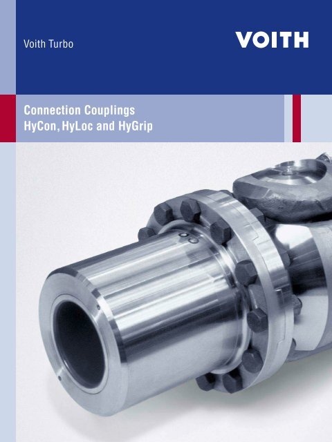
<strong>Connection</strong> <strong>Couplings</strong><br />
<strong>HyCon</strong>, <strong>HyLoc</strong> <strong>and</strong> <strong>HyGrip</strong>
<strong>Voith</strong> <strong>Turbo</strong> Safeset<br />
We are the experts in torque-limiting <strong>and</strong> connection couplings at <strong>Voith</strong> <strong>Turbo</strong>.<br />
<strong>Voith</strong> <strong>Turbo</strong>, the specialist for hydrodynamic drive, coupling <strong>and</strong> braking systems for road,<br />
rail <strong>and</strong> industrial applications, as well as for ship propulsion systems, is a Group Division<br />
of <strong>Voith</strong> AG.<br />
<strong>Voith</strong> is one of the largest family-owned companies in Europe with a workforce of around<br />
39,000, EUR 5.1 billion in sales in the 2008/2009 fiscal year <strong>and</strong> 280 sites worldwide. The<br />
company is active in the energy, oil <strong>and</strong> gas, paper <strong>and</strong> raw materials as well as transportation<br />
<strong>and</strong> automotive markets around the world.
Principle<br />
<strong>HyCon</strong>, <strong>HyLoc</strong> <strong>and</strong> <strong>HyGrip</strong><br />
<strong>Voith</strong> connection couplings provide a backlash-free, frictional,<br />
quick setting/releasing shaft-hub connections. The setting or<br />
releasing occurs hydraulically. Depending on the application,<br />
various operating principles are available, all of which offer the<br />
advantage of a backlash-free pressure connection.<br />
<strong>HyCon</strong> <strong>HyLoc</strong> <strong>HyGrip</strong><br />
n Mechanical shaft-shaft/shaft-flange<br />
connection<br />
n Hydraulically set <strong>and</strong> released<br />
n Oil pressure is not required for<br />
transmitting torque<br />
By hydraulically pushing a tapered outer<br />
sleeve upon a tapered inner sleeve, a radial<br />
force is created. Subsequently a frictional<br />
connection is created between shaft,<br />
coupling <strong>and</strong> shaft/flange.<br />
During setting <strong>and</strong> releasing, the shaft hub<br />
remains static, only the tapered outer sleeve<br />
is moved.<br />
n Mechanical shaft-hub connection<br />
n Hydraulically set <strong>and</strong> released<br />
n Oil pressure is not required for<br />
transmitting torque<br />
By hydraulically pushing a tapered sleeve<br />
inside a coupling unit, a radial force is<br />
created. Subsequently a frictional<br />
connection is created between shaft,<br />
coupling <strong>and</strong> hub.<br />
During setting <strong>and</strong> releasing, the shaft<br />
hub remains static, only the tapered con-<br />
ical sleeve inside the coupling moves.<br />
n Hydraulic hollow sleeve-shaft-hub<br />
connection<br />
n Pumped up hydraulically<br />
n Oil pressure is required for transmitting<br />
torque<br />
By hydraulically exp<strong>and</strong>ing a coupling unit, a<br />
radial force is created. Subsequently a<br />
frictional connection is created between<br />
shaft, coupling <strong>and</strong> hub.<br />
During setting <strong>and</strong> releasing, the shaft hub<br />
remains static.<br />
<strong>Voith</strong> <strong>Turbo</strong> I <strong>Connection</strong> <strong>Couplings</strong> <strong>HyCon</strong>, <strong>HyLoc</strong> <strong>and</strong> <strong>HyGrip</strong> I G 1578 en 3
4<br />
Connecting applications<br />
<strong>HyCon</strong>, <strong>HyLoc</strong> <strong>and</strong> <strong>HyGrip</strong><br />
Marine: propulsion shafts <strong>and</strong> drive line components Navy: propulsion shafts <strong>and</strong> drive line components<br />
Metal processing: roll connections, slitting equipment, grinding shafts <strong>and</strong><br />
drive train components<br />
<strong>Voith</strong> <strong>Turbo</strong> I <strong>Connection</strong> <strong>Couplings</strong> <strong>HyCon</strong>, <strong>HyLoc</strong> <strong>and</strong> <strong>HyGrip</strong> I G 1578 en<br />
Power generation: driveline components
Mining: driveline components<br />
<strong>Voith</strong> <strong>Turbo</strong> I <strong>Connection</strong> <strong>Couplings</strong> <strong>HyCon</strong>, <strong>HyLoc</strong> <strong>and</strong> <strong>HyGrip</strong> I G 1578 en 5
6<br />
<strong>HyCon</strong><br />
A breakthrough in connection technology<br />
The coupling friction surfaces are trea ted with a unique process, which more than<br />
doubles the friction factor. This gives the corresponding increase of the transmittable<br />
torque.<br />
After a careful investigation DNV <strong>and</strong> ABS has type approved the <strong>HyCon</strong> coupling for<br />
marine applications using a calculation value of m = 0.3 on the friction coef fi cient. The<br />
corresponding value for conventional friction joints is m = 0.14.<br />
with HFC<br />
without HFC<br />
Comparison of <strong>HyCon</strong> with <strong>and</strong> without HFC coating: 50% reduction of friction length or pressure<br />
<strong>Voith</strong> <strong>Turbo</strong> I <strong>Connection</strong> <strong>Couplings</strong> <strong>HyCon</strong>, <strong>HyLoc</strong> <strong>and</strong> <strong>HyGrip</strong> I G 1578 en<br />
<strong>HyCon</strong>-F <strong>and</strong> <strong>HyCon</strong>-S with high friction coating (HFC), approved by DNV <strong>and</strong> ABS<br />
0.5 x L<br />
L<br />
Torque in kNm<br />
100<br />
50<br />
with HFC coating m = 0.3<br />
without HFC coating m = 0.14<br />
50<br />
Pressure in MPa<br />
100
Setting <strong>and</strong> releasing<br />
4. Release<br />
Pump<br />
P 1<br />
P 2<br />
A R<br />
1. Depressurized<br />
3. Ready for operation<br />
1. Shaft is removed or pushed into correct axial position.<br />
2. Connect both hydraulic hoses to hydraulic fittings “P1”<br />
<strong>and</strong> “P2”. Activate the pump. With increasing pressure,<br />
the hub moves in the direction of the arrow. Once the set<br />
pressure is reached (approximately 1000 bar) open the<br />
valve “R” <strong>and</strong> the relief valve at the pump. It is now safe<br />
to remove the hydraulic hoses.<br />
M<br />
2. Pressurising<br />
Pump<br />
3. <strong>HyCon</strong> is now set without any internal oil pressure.<br />
4. Connect both hydraulic hoses again to “P1” <strong>and</strong> “P2”.<br />
Open valve “A” <strong>and</strong> close valve “R”. Activate the pump<br />
until a pressure of approximately 400 bar is achieved,<br />
then close valve “A”. Carry on pumping until the hub releases<br />
which results in a slight pressure increase at the<br />
gauge “M”. Slowly open valve “R”. The hub returns back<br />
to its original position. It is now safe to remove the hydraulic<br />
hoses.<br />
<strong>Voith</strong> <strong>Turbo</strong> I <strong>Connection</strong> <strong>Couplings</strong> <strong>HyCon</strong>, <strong>HyLoc</strong> <strong>and</strong> <strong>HyGrip</strong> I G 1578 en 7<br />
P 1<br />
P 2<br />
A R<br />
M
8<br />
<strong>HyCon</strong><br />
F/FX <strong>and</strong> S/SX series<br />
<strong>HyCon</strong> type F/FX<br />
Design <strong>and</strong> function<br />
The <strong>HyCon</strong> connection coupling consists mainly<br />
of a tapered sleeve <strong>and</strong> a tapered hub. By means<br />
of a sealed piston sleeve, a piston space is created<br />
which exerts hydraulic axial forces on the<br />
hub when pressure is applied. Consequently, the<br />
hub is pushed up the taper of the sleeve, which<br />
results in a radial compression. In order to carry<br />
out this process at minimum pressure <strong>and</strong> without<br />
wear, the surface of the taper is lubri cated<br />
with pressurised oil. The surface of the taper is<br />
sealed on both sides, thus no leakage can occur.<br />
In order to release the connection, oil is pumped<br />
in between the tapered surfaces until they are<br />
separated <strong>and</strong> the sleeve is moved down by the<br />
axial forces generated.<br />
<strong>Voith</strong> <strong>Turbo</strong> I <strong>Connection</strong> <strong>Couplings</strong> <strong>HyCon</strong>, <strong>HyLoc</strong> <strong>and</strong> <strong>HyGrip</strong> I G 1578 en<br />
Typical applications<br />
n Marine: Connect shaft sections in conventional<br />
propulsion drive lines<br />
n Marine: Connect drive lines to waterjets,<br />
thrusters etc.<br />
n Industrial: Connect drive shafts in heavy<br />
industry
Feature Benefits<br />
High torque capacity due to high friction coating (HFC) n Ideally suited for thin hollowed shafts<br />
n No internal reinforcement sleeves necessary<br />
Low weight n Reduced system weight<br />
n Increased effective load especially in ships <strong>and</strong> boats<br />
n Excellent resistance against shock loads in the driveline<br />
Low mass moment of inertia n Reduced system vibrations<br />
F/FX: Flange connection on inner sleeve n Simple positioning of the coupling<br />
n <strong>Connection</strong> bolts can be tightened before pressurizing of the coupling<br />
S/SX: Shaft to shaft connection n Low hydrodynamic resistance when located outboard in ships <strong>and</strong><br />
boats<br />
Industrial application designs<br />
ø 315<br />
Cold rolling mill, <strong>HyCon</strong> F315 installed between roll <strong>and</strong><br />
universal joint<br />
ø 630<br />
Hot plate mill, <strong>HyCon</strong> SX630 installed between motor <strong>and</strong> intermediate<br />
shaft on a twin drive arrangement (design torque 4200 kNm)<br />
<strong>Voith</strong> <strong>Turbo</strong> I <strong>Connection</strong> <strong>Couplings</strong> <strong>HyCon</strong>, <strong>HyLoc</strong> <strong>and</strong> <strong>HyGrip</strong> I G 1578 en 9
10<br />
<strong>HyLoc</strong><br />
5<br />
1<br />
4<br />
3<br />
2<br />
<strong>HyLoc</strong> type HC-B<br />
Design <strong>and</strong> function<br />
The <strong>HyLoc</strong> connection coupling consists of a hollow<br />
sleeve, where the internal chamber is a conical<br />
ring piston that is moved hydraulically. The<br />
ensuing radial expansion produces a backlashfree<br />
connection between a shaft <strong>and</strong> a hub.<br />
The pres sure required for assembly is normally<br />
1000 bar. A maximum of 1200 bar is usually required<br />
for disassembly. After assembly, the oil is<br />
drained, so that there is no residual oil pressure<br />
in the coupling during operation. The same applies<br />
for disassembly. The ring piston is provided<br />
with specially arranged lubrication grooves,<br />
hence a lubricating film is created when the ring<br />
piston moves between the working surfaces.<br />
<strong>Voith</strong> <strong>Turbo</strong> I <strong>Connection</strong> <strong>Couplings</strong> <strong>HyCon</strong>, <strong>HyLoc</strong> <strong>and</strong> <strong>HyGrip</strong> I G 1578 en<br />
1 Shaft<br />
2 Hub<br />
3 Hollow sleeve<br />
4 Conical ring piston<br />
5 Sealing valve/pump hose connection<br />
Typical applications<br />
n Industrial: Fixing of straightening <strong>and</strong> cutting<br />
rolls in the steel industry<br />
n Industrial: Fixing of different hubs <strong>and</strong> runners<br />
as flywheels, turbines etc.<br />
n Industrial: Knife/blade holders for rotating<br />
sitters to cut sheet metal or paper<br />
n Industrial: Blade holders for cutting thick sheet<br />
metals, e.g. in wide strip hot rolling mills<br />
<strong>HyLoc</strong> disc knife holder type HC-B
Feature Benefits<br />
Backlash-free connection n Improved control of processes<br />
n Increased service life of all driveline components<br />
n No notch effects as the keyways are eliminated<br />
Design optimized for simple assembly <strong>and</strong> disassembly n Rapid <strong>and</strong> accurate installation<br />
Minimized radial <strong>and</strong> axial run out n Improved control of actual process<br />
Design optimized for withst<strong>and</strong>ing high radial forces n Ideally suited for roll connections<br />
Robust design n Able to withst<strong>and</strong> dirty <strong>and</strong> difficult environments<br />
High friction coating (HFC) optional n Extremely high torque capacity<br />
ON OFF<br />
<strong>Connection</strong> of the hydraulic pump<br />
ON: setting/pressurizing<br />
OFF: releasing/depresurizing<br />
<strong>Voith</strong> <strong>Turbo</strong> I <strong>Connection</strong> <strong>Couplings</strong> <strong>HyCon</strong>, <strong>HyLoc</strong> <strong>and</strong> <strong>HyGrip</strong> I G 1578 en 11
12<br />
<strong>HyGrip</strong><br />
5<br />
4<br />
1<br />
3<br />
2<br />
<strong>HyGrip</strong> type HG-B<br />
Design <strong>and</strong> function<br />
The <strong>HyGrip</strong> connection coupling consists of a<br />
twin-walled pressure sleeve. It is pressurized<br />
with oil to 1200 bar <strong>and</strong> sealed with a brass<br />
valve. This results in a completely backlash-free<br />
frictional connection.<br />
<strong>HyGrip</strong> connection couplings can be specifically<br />
designed to meet the exact requirements of the<br />
application.<br />
The torque transmission capacity <strong>and</strong> the axial<br />
forces are proportional to the oil pressure. The<br />
connection can be set <strong>and</strong> released very quickly<br />
if a suitable hydraulic pump is used.<br />
<strong>Voith</strong> <strong>Turbo</strong> I <strong>Connection</strong> <strong>Couplings</strong> <strong>HyCon</strong>, <strong>HyLoc</strong> <strong>and</strong> <strong>HyGrip</strong> I G 1578 en<br />
1 Shaft<br />
2 Hub<br />
3 Hollow sleeve<br />
4 Pump hose connection<br />
5 Sealing valve<br />
Typical applications<br />
n Industrial: Fixing of straightening rolls <strong>and</strong><br />
cutting rolls where the radial forces are low<br />
n Industrial: Fixing of flexible drive shafts <strong>and</strong><br />
couplings for easy assembly <strong>and</strong> disassembly<br />
n Industrial: Knife/blade holders for rotating<br />
slitters to cut sheet metal or paper<br />
<strong>HyGrip</strong> disc knife holder type HG-B
Feature Benefits<br />
Backlash-free connection n Improved control of processes<br />
n Increased service life of all driveline components<br />
n No notch effects as the keyways are eliminated<br />
Design optimized for simple assembly <strong>and</strong> disassembly n Rapid <strong>and</strong> accurate installation<br />
Minimized radial <strong>and</strong> axial run out n Improved control of actual process<br />
Robust design n Able to withst<strong>and</strong> dirty <strong>and</strong> difficult environments<br />
High friction coating (HFC) optional n Extremely high torque capacity<br />
Various Applications<br />
a b<br />
<strong>HyGrip</strong> type HG-N <strong>HyGrip</strong> type HG-W <strong>HyGrip</strong> type HG-F<br />
a) shaft with round journal<br />
b) shaft with flat journal<br />
<strong>Voith</strong> <strong>Turbo</strong> I <strong>Connection</strong> <strong>Couplings</strong> <strong>HyCon</strong>, <strong>HyLoc</strong> <strong>and</strong> <strong>HyGrip</strong> I G 1578 en 13
14<br />
<strong>HyCon</strong> F <strong>HyCon</strong> FX<br />
Size<br />
Technical Data<br />
<strong>HyCon</strong> F <strong>and</strong> FX series<br />
ø D f<br />
T<br />
[kNm]<br />
D 1<br />
[mm]<br />
D 2<br />
[mm]<br />
D f<br />
[mm]<br />
DD1<br />
[mm]<br />
L 1<br />
[mm]<br />
L 2<br />
[mm]<br />
<strong>Voith</strong> <strong>Turbo</strong> I <strong>Connection</strong> <strong>Couplings</strong> <strong>HyCon</strong>, <strong>HyLoc</strong> <strong>and</strong> <strong>HyGrip</strong> I G 1578 en<br />
L 1<br />
L 2<br />
tolerance h7 or to customer dem<strong>and</strong><br />
m<br />
[kg]<br />
J<br />
[kgm 2 ]<br />
Size<br />
T<br />
[kNm]<br />
D 1<br />
[mm]<br />
D 2<br />
[mm]<br />
D f<br />
[mm]<br />
DD1<br />
[mm]<br />
L 1<br />
[mm]<br />
L 2<br />
[mm]<br />
m<br />
[kg]<br />
J<br />
[kgm 2 ]<br />
80 14.7 80 130 185 0.06 113 87 8 0.027 80 26.6 80 145 235 0.06 182 139 19 0.092<br />
90 21.4 90 147 210 0.06 125 95 11 0.050 90 39.1 90 164 285 0.06 202 153 29 0.201<br />
100 29.1 100 158 235 0.06 135 103 14 0.077 100 53 100 177 305 0.06 222 168 37 0.293<br />
110 38.4 110 174 260 0.08 149 114 19 0.126 110 69.7 110 194 325 0.08 243 185 47 0.432<br />
120 50.5 120 191 285 0.08 166 125 25 0.205 120 92.3 120 214 345 0.08 269 202 62 0.657<br />
130 65.3 130 207 305 0.08 176 132 31 0.294 130 120 130 233 390 0.08 289 216 82 1.093<br />
140 82.6 140 223 325 0.08 194 147 40 0.425 140 153 140 252 415 0.08 317 237 104 1.573<br />
150 102 150 240 345 0.08 205 154 49 0.597 150 191 150 270 455 0.08 336 250 130 2.344<br />
160 126 160 256 365 0.08 216 161 58 0.801 160 235 160 289 475 0.08 358 265 156 3.101<br />
170 151 170 272 390 0.085 226 168 69 1.084 170 282 170 307 495 0.085 377 278 183 4.008<br />
180 179 180 288 415 0.09 236 175 81 1.441 180 335 180 324 525 0.09 395 291 214 5.269<br />
190 211 190 303 435 0.095 247 183 93 1.836 190 393 190 343 555 0.095 416 305 253 6.973<br />
200 246 200 320 455 0.1 257 190 108 2.342 200 458 200 362 575 0.1 435 318 291 8.723<br />
220 327 220 351 495 0.11 278 204 139 3.612 220 610 220 400 620 0.11 473 344 380 13.439<br />
240 424 240 383 525 0.12 302 220 176 5.306 240 793 240 436 675 0.12 512 372 489 20.531<br />
260 540 260 416 575 0.13 322 234 224 8.028 260 1000 260 470 730 0.13 549 398 610 30.024<br />
280 674 280 448 605 0.14 344 249 272 11.056 280 1260 280 506 810 0.14 588 426 777 46.345<br />
300 830 300 480 635 0.15 365 264 327 14.942 300 1540 300 542 840 0.15 626 452 924 60.444<br />
320 1000 320 511 695 0.16 385 277 398 21.247 320 1880 320 578 890 0.16 663 478 1108 81.825<br />
340 1200 340 544 730 0.17 407 291 473 28.282 340 2250 340 614 955 0.17 701 504 1333 112.763<br />
360 1430 360 576 760 0.18 427 305 550 36.259 360 2680 360 650 1000 0.18 738 530 1560 145.829<br />
380 1680 380 607 820 0.19 447 319 651 48.860 380 3150 380 685 1040 0.19 775 556 1799 183.807<br />
400 1960 400 639 855 0.2 469 332 751 61.957 400 3670 400 721 1115 0.2 812 581 2121 246.385<br />
T: torque m: mass J: mass moment of inertia DD1: Assembly clearance shaft-bore<br />
D 1<br />
D 2
<strong>HyCon</strong> S <strong>and</strong> SX series<br />
<strong>HyCon</strong> S <strong>HyCon</strong> SX<br />
Size<br />
T<br />
[kNm]<br />
D 1<br />
[mm]<br />
D 2<br />
[mm]<br />
L 1<br />
DD1<br />
[mm]<br />
L 1<br />
[mm]<br />
L 2<br />
[mm]<br />
m<br />
[kg]<br />
J<br />
[kgm 2 ]<br />
Size<br />
T<br />
[kNm]<br />
D 1<br />
[mm]<br />
D 2<br />
[mm]<br />
DD1<br />
[mm]<br />
L 1<br />
[mm]<br />
L 2<br />
[mm]<br />
m<br />
[kg]<br />
J<br />
[kgm 2 ]<br />
80 15.6 80 125 0.06 142 51 8 0.022 80 28.7 80 136 0.06 253 102 19 0.059<br />
90 22.6 90 140 0.06 157 58 11 0.039 90 41.8 90 154 0.06 282 116 27 0.108<br />
100 31.3 100 152 0.06 173 64 14 0.058 100 58.7 100 165 0.06 311 128 33 0.154<br />
110 40.6 110 166 0.08 189 70 18 0.089 110 75.5 110 180 0.08 342 140 43 0.238<br />
120 53.5 120 181 0.08 206 76 23 0.138 120 99.5 120 197 0.08 371 152 56 0.371<br />
130 68.9 130 196 0.08 222 83 29 0.204 130 129 130 214 0.08 400 165 71 0.559<br />
140 86.5 140 212 0.08 244 89 38 0.308 140 163 140 231 0.08 435 177 91 0.826<br />
150 107 150 227 0.08 257 95 46 0.426 150 203 150 247 0.08 461 189 110 1.143<br />
160 131 160 240 0.08 272 101 54 0.558 160 248 160 264 0.08 489 201 133 1.584<br />
170 157 170 256 0.085 285 107 64 0.760 170 298 170 280 0.085 515 213 157 2.108<br />
180 187 180 272 0.09 298 113 76 1.016 180 354 180 296 0.09 541 225 184 2.763<br />
190 220 190 286 0.095 314 119 89 1.304 190 415 190 314 0.095 570 238 220 3.698<br />
200 256 200 300 0.1 327 125 101 1.638 200 485 200 330 0.1 596 250 253 4.712<br />
220 341 220 331 0.11 354 137 134 2.636 220 645 220 363 0.11 649 274 334 7.513<br />
240 443 240 360 0.12 382 149 170 3.968 240 838 240 394 0.12 703 298 423 11.259<br />
260 563 260 391 0.13 409 162 215 5.927 260 1060 260 427 0.13 757 323 536 16.728<br />
280 704 280 420 0.14 437 174 264 8.410 280 1330 280 460 0.14 811 348 666 24.143<br />
300 865 300 450 0.15 465 186 323 11.792 300 1630 300 492 0.15 864 372 810 33.623<br />
320 1050 320 479 0.16 491 198 385 15.952 320 1980 320 525 0.16 916 396 978 46.227<br />
340 1260 340 510 0.17 519 211 462 21.714 340 2380 340 558 0.17 971 421 1172 62.548<br />
360 1490 360 540 0.18 545 223 544 28.660 360 2830 360 590 0.18 1022 445 1377 82.211<br />
380 1760 380 570 0.19 571 235 635 37.276 380 3320 380 625 0.19 1074 469 1630 109.039<br />
400 2050 400 600 0.2 597 247 736 47.850 400 3870 400 655 0.2 1126 493 1868 137.510<br />
T: torque m: mass J: mass moment of inertia DD1: Assembly clearance shaft-bore<br />
L 2<br />
D 1<br />
D 2<br />
<strong>Voith</strong> <strong>Turbo</strong> I <strong>Connection</strong> <strong>Couplings</strong> <strong>HyCon</strong>, <strong>HyLoc</strong> <strong>and</strong> <strong>HyGrip</strong> I G 1578 en 15
16<br />
<strong>HyLoc</strong> HC-B series<br />
D 1<br />
<strong>HyLoc</strong><br />
Size<br />
T<br />
[Nm]<br />
F<br />
[kN]<br />
d<br />
[mm]<br />
<strong>Voith</strong> <strong>Turbo</strong> I <strong>Connection</strong> <strong>Couplings</strong> <strong>HyCon</strong>, <strong>HyLoc</strong> <strong>and</strong> <strong>HyGrip</strong> I G 1578 en<br />
D<br />
[mm]<br />
D 1<br />
[mm]<br />
L<br />
[mm]<br />
L 1<br />
[mm]<br />
DH<br />
[mm]<br />
H<br />
J<br />
[kgm 2 ·10 -3 ]<br />
50 2600 104 50 77 101 57 82 105 M8 3.3 2.4<br />
60 4600 153 60 89 113 65 90 125 M8 5.4 3.1<br />
70 7900 226 70 102 122 75 100 145 M8 8.7 4.1<br />
80 12100 303 80 115 135 85 110 160 M8 14 5.4<br />
90 17100 380 90 128 148 95 120 180 M12 23 7.0<br />
100 24200 484 100 140 160 105 130 200 M12 34 8.6<br />
110 32900 598 110 154 173 115 140 220 M12 51 11<br />
120 43200 720 120 168 186 125 150 240 M12 76 14<br />
130 53800 828 130 182 200 135 160 260 M16 110 17<br />
140 68900 984 140 196 213 145 170 280 M16 150 21<br />
150 85400 1139 150 210 227 155 180 300 M16 210 25<br />
160 104000 1300 160 224 240 165 190 320 M16 290 30<br />
180 150000 1667 180 252 267 185 210 360 M16 500 42<br />
200 206000 2060 200 280 293 205 230 400 M16 830 56<br />
220 273000 2482 220 308 320 225 250 435 M16 1300 73<br />
T: torque (without axial force)<br />
m: mass<br />
Assembly pressure: 100 MPa<br />
7 7<br />
L 1<br />
L<br />
D<br />
d<br />
OFF<br />
F: axial force (without torque)<br />
Hub/shaft tolerances: H7/h7<br />
Disassembly pressure: ~ 120 MPa<br />
Different designs are possible on request. Larger model sizes only available as special designs.<br />
2xH<br />
m<br />
[kg]<br />
J: mass moment of inertia<br />
Oil: Gear oil type 80 W
<strong>HyGrip</strong> HG-B series<br />
<strong>HyGrip</strong>-B<br />
Size<br />
D 3<br />
T<br />
[kNm]<br />
F ax<br />
[kN]<br />
L 2<br />
L 1<br />
D 1<br />
[mm]<br />
D1 D2 D 2<br />
[mm]<br />
30 0.6 40 30 40 85 36 66 1.33 0.001<br />
35 0.9 51 35 45 91 41 71 1.5 0.002<br />
40 1.3 65 40 52 96 47 77 1.7 0.002<br />
45 1.7 75 45 58 103 53 83 2.0 0.003<br />
50 2.2 88 50 65 109 57 87 2.4 0.004<br />
60 3.6 120 60 75 120 65 95 2.8 0.005<br />
70 6.0 171 70 90 135 74 104 3.9 0.010<br />
80 7.8 195 80 100 144 90 120 4.7 0.013<br />
90 10.0 222 90 110 155 102 132 5.5 0.018<br />
100 15.0 300 100 125 170 108 146 8.2 0.034<br />
110 20.0 363 110 140 188 109 144 10.0 0.050<br />
120 25.0 416 120 150 196 133 171 12.2 0.068<br />
130 33.0 507 130 160 205 144 182 13.6 0.084<br />
140 40.0 571 140 170 215 152 190 15.0 0.104<br />
150 46.0 613 150 180 225 162 200 16.5 0.128<br />
160 71.0 887 160 200 233 180 225 24.0 0.211<br />
170 78.0 917 170 210 243 176 221 24.9 0.243<br />
180 85.0 944 180 225 261 176 221 29.7 0.330<br />
190 120.0 1263 190 240 273 222 270 40.0 0.491<br />
200 130.0 1300 200 250 283 222 270 42.0 0.560<br />
220 160.0 1454 220 270 301 222 270 45.0 0.710<br />
D 3<br />
[mm]<br />
L 1<br />
[mm]<br />
T: torque m: Mass J: Mass moment of inertia F ax: Axial force<br />
L 2<br />
[mm]<br />
If torque T <strong>and</strong> axial force Fax are transmitted simul taneously, a resulting force Fres is to be calculated.<br />
The latter must not exceed the indicated axial force Fax: Fres = √<br />
The maximum operating loads must not exceed the indicated values. An adequate safety factor should be adhered to.<br />
___________<br />
F 2<br />
a x + _____ T · 2000 ( D ) 1<br />
2<br />
Hydraulic setting sleeve for the connection of a hub<br />
with a shaft<br />
m<br />
[kg]<br />
J<br />
[kgm 2 ]<br />
<strong>Voith</strong> <strong>Turbo</strong> I <strong>Connection</strong> <strong>Couplings</strong> <strong>HyCon</strong>, <strong>HyLoc</strong> <strong>and</strong> <strong>HyGrip</strong> I G 1578 en 17
18<br />
Accessories<br />
<strong>HyCon</strong>, <strong>HyLoc</strong> <strong>and</strong> <strong>HyGrip</strong><br />
Service Boxes for <strong>HyCon</strong> Service Box for <strong>HyLoc</strong><br />
Pumps<br />
Pumps for pressurizing the couplings are available<br />
for all couplings. The size of the pump is<br />
dependent on the size of the connection coupling.<br />
Available pumps:<br />
n P115 series for coupling size 30 to 220<br />
n P240 series for coupling size 200 to 360<br />
n P700 series for coupling sizes above 360<br />
The P115 <strong>and</strong> 240 are manually operated<br />
pumps, <strong>and</strong> the P700 is pneumatically operated.<br />
For special dem<strong>and</strong>s electrically driven<br />
pumps <strong>and</strong> custom solutions are available.<br />
<strong>Voith</strong> <strong>Turbo</strong> I <strong>Connection</strong> <strong>Couplings</strong> <strong>HyCon</strong>, <strong>HyLoc</strong> <strong>and</strong> <strong>HyGrip</strong> I G 1578 en<br />
Service Boxes<br />
All operations of the couplings require some additional<br />
tools <strong>and</strong> equipment. The service boxes<br />
include all necessary tools to operate any coupling<br />
in the connection coupling range. They are<br />
also adapted for <strong>HyLoc</strong>, <strong>HyCon</strong> or <strong>HyGrip</strong> connection<br />
couplings.<br />
Stroke<br />
<strong>HyGrip</strong> pressure indicator “type 1”
Service Boxes for <strong>HyGrip</strong><br />
Pressure indicator <strong>and</strong> leakage detector<br />
Additionally, in order to monitor its function, a<br />
<strong>HyGrip</strong> coupling can be fitted with a pressure<br />
indicator, or a leakage detector.<br />
The pressure indicator reacts to internal pressure,<br />
whilst the leakage detector reacts when an<br />
oil leak appears at the pressure valve. In the<br />
event of oil loss, in both components a plate<br />
moves radially which can be sensed externally.<br />
Stroke<br />
<strong>HyGrip</strong> pressure indicator “type 2”<br />
M 14 x 1.5<br />
<strong>HyGrip</strong> sealing valves<br />
Sealing valves for Hygrip<br />
The number of sealing valves is dependent on<br />
the coupling size.<br />
L 28 L 39 L 63 L 39 B L 63 B<br />
25<br />
M 14 x 1.5<br />
36.5<br />
M 20 x 1.5<br />
55<br />
M 14 x 1.5<br />
37.5<br />
M 20 x 1.5<br />
56.5<br />
<strong>Voith</strong> <strong>Turbo</strong> I <strong>Connection</strong> <strong>Couplings</strong> <strong>HyCon</strong>, <strong>HyLoc</strong> <strong>and</strong> <strong>HyGrip</strong> I G 1578 en 19
<strong>Voith</strong> <strong>Turbo</strong> Safeset AB<br />
Rönningevägen 8<br />
824 34 Hudiksvall, Sweden<br />
Tel. +46 650 540-150<br />
Fax +46 650 540-165<br />
info.safeset@voith.com<br />
www.voithturbo.com/<br />
safeset-safety-couplings<br />
G1578en, S&F, 09.2010, 0. Dimensions <strong>and</strong> illustrations without obligation. Subject to modifications.