IPV Catalog ? High-pressure Internal Gear Pumps - Voith Turbo
IPV Catalog ? High-pressure Internal Gear Pumps - Voith Turbo
IPV Catalog ? High-pressure Internal Gear Pumps - Voith Turbo

You also want an ePaper? Increase the reach of your titles
YUMPU automatically turns print PDFs into web optimized ePapers that Google loves.
<strong>IPV</strong> <strong>Catalog</strong><br />
<strong>High</strong>-<strong>pressure</strong> <strong>Internal</strong> <strong>Gear</strong> <strong>Pumps</strong><br />
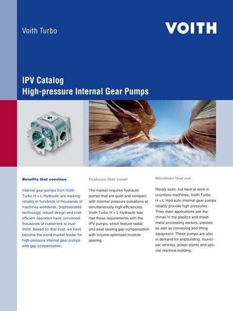
Benefits that convince<br />
<strong>Internal</strong> gear pumps from <strong>Voith</strong><br />
<strong>Turbo</strong> H + L Hydraulic are working<br />
reliably in hun dreds of thousands of<br />
machines worldwide. Sophisticated<br />
technol ogy, robust design and costefficient<br />
operation have convinced<br />
thou sands of customers to trust<br />
<strong>Voith</strong>. Based on that trust, we have<br />
be come the world market leader for<br />
high-<strong>pressure</strong> inter nal gear pumps<br />
with gap compensation.<br />
Features that count<br />
The market requires hydraulic<br />
pumps that are quiet and compact<br />
with min imal <strong>pressure</strong> pulsations at<br />
simultaneously high efficiencies.<br />
<strong>Voith</strong> <strong>Turbo</strong> H + L Hydraulic has<br />
met these require ments with the<br />
<strong>IPV</strong> pumps, which feature radial<br />
and axial sealing gap compensation<br />
with volume-opti mized involute<br />
gearing.<br />
Machines that run<br />
Rarely seen, but hard at work in<br />
countless machines, <strong>Voith</strong> <strong>Turbo</strong><br />
H + L Hydraulic in ternal gear pumps<br />
reliably provide high <strong>pressure</strong>s.<br />
Their main applica tions are machines<br />
in the plastics and sheetmetal<br />
processing sectors, presses<br />
as well as conveying and lifting<br />
equipment. These pumps are also<br />
in demand for shipbuilding, municipal<br />
vehicles, power plants and special<br />
machine building.
2<br />
Contents<br />
Design and function 3<br />
Performance data 4<br />
<strong>IPV</strong> 3 6<br />
<strong>IPV</strong> 4 8<br />
<strong>IPV</strong> 5 10<br />
<strong>IPV</strong> 6 12<br />
<strong>IPV</strong> 7 14<br />
SAE suction and <strong>pressure</strong> flanges 16<br />
Type code 17<br />
Order designation<br />
Multi-flow pumps 18<br />
Pump combinations<br />
Designs 19<br />
<strong>Voith</strong> <strong>Turbo</strong> | <strong>IPV</strong> <strong>Catalog</strong> | G 1485 en<br />
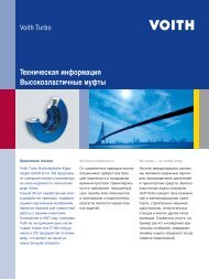
Die casting machine, pump with<br />
variable flow by speed control
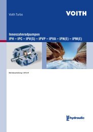
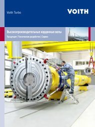
Design and Function<br />
1 7 6 5 9 2 5 6 7 10 8 2 1 9 4a 4b 3<br />
Design features<br />
<strong>Internal</strong> gear principle<br />
Sleeve bearing<br />
Radial and axial sealing gap<br />
compensation<br />
Volume-optimized involute<br />
gearing<br />
Product characteristics<br />
Long life<br />
<strong>High</strong> volume efficiency<br />
<strong>High</strong> overall efficiency<br />
Very low pump flow and <strong>pressure</strong><br />
pulsation<br />
Low noise level<br />
Compact dimensions<br />
Low weight<br />
Large speed range<br />
Very good suction properties<br />
<strong>High</strong> allowed viscosity<br />
Simple maintenance<br />
Multiple pumps and pump<br />
combinations are possible<br />
Suitable for variable-speed drives<br />
(variable volume flow!)<br />
Motor operation possible<br />
(energy recovery!)<br />
<strong>Voith</strong> <strong>Turbo</strong> | <strong>IPV</strong> <strong>Catalog</strong> | G 1485 en<br />
Function<br />
Rotation of the gears within the<br />
pump draws in the <strong>pressure</strong> fluid<br />
(usually hydraulic oil) into the space<br />
between the pinion and internal<br />
gear. The two smooth running gears<br />
help to ensure excellent intake<br />
behaviour.<br />
In the radial direction, the gear<br />
chambers are closed by gear meshing<br />
and the filler piece. In the axial<br />
direction, the axial plates seal the<br />
<strong>pressure</strong> chamber with the minimal<br />
possible gap. This design minimizes<br />
volume losses and increases efficiency.<br />
When the gears rotate, the tooth<br />
heads enter the gaps between teeth<br />
and displace the <strong>pressure</strong> fluid.<br />
1 Pinion shaft<br />
2 <strong>Internal</strong> gear<br />
3 Filler pin<br />
4a Filler segment carrier<br />
4b Filler sealing segment<br />
5 Axial disc<br />
6 Axial <strong>pressure</strong> area<br />
7 Plain bearings<br />
8 Housing<br />
9 Hydrostatic bearing<br />
10 End cover with bleeder screw<br />
■ Suction chamber<br />
■ Pressure chamber<br />
Combinations<br />
<strong>IPV</strong> pumps can be combined to form<br />
dual or multi-flow pumps.<br />
Combinations with other <strong>Voith</strong> <strong>Turbo</strong><br />
H + L Hydraulic pump series are<br />
also possible. Used in conjunction<br />
with pumps from the medium and<br />
low-<strong>pressure</strong> series, <strong>Voith</strong> equipment<br />
can handle a wide range of<br />
potential applications.<br />
For further information on possible<br />
combinations, refer to page 9 and<br />
brochure G1714 (<strong>Voith</strong> multi-flow<br />
pumps).<br />
Combinations with third-party products<br />
are generally possible. We‘ll be<br />
happy to discuss your needs.<br />
Variable volume flow<br />
We supply complete hydraulic units<br />
with <strong>IPV</strong> pumps, asynchronous motors<br />
and frequency converters (EPA/<br />
EPAF system) to generate variable<br />
volume flows. For further information,<br />
refer to our brochure G1420<br />
(<strong>Voith</strong> EPA system).<br />
3
4<br />
Performance data<br />
Technical data Calculations<br />
Design <strong>Internal</strong> gear pump with radial and axial sealing Pump flow Q = Vg th • n • ηv • 10<br />
gap compensation<br />
-3 [l/min]<br />
Power P = Q • Δp Type <strong>IPV</strong><br />
[kW]<br />
600 • ηg Mounting types SAE hole flange; ISO 3019/1 or<br />
Vg th<br />
Pump volume per revolution [cm<br />
VDMA hole flange; ISO 3019/2<br />
3 ]<br />
n Speed [min-1 ]<br />
Line mounting SAE suction and <strong>pressure</strong> flange J 518 C Code 61 ηv Volumetric efficiency<br />
Sense of rotation Right or left-hand rotation ηg Overall efficiency<br />
Mounting position any Δp Differential <strong>pressure</strong> [bar]<br />
Shaft load For details of radial and axial drive shaft loads<br />
please contact your <strong>Voith</strong> <strong>Turbo</strong> H + L Hydraulic<br />
representative<br />
Input <strong>pressure</strong> 0,6…3 bar absolute <strong>pressure</strong><br />
Pressure fluid HLP mineral oils DIN 51524, part 2 or 3<br />
Viscosity range of the <strong>pressure</strong> fluid 10…100 mm2s-1 (cSt)<br />
Permissible start viscosity max. 2000 mm2s-1 (cSt)<br />
Permissible temperature of the <strong>pressure</strong><br />
fluid<br />
Required purity of the <strong>pressure</strong> fluid<br />
according to NAS 1638<br />
-20…+80 °C<br />
Class 8<br />
Filtration Filtration quotient min. β 20 ≥ 75,<br />
recommended β 10 ≥ 100 (longer life)<br />
Permissible ambient temperature -10…+60 °C<br />
<strong>Voith</strong> <strong>Turbo</strong> | <strong>IPV</strong> <strong>Catalog</strong> | G 1485 en
Characteristics<br />
Type,<br />
size-delivery<br />
Displacement per<br />
revolution<br />
Speed Delivery Pressures<br />
min. max. at 1.500 rpm Continuous Peak at<br />
1.500 rpm<br />
Peak at<br />
n max<br />
[cm 3 ] [min -1 ] [min -1 ] [l/min] [bar] [bar] [bar]<br />
<strong>IPV</strong> 3 – 3.5 3.6 400 3,600 5.4 330 345 345<br />
<strong>IPV</strong> 3 – 5 5.2 400 3,600 7.8 330 345 345<br />
<strong>IPV</strong> 3 – 6.3 6.4 400 3,600 9.6 330 345 345<br />
<strong>IPV</strong> 3 – 8 8.2 400 3,600 12.3 330 345 345<br />
<strong>IPV</strong> 3 – 10 10.2 400 3,600 15.3 330 345 345<br />
<strong>IPV</strong> 4 – 13 13.3 400 3,600 19.9 330 345 345<br />
<strong>IPV</strong> 4 – 16 15.8 400 3,400 23.7 330 345 345<br />
<strong>IPV</strong> 4 – 20 20.7 400 3,200 31.0 330 345 345<br />
<strong>IPV</strong> 4 – 25 25.4 400 3,000 38.1 300 330 330<br />
<strong>IPV</strong> 4 – 32 32.6 400 2,800 48.9 250 280 280<br />
<strong>IPV</strong> 5 – 32 33.1 400 3,000 49.6 315 345 315<br />
<strong>IPV</strong> 5 – 40 41.0 400 2,800 61.5 315 345 315<br />
<strong>IPV</strong> 5 – 50 50.3 400 2,500 75.4 280 315 280<br />
<strong>IPV</strong> 5 – 64 64.9 400 2,200 97.3 230 250 250<br />
<strong>IPV</strong> 6 – 64 64.1 400 2,600 96.1 300 330 300<br />
<strong>IPV</strong> 6 – 80 80.7 400 2,400 121.0 280 315 280<br />
<strong>IPV</strong> 6 – 100 101.3 400 2,100 151.9 250 300 270<br />
<strong>IPV</strong> 6 – 125 126.2 400 1,800 189.3 210 250 250<br />
<strong>IPV</strong> 7 – 125 125.8 400 2,200 188.7 300 330 300<br />
<strong>IPV</strong> 7 – 160 160.8 400 2,000 241.2 280 315 280<br />
<strong>IPV</strong> 7 – 200 202.7 400 1,800 304.0 250 300 270<br />
<strong>IPV</strong> 7 – 250 251.7 400 1,800 377.5 210 250 250<br />
The values given apply for:<br />
Pumping of mineral oils with a<br />
viscosity of 20…40 mm2s-1 An input <strong>pressure</strong> of 0.8…3.0 bar<br />
absolute<br />
<strong>Voith</strong> <strong>Turbo</strong> | <strong>IPV</strong> <strong>Catalog</strong> | G 1485 en<br />
Notes:<br />
Peak <strong>pressure</strong>s apply for 15% of<br />
operating time with a maximum<br />
cycle time of 1 minute.<br />
Please inquire about peak <strong>pressure</strong>s<br />
at non-standard speeds.<br />
Due to production tolerances, the<br />
pump volume may be reduced by<br />
up to 1.5%.<br />
5
6<br />
<strong>IPV</strong> 3<br />
Standard Design<br />
Design and dimensions<br />
47 53<br />
51 43<br />
6h9<br />
ø18h7<br />
20.5<br />
12<br />
6<br />
35<br />
43<br />
r c/2 c/2<br />
19.5<br />
v<br />
g<br />
w<br />
c e<br />
* Ensure the M10x1plug screw, hexagon socket SW5, is tightened to a torque of 10 Nm during pumping operation.<br />
Dependent on the pump position, filling or ventilation is possible here prior to commissioning.<br />
Design Dimensions SAE flange no.<br />
5,8<br />
*<br />
11<br />
k<br />
l<br />
M5<br />
*<br />
132<br />
106.4<br />
c e g h i k l r v w Weight<br />
[mm] [mm] [mm] [mm] [mm] [mm] Thread [mm] [mm] Thread [kg]<br />
<strong>IPV</strong> 3 – 3.5 66 20.5 9 14 38.1 17.5 M8x13 38.1 17.5 M8x13 4.0 10 10<br />
<strong>IPV</strong> 3 – 5 70 20.5 11 14 38.1 17.5 M8x13 38.1 17.5 M8x13 4.2 10 10<br />
<strong>IPV</strong> 3 – 6.3 73 20.5 11 19 47.5 22 M10x15 38.1 17.5 M8x13 4.4 10 11<br />
<strong>IPV</strong> 3 – 8 77.5 20.5 13 19 47.5 22 M10x15 38.1 17.5 M8x13 4.6 10 11<br />
<strong>IPV</strong> 3 – 10 82.5 20.5 13 21 52.4 26.2 M10x15 38.1 17.5 M8x13 4.8 10 12<br />
A B<br />
<strong>Voith</strong> <strong>Turbo</strong> | <strong>IPV</strong> <strong>Catalog</strong> | G 1485 en<br />
Allowed input torques:<br />
Input shaft A: 160 Nm<br />
Secondary shaft B: 80 Nm<br />
Delivery Q Efficiency v and g<br />
Delivery Q [l/min]<br />
20<br />
15<br />
10<br />
5<br />
Efficiency [%]<br />
0<br />
0 50 100 150 200 250 300 350<br />
70<br />
0 50 100 150 200 250 300 350<br />
Operating <strong>pressure</strong> p [bar] Operating <strong>pressure</strong> p [bar]<br />
100<br />
95<br />
90<br />
85<br />
80<br />
75<br />
h<br />
i<br />
g<br />
ø82.55h8<br />
v
Type Pump sizes Rotation, suction connection Mounting fl ange Shaft end<br />
<strong>IPV</strong> 3 3.5<br />
5<br />
6.3<br />
8<br />
10<br />
Standard<br />
Clockwise rotation,<br />
radial suction port<br />
Variants<br />
Anti-clockwise rotation,<br />
radial suction port<br />
SAE 2-hole fl ange, dimensions on left Parallel shaft with keyway connection,<br />
dimensions on left<br />
1 0 1<br />
43 19.5<br />
Involute gearing with<br />
SAE 2-hole fl ange<br />
6 30 0<br />
VDMA 2-hole fl ange<br />
ø80 h8<br />
12<br />
7<br />
36 19.5<br />
Designation according to type code Type code/order designation, see page 17<br />
11<br />
109<br />
132<br />
4<br />
ANSI B92.1a<br />
16 / 32 DP 30°<br />
Input power P Airborne noise level Measuring location 1 m axial Measurement conditions<br />
Input power P [kW]<br />
10<br />
8<br />
6<br />
4<br />
2<br />
Airborne noise level [dB(A)]<br />
0<br />
0 50 100 150 200 250 300 350<br />
40<br />
0 50 100 150 200 250 300 350<br />
Operating <strong>pressure</strong> p [bar]<br />
Operating <strong>pressure</strong> p [bar]<br />
<strong>Voith</strong> <strong>Turbo</strong> | <strong>IPV</strong> <strong>Catalog</strong> | G 1485 en<br />
60<br />
55<br />
50<br />
45<br />
Note: Measurement taken in a low-noise room.<br />
In a anechoic room, the measurements are approx. 5 dB(A) lower.<br />
5 h9<br />
ø16 h7<br />
18<br />
35<br />
43<br />
37.9<br />
28<br />
36<br />
1<br />
Speed: 1.500 rpm<br />
Viscosity of <strong>pressure</strong> fluid: 46 mm 2 s -1<br />
Operating temperature: 40 °C<br />
Characteristic curves:<br />
<strong>IPV</strong> 3 – 3.5<br />
<strong>IPV</strong> 3 – 5<br />
<strong>IPV</strong> 3 – 6.3<br />
<strong>IPV</strong> 3 – 8<br />
<strong>IPV</strong> 3 – 10<br />
7
8<br />
<strong>IPV</strong> 4<br />
Standard Design<br />
Design and dimensions<br />
57 67<br />
64 60<br />
8 h9<br />
ø25 h7<br />
28<br />
13<br />
9.5<br />
ø88<br />
48<br />
56 26<br />
v<br />
r c/2 c/2<br />
g<br />
w<br />
5,8<br />
c e<br />
* Ensure the M10x1 plug screw, hexagon socket SW5, is tightened to a torque of 10 Nm during pumping operation.<br />
Dependent on the pump position, filling or ventilation is possible here prior to commissioning.<br />
Design Dimensions SAE fl ange no.<br />
c e g h i k l r v w Weight<br />
[mm] [mm] [mm] [mm] [mm] [mm] Thread [mm] [mm] Thread [kg]<br />
<strong>IPV</strong> 4 – 13 88.5 31 13 23 52.4 26.2 M10x15 38.1 17.5 M8x13 8.6 10 12<br />
<strong>IPV</strong> 4 – 16 92.5 31 14 25 52.4 26.3 M10x15 38.1 17.5 M8x13 9.0 10 12<br />
<strong>IPV</strong> 4 – 20 98 31 18 27 58.7 30.2 M10x15 47.5 22 M10x15 9.6 11 13<br />
<strong>IPV</strong> 4 – 25 104 31 18 30 58.7 30.2 M10x15 47.5 22 M10x15 10.2 11 13<br />
<strong>IPV</strong> 4 – 32 113 31 18 32 58.7 30.2 M10x15 47.5 22 M10x15 11.0 11 13<br />
A B<br />
<strong>Voith</strong> <strong>Turbo</strong> | <strong>IPV</strong> <strong>Catalog</strong> | G 1485 en<br />
Allowed input torques:<br />
Input shaft A: 335 Nm<br />
Secondary shaft B: 190 Nm<br />
55<br />
45<br />
35<br />
25<br />
15<br />
0 50 100 150 200 250 300 350<br />
70<br />
0 50 100 150 200 250 300 350<br />
Operating <strong>pressure</strong> p [bar] Operating <strong>pressure</strong> p [bar]<br />
*<br />
6.8<br />
100<br />
95<br />
90<br />
85<br />
80<br />
75<br />
13.5<br />
k<br />
M8x19<br />
Delivery Q Effi ciency v and g<br />
Delivery Q [l/min]<br />
Effi ciency [%]<br />
l<br />
*<br />
170<br />
146<br />
h<br />
i<br />
g<br />
ø101.6 h8<br />
v
Type Pump sizes Rotation, suction connection Mounting fl ange Shaft end<br />
<strong>IPV</strong> 4 13<br />
16<br />
20<br />
25<br />
32<br />
Standard<br />
Clockwise rotation,<br />
radial suction port<br />
Variants<br />
Anti-clockwise rotation,<br />
radial suction port<br />
SAE 2-hole fl ange, dimensions on left Parallel shaft with keyway connection,<br />
dimensions on left<br />
1 26 7 48 1<br />
56<br />
Involute gearing with<br />
SAE 2-hole fl ange<br />
6 0<br />
38<br />
ANSI B92.1a<br />
16 / 32 DP 30°<br />
SAE 4-hole fl ange<br />
ø101.6 h8<br />
12<br />
6<br />
32 50<br />
ø78<br />
124<br />
VDMA 4-hole fl ange<br />
ø100.6 h8<br />
12<br />
9<br />
52.5 50<br />
Designation according to type code Type code/order designation, see page 17<br />
Input power P Airborne noise level Measuring location 1 m axial<br />
Input power P [kW]<br />
25<br />
20<br />
15<br />
10<br />
5<br />
0<br />
0 50 100 150 200 250 300 350<br />
40<br />
0 50 100 150 200 250 300 350<br />
Operating <strong>pressure</strong> p [bar]<br />
Operating <strong>pressure</strong> p [bar]<br />
<strong>Voith</strong> <strong>Turbo</strong> | <strong>IPV</strong> <strong>Catalog</strong> | G 1485 en<br />
Airborne noise level [dB(A)]<br />
60<br />
55<br />
50<br />
45<br />
Note: Measurement taken in a low-noise room.<br />
In a anechoic room, the measurements are approx. 5 dB(A) lower.<br />
90<br />
124<br />
90<br />
124<br />
13.5<br />
90<br />
11<br />
ø125<br />
1<br />
5<br />
56<br />
45.9<br />
48<br />
32<br />
42<br />
52.5<br />
Measurement conditions<br />
1<br />
1<br />
Speed: 1.500 rpm<br />
Viscosity of <strong>pressure</strong> fluid: 46 mm 2 s -1<br />
Operating temperature: 40 °C<br />
Characteristic curves:<br />
<strong>IPV</strong> 4 – 13<br />
<strong>IPV</strong> 4 – 16<br />
<strong>IPV</strong> 4 – 20<br />
<strong>IPV</strong> 4 – 25<br />
<strong>IPV</strong> 4 – 32<br />
9
10<br />
<strong>IPV</strong> 5<br />
Standard Design<br />
Design and dimensions<br />
75 83<br />
77 74<br />
10 h9<br />
ø32 h7<br />
35<br />
18<br />
6<br />
60<br />
68<br />
r c/2 c/2<br />
20<br />
v<br />
g w<br />
c e<br />
* Ensure the M10x1 plug screw, hexagon socket SW5, is tightened to a torque of 10 Nm during pumping operation.<br />
Dependent on the pump position, filling or ventilation is possible here prior to commissioning.<br />
Design Dimensions SAE fl ange no.<br />
c e g h i k l r v w Weight<br />
[mm] [mm] [mm] [mm] [mm] [mm] Thread [mm] [mm] Thread [kg]<br />
<strong>IPV</strong> 5 – 32 119 36 18 32 58.7 30.2 M10x15 47.5 22 M10x15 15.5 11 13<br />
<strong>IPV</strong> 5 – 40 125 36 19 35 70 36 M12x20 52.4 26.2 M10x15 16.3 12 30<br />
<strong>IPV</strong> 5 – 50 132 36 21 40 70 36 M12x20 52.4 26.2 M10x15 17.4 12 30<br />
<strong>IPV</strong> 5 – 64 163 36 23 40 70 36 M12x20 52.4 26.2 M10x16 18.7 12 30<br />
A B<br />
<strong>Voith</strong> <strong>Turbo</strong> | <strong>IPV</strong> <strong>Catalog</strong> | G 1485 en<br />
Allowed input torques:<br />
Input shaft A: 605 Nm<br />
Secondary shaft B: 400 Nm<br />
*<br />
8.7<br />
17.5<br />
k<br />
M12x25<br />
Delivery Q Effi ciency v and g<br />
Delivery Q [l/min]<br />
100<br />
90<br />
80<br />
70<br />
60<br />
50<br />
Effi ciency [%]<br />
40<br />
0 50 100 150 200 250 300 350<br />
70<br />
0 50 100 150 200 250 300 350<br />
Operating <strong>pressure</strong> p [bar] Operating <strong>pressure</strong> p [bar]<br />
100<br />
95<br />
90<br />
85<br />
80<br />
75<br />
l<br />
*<br />
210<br />
181<br />
h<br />
i<br />
g<br />
ø127 h8<br />
v
Type Pump sizes Rotation, suction connection Mounting fl ange Shaft end<br />
<strong>IPV</strong> 5 32<br />
40<br />
50<br />
64<br />
Standard<br />
Clockwise rotation,<br />
radial suction port<br />
Variants<br />
Anti-clockwise rotation,<br />
radial suction port<br />
SAE 2-hole fl ange, dimensions on left Parallel shaft with keyway connection,<br />
dimensions on left<br />
1<br />
20<br />
0<br />
60<br />
1<br />
68<br />
SAE 2-hole fl ange, variant Involute gearing<br />
6 7 0<br />
ø101.6 h8<br />
55.4<br />
20<br />
6<br />
SAE 4-hole fl ange<br />
16<br />
6<br />
ø127 h8<br />
35 53<br />
ca. ø100<br />
VDMA 4-hole fl ange<br />
16<br />
9<br />
ø125 h8<br />
68.5 53<br />
Designation according to type code Type code/order designation, see page 17<br />
Input power P Airborne noise level Measuring location 1 m axial<br />
Input power P [kW]<br />
50<br />
40<br />
30<br />
20<br />
10<br />
0<br />
0 50 100 150 200 250 300 350<br />
50<br />
0 50 100 150 200 250 300 350<br />
Operating <strong>pressure</strong> p [bar]<br />
Operating <strong>pressure</strong> p [bar]<br />
<strong>Voith</strong> <strong>Turbo</strong> | <strong>IPV</strong> <strong>Catalog</strong> | G 1485 en<br />
Airborne noise level [dB(A)]<br />
70<br />
65<br />
60<br />
55<br />
172<br />
146<br />
ø162<br />
ø190<br />
ø160<br />
ø190<br />
13.5<br />
17,5<br />
14<br />
1<br />
5<br />
ANSI B92.1a<br />
12 / 24 DP 30°<br />
Note: Measurement taken in a low-noise room.<br />
In a anechoic room, the measurements are approx. 5 dB(A) lower.<br />
68<br />
47.5<br />
55.4<br />
35<br />
60<br />
58<br />
68.5<br />
Measurement conditions<br />
1<br />
1<br />
Speed: 1.500 rpm<br />
Viscosity of <strong>pressure</strong> fluid: 46 mm 2 s -1<br />
Operating temperature: 40 °C<br />
Characteristic curves:<br />
<strong>IPV</strong> 5 – 32<br />
<strong>IPV</strong> 5 – 40<br />
<strong>IPV</strong> 5 – 50<br />
<strong>IPV</strong> 5 – 64<br />
11
12<br />
<strong>IPV</strong> 6<br />
Standard Design<br />
Design and dimensions<br />
95 109<br />
100 98<br />
12 h9<br />
ø40 h7<br />
43<br />
20<br />
6<br />
80<br />
88<br />
r c/2 c/2<br />
22<br />
v<br />
g<br />
w<br />
c e<br />
* Ensure the M10x1 plug screw, hexagon socket SW5, is tightened to a torque of 10 Nm during pumping operation.<br />
Dependent on the pump position, filling or ventilation is possible here prior to commissioning.<br />
Design Dimensions SAE fl ange no.<br />
c e g h i k l r v w Weight<br />
[mm] [mm] [mm] [mm] [mm] [mm] Thread [mm] [mm] Thread [kg]<br />
<strong>IPV</strong> 6 – 64 140 40 23 40 70 36 M12x20 52,4 26,2 M10x15 29,2 12 30<br />
<strong>IPV</strong> 6 – 80 148 35 23 45 77,8 42,9 M12x20 70 36 M12x20 30,7 14 15<br />
<strong>IPV</strong> 6 – 100 158 35 27 50 77,8 42,9 M12x20 70 36 M12x20 32,6 14 15<br />
<strong>IPV</strong> 6 – 125 170 40 30 50 77,8 42,9 M12x20 70 36 M10x16 35,0 14 15<br />
A B<br />
<strong>Voith</strong> <strong>Turbo</strong> | <strong>IPV</strong> <strong>Catalog</strong> | G 1485 en<br />
Allowed input torques:<br />
Input shaft A: 1,050 Nm<br />
Secondary shaft B: 780 Nm<br />
*<br />
11.2<br />
22<br />
k<br />
M12x25<br />
Delivery Q Effi ciency v and g<br />
Delivery Q [l/min]<br />
200<br />
175<br />
150<br />
125<br />
100<br />
Effi ciency [%]<br />
75<br />
0 50 100 150 200 250 300 350<br />
70<br />
0 50 100 150 200 250 300 350<br />
Operating <strong>pressure</strong> p [bar] Operating <strong>pressure</strong> p [bar]<br />
100<br />
95<br />
90<br />
85<br />
80<br />
75<br />
l<br />
264<br />
228.6<br />
*<br />
h<br />
i<br />
g<br />
ø152.4 h8<br />
v
Type Pump sizes Rotation, suction connection Mounting fl ange Shaft end<br />
<strong>IPV</strong> 6 64<br />
80<br />
100<br />
125<br />
Standard<br />
Clockwise rotation,<br />
radial suction port<br />
Variants<br />
Anti-clockwise rotation,<br />
radial suction port<br />
SAE 2-hole fl ange, dimensions on left Parallel shaft with keyway connection,<br />
dimensions on left<br />
1<br />
22<br />
0 1<br />
80<br />
88<br />
SAE 2-hole fl ange, variant Involute gearing<br />
6 7 0<br />
ø127 h8<br />
12<br />
6<br />
61.9 22<br />
SAE 4-hole fl ange<br />
ø152.4 h8<br />
20<br />
6<br />
51 59<br />
ca. ø120<br />
VDMA 4-hole fl ange<br />
18<br />
9<br />
ø160.6 h8<br />
92.5 59<br />
Designation according to type code Type code/order designation, see page 17<br />
Input power P Airborne noise level Measuring location 1 m axial<br />
Input power P [kW]<br />
100<br />
80<br />
60<br />
40<br />
20<br />
0<br />
0 50 100 150 200 250 300 350<br />
55<br />
0 50 100 150 200 250 300 350<br />
Operating <strong>pressure</strong> p [bar]<br />
Operating <strong>pressure</strong> p [bar]<br />
<strong>Voith</strong> <strong>Turbo</strong> | <strong>IPV</strong> <strong>Catalog</strong> | G 1485 en<br />
Airborne noise level [dB(A)]<br />
75<br />
70<br />
65<br />
60<br />
181<br />
210<br />
ø228.6<br />
264<br />
ø200<br />
ø240<br />
17.5<br />
22<br />
18<br />
1<br />
5<br />
ANSI B92.1a<br />
16 / 32 DP 30°<br />
Note: Measurement taken in a low-noise room.<br />
In a anechoic room, the measurements are approx. 5 dB(A) lower.<br />
88<br />
54<br />
61.9<br />
80<br />
51<br />
82<br />
92.5<br />
Measurement conditions<br />
1<br />
1<br />
Speed: 1.500 rpm<br />
Viscosity of <strong>pressure</strong> fluid: 46 mm 2 s -1<br />
Operating temperature: 40 °C<br />
Characteristic curves:<br />
<strong>IPV</strong> 6 – 64<br />
<strong>IPV</strong> 6 – 80<br />
<strong>IPV</strong> 6 – 100<br />
<strong>IPV</strong> 6 – 125<br />
13
14<br />
<strong>IPV</strong> 7<br />
Standard Design<br />
Design and dimensions<br />
114.3 135<br />
125 121<br />
14 h9<br />
ø50 h7<br />
53.5<br />
ca. ø130<br />
75 63<br />
20<br />
v<br />
r c/2 c/2<br />
6 g<br />
c e<br />
* Ensure the M10x1 plug screw, hexagon socket SW5, is tightened to a torque of 10 Nm during pumping operation.<br />
Dependent on the pump position, filling or ventilation is possible here prior to commissioning.<br />
Design Dimensions SAE fl ange no.<br />
c e g h i k l r v w Weight<br />
[mm] [mm] [mm] [mm] [mm] [mm] Thread [mm] [mm] Thread [kg]<br />
<strong>IPV</strong> 7 – 125 152 48 30 50 77,8 42,9 M12x20 70 36 M12x20 46,5 14 15<br />
<strong>IPV</strong> 7 – 160 162 48 30 56 89 50,8 M12x20 70 36 M12x20 50 14 16<br />
<strong>IPV</strong> 7 – 200 174 46 34 62 89 50,8 M12x20 70 36 M12x20 54 14 16<br />
<strong>IPV</strong> 7 – 250 188 42 38 72 106,3 62 M16x25 70 36 M12x20 59 14 17<br />
A B<br />
<strong>Voith</strong> <strong>Turbo</strong> | <strong>IPV</strong> <strong>Catalog</strong> | G 1485 en<br />
Allowed input torques:<br />
Input shaft A: 1,960 Nm<br />
Secondary shaft B: 1,200 Nm<br />
*<br />
13.7<br />
264<br />
22<br />
k<br />
M12x28<br />
Delivery Q Effi ciency v and g<br />
Delivery Q [l/min]<br />
400<br />
350<br />
300<br />
250<br />
200<br />
l<br />
264<br />
ø228.6<br />
150<br />
0 50 100 150 200 250 300 350<br />
70<br />
0 50 100 150 200 250 300 350<br />
Operating <strong>pressure</strong> p [bar] Operating <strong>pressure</strong> p [bar]<br />
Effi ciency [%]<br />
100<br />
95<br />
90<br />
85<br />
80<br />
75<br />
*<br />
h<br />
i<br />
g<br />
ø152.4 h8<br />
v
Type Pump sizes Rotation, suction connection Mounting fl ange Shaft end<br />
<strong>IPV</strong> 7 125<br />
160<br />
200<br />
250<br />
Standard<br />
Clockwise rotation,<br />
radial suction port<br />
Variants<br />
Anti-clockwise rotation,<br />
radial suction port<br />
SAE 4-hole fl ange, dimensions on left Parallel shaft with keyway connection,<br />
dimensions on left<br />
1 1 104 1<br />
75 63<br />
6<br />
Involute gearing with<br />
SAE 4-hole fl ange<br />
0<br />
VDMA 4-hole fl ange<br />
ø200 h8<br />
20<br />
9 ø250<br />
120.5 63<br />
Designation according to type code Type code/order designation, see page 17<br />
Input power P Airborne noise level Measuring location 1 m axial<br />
Input power P [kW]<br />
200<br />
160<br />
120<br />
80<br />
40<br />
0<br />
0 50 100 150 200 250 300 350<br />
60<br />
0 50 100 150 200 250 300 350<br />
Operating <strong>pressure</strong> p [bar]<br />
Operating <strong>pressure</strong> p [bar]<br />
<strong>Voith</strong> <strong>Turbo</strong> | <strong>IPV</strong> <strong>Catalog</strong> | G 1485 en<br />
Airborne noise level [dB(A)]<br />
80<br />
75<br />
70<br />
65<br />
ø290<br />
22<br />
5<br />
ANSI B92.1a<br />
8 / 16 DP 30°<br />
Note: Measurement taken in a low-noise room.<br />
In a anechoic room, the measurements are approx. 5 dB(A) lower.<br />
75<br />
87.3 63<br />
110<br />
120.5<br />
Measurement conditions<br />
1<br />
Speed: 1.500 rpm<br />
Viscosity of <strong>pressure</strong> fluid: 46 mm 2 s -1<br />
Operating temperature: 40 °C<br />
Characteristic curves:<br />
<strong>IPV</strong> 7 – 125<br />
<strong>IPV</strong> 7 – 160<br />
<strong>IPV</strong> 7 – 200<br />
<strong>IPV</strong> 7 – 250<br />
15
16<br />
SAE Suction and Pressure Flanges<br />
according to SAE J 518 C Code 61<br />
SAE fl ange, single-piece<br />
c<br />
i<br />
k<br />
B<br />
SAE fl ange no. A B C D E1) i k S2) max. <strong>pressure</strong><br />
Thread [mm] [mm] [mm] Seal ring [mm] [mm] Thread [bar]<br />
10 G 1 / 2 46 54 36 18,66 – 3,53 38.1 17.5 M 8 345<br />
11 G 3 / 4 50 65 36 24,99 – 3,53 47.6 22.2 M 10 345<br />
12 G 1 55 70 38 32,92 – 3,53 52.4 26.2 M 10 345<br />
13 G 1-1 / 4 68 79 41 37,69 – 3,53 58.7 30.2 M 10 276<br />
143) G 1-1 / 2 82 98 50 47,22 – 3,53 70 36 M 12 3453) 30 G 1-1 / 2 78 93 45 47,22 – 3,53 70 36 M 12 207<br />
15 G 2 90 102 45 56,74 – 3,53 77.8 42.9 M 12 207<br />
16 G 2-1 / 2 105 114 50 69,44 – 3,53 89 50.8 M 12 172<br />
17 G 3 124 134 50 85,32 – 3,53 106.3 62 M 16 138<br />
18 G 4 146 162 48 110,72 – 3,53 130 77.8 M 16 34<br />
1) Round seal ring (O-ring) ISO-R 1629 NBR<br />
2) Machine screw EN ISO 4762<br />
3) Special design, deviating from SAE J 518 C Code 61<br />
<strong>Voith</strong> <strong>Turbo</strong> | <strong>IPV</strong> <strong>Catalog</strong> | G 1485 en<br />
1)<br />
2)<br />
D<br />
A
Type Code<br />
Order Designation<br />
<strong>IPV</strong> 3 – 3.5 1 0 0 Example: <strong>IPV</strong> – 3.5 100<br />
<strong>Voith</strong> <strong>Turbo</strong> | <strong>IPV</strong> <strong>Catalog</strong> | G 1485 en<br />
Shaft end<br />
0 Splined gear shaft ANSI B92.1a<br />
1 Parallel shaft with keyway<br />
Mounting flange<br />
0 SAE 2-hole<br />
1 SAE 4-hole<br />
4 VDMA 2-hole<br />
5 VDMA 4-hole<br />
7 SAE 2-hole, variant<br />
Rotation, suction port<br />
1 Clockwise rotation, radial suction port radial<br />
6 Anti-clockwise rotation, radial suction port radial<br />
4 Clockwise rotation, special design<br />
9 Anti-clockwise rotation, special design<br />
Delivery<br />
Frame size delivery<br />
3 3.5 5 6.3 8 10<br />
4 13 16 20 25 32<br />
5 32 40 50 64<br />
6 64 80 100 125<br />
7 125 160 200 250<br />
Frame size<br />
3 4 5 6 7<br />
Type of internal gear pump<br />
<strong>IPV</strong><br />
17
18<br />
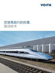
Multi-fl ow <strong>Pumps</strong><br />
Pump Combinations<br />
IPC 7<br />
<strong>IPV</strong> 7<br />
Combinations of <strong>IPV</strong> pumps<br />
<strong>IPV</strong> pumps of identical or different<br />
sizes can be combined in multiflow<br />
pumps.<br />
All sizes of the relevant pump<br />
volume are available as two- or<br />
three-flow pumps; four-flow<br />
pumps must be designed by<br />
<strong>Voith</strong> <strong>Turbo</strong> H + L Hydraulic.<br />
The pumps are arranged in<br />
increasing order according to<br />
frame size and delivery.<br />
<strong>Voith</strong> <strong>Turbo</strong> | <strong>IPV</strong> <strong>Catalog</strong> | G 1485 en<br />
IPH 6<br />
IPC 6<br />
<strong>IPV</strong> 6<br />
IPH 5 IPN 6<br />
IPC 5<br />
<strong>IPV</strong> 5<br />
Combinations of <strong>IPV</strong>/IP…pumps<br />
It is possible to combine <strong>IPV</strong><br />
pumps with other <strong>Voith</strong> <strong>Turbo</strong><br />
H + L Hydraulic pump series<br />
(e.g. medium-pres sure pumps<br />
IPC or low-<strong>pressure</strong> pumps IPN).<br />
The pumps are arranged by types<br />
and sizes as shown in the illustration<br />
above.<br />
If identical types or identical sizes<br />
follow each other, the pump with<br />
the higher pump flow is placed<br />
closer to the drive.<br />
Mounting, assembly<br />
IPH 4 IPN 5<br />
Multi-flow pumps are generally<br />
mounted to the drive by means of<br />
a flange. All information about the<br />
flange designs and shaft ends is<br />
found in the catalog of the relevant<br />
pump series.<br />
For more information, for example<br />
about definition of the adapter<br />
housings, refer to brochure<br />
G 1714 (<strong>Voith</strong> multi-flow pump).<br />
IPC 4<br />
<strong>IPV</strong> 4<br />
Pump combinations in order of type and size<br />
Selection<br />
IPN 4<br />
IPM 4<br />
<strong>IPV</strong> 3<br />
1. Determine <strong>pressure</strong> ranges and<br />
define the appropriate pump<br />
serie(s).<br />
2. Determine pump volume and<br />
select the appropriate size(s).<br />
3. Define sequence of the pumps.<br />
4. Check the torques.<br />
5. Determine rotation and suction.<br />
6. Specify mounting flange and<br />
shaft end.
Designs<br />
Rotation and suction Mounting fl ange Shaft end<br />
clockwise anti-clockwise<br />
2 7<br />
1 6 0<br />
2 7<br />
1 6<br />
3 8 0<br />
3 8<br />
Special design 4 9 Special design<br />
<strong>Voith</strong> <strong>Turbo</strong> | <strong>IPV</strong> <strong>Catalog</strong> | G 1485 en<br />
4<br />
7<br />
For designs and dimensions, see catalog<br />
of the relevant pump series.<br />
1<br />
4<br />
5<br />
7<br />
1<br />
5<br />
SAE 2-hole-flange<br />
SAE 4-hole-flange<br />
VDMA 2-hole-flange<br />
VDMA 4-hole-flange<br />
SAE 2-hole-flange<br />
1<br />
5<br />
1 0<br />
For designs and dimensions,<br />
see catalog of the<br />
relevant pump series.<br />
19
<strong>Voith</strong> <strong>Turbo</strong> H + L Hydraulic GmbH & Co. KG<br />
Schuckertstr. 15<br />
71277 Rutesheim, Germany<br />
Tel. +49 7152 992-3<br />
Fax +49 7152 992-400<br />
sales-rut@voith.com<br />
www.voithturbo.com/hydraulic-systems<br />
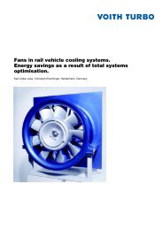
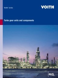
Plastics injection molding machine Folding press Punching press<br />
Hydraulic unit Lifting platform Marine applications<br />
Additional applications:<br />
Die casting machines<br />
Packing presses<br />
Shears<br />
Ground drilling machines<br />
Test rigs<br />
Hydraulic presses<br />
Crane building<br />
Lifting devices<br />
Garbage collection vehicles<br />
G 1485 en, 05.2009, aik, 0. Printed in Germany.<br />
Dimensions and illustrations non-committal, subject to change.