Voith Schneider Propeller Designer Manual - Voith Turbo
Voith Schneider Propeller Designer Manual - Voith Turbo
Voith Schneider Propeller Designer Manual - Voith Turbo

You also want an ePaper? Increase the reach of your titles
YUMPU automatically turns print PDFs into web optimized ePapers that Google loves.
<strong>Voith</strong> <strong>Schneider</strong> <strong>Propeller</strong><br />
<strong>Designer</strong> <strong>Manual</strong><br />
For safer shipping worldwide –<br />
Propulsion systems and ship<br />
concepts from <strong>Voith</strong> <strong>Turbo</strong><br />
Marine.<br />
Safety and precise maneuvering on<br />
the seas, lakes, rivers, waterways<br />
and harbors of the world is of maximum<br />
importance. Safe and ecofriendly<br />
drive systems are an essential<br />
prerequisite for this. For over 80<br />
years, <strong>Voith</strong> has been designing<br />
systems that are safe for people and<br />
the environment: a unique propulsion<br />
system – the <strong>Voith</strong> <strong>Schneider</strong><br />
<strong>Propeller</strong>, the <strong>Voith</strong> Radial <strong>Propeller</strong>,<br />
the <strong>Voith</strong> <strong>Turbo</strong> Fin and also worldwide<br />
proven ship concepts such as<br />
the <strong>Voith</strong> Water Tractor are proof<br />
of our comprehensive expertise in<br />
this branch of industry. And our<br />
customers benefit from the lowmaintenance<br />
and operationally safe<br />
systems, which guarantee a high<br />
level of availability and outstan ding<br />
quality.
<strong>Voith</strong> <strong>Schneider</strong> <strong>Propeller</strong><br />
Built in <strong>Voith</strong> <strong>Schneider</strong> <strong>Propeller</strong><br />
<strong>Voith</strong> <strong>Turbo</strong> <strong>Schneider</strong> Propulsion provides customized<br />
propulsion systems for the full range of applications<br />
from harbor and escort duties, through to ferries, military<br />
appli cations and special ships.<br />
<strong>Voith</strong> Water Tractor “Baut”, Norway Double-ended ferry “Rheintal”, Germany<br />
The <strong>Voith</strong> <strong>Schneider</strong> <strong>Propeller</strong><br />
(VSP) delivers thrust in all directions.<br />
It is a fast, continuously<br />
variable and precise vessel propulsion<br />
system combining propulsion<br />
and steering in a single unit. VSPequipped<br />
vessels do not require<br />
rudders. Thrust and steering forces<br />
between zero and maximum can<br />
be gener ated in any direction.<br />
On <strong>Voith</strong> <strong>Schneider</strong> <strong>Propeller</strong>s<br />
the propeller blades protrude at<br />
right angles from the rotor casing<br />
and rotate around a vertical axis.<br />
Each propeller blade performs an<br />
oscillatory motion around its own<br />
axis which is superimposed on the<br />
uniform rotary motion. The VSP is<br />
fitted in the vessel so that only the<br />
blades protrude from the hull.<br />
The blades themselves are manufactured<br />
from high-strength mate -<br />
rials and are extremely robust.
<strong>Propeller</strong> Well<br />
The propeller well, which acts as the foundation of the <strong>Voith</strong><br />
<strong>Schneider</strong> <strong>Propeller</strong>, consists of a cylindrical shell with a<br />
flange at the top. The propeller well must form an integral<br />
part of the bottom structure of the vessel so that, in addition<br />
to the propeller‘s weight, the forces and torque resulting from<br />
the propeller thrust can be transmitted into the ship‘s hull.<br />
This propeller thrust can vary by a full 360°.<br />
Attachment of the propeller <strong>Propeller</strong> foundation Final machining of the flange<br />
The sealing surface of the flange<br />
should be machined on board but<br />
this should be done only after in stal -<br />
lation of the complete well. The work<br />
should be performed with a suitable<br />
turning or milling machine according<br />
to the instructions provi ded by <strong>Voith</strong>.<br />
If such a machine is not available, a<br />
previously machined well can be<br />
welded in as a unit. After the welding<br />
the flange has to be checked on flatness<br />
and dimensional tolerances.<br />
A flat, approximately 2 mm-thick<br />
gasket, which is resistant to sea<br />
water and oil is located between<br />
the propeller well and the propeller.<br />
This gasket is part of the <strong>Voith</strong><br />
scope of supply.<br />
Through-bolts of quality class 8.8<br />
according to DIN 931 are used to<br />
fasten the propeller in place.<br />
Further details, especially in respect<br />
of propeller installation, the permissible<br />
tolerances, the number<br />
of con necting bolts and tightening<br />
torques, are described in the in -<br />
stallation instructions that are provided<br />
by <strong>Voith</strong>.<br />
2<br />
3
<strong>Propeller</strong> Installation<br />
To simplify transport, <strong>Voith</strong> <strong>Schneider</strong> <strong>Propeller</strong>s above size 26<br />
are supplied to the shipyard with the propeller blades removed.<br />
Blade installation is supervised by a <strong>Voith</strong> technician and can<br />
be carried out either prior to or following propeller installation<br />
to the vessel.<br />
Blade installation <strong>Propeller</strong> well Preparations prior to installation<br />
During propeller installation,<br />
the <strong>Voith</strong> <strong>Schneider</strong> <strong>Propeller</strong><br />
is first lowered onto the ready<br />
machined foundation.<br />
Alignment of the entire propulsion<br />
system is carried out<br />
in the following sequence:<br />
1. <strong>Voith</strong> <strong>Schneider</strong> <strong>Propeller</strong><br />
2. Propulsion engine<br />
3. Shaft line<br />
(final alignment with the<br />
vessel afloat)
<strong>Voith</strong> <strong>Schneider</strong> <strong>Propeller</strong> installation Built in <strong>Voith</strong> <strong>Schneider</strong> <strong>Propeller</strong><br />
<strong>Propeller</strong>s located below the design<br />
waterline are equipped with<br />
an ele vated oil tank. This allows<br />
the static oil pressure in the rotor<br />
casing to be increased to prevent<br />
water ingress into the propeller even<br />
when it is at a standstill. The elevated<br />
oil tank is part of the <strong>Voith</strong> scope<br />
of supply and should be mounted<br />
midships in the propeller area at a<br />
transverse bulkhead approx. 0.5<br />
to 2 m above the design waterline.<br />
The propeller must be filled with<br />
oil before the vessel is launched.<br />
<strong>Voith</strong> <strong>Schneider</strong> <strong>Propeller</strong>s are<br />
self-contained propulsion<br />
systems and do not require any<br />
secondary energy for operation.<br />
The VSP is ready for operation<br />
immediately after start-up of the<br />
main propul sion engine.<br />
4<br />
5
Propulsion Systems<br />
Interaction of Motor and <strong>Propeller</strong><br />
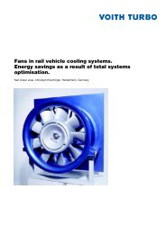
Diesel engine propulsion<br />
In the power range of the VSP,<br />
ship diesel engines are the most<br />
widely used propulsion units.<br />
The permissible propeller input<br />
speed can be selected freely<br />
within certain limits.<br />
In contrast to fixed pitch propellers,<br />
the variable pitch of the VSP allows<br />
full utilization diesel engine output<br />
across all vessel operation conditions.<br />
The direction of the <strong>Voith</strong> <strong>Schneider</strong> <strong>Propeller</strong>‘s motor does<br />
not need to be reversed and the propeller can be operated at<br />
a constant speed. Thanks to its variable pitch characteristic,<br />
the propeller thrust is variable in direction and magnitude.<br />
The propulsion motor is speed-controlled for economically<br />
efficient partial-load operation.<br />
Pitch variability makes it possible<br />
to make full use of the diesel<br />
engine speed output range, even<br />
when the propeller is subjected to<br />
very different loads.<br />
Engine curve<br />
<strong>Propeller</strong> curve<br />
for free running<br />
(100% pitch)<br />
In contrast to propellers with a fixed<br />
pitch, overloading of the main motor,<br />
so-called stalling, is prevented.<br />
Engine power [% ]<br />
100<br />
90<br />
80<br />
70<br />
60<br />
50<br />
40<br />
30<br />
20<br />
10<br />
0<br />
0 10 20 30 40 50 60 70 80 90 100<br />
Speed [% ]<br />
Diesel engine and <strong>Voith</strong> <strong>Schneider</strong> <strong>Propeller</strong> VSP power intake regulated by motor speed, at constant pitch<br />
From the viewpoint of economic<br />
efficiency, the power intake of the<br />
VSP should, whenever possible,<br />
only be varied under the following<br />
operating conditions:<br />
n Under different propeller loads,<br />
e.g. change from free vessel<br />
movement to standstill con di tions,<br />
braking operation, dynam ic ship<br />
assistance by the <strong>Voith</strong> Water<br />
Tractor<br />
n Vessel maneuvering<br />
n Below the minimum permissible<br />
speed of the main engine.
at standstill<br />
during free<br />
running<br />
Engine power [% ]<br />
100<br />
90<br />
80<br />
70<br />
60<br />
50<br />
40<br />
30<br />
20<br />
10<br />
0<br />
0 10 20 30 40 50 60 70 80 90 100<br />
Pitch [% ]<br />
VSP power input over pitch at constant speed<br />
Under defined partial load conditions,<br />
VSP power input at maxi mum<br />
pitch is controlled via the engine<br />
speed (e.g. varying speed settings<br />
for free-frunning vessels). The<br />
maxi mum power output of the main<br />
engine is measured during free<br />
running with a pitch setting of 100%<br />
and at a pitch setting of approx.<br />
80% at bollard pull conditions.<br />
Electric propulsion<br />
VWT “Svezia”, Italy<br />
Electric VSP propulsion is used<br />
when large amounts of electrical<br />
energy are required for other<br />
onboard equipment such as on<br />
floating cranes or ferries.<br />
As VSP power input is controlled by<br />
the variable propeller pitch, robust<br />
and reliable three-phase asynchronous<br />
motors can be used for propulsion.<br />
Depending on the application<br />
requirements, speed-controlled<br />
motors can also be used.<br />
To start the electro motors, a softstart<br />
device, such as a star-delta<br />
starting must be provided. The<br />
re spec tive breakaway torques are<br />
calculated by <strong>Voith</strong> <strong>Turbo</strong> <strong>Schneider</strong><br />
Propulsion on the basis of the<br />
para meters of the entire propulsion<br />
system.<br />
6<br />
7
Shaft Line<br />
Type DTL turbo coupling<br />
The shaft line for transmitting the<br />
motor output to the <strong>Voith</strong> <strong>Schneider</strong><br />
<strong>Propeller</strong> normally consists of a<br />
<strong>Voith</strong> turbo coupling and a displaceable<br />
curved teeth coupling<br />
with an intermediate shaft. The<br />
use of a hydrodynamic coupling<br />
guarantees smooth starting and<br />
stopping of the whole propulsion<br />
system.<br />
Moreover, the turbo coupling<br />
divides the entire vibration system<br />
into a primary and secondary side,<br />
Type DTL turbo coupling with constant oil filling<br />
whereby all the oscillatory pulses<br />
from the main motor are extensively<br />
dampened in the coupling<br />
and almost none are transmitted<br />
to the secondary side.<br />
There are basically two versions<br />
of the turbo coupling:<br />
1. <strong>Turbo</strong> coupling with constant<br />
oil filling<br />
2. <strong>Turbo</strong> coupling with oil flow<br />
control
Type TM1 VTK turbo coupling with constant oil filling Double-ended ferry “Sahilbent”, Turkey<br />
For most applications turbo couplings<br />
with constant oil filling can be<br />
used. These are virtually wear-free<br />
and therefore require little maintenance.<br />
In the majority of cases we<br />
supply turbo couplings with constant<br />
oil filling for direct installation onto<br />
the engine. The engine manufacturer<br />
must determine whether the<br />
engine can withstand the load<br />
reaction on the turbo coupling input<br />
side. If this is not the case, turbo<br />
couplings with pedestal bearings<br />
at the input and output side can<br />
be supplied.<br />
In this case, the engine manu -<br />
fac turer must design and supply<br />
the required resilient coupling<br />
between engine and turbo coupling.<br />
Flow-controlled turbo couplings<br />
are only used for special applications<br />
such as when extremely high<br />
torques or speeds are required.<br />
Smaller Type R4 propellers or propulsion<br />
units with an electric drive<br />
do not require turbo couplings.<br />
For Type R4 propellers with diesel<br />
engine propulsion, clutch couplings<br />
must be used instead of turbo<br />
couplings.<br />
The propeller input shaft must be<br />
linked to the downstream shaft<br />
line/turbo coupling output shaft by<br />
means of a displaceable coupling<br />
or drive shaft.<br />
8<br />
9
Fire-fighting boat for Los Angeles, USA Buoy laying vessel “Chef de Caux”, France<br />
Provision of fire-fighting<br />
capacity<br />
Today, increasing the fire fighting<br />
capacity of ships is becoming<br />
increasingly important in modern<br />
harbors. For the provision of higher<br />
fire-fighting capacities, powerful<br />
motors are needed which are operated<br />
only rarely. As a result, the<br />
cost of maintenance increases.<br />
When the VSP with a variable pitch<br />
characteristics is used, it is possible<br />
to connect firefighting pumps to the<br />
main engine via a power take-off<br />
(PTO). Additional motors for firefighting<br />
pumps are not necessary.<br />
During firefighting, the pitch and<br />
therefore the power intake of the<br />
VSPs are reduced to 30 %.<br />
The remaining power can then be<br />
used for the fire-fighting pumps,<br />
without the main engine being overloaded.<br />
The ship continues to be<br />
fully maneuverable and can therefore<br />
assume and retain the optimum<br />
position for fighting the fire.
1 VSP type R5/…-2 (two-step)<br />
2 VSP type R5/…-1 (one-step)<br />
3 Displaceable coupling with intermediate shaft<br />
4 Cardan shaft<br />
5 VTK, type DTL/TL<br />
6 VTK, type DTm1/Tm1<br />
7 Diesel engine<br />
8 Electric motor<br />
9 Elastic coupling<br />
10 VTK, type T<br />
11 Step-down gear<br />
12 Step-down gear with clutch<br />
13 Displaceable coupling<br />
These illustrations show some proven examples of shaft<br />
lines as an orientation aid for project planning.<br />
10<br />
11
<strong>Voith</strong> <strong>Turbo</strong> <strong>Schneider</strong> Propulsion<br />
GmbH & Co. KG<br />
Alexanderstraße 18<br />
89522 Heidenheim, Germany<br />
Tel. +49 7321 37-6595<br />
Fax +49 7321 37-7105<br />
vspmarine@voith.com<br />
www.voithturbo.com/marine<br />
G 1861 e 2009-12 3000 ak/WA Printed in Germany. Dimensions and illustrations non-committal, subject to change.