A Procedure for Designing EMI Filters for AC Line Applications ...
A Procedure for Designing EMI Filters for AC Line Applications ...
A Procedure for Designing EMI Filters for AC Line Applications ...

You also want an ePaper? Increase the reach of your titles
YUMPU automatically turns print PDFs into web optimized ePapers that Google loves.
170<br />
IEEE TRANS<strong>AC</strong>TIONS ON POWER ELECTRONICS, VOL. 11, NO. 1, JANUARY 1996<br />
rocedure <strong>for</strong> <strong>Designing</strong> EM1 <strong>Filters</strong><br />
<strong>for</strong> <strong>AC</strong> <strong>Line</strong> <strong>Applications</strong><br />
Fu-Yuan Shih, Dan Y. Chen, Senior Member, IEEE, Yan-Pei Wu, and Yie-Tone Chen, Member, IEEE<br />
Abstract-A procedure <strong>for</strong> designing ac line <strong>EMI</strong> filters is<br />
presented. This procedure is based on the analysis of conducted<br />
EM1 problems and the use of a noise separator. Design examples<br />
are given, and results are experimentally verified.<br />
I. INTRODUCTION<br />
IXING conducted electromagnetic interference (<strong>EMI</strong>)<br />
problems is not an exact science. It normally involves a<br />
cut-and-trial process <strong>for</strong> a designer to come up with a proper<br />
filter design. As such, designing a filter is a time-consuming<br />
process <strong>for</strong> beginning engineers as well as <strong>for</strong> experienced<br />
engineers when they face new design circumstances.<br />
In this paper, a procedure <strong>for</strong> designing EM1 filters <strong>for</strong> ac<br />
line-powered equipment will be presented. This procedure is<br />
based on the analysis of conducted EM1 problems and the use<br />
of an EM1 diagnostic tool, noise separator, developed recently<br />
[I]. The noise separator, constructed from a radio-frequency<br />
power splitter, can be used to separate differential-mode (DM)<br />
and common-mode (CM) noise. This greatly simplifies the<br />
filter design process. In the paper, a review of conducted<br />
EM1 problems will be given first. Factors affecting EM1<br />
per<strong>for</strong>mance and issues of filter design will be described. From<br />
the discussion, a practical approach to designing EM1 filters<br />
emerges and a design procedure will be proposed. Numerical<br />
examples will be given to illustrate the design procedure and<br />
the results are experimentally verified.<br />
G&-<br />
N-<br />
LISN<br />
Spectrum ' I Analvzer<br />
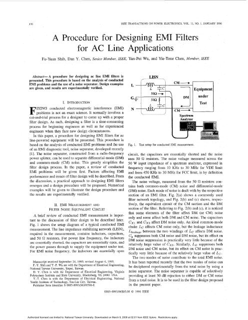
Fig. 1. Test setup <strong>for</strong> conducted EM1 measurement.<br />
circuit, the capacitors are essentially shorted and the noise<br />
sees 50 R resistors. The noise voltage measured across the<br />
50 W input impedance of a spectrum analyzer, expressed in<br />
frequency ranging from 10 KHz to 30 MHz <strong>for</strong> VDE limit<br />
md from 450 KHz to 30 MHz <strong>for</strong> FCC limit, is by definition<br />
the conducted <strong>EMI</strong>.<br />
The noise voltage, measured from the 50 R resistors contains<br />
both common-mode (CM) noise and differential-mode<br />
(DM) noise. Each mode of noise is dealt with by the respective<br />
section of an EM1 filter. Fig. 2(a) shows a commonly used<br />
filter network topology, and Fig. 2(b) and (c) shows, respec-<br />
11. EM1 MEASUREMENT AND<br />
tively, the equivalent circuit of the CM section and the DM<br />
FILTER NOISE EQUIVALENT CIRCLJIT<br />
section of the filter. Referring to Fig. 2(b) and (c), it is noticed<br />
that some elements of the filter affect DM (or CM) noise<br />
A brief review of conducted EM1 measurement is imporonly<br />
and some affect both DM and CM noise. The capacitors<br />
tant to the discussion of filter design to be described later.<br />
6x1 and CXZ affect DM noise only. An ideal common-mode<br />
Fig. 1 shows the setup diagram of a typical conducted EM<br />
choke LC affects CM noise only, but the leakage inductance<br />
measurement. The line impedance stabilizing network (LISN),<br />
Lleafcage between the two windings of LC affects DM noise.<br />
required in the measurement, contains inductors, capacitors,<br />
C, suppresses both CM noise and DM noise, but its effect on<br />
and 50 R resistors. For power line frequency, the inductors<br />
DM noise suppression is practically very little because of the<br />
are essentially shorted, the capacitors are essentially open, and<br />
relatively large value of 6x2. Similarly, LD suppresses both<br />
the power passes through to supply the equipment under test.<br />
DM noise and CM noise, but its effect on CM noise is prac-<br />
For EM1 noise frequency, the inductors are essentially open<br />
tically very little because of the relatively large value of Lc.<br />
The two modes of noise contribute to the total EM1 noise.<br />
Manuscnpt received September 24, 1995, revised August 4, 1995. It has been reported recently that the two modes of noise can<br />
F.-Y Shih and y -p WU are With the Department Of Electrical Engineering,<br />
be deciphered experimentally from the total noise by using a<br />
Nabonal Taiwan Umversity, Trupei, Taiwan.<br />
D Y Chen IS with the Department of Electrical Engineenng, Virginia noise Separator. The noise separator is capable of selectively<br />
Polytechnic Inshtute and State University, Blacksburg, VA 24061 USA providing at least 50 dB rejection to either DM or CM noise<br />
-T Chen with the Department Of National<br />
from a total noise. It is to be used in the filter design proposed<br />
Yunlin Inshtute of Technology, Tou-Lm Clty, Truwan.<br />
Publisher Item Identifier S 0885-8993(96)00586-8<br />
in the present paper.<br />
0885-8993/96$05.00 0 1996 LEEE<br />
Authorized licensed use limited to: National Taiwan University. Downloaded on March 9, 2009 at 02:01 from IEEE Xplore. Restrictions apply.
SHIH et al.: DESIGNING EM1 FILTERS FOR <strong>AC</strong> LINE APPLICATIONS 171<br />
L<br />
G<br />
N<br />
L<br />
N<br />
.<br />
(C)<br />
Fig. 2. (a) Typical EM1 filter topology. (b) CM noise equivalent circuit of<br />
(a). (c) DM noise equivalent circuit of (a).<br />
111. DIFFICULTIES OF PREDICTING<br />
CONDUCTED EM1 PERFORMANCE<br />
There are several reasons, both theoretical and practical,<br />
why it is difficult to predict conducted EM1 per<strong>for</strong>mances.<br />
They are described in the following. From the difficulties<br />
described, a practical procedure <strong>for</strong> designing the EM1 filter<br />
emerges and will be described in Section IV.<br />
1) DM and CM noises are coupled through different paths to<br />
the measured <strong>EMI</strong>. Equipment package and component layout<br />
all affect the coupling paths. but the effects are very difficult<br />
to quantify. Often, a seemingly small change in layout could<br />
lead to significant change in EM1 per<strong>for</strong>mance.<br />
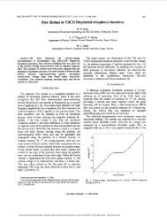
2) The effectiveness of an EM1 filter depends not only<br />
on the filter itself but also on the noise source impedance<br />
[2]. Fig. 3(a) shows a typical power converter and the related<br />
input wave<strong>for</strong>ms. The equivalent models of CM and DM noise<br />
source impedances of Fig. 3(a) are depicted in Fig. 3(b) and<br />
(c), respectively. For CM noise, the source is modeled by a<br />
current source in parallel with a high source impedance Zp.<br />
For DM noise, the source is modeled by a voltage source in<br />
series with a low impedance or a current source in parallel with<br />
a high impedance dependent on the state of the input rectifier<br />
diodes [2]. When two of the rectifier diodes are conducting, the<br />
noise source is modeled by a voltage source in series with low-<br />
impedance source ZS, and when all of the four diodes are cut<br />
off, the noise is modeled by a current source in parallel with<br />
a high-impedance Zp. The DM equivalent circuit there<strong>for</strong>e<br />
fluctuates between these !WO model at two times the line fre-<br />
quency. 2s is associated with wire inductance and resistance,<br />
0294 on Diodes off ~193 on<br />
- Power Converter<br />
.................................................................<br />
.............................................................. .d<br />
(b)<br />
.....................................................................................................................<br />
2 x \ line freq.<br />
Load<br />
... .................................................................................................................. .<br />
(C)<br />
Fig. 3. (a) Typical power converter and the related input wave<strong>for</strong>ms. (b)<br />
Equivalent model of CM noise source of (a). (c) Equivalent model of DM<br />
noise source of (a).<br />
and Zp is associated with diode parasitic capacitance. These<br />
source impedances depend on parasitic parameters and are<br />
there<strong>for</strong>e package-dependent. Although the source impedances<br />
can be measured, this is practically difficult [2].<br />
Authorized licensed use limited to: National Taiwan University. Downloaded on March 9, 2009 at 02:01 from IEEE Xplore. Restrictions apply.
112 IEEE TRANS<strong>AC</strong>TIONS ON POWER ELECTRONICS, VOL. 11, NO. 1, JANUARY 1996<br />
Block I<br />
Block11 I<br />
I Yes<br />
Lower the Filter Block In<br />
. - . . . - - -<br />
Comer Frequenc<br />
. . .. .<br />
I END ld 1<br />
Fig. 4. Design flow chart of EM1 filters.<br />
3) Beyond a certain frequency, the effects of parasitic<br />
elements start to surface. This frequency is the dividing<br />
line between “high frequency” and “low frequency” used in<br />
the paper here. High-frequency effects include permeability<br />
reduction of choke core, parasitic capacitance effect of the<br />
inductor, and the parasitic inductance effect of filter capacitors.<br />
Besides the effects of parasitic elements, radiation coupling<br />
and source impedance-filter capacitor resonance [4] could<br />
also affect high-frequency EM1 per<strong>for</strong>mance. These effects,<br />
however, are difficult to predict without experiments.<br />
IV. PR<strong>AC</strong>TICAL APPRO<strong>AC</strong>H TO DESIGNING EM1 FILTERS<br />
From the discussion of the last section, it is clear that it<br />
is extremely difficult to analytically arrive at an EM filter<br />
design. A practical approach is proposed here to deal with the<br />
difficult issue. This approach is based on the following three<br />
understandings :<br />
1) Base-line (i.e., without filter) EM1 noise must be provided<br />
to filter designer. This in<strong>for</strong>mation is obtained either through<br />
past history or actual measurement. For products without past<br />
history, it is difficult to estimate the base-line EM1 noise,<br />
and the in<strong>for</strong>mation must be obtained by measurement. The<br />
noise separator mentioned earlier will be used in obtaining the<br />
base-line level <strong>for</strong> both the CM and DM noise.<br />
2) Although, in general, noise source impedance affects filter<br />
attenuation, it can be proved that as long as the filter elements<br />
are properly arranged and sized, source impedance has little<br />
effect. There<strong>for</strong>e, analytical design of the filter is possible<br />
without knowing exactly the source impedance values. The<br />
detailed explanations are given in Section IV-B.<br />
3) Because it is difficult to predict high-frequency per<strong>for</strong>-<br />
mance at the stage of filter design, the focus of the filter design<br />
procedure is to meet the low-frequency specification. After the<br />
filter is designed and built, high-frequency per<strong>for</strong>mance can<br />
be tuned if necessary.<br />
#.:<br />
A. Design Flow Chart<br />
Based on the preceding discussion, a flow chart <strong>for</strong> EM1<br />
filter design is proposed in Fig. 4. In Block I of the chart,<br />
filter attenuation requirement is obtained first. This involves<br />
the use of a noise separator <strong>for</strong> base-line noise measurement<br />
<strong>for</strong> both CM and DM noise. Based on the in<strong>for</strong>mation obtained<br />
in Block I, component values of an EM1 filter will be determined<br />
in Block 11, mainly to meet low-frequency specification.<br />
Theoretically speaking, the filter design obtained in Block I1<br />
should meet both the low-frequency and the high-frequency<br />
specification. However, many high-frequency effects, which<br />
are difficult to deal with at the design stage of the filter,<br />
may cause the violation of high-frequency design specification.<br />
Block III provides a list of possible causes of such violation,<br />
which include high-frequency parasitic effects of filter components,<br />
radiation coupling problems, filter source-impedance<br />
resonance, and filter underdamped resonance. The main focus<br />
of the present paper is on Blocks I and 11. Block I11 is beyond<br />
the scope of the paper.<br />
B. Basis of Determining Filter Component Values<br />
1) Common Mode: From Figs. 2(b) and 3(b), the CM noise<br />
equivalent circuit can be represented by Fig. 5(a). If the<br />
impedance conditions indicated in the figure are met, then<br />
the filter attenuation by the transfer function VS,CM/VO,CM is<br />
shown in Fig. 5(c). In the figure, the filter attenuation is defined<br />
as VLISN(without filter)/VLlsN(with filter). Notice that the<br />
Reciprocity Theorem (open circuit voltage ratio is equal to<br />
short circuit reverse current ratio) is used from Fig. 5(b) to<br />
(c). The filter attenuation is there<strong>for</strong>e determined by LCM (=<br />
Lc + Lo/2) and (= 2Cy) and is independent of source<br />
impedances. Fig. 5(d) shows the plot of CM noise attenuation<br />
versus frequency. Normally, LC >> $LD and the corner<br />
frequency ~R,CM is mainly determined by LC and Cy values.<br />
This figure will be used in Section V <strong>for</strong> the determination<br />
of CM filter component values. It is noted that the impedance<br />
inequalities indicated in Fig. 5 are normally met in typical<br />
filters [3].<br />
2) DifSerentiuZ Mode: It was shown in Fig. 3(c) that the<br />
source impedance of the DM noise <strong>for</strong> an ac line-powered<br />
circuit can be either “high” or “low,” depending on the<br />
conducting state of the rectifier diodes. Fig. 6 shows the<br />
two noise equivalent circuits and the graphical explanation<br />
leading to the derivation of filter attenuation of DM filter.<br />
When the rectifier diodes are off, a high-Z model <strong>for</strong> the<br />
noise source is used and the equivalent circuit is shown in<br />
Fig. 6(a). When diodes are on, the low-Z model shown in<br />
Fig. 6(b) is used. If the impedance conditions indicated in the<br />
figure are met, then the filter attenuation can be approximated<br />
by the transfer function V,,DM/V~,DM of Fig. 6(e) and (f).<br />
Notice that from Fig. 6(c) to (e), the Reciprocity Theorem<br />
is used. DM equivalent circuit fluctuates between the two<br />
models every 2xline frequency; it is difficult to distinguish<br />
the individual contribution to the total DM noise. However, if<br />
(2x1 = CX~ = CDM, the total filter attenuation to DM noise<br />
is determined by LDM (= 2. LD + Llealcage) and CDM alone.<br />
The attenuation is there<strong>for</strong>e approximated by a 40dB/dec-<br />
Authorized licensed use limited to: National Taiwan University. Downloaded on March 9, 2009 at 02:01 from IEEE Xplore. Restrictions apply.
SHIH et ab: DESIGNING EM1 FILTERS FOR <strong>AC</strong> LINE APPLICATIONS 173<br />
LISN <strong>EMI</strong> Filter<br />
CM Noise.<br />
................ ............................................................. ...... ..................................<br />
L . .. ..' ,<br />
. .<br />
: i<br />
i : i<br />
. i. . . , . .<br />
.........................................................................................................................<br />
.<br />
vs.w<br />
CM Attenuation<br />
4<br />
@) I<br />
.<br />
Reciprocity Theorem<br />
Frequency<br />
Fig. 5. Equivalent circuits <strong>for</strong> the derivation of CM filter attenuation. (a) CM equivalent circuit. (b) Equivalent circuit of (a) if & > 25 0. (c) Equivalent circuit of (b) by using Reciprocity Theorem. (d) Filter attenuation <strong>for</strong> common-mode noise.<br />
slope line going through LDMCDM resonance frequency, as<br />
shown in Fig. 6(g). Notice that there is no peaking effect at<br />
the resonance in Figs. 5(d) and 6(g). In practical filters there<br />
is usually enough damping that at resonant frequency there<br />
is no peaking.This figure will be used in Section V <strong>for</strong> the<br />
determination of DM filter component values. It is also noted<br />
that the inequalities indicated in Fig. 6 are met <strong>for</strong> typical<br />
filters PI.<br />
Authorized licensed use limited to: National Taiwan University. Downloaded on March 9, 2009 at 02:01 from IEEE Xplore. Restrictions apply.
174 IEEE TRANS<strong>AC</strong>TIONS ON POWER ELECTRONICS, VOL 11, NO. 1, JANUARY 1996<br />
(cl I<br />
DM Attenuation<br />
Reciprociiy Theorem<br />
Fig. 6. Equivalent circuits <strong>for</strong> the derivation of DM filter attenuation. (a) DM equivalent circuit when rectifier diodes are conducting. (b) DM equivalent<br />
circuit when rectifier diodes are not conducting. (c) Equivalent circuit of (a) if l/wCxl >> 100 R, l/wCXz > 100 R. (d) Equivalent<br />
circuit of (b) if l/wCxz >> 2,. (e) Equivalent circuit of (c) by using Reciprocity Theorem. (0 Equivalent circuit of (d) if l/wCxl
SHIH et al.: DESIGNING EM1 FILTERS FOR <strong>AC</strong> LINE APPLICATIONS<br />
TO<br />
h<br />
\<br />
Filter<br />
e-<br />
iao<br />
100<br />
00<br />
EO<br />
40<br />
.om<br />
JE<br />
vcc vcc I #J<br />
-<br />
Control 8 Drive<br />
+5v<br />
CN0-L<br />
Circuit<br />
-- OPtLcal Optical<br />
I sol at or<br />
I d I I I<br />
$<br />
Feedback<br />
a$* A Feedback I-’<br />
rncnUENcY KWZl<br />
(4<br />
T - * *U<br />
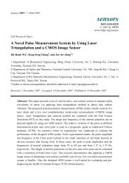
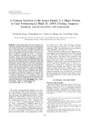
Fig. 7. (a) Circuit diagram of a 43 W flyback switching power supply. (b) Base-line CM noise of (a). (c) Base-line DM noise of (a). (d) Base-line<br />
total noise of (a).<br />
Authorized licensed use limited to: National Taiwan University. Downloaded on March 9, 2009 at 02:01 from IEEE Xplore. Restrictions apply.<br />
t<br />
f-<br />
175
176 IEEE TRANS<strong>AC</strong>TIONS ON POWER ELECTRONICS, VOL. 11, NO. 1, JANUARY 1996<br />
80.00<br />
1<br />
1 fR,a 4?:&f*/<br />
000 I I , , , , , / I , I ,1111 , , , ,<br />
0.01 0.10 1 .w 1o.m<br />
Frequency [MHz]<br />
Fig. 8. (a) CM attenuation requirement <strong>for</strong> Example 1: ~ CM<br />
tion req. ( V&,C~~)~B;<br />
requirement <strong>for</strong> Example 1: ~ DM<br />
- .. - 40 dB/dec-slope line.<br />
(a)<br />
attentua-<br />
- .. - .. - 40 dB/dec-slope line. (b) DM attenuation<br />
attentuation req. (Vreq,~~)d~; - ..<br />
may be needed to meet the high-frequency specification, but<br />
this modification is beyond the scope of the paper.<br />
A. Design <strong>Procedure</strong><br />
Step 1: Measure base-line (i.e., without filter) common-<br />
mode EM1 noise VCM and differential-mode EM1 noise VDM<br />
using a noise separator.<br />
Step 2: Determine CM attenuation requirement V&CM<br />
and DM attenuation requirement V&DM<br />
(Vreq,cn/r)dB (VCM)~B - (VLimit)dB + 3dB<br />
(V,~~,DM)~B = (VDM)~B - (VLimit)dB + 3dB<br />
\-,<br />
Fig. 9. (a) Measured CM noise <strong>for</strong> Example 1 when Filter A is used (b)<br />
where (VCn/r)dB and (bl%f)dB are Obtained from step and<br />
(VL~~~~)~B<br />
is the conducted EM1 limit specified by FCC or<br />
Measured DM noise <strong>for</strong> Example 1 when Filter A is used. (c) Measured total<br />
noise <strong>for</strong> Example 1 when FilterA is used,<br />
VDE. A “+3dB” is needed because DM or CM measurement ilarly, DM corner frequency fR,oM can also be determined<br />
using the Noise Separator is 3dB above the actual value [I].<br />
Step 3: Determine filter corner frequencies.<br />
from (Keq,~~)d~.<br />
Step 4: Determine filter component values.<br />
Based on Fig. 5(d), filter comer frequency ~R,CM can be a) CM component LC and Cy: Since there is a safety leakobtained<br />
by drawing a 40dB/dec-slope line that is tangent to age current requirement, Cy is normally limited to 3300 pF<br />
the (Keq,c~)d~ obtained in Step 2. The horizontal intercept of <strong>for</strong> 60 Hz operation. LC and 2Cy should have a resonant<br />
the line determines the CM filter corner frequency j’E,CM Sim- frequency of ~R,CM obtained in Step 3.<br />
Authorized licensed use limited to: National Taiwan University. Downloaded on March 9, 2009 at 02:01 from IEEE Xplore. Restrictions apply.
SHIH et al.: DESIGNING EM1 HLTERS FOR <strong>AC</strong> LINE APPLICATIONS<br />
rnmwav WI<br />
Fig. 10. DM noise <strong>for</strong> Example 1 when Filter B is used.<br />
There<strong>for</strong>e<br />
1<br />
Lc=( ) .-<br />
2~ * ~R,CM 2 . Cy ‘<br />
b) DM component LD, CX~ and CX~: Based on the description<br />
given in Section IV-B, CX, and Cx2 are selected<br />
to be the same value CDM and are related to LDM through<br />
corner frequency ( ~R,DM) requirement as shown by (2)<br />
2<br />
Cx1=Cx2=Cm= ( 1 )2.L. (2)<br />
2K’fR,DM LDM<br />
In (2), fR,DM value has been found in Step 3. Cxl, CX~, and<br />
LDM are unknowns. There exists some degree of freedom <strong>for</strong><br />
trade-off. The larger the LDM value selected, the smaller the<br />
Cxl, CX, are needed, and vice versa. In choosing the CXS’<br />
value, input filter stability problem must also be considered<br />
PI.<br />
Since the leakage inductance of a CM choke can be utilized<br />
as a DM choke, separate DM chokes may not be needed in<br />
some cases. Practically, Lleakage is generally in the range of<br />
0.5-2% of the LC value.<br />
E. Design Examples<br />
1<br />
Bo.00,<br />
8..<br />
.i. fQ,a = 4o.oKH.z<br />
i‘<br />
,, ‘ fQm = 1 L .1mz<br />
Nois8 Floor Law1<br />
Nois# floor Law1<br />
Fig. 11. Comparisons of the actual filter per<strong>for</strong>mance and the predicted<br />
per<strong>for</strong>mance of Example 1 when Filter A is used. (a) CM attenuation. (b)<br />
DM attenuation. --A--- experimental attentuation; - .. - .. - theoretical<br />
attentuation.<br />
Step3: From Fig. 8(a) and (b), ~R,CM = 40.3 KHz and<br />
~R,DM = 12.0 KHZ<br />
Step 4a): Use Cy =3300 pF, calculate Lc according to (1)<br />
r 12<br />
Lc = 12, x (40:s x lo3)] * + 2 3300 x<br />
1<br />
b<br />
b<br />
= 2.36mH.<br />
Two design examples are given below to illustrate the design<br />
steps described above. Filter topology shown in Fig. 2(a) is Select LC = 2.4 mH, and the leakage inductance Lleakage =<br />
used. One example is <strong>for</strong> the flyback converter power supply, 36 pH can be obtained by measurement.<br />
and the other is <strong>for</strong> the <strong>for</strong>ward converter power supply. The Step 4b): Using f ~ , = p 12.0 ~ KHz in (2), there are<br />
results of both examples are verified experimentally. infinite sets of solution <strong>for</strong> LDM and CDM. Three sets of<br />
Example I: Design an EM1 filter <strong>for</strong> an off-line (90-260 solution are listed <strong>for</strong> discussion in the following:<br />
V) flyback converter switching power supply (90 KHz, 43 W Use the leakage inductance as the DM choke. Since<br />
output), as shown in Fig. 7(a), to meet a VDE limit. For proper LDM = Lleakage = 36pH, then CO, (= Cxl =<br />
margin, under 6 dB limit is used in the design [see Fig. 7(b)]. CX~) = 4.75 pF, which is an impractical value <strong>for</strong> line-<br />
Step I: The base-line CM noise VCM and the base-line DM voltage rated filter capacitor. The physical volume of<br />
noise VDM of the tested circuit, measured by using a noise such a capacitor is much too bulky.<br />
separator, is shown in Fig. 7(b) and (c), respectively. Fig. 7(d) If CDM are chosen to be 0.47 pF, a commonly available<br />
shows the total noise V&al of the tested circuit.<br />
filter capacitor value, then LDM = 374pH and LD =<br />
Step 2: The CM attenuation requirement ( Keq,c~)d~ and LDM - Lleakage/2 = 169pH, a practical inductance<br />
the DM attenuation requirement ( K e q , ~ ~ are ) d plotted ~ in value. Select LD = 180pH.<br />
log-log scale, as shown in Fig. 8(a) and (b). The line labeled If CDM = 0.22pF, then LDM = 800pH and LD =<br />
“Under 6 dB” is used as the (Kzmzt)d~.<br />
382 pH, a practical value also. Select LD = 380 pH.<br />
Authorized licensed use limited to: National Taiwan University. Downloaded on March 9, 2009 at 02:01 from IEEE Xplore. Restrictions apply.
178<br />
U<br />
c<br />
80.00<br />
40.00<br />
0.00<br />
L<br />
G<br />
N<br />
&,a=ll9.lmz<br />
lEEE TRANS<strong>AC</strong>TIONS ON POWER ELECTRONICS, VOL. 11, NO. 1, JANUARY 1996<br />
F I<br />
I I 1 1 1 1 1 1 I I l l 1 1 1 1 I I I I I I J I , I 0.W<br />
0 01 0.10 1 .oo 10.00 0.01 0.10 1 .00 10.00<br />
Frequency [MHz] Frequency [MHz]<br />
(4 (e)<br />
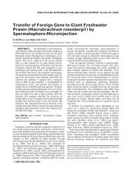
Fig. 12. (a) A smaller filter used to compare the actual filter per<strong>for</strong>mance and the predicted per<strong>for</strong>mance. (b) Measured CM noise <strong>for</strong> Example 1 when the<br />
filter shown in (a) is used (c) Measured DM noise <strong>for</strong> Example 1 when the filter shown in (a) is used (d) CM attenuahon comparison of the actual filter<br />
per<strong>for</strong>mance and the predicted per<strong>for</strong>mance of Example 1 when the filter shown in (a) is used. (e) DM attenuahon comparison of the actual filter per<strong>for</strong>mance<br />
and the predicted per<strong>for</strong>mance of Example 1 when the filter shown in (a) is used. ~ expenmental attentuation; - - theoretical attentuation.<br />
From the procedure, two filter designs were obtained Discussion: Both sets of filter design were constructed and<br />
tested. Fig. 9 shows the conducted <strong>EMI</strong> test <strong>for</strong> the power<br />
supply using Filter A. It can be seen from the figure, Filter<br />
Fzlter A: LC = 2.4mH (Lleakage = 36pH), LD = I8OpH, A meets the low-frequency design goal, which is the main<br />
(7x1 = Cx2 = 0.47pF, Cy = 3300pF.<br />
focus of the paper. Around 20 MHz, the emission exceeds<br />
F&er B: L~ = 2 .4m~ ( L = 36pH), ~ LD = ~ 380pj3, ~ the ~ limit. It ~ was observed ~ that ~ the emission around 20 MHz<br />
was caused by radiation coupling. By rearranging the wiring<br />
Cxl = (3x2 = 0.22 pF, Cy = 3300 pF.<br />
between the <strong>EMI</strong> filter and the power supply, the problem was<br />
Authorized licensed use limited to: National Taiwan University. Downloaded on March 9, 2009 at 02:01 from IEEE Xplore. Restrictions apply.
SHIH et al.: DESIGNING EM1 FILTERS FOR <strong>AC</strong> LINE APPLICATIONS<br />
To -12V/0.5&<br />
Fi 1<br />
vcc<br />
- +5V / IOR<br />
Control (L Drive<br />
Circuit<br />
-<br />
CND & = 0PtLC.l<br />
Is01 at or<br />
$<br />
-<br />
(a)<br />
FnIIPUWCY Wnrl<br />
(4<br />
F~edb8ck<br />
Fig. 13. (a) Circuit diagram of a 100 W <strong>for</strong>ward switching power supply. (b) Base-line CM noise of (a). (c) Base-line DM noise of (a). (d) Base-line<br />
total noise of (a).<br />
Authorized licensed use limited to: National Taiwan University. Downloaded on March 9, 2009 at 02:01 from IEEE Xplore. Restrictions apply.<br />
179
180<br />
"0° 1<br />
0.01 0.10 1 .oo 10.00<br />
1<br />
Frequency [MHzj<br />
Fig. 14. (a) CM attenuation requirement <strong>for</strong> Example 2 ~ CM attentuation<br />
req. (VTeQ,cn/l)d~; 40 dB/dec-slope line. (b) DM attenuation<br />
requirement <strong>for</strong> Example 2: ~<br />
-. . - 40 dB/dec-slope line.<br />
DM attentuation req. (Vreq,~~)d~;<br />
eliminated. Test results <strong>for</strong> Filter B show similar results and<br />
will not be repeated except <strong>for</strong> DM emission. Fig. 10 shows<br />
the DM emission (<strong>for</strong> Filter B), which is essentially the same<br />
as the DM emission <strong>for</strong> Filter A. It confirms that the two DM<br />
filter designs in Step 4(b) meet the same goal.<br />
A comparison of the actual filter per<strong>for</strong>mance and the<br />
predicted per<strong>for</strong>mance is given in Fig. 11. At low frequency<br />
both agree well. However, the comparison was not made<br />
beyond 540 KHz frequency because the noise level has already<br />
been reduced to noise floor level beyond this frequency, and<br />
the comparison is meaningless. In order to verify the results<br />
though, a much smaller filter [see Fig. 12(a)] was deliberately<br />
used so that a meaningful comparison could be made. The<br />
per<strong>for</strong>mance is shown in Fig' 12(b) <strong>for</strong> 'IVt and 12(')<br />
<strong>for</strong> DM. The resultant comparison is shown in Fig. 12(d) and<br />
(e). From the comparison, the theoretical and the experimental<br />
results agree well below 700 KHz <strong>for</strong> both the CM and DM<br />
emission. Beyond 700 KHz, the two begin to deviate. It was<br />
found out that the deviation around 700 KHz was caused by the<br />
fact that the impedance of the 1.9 mH CM choke used in the<br />
test starts to peak and becomes capacitive around 900 KHz due<br />
to core permeability reduction and parasitic capacitance. This<br />
IEEE TRANS<strong>AC</strong>TIONS ON POWER ELECTRONICS, VOL. 11, NO. 1, JANUARY 1996<br />
Fig. 15. (a) Measured CM noise <strong>for</strong> Example 2 when the calculated EM1<br />
filter is used. (b) Measured DM noise <strong>for</strong> Example 2 when the calculated EM1<br />
filter is used. (c) Measured total noise <strong>for</strong> Example 2 when the calculated<br />
<strong>EMI</strong> filter is used.<br />
onf firms earlier assertion that high-frequency per<strong>for</strong>mance is<br />
difficult to predict and can only be modified after the filter has<br />
been constructed and tested.<br />
Example 2: Design an EM1 filter <strong>for</strong> an off-line (90-260 V)<br />
<strong>for</strong>ward switching power supply (130 KHz, 100 W output), as<br />
shown in Fig. 13(a), to meet a VDE limit.<br />
Authorized licensed use limited to: National Taiwan University. Downloaded on March 9, 2009 at 02:01 from IEEE Xplore. Restrictions apply.
SHIH er al.: DESIGNING EM1 FILTERS FOR <strong>AC</strong> LINE APPLICATIONS 181<br />
Step I: Fig. 13(b) and (c) shows the base-line CM noise<br />
REFERENCES<br />
VCM and the base-line DM noise VDM of the tested circuit,<br />
respectively. Fig. 13(d) shows the total noise V T of ~ the ~<br />
tested circuit.<br />
Step 2: The CM attenuation requirement and the DM attenuation<br />
requirement are plotted in a log-log scale as shown<br />
in Fig. 14(a) and (b).<br />
[l] T. Guo, D. Chen, and F. C. Lee, “Separation of common-mode and<br />
~ differential-mode ~<br />
conducted EM1 noise,” in Proc. High Frequency<br />
Power Con$, Apr. 1994, San Jose, CA.<br />
[2] M. Nave, Power <strong>Line</strong> Filter Design <strong>for</strong> Switched Mode Power Supplies.<br />
Van Nostrand, 1991.<br />
[3] L. Schneider, “Noise source equivalent circuit model <strong>for</strong> off-line converters<br />
and its use in input filter design,” in Proc. ZEEE Symp., 1983,<br />
Step 3: From Fig.l4(a) and (b), fR,Cn/r = 14.6 kHz and<br />
fR,Dn/r = 13.0 kkh.<br />
Step 4a): Use C, = 3300 pF, then LC can be calculated<br />
from (1) as 18.0 mH. Choose a CM choke with LC = 20 mH.<br />
The leakage of the choke is about 240 mH from measurement.<br />
pp. 167-175.<br />
[4] D. Neufeldt, “Radiation masks conducted RFI power line filtering test,”<br />
EMC Technol. Mag., Apr.-Jun. 1984.<br />
[5] R. D. Middlebrook, “Input filter considerations in design and application<br />
of switching regulators,” in ZEEE Znd. Applicat. Soc. Annu. Meet. Rec.,<br />
1976, pp. 366-382.<br />
[6] F. S. Dos Reis, J. Sebastian, and J. Uceda, “Determination of EM1<br />
Step 4b): Using the leakage inductance (Lleakage =<br />
240pH) of the CM choke as LD and (3), CO, (= CXI =<br />
CX~) is calculated to be 0.625 pF, which is a practical value.<br />
So choose CDM = 0.68pF. Fig. 15 shows the test results<br />
when the filter was used. The results agree well with the theory<br />
emission in power factor preregulators by design,” in ZEEE PESC ’94,<br />
pp. 11 17-1 126.<br />
[7] T. F. Wu, K. Siri, and C. Q. Lee, “A systematic method in designing line<br />
filters <strong>for</strong> switching regulators,” in Proc. ZEEEAPEC ’92, pp. 179-185.<br />
[8] J. M. Simonelli and D. A. Torrey, “Input-filter design considerations <strong>for</strong><br />
boost-derived high power-factor converters,” in Proc. ZEEE APEC ’92,<br />
pp. 186-192.<br />
in the low-frequency range. To meet the high-frequency spec.,<br />
modification is needed, but no ef<strong>for</strong>t was made in this case<br />
to resolve the high-frequency problem because it is beyond<br />
[9] F. Lin and D. Y. Chen, “Reduction of power supply EM1 emission<br />
by switching frequency modulation,” in Proc. ZEEE PESC ’93, pp.<br />
127-133.<br />
[lo] P. Caldeira, R. Liu, D. Dalal, and W. J. Gu, “Comparison of EM1<br />
the scope of the paper.<br />
per<strong>for</strong>mance of PWM and resonant power converters,” in Proc. ZEEE<br />
PESC ’93, pp. 134-140.<br />
VI. CONCLUSION<br />
A practical procedure <strong>for</strong> designing the EM1 filter is pre-<br />
sented. This procedure leads to a quick filter design that at<br />
least meets the low-frequency part of design specification.<br />
Once designed and built, the filter may need slight modifica-<br />
tion to meet the high-frequency specification. This procedure<br />
facilitates the EM1 filter design process and greatly reduces<br />
cut-and-trial ef<strong>for</strong>t.<br />
A typical EM1 filter topology is used in the illustration in the<br />
paper, and the procedure has been experimentally verified in<br />
two switching power supply applications. The same procedure<br />
can be extended to other filter topologies, but this requires<br />
further work.<br />
Fu-Yuan Shih, <strong>for</strong> a photograph and biography, see this issue, p. 131.<br />
Dan Y. Chen (S’72-M’75-SM’83), <strong>for</strong> a photograph and biography, see this<br />
issue, p. 131.<br />
Yan-Pei Wu, <strong>for</strong> a photograph and biography, see this issue, p. 131.<br />
Yie-Tone Chen (S’91-M’94), <strong>for</strong> a photograph and biography, see this issue,<br />
p. 131.<br />
Authorized licensed use limited to: National Taiwan University. Downloaded on March 9, 2009 at 02:01 from IEEE Xplore. Restrictions apply.