PFMM-WFI-99 - Pure-Flo
PFMM-WFI-99 - Pure-Flo
PFMM-WFI-99 - Pure-Flo
You also want an ePaper? Increase the reach of your titles
YUMPU automatically turns print PDFs into web optimized ePapers that Google loves.
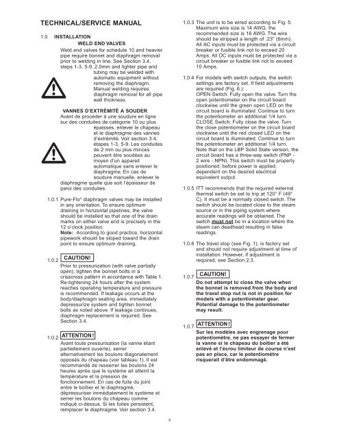
TECHNICAL/SERVICE MANUAL<br />
1.0 INSTALLATION<br />
WELD END VALVES<br />
Weld end valves for schedule 10 and heavier<br />
pipe require bonnet and diaphragm removal<br />
prior to welding in line. See Section 3.4,<br />
steps 1-3, 5-9. 2.0mm and lighter pipe and<br />
tubing may be welded with<br />
automatic equipment without<br />
<br />
removing the diaphragm.<br />
Manual welding requires<br />
diaphragm removal for all pipe<br />
wall thickness.<br />
VANNES D’EXTRÉMITÉ A SOUDER<br />
Avant de procéder à une soudure en ligne<br />
sur des conduites de catégorie 10 ou plus<br />
épaisses, enlever le chapeau<br />
et le diaphragme des vannes<br />
d’extrémité. Voir section 3.4,<br />
<br />
étapes 1-3, 5-9. Les conduites<br />
de 2 mm ou plus minces<br />
peuvent être soudées au<br />
moyen d’un appareil<br />
automatique sans enlever le<br />
diaphragme. En cas de<br />
soudure manuelle, enlever le<br />
diaphragme quelle que soit l’épaisseur de<br />
paroi des conduites.<br />
1.0.1 <strong>Pure</strong>-<strong>Flo</strong> ® diaphragm valves may be installed<br />
in any orientation. To ensure optimum<br />
draining in horizontal pipelines, the valve<br />
should be installed so that one of the drain<br />
marks on either valve end is precisely in the<br />
12 o’clock position.<br />
Note: According to good practice, horizontal<br />
pipework should be sloped toward the drain<br />
point to ensure optimum draining.<br />
1.0.2<br />
1.0.2<br />
CAUTION!<br />
Prior to pressurization (with valve partially<br />
open), tighten the bonnet bolts in a<br />
crisscross pattern in accordance with Table 1.<br />
Re-tightening 24 hours after the system<br />
reaches operating temperature and pressure<br />
is recommended. If leakage occurs at the<br />
body/diaphragm seating area, immediately<br />
depressurize system and tighten bonnet<br />
bolts as noted above. If leakage continues,<br />
diaphragm replacement is required. See<br />
Section 3.4.<br />
ATTENTION !<br />
Avant toute pressurisation (la vanne étant<br />
partiellement ouverte), serrer<br />
alternativement les boulons diagonalement<br />
opposés du chapeau (voir tableau 1). Il est<br />
recommandé de resserrer les boulons 24<br />
heures après que le système ait atteint la<br />
température et la pression de<br />
fonctionnement. En cas de fuite du joint<br />
entre le boîtier et le diaphragme,<br />
dépressuriser immédiatement le système et<br />
serrer les boulons du chapeau comme<br />
indiqué ci-dessus. Si les fuites persistent,<br />
remplacer le diaphragme. Voir section 3.4.<br />
3<br />
1.0.3 The unit is to be wired according to Fig. 5.<br />
Maximum wire size is 14 AWG, the<br />
recommended size is 16 AWG. The wire<br />
should be stripped a length of .23" (6mm).<br />
All AC inputs must be protected via a circuit<br />
breaker or fusible link not to exceed 20<br />
Amps. All DC inputs must be protected via a<br />
circuit breaker or fusible link not to exceed<br />
10 Amps.<br />
1.0.4 For models with switch outputs, the switch<br />
settings are factory set. If field adjustments<br />
are required (Fig. 6.):<br />
OPEN Switch: Fully open the valve. Turn the<br />
open potentiometer on the circuit board<br />
clockwise until the green open LED on the<br />
circuit board is illuminated. Continue to turn<br />
the potentiometer an additional 1/4 turn.<br />
CLOSE Switch: Fully close the valve. Turn<br />
the close potentiometer on the circuit board<br />
clockwise until the red closed LED on the<br />
circuit board is illuminated. Continue to turn<br />
the potentiometer an additional 1/4 turn.<br />
Note that on the LBP Solid State version, the<br />
circuit board has a three-way switch (PNP -<br />
2 wire - NPN). This switch must be properly<br />
positioned, before power is applied,<br />
dependent on the desired electrical<br />
equivalent output.<br />
1.0.5 ITT recommends that the required external<br />
thermal switch be set to trip at 120° F (49°<br />
C). It must be a normally closed switch. The<br />
switch should be located close to the steam<br />
source or in the piping system where<br />
accurate readings will be obtained. The<br />
switch must not be in a location where the<br />
steam can deadhead resulting in false<br />
readings.<br />
1.0.6 The travel stop (see Fig. 1), is factory set<br />
and should not require adjustment at time of<br />
installation. However, if adjustment is<br />
required, see Section 2.3.<br />
1.0.7<br />
1.0.7<br />
CAUTION!<br />
Do not attempt to close the valve when<br />
the bonnet is removed from the body and<br />
the travel stop nut is not in position for<br />
models with a potentiometer gear.<br />
Potential damage to the potentiometer<br />
may result.<br />
ATTENTION !<br />
Sur les modèles avec engrenage pour<br />
potentiomètre, ne pas essayer de fermer<br />
la vanne si le chapeau du boîtier a été<br />
enlevé et l’écrou limiteur de course n’est<br />
pas en place, car le potentiomètre<br />
risquerait d’être endommagé.


