
You also want an ePaper? Increase the reach of your titles
YUMPU automatically turns print PDFs into web optimized ePapers that Google loves.
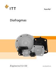
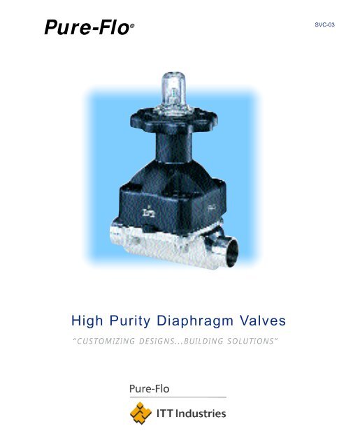
<strong>Pure</strong>-Flo ®<br />
Diaphragm Valves<br />
High Purity Diaphragm Valves<br />
“CUSTOMIZING DESIGNS...BUILDING SOLUTIONS”<br />
SVC-03
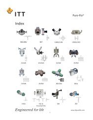
TABLE OF CONTENTS<br />
<strong>Pure</strong>-Flo ® Diaphragm Valves<br />
Products for the Pharmaceutical<br />
and Bioprocessing Industries<br />
Innovation<br />
Features & Benefits<br />
Bodies/Metallurgy<br />
Interior Surface Finishes<br />
End Connections/Body Dimensions<br />
Process Fabrications<br />
Modular Valve Assemblies<br />
Diaphragms<br />
“TM” & #16<br />
Bonnets<br />
PAS Bonnet<br />
Advantage ® Actuators<br />
Dimensional Data<br />
Sizing Charts<br />
Positioner<br />
Dia-Flo Actuators<br />
Dualrange ®<br />
Switches, Advantage Actuator<br />
Manual Bonnet<br />
Hot Lock Out Bonnet Assembly<br />
Specialty Valves<br />
BIO-TEK ®<br />
Swickle<br />
Tank Bottom<br />
Divert Valves<br />
Sterile Tank Vent Filter<br />
Chromatography<br />
Sterile Barrier<br />
General Engineering Data<br />
Compliance, Approvals & Validation Documentation<br />
Figure Numbers<br />
How to Order<br />
2<br />
6<br />
8<br />
10<br />
12<br />
14<br />
21<br />
22<br />
23<br />
24<br />
26<br />
28<br />
33<br />
35<br />
51<br />
50<br />
52<br />
40<br />
46<br />
48<br />
54<br />
56<br />
58<br />
61<br />
64<br />
68<br />
69<br />
70<br />
72<br />
77<br />
80<br />
86<br />
ITT Industries, Engineered Process Solutions<br />
Lancaster, PA
ITT Fluid Technology Corporation, Upper<br />
Saddle River, NJ, USA is a worldwide leader in<br />
fluid management with sales of more than<br />
$2 billion. Products include Valves, Pumps,<br />
Heat Exchangers, Instruments and Controls.<br />
The <strong>Pure</strong>-Flo ® product line is a spin-off of<br />
the process proven Dia-Flo ® Diaphragm Valve<br />
line, now more than 50 years old. The <strong>Pure</strong>-Flo<br />
product line is the recognized leader in the<br />
Pharmaceutical/Bioprocessing Industries for<br />
innovation and quality and is dedicated to<br />
providing product solutions for our clients.<br />
Behind this brochure stands a company<br />
of people committed to innovation, quality,<br />
thoroughness, timeliness and service, with<br />
the ultimate goal of satisfying your needs and<br />
requirements. Please don’t hesitate to contact<br />
us at <strong>Pure</strong>-Flo Solutions Group (PFSG) for solutions<br />
to your most challenging process problems.<br />
We have prided ourselves in listening to you,<br />
the customer, to remain a leader in an everchanging<br />
and dynamic marketplace.<br />
1<br />
WHO WE ARE
2 SOLUTIONS TO PROCESS PROBLEMS<br />
A<br />
s a recognized leader in innovation<br />
for the Pharmaceutical/Bioprocessing<br />
Industries, <strong>Pure</strong>-Flo Solutions Group<br />
(PFSG) prides itself in developing solu-<br />
tions for process problems.<br />
Accomplished through direct client<br />
input, this has, and will continue to be,<br />
our focus. Innovation, however, doesn’t<br />
stop with the product. Innovation also<br />
applies to soft side support such as ser-<br />
vice, manufacturing, a worldwide net-<br />
work of distribution and factory techni-<br />
cal sales representatives, documentation<br />
to assist in validation, internet access,<br />
and software dimensional programs.
3<br />
INNOVATION
4 SOLUTIONS TO PROCESS PROBLEMS
T<br />
he integration of innovative quali-<br />
ty product with soft side support pro-<br />
vides the ideal combination to assist<br />
our customers in accessing, “...the cur-<br />
rent technology available today,” to<br />
meet their needs and requirements in<br />
this dynamic industry. The assemblies<br />
and fabrications on the proceeding<br />
pages have been developed primarily<br />
to minimize contact surfaces and hold<br />
up volume.<br />
5<br />
INNOVATION
6 PURE-FLO ® DIAPHRAGM VALVES<br />
Adjustable Travel Stop<br />
prolongs diaphragm life<br />
Brass Bushing acts as a<br />
lubricant and facilitates<br />
stem operation<br />
Top Entry In-Line<br />
Maintenance<br />
Molded in<br />
Fingers<br />
Floating Tube Nut<br />
Design prevents<br />
stud pull out and<br />
point loading at<br />
diaphragm center<br />
Optional<br />
Hygienic<br />
Internals<br />
Streamlined<br />
Fluid Passage<br />
Optimal Drainability*<br />
Polished surface finishes from 35–11<br />
μin R a (.89–.28 μm. 150–320 grit)<br />
*Schedule 5,10 and 40 buttweld valves are not drainable in a horizontal line.<br />
Protective Cap seals the internals from<br />
atmospheric conditions.<br />
Visual Position Indicator<br />
PTFE and Elastomer<br />
Diaphragms available<br />
Manual and power<br />
actuation available<br />
“O” Ring Furnished<br />
Bonnet standard in<br />
900 series<br />
Bonnet Selection<br />
Fasteners enclosed in<br />
bonnet housing<br />
Weep Hole allows for leak<br />
detection (available with<br />
“V” notch vent plug)<br />
Interior/Exterior Electropolish available
FEATURES BENEFITS<br />
Adjustable Travel Stop: Prevents overclosure of the valve and prolongs diaphragm life. Typically an<br />
option, however, PFSG provides the Adjustable Travel Stop as a standard.<br />
Brass Bushing: Prevents the stem from galling in the bonnet throat during washdown and<br />
autoclave applications.<br />
Body Selection: 316L stainless steel forged bodies, investment cast bodies and wrought<br />
bodies are available<br />
Diaphragm Selection: FDA compliant diaphragms include EPDM, Black Butyl, White Butyl, Buna N,<br />
<strong>Pure</strong> Gum Rubber and PTFE.<br />
Drainability: Permanent hash marks on castings and drain dots on forgings simplify<br />
the orientation of the body to optimize drainability. Refer to the General<br />
Engineering Data section for further information.<br />
Enclosed Fasteners: In the Thermoplastic bonnets, the stainless steel nuts are concealed within<br />
the bonnet housing to provide a smooth washdown surface, free of crevices<br />
and area for fluid entrapment.<br />
Electropolish: Provides a chromium rich, passive surface, and serves as a quality<br />
assurance mechanism revealing surface flaws and weld defects which<br />
mechanical polishing may conceal. Electropolish is available on the interior<br />
or exterior valve surface.<br />
Floating Tube Nut Design: Prevents point loading on the diaphragm stud during closing operations<br />
and hence reduces the chance of stud pull out.<br />
Interior Surface Finishes: Standard surface finishes from as-cast to 11 μin (.28 μm, 320 grit )R a<br />
are available.<br />
Material Tracability: Through a permanently stamped heat number on the exterior valve body,<br />
the material composition can be traced and furnished by requesting<br />
Certified Mill Tests Reports (CMTR).<br />
“O” Ring Furnished Bonnet: Buna N “O” rings are supplied as standard in the 900 series bonnet and<br />
prevent the accumulation of fluids in the bonnet area during washdown<br />
protocols.<br />
Permanent Lubrication: Reduces periodic lubrication and hence maintenance time (FDA compliant).<br />
Position Indicator: A bright yellow visual position indicator is provided as standard.<br />
Protective Cap: Acrylic or Polyphenylsulfone cap prevents atmospheric conditions or<br />
washdown fluids from entering the bonnet internals.<br />
Quality Assurance: Quality is a top priority at ITT and is assured by performing key operations inhouse.<br />
Our quality assurance procedures are available for your review upon<br />
request.<br />
Hygienic Internals: Stainless steel stem, roll pin and bronze compressor are available upon<br />
request.<br />
Sealed Bonnet: A “V” notch vent plug serves as a leak detector and provides a secondary<br />
containment area for process fluids in case of diaphragm failure.<br />
Streamlined Fluid Passage: A smooth, contoured, interior surface with the minimizing of pockets prevents<br />
accumulation of process fluids or contaminants.<br />
Top Entry: Allows the valve to be maintained without removing the body from the<br />
process system, and minimizes downtime.<br />
7<br />
FEATURES AND BENEFITS
8 BODIES/METALLURGY<br />
Size Range<br />
The <strong>Pure</strong>-Flo ® product line offers a complete line of Cast, Forged and Wrought bodies<br />
to meet the needs and requirements of your process application. The size range, dimension-<br />
al standards, as well as stainless alloys available for the various body types are as follows:<br />
Cast Forged Wrought<br />
ANSI 1/2" - 6" Bio-Tek, 1/2"-3" 1/2" - 4"**<br />
DIN/ISO DN 15 - DN 50 DN 8 - DN 50 DN 15 - DN 100 +<br />
316L Stainless Alloy ASTM A351 Grade CF 3M Dual certified to ASTM A479, 316L<br />
ASTM A182 Grade 316L,S9<br />
DIN 17440, 1.4435<br />
Dimensional Standards OD Tubing, Pipe, ISO/DIN OD Tubing, Pipe, OD Tubing, Pipe, ISO/DIN<br />
ISO/DIN/SMS<br />
** 4" <strong>Pure</strong>-Flo bodies, Tank Bottom Valves, divert valves and any block bodied fabrications are standard. 1/2"-3" <strong>Pure</strong>-Flo bodies are nonstandard.<br />
+ DN 65-100 <strong>Pure</strong>-Flo bodies are wrought as standard; sizes DN 15-50 <strong>Pure</strong>-Flo wrought bodies are nonstandard.
MANUFACTURING METHODS<br />
Castings:<br />
<strong>Pure</strong>-Flo bodies are produced utilizing the lost<br />
wax or investment cast method. A wax impression<br />
is created for the shape required. The wax impression<br />
is dipped or sprayed with ceramic material and<br />
then fired in a kiln. The wax evaporates leaving<br />
behind a hard ceramic shell into which molten<br />
material is poured. The solidification of molten<br />
metal may cause sub-surface porosity, which varies<br />
in occurrence depending on casting techniques,<br />
machining and interior finish specifications. The<br />
result is a product complete with flow path, bolt<br />
holes, drain marks and body identification marks<br />
cast into the required shape. Machining is, therefore,<br />
minimal. Ferrite content may vary considerably<br />
depending on several variables including wall thickness,<br />
metallurgy of the material, etc. Engineered<br />
Valves has established a specification of 12% norm<br />
based on ASTM A800 analysis techniques. <strong>Pure</strong>-Flo<br />
Castings go through a rigorous qualification program<br />
to ensure the highest attainable quality is<br />
achieved. The levels of porosity are the absolute<br />
minimum possible.<br />
Forgings:<br />
<strong>Pure</strong>-Flo bodies are produced from round stock<br />
or plate which has been processed from an ingot.<br />
The round stock or plate is compressed between<br />
two halves of a forging tool at elevated temperatures.<br />
The result is a shape which is then machined<br />
to create the shape required. Machining required is<br />
more extensive than a casting. Ferrite content for<br />
the ANSI <strong>Pure</strong>-Flo and ISO/DIN forged product lines<br />
is 0.5%. The ferrite measurement method employed<br />
by Engineered Valves is the more accurate and<br />
labor intensive metalographic technique of ASTM E-<br />
562.<br />
Wrought:<br />
The 4" <strong>Pure</strong>-Flo wrought body, Tank Bottom<br />
Valves, divert valves and block body fabrications are<br />
produced from wrought material. Wrought material<br />
is worked material such as plate or round stock.<br />
Rather than forging a shape between two halves of<br />
a tool, as in the case of a forged body, the shape<br />
required is machined directly from wrought material.<br />
Ferrite content in wrought material may vary<br />
depending primarily on the metallurgy of the material<br />
used; however, most standard product is less<br />
than 3%.<br />
Ferrite:<br />
Ferrite can be defined as the ferromagnetic,<br />
body-centered, microstructural constituent of variable<br />
chemical composition in iron-chromium-nickel<br />
alloys. This may be formed upon solidification from<br />
molten metal (delta ferrite) or by transformation<br />
from austenite or sigma phase on cooling in the<br />
solid state (alpha ferrite). The formation of ferrite is<br />
therefore a natural occurrence in stainless alloy<br />
products. Ferrite levels can be determined utilizing<br />
several techniques including chemical analysis, metalographic<br />
examination and magnetic attraction. As<br />
one can see from the above comparisons, ferrite is<br />
depleted as the material is worked, i.e. castings<br />
having the highest content and forgings having the<br />
lowest. Free delta ferrite contained in components<br />
in a process system may or may not be of concern<br />
to the end user.<br />
The selection of process components in the<br />
Pharmaceutical/Bioprocessing Industry, especially in<br />
cell culture applications, demonstrates a distinct<br />
movement toward lower ferrite materials. It is<br />
important to note, however, in many applications,<br />
the use of higher ferrite content components may<br />
have no effect on the product, nor the service life<br />
and/or performance of the component while reducing<br />
the inherent cost of the component. The nature<br />
of the process, the utility protocols (i.e. passivation,<br />
cleaning, sterilization, fabrication), as well as additional<br />
surface preparation of the material such as<br />
electropolishing, will indeed have a bearing on the<br />
extent of the corrosion resistance of the component.<br />
<strong>Pure</strong>-Flo Solutions Group provides the customer<br />
a choice in body types based on the needs<br />
and requirements of a client’s process application.<br />
9<br />
BODIES/METALLURGY
10 MECHANICAL POLISHING<br />
The method of describing interior surface<br />
finishes for stainless process system<br />
components (i.e., tube, fittings, valves,<br />
etc.) has become more articulate as the<br />
concern for surface quality and consistency<br />
has heightened in the Pharmaceutical<br />
and Bioprocessing Industries.<br />
Initially, interior surfaces were described<br />
by polish numbers such as #4 or #7.<br />
Polish numbers gave manufacturers a<br />
great deal of breadth on the interior finish<br />
supplied. For example: depending on the<br />
polishing technique, a #4 interior finish<br />
may vary from an 80 grit to a 150 grit finish;<br />
a #7 interior finish may vary from a<br />
180 grit to a 320 grit finish.<br />
Polish numbers have been typically<br />
replaced by grit numbers as a means of<br />
describing interior surface finishes more<br />
accurately. Grit numbers have been<br />
defined as the number of silicon carbide<br />
particles per square inch of abrasive pad.<br />
Another definition equates grit number<br />
with the number of scratches per linear<br />
inch. In general, however, grit numbers<br />
attempt to link surface roughness with the<br />
number of scratches on a particular surface.<br />
The higher the grit number, the finer<br />
and more numerous the scratches, the<br />
Specify a maximum surface roughness:<br />
SURFACE ROUGHNESS<br />
Parameter Description Specification Definition Diagram<br />
R a (CLA)<br />
R q (RMS)<br />
Arithmetic DIN 4768/1<br />
means DIN 4762/1<br />
roughness Draft<br />
value ISO/DIS<br />
4287/1<br />
Draft<br />
Root mean DIN 4762/1<br />
square Draft<br />
roughness ISO/DIS<br />
value 4287/1<br />
Draft<br />
smoother the finish. The method of polishing,<br />
the devices employed, and the surface<br />
hardness encountered (i.e., castings,<br />
forgings, extrusions, etc.) all have a bearing,<br />
however, on the surface roughness<br />
achieved. The Pharmaceutical and<br />
Bioprocessing Industries are now applying<br />
a more articulate means of describing surface<br />
roughness. The surface roughness is<br />
actually measured in micro inches, or<br />
microns, by a surface profilometer. Surface<br />
roughness is normally described utilizing<br />
two arithmetic derivations: Rq-root mean<br />
square or R a -arithmetic mean (see below).<br />
Utilizing a quantitative measuring technique,<br />
all the variables inherent in polishing<br />
are eliminated. An end user can now<br />
specify a specific surface roughness, i.e.,<br />
25 µin R a , and the vendor must now<br />
determine how to effectively achieve the<br />
finish required. The result is a consistent,<br />
verifiable surface finish.<br />
<strong>Pure</strong>-Flo Solutions Group utilizes a<br />
Hommelwerke T-20 surface roughness<br />
device as a quality assurance mechanism<br />
and can provide, per request, a tape<br />
detailing the interior surface characterization<br />
of valve bodies on a statistical basis.<br />
ROUGHNESS CHART<br />
Micro Inch Micron Grit #<br />
µ in µ m (Reference only)<br />
35 0.89 150<br />
25 0.64 180<br />
20 0.51 240<br />
11 0.28 320<br />
Note: Values expressed in R a<br />
The arithmetical average value of all absolute distances of the roughness<br />
profile R from the centre line within the measuring length l m .<br />
(An alternative to R a .) R q is defined as the RMS value of a profile<br />
calculated over a single sampling length, but can be expressed as<br />
the mean result of 5 consecutive sampling lengths.
ELECTROPOLISHING<br />
Electropolishing, simply stated, is the<br />
electrochemical method of removing metal<br />
from a surface. Formally, electropolishing is<br />
defined as anodic dissolution in the presence<br />
of an electrolyte and an imposed current<br />
potential.<br />
The inherent benefits derived from electropolishing<br />
are as follows:<br />
• Provides a continuous, tenacious,<br />
chromium-rich oxide layer on the surface<br />
resulting in an excellent passive<br />
film enhancing corrosion resistance<br />
• Surface leveling reduces the total<br />
surface height and relieves much<br />
of the surface tension inherent in<br />
mechanical polishing<br />
• Enhances the optimization of cleanability<br />
and sterilization<br />
• Provides a quality control mechanism<br />
exposing surface pits and defective<br />
welds<br />
• Exposes and removes impurities within<br />
the surface layer<br />
• Provides a lusterous, aesthetically<br />
pleasing appearance.<br />
For the reasons mentioned, the use of<br />
electropolishing over a mechanically polished<br />
surface is becoming more prevalent<br />
on the surfaces of system components in<br />
critical pharmaceutical and bioprocessing<br />
applications.<br />
The <strong>Pure</strong>-Flo product line is available<br />
with electropolished interior and exterior<br />
surfaces, sizes 1/4–6 (DN 8–150).<br />
DIAGRAM OF A TYPICAL ELECTROPOLISHING CELL<br />
LEGEND<br />
a Anode e Heater and Temperature Regulator<br />
b Cathode f Cooling Coil<br />
c Power Source M + Metal Ion<br />
d Electrolyte A – Anion<br />
DIAGRAM ILLUSTRATING<br />
MICROPOLISHING AND MACROPOLISHING<br />
LEGEND<br />
a Region of Macropolishing M + Metal Ion<br />
b Region of Micropolishing A – Anion<br />
11<br />
INTERIOR SURFACE FINISHES
12 END CONNECTIONS/DRAINABILITY<br />
END CONNNECTIONS<br />
<strong>Pure</strong>-Flo Diaphragm Valve bodies are available in a<br />
variety of end connections:<br />
• Tri-Clover Tri-Clamp ®<br />
• Cherry Burrell “S”, “Q”<br />
and “I” line ®<br />
• 14, 16, 18, 20 O.D.<br />
Gauge Tubing<br />
• Schedule 5, 10, 40 Piping<br />
• ISO Ends<br />
• SMS 1146 Ends<br />
• DIN 11850 Ends<br />
• Others upon Request<br />
Standard cutback is 1/2" (1.27 cm) unless otherwise<br />
specified. Maximum cutbacks range up to 1.25" (3.17<br />
cm), dependent upon valve size, and are available<br />
upon request. In addition, tube end extensions of 1.5"<br />
are available to accommodate automatic welding. ISO<br />
ends standard cutback is longer in length and ranges<br />
from 25 mm–35 mm dependent on valve size.<br />
DRAINABILITY<br />
Drain marks are provided as standard on cast and<br />
forged bodies to facilitate installation and optimize<br />
drainability. One mark must be located in the vertical<br />
plane, cutting the centerline of the pipe. Refer to the<br />
General Engineering Data section, page 73, for drain<br />
angles.<br />
The slope of process piping must be designed to provide<br />
proper pitch in order to optimize drainability.<br />
Drainability in a process system is ultimately the<br />
responsibility of the system designer and/or end user.<br />
US & SMS FORGINGS<br />
US & SMS US SMS<br />
END END<br />
CONNECTION CONNECTION TOPWORKS<br />
SIZE INCH SIZE DN SIZE A D B C<br />
20 GA. 18 GA. 16 GA. 14 GA.<br />
0.035" 0.049" 0.065" 0.083"<br />
B C<br />
(0.90) (1.20) (1.65) (2.10)<br />
1/4" DN6 BIOTEK 3.5" (89) 1" (25) .25" (6.4) X X<br />
3/8" DN10 BIOTEK 3.5" (89) 1" (25) .375" (9.5) X X<br />
1/2" DN15 BIOTEK 3.5" (89) 1" (25) .5" (12.7) X X<br />
1/2" DN15 1/2" 3.5" (89) .748" (19) .5" (12.7) X X X X<br />
3/4" DN20 3/4" 4.0" (102) .830" (21) .75" (19.1) X X X X<br />
1" DN25 1" 4.5" (114) .866" (21) 1" (25.4) X X X 25 1.2<br />
1-1/4" DN32 1-1/4" 5.5" (140) .866" (21) 32 1.2<br />
1-1/2" DN40 1-1/2" 5.5" (140) .866" (21) 1.5" (38.1) X X X 38 1.2<br />
2" DN50 2" 6.25" (159) .984" (25) 2" (50.8) X X 51 1.2<br />
2-1/2" + DN65 3" 8.75" (222) 1.162"(29.5) 2.5" (63.5) X 63.5 1.6<br />
3" DN80 3" 8.75" (222) 1.162"(29.5) 3" (76.2) X X 76.1 2.0<br />
4" * DN100 4" 11.5" (292) 1.25" (31) 4" (101.6) X X<br />
* Wrought body is standard.<br />
+ 3" forged body with 2 1/2" end connections.
BODY DIMENSION CHARTS<br />
ISO & DIN<br />
ISO & DIN FORGINGS<br />
ISO DIN SERIES 1 DIN SERIES. 2 DIN SERIES 3<br />
END<br />
CONNECTION<br />
SIZE DN<br />
TOPWORKS<br />
SIZE A D B C<br />
1.0 1.2 1.6 2.0 2.3 2.6 2.9<br />
B C B C B C<br />
DN6 BIOTEK 89 25 8 X X 8 1.0<br />
DN8 BIOTEK 89 25 13.5 X X X 10 1.0<br />
DN10 BIOTEK 89 25 17.2 X X X 12 1.0 13 1.5 14 2.0<br />
DN15 1/2" 106 25 21.3 X X 18 1.0 19 1.5 20 2.0<br />
DN20 3/4" 118 25 26.9 X X 22 1.0 23 1.5 24 2.0<br />
DN25 1" 127 25 33.7 X X 28 1.0 29 1.5 30 2.0<br />
DN32 1-1/2" 174 35 42.4 X X 34 1.0 35 1.5 36 2.0<br />
DN40 1-1/2" 174 35 48.3 X X X 40 1.0 41 1.5 42 2.0<br />
DN50 2" 191 35 60.3 X X X 52 1.0 53 1.5 54 2.0<br />
DN65 * 2 1/2" 229 35 76.1 X 70 2.0<br />
DN80 * 3" 229 35 88.9 X 85 2.0<br />
DN100 * 4" 292 31 114.3 X 10⁴ 2.0<br />
* Wrought body is standard.<br />
ISO CASTINGS<br />
END<br />
CONNECTION TOPWORKS<br />
SIZE DN SIZE A D B C<br />
1.0 1.2 1.6 2.0 2.3 2.6 2.9<br />
DN15 1/2" 106 25 21.3 X X X<br />
DN20 3/4" 118 25 26.9 X X X<br />
DN25 1" 127 25 33.7 X X X X<br />
DN32 1-1/2" 174 25 42.4 X X X X<br />
DN40 1-1/2" 174 35 48.3 X X X X<br />
DN50 2" 191 35 60.3 X X X X<br />
US, SMS & DIN CASTINGS<br />
US, SMS & DIN US SMS DIN SER. 1 DIN SER. 2 DIN SER. 3<br />
END END<br />
CONNECTION CONNECTION TOPWORKS<br />
SIZE INCH SIZE DN SIZE A D B C<br />
20 GA.18 GA.16 GA. 14 GA.<br />
B C B C B C B C<br />
.035" .049" .065" .083"<br />
(.9) (1.2) (1.7) (2.1)<br />
1/2" DN15 1/2" 3.5" (89) .5" (12.7) .5" (12.7) X X X NA NA 18 1.0 19 1.5 20 2.0<br />
3/4" DN20 3/4" 4.0" (102) .5" (12.7) .75" (19.1) X X X X NA NA 22 1.0 23 1.5 24 2.0<br />
1" DN25 1" 4.5" (114) .5" (12.7) 1" (25.4) X X X 25 1.2 28 1.0 29 1.5 30 2.0<br />
1-1/4" DN32 1-1/2" 5.5" (140) .5" (12.7) 32 1.2 34 1.0 35 1.5 36 2.0<br />
1-1/2" DN40 1-1/2" 5.5" (140) .5" (12.7) 1.5" (38.1) X X X 38 1.2 40 1.0 41 1.5 42 2.0<br />
2" DN50 2" 6.25" (159) .5" (12.7) 2" (50.8) X X 51 1.2 52 1.0 53 1.5 54 2.0<br />
2-1/2" DN65 2-1/2" 7.62" (194) .5" (12.7) 2.5" (63.5) X X 63.5 1.6 70 2.0<br />
3" DN80 3" 8.75" (222) .62" (15.9) 3" (76.2) X X 76.1 2.0 85 2.0<br />
4" DN100 4" 11.5" (292) .62" (15.9) 4" (101.6) X X 104 2.0<br />
Tri-Clamp, Quick Disconnect and Buttweld Pipe End Connections are also available.<br />
All units are in mm unless otherwise noted.<br />
The Advantage actuator, Dia-Flo actuator or Dualrange bonnet assembly** can be mounted to the ISO Body.<br />
DN 32 (1 1/4") utilizes DN 40 (1 1/2") sized actuators.<br />
**Available only with Dia-Flo Actuator.<br />
13<br />
END CONNECTIONS/BODY DIMENSIONS
14 PROCESS FABRICATIONS<br />
GMP TM<br />
The GMP fabrication can be utilized to virtually eliminate dead legs in<br />
the design of point-of-use outlets in a typical WFI distribution loop.The<br />
process fluid flows through the valve body. As demand warrants, the<br />
valve is opened, providing an uncontaminated sample untainted by<br />
bacterial growth or contaminants which may accumulate in outlets<br />
greater than 6D. The outlet can also be utilized as a steam condensate<br />
drain or as a divert port. The valve body has been modified to accept a<br />
third port of the same diameter or smaller, positioned adjacent to the<br />
weir at the bottom of the valve. Typically the GMP Valve is oriented in<br />
the vertical position. For horizontal process applications, the sterile<br />
access valve is recommended. The GMP configuration is available in<br />
sizes 1/4"–4" (DN 8–100) and can be supplied with buttweld or ferrule<br />
end connections.<br />
STERILE ACCESS PORTS<br />
The Sterile Access Port provides access to the interior of the valve<br />
body, at the lowest cross sectional point of the waterway, when the<br />
valve body is oriented at the optimum drain angle in a horizontal piping<br />
system.<br />
This port can be furnished as shown utilizing a valve or with various<br />
tube extension lengths and end connections. This Access Port can be<br />
used as a sampling, condensate drain or divert port. This fabrication is<br />
available in 316L stainless steel forgings, 1/4"-3" (DN 8-80) or investment<br />
castings, 2-1/2"-4" (DN 65-100).<br />
STANDARD ZERO STATIC WITH “U” BEND<br />
The Standard Zero Static fabrication is typically oriented as shown<br />
below and has excellent application properties in sampling, draining or<br />
diverting process fluids. The inherent dead leg, defined as the distance<br />
from the tubing/piping centerline to the valve weir, is minimized to<br />
comply with the FDA 6D guidelines in all possible size configurations.<br />
This fabrication is available in 316L stainless steel investment cast<br />
2-1/2"-4" (DN 65-100) or forged valve bodies, sizes 1/4"–2" (DN 8–50).<br />
ZERO STATIC “T” WITH “U” BEND<br />
The Zero Static “T” fabrication is a design modification of the<br />
Standard Zero Static, by significantly reducing the dead leg and area for<br />
product entrapment. The Zero Static “T” fabrication is optimally used in<br />
sampling, draining or diverting applications of critical process fluids.<br />
This fabrication is available in wrought 316L stainless steel 1/2"-2"<br />
valve (DN15-50) by 4" (DN100) header maximum.
PURE-FLO ® GMP ® 15<br />
The GMP (Good Manufacturing Practice) fabrication<br />
reduces dead leg and is traditionally used as a<br />
point-of-use valve.<br />
PURE-FLO ® BIO-TEK ®<br />
PURGE SIZE-BODY OR TUBE<br />
SIZE RANGE<br />
1/4"–4" main valve by 3" maximum<br />
purge (DN 8–100 by main valve by DN 80<br />
maximum purge)<br />
PRESSURE/TEMPERATURE<br />
See General Engineering Data section, page 75.<br />
BODY MATERIAL<br />
• 316L Stainless Steel Forging, ASTM A-182,<br />
1/4"–3" (DN 8–80)<br />
• 316L Stainless Steel Investment Cast, CF3M,<br />
2 1/2"–4" (DN 65–100)<br />
END CONNECTIONS<br />
Buttweld:<br />
• 14, 16, 18, 20 Gauge O.D. Tubing<br />
• Schedule 5, 10, and 40 Pipe<br />
• DIN/ISO Ends<br />
Quick Disconnect:<br />
• Tri-Clover Tri-Clamp ®<br />
• Cherry Burrell “S”, “Q”, and “I” line ®<br />
• Others available upon request<br />
DRAIN MARKS<br />
Drain Dots are provided on forgings.<br />
Hash Marks are provided on investment castings.<br />
Refer to General Engineering Data section<br />
for drainability angles.<br />
Inch 0.25 .375 0.50 0.75 1.00 1.50 2.00 2.50 3.00 4.00<br />
(DN) 4 8 10 15 20 25 40 50 65 80 100<br />
.25, .375,<br />
.50 8, 10, 15 X3 X X<br />
0.50 15 X3 X X<br />
0.75 20 X3 X X X<br />
1.00 25 X3 X3 X X X<br />
1.50 40 X3 X3 X X X X<br />
2.00 50 X3 X3 X X X X X<br />
2.50 65 X2,3 X2,3 X2 X2 X2 X2 X2 X2 3.00 80 X3 X3 X X3X X X X X<br />
4.00 100 X3 X3 X3 X3 X X X X X X<br />
1 Castings available for<br />
bodies 2.50" and larger.<br />
2 2.50" Forged Body<br />
uses 3.00" topworks<br />
with 2.50" ends.<br />
3 Does not comply<br />
with 6D.<br />
4 Chart applies only to<br />
O.D. Tube.<br />
PROCESS FABRICATIONS
16 PURE-FLO ® ZERO STATIC<br />
PURE-FLO ® BIO-TEK ®<br />
The Standard Zero Static*, as shown with “U”<br />
bend, provides minimal dead leg and is commonly<br />
used as a point-of-use valve.<br />
TUBING SIZE<br />
SIZE RANGE<br />
1/4"–3" main valve by 4" tube maximum (DN 8–80 by<br />
main valve by DN 100 tube maximum)<br />
PRESSURE/TEMPERATURE<br />
See General Engineering Data section, page 75.<br />
BODY MATERIAL<br />
• 316L Stainless Steel Forging, ASTM A-182, 1/4"–2"<br />
(DN 8–50)<br />
• 316L Stainless Steel Investment Cast, CF3M,<br />
2-1/2"–4" (DN 65–100)<br />
END CONNECTIONS<br />
Buttweld:<br />
• 14, 16, 18, 20 Gauge O.D. Tubing<br />
• Schedule 5, 10, and 40 Pipe 5<br />
• DIN/ISO Ends<br />
Quick Disconnect:<br />
• Tri-Clover Tri-Clamp ®<br />
• Cherry Burrell “S”, “Q”, and “I” line ®<br />
• Others available upon request<br />
* The Zero Static fabrication is supplied with a tube<br />
spool piece as a standard; “U” Bends are available<br />
upon request.<br />
Inch 0.25 .375 0.50 0.75 1.00 1.50 2.00 2.50 3.00 4.00<br />
(DN) 4 8 10 15 20 25 40 50 65 80 100<br />
.25, .375,<br />
.50 8, 10, 15 X X X X X X X X X X<br />
0.50 15 X X X X X X X X3 0.75 20 X X X X X X X<br />
1.00 25 X X X X X X<br />
1.50 40 X X X X X<br />
2.00 50 X X X X<br />
2.50 65 X2 X2 X2 3.00 80 X X<br />
1 Castings available for<br />
bodies 2.50" and larger.<br />
2 2.50" Forged Body uses<br />
3.00" topworks with 2.50"<br />
ends.<br />
3 Does not comply with 6D.<br />
4 Chart applies only to O.D<br />
tubing.<br />
5 Not available with “U”<br />
bends.
PURE-FLO ® BIO-TEK ® ® PURE-FLO ZERO STATIC “T” 17 17<br />
A<br />
A<br />
The Zero Static “T”* reduces dead legs in a<br />
process system by welding the body directly<br />
into the distribution loop. This process fabrication<br />
is frequently used as a point-of-use valve.<br />
TUBING SIZE<br />
Inch 0.50 0.75 1.00 1.50 2.00 3.00 4.00<br />
(DN) 4 15 20 25 40 50 80 100<br />
.25, .375,<br />
.50 8, 10, 15 X X X X X X X<br />
0.50 15 X X X X X X X<br />
0.75 20 X X X X X X<br />
1.00 25 X X X X X<br />
1.50 40 X X X X<br />
2.00 50 X X X<br />
SIZE RANGE<br />
1/4"–2" main valve by 4" header maximum<br />
(DN 15–50 valve by DN 100 tube maximum)<br />
PRESSURE/TEMPERATURE<br />
See General Engineering Data section, page 75.<br />
BODY MATERIAL<br />
• 316L Stainless Steel Wrought, ASTM-A-479,<br />
1/4"–2" (DN 8–50)<br />
END CONNECTIONS<br />
Buttweld:<br />
• 14, 16, 18, 20 Gauge O.D. Tubing<br />
• DIN/ISO Ends<br />
Quick Disconnect:<br />
• Tri-Clover Tri-Clamp ®<br />
• Cherry Burrell “S”, “Q”, and “I” line ®<br />
• Others available upon request<br />
DIMENSIONAL ENVELOPE<br />
• When utilizing the Advantage actuator,<br />
dimension “H” on page 33 should be used.<br />
• When utilizing manual bonnet assemblies,<br />
dimensional information on pages 26 and 76<br />
should be used.<br />
• For valve body end to end dimensions,<br />
contact the factory.<br />
* The Zero Static “T” fabrication is supplied with a tube<br />
spool piece as a standard; “U” Bend type configurations<br />
are available upon request.<br />
4 Chart applies only to<br />
O.D. tubing.<br />
PROCESS FABRICATIONS
18 ZERO STATIC “T” WITH INTEGRAL SAMPLE VALVE<br />
In addition to the inherent design features of the<br />
Zero Static “T”, the integral sample valve option<br />
assits in providing a more representative sample<br />
of water quality directly at the point-of-use<br />
applications.<br />
Zero Static “T” shown with instrument port<br />
PURE-FLO ® ZERO STATIC “T”<br />
WITH INTEGRAL SAMPLE VALVE<br />
To assist in providing a more representative sample of<br />
water quality directly at a point-of-use application, ITT has<br />
developed a block bodied point-of-use valve fabrication<br />
utilizing an integral sample port. The body is manufactured<br />
from ASTM A479 bar stock for high quality and<br />
ease of fabrication. The block body design permits welding<br />
of tube stubs directly to the exterior of the valve body,<br />
eliminating the need of an interior elliptical weld necessary<br />
when inserting a tube directly through a forged body. In<br />
addition, the integral sample valve is integral to the main<br />
valve assembly, which reduces contact surfaces and volume.<br />
The position of the sample valve to the main valve<br />
body eliminates any question of its conformance to cGMP-<br />
6D requirements while greatly reducing the dead leg to<br />
less than 2D, which is unachievable in other sample valve<br />
orientations.<br />
MATERIALS AND SPECIFICATIONS<br />
• 316L Stainless Steel, ASTM A479 wrought bodies,<br />
<strong>Pure</strong>-Flo main valve sizes 1.0" through 2.0" with 0.5"<br />
Bio-Tek ® integral sample valve.<br />
• Other size integral sample valves are available upon<br />
request, up to size of the main valve.<br />
• Standard ANSI 316L Stainless Tubing up to 4".<br />
• Assembly available with FDA compliant PTFE and<br />
EPDM diaphragms.<br />
• Interior surface finishes available with mechanical<br />
finishes from 11μ in. R a . Electropolish over mechanical<br />
services is also available.<br />
• PAS, stainless steel, nylon coated, PVDF coated or<br />
white epoxy coated manual bonnet assemblies<br />
are available.<br />
• Diaphragm driven pneumatic Advantage Actuators<br />
are available.
PURE-FLO ® ZERO STATIC “T” WITH INSTRUMENT PORT AND SAMPLE VALVE<br />
PURE-FLO ® ZERO STATIC “T” WITH INTEGRAL SAMPLE VALVE<br />
19<br />
PROCESS FABRICATIONS
20 PURE-FLO ® STERILE ACCESS<br />
The Sterile Access Fabrication provides access into<br />
process system through a valve body when the main<br />
valve is in a drainable orientation. This configuration is<br />
ideal for sampling or as a condensate drain port.<br />
PURE-FLO ® BIO-TEK ®<br />
PURGE SIZE-BODY OR TUBE<br />
SIZE RANGE<br />
1/4"–4" main valve by 3" maximum purge<br />
(DN 8–100 main valve by DN 80 maximum purge)<br />
PRESSURE/TEMPERATURE<br />
See General Engineering Data section, page 75.<br />
BODY MATERIAL<br />
• 316L Stainless Steel Forging, ASTM A182, 1/4"–3"<br />
(DN 8–80)<br />
• 316L Stainless Steel Investment Cast, CF3M, 2-1/2"–4"<br />
(DN 65–100)<br />
END CONNECTIONS<br />
Buttweld:<br />
• 14, 16, 18, 20 Gauge O.D. Tubing<br />
• Schedule 5, 10, and 40 Pipe<br />
• DIN/ISO Ends<br />
Quick Disconnect:<br />
• Tri-Clover Tri-Clamp ®<br />
• Cherry Burrell “S”, “Q”, and “I” line ®<br />
• Others available upon request<br />
DRAIN MARKS<br />
Drain Dots are provided on forgings.<br />
Hash Marks are provided on investment castings.<br />
Refer to General Engineering Data section for<br />
drainability angles, page 73.<br />
Inch 0.25 .375 0.50 0.75 1.00 1.50 2.00 2.50 3.00 4.00<br />
(DN) 4 8 10 15 20 25 40 50 65 80 100<br />
.25, .375,<br />
.50 8, 10, 15 X X X<br />
0.50 15 X3 X X<br />
0.75 20 X3 X X X<br />
1.00 25 X3 X X X X<br />
1.50 40 X3 X3 X X X X<br />
2.00 50 X3 X3 X3 X X X X<br />
2.50 65 X2,3 X2,3 X2,3 X2,3 X2 X2 X2 X<br />
3.00 80 X3 X3 X3 X3 X X X X X<br />
4.00 100 X3 X3 X3 X3 X X X X X NA<br />
1 Castings available for<br />
bodies 2.50" and larger.<br />
2 2.50" Forged Body uses<br />
3.00" topworks with<br />
2.50" ends.<br />
3 Does not comply with 6D<br />
.<br />
4 Chart applies only to<br />
O.D. tube.<br />
5 NA - not available
MODULAR VALVE ASSEMBLIES 21<br />
21<br />
The Modular Assemblies reduce contact surfaces,<br />
volume and dimensional envelope while reducing<br />
the cost and logistics of field fabrication.<br />
TOP VIEW<br />
FRONT VIEW<br />
The need to reduce contact surfaces and hold up<br />
volume in process applications in the Pharmaceutical/<br />
Bioprocessing Industries is an ongoing challenge. In additon,<br />
the need to reduce the cost and logistics of field<br />
fabrication, while increasing the simplicity and ease of<br />
construction always provides a formidable challenge. In<br />
response to the need and requirements mentioned<br />
above, custom modular valve assemblies are available to<br />
reduce contact surfaces and hold volume while reducing<br />
the inherent cost of installation. Our trained field sales<br />
personnel can assist in the review of your P&IDs and suggest<br />
possible combinations of valves into modular assemblies.<br />
The result is a cost competitive engineered assembly,<br />
which by design:<br />
• reduces contact surfaces, hold up<br />
volume and dimensional envelopes<br />
• minimizes the cost, logistics and time of field<br />
construction<br />
• reduces weldments<br />
• provides an installation-ready assembly,<br />
pre-tested and qualified by the manufacturer<br />
MATERIALS AND SPECIFICATIONS<br />
• 316L Stainless Steel, ASTM A182 grade F316L,<br />
S9 forgings, sizes 1/4" through 3" and/or ASTM A479<br />
wrought bodies, sizes 1/2" through 4.0".<br />
• Assembly available with FDA compliant PTFE and<br />
EPDM diaphragms.<br />
• Interior surface finishes available with mechanical<br />
finishes from 11μ in. Ra . to 35μ in. Ra . Electropolish<br />
over mechanical services is also available.<br />
• PAS, stainless steel, nylon coated, PVDF coated<br />
or white epoxy coated manual bonnet assemblies<br />
are available.<br />
• Diaphragm driven pnuematic Advantage Actuators<br />
are available.<br />
LEFT VIEW<br />
PROCESS FABRICATIONS
22 DIAPHRAGM SELECTION<br />
<strong>Pure</strong>-Flo ® FDA Compliant Diaphragms shown clockwise:<br />
Buna N Grade P, White Butyl Grade WB, Black Butyl Grade<br />
B, <strong>Pure</strong> Gum Rubber Grade A, EPDM Grade H, PTFE Grade<br />
R-2.<br />
<strong>Pure</strong>-Flo Solutions Group offers a wide variety of<br />
diaphragms which means more versatility at all application<br />
levels. The chart at the bottom lists diaphragms<br />
compliant with FDA Code of Federal Regulations Title<br />
21. All elastomer diaphragms comply with Section<br />
177.2600 of the Code. The PTFE Diaphragm complies<br />
with Section 177.1550 of the Code.<br />
<strong>Pure</strong>-Flo Solution Group’s two-piece PTFE Diaphragms<br />
have proven through years of outstanding service to<br />
be the best design available. The two-piece construction<br />
eliminates the delamination problems inherent in<br />
competitive “PTFE faced” diaphragms.<br />
DIAPHRAGM COMPLIANCE<br />
DIAPHRAGM FDA USDA 3A<br />
Soft Rubber � �<br />
Black Butyl � �<br />
EPDM(16) �<br />
EPDM(H) � � � **<br />
Buna N � � � **<br />
White Butyl � �<br />
R-2 PTFE � � � *<br />
TM PTFE �<br />
* Class I applications<br />
** Class III applications<br />
Floating Tube Nut:<br />
The floating tube nut design assures that downward<br />
closing forces will be absorbed by the elastomer backing<br />
cushion and evenly distributed across the closing<br />
surface (weir) in the valve body. The result is reduced<br />
cold flow, drop tight closure and longer diaphragm<br />
life. This reduces point loading of the diaphragm and<br />
eliminates stud pull out.<br />
R-2 PTFE Diaphragm Assembly:<br />
Available in sizes 1/4"–10" (DN 8–250).<br />
Maximum temperature rating of 350°F (176°C).<br />
TM PTFE Diaphragm Assembly:<br />
Available in sizes 1/4"–6" (DN 8–150).<br />
Maximum temperature rating of 350°F (176°C).<br />
DIAPHRAGM TYPE SIZE TEMPERATURE<br />
GRADE MATERIAL INCH DN °F °C<br />
A <strong>Pure</strong> Gum Rubber 3/4–4 20–100 -20–160 -29–71<br />
B Black Butyl Rubber 1/2–12 15–300 -20–250 -29–121<br />
16 EPDM 1/4–4 8–100 -30–300 -34–149<br />
H EPDM 1/4–6 8–100 -30–300 -34–149<br />
P Buna N 1/2–12 15–300 10–180 -12–82<br />
TM PTFE 1/4–6 8–150 -30–350 -34–176<br />
R-2 PTFE 1/4–10 8–250 -30–350 -34–176<br />
WB White Butyl Rubber 1/2–8 15–200 0–225 -18–107
“TM” & #16 DIAPHRAGMS<br />
The introduction of the grade“TM” PTFE and grade<br />
#16 EPDM diaphragms provides the end user<br />
with newest technology in diaphragm compounds<br />
which more aptly resolve the performance issues in<br />
Pharmaceutical/ Bioprocessing process applications.<br />
PURE-FLO ® “TM” PTFE DIAPHRAGM<br />
The “TM” compound is second generation polytetraflouroethylene<br />
(PTFE) polymer modified with a comonomer<br />
PPVE (perflouropropylvinylether). The TM<br />
compound conforms with 21 CFR 177.1550, (a) and<br />
is classified as a PTFE homopolymer according to ISO<br />
12086, as well as ASTM D-4894. This classification is<br />
applicable since the degree of modification is less<br />
than 1%, resulting in:<br />
• More Amorphous Compound – increased flex life<br />
and better mechanical properties<br />
• Reduced Melt Viscosity – slightly lower density<br />
provides greater particle bonding and adhesion<br />
during sintering, more homogeneous microstructure,<br />
smoother surfaces and fewer voids, resulting<br />
in less permeation<br />
• Reduced Creep – reduced cold flow, similar to 25%<br />
carbon reinforced PTFE, less permanent deformation<br />
when subjected to pressure and temperature<br />
In short, the “TM” PTFE diaphragm provides greater<br />
dimensional stability, longer flex life, lower porosity,<br />
lower permeability, superior thermo-mechanical performance<br />
and is tougher and more durable. In addition,<br />
to assist in the qualification of the compound,<br />
USP XXIII Class VI biological reactivity data, sections<br />
#87 and #88 (in vitro and in vivo, respectively) have<br />
been generated by a third party independent lab. This<br />
data is available upon your request.<br />
PURE-FLO GRADE #16 EPDM<br />
DIAPHRAGM<br />
The grade #16 compound complies with 21 CFR<br />
177.2600 and conforms to USP XXVI Class VI biological<br />
reactivity test sections #87 and #88 in vitro and in<br />
vivo, respectively. The compound is comprised of a<br />
high molecular weight terpolymer elastomer which<br />
provides increased mechanical properties while reducing<br />
compression set. In addition, the diaphragm is<br />
peroxide cured rather than sulfur cured enhancing the<br />
biocompatibility of the material.<br />
MATERIALS AND SPECIFICATIONS<br />
“TM” PTFE Diaphragm<br />
• Two piece PTFE diaphragm with #16 EPDM backing<br />
cushion.<br />
• Diaphragm manufactured utilizing sintering process<br />
to increase dimensional stability and flex life.<br />
• Maximum Temperature Rating: 350°F, consult<br />
factory for steam applications.<br />
• Compound complies to 21 CFR 177.1550, (a).<br />
• Compound conforms to test requirements as<br />
outlined in USP XXIII Class VI Biological Reactivity<br />
Tests section #87 and #88.<br />
Grade #16 EPDM Diaphragm<br />
• Peroxide cured.<br />
• Maximum Temperature Rating: 300°F, consult<br />
factory for steam applications.<br />
• Compound complies to 21 CFR 177.2600.<br />
• Compound conforms to test requirements as<br />
outlined in USP XXVI Class VI Biological Reactivity<br />
Tests section #87 and #88.<br />
23<br />
DIAPHRAGMS
24 BONNETS FEATURES<br />
STANDARD BONNET FEATURES<br />
OPTIONAL BONNET FEATURES<br />
900 Series Bonnet<br />
<strong>Pure</strong>-Flo ® 900 series bonnets include Thermoplastic polyarylsulfone (PAS),<br />
stainless steel, bronze, white epoxy, Nylon and Kynar ® PVDF coated cast iron.<br />
The following features are supplied as standard:<br />
• “O” Ring Furnished<br />
• Adjustable Travel Stop<br />
• Protective Cap<br />
• Brass Stem Bushing<br />
• Visual Position Indicator<br />
• Permanent Lubrication<br />
• Cast Iron or Zinc Compressor<br />
• Cast/molded fingers or separate fingerplates internal to the bonnet, to support<br />
the diaphragm when exposed to high service line pressure.<br />
Thermoplastic PAS Bonnets<br />
The Thermoplastic bonnet is manufactured from PAS, polyarylsulfone, and<br />
serves as a universal bonnet based on the following inherent features:<br />
• Tested and process proven continuous maximum temperature is<br />
300°F (149°C) 1<br />
• PAS (polyarylsulfone) as well as all assembly components are FDA compliant<br />
• The Thermoplastic PAS material is inherently scratch and corrosion resistant<br />
• The PAS bonnet is ideally suited for typical cleaning and sterilization protocols<br />
• The fasteners are enclosed in the bonnet housing to eliminate any area for<br />
fluid entrapment during washdown procedures in sizes 1/2"–3" (DN 15–80)<br />
• Autoclavable models are available in sizes 1/2"–4" (DN 15–100)<br />
• The entire line of PAS bonnets is available in sizes 1/2"–4" (DN 15–100)<br />
• Molded fingers internal to the bonnet support the diaphragm when<br />
exposed to high service line pressure<br />
Sealed Bonnets<br />
A sealed bonnet provides a secondary containment area for process fluids if<br />
the diaphragm should ever fail. A “V” notch vent plug is provided to serve as<br />
a leak detector and prevents the release of process fluids into the atmosphere.<br />
In addition, the bonnet stem is automatically upgraded to stainless steel and<br />
an EDPM gasket is provided where fingerplates exist. Sealed bonnets are an<br />
available option on all manual and automated valve assemblies.<br />
Hygienic Internals<br />
Hygienic Internals are available upon request and include:<br />
• Stainless Steel Stem and Roll Pin<br />
• Stainless Steel Fingerplate (when applicable w/ S.S. bonnets)<br />
• Bronze Compressor<br />
1 Refer to Product Data Sheet for clarification.
BONNETS<br />
SIZE RANGE<br />
1/2"–4"(DN 15–100)<br />
BONNET<br />
Thermoplastic PAS<br />
Bonnet<br />
• Standard<br />
• Sealed<br />
• Hygienic Internals<br />
• Hygienic Internals, Sealed<br />
• Sealed, Autoclavable<br />
• Sealed, Hygienic<br />
Internals, Autoclavable<br />
Stainless Steel Bonnet<br />
• Standard<br />
• Sealed, Autoclavable<br />
• Sealed, Hygienic Internals<br />
• Sealed, Hygienic<br />
Internals, Autoclavable<br />
OPTIONS<br />
Coatings 1<br />
• Atmospheric White Epoxy<br />
• Black Nylon<br />
• PVDF<br />
Sealed Bonnet<br />
A “V” notch vent plug is provided as a leak detector.<br />
It also prevents atmospheric contamination in case<br />
of diaphragm failure. In addition, the bonnet stem<br />
is upgraded to stainless steel.<br />
Hygienic Internals<br />
• Stainless Steel Stem<br />
• Stainless Steel Roll Pin<br />
• Bronze Compressor<br />
3A Bonnet<br />
• PVDF Option<br />
• Stainless Steel<br />
CI Iron or Ductile 2 Iron<br />
Bonnet<br />
• Standard<br />
• Sealed<br />
• Hygienic Internals<br />
• Hygienic Internals,<br />
Sealed<br />
Autoclavable:<br />
• Stainless Steel or PAS<br />
• Select Sealed Bonnet, Viton Seals, PPS CAP<br />
1<br />
Handwheel is Thermoplastic PAS (polyarylsulfone) with coating<br />
to match bonnet.<br />
2<br />
Handwheel is thermoplastic PAS (polyarylsulfone).<br />
25<br />
BONNETS
26 THERMOPLASTIC PAS BONNET<br />
Capable of withstanding steam sterilization temperatures<br />
and typical washdown media, the PAS bonnet is<br />
the compact, lightweight and future standard for critical<br />
process systems.<br />
"B"<br />
"C"<br />
"A" Dia<br />
"D"<br />
SIZE RANGE<br />
1/2"–4"(DN 15–100)<br />
PRESSURE/TEMPERATURE<br />
See General Engineering Data section, page 75.<br />
External Temperature:<br />
300°F (149°C) for models 963-S2-M17<br />
212°F (100°C) for models 963, M17*<br />
175°F (82°C) for models 963, +<br />
Bonnet Material<br />
• Thermoplastic Polyarylsulfone (PAS)<br />
• FDA Compliant<br />
CORROSION RESISTANCE<br />
Excellent against alcohol, chloride and caustic washdowns.<br />
For specific chemical resistance, consult the factory.<br />
AUTOCLAVABLE<br />
Models 963S-S2-M17-M2 ³<br />
ENCLOSED FASTENERS<br />
Standard in 1/2"–3" (DN 15–80). Enclosed fasteners<br />
facilitate washdowns.<br />
* Temperature limitation is Buna N “O” rings<br />
+ Temperature limitation of acrylic cap (175°F, 80°C)<br />
° Full temperature capability achievable with PPS cap.<br />
³ Optional hygienic intervals.<br />
VALVE SIZE A B C D<br />
Inch DN Inch cm Inch cm Inch cm Inch cm<br />
0.50 15 3.00 7.62 3.77 9.58 2.80 7.11 3.50 8.89<br />
0.75 20 3.00 7.62 4.68 11.89 3.46 8.79 4.00 10.16<br />
1.00 25 3.00 7.62 5.65 14.35 4.23 10.74 4.50 11.43<br />
1.50 40 5.50 13.97 8.43 21.41 5.33 13.54 5.50 13.97<br />
2.00 50 5.50 13.97 9.07 23.04 5.98 15.19 6.25 15.87<br />
2.50 65 7.75 19.68 11.75 29.84 7.67 19.48 8.75 22.22<br />
3.00 80 7.75 19.68 11.75 29.84 7.67 19.48 8.75 22.22<br />
4.00 100 10.00 25.40 14.66 37.24 10.00 25.40 11.50 29.21
MODULAR VALVE ASSEMBLIES<br />
LIST OF PARTS<br />
ITEM DESCRIPTION MATERIAL QUANTITY<br />
1 1 Bonnet Polyarylsulfone 1<br />
2 Handwheel Polyarylsulfone 1<br />
3 Cap Acrylic, Clear 1<br />
Cap Polyphenylsulfone, Clear 1<br />
42 Spindle Carbon Steel 1<br />
5 Bushing Brass, B-21, Alloy 485 1<br />
63 Nut, Hex Stn. Stl. SA-194-8 4<br />
73 Body, Tank Bottom Stn. Stl. SA-479-316L 1<br />
83 Bearing, Thrust Stn. Stl. A-167, Type 302 1<br />
9 Washer, Shim Polyethylene AR<br />
10 Seal, Wiper Viton 1<br />
Seal, Wiper Polyolefin Foam 1<br />
11 Pin, Spirol Stn. Stl. Type 302 1<br />
12 Scr, Set Hex Soc. Stn., Stl.1 or 2<br />
133 Stud Stn., Stl., SA-193-B8 4<br />
14 Washer, Plain Stn., Stl., 18-8 4<br />
15 Washer Stn., Stl., Type 304 1<br />
16 Locknut, Hex, Lt Stn., Stl., 18-8 4<br />
17 Nut, Hex Stn., Stl. 18-8<br />
18 Cap, Nut Cover Polyarylsulfone 4<br />
19 Spacer Stainless Steel 4<br />
20 Plug, Vent “V” Notch Stn. Stl. A-582, Type 304 1<br />
21 Compressor Zinc or Cast Iron 1<br />
22 Nut, Tube Brass, B-16 1<br />
23 Cushion, Backing EPDM 1<br />
24 Diaphragm, PTFE PTFE, GR, R-2 1<br />
25 “O” Ring Buna N or Viton 1<br />
26 “O” Ring Buna N or Viton 1<br />
27 “O” Ring Buna N or Viton 1<br />
28 Body, Metal Stn. Stl. 316L 1<br />
29 Scr., Hex HD, Cap Stn. Stl. 18-8 4<br />
SANITARY INTERNALS<br />
ITEM DESCRIPTION MATERIAL QUANTITY<br />
4 Spindle Stn. Stl. A-582, Type 303 1<br />
21 Compressor Bronze, B-62 1<br />
Notes:<br />
1. Other bonnet materials available as listed on page 25.<br />
2. Spindle is stainless steel for sealed bonnets.<br />
3. ASME Grade fasterners available only on Tank Bottom Valve.<br />
BONNET AND BOLTING DETAIL FOR<br />
FABRICATIONS WITH STUDS<br />
V-NOTCH VENT PLUG<br />
FOR SEALED BONNET<br />
20<br />
27<br />
BONNETS
28 ADVANTAGE ® ACTUATORS<br />
The Advantage is a diaphragm driven, compact, lightweight actuator designed to meet the stringent space<br />
constraints of the Bioprocessing and Pharmaceutical Industries. The unit is designed as an on/off pneumatic<br />
actuator available with three modes of closure to be utilized on valve sizes 1/4"–4" (DN 8–100).
DIAPHRAGM DRIVEN<br />
Diaphragm-driven type actuators are recognized in the<br />
industry for longevity of service, increased sensitivity to<br />
control pressure variation and more stability and forgiveness<br />
under varying environmental temperatures.<br />
SMALL DIMENSIONAL ENVELOPE<br />
Facilitates ease of installation/maintenance and eliminates<br />
the requirement for additional support of the<br />
actuator. The actuator design provides the same<br />
dimensional envelope regardless of operation mode.<br />
THERMOPLASTIC COVERS<br />
The l/4"–2" (DN 8–50) Advantage actuator is molded<br />
from Thermoplastic polyarylsulfone (PAS). PAS is warranted<br />
to temperatures up to 300°F (149°C), is FDA<br />
compliant and is capable of withstanding caustic,<br />
chloride and alcohol washdowns.<br />
VISUAL INDICATION<br />
The Advantage actuator provides a visual indication of<br />
the valve position.<br />
DIAPHRAGM SELECTION<br />
The Advantage is designed to provide positive closure<br />
with either FDA compliant elastomer or a two-piece<br />
PTFE body diaphragm. Two piece PTFE diaphragms are<br />
more durable by design than PTFE faced diaphragms.<br />
The result is increased reliability, higher cycle and<br />
longer life.<br />
FLOUROPOLYMER “O” RING<br />
FURNISHED<br />
The “O” ring prevents cleaning and sterilizing solutions<br />
from migrating into the actuator causing premature<br />
component failure.<br />
AIR INLET CONNECTION<br />
The air inlet connections to the Advantage actuator<br />
are positioned parallel to the piping system which<br />
enhances close racking of piping. The design of the<br />
inlet ports insures zero leakage to the atmosphere.<br />
AUTOCLAVABLE<br />
The Advantage actuator is autoclavable in sizes 1/4"–2"<br />
(DN 8–50).<br />
ADJUSTABLE OPENING STOP<br />
Optional on the 1/2"–2" (DN 15–50), the Adjustable<br />
Opening Stop is an externally adjustable device which<br />
can limit the opening of the valve.<br />
OPTIONAL SEALED BONNET<br />
A “V” notch vent plug serves as a leak detector and<br />
provides a secondary containment area in the case of<br />
diaphragm failure. This is furnished upon ordering a<br />
Sealed Bonnet.<br />
Advantage ® is a registered trademark of ITT Industries,<br />
Engineered Process Solutions Group.<br />
29<br />
ACTUATION
30 3”–4” PURE-FLO ® SERIES 33 ADVANTAGE ® ACTUATORS<br />
The new 3"–4" <strong>Pure</strong>-Flo 33 Series Advantage Actuators<br />
have been introduced to further reduce the dimensional<br />
envelope and weight for installations in the Pharmaceutical/<br />
Bioprocessing Industries. As an example, a 4" Spring to<br />
Close <strong>Pure</strong>-Flo Advantage Actuator is 25% smaller in diameter,<br />
has 22% reduction in height and offers a 32% reduction<br />
in weight than a comparable 4" commercial Advantage<br />
Actuator, while incorporating many of the same inherent<br />
design features and benefits of the process proven 1/4"<br />
through 2" <strong>Pure</strong>-Flo Advantage Actuator product line.<br />
MATERIALS AND SPECIFICATIONS<br />
• FDA compliant housing and bonnet coating<br />
Actuator Covers<br />
- Vinyl-Ester Thermoset<br />
Bonnet Coatings<br />
- Nylon Coated Ductile Iron - Standard<br />
- PVDF Coated Ductile Iron - Optional<br />
- Black Epoxy Coated Ductile Iron - Optional<br />
• Diaphragm driven Actuator<br />
• Three modes of actuation available:<br />
double acting, spring to open, spring to close<br />
• Reverse Acting Springs are contained for safety and<br />
to facilitate maintenance<br />
• Two Spring options for reverse acting actuators,<br />
i.e. #60 and #90<br />
• Maximum External Temperature – 150°F, 65°C<br />
• Maximum Air Chamber Pressure – 90 psig, 6.2 bar<br />
• Exterior materials compatible with typical washdowns<br />
in the industry<br />
• Position indication<br />
• SP#2 switch package – optional<br />
• Moore Positioner – optional
3”–4” SERIES 47 ADVANTAGE ® ACTUATORS 31<br />
Similar to the smaller valve sized Advantage actuators, the<br />
3"–4" Series 47 (DN 80–100) actuator is also diaphragm<br />
driven, “O” ring furnished and available in three modes of<br />
operation. The actuator design features the same dimensional<br />
envelope regardless of operation mode.<br />
THERMOSET COVERS<br />
The 3"–4" (DN 80–100) is molded from a vinyl ester<br />
thermoset plastic. The bonnet is nylon coated ductile<br />
iron. Both are FDA compliant and capable of withstanding<br />
caustic, chloride and alcohol washdowns.<br />
VISUAL INDICATION<br />
As seen through the transparent acrylic cap, the stem<br />
nut provides visual indication of the valve position.<br />
DIAPHRAGM SELECTION<br />
All <strong>Pure</strong>-Flo Valve body diaphragms are suitable for<br />
operation with the 3"–4" (DN 80–100) Advantage actuator.<br />
SAFETY DEVICE<br />
Due to the thrust forces of the 3"–4" (DN 80–100)<br />
Advantage actuator, the “fail closed” spring package is<br />
self- contained by two ductile iron plates to ensure operator<br />
safety during disassembly operations.<br />
ADJUSTABLE OPENING STOP<br />
Standard on the 3"–4" (DN 80–100) Advantage actuator,<br />
the Adjustable Opening Stop is an externally adjustable<br />
device which can limit the opening of the valve.<br />
ADJUSTABLE TRAVEL STOP<br />
Prevents the diaphragm from overclosing and hence prolongs<br />
the diaphragm life. Given the closing force of the<br />
3"–4" (DN 80–100) Advantage actuators, the Adjustable<br />
Travel Stop is furnished as standard.<br />
MANUAL OVER-RIDE<br />
Enables the actuator to be operated manually in case of<br />
power loss or system failure and is provided as a standard<br />
on the 3"–4" (DN 80–100) Advantage actuator.<br />
ACCESSORIES<br />
All Advantage actuator sizes are available with our<br />
Switch Package, SP 2 or a close coupled positioner<br />
design featuring the Moore positioner. The two cannot<br />
be utilized in conjunction on the same valve. For further<br />
details refer to the following pages and Product Data<br />
Sheet section.<br />
ACTUATION
32 ADVANTAGE ® ACTUATORS<br />
A compact, lightweight plastic, pneumatic, diaphragm<br />
driven actuator ideal for the automatic closing and<br />
opening of the <strong>Pure</strong>-Flo Diaphragm Valve.<br />
SIZE RANGE<br />
1/4"–4" (DN 8–100)<br />
MODE OF OPERATION<br />
Diaphragm driven, Pneumatically operated.<br />
AIR PRESSURE/EXTERNAL<br />
TEMPERATURE<br />
1/4"–2" (DN 8–50)<br />
• 90 psi at 300°F (6,2 bar at 149°C)<br />
3"–4" (DN 80–100)<br />
• 90 psi at 150°F (6,2 bar at 65°C)<br />
ACTUATOR MATERIAL<br />
• Polyarylsulfone (PAS) Thermoplastic,<br />
1/4"–2" (DN 8–50)<br />
• Vinyl Ester thermoset plastic housing and nylon<br />
coated ductile iron bonnet 3"–4" (DN 80–100) All<br />
materials are FDA compliant.<br />
AUTOCLAVABLE<br />
1/4"–2", (DN 8–50)<br />
ACCESSORIES<br />
• Advantage Switch Pack, SP 2, SP 2.5, SP 3.0<br />
• Moore Positioner<br />
OPTIONS<br />
Adjustable Opening Stop<br />
• Externally Adjustable—Standard on 3"–4" (DN<br />
80–100) Series 47<br />
Hygienic Internals<br />
• Stainless Steel Roll Pin<br />
• Bronze Compressor<br />
Sealed<br />
• “V” notch vent plug provides a leak detection<br />
port and prevents process fluids from atmospheric<br />
exposure in case of diaphragm failure.
MODULAR VALVE ASSEMBLIES<br />
AIR TO OPEN—AIR TO CLOSE<br />
SPRING TO OPEN—AIR TO CLOSE, FAIL OPEN<br />
1 Bio-Tek Valve series 2 Buttweld is 3.50"<br />
LIST OF PARTS 1/4"—2", DN 8—50<br />
ITEM DESCRIPTION MATERIAL QUANTITY<br />
1 Cover, Upper Actuator PAS, Cmpl with FDA Cfr #21 1<br />
2 Cover, Lower Actuator PAS, Cmpl with FDA Cfr #21 1<br />
3 Spindle, Valve S.S., ASTM A-582, Type 303 1<br />
4 Diaphragm, Actuator Buna N 1<br />
5 Plate, Actuator S.S. or Car Stl Nickel Pl. 2<br />
6 Spindle, Indicating S.S., ASTM A-582, Type 303 1<br />
7 Spring S.S., ASTM A-401 Nickel Pl. 1<br />
8 Spring S.S., ASTM A-401 Nickel Pl. 1<br />
9 “O” Ring* Viton, Cmpl with FDA Cfr #21 2<br />
10 Body, Weir 1/4"–2" S.S., Forge, or Inv. Cast 1<br />
11 Compressor S.S., C.I. Zinc or Bronze 1<br />
12 Diaphragm, Elastomer* EPDM, Cmpl with FDA Cfr #21 1<br />
13 Diaphragm, Plastic* TFE Cmpl with FDA Cfr #21 1<br />
14 Cushion, Backing* EPDM, Cmpl with FDA Cfr #21 1<br />
*Recommended spare parts<br />
AIR TO OPEN—SPRING TO CLOSE, FAIL CLOSED<br />
HEIGHT WITH ADAPTER SPOOL ADJUSTABLE OPENING STOP<br />
DIMENSIONAL DATA<br />
A B<br />
VALVE SIZE VALVE WITH LIMIT C D E H<br />
OPEN SWITCH, SP 2<br />
Inch DN Inch mm Inch mm Inch mm Inch mm Inch mm Inch mm<br />
.25,.375,.51 8,10,151 4.27 108 9.40 239 2.84 72 2.50 63 2.532 64 Consult Factory<br />
0.50 15 4.89 124 9.93 252 3.34 85 3.00 76 3.50 89 6.39 162<br />
0.75 20 5.93 150 10.92 277 4.56 116 3.88 98 4.00 101 7.38 187<br />
1.00 25 6.55 166 11.35 288 4.56 116 3.88 98 4.50 114 7.94 202<br />
1.50 40 10.62 270 14.97 380 6.41 163 5.94 151 5.50 140 11.86 301<br />
2.00 50 11.39 289 15.41 391 6.41 163 5.94 151 6.25 159 12.56 319<br />
33<br />
ACTUATION
34 ADVANTAGE ® ACTUATOR<br />
SERIES 47 SERIES 33<br />
“A”<br />
1/4” NPT<br />
SERIES 47 DIMENSIONAL DATA<br />
VALVE SIZE A<br />
B<br />
WITH LIMIT<br />
SWITCH, SP 2<br />
C D E F G<br />
Inch DN Inch mm Inch mm Inch mm Inch mm Inch mm Inch mm Inch mm<br />
3 80 21.39 543 26.97 685 14.00 356 14.00 356 8.75 222 10.30 262 7.10 180<br />
4 100 22.50 571 28.09 714 14.00 356 14.00 3561 11.50 292 11.40 290 8.19 208<br />
SERIES 33 DIMENSIONAL DATA<br />
VALVE SIZE A B C D E F<br />
Inch DN Inch mm Inch mm Inch mm Inch mm Inch mm Inch mm<br />
3.00 80 8.75 222.3 7.48 190 10.32 262.1 14.30 363.2 19.96 507 10.57 268.5<br />
4.00 100 11.50 292.1 8.58 217.9 11.40 289.6 15.38 390.7 21.04 534.4 10.57 268.5<br />
“F”<br />
Ø “F”<br />
“A”<br />
“A”<br />
1/2”NPT 1/2” NPT<br />
TYP2 TYP 2<br />
PLACES<br />
0.83<br />
0.83<br />
1/4”<br />
NPT<br />
“B”<br />
“C”<br />
“D”<br />
“D”<br />
“E”
ADVANTAGE ® ACTUATOR A100<br />
DIRECT ACTING ACTUATORS—AIR-TO-CLOSE, SPRING-TO-OPEN, FAIL-OPEN METAL BODIES<br />
PTFE* ELASTOMER DIAPHRAGM<br />
ACTUATOR SIZE SELECTION<br />
Air Pressure Required to Close (psig, bar)<br />
Valve Size Bio-Tek** 0.50 0.75 1.00 1.50 2.00 3.00 4.00 3.00 4.00<br />
Bio-Tek** 15 20 25 32–40 50 80 100 80 100<br />
Actuator Model A103 A105 A108 A108 A116 A116 A133 A133 A147 A147<br />
Line Pressure % �P<br />
psig/bar 100 0 100 0 100 0 100 0 100 0 100 0 100 0 100 0 100 0 100 0<br />
20 38 40 38 45 38 55 28 40 36 40 40 45 44 46 48 55 32 37 30 40<br />
1.38 2.62 2.76 2.62 3.10 2.62 3.79 1.93 2.76 2.48 2.76 2.76 3.10 3.03 3.17 3.31 3.79 2.21 2.55 2.07 2.76<br />
40 40 42 40 50 42 60 32 45 38 44 45 50 50 58 55 69 41 44 36 47<br />
2.76 2.76 2.90 2.21 3.45 2.70 4.14 2.21 3.10 2.62 3.03 3.10 3.45 3.45 4.00 3.79 4.76 2.83 3.03 2.48 3.24<br />
60 42 44 44 55 46 65 36 55 42 48 50 60 55 66 64 85 42 49 42 56<br />
4.14 2.90 3.03 3.03 3.79 3.17 4.48 2.48 3.79 2.90 3.31 3.45 4.14 3.79 4.55 4.41 5.86 2.90 3.38 2.90 3.86<br />
80 46 48 48 60 50 70 40 60 44 52 56 70 61 76 72 90 44 56 48 66<br />
5.52 3.17 3.31 3.31 4.14 3.45 4.83 2.76 4.,14 3.03 3.59 3.86 4.83 4.21 5.24 4.97 6.21 3.03 3.86 3.31 4.55<br />
100 48 52 50 65 52 75 45 70 48 56 60 75 66 90 80 — 52 65 53 79<br />
6.90 3.31 3.59 3.45 4.48 3.59 5.17 3.10 4.83 3.31 3.86 4.14 5.17 4.55 6.21 5.52 — 3.59 4.48 3.65 5.45<br />
125 52 56 54 70 60 85 50 75 50 60 64 80 78 — 90 — 63 73 59 90<br />
8.62 3.59 3.86 3.72 4.83 4.14 5.86 3.45 5.17 3.45 4.13 4.41 5.52 5.38 — 6.21 — 4.34 5.03 4.07 6.21<br />
150 56 60 58 75 68 — 55 85 52 65 68 — 81 — — — 71 83 65 —<br />
10.34 3.86 4.14 4.00 5.17 4.70 — 3.79 5.86 3.59 4.48 4.69 — 5.59 — — — 4.90 5.72 4.48 —<br />
20 42 50 46 66 55 55 50 55 45 52 48 50 64 60 78 80 36 53 46 48<br />
1.38 2.90 3.45 3.17 4.55 3.79 3.79 3.45 3.79 3.10 3.59 3.31 3.45 4.41 4.14 5.38 5.52 2.48 3.65 3.17 3.31<br />
40 44 52 50 68 58 60 55 60 50 56 50 60 68 78 84 90 44 60 52 66<br />
2.76 3.03 3.59 3.45 4.70 4.00 4.14 3.79 4.14 3.45 3.86 3.45 4.14 4.69 5.38 5.79 6.21 3.03 4.14 3.59 4.55<br />
60 48 56 52 72 60 65 60 65 55 60 56 70 74 88 90 — 51 75 56 74<br />
4.14 3.31 3.86 3.59 4.97 4.14 4.48 4.14 4.48 3.79 4.14 3.86 4.83 5.10 6.07 6.21 — 3.52 5.17 3.86 5.10<br />
80 52 60 56 76 65 70 65 70 60 64 64 80 78 — — — 55 85 62 81<br />
5.52 3.59 4.14 3.86 5.24 4.48 4.83 4.48 4.83 4.14 4.41 4.41 5.52 5.38 — — — 3.79 5.86 4.27 5.58<br />
100 54 65 60 82 68 75 70 80 64 68 70 90 84 — — — 57 — 70 90<br />
6.90 3.72 4.48 4.14 5.65 4.69 5.17 4.83 5.52 4.41 4.69 4.83 6.21 5.79 — — — 3.93 — 4.83 6.21<br />
125 58 70 64 86 74 80 75 — 68 72 76 — 90 — — — 59 — 79 —<br />
8.62 4.00 4.83 4.41 5.93 5.10 5.52 5.17 — 4.69 4.69 5.24 — 6.21 — — — 4.07 — 5.45 —<br />
150 62 75 68 — 80 85 80 — 72 76 82 — — — — — 63 — 83 —<br />
10.34 4.27 5.17 4.70 — 5.52 5.86 5.52 — 4.96 5.24 5.65 — — — — — 4.34 — 5.72 —<br />
*The exposure of the diaphragm to steam may increase the air requirements to close by as much as 30%.<br />
**Bio-Tek includes sizes 0.25, 0.37, 0.50" (DN 8, 10, 15).<br />
35<br />
ACTUATION
36 ADVANTAGE ® ACTUATOR A200<br />
REVERSE ACTION ACTUATORS—AIR-TO-OPEN, SPRING-TO-CLOSE, FAIL-CLOSE METAL BODIES<br />
PTFE* ELASTOMER DIAPHRAGM<br />
ACTUATOR SIZE SELECTION<br />
Maximum Line Pressure (psig, bar)<br />
Valve Size<br />
100% �P 0% �P<br />
Air Pressure<br />
Required to<br />
open, for full<br />
Actuator Bio-Tek** 0.50 0.75 1.00 1.50 2.00 3.00 4.00 Bio-Tek** 0.50 0.75 1.00 1.50 2.00 3.00 4.00<br />
stroke at 0<br />
PSI Line<br />
Model Bio-Tek** 15 20 25 32–40 50 80 100 Bio-Tek** 15 20 25 32–40 50 80 100 Pressure<br />
A203<br />
150<br />
10.34<br />
150<br />
10.34<br />
55<br />
3.79<br />
A204<br />
150<br />
10.34<br />
150<br />
10.34<br />
75<br />
5.17<br />
A205<br />
110<br />
7.58<br />
90<br />
6.21<br />
50<br />
3.45<br />
A206<br />
150<br />
10.34<br />
150<br />
10.34<br />
90<br />
6.21<br />
A208<br />
100<br />
6.89<br />
60<br />
4.14<br />
45<br />
3.10<br />
A208<br />
150<br />
10.34<br />
80<br />
5.52<br />
60<br />
4.14<br />
A209<br />
150 150<br />
10.34 10.34<br />
120<br />
8.27<br />
130<br />
8.96<br />
90<br />
6.21<br />
A216<br />
100<br />
6.89<br />
65<br />
4.48<br />
50<br />
3.45<br />
A216<br />
70<br />
4.83<br />
30<br />
2.07<br />
60<br />
4.14<br />
A217<br />
150<br />
10.34<br />
150<br />
10.34<br />
130<br />
8.96<br />
75<br />
5.17<br />
90<br />
6.21<br />
A233<br />
95 70<br />
6.55 4.83<br />
60<br />
4.14<br />
35<br />
2.41<br />
62<br />
4.28<br />
A234<br />
150 110<br />
10.34 7.59<br />
92<br />
6.34<br />
50<br />
3.45<br />
85<br />
5.86<br />
A247<br />
150<br />
10.34<br />
92<br />
6.34<br />
57<br />
3.93<br />
A247<br />
119<br />
8.20<br />
59<br />
4.07<br />
60<br />
4.14<br />
A248<br />
150<br />
10.34<br />
150<br />
10.34<br />
76<br />
5.24<br />
A248<br />
150<br />
10.34<br />
93<br />
6.41<br />
82<br />
5.65<br />
A203<br />
70<br />
10.34<br />
55<br />
3.79<br />
55<br />
3.79<br />
A204<br />
150<br />
10.34<br />
125<br />
8.62<br />
75<br />
5.17<br />
A205<br />
70<br />
4.83<br />
50<br />
3.45<br />
65<br />
4.48<br />
A206<br />
150<br />
10.34<br />
150<br />
10.34<br />
90<br />
6.21<br />
A208<br />
140<br />
9.65<br />
70<br />
4.83<br />
60<br />
4.14<br />
A208<br />
100<br />
6.89<br />
35<br />
2.41<br />
70<br />
4.83<br />
A209<br />
150 150<br />
10.34 10.34<br />
80<br />
5.52<br />
80<br />
5.52<br />
90<br />
6.21<br />
A216<br />
125<br />
8.62<br />
70<br />
4.83<br />
50<br />
3.45<br />
A216<br />
60<br />
4.14<br />
45<br />
3.10<br />
60<br />
4.14<br />
A217<br />
150<br />
10.34<br />
150<br />
10.34<br />
125<br />
8.82<br />
70<br />
4.83<br />
90<br />
6.21<br />
A233<br />
50 30<br />
3.45 2.07<br />
20<br />
1.38<br />
15<br />
1.03<br />
62<br />
4.28<br />
A234<br />
105 60<br />
7.24 4.14<br />
45<br />
3.10<br />
30<br />
2.07<br />
85<br />
5.86<br />
A247<br />
133 70<br />
9.17 4.83<br />
68<br />
4.69<br />
61<br />
4.21<br />
A247<br />
41<br />
2,83<br />
62<br />
4,27<br />
A248<br />
150 126<br />
10.34 8.69<br />
114<br />
7.86<br />
82<br />
5.65<br />
A248<br />
70<br />
4.83<br />
90<br />
6.21<br />
*The exposure of the diaphragm to steam may de-rate the shut off line pressure as much as 30%. **Bio-Tek includes sizes 0.25, 0.37, 0.50" (DN 8, 10, 15).
ADVANTAGE ® ACTUATOR A300 37<br />
DOUBLE ACTING ACTUATORS—AIR-TO-CLOSE, AIR-TO-OPEN METAL BODIES<br />
PTFE* ELASTOMER DIAPHRAGM<br />
ACTUATOR SIZE SELECTION<br />
Air Pressure Required to Close (psig, bar)<br />
Valve Size Bio-Tek** 0.50 0.75 1.00 1.50 2.00 3.00 4.00 3.00 4.00<br />
Bio-Tek** 15 20 25 32–40 50 80 100 80 100<br />
Actuator Model A303 A305 A308 A308 A316 A316 A333 A333 A347 A347<br />
Line Pressure % ³P<br />
psig/bar 100 0 100 0 100 0 100 0 100 0 100 0 100 0 100 0 100 0 100 0<br />
20 22 26 24 30 18 25 12 20 16 20 22 40 18 24 16 25 11 14 9 25<br />
1.38 1.51 1.79 1.65 2.07 1.24 1.72 0.83 1.38 1.10 1.38 1.52 2.76 1.24 1.66 1.10 1.72 0.76 0.79 0.62 1.72<br />
40 24 28 26 35 20 30 16 25 20 25 26 45 26 29 24 38 17 21 15 30<br />
2.76 1.65 1.93 1.79 2.41 1.38 2.07 1.10 1.72 1.38 1.72 1.79 3.10 1.79 2.00 1.66 2.62 1.17 1.45 1.03 2.07<br />
60 26 30 28 40 24 35 20 35 24 30 30 50 32 38 30 55 22 28 22 46<br />
4.14 1.79 2.07 1.93 2.75 1.65 2.41 1.38 2.41 1.65 2.07 2.07 3.45 2.21 2.62 2.07 3.79 1.52 1.93 1.52 3.17<br />
80 28 32 32 45 26 40 24 40 28 35 35 55 38 48 38 68 23 35 27 60<br />
5.52 1.93 2.21 2.21 3.10 1.79 2.76 1.65 2.76 1.93 2.41 2.41 3.79 2.62 3.31 2.62 4.69 1.59 2.41 1.86 4.14<br />
100 30 34 34 50 30 50 28 50 32 40 40 60 42 58 48 84 26 43 32 68<br />
6.90 2.07 2.34 2.34 3.45 2.07 3.45 1.93 3.45 2.21 2.76 2.76 4.14 2.90 4.00 3.31 5.79 1.79 2.96 2.21 4.69<br />
125 32 38 38 55 34 55 36 55 36 45 45 70 52 68 58 — 34 53 40 76<br />
8.62 2.21 2.62 2.62 3.79 2.34 3.79 2.48 3.79 2.48 3.10 3.10 4.83 3.59 4.69 4.00 — 2.34 3.65 2.76 5.24<br />
150 34 44 42 60 38 60 44 65 40 50 50 80 57 80 68 — 37 61 49 88<br />
10.34 2.34 3.03 2.90 4.14 2.62 4.14 3.03 4.48 2.76 3.45 3.45 5.52 3.93 5.52 4.69 — 2.55 4.21 3.38 6.07<br />
20 34 36 34 36 28 30 25 35 25 34 35 40 38 38 42 44 19 33 31 37<br />
1.38 2.34 2.48 2.34 2.48 1.93 2.07 1.72 2.41 1.72 2.34 2.41 2.76 2.62 2.62 2.90 3.03 1.31 2.28 2.14 2.55<br />
40 36 40 36 40 34 35 35 40 30 38 40 50 41 49 50 60 21 40 35 53<br />
2.76 2.48 2.76 2.48 2.76 2.34 2.41 2.41 2.76 2.07 2.62 2.76 3.45 2.83 3.38 3.45 4.14 1.45 2.76 2.41 3.66<br />
60 40 44 40 46 38 40 45 50 35 42 50 60 47 58 56 74 29 46 44 59<br />
4.14 2.76 3.03 2.76 3.17 2.62 2.76 3.10 3.45 2.41 2.90 3.45 4.14 3.24 4.00 3.86 5.10 2.00 3.17 3.03 4.07<br />
80 42 46 42 50 40 45 50 55 40 46 55 70 53 67 65 90 32 51 49 65<br />
5.52 2.90 3.17 2.90 3.45 2.76 3.10 3.45 3.79 2.76 3.17 3.79 4.83 3.66 4.62 4.48 6.21 2.21 3.52 3.38 4.48<br />
100 44 52 44 54 42 50 55 60 45 50 60 80 58 78 73 — 35 58 54 77<br />
6.90 3.03 3.57 3.03 3.72 2.90 3.45 3.79 4.14 3.10 3.45 4.14 5.52 4.00 5.38 5.03 — 2.41 4.00 3.72 5.31<br />
125 46 56 46 58 44 55 60 70 50 55 64 90 64 90 82 — 42 68 62 —<br />
8.62 3.17 3.86 3.17 4.00 3.03 3.79 4.14 4.83 3.45 3.79 4.41 6.21 4.41 6.21 5.66 — 2.90 4.69 4.28 —<br />
150 48 62 48 62 46 60 65 80 55 62 68 — 69 — 90 — 45 78 68 —<br />
10.34 3.31 4.27 3.31 4.28 3.17 4.14 4.48 5.52 3.79 4.28 4.69 — 4.76 — 6.21 — 3.10 5.38 4.69 —<br />
*The exposure of the diaphragm to steam may increase the air requirements to close by as much as 30%.<br />
**Bio-Tek includes sizes 0.25, 0.37, 0.50" (DN 8, 10, 15).<br />
ACTUATION
38 ADVANTAGE ® ACTUATOR WEIGHTS & MEASURES<br />
*Bio-Tek sizes<br />
**3" & 4" (DN 80–100) include cast body weight<br />
ACTUATED VALVE WEIGHTS<br />
WEIGHTS INCLUDE ACTUATOR AND FORGED BODY**<br />
VALVE SIZE DOUBLE ACTING SPRING-TO-OPEN SPRING-TO-CLOSE<br />
Inch DN Lbs. Kg Lbs. Kg Lbs. Kg<br />
.25, .375, .50* 8, 10, 15 1.25 0.57 1.31 0.59 1.37 0.62<br />
0.50 15 2.00 0.91 2.09 0.95 2.34 1.06<br />
0.75 20 3.69 1.67 3.78 1.71 4.34 1.97<br />
1.00 25 4.47 2.03 4.59 2.08 5.16 2.34<br />
1.50 40 12.10 5.49 12.60 5.71 16.44 7.46<br />
2.00 50 15.16 6.88 15.66 7.10 19.50 8.84<br />
3.00 (47) 80 72.09 32.70 75.39 34.20 107.49 48.76<br />
4.00 (47) 100 82.50 37.42 85.80 38.92 117.50 53.30<br />
ADVANTAGE ACTUATOR WEIGHTS (LESS BODY AND DIAPHRAGM)<br />
REVERSE<br />
SIZE DOUBLE ACT DIRECT 60 90<br />
Lbs. Kg Lbs. Kg Lbs. Kg Lbs. Kg<br />
3.00(33) DN 80 39.00 17.69 42.30 19.19 54.20 24.59 58.00 26.31<br />
4.00(33) DN100 44.00 19.96 47.30 21.46 59.20 26.85 63.00 28.58
ADVANTAGE ® ACTUATOR WEIGHTS & MEASURES 39<br />
0% PRESSURE DROP 100% PRESSURE DROP<br />
APPROXIMATE MAXIMUM CHAMBER VOLUME<br />
VALVE SIZE UPPERCHAMBER LOWER CHAMBER<br />
Inch DN in 3 cm 3 in 3 cm 3<br />
.25, .375, .50* 8, 10, 15* 2.62 43 2.26 37<br />
*Bio-Tek sizes<br />
0.50 15 5.49 90 4.27 70<br />
0.75 20 12.51 205 7.63 125<br />
1.00 25 12.08 198 9.15 150<br />
1.50 40 71.00 1163 34.78 570<br />
2.00 50 71.00 1163 38.75 635<br />
3.00 (47) 80 463.80 7600 250.20 4100<br />
4.00 (47) 100 463.80 7600 250.20 4100<br />
ACTUATION
40 ADVANTAGE ® SWITCH PACKAGE SP-2<br />
As automation becomes increasingly more important, the<br />
need for an accurate and reliable control system is paramount.<br />
SP 2 complies with industry standards and meets<br />
these needs.<br />
SIZE RANGE<br />
1/4"–4" (DN 8–100)<br />
TEMPERATURE<br />
150°F (65°C)<br />
HOUSING MATERIAL<br />
Upper and lower cover:<br />
Polyarylsulfone (PAS) Thermoplastic FDA compliant.<br />
Maximum temperature is 300°F (149°C).<br />
SWITCH SELECTION<br />
• Mechanical: Honeywell Microswitch ®<br />
• Proximity: Pepperl & Fuchs Inductive<br />
CONDUIT PORTS<br />
Two 1/2" NPT conduit ports. Package can be rotated<br />
at 45° increments.<br />
ELECTRICAL RATING<br />
Nema:<br />
Nema 4x<br />
Ingress Protection<br />
Rating: IP66<br />
Class I, Div 1, Groups<br />
A-G: SP2N with amplifier<br />
Class I, Div 2, Groups<br />
A-G:<br />
SP2Z<br />
SP2P<br />
SP2NP<br />
Intrinsically Safety<br />
(FM & CSA Approved):<br />
SP2N with amplifier<br />
UL and CSA Approved:<br />
Switches and Terminal Strip.<br />
Hermetically Sealed:<br />
Proximity Switches.<br />
Housing Flammability<br />
Rating:<br />
V0<br />
Wire Gauge:<br />
12 Gauge Max<br />
Cenelec Zones 0, 1, 2<br />
SP2N with amplifier<br />
Note: SP2 is not autoclavable.<br />
SWITCH PACKAGE SP 2<br />
ORDER CODE SWITCH TYPE SWITCH CONTACT/OUTPUT AMPERAGE VOLTAGE<br />
SP2S Mechanical Silver 10 A 250 VAC<br />
250 mA 250 VDC<br />
SP2G Mechanical Gold 1 A 125 VAC<br />
SP2Z Proximity 2 Wire “Z” 100 mA 30 VDC<br />
SP2N Proximity 2 Wire Namur 3 mA 24 VDC<br />
SP2P Proximity 3 Wire PNP 100 mA 30 VDC<br />
SP2NP Proximity 3 Wire NPN 100 mA 30 VDC
ADVANTAGE ® SWITCH PACKAGE SP-2 41 41<br />
LIST OF PARTS<br />
ITEM DESCRIPTION MATERIAL QUANTITY<br />
1 1 Bonnet Polyarylsulfone 1<br />
1 Housing—Lower PAS 1<br />
2 Adapter—Switch Stn., Stl. A-582, TY 303 1<br />
3 Switch — 2<br />
4 Insulator—Switch Nomex Aramid 1<br />
5 “O” Ring, #128 Buna N, FDA Compliant 1<br />
6 Housing—Upper PAS 1<br />
7 Actuator—Switch Alum, B-211-6061-T6 1<br />
8 Bracket—Switch Mtg Stn., Stl., A-240, Series 300 1<br />
9 Rod—Switch Actuator Stn., Stl., A-582, TY 303 1<br />
10 “O” Ring, #117 Buna N, FDA Compliant 1<br />
11 Adapter—Switch PAS 1<br />
12 “O” Ring, #116 Buna N, FDA Compliant 1<br />
13 “O” Ring, #152 Buna N, FDA Compliant 1<br />
14 Nut—Square Stn., Stl., 18-8 1<br />
16 Screw—Hex Soc. Set Stn., Stl., 18-8 1<br />
19 Rod—Switch Actuator Stn., Stl., A-582, TY 303 1<br />
20 Terminal Strip — 1<br />
21 Adapter—Switch PAS 1<br />
22 Bracket—Adjusting Stn., Stl., A-240, Series 300 2<br />
23 Screw—Modified Stn., Stl., 18-8 2<br />
3” - 4” (DN 80-100) SERIES 47 ONLY<br />
DETAIL “B”<br />
SWITCHES
42 ADVANTAGE ® SWITCH PACKAGE SP-2.5<br />
Switch Package 2.5, “SP2.5”, is a modification of<br />
switch pack SP2.0 providing a small dimensional envelope<br />
while increasing the design flexibility and ease of<br />
maintenance for valve sizes 1/4" -1" (DN 8-25).<br />
SIZE RANGE<br />
1/4"–1" (DN 8–25)<br />
TEMPERATURE<br />
150°F (65°C)<br />
Nema:<br />
Nema 4x<br />
Ingress Protection<br />
Rating:<br />
IP66<br />
SWITCH PACKAGE SP 2.5<br />
HOUSING MATERIAL<br />
Upper and lower cover: Polyarylsulfone (PAS)<br />
Thermoplastic FDA compliant. Maximum temperature<br />
is 300°F (149°C).<br />
SWITCH SELECTION<br />
• Mechanical: Honeywell Microswitch ®<br />
• Proximity: Pepperl & Fuchs Inductive<br />
CONDUIT PORTS<br />
Two 1/2" NPT conduit ports. Package can be<br />
rotated at 45° increments.<br />
ELECTRICAL RATING<br />
Class I, Div 1, Groups<br />
A-G:<br />
SP5N with amplifier<br />
Class I, Div 2, Group A-<br />
G:<br />
SP5Z<br />
SP5P<br />
SP5NP<br />
Intrinsic Safety<br />
(FM and CSA<br />
approved):<br />
SP5N with amplifier<br />
UL and CSA Approved:<br />
Switches and Terminal<br />
Strip.<br />
Hermetically Sealed:<br />
Proximity Switches.<br />
Housing Flammability<br />
Rating:<br />
V0<br />
Wire Gauge:<br />
12 Gauge Max<br />
Cenelec Zones 0, 1, 2:<br />
SP5N with amplifier<br />
Note: SP2.5 is not autoclavable.<br />
ORDER CODE SWITCH TYPE SWITCH CONTACT/OUTPUT AMPERAGE VOLTAGE<br />
SP5S Mechanical Silver 5 A 250 VAC<br />
5 A 30 VDC<br />
SP5G Mechanical Gold 100 mA 250 VAC<br />
100 mA 30 VDC<br />
SP5Z Proximity 2 Wire “Z” 100 mA 30 VDC<br />
SP5N Proximity 2 Wire Namur 3 mA 24 VDC<br />
SP5P Proximity 3 Wire PNP 100 mA 30 VDC<br />
SP5NP Proximity 3 Wire NPN 100 mA 30 VDC
ADVANTAGE ® SWITCH PACKAGE SP-2.5 43<br />
7 6 5 4 3 2 1<br />
7 6 5 4 3 2<br />
1<br />
MECHANICAL PROXIMITY<br />
SWITCHES
44 ADVANTAGE ® SWITCH PACKAGE SP-3.0<br />
Switch Package 3.0, “SP-3”, is the newest addition to<br />
<strong>Pure</strong>-Flo Solution Group’s product line. Designed<br />
specifically for a broad range of Pharmaceutical/<br />
Bioprocessing applications, SP-3 provides a small<br />
dimensional envelope while increasing the design<br />
flexibility and available switch options for valve sizes<br />
1/4"-2" (DN 8-50)<br />
SIZE RANGE<br />
1/4"–2" (DN 8–50)<br />
TEMPERATURE<br />
140°F (60°C)<br />
HOUSING MATERIAL<br />
Housing: Polyamide, FDA compliant.<br />
Cover: Polysulfone, FDA compliant.<br />
Maximum temperature is 140°F (60°C).<br />
SWITCH SELECTION<br />
• Mechanical<br />
• Proximity<br />
CONDUIT PORTS<br />
One 1/2" NPT conduit port, located radially at any<br />
position, 360°.<br />
ELECTRICAL RATING<br />
Nema:<br />
Nema 4x<br />
Ingress Protection<br />
Rating:<br />
IP65<br />
Class I, Div 1, Groups<br />
A-G:<br />
SP3N with amplifier<br />
Class I, Div 2, Group A-<br />
G:<br />
SP3Z<br />
SP3P<br />
SP3NP<br />
Intrinsic Safety<br />
(FM and CSA<br />
approved):<br />
SP3N with amplifier<br />
UL and CSA Approved:<br />
Switches and terminal strip<br />
Hermetically Sealed:<br />
Proximity Switches.<br />
Wire Gauge:<br />
16 Gauge<br />
CENELEC Zones 0, 1, 2:<br />
SP3N with amplifier<br />
Note: SP3.0 is not autoclavable.<br />
SWITCH PACKAGE SP 3.0<br />
ORDER CODE SWITCH TYPE SWITCH CONTACT/OUTPUT AMPERAGE VOLTAGE<br />
SP3S240 Mechanical Silver 10 A 230 VAC/DC<br />
SP3S110 Mechanical Silver 10 A 110 VAC/DC<br />
SP3S48 Mechanical Silver 12 A 48 VAC/DC<br />
SP3G Mechanical Gold 100 mA 30 VAC/DC<br />
SP3Z Proximity 2 Wire “Z” 100 mA 30 VDC<br />
SP3N Proximity 2 Wire Namur 3 mA 24 VDC<br />
SP3P Proximity 3 Wire PNP 200 mA 30 VDC<br />
SP3NP Proximity 3 Wire NPN 200 mA 30 VDC
ADVANTAGE ® SWITCH PACKAGE SP-3.0 45<br />
MECHANICAL<br />
PROXIMITY<br />
ACTUATOR SIZE (“A” )<br />
BIO-TEK - 1.0 (0.98)<br />
1.5 & 2.0 (1.46)<br />
SWITCHES
46 MANUAL BONNET SWITCH PACKAGE<br />
A single Mechanical Switch is now an available option<br />
with PAS (polyarylsulfone) and stainless steel <strong>Pure</strong>-Flo<br />
manual bonnets. The switch is adjustable and is<br />
designed to indicate when the valve has reached the<br />
closed position. The switch is available in valve sizes<br />
1/2" through 2". The mechanical switch is available<br />
with silver contacts rated at 250 vac, 5A. Gold contacts<br />
are also available and are rated at 30 vdc, 0.1A.<br />
The maximum external temperature of the switch<br />
housing is 150ºF. The switch enclosure complies with<br />
NEMA 4X/IP65 and the mechanical switch is UL and<br />
CSA listed.<br />
BONNET CONFIGURATION<br />
Hand Wheel operated PAS and Stainless Steel<br />
bonnet assemblies<br />
SIZE RANGE<br />
0.50", 0.75", 1.00", 1.50" and 2.00"<br />
ENCLOSURE SIZE<br />
2.75" L x 1.18" square<br />
EXTERNAL HOUSING MATERIAL<br />
Nylon<br />
SWITCH VOLTAGE<br />
250 vac, 5A (silver counters) or 30 vdc, 0.1A<br />
(gold contacts)<br />
TEMPERATURE RATINGS<br />
External -32ºF to 150ºF<br />
WASHDOWN CAPABILITIES<br />
IPA, Sodium Hypochlorite, Sodium Hydroxide,<br />
Hydrogen Peroxide, chloride detergents<br />
APPROVALS<br />
Enclosure - Nema 4X hosedown, IP 65.<br />
Mechanical Switch - UL/CSA<br />
CONDUIT PORT<br />
1/2" NPT<br />
TERMINALS<br />
NO, NC, C<br />
WIRE GAGE<br />
14-20 AWG<br />
ADJUSTABILITY<br />
Switch is adjustable, housing can be rotated 360º<br />
at 45º increments
MANUAL BONNET SWITCH PACKAGE<br />
2” PAS BONNET ASSEMBLY<br />
CLOSED POSITION<br />
MANUAL BONNET MECHANICAL<br />
SWITCH ASSEMBLY<br />
0.5” PAS BONNET ASSEMBLY<br />
CLOSED POSITION<br />
47<br />
SWITCHES
48 PURE-FLO ® HOT LOCK OUT BONNET ASSEMBLY<br />
The <strong>Pure</strong>-Flo Hot Lock Out Bonnet Assembly* provides the<br />
capability of physically locking out a manual valve during<br />
sterilization and sanitization protocols allowing the valve<br />
to close but not to open, thus preventing possible operator<br />
injury due to scalding. A manual override switch is<br />
provided to enable the operator to open the valve as<br />
required during sterilization/sanitization protocols. This<br />
bonnet assembly is available in sizes 0.50”, 0.75”, and<br />
1.00” for bonnets constructed of PAS, and can replace<br />
existing bonnets in the field predicated on space constraints<br />
and the availability and/or ability to install a temperature<br />
switch. Stainless bonnets are available as an<br />
option. The bonnet assembly will withstand typical washdown<br />
protocols inherent in the<br />
Pharmaceutical/Bioprocessing Industries such as alcohol,<br />
caustics, sodium hypochlorite and chloride detergents as<br />
well as external temperatures from 32° F to 120°F. The<br />
basic device is available with either 120 VAC or 24 VDC<br />
voltage input. Electric outputs emulating mechanical limit<br />
switches (silver), two-wire “Z” and three-wire proximity<br />
(PNP-NPN) switches are available options with the 24 vdc<br />
unit. In addition, the assembly can be wired to provide<br />
an adjustable opening stop to limit the opening of the<br />
valve. The device will be tested to “safety requirements<br />
for electrical equipment for measurement, control and<br />
laboratory use” (UL3101, CSA 1010.1). Applicable compliances<br />
include: CSA (NRTL/C), CE Mark (24 volt DC).<br />
Nema 4X hosedown and IP 65.<br />
* Patent pending<br />
BONNET CONFIGURATION<br />
Hand wheel operated<br />
SIZE RANGE<br />
0.50", 0.75" and 1.00"<br />
ENCLOSURE SIZE<br />
5.12" OD x 2.56" height<br />
HOUSING MATERIALS<br />
PAS, FDA compliant<br />
BONNET MATERIALS<br />
PAS- Standard; Stainless Steel-Optional<br />
BASE UNIT VOLTAGE<br />
120 vac or 24 vdc<br />
SWITCH OUTPUT OPTIONS<br />
available with 24 vdc base unit<br />
3 wire proximity (PNP-NPN); 2 wire “Z” proximity and<br />
mechanical relay<br />
OPENING TEMPERATURE SWITCH<br />
Set temperature of switch provided by Engineered<br />
Valves @ 120°F<br />
WASHDOWN CAPABILITIES<br />
Caustic, Alcohol, Sodium hypochloride, chloride<br />
detergents<br />
APPLICABLE COMPLIANCES<br />
Nema 4X hosedown, IP 65, CSA (NRTL/C), CE mark<br />
for 24 vdc<br />
CONDUIT PORT<br />
1/2" NPT<br />
ELECTRICAL RATING<br />
LBA - 115 VAC 60HZ, 7.5W Base Unit<br />
LBM - 24 VDC, 5W with Mechanical Switch Output<br />
LBD - 24 VDC, 5W Base Unit<br />
LBP - 24 VDC, 10W with Solid State Switch Output<br />
LBD1 - 24 VDC, 5W Base Unit with Position Feedback<br />
(potentiometer)
WFI POINT-OF-USE SCHEMATIC<br />
COLD<br />
Not Engaged - The Hot Lock Out<br />
Bonnet is not engaged. The valve<br />
can be opened and closed as in the<br />
case of a normal bonnet assembly.<br />
HOT<br />
Engaged - The Hot Lock Out<br />
Bonnet function is engaged. The<br />
valve can be closed but not opened.<br />
SANITATION/STERILIZATION<br />
Manual Override - The disengagement<br />
of the Hot Lock Out<br />
Bonnet is accomplished by depressing<br />
the “Hot” button. This allows<br />
the valve to be opened as long as<br />
the hot button is depressed. When<br />
the button is released, the lock out<br />
feature is once again engaged.<br />
VALVE SIZE “A” “B”<br />
0.50 6.52 2.90<br />
0.75 7.92 3.35<br />
1.00 8.43 3.85<br />
49<br />
SWITCHES
50 DIA-FLO ® ACTUATOR<br />
The Dia-Flo Actuator, diaphragm driven and pneumatically<br />
operated, is a process proven actuator suitable for both<br />
the <strong>Pure</strong>-Flo and Dia-Flo product line. The Dia-Flo Actuator<br />
is recommended as an alternate to the Advantage actuator<br />
for applications in which the line pressure or plant air<br />
available pressure is not within the advantage actuator<br />
parameters.<br />
AVAILABLE SIZES<br />
The Dia-Flo actuator is available in seven interchangeable<br />
sizes and can be readily mounted to any size<br />
valve with the proper size bonnet. The broad selection<br />
of sizes ensures closure against a range of line pressures<br />
with almost any plant air available pressure. The<br />
Dia-Flo actuator is typically utilized when the line<br />
pressure or plant air available parameters exceed<br />
those permitted by the Advantage actuator.<br />
ACTUATOR MATERIALS<br />
The actuator covers are supplied standard as aluminum<br />
for lighter weight and corrosion resistance<br />
and are also available in ductile iron for durable<br />
strength.<br />
CORROSION RESISTANT COATINGS<br />
Available coatings include atmospheric resistant white<br />
epoxy, Kynar ® PVDF and Nylon.<br />
ACTUATOR DIAPHRAGMS<br />
The actuator diaphragm is a molded, nylon reinforced<br />
oil-resistant elastomer, designed for long life at air<br />
pressures up to 85 psi (5.9 bar).<br />
VALVE BODY DIAPHRAGMS<br />
The selection of body diaphragms includes all <strong>Pure</strong>-Flo<br />
elastomer and PTFE Diaphragms.<br />
TRAVEL STOP<br />
An externally adjustable Travel Stop, which prevents<br />
diaphragm over-closure and prolongs the diaphragm<br />
life, is featured as standard on all Fail Closed actuators,<br />
with the exception of the smallest Dia-Flo actuator,<br />
the 3212.<br />
ACCESSORIES<br />
Available accessories include Adjustable Opening<br />
Stop, Adjustable Travel Stop, Visual Position Indicator,<br />
Wrench or Handwheel Operated Manual Overrides,<br />
Mechanical and Proximity Limit Switches and a Moore<br />
or Conoflow Positioner.
ADVANTAGE ® ACTUATOR WITH POSITIONER 51<br />
For throttling and flow control applications, the direct<br />
mounted Moore Positioner with Advantage Actuator is<br />
a compact and reliable solution.<br />
“B”<br />
“A”<br />
MOORE POSITIONER<br />
The selected positioner is the pneumatic Moore<br />
Products 73-series positioner which operates on<br />
3-15 psi (0.2-1.0 bar). A transducer can be readily<br />
adapted to handle an I/P conversion from a<br />
typical 4-20 mA.<br />
CLOSE COUPLED<br />
The design is close-coupled and allows for direct<br />
air loading from the Moore positioner to the<br />
upper actuator chamber in Air to Open-Air to<br />
Close and Fail Open Actuators.<br />
VISUAL POSITION INDICATOR<br />
The transparent tubing and red spring disc allows<br />
for visual position verification.<br />
VALVE SIZE A B<br />
Inch DN Inch cm Inch cm<br />
0.75 20 8.34 212 14.06 357<br />
1.00 25 8.34 212 14.46 367<br />
1.50 40 9.06 230 18.81 478<br />
2.00 50 9.06 230 19.28 490<br />
3.00 +<br />
4.00 +<br />
80 9.81 249 27.03 687<br />
100 9.81 249 28.23 717<br />
+ Dimensions reflect 47 acuator<br />
ACTUATION/CONTROL
52 DUALRANGE ® CONTROL VALVE<br />
The Dualrange is a uniquely designed bonnet with double<br />
nested compressors for the use of throttling and<br />
controlling the flow of process fluids.<br />
The Dualrange Valve is the first diaphragm valve<br />
designed expressly for control work. Available in sizes<br />
1"– 6" (DN 25–150), it combines all the advantages of<br />
ITT weir-type diaphragm valves with greatly improved<br />
throttling characteristics. The Dualrange utilizes the<br />
Dia-Flo actuator and has greater rangeability than<br />
other diaphragm valves, due to the dual nested compressors<br />
unique to <strong>Pure</strong>-Flo Solutions Group.<br />
SIZE RANGE<br />
1"– 6" (DN 25–150)<br />
PRESSURE/TEMPERATURE<br />
See Chart on page 75.<br />
BONNET MATERIAL<br />
Coated Ductile Iron (see page #25)<br />
ACTUATION<br />
Dia-Flo pneumatic actuator is available in Direct,<br />
Reverse or Double Acting. Refer to the Dia-Flo<br />
Diaphragm Valves Selection Guide for dimension and<br />
sizing information.<br />
POSITIONER<br />
Conoflow and Moore positions are available. Refer to<br />
the Dia-Flo Engineering and Service guide for dimensional<br />
and sizing information.<br />
APPLICATIONS<br />
The Dualrange Control Valve is well suited for the<br />
following services:<br />
• Where valves large enough to handle normal<br />
process flows cannot throttle low enough to<br />
control small amounts of flow required during<br />
start-up operations<br />
• Where batching operations require a need for<br />
increased process control<br />
• Where abrasives reduce valve life on throttling<br />
applications<br />
• Where split-ranging has been necessary to<br />
provide rangeability not available in a single<br />
diaphragm valve
FINE THROTTLING<br />
;<br />
;; ;<br />
;<br />
;; ; ; ;<br />
;;<br />
; ; ;;<br />
;;; ;;<br />
; ;<br />
;; ; ; ; ; ; ;<br />
;<br />
;;<br />
; ;;; ; ;;<br />
;;; ;; ; ; ;;;;<br />
;;; ;;;; ;; ; ;;<br />
Dualrange Conventional<br />
The excellent performance of the Dualrange is the<br />
result of a simple but effective innovation in<br />
diaphragm valve design: a two-piece compressor. This<br />
two-piece compressor assembly provides independent<br />
control over two areas of the diaphragm. Starting<br />
from a closed position, the first increment of stem<br />
travel allows only the inner compressor to move from<br />
the weir, resulting in a contoured opening in the center<br />
of the valve rather than slit across the entire weir.<br />
This improvement in the shape of the valve opening<br />
;<br />
;; ; ;<br />
;;<br />
; ;<br />
; ;<br />
FLOW RATES<br />
• Recommended for throttling in valve open range of 20–80%<br />
;; ;<br />
FULL OPEN<br />
;;; ;;<br />
;;;<br />
;;;<br />
;;<br />
;;;;<br />
Dualrange ;;;;<br />
Conventional<br />
helps prevent clogging and the dewatering of stock<br />
and keeps abrasion at a minimum. While springs hold<br />
the outer compressor firmly seated, the inner compressor<br />
may be positioned independently to provide<br />
accurate control over low flow rates. When the inner<br />
compressor is opened to its limit, the outer compressor<br />
begins to open. From this point on, both compressors<br />
move as a unit. When wide open, the Dualrange<br />
provides the same full flow capacities of Engineered<br />
Process Solutions weir-type valves.<br />
VALVE SIZE ESTIMATED CV AND KV FOR DUALRANGE ® BONNET WITH PURE-FLO ® DIAPHRAGM VALVE<br />
Inch/DN 1.0" 25 1.5" 40 2.0" 50 2.5" 65 3.0" 80 4.0" 100 6.0" 150<br />
% OPEN Cv K v Cv K v Cv K v Cv K v Cv K v Cv K v Cv K v<br />
10 1.0 0.2 2.0 0.5 4.0 1.0 8.0 1.9 14.0 3.4 24.0 5.8 65.0 15.6<br />
20 3.2 0.8 8.0 1.9 9.0 2.2 18.0 4.3 27.0 6.5 47.0 11.3 125.0 30.0<br />
30 5.2 1.2 14.0 3.4 14.0 3.4 28.0 6.7 42.0 10.1 70.0 16.8 255.0 61.2<br />
40 7.4 1.8 20.0 4.8 19.0 4.6 52.0 12.5 68.0 16.3 130.0 31.2 365.0 87.6<br />
50 9.4 2.3 28.0 6.7 33.0 7.9 68.0 16.3 97.0 23.3 185.0 44.4 445.0 106.8<br />
60 13.0 3.1 35.0 8.4 50.0 12.0 80.0 19.2 115.0 27.6 245.0 58.8 515.0 123.6<br />
70 15.0 3.6 42.0 10.1 62.0 14.9 85.0 20.4 135.0 32.4 300.0 72.0 550.0 132.0<br />
80 17.0 4.1 44.0 10.6 69.0 16.6 89.0 21.4 150.0 36.0 345.0 82.8 570.0 136.8<br />
90 18.0 4.3 46.0 11.0 70.0 16.8 92.0 22.1 165.0 39.6 375.0 90.0 590.0 141.6<br />
100 18.6 4.5 48.0 11.5 70.0 16.8 95.0 22.8 180.0 43.2 400.0 96.0 600.0 144.0<br />
Note:<br />
Values in this table are calculated and are not based on empirical data.<br />
53<br />
ACTUATION/CONTROL<br />
;;;
54 BIO-TEK ® DIAPHRAGM VALVE<br />
Designed exclusively for the stringent requirements of the Bioprocessing Industry, the Bio-Tek<br />
Diaphragm Valve is a compact, lightweight solution for reducing contamination in process sys-<br />
tems. Available sizes are 1/4", 3/8" and 1/2" (DN 8, 10 and 15).
DIAPHRAGM GRADE TEMPERATURE<br />
MATERIAL °F °C<br />
EPDM 16, H 300° 149°<br />
PTFE TM, R-2 350° 176°<br />
The Bio-Tek Valve body is manufactured from a<br />
316L stainless steel forging and is available in O.D.<br />
tube weld ends, Tri-Clamp fractional ferrules, as well<br />
as DIN/ISO weld end connections. Other specialty end<br />
connections available upon request include;<br />
Swagelok ® , Cajon VCR ® and Cajon VCO ® . Standard<br />
O.D. tube and DIN/ISO end connections are 1"<br />
(25mm) in length to facilitate orbital welding.<br />
Available Bio-Tek Valve sizes are 1/4, 3/8 and 1/2" (DN<br />
8, 10, and 15). The Bio-Tek Valve features the same<br />
body design which allows the inlet and outlet ports to<br />
be customized to the desired tube size. This design<br />
feature allows the same size bonnet, diaphragm and<br />
actuator to be interchangeable among all Bio-Tek<br />
Valves regardless of size, facilitating maintenance and<br />
reducing the number of replacement parts.<br />
BIO-TEK BONNET<br />
The manual Bio-Tek bonnet is available in two styles:<br />
the Standard Model “16”, and the Sealed Hygienic<br />
Internal Model “17”.<br />
For critical systems, model “17”, provides a hygienic<br />
secondary containment boundary prohibiting the<br />
accumulation of fluids in the bonnet area during<br />
washdown protocols. The Hygienic Internals are a<br />
precautionary measure utilized at the engineer’s discretion<br />
to prevent the loss of a process batch in the<br />
case of a diaphragm failure resulting in the process<br />
fluid contacting the bonnet internals.<br />
The Bio-Tek bonnet model “16” is unsealed and is<br />
the more economical choice for less critical applications.<br />
BIO-TEK DIAPHRAGM<br />
The Bio-Tek Valve is available with four FDA compliant<br />
diaphragms, two grades of EPDM (ethylenepropylenediene-monomer)<br />
and two grades of PTFE (polymerized-Tetrafluoroethylene).<br />
The PTFE Diaphragm is a<br />
two piece design with a PTFE face and an FDA compliant<br />
EPDM backing cushion.<br />
BIO-TEK FABRICATIONS<br />
The Bio-Tek Valve is readily available in all standard<br />
<strong>Pure</strong>-Flo fabrications: GMP ® , Sterile Access, Zero<br />
Static, Zero Static “T” and with Tube Extensions.<br />
55<br />
SPECIALTY VALVE/BIO-TEK ®
56 BIO-TEK ® DIAPHRAGM VALVE<br />
The Bio-Tek Valve is a compact, lightweight<br />
solution ideal for Bioprocessing applications<br />
and utilized frequently as a sample or drain<br />
port in Pharmaceutical process systems and<br />
<strong>Pure</strong>-Flo fabrications.<br />
SIZE RANGE<br />
1/4", 3/8", 1/2" (DN 8, 10, 15)<br />
PRESSURE/TEMPERATURE<br />
150 psi at 220°F (10.34 bar at 104°C)<br />
Maximum external temperature: 300°F, 149°C<br />
See General Engineering Data section, page 75<br />
BODY MATERIAL<br />
316L Stainless Steel Forging, ASTM A-182-F316L, S9<br />
refer to General Engineering Data section for drainability angles.<br />
END CONNECTIONS<br />
The basic valve body is supplied with buttweld ends 1.00"<br />
(25 mm) in length machined to accommodate the following<br />
end connections:<br />
1/4" • 20 Gauge O.D. Tubing<br />
• 18 Gauge O.D. Tubing<br />
3/8" • 20 Gauge O.D. Tubing<br />
• 18 Gauge O.D. Tubing<br />
1/2" • 18 Gauge O.D. Tubing<br />
• 16 Gauge O.D. Tubing<br />
In addition, tube fittings such as the following are available:<br />
Swage Lok ® , Cajon VCR ® , Cajon VCO ® , as well as sanitary<br />
ferrules*.<br />
DIAPHRAGMS<br />
PTFE - TM, R2; FDA compliant<br />
EDPM - #16, H; FDA compliant<br />
BONNET<br />
Model 16: Standard<br />
Model 17: Sealed<br />
BONNET MATERIALS<br />
Model 16<br />
• Housing: 316 Stainless Steel, Investment Cast, ASTM<br />
A-351 grade CF8M<br />
• Spindle: 316 Stainless Steel, cold drawn ASTM A-276<br />
condition B<br />
• Compressor: Polyarylsulfone (PAS) FDA compliant<br />
thermoplastic<br />
Model 17<br />
• Housing: 316 Stainless Steel, investment cast, ASTM A-351<br />
grade CF8M<br />
• Spindle: 316 Stainless Steel, cold drawn ASTM A-276<br />
condition B<br />
• Compressor: 316 Stainless Steel, cold drawn ASTM A-276<br />
• “O” Rings: Fluoropolymer, FDA compliant<br />
* Buttweld x clamp bodies machined from clamp end bodies.<br />
See page # 57 for dimensional data.
1 Thermoplastic PAS (polyarylsulfone) in model 16.<br />
2 Only applicable to model 17.<br />
* Recommended spare parts.<br />
“A” BUTTWELD “A” TRI-CLAMP “B” “C”<br />
3.5 2.53 0.34 2.62<br />
88.9 64.3 8.6 66.5<br />
LIST OF PARTS<br />
ITEM DESCRIPTION MATERIAL QUANTITY<br />
1 Bonnet Stn. Stl. ASTM A-351, GR CF8M 1<br />
2 1 Compressor Stn. Stl. ASTM A-276, Type 316 1<br />
3 Diaphragm*, Plastic PTFE (Fluorlastic) 1<br />
4 Diaphragm*, Elastomer EPDM, compliance with FDA CFR #21 1<br />
5 Cushion, Backing* EPDM, compliance with FDA CFR #21 1<br />
6 Body, Weir, Buttweld, Tube Stn. Stl., forged, ASTM A-182-F316L, S9 1<br />
7 Spindle, Adj Travel Stn. Stl., ASTM A-276, Type 316, cond B 1<br />
8 Nut, Hex, Adj Travel Stn., Stl., Type 18-8 1<br />
9 Handwheel, Shroud PAS 30% glass-filled 1<br />
10 2 “O” Ring Dash #114* Viton, compliance with FDA CFR #21 1<br />
11 2 “O” Ring Dash #118* Viton, compliance with FDA CFR #21 1<br />
12 2 “O” Ring Dash #007* Viton, compliance with FDA CFR #21 1<br />
13 Screw, Cap, Socket Head Stn. Stl., Type 18-8 4<br />
14 Screw, Cap, Socket Head Stn. Stl., Type 18-8 1<br />
15 Screw, Cap, Hex Socket Stn. Stl., Type 18-8 1<br />
16 Cap Flextemp 1<br />
17 Washer, Spring Lock Stn. Stl., Type 18-8 4<br />
18 Indicator, Decal Mylar 1<br />
ADJUSTABLE TRAVEL STOP<br />
A concealed adjustable device which provides a metal to<br />
metal stop is standard. This prevents overclosing the valve,<br />
which prolongs diaphragm life.<br />
HANDWHEEL SHROUD<br />
PAS (polyarylsulfone) is a durable, lightweight,<br />
Thermoplastic resin ideal for caustic, alcohol and chloride<br />
washdowns.<br />
AUTOCLAVABLE<br />
The entire Bio-Tek ® Valve assembly is autoclavable.<br />
VISUAL POSITION INDICATOR<br />
Position of valve is indicated by color band on bonnet.<br />
INTERIOR FINISH<br />
The interior body surface is available with a choice of finishes<br />
ranging from 11–35 μin (.28–.89 μm). Electropolish<br />
is also available over interior/exterior surfaces upon<br />
request.<br />
FLOW RATES<br />
Size DN<br />
CV/KV DATA<br />
CV1 KV2 0.25 8 .89 0.21<br />
0.375 10 1.92 0.46<br />
0.50 15 3.03 0.73<br />
Notes:<br />
1. Values expressed in GPM per one psi pressure drop.<br />
2. Values expressed in liters/second per one bar pressure drop.<br />
57<br />
SPECIALTY VALVE/BIO-TEK ®
58 BIO-TEK ® D/V - SWICKLE<br />
The swickle sample port is the most recent modification<br />
of the Bio-tek diaphragm valve and is dedicated<br />
to sample applications within the Brewery<br />
Industry.<br />
FEATURES<br />
Diaphragm Valve Design<br />
316L Investment Cast Stainless<br />
Steel Body & 316 Stainless<br />
Steel Bonnet<br />
PAS (polyarylsulfone) Bonnet<br />
Shroud/Hand Wheel<br />
EPDM & TFE Diaphragms<br />
Automatic Actuation<br />
BENEFITS<br />
The swickle sample port is the most recent modification<br />
of the Bio-Tek diaphragm valve and is dedicated to sample<br />
applications within the Brewery Industry. The Bio-Tek<br />
diaphragm valve, which is well known for its inherent<br />
clean design is now available with an integral outlet spout<br />
connection making it easily adaptable to current plug valve<br />
sampling devices. The valve body is available in a variety of<br />
inlet connections including: 16 & 18 gauge buttweld, Tri-<br />
Clamp fractional ferrules and swivel fittings.<br />
MATERIALS<br />
Body - 316L Stainless Steel ASTM A-351 GR CF3M<br />
Bonnet - 316 Stainless Steel ASTM A-351 GR CF8M<br />
Hand Wheel/Shroud - PAS (Polyarylsulfone) - FDA accepted<br />
Diaphragms - EPDM & PTFE - FDA accepted<br />
INTERIOR SURFACE<br />
35μ inch Ra - mechanical polish<br />
END CONNECTIONS<br />
3/8” 18 Gauge O.D. Tubing Buttweld by Swickle Nozzle<br />
1/2” 16 Gauge O.D. Tubing Buttweld by Swickle Nozzle<br />
3/8” or 1/2” Fractional Ferrule by Swickle Nozzle<br />
3/8” Swivel Fitting by Swickle Nozzle<br />
The diaphragm valve is the acknowledged valve of choice in clean, aseptic and<br />
sterile applications. By design, the diaphragm valve reduces product contact surfaces,<br />
hold up volume and internal pockets, reducing the need for cumbersome<br />
SOP’s during product sampling.<br />
The body and bonnet are integral stainless steel investment castings for high<br />
integrity and corrosion resistance.<br />
The Bio-Tek Diaphragm Valve comes standard with PAS (polyarylsulfone) bonnet<br />
shroud/handwheel which is a durable, lighweight thermoplastic resin, ideal for<br />
caustic, chloride and alcohol washdowns. A concealed travel stop prevents<br />
overclosure of the diaphragm, which prolongs diaphragm life. Position of the<br />
valve is indicated by a color band on the bonnet.<br />
Both EPDM and TFE diaphragms are available to provide material flexibility for<br />
your sampling requirements and are interchangeable without modifying bonnet<br />
internals.<br />
The manual Bio-Tek valve is easily converted into a pneumatic-driven diaphragm<br />
actuator by simply removing four bonnet cap screws and changing bonnet<br />
assemblies. All three modes of actuation, i.e. Fail Closed, Fail Open and Double<br />
Acting, are available in the same dimensional envelope.
1/2” TRI-CLAMP X SWICKLE BODY<br />
3/8” OR 1/2” BUTTWELD X SWICKLE BODY 3/8” SWIVEL NUT X SWICKLE BODY<br />
LIST OF PARTS<br />
ITEM DESCRIPTION MATERIAL QUANTITY<br />
1 Bonnet Stn. Stl. 1<br />
2 Compressor PAS 1<br />
3 Diaphragm TFE, GR R2 1<br />
4 Cushion, Backing EPDM 1<br />
5 Body Stn. Stl. A-351-CF3M 1<br />
6 Spindle, Adj Travel Stn. Stl. 1<br />
7 Nut, Hex Mod. Adj Travel Stn., Stl. 1<br />
8 Handwheel, Shroud PAS 1<br />
9 Screw, SOC HD Cap Stn., Stl. 4<br />
10 Screw, SOC HD Cap Stn., Stl. 1<br />
11 Screw, Hex SOC Set Stn., Stl. 1<br />
12 Cap, Caplug Flextemp 1<br />
13 Washer, Springlock Stn. Stl. 4<br />
14 Indicator Mylar 1<br />
59<br />
SPECIALTY VALVE/BIO-TEK ®
60 TANK BOTTOM DIAPHRAGM VALVE
“Our customers have been more than pleased with the performance of the <strong>Pure</strong>-Flo Tank Bottom Diaphragm Valve. Several<br />
customers have contracted us to retrofit their bioreactors with the <strong>Pure</strong>-Flo Valve. In continual dealings and communications<br />
with ITT, the service has been first class. We would definitely recommend ITT to any of our customers and feel that<br />
the ITT design only enhances our workmanship and installation in presenting a desirable package to our customers.”<br />
Fred R. Schaefer, Jr. , Mechanical Superintendent, The Whiting-Turner Contracting Company, Baltimore, Maryland<br />
The Tank Bottom Diaphragm Valve is the first weir-type<br />
diaphragm valve designed specifically for tank bottom<br />
applications in the Pharmaceutical and Bioprocessing<br />
Industries.<br />
This unique design maintains the same inherent design<br />
features as the process proven <strong>Pure</strong>-Flo Diaphragm Valve,<br />
including a weir-type design that maintains a streamlined<br />
fluid passage while minimizing the interior sump at the<br />
bottom of a vessel. Machined from 316L stainless steel<br />
bar stock, this fabrication is available with a 30° standard<br />
outlet port. A 45° outlet port can be furnished on request<br />
and is ideally suited for vessels with jackets to prevent the<br />
removal of excess jacketing.<br />
The <strong>Pure</strong>-Flo Tank Bottom Valve is designed in accordance<br />
with the ASME Boiler and Pressure Vessel Code, Section<br />
VIII, Division #1. In accordance with this standard, heat<br />
numbers are provided for all fluid contact surfaces and<br />
the valve body fasteners. This includes the valve body,<br />
tube, weld wire, ferrule (as applicable) and fasteners. The<br />
heat numbers are traceable to Certified Mill Test Reports<br />
(CMTR) which can greatly facilitate the validation process<br />
and are available upon request.<br />
Available with the compact Advantage actuator or Dia-<br />
Flo actuator, the Tank Bottom Valve can be pneumatically<br />
operated and controlled. In addition, the Tank Bottom<br />
Valve can also be utilized in throttling applications to<br />
control the flow at the bottom of the vessel with the use<br />
of an Advantage actuator with Moore Positioner or the<br />
Dualrange Control Valve.<br />
Applications range from draining and controlling the flow<br />
to the sampling of a vessel fluid. When dealing with a<br />
valuable process fluid, you may opt to use the 1/2" Tank<br />
Sampling Valve specifically designed for weld attachment<br />
to the side of a vessel and able to minimize the flow during<br />
sample inspections. In addition, the Tank Bottom<br />
Valve, which is designed for weld attachment to the vessel<br />
surface, is available with ANSI flanges as a special<br />
request item. Available sizes are 1/2"–4" (DN 15–100).<br />
The <strong>Pure</strong>-Flo ® Tank Bottom Diaphragm Valve is patented under US Patent<br />
Number 5,227,401.<br />
61<br />
SPECIALTY VALVE/TANK BOTTOM
62 TANK BOTTOM DIAPHRAGM VALVE<br />
The Tank Bottom Diaphragm Valve is designed<br />
for use at the bottom of a tank or vessel to<br />
drain or sample while minimizing the interior<br />
sump and preventing any dead leg for bacteria<br />
or microorganism entrapment.<br />
SIZE RANGE<br />
1/2"–4" (DN 15–100)<br />
BODY MATERIAL<br />
316L Stainless Steel Bar Stock ASME SA-479<br />
(UNS S31603), 1/2"–4" (DN 15–100)<br />
PRESSURE/TEMPERATURE<br />
RECOMMENDATIONS<br />
See General Engineering Data section, page 75.<br />
TANK CONNECTION<br />
The tank interface surface is designed for a fillet weld<br />
attachment. However, ANSI flanges can be ordered upon<br />
special request.<br />
DRAIN PORT END CONNECTIONS<br />
Standard outlet port is on a 30° angle. 45° angle is available<br />
upon special request.<br />
Buttweld:<br />
• 14, 16 Gauge O.D. Tubing, dependent on size.<br />
• Schedule 5, 10, and 40 Pipe<br />
Quick Disconnect:<br />
• Tri-Clover Tri-Clamp<br />
• Cherry Burrell “S”, “Q”, and “I” line ®<br />
• Superior Stainless, Valex and G&H ferrules<br />
DESIGN COMPLIANCE<br />
ASME Boiler and Pressure Vessel Code Section VIII,<br />
Division #1.<br />
COMMON APPLICATIONS<br />
• Sterile Receivers<br />
• Innoculant Tanks<br />
• Fermentation Vessels • CIP Tanks<br />
• Cell Culture Holding Vessels • Any other batch or<br />
• Water-for-Injection<br />
continuous proce<br />
Storage Vessels<br />
• Vessels demanding<br />
• Process Vessels<br />
• Media Fill Vessels<br />
ultra-pure conditions<br />
FLOW CHARTS<br />
C V/K V DATA<br />
Size DN Cv 1 Kv 2<br />
0.50 15 3.5 0.8<br />
1.00 25 17.5 4.2<br />
1.50 40 47.5 11.4<br />
2.00 50 69.0 16.6<br />
3.00 80 175.0 42.0<br />
4.00 100 386.0 92.6<br />
Notes: 1. Values expressed in GPM per one psi pressure drop.<br />
2. Values expressed in liters/second per one bar pressure drop.
Valve Size A B C D E F G H I J<br />
Inch DN Inch mm Inch mm Inch mm Inch mm Inch mm Inch mm Inch mm Inch mm Inch mm Inch mm<br />
0.50 15 2.75 69 1.33 33 2.19 56 4.12 104 0.56 14 50° 50° 20° 20° 1.75 44 2.24 56 2.69 68<br />
1.00 25 3.75 95 2.28 57 2.23 57 5.62 142 0.50 12 34.5° 34.5° 20° 20° 1.75 44 2.92 74 3.09 78<br />
1.50 40 5.50 139 2.75 69 2.56 65 8.24 209 0.56 14 34° 34° 15° 15° 1.75 44 4.19 106 3.86 98<br />
2.00 50 7.00 177 3.75 95 3.14 80 9.06 230 0.79 20 37° 37° 15° 15° 2.25 57 4.24 107 4.87 124<br />
3.00 80 10.00 254 5.00 127 3.97 101 11.66 296 1.00 25 36° 36° 15° 15° 2.25 57 5.65 143 5.39 137<br />
4.00 10011.88 301 N/A N/A 5.29 134 14.84 377 0.50 12 N/A N/A 23.5° 23.5° 2.25 57 8.19 208 6.14 156<br />
Valve Size K L M N O P<br />
Inch DN Inch mm Inch mm Inch mm Inch mm Inch mm Inch mm<br />
0.50 15 6.24 158 5.08 129 3.77 96 10.00 254 5.42 138 5.29 134<br />
1.00 25 8.00 203 6.37 162 5.21 132 11.60 292 6.35 161 5.29 134<br />
1.50 40 11.50 292 7.40 188 6.20 158 15.34 390 8.48 215 5.29 134<br />
2.00 50 12.8 326 8.78 222 7.58 192 16.72 425 8.88 226 5.29 134<br />
3.00 + 80 14.26 362 10.28261 7.44 189 19.10 485 9.70 246 5.29 134<br />
4.00 + 100 15.16 385 11.18284 8.34 212 20.54 522 10.56 268 5.29 134<br />
3.00* 80 17.20 437 10.19259 7.12 181 25.15 639 13.14 334 9.75 248<br />
4.00*100 18.25 463 11.24285 8.17 207 26.70 678 14.08 358 9.75 248<br />
+ Series #33 ** - SP#2 Dimension<br />
* Series #47<br />
VALVE SIZE BODY WEIGHT W/STUB<br />
0.5" 1.5 lb.<br />
1.0" 2.5 lb.<br />
1.5" 6.6 lb.<br />
2.0" 13.3 lb.<br />
3.0" 36.2 lb.<br />
4.0" 77.3 lb.<br />
30 0<br />
63<br />
SPECIALTY VALVE/TANK BOTTOM
64 DIVERT VALVES<br />
The <strong>Pure</strong>-Flo family of divert valves provides exceptional flexibility in process system design while<br />
minimizing contact surfaces, hold up volume, and overall dimensional envelope. Clockwise from<br />
top right: 2-way divert, chromatography valve, 5-way divert and sterile vent filter shunt valve.
PURE-FLO ® DIVERT VALVES<br />
The patented <strong>Pure</strong>-Flo Divert Valve is the first<br />
diaphragm-style divert valve ideal for applications<br />
involving the diverting or mixing of process fluids. Key<br />
advantages to this design are as follows:<br />
• The <strong>Pure</strong>-Flo Divert Valve reduces dead leg typical<br />
in diverting applications utilizing two conventional<br />
diaphragm valves.<br />
• The <strong>Pure</strong>-Flo Divert Valve utilizes a diaphragm valve<br />
design, which has long been regarded as the most<br />
cleanable and sterilizable valve type within the<br />
Pharmaceutical and Bioprocessing Industries.<br />
• The overall number of system welds is reduced<br />
utilizing the <strong>Pure</strong>-Flo Divert Valve in comparison to<br />
independent valves welded to form an assembly.<br />
• The <strong>Pure</strong>-Flo Divert Valve is manufactured from<br />
316L stainless steel and is available in a variety of<br />
end connections and piping configurations to best<br />
suit your system design.<br />
• The <strong>Pure</strong>-Flo Divert Valve is a patented design; US<br />
patent numbers are as follows: 5,273,075;<br />
5,427,150 and DES # 362,294.<br />
APPLICATIONS<br />
The <strong>Pure</strong>-Flo Divert Valve, the first divert valve to<br />
incorporate the diaphragm valve design, is available in<br />
2-, 3-, 4-, 5-, and 6-Way configurations for the diverting<br />
or mixing of process fluids. This unique design<br />
significantly reduces contact surfaces and hold up volume<br />
inherent to multiple valve assemblies, hence<br />
increasing the cleanability and sterilizability of the<br />
valve while minimizing the potential for process fluid<br />
contamination.<br />
The <strong>Pure</strong>-Flo Divert Valve is ideal for challenging system<br />
designs where space is a premium. By significantly<br />
reducing the overall space envelope inherent to typical<br />
header and branch valve assemblies, the <strong>Pure</strong>-Flo<br />
Divert Valve provides greater flexibility to the system<br />
designer.<br />
BENEFITS<br />
• Cleanability and sterilizability are enhanced with the<br />
<strong>Pure</strong>-Flo Divert Valve. It is recognized throughout<br />
the Pharmaceutical and Bioprocessing Industries as<br />
the most cleanable and sterilizable valve available.<br />
• The 2-Way <strong>Pure</strong>-Flo Divert Valve may be positioned<br />
in a horizontal or vertical line, and is designed to<br />
optimize drainability*.<br />
• The 3-, 4-, 5-, and 6-Way <strong>Pure</strong>-Flo Divert Valve is<br />
available with a sight glass, which allows the use of<br />
optical scanners to measure characteristics of the<br />
process media such as cell density and turbidity.<br />
• Manufactured from 316L stainless steel, the <strong>Pure</strong>-<br />
Flo Divert Valve is available with Certified Mill Test<br />
Reports to assist in the validation process.<br />
• Various inlet and outlet tubing configurations are<br />
available in either buttweld or Tri-Clamp ® end connections<br />
to allow for flexibility in system design.<br />
• Manual or actuated, the <strong>Pure</strong>-Flo Divert Valve is<br />
available with the process proven <strong>Pure</strong>-Flo manual<br />
bonnet assemblies and the Advantage actuator. All<br />
components are compliant with FDA material<br />
requirements. Complete assemblies are pneumatically<br />
seat and shell tested in accordance with MSS<br />
SP-88.<br />
• Available in sizes 1/4" - 4" (DN 8 - 80).<br />
The 2-Way <strong>Pure</strong>-Flo Divert Valve is a patented design.<br />
The Multi-port Divert Valve, 3-, 4-, and 5-Way design<br />
is patent pending.<br />
* The slope of process piping systems must be<br />
designed to provide proper pitch in order to optimize<br />
drainability. Drainability in a process system is<br />
ultimately the responsibility of the system designer<br />
and/or user.<br />
Tri-Clamp ® is a registered trademark of Tri-Clover.<br />
MATERIALS AND SPECIFICATIONS<br />
• 316L Stainless Steel, ASTM A479 wrought bodies,<br />
sizes 1.0" through 4.0".<br />
• Standard ANSI 316L Stainless Tubing up to 4".<br />
• Assembly available with FDA compliant PTFE and<br />
EPDM diaphragms.<br />
• Interior surface finishes available with mechanical<br />
finishes from 11μ in. Ra to 35μ in. Ra . Electropolish<br />
over mechanical services is also available.<br />
• PAS, stainless steel, nylon coated, PVDF coated<br />
or white epoxy coated manual bonnet assemblies<br />
are available.<br />
• Diaphragm driven pneumatic Advantage actuators<br />
are available.<br />
65<br />
DIVERT VALVES
66 FLOW PATHS<br />
Stagnant Fluid<br />
Shown in Blue<br />
Open<br />
Valve<br />
Flow Path<br />
Shown in Blue<br />
2-WAY DIVERT VALVE HORIZONTAL FLOW PATH<br />
Flow path<br />
Closed<br />
Valve<br />
Horizontal Pitched Piping<br />
Flow path<br />
Open<br />
Valve<br />
Open<br />
Valve<br />
Flow path<br />
CONVENTIONAL DIVERT VALVE ASSEMBLY VS. PURE-FLO ® 4-WAY DIVERT VALVE<br />
Stagnant Fluid<br />
Shown in Blue<br />
CONVENTIONAL DIVERT VALVE ASSEMBLY VS. PURE-FLO ® 2-WAY DIVERT VALVE<br />
Open<br />
Valve<br />
Closed<br />
Valve<br />
Horizontal Pitched Piping<br />
Closed<br />
Valve<br />
Closed<br />
Valve<br />
Flow path<br />
Closed<br />
Valve<br />
Closed<br />
Valve<br />
(Typical 3)
LINE DRAWINGS<br />
2-WAY DIVERT VALVE<br />
TOP VIEW<br />
OPTION #1 SHOWN<br />
DIVERT VALVE WITH PURE-FLO ®<br />
MANUAL BONNET ASSEMBLIES<br />
TOP VIEW<br />
OPTION #2 SHOWN<br />
TOP VIEW OPTION #3 SHOWN<br />
OPTION #4 IS MIRROR IMAGE<br />
3-WAY DIVERT VALVE *<br />
4-WAY DIVERT VALVE *<br />
5-WAY DIVERT VALVE *<br />
* Gasketed cover design is a nonstandard design and is available only as an option.<br />
DIVERT VALVE WITH PURE-FLO ®<br />
ADVANTAGE ® ACTUATORS<br />
TOP VIEW OPTION #5 SHOWN<br />
OPTION #6 IS MIRROR IMAGE<br />
67<br />
DIVERT VALVES
68 STERILE TANK VENT FILTER SHUNT VALVE<br />
The Sterile Tank Vent Filter Shunt Valve is a steam traced<br />
2-Way divert valve designed to provide the flexibility of<br />
changing from one vent filter cartridge to another on<br />
WFI storage tanks without interrupting operations.<br />
Changing a vent filter cartridge on WFI tank while the<br />
system is in operation is normally not possible due to the<br />
likelihood of contaminates entering the tank. Smaller systems<br />
can be shut down for a short period of time, and<br />
with the use of sterilizable upstream block diaphragm<br />
valve, restarted after steam sterilization of the housing,<br />
cartridge, connecting tubing, and upstream section of the<br />
valve. Large systems designed for continuous use require<br />
two separate vent filtration units. Sherotec now offers a<br />
sterilizable tank bent shunt valve assembly mounted on a<br />
single nozzle designed for this specific purpose. A steam<br />
traced version of this valve is also available which, when<br />
used in conjunction with a steam jacketed filter housing,<br />
will prevent condensation from forming inside the housing.<br />
The assembly consists of two diaphragm valves with<br />
a common downstream port. The upstream side of the<br />
valves are connected to the two filter housings. The common<br />
port is connected to the tank vent nozzle. A steam<br />
condensate discharge port is positioned tangential to the<br />
weir of both valves. Two additional diaphragm valves are<br />
used to close the condensate port after sterilization.<br />
These valves in turn are connected to a steam trap which<br />
then goes to drain.<br />
MATERIALS AND SPECIFICATIONS<br />
• 316L Stainless Steel, ASTM A479 wrought bodies, sizes<br />
1.0" through 4.0".<br />
• Standard ANSI 316L Stainless Tubing up to 4".<br />
• Assembly available with FDA compliant PTFE and EPDM<br />
diaphragms.<br />
• Interior surface finishes available with mechanical finishes<br />
from 11μ in. R a to 35μ in. R a . Electropolish over<br />
mechanical services is also available.<br />
• PAS, stainless steel, nylon coated, PVDF coated or white<br />
epoxy coated manual bonnet assemblies are available.<br />
• Diaphragm-driven pneumatic Advantage Actuators are<br />
available.
PURE-FLO ® INTEGRAL CHROMATOGRAPHY VALVE* 69<br />
The Integral Chromatography Valve provides<br />
the process needs of three (3) P&IDs, utilizing<br />
five valves in one integrally machined assembly,<br />
dramatically reducing contact surfaces and hold<br />
up volume.<br />
A<br />
*Patent Pending<br />
OPTION #1 OPTION #2<br />
A<br />
In a typical chromatography process, there is an<br />
assembly of five or six diaphragm valves that connect<br />
the chromatography column to the process piping (see<br />
figure #1). Manipulating the five or six valve assembly<br />
allows product to flow through the chromatography column<br />
in the forward and reverse direction, as well as<br />
bypass the column completely. The <strong>Pure</strong>-Flo Integral<br />
Chromatography Valve Assembly accomplishes this task,<br />
utilizing five valves, while retaining flexibility, minimizing<br />
dead legs in the process piping and reducing the overall<br />
space needed for the assembly.<br />
MATERIALS AND SPECIFICATIONS<br />
• 316L Stainless Steel, ASTM A479 wrought bodies,<br />
sizes 1.0" through 4.0".<br />
• Standard ANSI 316L Stainless Tubing up to 4".<br />
• Assembly available with FDA compliant PTFE and<br />
EPDM diaphragms.<br />
• Interior surface finishes available with mechanical finishes<br />
from 11μ in. R a to 35μ in. R a . Electropolish over<br />
mechanical services is also available.<br />
• PAS, stainless steel, nylon coated, PVDF coated or<br />
white epoxy coated manual bonnet assemblies are<br />
available.<br />
• Diaphragm driven pneumatic Advantage Actuators<br />
are available.<br />
FIGURE 1<br />
SECTION A-A<br />
OPTION #3<br />
Valve<br />
Closed<br />
DIVERT VALVES
70 STERILE BARRIER VALVE<br />
The new <strong>Pure</strong>-Flo Sterile Barrier designs address the<br />
inherent performance issues related to achieving sterile<br />
barrier technology, utilizing a small dimensional envelope<br />
while minimizing contact surfaces and hold up<br />
volume.<br />
The Divert Valve Sterile Barrier assembly consists of<br />
two, 2-Way divert valves welded back to back. The<br />
Integral Sterile Barrier assembly consists of four valves<br />
machined from an integral block of stainless steel. The<br />
common chamber for both designs is located in the<br />
center of the asssembly and the independent ports are<br />
located on the ends of the assembly. The assemblies<br />
consist of two product valves, a steam injection and a<br />
condensate drain valve. When the two product valves<br />
are open and the steam injection and condensate<br />
valves are closed, product flows through to the reactor.<br />
When the product valves are closed, a chamber is<br />
formed between the two divert valves which when<br />
injected with steam provides a sterile barrier isolating<br />
the reactor. The result is a sterile barrier with a small<br />
dimensional envelope, minimal contact surfaces and<br />
mininal hold up volume. Each valve can be supplied<br />
with either manual and/or automatic actuators.<br />
MATERIALS AND SPECIFICATIONS<br />
• 316L Stainless Steel, ASTM A479 wrought bodies,<br />
valves sizes 0.50" through 1.0" . Standard ANSI 316L<br />
Stainless Tubing.<br />
• Assembly available with FDA compliant PTFE and<br />
EPDM diaphragms. Interior surface finishes available<br />
with mechanical finishes from 11μ in. Ra to 35 μ in.<br />
Ra. Electropolish over mechanical surfaces is also<br />
available.<br />
• Bio-Tek bonnet assemblies are standard for 1/2" valve<br />
requirements. PAS, stainless steel, nylon coated,<br />
PVDF coated or white epoxy manual bonnet assemblies<br />
are available for larger valve sizes.<br />
• Diaphragm driven pneumatic Advantage Actuators<br />
are also available.
TOP VIEW<br />
SIDE VIEW<br />
FRONT VIEW<br />
TOP VIEW ISO VIEW<br />
FRONT VIEW SIDE VIEW<br />
71<br />
DIVERT VALVES
72 GENERAL ENGINEERING DATA<br />
INSTALLATION<br />
POSITION OF DRAINABILITY<br />
<strong>Pure</strong>-Flo Diaphragm Valves, both manual and automatic,<br />
may be installed in either vertical or horizontal<br />
lines to suit the application. To optimize drainability in<br />
a horizontal line, hash marks are provided on the<br />
casting and drain dots on the forging to orient the<br />
valve at the proper angle during installation. This feature<br />
helps eliminate<br />
dangerous guess work and assures that the valve is<br />
positioned to optimize drainability. To obtain proper<br />
drainage, one hash mark must be in a plane cutting<br />
the vertical centerline of the pipe. This should result<br />
with the handwheel of the valve slightly above the<br />
horizontal.<br />
The slope of process piping must be designed to<br />
provide proper pitch in order to optimize drainability.<br />
Drainability in a process system is ultimately the<br />
responsibility of the system designer and/or end user.<br />
WELD INSTALLATION<br />
Bio-Tek Valves, 1/4"–1/2" (DN 8–15) and ISO End<br />
valves have minimum 1" (25 mm) cutbacks* and generally<br />
do not require tube extensions for standard TIG<br />
orbital welding equipment.<br />
<strong>Pure</strong>-Flo Valves, 1/2"–6" (DN 15–150) can generally be<br />
welded without tube extensions providing an “E”<br />
(elbow) series weld head is utilized. If an “E” series<br />
weld head is not available, then tube end extensions<br />
are recommend<br />
ed, and generally allow in-line welding without disassembly<br />
using most standard TIG orbital welding<br />
equipment.*<br />
As an added safety precaution, a 350°F (176°C)<br />
tempilstick should be placed on the body bonnet<br />
flange adjacent to the weld if excessive heat transfer<br />
is expected. The bonnet area should be kept at or<br />
below 350°F (176°C) 1 .<br />
DIAPHRAGM DATA<br />
See the <strong>Pure</strong>-Flo Diaphragm section, page 22.<br />
1 For Thermoplastic PAS Bonnets, the bonnet area should not<br />
exceed 300°F (149°C).<br />
* Consult factory for maximum machined cut backs.<br />
VACUUM SERVICE<br />
The nonporous diaphragm has low vapor pressure<br />
and high resistance to outgassing. The design inherently<br />
eliminates any possibility of stem leakage. Inleakage<br />
through the standard valve is less than 0.1<br />
micron - ft 3 /hr and on special order it can be furnished<br />
with a substantially lower in-leak rate.<br />
The standard <strong>Pure</strong>-Flo Diaphragm Valve is ideally<br />
suited for vacuum service. Dependable performance<br />
and good service life from atmospheric pressure down<br />
to 0.1 microns make this an excellent valve for industrial<br />
processing.<br />
The diaphragm presents a smooth face with no hidden<br />
voids on either side of the valve, whether open,<br />
closed or throttling,and is bi-directional.<br />
The vacuum chart shown on page 75 gives temperature<br />
and pressure recommendations for PTFE<br />
diaphragms.<br />
The standard Pressure/Temperature recommendations<br />
shown on page 75 should be followed when an elastomer<br />
diaphragm is used.
GENERAL ENGINEERING DATA<br />
VALVE SIZE FORGING INVESTMENT FORGING<br />
CASTING<br />
Inch DN ANSI ANSI ISO ISO DIN<br />
1/4,3/88,10, 30°/20° 2 N/A N/A 20° 20°<br />
1/2 1 15 1<br />
0.50 15 30° 30° 17° 13° 16°<br />
0.75 20 30° 30° 18° 21° 25°<br />
1.00 25 30° 31° 20° 22° 26°<br />
1.25 32 - - 28° 22° 25°<br />
1.50 40 28° 30° 20° 17° 22°<br />
2.00 50 23° 25° 19° 16° 19°<br />
2.50 65 5 22° 3 19° N/A 23° 23°<br />
3.00 80 5 21° 25° N/A 14° 18°<br />
4.00 4 100 5 16° 20° N/A 11° 14°<br />
6.00 150 N/A 20° N/A N/A N/A<br />
1 Bio-Tek sizes.<br />
2 20° is drain angle for the Bio-Tek buttweld bodies<br />
with 1" (25.4 mm) cutbacks.<br />
3 3" forge body with 2 1/2" end connection.<br />
4 4" ANSI body is wrought.<br />
5 DN 65, 80, 100 bodies to DIN/ISO dimensions are wrought.<br />
CV/KV DATA<br />
VALVE SIZE CV/KV RATINGS FOR STAINLESS STEEL PURE-FLO DIAPHRAGM VALVES<br />
Inch/DN0.50" 15 0.75" 20 1.00" 25 1.50" 40 2.00" 50 2.5" 65 3.00" 80 4.00" 4 1004 % Open Cv Kv Cv Kv Cv Kv Cv Kv Cv Kv Cv Kv Cv Kv Cv Kv<br />
10 0.2 0.05 2.0 0.48 3.0 0.72 9 2.16 12 2.88 20 4.08 30 7.20 32 7.68<br />
20 0.4 0.10 3.1 0.74 6.0 1.44 16 3.84 26 6.24 37 8.88 55 13.20 70 16.80<br />
30 0.7 0.17 4.5 1.08 8.0 1.92 24 5.76 39 9.36 52 12.48 85 20.40 130 31.20<br />
40 1.2 0.29 5.5 1.32 10.0 2.40 30 7.20 49 11.76 65 15.60 115 27.60 200 48.00<br />
50 1.5 0.36 6.0 1.44 13.0 3.12 36 8.64 56 13.44 75 18.00 135 32.40 265 63.60<br />
60 2.0 0.48 6.4 1.54 14.0 3.36 40 9.60 62 14.88 83 19.92 155 37.20 290 69.60<br />
70 2.4 0.58 6.8 1.63 16.0 3.84 44 10.56 66 15.84 89 21.36 165 39.60 320 76.80<br />
80 2.8 0.67 7.0 1.68 17.0 4.08 47 11.28 69 16.56 94 22.56 170 40.80 360 86.40<br />
90 3.0 0.72 7.2 1.73 18.0 4.32 48 11.52 70 16.80 95 22.80 175 42.00 385 92.40<br />
100 3.5 0.84 7.5 1.80 19.0 4.46 48 11.52 70 16.80 95 22.80 180 43.20 400 96.00<br />
Notes:<br />
1. Cv Values expressed in GPM per one psi pressure drop.<br />
2. Kv Values expressed in liters/second per one bar pressure drop.<br />
3. See page 57 for Bio-Tek Cv ratings.<br />
4. Cv (Kv) for 4" (DN 100) valve full open with Advantage Actuator is 340 (86,36).<br />
73<br />
GENERAL ENGINEERING DATA
74 GENERAL ENGINEERING DATA<br />
VALVE END CONNECTIONS<br />
For ease in identification, each valve body<br />
is stamped with the letter designation of<br />
the appropriate end connection.<br />
END CONNECTION CODE<br />
Acme Sanitary Threads (male w/45° Chamfer Seat) F1<br />
Acme Sanitary Threads (male w/Gasket Seat) F2<br />
Buttweld (12 Gauge) Z<br />
Buttweld (14 Gauge) G<br />
Buttweld (16 Gauge) H<br />
Buttweld (18 Gauge) L<br />
Buttweld (20 Gauge) M<br />
Buttweld (sch. 5) P<br />
Buttweld (sch. 10) R<br />
Buttweld (sch. 40) S<br />
Cherry-Burrell Quick Clamp C<br />
Cherry Burrell “I” Clamp (male) D<br />
Cherry Burrell “I” Clamp (female) E<br />
DIN 11850 Series # 1 T1<br />
DIN 11850 Series #2 T2<br />
DIN 11850 Series #3 T3<br />
ISO 1.0 Wall Thk. T<br />
ISO 1.6 Wall Thk. U<br />
ISO 2.0 Wall Thk. V<br />
ISO 2.3 Wall Thk. W<br />
ISO 2.6 Wall Thk. X<br />
ISO 2.9 Wall Thk. XX<br />
SMS V V<br />
Superior Stainless, Quick Connect Klamp J<br />
Tri-Clover Tri-Clamp* B<br />
Tri-Clover Tri-Clamp* (Sch. 5) N<br />
Valex, Val-line K<br />
*A registered Trademark of Tri-Clover Inc.<br />
INTERIOR VALVE FINISHES<br />
ITT recommends specifying a maximum surface roughness in micro<br />
inches (μin) or microns (μm). This assures all points on the valve surface<br />
will be equal to or less than the specified roughness value.<br />
Foundry Finish<br />
(Investment Castings)<br />
170–180μin* 4.32–4.57 μm*<br />
Satin Finish 75 μin* 1.91 μm*<br />
#4 Polish 35 μin 0.89 μm<br />
#150 Grit Polish 35 μin 0.89 μm<br />
#180 Grit Polish 25 μin 0.64 μm<br />
#240 Grit Polish 20 μin 0.51 μm<br />
#320 Grit Polish 11 μin 0.28 μm<br />
Electropolish<br />
A reverse plating process that<br />
brightens the metal by removing<br />
a portion of the original surface.<br />
Glass Lined Available in sizes from 1/2"–8"<br />
(FDA compliant).**<br />
PVDF Lined<br />
Polypropylene Lined<br />
Available in sizes from 3/4"–8"<br />
(FDA compliant).**<br />
Available in sizes from 3/4"–8"<br />
(FDA compliant).**<br />
*The above roughness height is approximate and should only be used as a guide.<br />
**Available in flanged end connections only.<br />
VALVE STROKE<br />
VALVE SIZE FULL STROKE<br />
Bio-Tek 0.16"<br />
0.50" 0.25"<br />
DN 15 6.3 mm<br />
0.75" 0.38"<br />
DN 20 9.6 mm<br />
1.00" 0.50"<br />
DN 25 12.7 mm<br />
1.50" 0.81"<br />
DN 40 20.6 mm<br />
2.00" 1.12"<br />
DN 50 28.4 mm<br />
3.00" 1.62"<br />
DN 80 41.3 mm<br />
4.00" 2.12"<br />
DN 100 53.8 mm
GENERAL ENGINEERING DATA<br />
PRESSURE/TEMPERATURE RECOMMENDA-<br />
The above chart does not pertain to steam or corrosive services. Please consult our Service and<br />
Engineering Catalog for particular service recommendations. For services exceeding these<br />
pressure/temperature recommendations, consult the factory.<br />
PTFE DIAPHRAGMS FOR VACUUM SERVICE<br />
Notes:<br />
1. Service conditions falling to the right of these lines will require bonnet<br />
evacuation.<br />
2. PTFE-Diaphragms, 6" (DN 150) size and larger, will not withstand full<br />
vacuum at any temperature unless bonnets are evacuated.<br />
3. With evacuated bonnets any size PTFE-Diaphragms can be used up<br />
to 350°F (176°C).<br />
75<br />
GENERAL ENGINEERING DATA
76 WEIGHTS AND DIMENSIONS<br />
“A” DIA<br />
“D”<br />
Refer to General Engineering Data section for drainability angles.<br />
VALVE SIZE A B C D<br />
Inch DN Inch cm Inch cm Inch cm Inch cm<br />
0.50 15 3.00 7.62 3.77 9.58 2.80 7.11 3.50 8.89<br />
0.75 20 3.00 7.62 4.68 11.89 3.46 8.79 4.00 10.16<br />
1.00 25 3.00 7.62 5.65 14.35 4.23 10.74 4.50 11.43<br />
1.50 40 5.50 13.97 8.43 21.41 5.33 13.54 5.50 13.97<br />
2.00 50 5.50 13.97 9.07 23.04 5.98 15.19 6.25 15.87<br />
2.50* 65 7.75 19.68 11.75 29.84 7.67 19.48 8.75 22.22<br />
3.00 80 7.75 19.68 11.75 29.84 7.67 19.48 8.75 22.22<br />
4.00 100 10.00 25.40 14.66 37.24 10.00 25.40 11.50 29.21<br />
*2.50" Forgings use 3.00 dimensions, topworks, and diaphragms.<br />
BODY & BONNET WEIGHTS<br />
BODY BONNET**<br />
VALVE SIZE CAST FORGED PAS METAL<br />
Inch DN Lbs. Kg Lbs. Kg Lbs. Kg Lbs. Kg<br />
.25, .375, .50* 8, 10, 15 - - .34 .15 - - - -<br />
0.50 15 0.5 0.23 0.5 0.23 0.6 0.27 1.2 0.54<br />
0.75 20 0.8 0.36 0.8 0.36 0.9 0.41 1.5 0.68<br />
1.00 25 1.6 0.73 1.6 0.73 1.3 0.59 2.0 0.90<br />
1.50 40 2.7 1.23 3.0 1.36 3.9 1.77 6.5 2.95<br />
2.00 50 4.1 1.86 5.5 2.50 5.3 2.41 8.0 3.64<br />
2.50 50 10.8 4.91 - - - - 12.0 5.45<br />
3.00 80 11.7 5.32 12.0 5.45 11.7 5.32 19.0 8.64<br />
4.00 100 20.4 9.27 - - 16.2 7.36 34.0 15.45<br />
6.00 - 82.4 37.45 - - - - 68.0 30.90<br />
*Bio-Tek sizes<br />
**Hand wheel operated bonnets including fastners & diaphragm<br />
“C”<br />
“B”
COMPLIANCE, APPROVALS AND VALIDATION DOCUMENTATION 77<br />
The ITT Philosophy: We at <strong>Pure</strong>-Flo Solutions Group<br />
believe in customer satisfaction through a total quality<br />
approach in meeting our business objectives. Our strategy is<br />
continuous improvement through the empowerment of our<br />
people to satisfy our customers.<br />
Quality of Design: Quality begins at the first stages of the<br />
product design. Engineering, Manufacturing, and Marketing<br />
work together to assure a functional design capable of meeting<br />
our customers’ system requirements. All new products are<br />
prototype and tested in our Engineering Lab prior to the new<br />
product release. Design Reviews are conducted throughout<br />
the product development process in accordance with ISO-<br />
9000. This process ensures a high-quality functional and<br />
manufacturable product.<br />
100% Interior Surface Finish Inspection:<br />
All <strong>Pure</strong>-Flo Valve bodies are 100% visually inspected for<br />
adherence to the customer specified surface roughness. In<br />
addition, a surface profilometer is also used as a check and<br />
balance system to assure consistency between inspectors.<br />
100% Visual Weld Inspection: All <strong>Pure</strong>-Flo Valve fabrication<br />
welds are 100% visually inspected to assure defect-free<br />
welds. All welds are performed by ASME Section IX certified<br />
welders.<br />
100% Leak and Shell Test: All Diaphragm Valve assemblies,<br />
manufactured at <strong>Pure</strong>-Flo Solutions Group, are leak and<br />
shell tested in accordance with MSS SP-88. The valve is pressurized<br />
pneumatically and submerged in a noncorrosive liquid<br />
and visually examined for leakage. The valve is tested in the<br />
open and closed position.<br />
100% Final Assembly Inspection: All completed valve<br />
assemblies are 100% visually inspected prior to shipment to<br />
assure proper assembly.<br />
Certified Mill Tests Reports: All <strong>Pure</strong>-Flo Valve bodies<br />
contain a heat number identifiable on the bottom surface of<br />
the valve body. This heat number is traceable to the material<br />
properties which can be provided on request in the form of a<br />
Certified Mill Test Report (CMTR). If specified at order placement,<br />
CMTRs can also be furnished for weld wire and tubing<br />
used in <strong>Pure</strong>-Flo Valve fabrications. This report has become a<br />
popular request to aid in facilitating the validation process.<br />
Non-Destructive Testing: Alloy Identity Testing, Liquid<br />
Penetration Inspection and Radiographic Inspection are Non-<br />
Destructive Tests (NDT) performed upon request. Alloy Identity<br />
Testing provides the exact chemical composition of the material<br />
and is performed using a Texas Nuclear Alloy Analyzer.<br />
Liquid Penetrant Inspection is a surface inspection capable of<br />
identifying subsurface porosity and weld defects.<br />
Radiographic Inspection is a volumetric test capable of locating<br />
voids or inclusions within the material.<br />
VALIDATION DOCUMENTATION<br />
<strong>Pure</strong>-Flo Solutions Group can provide the following validation<br />
documentation on request<br />
• Certified Mill Test Reports on the valve body<br />
• Interior Surface Characterization documentation<br />
• Certification of compliance to specifications<br />
• Certification of compliance to CFR Title #21 section 177<br />
• Certification to USP XXIII Class VI compliance and/or physical<br />
testing document<br />
• Quality assurance manual<br />
• ISO 9001 certification<br />
• Certification of testing to MSS-SP-88<br />
In addition, to assist you in compliance to IQs, OQs and PQs,<br />
a preventative maintenance program can be established for<br />
the change out of diaphragms based on your passivation,<br />
cleaning, sterilization and process protocols. <strong>Pure</strong>-Flo<br />
Solutions Group has a field sales force of 44 individuals<br />
worldwide, backed up by local distribution to assist in your<br />
start-up efforts, the training of your personnel, as well as<br />
maintaining a local inventory to supply your component<br />
needs.<br />
SERVICE<br />
<strong>Pure</strong>-Flo Diaphragm Valves are available to meet the requirements<br />
of 3A sanitary standards. Strict in-house procedures<br />
outlined in Engineering Specification ES-A-0007, assure a top<br />
quality 3A product. Just look for the 3A tag.<br />
Selection from the following configurations is necessary to<br />
assure 3A conformance:<br />
Body: 316L stainless steel investment casting or forging,<br />
for superior quality and finish, 1/2"–6" (DN 15–150).<br />
Interior Polishes: 35 μin (,89 μm, 150 grit) through 11μin<br />
(,28 μm, 320 grit) interior polishes are available, as well as<br />
electropolish exterior.<br />
End Connections: Five (5) different quick disconnect end<br />
connections for 16 gauge tubing, as well as buttweld for<br />
16 gauge tubing.<br />
Diaphragms: For Class I Applications, Grade R-2 PTFE is<br />
utilized. For Class III Applications, Grade P Buna N or Grade<br />
H EPDM may be used.<br />
Bonnet/Actuator: Stainless steel, cast or ductile iron bonnet<br />
shells ground smooth to meet ACI surface indicator scale<br />
SIS-3. All non-stainless surfaces to be coated with PVDF.<br />
Bonnet shells have four 3/32" (2,4 mm) diameter holes 90°<br />
apart to assure a drain hole at the lowest point of installation.<br />
Bonnet bolts or studs are stainless steel; cap nuts are<br />
designed to eliminate exposed threads and are also stainless<br />
steel. Only food grade lubricants shall be used.<br />
Bonnet internals consist of the following:<br />
• Stainless Steel Bushing<br />
• Stainless Steel Stem<br />
• Stainless Steel Fingerplate where applicable<br />
• PVDF Coated Compressor<br />
Note: PVDF complies with the requirements of 3A Spec. #2000.<br />
USDA ACCEPTED<br />
The <strong>Pure</strong>-Flo Diaphragm Valve is accepted by the USDA for<br />
use in federally inspected meat and poultry plants.<br />
Selection from the following configurations is necessary to<br />
assure USDA acceptance.<br />
Body: 316L stainless steel investment casting, or forging for<br />
superior quality and finish, 1/2"–6" (DN 15–150).<br />
Interior Polishes: 35 μin (89 μm, 150 grit) through 11μin<br />
(28 μm, 320 grit) interior polishes are available, as well as<br />
electropolish exterior.<br />
End Connections: Five (5) different quick disconnect end<br />
connections, including Tri-Clover Tri-Clamp, Cherry Burrell “S”,<br />
“Q”, and “I” line, male sanitary thread or any combination of<br />
the above, to match your process piping requirements.<br />
Diaphragms: Five (5) different diaphragms including Soft<br />
Gum Rubber, Black Butyl, Buna N, EPDM and PTFE are available.<br />
Bonnets: A variety of bonnet options including atmospheric<br />
white epoxy, Nylon 11 and PVDF coatings, as well as stainless<br />
steel may be selected.<br />
VALIDATION & APPROVALS
78 APPLICATIONS<br />
We at <strong>Pure</strong>-Flo Solutions Group believe in customer<br />
satisfaction through a total quality approach in<br />
meeting our business objectives. Our strategy is<br />
continuous improvement through the empowerment<br />
of our people to satisfy our customers.<br />
Compliance with FDA, 3A and USDA requirements make<br />
the <strong>Pure</strong>-Flo ® Diaphragm Valve ideally suited for the<br />
following markets:<br />
• Pharmaceuticals<br />
• Bioprocessing<br />
• Parenteral<br />
• Filtration<br />
• Cosmetics<br />
• Dairy<br />
• Food<br />
• Meat & Poultry<br />
• Beverage<br />
• Breweries<br />
• Wineries<br />
The Diaphragm Valve is the workhorse of the Pharmaceutical<br />
and Bioprocessing Industries for the following reasons:<br />
Bonnet Isolation: The diaphragm isolates the working parts<br />
of the valve from process fluids.<br />
Streamlined Fluid Passage: The smooth contoured body,<br />
streamlined flow path, and high quality interior surface prevents<br />
accumulation of process fluids or contaminants.<br />
Minimal Contact Surface: The process contact surfaces<br />
(i.e. body and diaphragm) are minimal, enhancing the ease<br />
of cleaning and sterilization.<br />
Positive Closure: The resiliant diaphragm bead in contact<br />
with the metal weir assures positive closure.<br />
Ideal for CIP and SIP: Clean-in-place and steam-in-place<br />
operations may be performed in line without valve disassembly<br />
or operation.<br />
In-Line Maintenance: The top entry design allows for in-line<br />
maintenance.<br />
PHARMACEUTICAL<br />
For superior performance on applications where protection<br />
against product contamination is paramount, the <strong>Pure</strong>-Flo<br />
Diaphragm Valve is the answer. An unobstructed flow path<br />
helps to prevent the accumulation of particles on interior surfaces<br />
which may encourage bacterial growth. Most commonly<br />
used on WFI (water for injection) lines, the <strong>Pure</strong>-Flo Diaphragm<br />
Valve can also be used on penicillin, blood plasmas, and a full<br />
scope of other vital pharmaceutical applications.<br />
Sterilization: The <strong>Pure</strong>-Flo Diaphragm has performed exceedingly<br />
well in applications where steam sterilization is required<br />
to maintain the sterile integrity of a system. One such application<br />
is a batch WFI process loop. The system is typically subjected<br />
to clean steam sterilization utilizing 15–35 PSI (1–2,4 bar)<br />
saturated steam for a period of 45 minutes to 1 hour. WFI is<br />
then batched and circulated at elevated temperatures (i.e.,<br />
180°F, 82°C). Sterilization occurs between batches, and frequently<br />
is done twice a day. Our <strong>Pure</strong>-Flo grade TM and R-2<br />
PTFE Diaphragms have performed very well on this type of<br />
application. Due to<br />
outstanding performance, the <strong>Pure</strong>-Flo Diaphragm Valve has<br />
become the standard on WFI process systems for most major<br />
pharmaceuticals. It is suggested that diaphragms be inspected<br />
for wear after 1 year. In critical process areas, we recommend<br />
replacing the diaphragms on a yearly basis.<br />
In addition to steam-in-place (SIP) requirements, the <strong>Pure</strong>-Flo<br />
product line can also be provided with various options for<br />
autoclave applications.<br />
Cleaning and Washdowns: Due to its smooth, streamlined<br />
fluid path design, the <strong>Pure</strong>-Flo product line is ideal for clean-inplace<br />
(CIP) applications, without operating or disassembly of<br />
the valve.<br />
In a washdown environment, the <strong>Pure</strong>-Flo product line is provided<br />
with “O” ring seals to prevent washdown fluids from<br />
migrating into the bonnet assembly. Bonnet assemblies can be<br />
provided in a Thermoplastic PAS or with a Nylon 11 or PVDF<br />
coating which are all ideal for caustic, alcohol or detergent<br />
washdowns.<br />
BIOPROCESSING<br />
Fermentation process technology has been employed to produce<br />
such substances as pharmaceutical grade compounds,<br />
single-cell protein, monoclonal antibodies, food grade enzymes<br />
and growth hormones. The <strong>Pure</strong>-Flo Diaphragm Valve is ideally<br />
suited for fermentation process systems. Areas of application<br />
are as follows:<br />
Sterile:<br />
• Inoculant Vessel<br />
• Filtration<br />
• Inoculant Transfer Lines<br />
• Solvent Modification<br />
• Fermentation Vessel<br />
• Purification<br />
Sanitary/Hygienic:<br />
• Downstream Processing<br />
• Centrification<br />
• Micro Filtration<br />
• Ultra Filtration<br />
Utilities:<br />
• Air<br />
• Oil<br />
• Substrate<br />
• Caustic
Bonnet isolation, streamlined fluid path, positive closure<br />
and in-line maintenance are key features of the <strong>Pure</strong>-Flo<br />
Diaphragm Valve, which contribute to its successful<br />
performance in critical fermentation process systems.<br />
<strong>Pure</strong>-Flo Diaphragm Valves are available in a variety of configurations<br />
to satisfy your fermentation process requirements.<br />
Sterile: Where concern regarding contamination is<br />
paramount (i.e. inoculant vessel, primary fermentor and<br />
transfer lines), welded end preparation and polished body<br />
interiors are available. Hash marks on the valve body<br />
assure drainability.<br />
Sanitary/Hygienic: For post fermentation processing, the<br />
<strong>Pure</strong>-Flo Diaphragm Valve is available in a 316L stainless<br />
steel body with a variety of end connection configurations<br />
to suit your process piping requirements. The <strong>Pure</strong>-Flo<br />
Diaphragm Valve is also ideal for full vacuum service. Where<br />
modification of the product with solvents, acids or other<br />
compounds is necessary, a variety of FDA and non-FDA linings<br />
are available in addition to 316L stainless steel and<br />
other alloys.<br />
Utilities: The <strong>Pure</strong>-Flo Diaphragm Valve is available in a<br />
variety of end connections, body materials and linings to<br />
satisfy your needs and requirements on such utility services<br />
as DI water, air, oil, caustic, buffer solutions, etc.<br />
FOOD AND BEVERAGE<br />
Due to its inherent design, the <strong>Pure</strong>-Flo Diaphragm Valve<br />
provides an unobstructed flow path minimizing the accumulation<br />
of process fluids. In particular, the diaphragm<br />
valve has outperformed the competition on viscous and<br />
slurry services. Some interesting service applications are as<br />
follows:<br />
• Sugar Slurry<br />
• Corn Syrup<br />
• Tomato Paste<br />
• Butter Fat<br />
• Air and Whey Powder<br />
• Sausage Filler<br />
• Fructose<br />
• Nougat<br />
• Caramel<br />
COSMETIC AND CONSUMER<br />
PRODUCTS<br />
Protection against product contamination is paramount.<br />
Process services can offer particular challenges for valve<br />
selection. The <strong>Pure</strong>-Flo Diaphragm Valve offers drop-tight<br />
closure on viscous service, and in many cases can pass a<br />
cleaning pig to assist in cleaning the piping system often<br />
reclaiming valuable product from process piping lines.<br />
Some interesting service applications are as follows:<br />
• Shampoo<br />
• Facial Cream<br />
• Hair Dye<br />
• Cough Syrup<br />
• Toothpaste<br />
• Personal Care Products<br />
• Lotions<br />
BREWERY SERVICE<br />
The <strong>Pure</strong>-Flo Diaphragm Valve is a proven winner on the<br />
following brewery services:<br />
• <strong>Pure</strong> Water Lines<br />
• Compressed Air Lines<br />
• Hot Wort Lines<br />
• Cold Beer Lines<br />
• Yeast<br />
• Caustic Lines<br />
• Chemical Cleaning Solutions<br />
• CO2 Lines<br />
• Demineralizers<br />
The <strong>Pure</strong>-Flo Diaphragm Valve has been modified, especially<br />
for brewery service.<br />
Body: 316L stainless steel investment casting for superior<br />
quality and finish. Available in sizes 1/2"–6" (DN 15–150).<br />
Interior Polishes: Satin finish interior is available (80 grit<br />
mechanical polish, satin finished with aluminum oxide).<br />
Standard mechanical polishes are available from 35–11 μin<br />
(,89–,28 μm).<br />
End Connections: A variety of end connections including<br />
Schedule #5 buttweld by buttweld, or Schedule #5 buttweld<br />
by male hose thread.<br />
Diaphragms: Six (6) different diaphragms including Soft<br />
Gum Rubber, Black Butyl, White Butyl, EPDM, Buna N and<br />
PTFE are available.<br />
Bonnets: A variety of bonnet options are available:<br />
Thermoplastic PAS (polyarylsulfone); atmospheric white<br />
epoxy coated; Nylon 11 coated; PVDF coated; stainless steel<br />
and bronze.<br />
79<br />
APPLICATIONS
80 FIGURE NUMBERS<br />
BODIES, POLISHES, DIAPHRAGMS, BONNETS AND ACTUATORS<br />
BODY TYPE (BLOCK BA)<br />
Code Description<br />
F Forged 316L Stainless Steel<br />
C Cast CF3M Stainless Steel<br />
8 BIO-TEK Forged 316L Stainless Steel<br />
8D BIO-TEK Forged 1.4435 SS<br />
FD Forged 1.4435 SS<br />
TBV Tank Bottom Valve<br />
2 Industrial Valve Body - Cast CF3M<br />
Stainless Steel<br />
N Not Supplied<br />
S Swickle<br />
W Wrought<br />
BODY ONLY (Block BA1)<br />
Code Description<br />
Y Body Only Supplied<br />
BODY ENDS (Block BB)<br />
Code Description<br />
CLAMP<br />
410 Tri-Clamp Sch. 5 Pipe<br />
411 Min. Valine<br />
412 S Clamp<br />
413 Q Clamp<br />
414 I Line-Male<br />
415 I Line-Female<br />
416 Swivel Nut<br />
417 Male Thread<br />
419 Tri-Clamp Tube<br />
420 Superior<br />
BUTTWELD<br />
422 Sch. 5 Pipe (ISO Body)<br />
423 18 Gauge<br />
424 20 Gauge<br />
425 Sch. 5 Pipe (ANSI Body)<br />
426 Sch. 10 Pipe<br />
427 Sch. 40 Pipe<br />
428 16 Gauge<br />
428X 16 GA Max Cut Standard Length<br />
428XL 16 GA Max Cut Nonstandard Length<br />
429 14 Gauge<br />
429X 14 GA Max Cut Standard Length<br />
495 ISO 1.0mm wall<br />
494 ISO 1.2mm wall<br />
496 ISO 1.6mm wall<br />
497 ISO 2.0mm wall<br />
498 ISO 2.3mm wall<br />
499 ISO 2.6mm wall<br />
493 ISO 2.9mm wall<br />
484 SMS<br />
481 DIN Series 1<br />
482 DIN Series 2<br />
483 DIN Series 3<br />
SCREWED<br />
403 NPT Screwed<br />
FLANGED<br />
433 ANSI Flanged<br />
SECOND END CODE (Block BC)<br />
Code Description<br />
CLAMP<br />
X19 By Tri-Clamp Tube<br />
X10 By Tri-Clamp Sch. 5 Pipe<br />
X13 By Q Clamp<br />
X12 By S Clamp<br />
X17 By Male Thread<br />
SECOND END CODE (Block BC) (Cont.)<br />
Code Description<br />
X14 By I Line - Male<br />
X15 By I line - Female<br />
X20 By Superior<br />
X11 By Min. Valine<br />
X29 By 14 Gauge<br />
X28 By 16 Gauge<br />
X23 By 18 Gauge<br />
X24 By 20 Gauge<br />
X25 By Sch. 5 Pipe (ANSI Body)<br />
X26 By Sch. 10 Pipe<br />
X27 By Sch. 40 Pipe<br />
X95 By ISO 1.0mm Wall<br />
X94 By ISO 1.2mm Wall<br />
X96 By ISO 1.6mm Wall<br />
X97 By ISO 2.0mm Wall<br />
X98 By ISO 2.3mm Wall<br />
X99 By ISO 2.6mm Wall<br />
X93 By ISO 2.9mm Wall<br />
X22 By Sch. 5 Pipe (ISO Body)<br />
X84 By SMS<br />
X81 By DIN Series 1<br />
X82 By DIN Series 2<br />
X83 By DIN Series 3<br />
TUBE EXTENSION (Block BL)<br />
Code Description<br />
TE1 Valve End 1<br />
TE2 Valve End 2<br />
TEB Both Valve Ends<br />
TEP Purge End<br />
TEA Both Valve Ends & Purge End<br />
TUBE EXTENSION (Block BM)<br />
Code Description<br />
SPECIAL Specify Length<br />
MECHANICAL POLISH - INTERIOR<br />
(Block BD)<br />
Code Description<br />
0 As Cast<br />
2 35 μin R a (150 Grit)<br />
3 75 μin R a (Satin)<br />
6 25 μin R a (180 Grit)<br />
8 20 μin R a (240 Grit)<br />
9 11 μin R a (320 Grit)<br />
MECHANICAL POLISH -EXTERIOR<br />
(Block CG)<br />
Code Description<br />
2 35 μin R a (150 Grit)<br />
6 25 μin R a (180 Grit)<br />
ELECTROPOLISH (Block BK)<br />
Code Description<br />
1 Topworks<br />
2 Exterior Only<br />
3 Interior and Exterior<br />
4 Interior Only<br />
BONNETS, HANDWHEEL (Block E)<br />
Code Bonnet Description<br />
BIO-TEK<br />
16 Standard Bonnet<br />
17 Sealed Bonnet<br />
BONNETS, HANDWHEEL (Block E) (Cont.)<br />
Code Bonnet Description<br />
CAST IRON<br />
903 Indicating with Travel Stop<br />
903S Indicating with Travel Stop - Sealed<br />
STAINLESS STEEL (316)<br />
913 Indicating with Travel Stop 913S<br />
Indicating with Travel Stop - Sealed<br />
BRONZE<br />
933 Indicating with Travel Stop (1/2" - 4")<br />
933S Indicating with Travel Stop -<br />
Sealed (1/2" - 4")<br />
DUCTILE IRON<br />
943 Indicating with Travel Stop<br />
943S Indicating with Travel Stop - Sealed<br />
PLASTIC PAS*<br />
963 Indicating with Travel Stop (1/2" - 4")<br />
963S Indicating with Travel Stop -<br />
Sealed (1/2" - 4")<br />
*NA-2.5" Casting<br />
WFI HOT LOCKOUT BONNET<br />
(Block WFI)<br />
Code Description<br />
LBA 115VAC/60HZ<br />
LBD 24VDC<br />
LBD1 24VDC with Position feedback<br />
LBM 24VDC with Mech Switch Output<br />
LBP 24VDC with Solid State Switch<br />
Output<br />
MANUAL BONNET SWITCH<br />
(Block MBSW)<br />
Code Description<br />
MBSWMG Mechanical Gold (Close<br />
only)<br />
MBSWMSMechanical Silver (Close only)<br />
ACTUATED BONNETS (Block E)<br />
Code Description<br />
CAST IRON<br />
40 Direct Load<br />
STAINLESS STEEL<br />
31 Actuated<br />
31S Actuated - Sealed<br />
BRONZE<br />
33 Actuated<br />
33S Actuated - Sealed<br />
DUCTILE IRON<br />
34 Actuated<br />
34S Actuated - Sealed<br />
84 Dualrange<br />
84S Dualrange Sealed<br />
PLASTIC PAS*<br />
36 Actuated<br />
36S Actuated - Sealed<br />
*NA-2.5" Casting<br />
OPTIONAL BODY/BONNET<br />
BOLTING (Block G)<br />
Code Description<br />
MET Metric Bonnet Flange Fasteners
BONNET OPTIONS, DIAPHRAGMS, AND ACTUATION<br />
WEEP HOLES (Block WP)<br />
Code Description<br />
W4 Four Weep Holes in Bonnet<br />
(3A Internals Only)<br />
OPTIONAL COATINGS (Block N)<br />
Code Description<br />
C1 PVDF Coated Topworks<br />
C4 White Epoxy Coated Topworks<br />
C7 Nylon Coated Topworks<br />
BONNET SEAL MATERIALS (Block F)<br />
Code Description<br />
S1 EPDM<br />
S2 Viton<br />
OPTIONAL BONNET INTERNALS<br />
(Block H)<br />
Code Description<br />
M2 Sanitary Internals<br />
M3 3A Sanitary Internals<br />
M5 Stainless Steel Stem<br />
M6 Cast Iron Compressor<br />
M7 Bronze Compressor<br />
M8 PVDF Coated Cast Iron Compressor<br />
M9 Stainless Steel Bushing<br />
M10 Stainless Steel Tube Nut<br />
M13 Stainless Steel Compressor (BIO-TEK)<br />
M17 PPS Cap<br />
DIAPHRAGMS (Block D)<br />
Code Meterial<br />
A Soft Natural Rubber (FDA)<br />
B Black Butyl (FDA)<br />
16 EPDM (FDA)<br />
B16 Biotek EPDM<br />
H EPDM (FDA)<br />
P BUNA - N (FDA)<br />
DP BUNA - N Direct Loaded<br />
TM PTFE (FDA)<br />
R2 PTFE (FDA)<br />
WB White Butyl (FDA)<br />
EN Elastomer Not Supplied<br />
PN PTFE Not Supplied<br />
YOKE (Block K)<br />
Code Description<br />
Y Yoke Supplied<br />
LOCKING DEVICE (Block L)<br />
Code Description<br />
LD Locking Device<br />
EXTENDED STEM (Block M)<br />
Code Description<br />
EXTSTEM Extended Stem<br />
ADVANTAGE ACTUATORS<br />
Code Actuator<br />
DIRECT ACTING (Block Q)<br />
A103 # 3 (BIO-TEK)<br />
A105 # 5<br />
A108 # 8<br />
A116 # 16<br />
A133 # 33<br />
A147 # 47<br />
ADVANTAGE ACTUATORS (Cont.)<br />
Code Actuator Size / Spring<br />
REVERSE ACTING (Block Q)<br />
A203 # 3 with 60# Spring (BIO-TEK)<br />
A204 # 3 with 90# Spring (BIO-TEK)<br />
A205 # 5 with 60# Spring<br />
A206 # 5 with 90# Spring<br />
A208 # 8 with 60# Spring<br />
A209 # 8 with 90# Spring<br />
A216 # 16 with 60# Spring<br />
A217 # 16 with 90# Spring<br />
A233 # 33 with 60# Spring<br />
A247 # 47 with 60# Spring<br />
A234 # 34 with 90# Spring<br />
A248 # 47 with 80# Spring<br />
DOUBLE ACTING (Block Q)<br />
A303 # 3 (BIO-TEK)<br />
A305 # 5<br />
A308 # 8<br />
A316 # 16<br />
A333 # 33<br />
A347 # 47<br />
ADV. SWITCH PACK SP-2 (Block Z)<br />
Code Description<br />
SP2S Silver Contacts<br />
SP2G Gold Contacts<br />
SP2Z 2-Wire Prox.<br />
SP2N NAMUR Prox.<br />
SP2P 3-Wire PNP Prox.<br />
SP2NP 3 Wire NPN Prox.<br />
SP2B Effector IS-2002-AROA<br />
ADV. SWITCH PACK SP-2.5 (Block Z5)<br />
Code Description<br />
SP5S Silver Contacts<br />
SP5G Gold Contacts<br />
SP5Z 2-Wire Prox.<br />
SP5N NAMUR Prox.<br />
SP5P 3-Wire PNP Prox.<br />
SP5NP 3 Wire NPN Prox.<br />
SP5B Effector IS-2002-AROA<br />
ADV. SWITCH PACK SP-3.0 (Block Z3)<br />
Code Description<br />
SP3S48 Silver Contacts 48V<br />
SP3S110 Silver Contacts 110V<br />
SP3S240 Silver Contacts 230V<br />
SP3G30 Gold Contacts 30V<br />
SP3Z 2-Wire Proximity<br />
SP3N NAMUR Proximity<br />
SP3P 3-Wire PNP Proximity<br />
SP3NP 3 Wire NPN Proximity<br />
DIA-FLO ACTUATORS<br />
Code Actuator Size<br />
DIRECT ACTING ACTUATORS<br />
(Block P) Normally Open<br />
(Spring to Open - Air to Close)<br />
3112 #12<br />
3125 #25<br />
3150 #50<br />
DIA-FLO ACTUATORS (Cont.)<br />
Code Actuator Size<br />
DIRECT ACTING ACTUATORS<br />
(Block P) Normally Open<br />
(Spring to Open - Air to Close)<br />
31101 #101<br />
31130 #130<br />
31250 #250<br />
REVERSE ACTING ACTUATORS<br />
(Block P) Normally Closed<br />
(Air to Open - Spring to Close)<br />
SIZE #12<br />
3213 88 Spring<br />
3214 88 & 89 Springs<br />
3215 88 & Raymond Springs<br />
3216 89 Spring<br />
SIZE #25<br />
3226 101 Spring<br />
3227 101 & 102A Springs<br />
3228<br />
SIZE #50<br />
102A Spring<br />
3251 101 Spring<br />
3252 101 & 102A Springs<br />
3253 97 Spring<br />
3254 96 Spring<br />
3255 96 & 97 Springs<br />
3256<br />
SIZE #75<br />
102A Spring<br />
3274 96 Spring<br />
3276 96 & 97 Springs<br />
3277 97 & 98 Springs<br />
3278 96 & 98 Springs<br />
3279 96, 97 & 98 Springs<br />
SIZE #101<br />
32102 96 Spring<br />
32103 98 Spring<br />
32104 96 & 97 Springs<br />
32105 96 & 98 Springs<br />
32106 97& 98 Springs<br />
32107 96, 97, & 98 Springs<br />
32108 130 Spring<br />
32109 97 Spring<br />
SIZE #130<br />
32131 97 Spring<br />
32132 96 Spring<br />
32133 98 Spring<br />
32134 96 & 97 Springs<br />
32135 96 & 98 Springs<br />
32136 97 & 98 Springs<br />
32137 96, 97, & 98 Springs<br />
32138 130 Spring<br />
SIZE #250<br />
32251 129 & 130 Springs<br />
32252 129 Spring<br />
32253 130 Spring<br />
81<br />
HOW TO ORDER
82 FIGURE NUMBERS<br />
DOUBLE ACTING ACTUATORS<br />
(BLOCK P) (Air to Open - Air to Close)<br />
Code Actuator Size<br />
3312 #12<br />
3325 #25<br />
3350 #50<br />
3375 #75<br />
33101 #101<br />
33130 #130<br />
33250 #250<br />
NON ITT ACTUATION (Block R)<br />
Code Description<br />
POF Customer Supplied Actuator<br />
POA Adapted For But Less Customer<br />
Supplied Actuator<br />
POM With Non-ITT Actuator<br />
ACTUATOR ACCESSORIES<br />
POSITION INDICATOR (Block T)<br />
Code Description (Dia-Flo Only)<br />
P1 Position Indicator<br />
MECHANICAL ACCESSORIES (Block V)<br />
Code Description<br />
AO Adjustable Opening Stop<br />
AHO Adjustable Opening Stop w/<br />
Handwheel<br />
ATS Adjustable Travel Stop<br />
HWO Hand Wheel Opening Device<br />
TOHO Adjustable Travel Stop,<br />
Adjustable Opening Stop,<br />
Handwheel Opening Device<br />
TOHC Adjustable Travel Stop,<br />
Adjustable Opening Device,<br />
Handwheel Closing Device<br />
THC Adjustable Travel Stop,<br />
Handwheel Closing Device<br />
TO Adjustable Travel Stop,<br />
Adjustable Opening Stop<br />
HWC Hand Wheel Closing Device<br />
TOWO Adjustable Travel Stop,<br />
Adjustable Opening Device,<br />
Wrench Opening Device<br />
WO Wrench Opening Device<br />
JO Jack Opening Device (#32250)<br />
ACTUATOR HARDWARE OPTIONS<br />
(Block U)<br />
Code Description<br />
HW1 SS Airmotor Bolts<br />
HW2 SS Accessory Brackets<br />
HW3 SS Tubing and Fittings<br />
HW4 Plastic Tubing /<br />
Brass Fittings<br />
HW5 PVC Coated Tubing /<br />
Brass Fittings<br />
HW6 PVC Coated Tubing /<br />
SS Fittings<br />
ACTUATOR ACCESSORIES<br />
SOLENOID VALVE (Block W)<br />
Code Description<br />
SV1 Asco 8320G184<br />
SV2 Asco EF8320G184<br />
SV3 Asco 8345G1<br />
SV4 Asco EF8345G1<br />
SV5 Burkert 300-C-1/16-F-R-1/8-VOL<br />
(Advantage)<br />
SV6 Burkert 311-C-5/64-F-BR-1/8-VOL<br />
(Advantage)<br />
SV7 Asco 8320G202<br />
SV8 Asco EF8320G202<br />
SOLENOID VOLTAGE (Block X)<br />
Code Description<br />
V1 120V / 60HZ<br />
V2 24VDC<br />
V3 240V / 60HZ<br />
LIMIT SWITCHES (Block Y)<br />
Code Description<br />
LS1 Microswitch BZE6 - 2RN<br />
LS2 Microswitch BAF1 - 2RN<br />
LS3 Microswitch DTE6 - 2RN<br />
LS4 Microswitch DTF2 - 2RN<br />
LS5 Microswitch EXQ<br />
LS6 Microswitch EXDQ<br />
LS7 Microswitch LSA1A<br />
LS8 Westlock 3479 Model 3<br />
LS9 GO 74-13528-A1<br />
LS15 Westlock 99920-AB<br />
LS16 Westlock 9881<br />
LS17 Westlock E9881<br />
LS18 Westlock 9920<br />
LS19 Westlock E9920<br />
OPTIONAL LIMIT SWITCH<br />
POSITION (Block Y1)<br />
Code Description<br />
LSO Open Limit Switch Only<br />
LSC Closed Limit Switch Only<br />
LIMIT SWITCHES, YOKE MOUNTED<br />
(Block Y2)<br />
Code Description<br />
YOKE MOUNTED<br />
LS1Y Microswitch BZE6 - 2RN<br />
LS2Y Microswitch BAF1 - 2RN<br />
LS3Y Microswitch DTE6 - 2RN<br />
LS4Y Microswitch DTF2 - 2RN<br />
LS5Y Microswitch EXQ<br />
LS6Y Microswitch EXDQ<br />
LS7Y Microswitch LSA1A<br />
LS8Y Westlock 3479 Model 3<br />
LS9Y GO 74-13528-A1<br />
LS10Y Namco EA700-80100<br />
LS12Y Namco EA170-34100/35100<br />
POSITIONERS (Block AA)<br />
Code Description<br />
PR1 Conoflow Model 31<br />
PR2 Conoflow Model 33<br />
PR3 Moore 73NF<br />
PR4 Moore 73 NB<br />
PR5 Moore 73 NR<br />
PR6 Conoflow P50<br />
PR7 Conoflow P51<br />
PR8 Conoflow P52<br />
SIGNAL RANGES (Block AB)<br />
Code Description<br />
SR1 3-15 PSI<br />
SR2 6-30 PSI<br />
SR3 3-9 PSI<br />
SR4 9-15 PSI<br />
FILTER REGULATORS (Block AC)<br />
Code Description<br />
FR1 Conoflow GFH60XTKEG3G<br />
FR2 Fisher 67FR<br />
TRANSDUCER (Block AD)<br />
Code Description<br />
TR1 Conoflow GT2108ED<br />
SPEED CONTROLLERS (Block AE)<br />
Code Description<br />
SC Schrader 337-1001<br />
SC2 Whitey needle valve SS-1RMA<br />
JUNCTION BOX (Block AF)<br />
Code Description<br />
JB Junction Box: Standard<br />
SPECIAL SERVICE PREPERATION<br />
(Block SPSERV)<br />
Code Description<br />
VAC Vacuum<br />
OXY Oxygen<br />
TOB Tobacco
FABRICATION TYPE (Block BI)<br />
Code Description<br />
GMP GMP<br />
SA Sterile Access<br />
HSA Horizontal Sterile Access<br />
ZST Zero static Tee<br />
ZSHV Zero static: Horizontal Tube -<br />
Vertical Valve<br />
ZSHH Zero static: Horizontal Tube -<br />
Horizontal Valve<br />
ZSVH Zero static: Vertical Tube -<br />
Horizontal Valve<br />
ZSUV Zero static: U-Bend Tube -<br />
Vertical Valve<br />
FABRICATED VALVES<br />
PURGE LOCATION (Block BH)<br />
Code Description<br />
P1 Purge located closest to main<br />
valve end<br />
P2 Purge located closest to main<br />
valve end<br />
GMP CONFIGURATION STERILE ACCESS CONFIGURATION<br />
ZERO STATIC CONFIGURATIONS<br />
PURGE VALVE ORIENTATION<br />
(Block BJ)<br />
Code Description<br />
F Front<br />
B Back<br />
R Right<br />
L Left<br />
83<br />
HOW TO ORDER
84 FIGURE NUMBERS<br />
TUBE EXTENSION LENGTH<br />
(Block BM)<br />
Code Description<br />
SPECIAL Tube Extension Length<br />
SAMPLING VALVE<br />
(Enter Tank Radius) (Block SV)<br />
Code Description<br />
E Tank Radius (inches)<br />
M Tank Radius (millimeters)<br />
VALVE NUMBER FOR<br />
FABRICATION<br />
(Block AZ)<br />
Code Description<br />
M Main Valve<br />
2 Second Valve<br />
3 Third Valve<br />
4 Fourth Valve<br />
5 Fifth Valve<br />
FABRICATED VALVES<br />
PURGE OR ZERO STATIC TUBE<br />
ENDS (Single Valve Fabrication Only)<br />
(Block BF)<br />
Code<br />
CLAMP<br />
Description<br />
X19 TriClamp Tube<br />
X10 TriClamp Sch. 5 Pipe<br />
X13 Q Clamp<br />
X12 S Clamp<br />
X17 Male Thread<br />
X14 I Line - Male<br />
X15 I line - Female<br />
X20 Superior<br />
X11 Min. Vallne<br />
BUTTWELD<br />
X29 14 Gauge<br />
X28 16 Gauge<br />
X23 18 Gauge<br />
X24 20 Gauge<br />
X25 Sch. 5 Pipe (ANSI Body)<br />
X26 Sch. 10 Pipe<br />
X27 Sch. 40 Pipe<br />
X95 ISO 1.0mm Wall<br />
X94 ISO 1.2mm Wall<br />
X96 ISO 1.6mm Wall<br />
X97 ISO 2.0mm Wall<br />
X98 ISO 2.3mm Wall<br />
X99 ISO 2.6mm Wall<br />
X93 ISO 2.9mm Wall<br />
X22 Sch. 5 Pipe (ISO Body)<br />
X84 SMS<br />
X81 DIN Series 1<br />
X82 DIN Series 2<br />
X83 DIN Series 3<br />
ZERO STATIC TUBE<br />
SECOND END CODE (Block BG)<br />
Code Description<br />
CLAMP<br />
X19 By TriClamp Tube<br />
X10 By TriClamp Sch. 5 Pipe<br />
X13 By Q Clamp<br />
X12 By S Clamp<br />
X17 By Male Thread<br />
X14 By I Line - Male<br />
X15 By I line - Female<br />
X20 By Superior<br />
X11 By Min. Vallne<br />
BUTTWELD<br />
X29 By 14 Gauge<br />
X28 By 16 Gauge<br />
X23 By 18 Gauge<br />
X24 By 20 Gauge<br />
X25 By Sch. 5 Pipe (ANSI Body)<br />
X26 By Sch. 10 Pipe<br />
X27 By Sch. 40 Pipe<br />
X95 By ISO 1.0mm Wall<br />
X94 By ISO 1.2mm Wall<br />
X96 By ISO 1.6mm Wall<br />
X97 By ISO 2.0mm Wall<br />
X98 By ISO 2.3mm Wall<br />
X99 By ISO 2.6mm Wall<br />
X93 By ISO 2.9mm Wall<br />
X22 By Sch. 5 Pipe (ISO Body)<br />
X84 By SMS<br />
X81 By DIN Series 1<br />
X82 By DIN Series 2<br />
X83 By DIN Series 3
FIGURE NUMBERS 85<br />
TYPE OF VALVE<br />
Option Option Description<br />
DV2W Divert Valve 2-way<br />
DV3W Divert Valve 3-way<br />
DV4W Divert Valve 4-way<br />
DV5W Divert Valve 5-way<br />
DV6W Divert Valve 6-way<br />
CHRO Chromatography<br />
CHRONBPChromatography Valve without Bypass<br />
CRO Cross over Valve<br />
CROD Cross over Valve with Drain Angle<br />
SB1 Sterile Barrier Valve Option 1<br />
SB2 Sterile Barrier Valve Option 2<br />
DIDO Double Inlet Double Outlet<br />
Diverter Valve<br />
VSPEC Special Valve Type<br />
VALVE SIZE (Block A)<br />
Option Option Description<br />
.25 1/4"<br />
.38 3/8"<br />
.5 1/2"<br />
.75 3/4"<br />
1 1"<br />
1.5 1 1/2"<br />
2 2"<br />
2.5 2 1/2"<br />
3 3"<br />
4 4"<br />
TYPE (Block BT)<br />
Option Option Description<br />
BT Bio-Tek<br />
PF <strong>Pure</strong>-Flo<br />
MULTIPORT VALVES<br />
OUTLET OPTION (Block B)<br />
Option Option Description<br />
Refer to the drawing that corresponds<br />
to the type chosen<br />
1 Outlet Configuration 1<br />
2 Outlet Configuration 2<br />
3 Outlet Configuration 3<br />
4 Outlet Configuration 4<br />
OSPEC Special Outlet Configuration<br />
INLET SIZE (Optional) (Block D)<br />
Option Option Description<br />
.38 3/8"<br />
.5 1/2"<br />
.75 3/4"<br />
1 1"<br />
1.5 1 1/2"<br />
2 2"<br />
2.5 2 1/2"<br />
3 3"<br />
4 4"<br />
FLOW THROUGH (Optional) (Block G)<br />
Option Option Description<br />
DVFT Divert Flow-Through<br />
END CONNECTIONS (Block E)<br />
Option Option Description<br />
419 Tri-Clamp<br />
423 18 Gauge Buttweld<br />
424 20 Gauge Buttweld<br />
428 16 Gauge Buttweld<br />
429 14 Gauge Buttweld<br />
ESPEC Special End Connections<br />
MATERIAL (Block H)<br />
Option Option Description<br />
W Wrought 316L<br />
BSPEC Special Material<br />
MECHANICAL POLISH - INTERIOR<br />
(Block I)<br />
Option Option Description<br />
0 No Mechanical Polish<br />
2 35 μin Ra (150 Grit)<br />
6 25 μin Ra (180 Grit)<br />
8 20 μin Ra (240 Grit)<br />
9 11 μin Ra (320 Grit)<br />
MECHANICAL POLISH - EXTERIOR<br />
(Block J)<br />
Option Option Description<br />
3 Scotch Brite Abrasive<br />
4 180 Grit, weld beads removed<br />
5 150 Grit, weld beads not<br />
removed<br />
ELECTROPOLISH (Block K)<br />
Option Option Description<br />
2 Exterior Only<br />
3 Interior and Exterior<br />
4 Interior Only<br />
For this family of values, the body is configured separately from the topworks. The first step is to configure the body as follows:<br />
EXAMPLE:<br />
1.) 3-Way Divert Valve, 1" size with Tri-Clamp-Tri Clover ® ends. Outlet Option #2, 240 grit (20R a ) interior polish, Scotch Brite ® exterior, electropolish interior only.<br />
Fig No. DV3W-1-2-419-W-8-3-4-SQD1<br />
.25-1/4" 1.5–1 1/2" 1 Outlet Configuration 1<br />
.38-3/8" 2.5-2 1/2" 2 Outlet Configuration 2<br />
.5-1/2" 2-2" 3 Outlet Configuration 3 3 Scotch Brite Abrasive<br />
.75-3/4" 3-3" 4 Outlet Configuration 4 W Wrought 316L 4 180 Grit, weld beads removed<br />
1-1" 4-4" OSPEC Special Outlet Configuration BSPEC Special Material 5 150 Grit, weld beads not removed<br />
Valve Size Outlet Option Material Exterior Polish<br />
DV3W- 1- 2- 419- W- 8- 3- 4- SQD1 Quality Documentation<br />
Type of Valve End Connections Interior Polish Electropolish<br />
DV2W Divert Valve 2-way 419 Tri-Clamp 0 No Mechanical Polish 2 Exterior Only<br />
DV3W Divert Valve 3-way 423 18 Gauge Buttweld 2 35 μin R a (150 Grit) 3 Interior and Exterior<br />
DV4W Divert Valve 4-way 424 20 Gauge Buttweld 6 25 μin R a (180 Grit) 4 Interior only<br />
DV5W Divert Valve 5-way 428 18 Gauge Buttweld 8 20 μin R a (240 Grit)<br />
DV6W Divert Valve 6-way 429 14 Gauge Buttweld 9 11 μin R a (320 Grit)<br />
CHRO Chromatography ESPEC Special End Connections<br />
CHRONBP Chromatography Valve without Bypass<br />
CHRO Cross over Valve<br />
CROD Cross over Valve with Drain Angle<br />
SB1 Sterile Barrier Valve Option 1<br />
SB2 Sterile Barrier Valve Option 2<br />
DIDO Double Inlet Doublet Outlet Divert Valve<br />
VSPEC Special Valve Type<br />
Refer to page 80 for valve outlet and configuration of topworks.<br />
HOW TO ORDER
86 FIGURE NUMBERS<br />
TYPE OF VALVE<br />
Option Option Description<br />
ZSBBS Zero Static to Back Sample Valve<br />
ZSBBK Zero Static Back to Back Valve*<br />
BP <strong>Pure</strong>-Flo Valve with Bypass Option<br />
VSPEC Special Valve Type<br />
VALVE SIZE (Block Size)<br />
Option Option Description<br />
.5 1/2"<br />
.75 3/4"<br />
1 1"<br />
1.5 1 1/2"<br />
2 2"<br />
2.5 2 1/2"<br />
3 3"<br />
4 4"<br />
TYPE (Block A)<br />
Option Option Description<br />
BT Bio-Tek<br />
PF <strong>Pure</strong>-Flo<br />
*ZSBBK not available at this time.<br />
.25-1/4" 1.5–1 1/2"<br />
.38-3/8" 2.5-2 1/2"<br />
.5-1/2" 2-2"<br />
.75-3/4" 3-3"<br />
1-1" 4-4"<br />
Valve Size<br />
Type of Valve<br />
ZSBBS Zero Static to Back Sample Valve<br />
ZSBBK Zero Static to Back Valve<br />
BP <strong>Pure</strong>-Flo Valve with Bypass Option<br />
VSPEC Special Valve Type<br />
.5 ZS Tube Size: 1/2"<br />
.75 ZS Tube Size: 3/4"<br />
1 ZS Tube Size: 1"<br />
1.5 ZS Tube Size: 1 1/2"<br />
2 ZS Tube Size: 2"<br />
2.5 ZS Tube Size: 2 1/2"<br />
3 ZS Tube Size: 3"<br />
4 ZS Tube Size: 4"<br />
6 ZS Tube Size: 6"<br />
Run Size<br />
MULTIPORT VALVES<br />
VALVE OUTLET CONNECTION<br />
(Block M)<br />
Option Option Description<br />
419 Tri-Clamp<br />
423 18 Gauge Buttweld<br />
424 20 Gauge Buttweld<br />
428 16 Gauge Buttweld<br />
429 14 Gauge Buttweld<br />
ESPEC Special End Connections<br />
RUN SIZE (Block C)<br />
Option Option Description<br />
.5 ZS Tube Size: 1/2"<br />
.75 ZS Tube Size: 3/4"<br />
1 ZS Tube Size: 1"<br />
1.5 ZS Tube Size: 1 1/2"<br />
2 ZS Tube Size: 2"<br />
2.5 ZS Tube Size: 2 1/2"<br />
3 ZS Tube Size: 3"<br />
4 ZS Tube Size: 4"<br />
6 ZS Tube Size: 6"<br />
U BEND TUBE ORIENTATION<br />
(Optional) (Block L)<br />
Option Option Description<br />
W Vertical U-Bend Tube with Vertical<br />
Valve Orientation<br />
HV Horizontal U-Bend Tube with<br />
Vertical<br />
Valve Orientation<br />
VV Vertical U-Bend Tube with<br />
Vertical Valve Orientation<br />
HV Horizontal U-Bend Tube with<br />
Vertical Valve Orientation<br />
U Bend Tube Orientation<br />
(Optional)<br />
RUN END CONNECTION (Block E)<br />
Option Option Description<br />
419 Tri-Clamp<br />
423 18 Gauge Buttweld<br />
424 20 Gauge Buttweld<br />
428 16 Gauge Buttweld<br />
429 14 Gauge Buttweld<br />
ESPEC Special End Connections<br />
SECONDARY VALVE (Block F)<br />
Option Option Description<br />
.12 1/8" (Bypass Valve Only)<br />
.25 1/4" (5/16" x .065 Tube is Used)<br />
.38 3/8"<br />
.5 1/2"<br />
SECONDARY VALVE TYPE (Block BT)<br />
Option Option Description<br />
BT Bio-Tek<br />
PF <strong>Pure</strong>-Flo<br />
SECONDARY VALVE OUTLET<br />
CONNECTION (Block N)<br />
Option Option Description<br />
419 Tri-Clamp<br />
423 18 Gauge Buttweld<br />
424 20 Gauge Buttweld<br />
428 16 Gauge Buttweld<br />
429 14 Gauge Buttweld<br />
ESPEC Special End Connections<br />
Quality Documentation<br />
ZSBBS- 1.5- 419- 3- VV- 428- .5- 419- W- 8- 3- 3- SQD1<br />
Refer to page 80 for valve outlet and configuration of topworks.<br />
Valve End Connections<br />
419 Tri-Clamp<br />
423 18 Gauge Buttweld<br />
424 20 Gauge Buttweld<br />
428 18 Gauge Buttweld<br />
429 14 Gauge Buttweld<br />
ESPEC Special End Connections<br />
.12 1/8" (Bypass Valve Only)<br />
.25 1/4" (5/16" x .065 Tube is Used)<br />
.38 3/8"<br />
.5 1/2"<br />
Secondary Valve<br />
W Wrought 316L<br />
BSPEC Special Material<br />
Material<br />
0 No Mechanical Polish<br />
2 35 μin Ra (150 Grit)<br />
6 25 μin Ra (180 Grit)<br />
8 20 μin Ra (240 Grit)<br />
9 11 μin Ra (320 Grit)<br />
Interior Polish<br />
Run End Connections<br />
419 Tri-Clamp<br />
423 18 Gauge Buttweld<br />
424 20 Gauge Buttweld<br />
428 18 Gauge Buttweld<br />
429 14 Gauge Buttweld<br />
ESPEC Special End Connections<br />
3 Scotch Brite Abrasive<br />
4 180 Grit, weld beads removed<br />
5 150 Grit, weld beads not removed<br />
Exterior Polish<br />
2 Exterior Only<br />
3 Interior and Exterior<br />
4 Interior Only<br />
Electropolish<br />
Second Valve Outlet<br />
Connections<br />
419 Tri-Clamp<br />
423 18 Gauge Buttweld<br />
424 20 Gauge Buttweld<br />
428 18 Gauge Buttweld<br />
429 14 Gauge Buttweld<br />
ESPEC Special End Connections
FIGURE NUMBERS<br />
MULTIPORT VALVE TOPWORKS — ACTUATORS<br />
Topworks for Multiport and Specialty Valves are configured separately from the bodies; they do not appear in the valve figure number but are<br />
listed after the body configuration. Once the Multiport Valve has been described, the Topworks configuration will appear as:*<br />
1" Manual Bonnet, Modified PTFE Diaphragm, PAS Bonnet with Viton O-Ring, Sanitary Internals with PPS Cap.<br />
Valve Size<br />
Body Not Defined<br />
Body Not Defined<br />
Valve Size<br />
1" Advantage Actuator with Stainless Steel Bonnet, Modified PTFE Diaphragm, Mechanical Silver 110-240V Switchpack,<br />
Asco 8320G184 120VAC Solenoid.<br />
*Please refer to pages 80–82 for figure numbers<br />
Diaphragm<br />
Bonnet<br />
1- N- TM- 963- S2- M2,M17<br />
Diaphragm Options<br />
Actuator<br />
Size<br />
1- N- TM- 31- A208- SP3S240- SV1- V1<br />
Stainless Steel Bonnet Advantage Switchpack<br />
Solenoid<br />
Solenoid Voltage<br />
87<br />
HOW TO ORDER
88 CROSS REFERENCE CHART<br />
BODIES<br />
Old New<br />
88XX Body Type 8<br />
419X Body Type C,<br />
Camp End Code 419<br />
42XX Body Type C,<br />
Buttweld End Code 42X<br />
469X Body Type F,<br />
Clamp End Code 419<br />
47XX Body Type F,<br />
Buttweld End Code 42X<br />
439X Body Type TBV,<br />
Clamp End Code 419<br />
43XX Body Type TBV,<br />
Buttweld End Code 428<br />
POLISH<br />
Old New<br />
1 Electropolish Code 3<br />
2 Mechanical Polish Code 2<br />
3 Mechanical Polish Code 3<br />
4 Mechanical Polish Code 2<br />
& Electropolish Code 2<br />
5 Mechanical Polish 3<br />
& Electropolish Code 2<br />
6 Mechanical Polish Code 6<br />
7 Mechanical Polish Code 6<br />
& Electropolish Code 2<br />
8 Mechanical Polish Code 9<br />
BONNETS<br />
Old New<br />
30 POA<br />
Adapted for But Less<br />
Customer Supplied<br />
Actuator<br />
802 903-C7-M2<br />
803 903 - C7-M2<br />
804 903S-C7-M2<br />
805 903S-C7-M2<br />
BODIES, BONNETS & ACTUATORS<br />
BONNETS (Continued)<br />
Old New<br />
863 903 - C7<br />
864 903S - C7<br />
865 903S - C7<br />
882 903-C1-M3-W4<br />
883 903-C1-M3-W4<br />
892 913-M3-W4<br />
893 913-M3-W4<br />
913 913S<br />
922 933-M2<br />
943 913S-S2-M12-M2<br />
945 913S-S2-M12-M2<br />
955 903-C4<br />
956 903S-C4<br />
961 963-M2<br />
962 963S-M2<br />
963 963<br />
964 963S<br />
965 963S-S2-M12<br />
966 963S-S2-M12-M2<br />
974 903S-C1<br />
ADVANTAGE ACTUATORS<br />
Old New<br />
There is No Change to the Direct and<br />
Double Acting Actuator Figure Numbers.<br />
However, see below for Reverse Acting:<br />
A2036 A203<br />
A2039 A204<br />
A2056 A205<br />
A2059 A206<br />
A2086 A208<br />
A2089 A209<br />
A2166 A216<br />
A2169 A217<br />
— A233<br />
— A234<br />
— A247<br />
— A248<br />
DIA-FLO ACTUATORS<br />
Old (spring#) New<br />
3112 3112<br />
3212 (88) 3213<br />
3212 (88&89) 3214<br />
3212 (88&Raymond) 3215<br />
3212 (89) 3216<br />
3312 3312<br />
3125 3125<br />
3225 (101) 3226<br />
3225 (101&102A) 3227<br />
3225 (102A) 3228<br />
3325 3325<br />
3150 3150<br />
3250 (101) 3251<br />
3250 (101&102A) 3252<br />
3250 (97) 3253<br />
3250 (96) 3254<br />
3250 (96&97) 3255<br />
3250 (102A) 3256<br />
3350 3350<br />
3275 (96) 3274<br />
3275 (96&97) 3276<br />
3275 (97&98) 3277<br />
3275 (96&98) 3278<br />
3275 (96, 97&98) 3279<br />
3375 3375<br />
31101 31101<br />
32101 (96) 32102<br />
32101 (98) 32103<br />
32101 (96&97) 32104<br />
32101 (96&98) 32105<br />
32101 (97&98) 32106<br />
32101 (96, 97&98) 32107<br />
32101 (130) 32108<br />
32101 (97) 32109<br />
33101 33101<br />
33250 33250<br />
CROSS REFERENCE TABLE FOR DIA-FLO ACTUATOR ACCESSORIES<br />
SIZE #12 DIA-FLO ACTUATORS<br />
Old New<br />
Accessory Accessory<br />
Code Code<br />
Direct and Double Reverse Acting<br />
Acting 3100&3300 Series 3200 Series<br />
X ATS ATS<br />
W TOHC TOWO<br />
Q TOHC TOWO<br />
V TOHC Not Available<br />
JH Not Available HWO<br />
JW Not Available WO<br />
Z P1 P1<br />
Note: See page 21 for Mechanical Accessory Descriptions.<br />
SIZE #25 DIA-FLO ACTUATORS<br />
Old New<br />
Accessory Accessory<br />
Code Code<br />
Direct and Double Reverse Acting<br />
Acting 3100&3300 Series 3200 Series<br />
X ATS Standard<br />
W AO AO<br />
Q TO AO<br />
V HWC Not Available<br />
JH Not Available HWO<br />
JW Not Available WO<br />
Q + V TCH Not Available<br />
X + V THC Not Available<br />
W + V HWC Not Available<br />
W + JH Not Available TOHO<br />
W + JW Not Available TOWO<br />
Z P1 P1
STANDARD PURE-FLO<br />
FIGURE NUMBER BLOCK SEQUENCE<br />
Body<br />
End<br />
Interior<br />
Size<br />
Type<br />
Code<br />
FInish Electropolish Bonnet<br />
BLOCK A BLOCK BA BLOCK BB BLOCK BD BLOCK BK BLOCK E<br />
Optional<br />
Coating<br />
Opt. Bonnet<br />
Internals Diaphragm<br />
Advantage<br />
Actuator<br />
BLOCK N BLOCK H BLOCK D BLOCK Q BLOCK Z BLOCK P *<br />
EXAMPLES<br />
1.) 0.5" 316L Forged Bio-tek body with Tri Clamp-Tri Clover ends. 320 grit interior polish, electropolish interior only. Sealed<br />
bonnet. PTFE diaphragm with EPDM backing cushion.<br />
Fig. No. .5-8-419-9-4-17-R2<br />
0.5" Valve Body (Min. 150 Polish)<br />
320 Grit Mech. Polish<br />
Electropolish Interior<br />
“O”-Ring Sealed Bonnet<br />
R2 Diaphragm<br />
2.) 1" 316L Cast body with Tri Clamp - Tri Clover ends. 180 grit interior polish, electropolish exterior. PAS bonnet with travel<br />
stop, sanitary internals. PTFE diaphragm with EPDM backing cushion.<br />
Fig. No. 1-C-419-6-2-963-M2-R2<br />
1" Valve Body (As Cast)<br />
180 Grit Mech. Polish<br />
Electropolish Exterior<br />
PAS Bonnet<br />
Sanitary Internals<br />
R2 Diaphragm<br />
3.) 2" 316L Forged body with Buttweld 16 gauge ends. 240 grit interior polish, electropolish interior and exterior.<br />
Fail close Advantage actuator with 90# spring. EPDM diaphragm.<br />
Fig. No. 2-F-428-8-3-H-36-A217<br />
2" Valve Body (Min. 150 Polish)<br />
240 Grit Mech. Polish<br />
Electropolish Interior/Exterior<br />
EPDM Diaphragm<br />
A217 Adv. Actuator<br />
4.) 2" 316L Tank Bottom valve body with Tri Clamp-Tri Clover ends. 180 grit interior polish, electropolish interior<br />
and exterior. Fail close Advantage actuator with 60# spring. SP2MS switch pack. EPDM diaphragm.<br />
Fig. No. 2-TBV-419-6-3-H-36-A216-SP2S<br />
2" Valve Body (Min. 150 Polish)<br />
180 Grit Mech. Polish<br />
Electropolish Interior/Exterior<br />
EPDM Diaphragm<br />
A216 Adv. Actuator (w/adapter stool)<br />
SP2MS Switch Pack<br />
Advantage<br />
Switchpack<br />
Dia-Flo<br />
Actuator<br />
Additional<br />
Options<br />
89<br />
HOW TO ORDER
90 FABRICATION FIGURE NUMBERS<br />
Type of Fabrication<br />
GMP GMP<br />
SA Sterile Access<br />
HSA Horizontal Sterile Access<br />
ZST Zero static Block Body Tee<br />
ZSHV Zero static: Horizontal Tube-<br />
Vertical Valve<br />
ZSHH Zero static: Horizontal Tube-<br />
Horizontal Valve<br />
ZSVH Zero static: Vertical Tube-<br />
Horizontal Valve<br />
Location of Purge on the Main Valve<br />
P1 Closest to end of the main<br />
valve<br />
P2 Closest to end two of the<br />
main valve<br />
FIGURE NUMBER BLOCK SEQUENCE<br />
Fabrication<br />
Purge<br />
Purge Valve Purge or ZS Purge or ZS Purge Valve<br />
Type<br />
Location Orientation Tube Size Tube Ends Orientation<br />
BLOCK B1 BLOCK BH BLOCK BJ BLOCK BE BLOCK BF BLOCK B<br />
Note: All Valve-by-Valve Fabrications and Zero static Fabrications must be Forged.<br />
EXAMPLES<br />
1.) A GMP fabricated valve with a 2” forged stainless steel main valve and a 1” purge tube closest to the first end of the valve. The<br />
main valve has Tri-Clamp Tri-Clover ends, 150 grit polished interior, PAS handwheel operated bonnet, sanitary internals and an<br />
EPDM diaphragm. The purge tube end is 16 gauge buttweld.<br />
Fabrication: GMP-P1<br />
Main Valve: 2-F-419-2-963-M2-H<br />
Purge: 1-X28<br />
Fabrication<br />
GMP (2” valve by 1” purge tube)<br />
Main Valve<br />
2-F-419-(2” forged, clamp ends)<br />
2 (standard-150 grit polish)<br />
903 (standard bonnet)<br />
M2 (sanitary internals)<br />
Purge<br />
X28 (buttweld ends)<br />
F Front<br />
B Back<br />
L Left<br />
R Right<br />
2.) A GMP fabricated valve with a 2” forged stainless steel main valve and a 0.5” forged purge valve closest to the second end<br />
and located on the right side of the main valve. The main valve has Tri-Clamp Tri-Clover ends, 180 grit polished interior, a reverse<br />
acting advantage actuator with a 60 lb. spring, an SP-2 switch pack with silver mechanical contacts and an R2 diaphragm. The<br />
secondary valve has 16 gauge ends, 180 grit polished interior, a PAS handwheel operated bonnet and an R2 diaphragm.<br />
Fabrication: GMP-P2-R<br />
Main Valve: 2-F-419-6-R2-A216-SP2S<br />
Secondary Valve: .5-F-428-6-963-R2<br />
Fabrication<br />
GMP (2” valve by 0.5” purge tube)<br />
Main Valve<br />
2-F-419-(2” forged, clamp ends)<br />
6 (180 grit polish)<br />
R2 (diaphragm)<br />
A216 (2” reverse acting advantage actuator w/60 lb. spring)<br />
SP2S (Advantage Switch Pack-silver mechanical contacts)<br />
Secondary Valve<br />
0.5-F-428 (0.5” forged, 16 gauge ends)<br />
6 (180 grit polish)<br />
963 (PAS bonnet)<br />
R2 (diaphragm)<br />
Orientation of Purge on the Main Valve
88 TERMS AND CONDITIONS OF SALE<br />
CONDITIONS AND TERMS OF SALE OF ITT ENGINEERED PROCESS SOLUTIONS GROUP (EPSG)<br />
(hereinafter referred to as Seller)<br />
1. CONTROLLING PROVISIONS: These terms and conditions shall control<br />
with respect to any purchase order or sale of Seller’s products.<br />
No waiver, alteration or modification of these terms and conditions<br />
whether on Buyer’s purchase order or otherwise shall be valid<br />
unless the waiver, alteration or modification is specifically accepted<br />
in writing and signed by an authorized representative of Seller.<br />
2. DELIVERY: Seller will make every effort to complete delivery of<br />
products as indicated on Seller’s acceptance of an order, but Seller<br />
assumes no responsibility or liability, and will accept no backcharge<br />
for loss or damage due to delay or inability to deliver caused by acts<br />
of God, war, labor difficulties, accident, delays of carriers, by contractors<br />
or suppliers, inability to obtain materials, shortages of fuel<br />
and energy or any other causes of any kind whatever beyond the<br />
control of Seller. Seller may terminate any contract of sale of its<br />
products without liability of any nature, by written notice to Buyer.<br />
In the event that the delay in delivery or performance resulting from<br />
any of the aforesaid causes shall continue for a period of sixty (60)<br />
days. Under no circumstances shall Seller be liable for any special<br />
or consequential damages or for loss, damage or expense (whether<br />
or not based on negligence) directly or indirectly arising from delays<br />
or failure to give notice of delay.<br />
3. WARRANTY: Seller warrants for one year from the date of shipment<br />
Seller’s manufactured products to the extent that Seller will<br />
replace those having defects in material or workmanship when used<br />
for the purpose and in the manner which Seller recommends. If<br />
Seller’s examination shall disclose to its satisfaction that the products<br />
are defective, and an adjustment is required, the amount of<br />
such adjustment shall not exceed the net sales price of the defective<br />
products only and no allowance will be made for labor or expense<br />
of repairing or replacing defective products or workmanship or<br />
damage resulting from the same. Seller warrants the products<br />
which it sells of other manufactures to the extent of the warranties<br />
of their respective makers. Where engineering design or fabrication<br />
work is supplied, Buyer’s acceptance of Seller’s design or of delivery<br />
of work shall relieve Seller of all further obligation, other than as<br />
expressed in Seller’s product warranty. THIS IS SELLER’S SOLE WAR-<br />
RANTY. SELLER MAKES NO OTHER WARRANTY OF ANY KIND,<br />
EXPRESSED OR IMPLIED, AND ALL IMPLIED WARRANTIES OF MER-<br />
CHANTABILITY AND FITNESS FOR A PARTICULAR PURPOSE WHICH<br />
EXCEED SELLER’S AFORESTATED OBLIGATION ARE HEREBY DIS-<br />
CLAIMED BY SELLER AND EXCLUDED FROM THIS WARRANTY. Seller<br />
neither assumes, nor authorizes any person to assume for it, any<br />
other obligation in connection with the sale of its engineering<br />
designs or products. This warranty shall not apply to any products<br />
or parts of products which (a) have been repaired or altered outside<br />
of Seller’s factory, in any manner; or (b) have been subjected to misuse,<br />
negligence or accidents; or (c) have been used in a manner<br />
contrary to Seller’s instructions or recommendations. Seller shall<br />
not be responsible for design errors due to inaccurate or incomplete<br />
information supplied by Buyer or its representatives.<br />
4. U.S. EXPORT CONTROLS: If applicable, Seller shall file for a U.S.<br />
export license only after appropriate documentation for the license<br />
application has been provided by Buyer. Buyer shall furnish such<br />
documentation within a reasonable time after order acceptance.<br />
Any delay in obtaining such license shall suspend delivery dates of<br />
EQUIPMENT without liability to either party. If export license is not<br />
granted or is revoked by the appropriate authorities, the ORDER<br />
may be cancelled by Seller in accordance with the Seller’s cancellation<br />
policy. Seller will ship the ORDER in accordance with the United<br />
States Department of Commerce’s Export Administration<br />
Regulations. Export or re-export of the ORDER contrary to U.S. law<br />
is prohibited.<br />
5. SELLER’S LIABILITY: Seller will not be liable for any loss, damage,<br />
cost of repairs, incidental or consequential damages of any kind,<br />
whether based upon warranty (except for the obligation accepted<br />
by Seller under “Warranty” above), contract or negligence, arising in<br />
connection with the design, manufacture, sale, use or repair of the<br />
products or of the engineering designs supplies to Buyer.<br />
6. RETURNS: Seller cannot accept return of any products unless its<br />
written permission has been first obtained, in which case same will<br />
be credited subject to the following: (a) All material returned must,<br />
on its arrival at Seller’s plant, be found to be in first-class condition;<br />
if not, cost of putting in saleable condition will be deducted from<br />
credit memoranda; (b) A handling charge will be made from all<br />
credit memoranda issued for material returned; (c) Transportation<br />
charges, if not prepaid, will be deducted from credit-memoranda.<br />
7. SHIPMENTS: All products sent out will be carefully examined,<br />
counted and packed. The cost of any special packing or special handling<br />
caused by Buyer’s requirements of requests shall be added to<br />
the amount of the order. No claim for shortages will be allowed<br />
unless made in writing within ten (10) days of receipt of a shipment.<br />
Claims for products damaged or lost in transit should be<br />
made on the carrier, as Seller’s responsibility ceases, and title passes,<br />
on delivery to the carrier.<br />
8. SPECIAL PRODUCTS: Orders covering special or non-standard products<br />
are not subject to cancellation except on such terms as Seller<br />
may specify on application.<br />
9. PRICES AND DESIGNS: Prices and designs are subject to change<br />
without notice. All prices are F.O.B. Point of Shipment, unless otherwise<br />
stated.<br />
10. TAXES: The amount of any sales, excise or other taxes, if any,<br />
applicable to the products covered by this order, shall be added to<br />
the purchase price and shall be paid by Buyer unless Buyer provides<br />
Seller with an exemption certificate acceptable to the taxing authorities.<br />
11. MINIMUM INVOICE: $200.00 plus transportation on complete valve<br />
assemblies. $100.00 plus transportation on replacement parts.<br />
12. TERMS: Cash, net 30 days unless otherwise specified.<br />
WARNING<br />
Engineered Process Solutions Group Valves are designed and<br />
manufactured using good workmanship and materials, and they<br />
meet all applicable industry standards. These valves are manufactured<br />
with various materials, and they should be used only in services<br />
recommended by a company engineer.<br />
Misapplication of the product may result in injuries or property<br />
damage. A selection of valve components of the proper material<br />
and consistent with the particular performance requirement is<br />
important for proper application.<br />
Examples of the misapplication or misuse of any Engineered<br />
Process Solutions Group products include use in an application in<br />
which the pressure/temperature rating is exceeded or failure to<br />
maintain valve as recommended and use of products to handle<br />
caustic and/or hazardous substances when not designed for that<br />
purpose.<br />
If the valve exhibits any indication or leakage, do not operate.<br />
Isolate valve and either repair or replace.
Engineered Process Solutions<br />
For additional information on Engineered Process Solutions products as referenced,<br />
call 1-800-366-1111 or visit our website at www.engvalves.com.<br />
CAM-TITE ®<br />
Metal Ball Valves<br />
CAM-LINE ®<br />
Lined Ball Valves<br />
<strong>Pure</strong>-Flo Solutions Group<br />
For more information write to:<br />
<strong>Pure</strong>-Flo Solutions Group<br />
33 Centerville Road, P.O. Box 6164,<br />
Lancaster, PA 17603-2064 USA<br />
or call: (800) 366-1111<br />
(717) 509-2200<br />
Fax: (717) 509-2336<br />
Website: www.ittpureflo.com<br />
E-mail: engvalves.custserv@itt.com<br />
©2003 Engineered Valves<br />
1A.12.02.4K<br />
Richter ®<br />
Lined Valves For<br />
Corrosive Applications<br />
FABRI-VALVE ®<br />
Knife Gate and Special<br />
Fabricated Valves<br />
Regional Offices<br />
<strong>Pure</strong>-Flo Components<br />
<strong>Pure</strong>-Flo<br />
110-B West Cochran<br />
Simi Valley, CA 93065<br />
Phone (800) 926-8884<br />
Phone (805) 520-7200<br />
Fax (805) 520-7205<br />
<strong>Pure</strong>-Flo<br />
Richards Street<br />
Kirkham, Lancashire<br />
PR4 2HU, England<br />
Phone +44-1772-682696<br />
Fax +44-1772-686006<br />
<strong>Pure</strong>-Flo Precision<br />
3300 E. Pythian<br />
Springfield, MO 65801<br />
Phone (417) 865-2990<br />
Fax (417) 865-0906<br />
<strong>Pure</strong>-Flo Systems<br />
<strong>Pure</strong>-Flo Cotter<br />
8 Southside Rd.<br />
Danvers, MA 01923<br />
Phone (978) 774-6777<br />
Fax (978) 750-6219<br />
<strong>Pure</strong>-Flo MPC<br />
9625 55th Street<br />
Kenosha, WI 53144<br />
Phone (262) 654-6466<br />
Fax (262) 658-0694<br />
SKOTCH ®<br />
Burner Shut-Off Valves<br />
DIA-FLO ®<br />
Diaphragm Valves