GAC - Publications, US Army Corps of Engineers
GAC - Publications, US Army Corps of Engineers
GAC - Publications, US Army Corps of Engineers

You also want an ePaper? Increase the reach of your titles
YUMPU automatically turns print PDFs into web optimized ePapers that Google loves.
DEPARTMENT OF THE ARMY DG 1110-1-2<br />
U.S. <strong>Army</strong> <strong>Corps</strong> <strong>of</strong> <strong>Engineers</strong><br />
Design Guide<br />
No. 1110-1-2 1 Mar 2001<br />
Engineering and Design<br />
ADSORPTION DESIGN GUIDE<br />
TABLE OF CONTENTS<br />
Subject Paragraph Page<br />
CHAPTER 1<br />
INTRODUCTION<br />
Purpose...........................................................................................................1-1 1-1<br />
Scope..............................................................................................................1-2 1-1<br />
Background....................................................................................................1-3 1-1<br />
Abbreviations and Acronyms ........................................................................1-4 1-1<br />
CHAPTER 2.<br />
PRINCIPLES OF OPERATION AND THEORY<br />
Types <strong>of</strong> Adsorption Media ...........................................................................2-1 2-1<br />
Activated Carbon ...........................................................................................2-1a 2-1<br />
Non-carbon ....................................................................................................2-1b 2-3<br />
Properties <strong>of</strong> Granular Activated Carbon ......................................................2-2 2-3<br />
Particle Size Distribution ...............................................................................2-2a 2-3<br />
Surface Area...................................................................................................2-2b 2-3<br />
Pore Volume ..................................................................................................2-2c 2-3<br />
Iodine Number ...............................................................................................2-2d 2-3<br />
Molasses Number...........................................................................................2-2e 2-4<br />
Abrasion Number...........................................................................................2-2f 2-4<br />
Apparent Density ...........................................................................................2-2g 2-4<br />
Bulk Density ..................................................................................................2-2h 2-4<br />
Isotherms........................................................................................................2-3 2-5<br />
<strong>GAC</strong> Isotherms ..............................................................................................2-3a 2-5<br />
Polymeric, Clay, Zeolite Molecular Sieve Isotherms ....................................2-3b 2-6
DG 1110-1-2<br />
1 Mar 2001<br />
TABLE OF CONTENTS (Continued)<br />
Subject Paragraph Page<br />
Isotherm testing..............................................................................................2-4 2-7<br />
Dynamic Operation Testing...........................................................................2-5 2-14<br />
Breakthrough Curves .....................................................................................2-5a 2-14<br />
Mass Transfer Zone .......................................................................................2-5b 2-14<br />
Pilot Tests.......................................................................................................2-6 2-17<br />
Spent Carbon Management............................................................................2-7 2-18<br />
Safety Concerns .............................................................................................2-8 2-18<br />
CHAPTER 3<br />
APPLICATIONS/LIMITATIONS<br />
Carbon Adsorption.........................................................................................3-1 3-1<br />
Liquid Phase Carbon......................................................................................3-1a 3-1<br />
Vapor Phase Carbon Adsorption ...................................................................3-1b 3-12<br />
Regeneration, Reactivation and Disposal <strong>of</strong> Spent Activated Carbon ..........3-2 3-15<br />
Activated Carbon Regeneration and Reactivation.........................................3-2a 3-15<br />
Selection Criteria for Determining if Spent Carbon Should be Disposed <strong>of</strong>,<br />
Regenerated, or Reactivated ..........................................................................3-2b 3-16<br />
Common Design Concerns for Regeneration <strong>of</strong> Carbon ...............................3-2c 3-18<br />
On-site Regeneration .....................................................................................3-2d 3-19<br />
Non-Carbon Adsorption.................................................................................3-3 3-29<br />
General...........................................................................................................3-3a 3-29<br />
Liquid Phase Non-carbon Adsorbents ...........................................................3-3b 3-32<br />
Vapor Phase Non-carbon Adsorbents............................................................3-3c 3-34<br />
Regeneration ..................................................................................................3-3d 3-36<br />
CHAPTER 4<br />
CAPTIAL AND OPERATING COSTS<br />
RACER ..........................................................................................................4-1 4-1<br />
Estimating ......................................................................................................4-2 4-1<br />
APPENDIX A<br />
LIQUID PHASE ADSORBER DESIGN EXAMPLE<br />
APPENDIX B<br />
VAPOR PHASE CARBON DESIGN EXAMPLES<br />
ii
Subject<br />
APPENDIX C<br />
GENERATION OF ISOTHERMS<br />
APPENDIX D<br />
MANUFACTURERS<br />
APPENDIX E<br />
UNITS AND CONVERSION FACTORS<br />
APPENDIX F<br />
REFERENCES<br />
TABLE OF CONTENTS (Continued)<br />
LIST OF TABLES<br />
iii<br />
DG 1110-1-2<br />
1 Mar 2001<br />
Subject Table Page<br />
Freundlich Adsorption Isotherm Constants for Toxic<br />
Organic Chemicals.........................................................................................2-1 2-10<br />
Freundlich Adsorption Isotherm Constants for Toxic<br />
Organic Compounds ......................................................................................2-2 2-11<br />
Example Case Studies....................................................................................3-1 3-6<br />
On-site Regeneration, On-site Reactivation, and Off-site<br />
Reactivation Process Summary......................................................................3-2 3-24<br />
Alternative Adsorption Media Summary.......................................................3-3 3-31<br />
Comparison <strong>of</strong> Polymeric Adsorbents...........................................................3-4 3-36<br />
Organic Contaminants Adsorbed by Polymeric Media .................................3-5 3-37<br />
HiSiv Zeolite Information Summary .............................................................3-6 3-38
DG 1110-1-2<br />
1 Mar 2001<br />
TABLE OF CONTENTS (Continued)<br />
LIST OF FIGURES<br />
Subject Figure Page<br />
Activated Carbon Structure............................................................................2-1 2-2<br />
Trichloroethylene Data ..................................................................................2-2 2-8<br />
Variable Capacity Adsorption Isotherm ........................................................2-3 2-9<br />
Comparison <strong>of</strong> Idealized Vapor and Liquid Breakthrough Curves ...............2-4 2-15<br />
Adsorption Column Mass Transfer Zone and Idealized<br />
Breakthrough Curve.......................................................................................2-5 2-16<br />
Typical Pilot Column Apparatus ...................................................................2-6 2-19<br />
Minicolumn Apparatus ..................................................................................2-7 2-20<br />
Schematic <strong>of</strong> Carbon Contactor.....................................................................3-1 3-11<br />
Treating Off-Gas from In-situ Vapor Extraction with Activated Carbon......3-2 3-14<br />
Steam Regeneration .......................................................................................3-3 3-22<br />
iv
CHAPTER 1<br />
INTRODUCTION<br />
1-1<br />
DG 1110-1-2<br />
1 Mar 2001<br />
1-1. Purpose. This Design Guide provides practical guidance for the design <strong>of</strong> liquid and vapor<br />
phase devices for the adsorption <strong>of</strong> organic chemicals. The adsorptive media addressed include<br />
granular activated carbon (<strong>GAC</strong>) and other alternative adsorption carbon media, such as<br />
powdered activated carbon (PAC) and non-carbon adsorbents.<br />
1-2. Scope. This document addresses various adsorption media types, applicability, use <strong>of</strong><br />
various adsorption process technologies, equipment and ancillary component design, availability,<br />
advantages, disadvantages, regeneration methods, costs, and safety considerations. The equipment<br />
can be installed alone or as part <strong>of</strong> an overall treatment train, based on site-specific factors.<br />
1-3. Background.<br />
a. Carbon, in various forms, has been used to adsorb contaminants for some time. The first<br />
documented use <strong>of</strong> carbon as an adsorbent was for medical purposes, in the form <strong>of</strong> wood char in<br />
1550 B.C. The first documented use for water treatment was in 200 B.C. “to remove disagreeable<br />
tastes.” In 1785 experimental chemists learned that carbon could accumulate unwanted<br />
contaminants from water. Carbon in the activated form was first used as a filter medium in the<br />
late 1800s. The understanding <strong>of</strong> carbon adsorption progressed in the late 19th and early 20th<br />
centuries, when vapor phase organic carbon was developed and given its first widespread use as<br />
a defense against gas warfare during WWI.<br />
b. The first <strong>GAC</strong> filters used for water treatment were installed in Europe in 1929. The first<br />
<strong>GAC</strong> filters for water treatment in the United States were installed in Bay City, Michigan, in<br />
1930. In the 1940s, <strong>GAC</strong> was found to be an efficient purification and separation technology for<br />
the synthetic chemical industry. By the late 1960s and early 1970s, <strong>GAC</strong> was found to be very<br />
effective at removing a broad spectrum <strong>of</strong> synthetic chemicals from water and gases (i.e., from<br />
the vapor phase).<br />
1-4. Abbreviations and Acronyms.<br />
ASME American Society <strong>of</strong> Mechanical <strong>Engineers</strong><br />
ASTM American Society for Testing and Materials<br />
AWWA American Water Works Association<br />
BDST bed depth service time<br />
BET the Brunauer, Emmett, and Teller equation<br />
BOD biological oxygen demand<br />
BTEX benzene, toluene, ethylbenzene, xylene<br />
CERCLA Comprehensive Environmental Response, Compensation, and Liability Act<br />
CFCs chlor<strong>of</strong>luorocarbons
DG 1110-1-2<br />
1 Mar 2001<br />
CFR Code <strong>of</strong> Federal Regulations<br />
COC contaminant <strong>of</strong> concern<br />
COD chemical oxygen demand<br />
COH COH Corporation, Inc.<br />
CORECO College Research Corporation<br />
CRSI Continental Remediation Systems, Inc.<br />
DB divinyl benzene<br />
DG design guide<br />
EBCT empty bed contact time<br />
EPA United States Environmental Protection Agency<br />
<strong>GAC</strong> granular activated carbon<br />
HPMC high pressure minicolumn<br />
HTRW hazardous, toxic, and radiological waste<br />
MCACES Micro Computer Aided Cost Estimating System<br />
MEK methyl ethyl ketone<br />
MIBK methyl isobutyl ketone<br />
MSDS material safety data sheet<br />
MTZ mass transfer zone<br />
NFPA National Fire Protection Association<br />
NRMRL National Risk Management Research Laboratory<br />
O&M operations and maintenance<br />
OSHA Occupational Safety and Health Administration<br />
PAC powdered activated carbon<br />
PACS Pr<strong>of</strong>essional Analytical and Consulting Services, Inc.<br />
PCE perchloroethene<br />
pH inverse log <strong>of</strong> hydrogen ion concentration<br />
ppm parts per million<br />
PSD particle size distribution<br />
RA remedial action<br />
RACER Remedial Action Cost Engineering and RequirementsSystem<br />
RCRA Resource Conservation Recovery Act<br />
RH relative humidity<br />
RREL Risk Reduction Engineering Lab<br />
SVE soil vapor extraction<br />
SVOC semivolatile organic compounds<br />
TCE trichloroethene<br />
TCLP toxic characteristics leaching procedure<br />
TSDF treatment storage or disposal facility<br />
<strong>US</strong>ACE United States <strong>Army</strong> <strong>Corps</strong> <strong>of</strong> <strong>Engineers</strong><br />
<strong>US</strong>AF United States Air Force<br />
VOC volatile organic compounds<br />
WBS work breakdown structure<br />
1-2
CHAPTER 2<br />
PRINCIPLES OF OPERATION AND THEORY<br />
2-1. Types <strong>of</strong> Adsorption Media.<br />
2-1<br />
DG 1110-1-2<br />
1 Mar 2001<br />
a. Activated Carbon. Activated carbon can be manufactured from carbonaceous material, including<br />
coal (bituminous, subbituminous, and lignite), peat, wood, or nutshells (i.e., coconut).<br />
The manufacturing process consists <strong>of</strong> two phases, carbonization and activation. The carbonization<br />
process includes drying and then heating to separate by-products, including tars and other<br />
hydrocarbons, from the raw material, as well as to drive <strong>of</strong>f any gases generated. The carbonization<br />
process is completed by heating the material at 400–600°C in an oxygen-deficient atmosphere<br />
that cannot support combustion.<br />
(1) General. The carbonized particles are “activated” by exposing them to an activating<br />
agent, such as steam at high temperature. The steam burns <strong>of</strong>f the decomposition products from<br />
the carbonization phase to develop a porous, three-dimensional graphite lattice structure. The<br />
size <strong>of</strong> the pores developed during activation is a function <strong>of</strong> the time that they are exposed to the<br />
steam. Longer exposure times result in larger pore sizes. The most popular aqueous phase carbons<br />
are bituminous based because <strong>of</strong> their hardness, abrasion resistance, pore size distribution,<br />
and low cost, but their effectiveness needs to be tested in each application to determine the optimal<br />
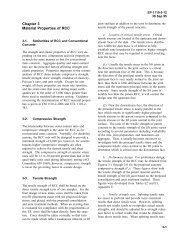
product. The three-dimensional graphite lattice pore structure <strong>of</strong> a typical activated carbon<br />
particle is shown in Figure 2-1.<br />
(2) Powdered Activated Carbon (PAC). PAC is made up <strong>of</strong> crushed or ground carbon<br />
particles, 95–100% <strong>of</strong> which will pass through a designated mesh sieve or sieves. The American<br />
Water Works Association Standard (AWWA, 1997) defines <strong>GAC</strong> as being retained on a 50mesh<br />
sieve (0.297 mm) and PAC material as finer material, while American Society for Testing<br />
and Materials (ASTM D5158) classifies particle sizes corresponding to an 80-mesh sieve (0.177<br />
mm) and smaller as PAC. PAC is not commonly used in a dedicated vessel, owing to the high<br />
headloss that would occur. PAC is generally added directly to other process units, such as raw<br />
water intakes, rapid mix basins, clarifiers, and gravity filters.<br />
(3) Granular Activated Carbon (<strong>GAC</strong>). <strong>GAC</strong> can be either in the granular form or extruded.<br />
<strong>GAC</strong> is designated by sizes such as 8 × 20, 20 × 40, or 8 × 30 for liquid phase applications<br />
and 4 × 6, 4 × 8 or 4 × 10 for vapor phase applications. A 20 × 40 carbon is made <strong>of</strong> particles<br />
that will pass through a U.S. Standard Mesh Size No. 20 sieve (0.84 mm) (generally specified<br />
as >85% passing) but be retained on a U.S. Standard Mesh Size No. 40 sieve (0.42 mm)<br />
(generally specified as >95% retained). AWWA (1992) B604 uses the 50-mesh sieve (0.297<br />
mm) as the minimum <strong>GAC</strong> size. The most popular aqueous phase carbons are the 12 × 40 and 8<br />
× 30 sizes because they have a good balance <strong>of</strong> size, surface area, and headloss characteristics.
DG 1110-1-2<br />
1 Mar 2001<br />
Figure 2-1. Activated carbon structure.<br />
2-2
2-3<br />
DG 1110-1-2<br />
1 Mar 2001<br />
The 12 × 40 carbon is normally recommended for drinking water applications where the water<br />
contains a low suspended solid content. The 8 × 30 size is the most commonly used for most<br />
applications (Appendix D, Carbonair).<br />
b. Non-carbon. Many alternative adsorption media are in general service today for removing<br />
organic constituents from vapor and liquid streams. Organically modified clays, polymeric adsorbents,<br />
and zeolite molecular sieves are the primary non-activated-carbon adsorbents currently<br />
used in hazardous waste treatment (Black & Veatch, 1998). See paragraph 3-3 for additional<br />
information.<br />
2-2. Properties <strong>of</strong> Granular Activated Carbon. Granular activated carbon properties are<br />
defined in ASTM D2652. In addition to these properties, the following paragraphs provide additional<br />
information.<br />
a. Particle Size Distribution. A standard test procedure for particle size distribution (PSD) is<br />
defined in ASTM D2862. Information derived from this test is used to specify the carbon particle<br />
size uniformity. Two particle size criteria are the effective size, which corresponds to the<br />
sieve size through which 10% <strong>of</strong> the material will pass, and the uniformity coefficient, which is<br />
the ratio <strong>of</strong> the sieve size that will just pass 60% <strong>of</strong> the material to the effective size. Generally,<br />
the rate <strong>of</strong> adsorption will increase as the particle size decreases, as the process step <strong>of</strong> diffusion<br />
to the carbon surface should be enhanced by the smaller particles. Note that another critical aspect<br />
<strong>of</strong> rate <strong>of</strong> adsorption is the pore size distribution, and development <strong>of</strong> “transport pores”<br />
within the particle that allow effective migration <strong>of</strong> contaminants to the point <strong>of</strong> adsorption.<br />
However, particle size may not be that important in all cases, as the porous nature <strong>of</strong> the carbon<br />
particles results in large surface areas in all sizes <strong>of</strong> carbon particles. Headloss through a carbon<br />
bed increases as the carbon particle size decreases and as the uniformity coefficient increases.<br />
b. Surface Area. Surface area is the carbon particle area available for adsorption. In general,<br />
the larger the surface area is, the greater is the adsorption capacity; however, this surface area<br />
needs to be effective. And a high degree <strong>of</strong> the area needs to be in the “adsorption pore” region,<br />
as well as being accessible to the contaminant with an effective “transport pore” structure, for the<br />
capacity to be useful. This is measured by determining the amount <strong>of</strong> nitrogen adsorbed by the<br />
carbon and reported as square meters per gram (commonly between 500 and 2000 m 2 /g). ASTM<br />
D 3037 identifies the procedure for determining the surface area using the nitrogen BET (Brunauer,<br />
Emmett, and Teller) method. Nitrogen is used because <strong>of</strong> its small size, which allows it to<br />
access the micropores within the carbon particle.<br />
c. Pore Volume. The pore volume is a measure <strong>of</strong> the total pore volume within the carbon<br />
particles in cubic centimeters per gram (cm 3 /g).<br />
d. Iodine Number. The iodine number refers to the milligrams <strong>of</strong> a 0.02 normal iodine solution<br />
adsorbed during a standard test (ASTM D4607). The iodine number is a measure <strong>of</strong> the
DG 1110-1-2<br />
1 Mar 2001<br />
volume present in pores from 10 to 28 Å (10 –10 m) in diameter. Carbons with a high percentage<br />
<strong>of</strong> pore sizes in this range would be suitable for adsorbing lower molecular weight substances<br />
from water. Carbons with a high iodine number are the most suitable for use as vapor phase carbons,<br />
as water molecules tend to effectively block <strong>of</strong>f and isolate pore sizes less than 28 Å. This<br />
restricts mass transfer in the micropores, resulting in poor carbon utilization and excessive cost.<br />
Virgin liquid phase carbons generally have an iodine number <strong>of</strong> 1000. Reactivated liquid phase<br />
carbon has an iodine number between 800 and 900.<br />
e. Molasses Number. The molasses number refers to the milligrams <strong>of</strong> molasses adsorbed<br />
during the standard test. The molasses number is a measure <strong>of</strong> the volume in pores greater than<br />
28 Å in diameter. A carbon with a high percentage <strong>of</strong> this size pore is suitable for adsorbing<br />
high molecular weight substances such as color bodies or other colloids. Carbons with a high<br />
molasses number are generally used for decolorizing process liquids. As such, the molasses<br />
number specification is generally only used in color removal applications, and is not a valid<br />
specification requirement for water treatment. This is a proprietary test, and should not be used<br />
in specifying <strong>GAC</strong>.<br />
f. Abrasion Number. The abrasion number measures the ability <strong>of</strong> carbon to withstand handling<br />
and slurry transfer. Two different tests are used, based on the type <strong>of</strong> carbon material. A<br />
Ro Tap abrasion test is used for bituminous-coal-based <strong>GAC</strong>, and a stirring abrasion test is used<br />
for the s<strong>of</strong>ter, lignite-coal-based <strong>GAC</strong>. The abrasion number is the ratio <strong>of</strong> the final average<br />
(mean) particle diameter to the original mean particle diameter (determined by sieve analyses)<br />
times 100. The desired average particle size <strong>of</strong> the <strong>GAC</strong> retained should be greater than or equal<br />
to 70%. This is <strong>of</strong> limited value because measuring techniques are not reproducible. Procedures<br />
are given in AWWA (1997) B604.<br />
g. Apparent Density. The apparent density is equal to the mass (weight) <strong>of</strong> a quantity <strong>of</strong> carbon<br />
divided by the volume it occupies (including pore volume and interparticle voids, adjusted<br />
for the moisture content). Generally, bituminous-based <strong>GAC</strong> has a density between 28–40<br />
pounds per cubic foot (pcf), lignite-based <strong>GAC</strong> has a density <strong>of</strong> approximately 22–26 pcf, and<br />
wood-based <strong>GAC</strong> has a density <strong>of</strong> 15–19 pcf (AWWA, 1997).<br />
h. Bulk Density. The bulk density is the unit weight <strong>of</strong> the carbon within the adsorber. Generally,<br />
the bulk density <strong>of</strong> liquid phase applications is 80–95% <strong>of</strong> the apparent density and, for<br />
vapor phase applications, it is 80–100% <strong>of</strong> the apparent density. Apparent density is used to determine<br />
the volumetric carbon usage rate since the carbon usage rate is typically stated in<br />
⎛ ⎞<br />
⎜ ⎟<br />
⎝ ⎠<br />
mg mg contaminant removed<br />
g gram <strong>of</strong> carbon<br />
.<br />
2-4
2-5<br />
DG 1110-1-2<br />
1 Mar 2001<br />
2-3. Isotherms. An isotherm is the relationship that shows the distribution <strong>of</strong> adsorbate<br />
(material adsorbed) between the adsorbed phase (that adsorbed on the surface <strong>of</strong> the adsorbent)<br />
and the solution phase at equilibrium. Media manufacturers are a source <strong>of</strong> adsorption isotherms.<br />
Many manufacturers are continuing to conduct research on their products and can <strong>of</strong>ten<br />
supply chemical-specific adsorption isotherms for their products. However, many <strong>of</strong> these company<br />
isotherms are batch isotherms used as pro<strong>of</strong> <strong>of</strong> concept data (i.e., to show that a particular<br />
product can adsorb a particular chemical). Actual working adsorption capacity may be much<br />
less than equilibrium batch capacity because other constituents may be present in water, such as<br />
total organic carbon, and because <strong>of</strong> the non-instantaneous adsorption kinetics. So, you should<br />
carefully check manufacturer’s data and use them with caution when designing an adsorption<br />
system. The designer should also ask the manufacturer for contacts at installations using the media,<br />
so that scale-up factors and common operational problems can be investigated.<br />
a. <strong>GAC</strong> Isotherms. There are three generally recognized mathematical relationships that were<br />
developed to describe the equilibrium distribution <strong>of</strong> a solute between the dissolved (liquid) and<br />
adsorbed (solid) phases. These relationships help interpret the adsorption data obtained during<br />
constant temperature tests, referred to as adsorption isotherms.<br />
• The Langmuir isotherm equation assumes that fixed individual sites exist on the surface<br />
<strong>of</strong> the adsorbent, each <strong>of</strong> these sites being capable <strong>of</strong> adsorbing one molecule, resulting in<br />
a layer one molecule thick over the entire carbon surface. The Langmuir model also assumes<br />
that all sites adsorb the adsorbate equally.<br />
• The Brunauer, Emmett, and Teller (BET) equation also assumes the adsorbent surface is<br />
composed <strong>of</strong> fixed individual sites. However, the BET equation assumes that molecules<br />
can be adsorbed more than one layer thick on the surface <strong>of</strong> the adsorbent. The BET<br />
equation assumes that the energy required to adsorb the first particle layer is adequate to<br />
hold the monolayer in place.<br />
• The Fruendlich isotherm equation assumes that the adsorbent has a heterogeneous surface<br />
composed <strong>of</strong> adsorption sites with different adsorption potentials. This equation assumes<br />
that each class <strong>of</strong> adsorption site adsorbs molecules, as in the Langmuir Equation. The<br />
Fruendlich Isotherm Equation is the most widely used and will be discussed further.<br />
x<br />
KC<br />
m =<br />
1<br />
n<br />
where<br />
x = amount <strong>of</strong> solute adsorbed (µg, mg, or g)<br />
m = mass <strong>of</strong> adsorbent (mg or g)<br />
C = concentration <strong>of</strong> solute remaining in solution after adsorption is complete (at equilibrium)<br />
(mg/L)
DG 1110-1-2<br />
1 Mar 2001<br />
K, n = constants that must be determined for each solute, carbon type, and temperature.<br />
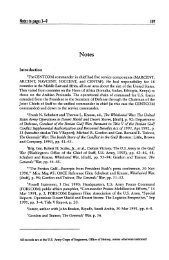
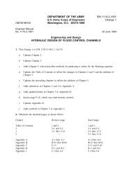
(1) An example <strong>of</strong> an isotherm for TCE is presented in Figure 2-2. K and 1/n or n values<br />
for multiple contaminant mixtures should be determined by laboratory tests.<br />
(2) Single component isotherms may be used for an order-<strong>of</strong>-magnitude carbon usage estimate<br />
or for determining the feasibility <strong>of</strong> <strong>GAC</strong> adsorption using suppliers’ literature or previously<br />
published literature (Dobbs and Cohen, 1980) for individual compounds. Another source<br />
<strong>of</strong> liquid phase isotherm data constants is the EPA Treatability Database maintained by the National<br />
Risk Management Research Laboratory (NRMRL), formerly known as the Risk Reduction<br />
Engineering Lab (RREL) (http://www.epa.gov/tdbnrmrl). Vapor phase isotherms are not readily<br />
available in the literature.<br />
(3) Some general rules <strong>of</strong> thumb, uses, and caveats that are helpful in isotherm interpretation<br />
are as follows:<br />
• A flat isotherm curve indicates a narrow Mass Transfer Zone (MTZ), meaning that the<br />
<strong>GAC</strong> generally adsorbs contaminants at a constant capacity over a relatively wide range<br />
<strong>of</strong> equilibrium concentrations. Given an adequate capacity, carbons exhibiting this type<br />
<strong>of</strong> isotherm will be very cost effective, and adsorption system design will be simplified<br />
owing to a shorter mass transfer zone (see Figure 2-2).<br />
• A steep isotherm curve indicates a wide MTZ, with the adsorption capacity increasing as<br />
equilibrium concentration increases. Carbons exhibiting this type <strong>of</strong> isotherm curve tend<br />
to be more cost effective.<br />
• A change in isotherm slope generally occurs for wastes that contain several compounds<br />
with variable adsorption capacities. An inflection point occurs when one compound is<br />
preferentially adsorbed over another and desorption occurs, so that the preferentially adsorbed<br />
compound can utilize sites previously used by less adsorbable compounds (see<br />
Figure 2-3).<br />
(4) Isotherms can be developed from data obtained in the laboratory and from existing data<br />
sources, such as the National Risk Management Research Laboratory (NRMRL) Treatability<br />
Database, texts, and suppliers’ literature. A typical example <strong>of</strong> TCE isotherm data, which was<br />
obtained from the NRMRL database, is provided in Figure 2-2. A procedure for calculating an<br />
isotherm is included in Appendix C.<br />
b. Polymeric, Clay, Zeolite Molecular Sieve Isotherms. Isotherms for these media are developed<br />
in the same way as for carbon media. However, most <strong>of</strong> the isotherm data for non-carbon<br />
adsorption media must be obtained from the manufacturer or from laboratory tests.<br />
2-6
2-7<br />
DG 1110-1-2<br />
1 Mar 2001<br />
2-4. Isotherm Testing. Isotherms are discussed in Paragraph 2-3, and the process for developing<br />
an isotherm is addressed in Appendix C. Although the example in Appendix C is specifically<br />
developed for a liquid phase application, the vapor phase method is similar. The following<br />
paragraphs highlight the types <strong>of</strong> information that can be obtained from isotherm testing versus<br />
column testing. Isotherms are static, equilibrium tests for a given set <strong>of</strong> conditions. Ideally,<br />
isotherms should not be used for the final design <strong>of</strong> a liquid phase system. Procedures for laboratory<br />
development <strong>of</strong> an isotherm are presented in a variety <strong>of</strong> texts (Benefield, 1982) or as<br />
specified in ASTM D 3860.<br />
a. Although not advisable for liquid phase applications, published adsorption isotherm data<br />
are <strong>of</strong>ten used to design vapor phase adsorption systems without bench and pilot testing. For the<br />
same contaminant, vapor phase carbon usually has a higher adsorptive capacity than liquid phase<br />
carbon, because less adsorptive sites will be taken up by water and humidity. At a 100% relative<br />
humidity, the vapor phase carbon's adsorptive capacity will approach the liquid phase carbon adsorptive<br />
capacity (Appendix D, Carbonair). However, you should remember that most published<br />
isotherm data represent only a single contaminant in a pure medium, and mixed contaminants<br />
may behave differently (see Tables 2-1 and 2-2).<br />
b. One source <strong>of</strong> published isotherms is the Adsorption Equilibrium Data Handbook<br />
(Valenzuela and Meyers, 1989). This handbook contains many gas/liquid isotherms. While<br />
most <strong>of</strong> the isotherms are for activated carbon, there are some for carbon molecular sieves, silica<br />
gel, and zeolites. A source <strong>of</strong> information on the Fruendlich isotherm equation is the Carbon<br />
Adsorption Isotherms for Toxic Organics (Dobbs and Cohen, 1980). This particular source used<br />
only a 2-hour test period in lieu <strong>of</strong> the 24-hour period currently used by industry today. Liquid<br />
phase and vapor phase applications are different because the mass transfer characteristics <strong>of</strong> the<br />
two phases are different. The mass transfer kinetics <strong>of</strong> a contaminant from the vapor phase to the<br />
solid phase is nearly instantaneous, while the mass transfer kinetics from the bulk liquid phase to<br />
the solid phase is influenced by the presence <strong>of</strong> the solute, and may be the rate limiting step in<br />
some instances. There are four phases to the liquid phase adsorption process. The contaminant<br />
must first travel from the bulk liquid phase to the liquid film surrounding the carbon particle.<br />
Second, the contaminant must travel through the liquid film surrounding the carbon to the interstitial<br />
voids. Third, the contaminant must diffuse through the carbon voids in the carbon solid<br />
phase, and fourth, finally adsorb onto the carbon. A more comprehensive discussion <strong>of</strong> the<br />
kinetics <strong>of</strong> adsorption can be obtained from texts (Faust and Aly, 1987).
DG 1110-1-2<br />
1 Mar 2001<br />
RREL Treatability Database Ver No. 4.0<br />
TRICHLOROETHYLENE<br />
CAS NO: 79-01-6<br />
COMPOUND TYPE: HYDROCARBON, HALOGENATED<br />
FORMULA: C2 H Cl3<br />
CHEMICAL AND PHYSICAL PROPERTIES:<br />
MOLECULAR WEIGHT: 131.39<br />
MELTING POINT (C): -84.8<br />
BOILING POINT (C): 86.7<br />
VAPOR PRESSURE @ T (C), TORR: 77 @ 25<br />
SOLUBILITY IN WATER @ T (C), MG/L: 1100 @ 25<br />
LOG OCTANOL/WATER PARTITION COEFFICIENT: 2.53<br />
HENRY’S LAW CONSTANT, ATM x M3 MOLE-1: 1.17 E-2 @ 25<br />
x/m (ug/gr)<br />
100000<br />
10000<br />
1000<br />
100<br />
TCE Isotherm<br />
10<br />
1 10 100 1000<br />
Concentration (ug/L)<br />
ENVIRONMENTAL DATA<br />
-----------------------------------<br />
REFERENCE DATABASE<br />
FREUNDLICH ISOTHERM DATA<br />
--------------------------------------------<br />
ADSORBENT MATRIX K 1/N Ce UNITS X/M UNITS<br />
FILTRASORB 400 C 3390 0.146 µg/L µg/g<br />
WESTVACO WV-G C 3260 0.407 µg/L µg/g<br />
WESTVACO WV-W C 1060 0.500 µg/L µg/g<br />
HYDRODARCO 3000 C 713 0.470 µg/L µg/g<br />
FILTRASORB 300 C 28 0.62 mg/L mg/g<br />
FILTRASORB 400 C 36.3 0.592 mg/L mg/g<br />
FILTRASORB 400 C 45 0.625 mg/L mg/g<br />
FILTRASORB 400 C 2 0.482 µg/L µg/g<br />
Figure 2-2. Trichloroethylene data.<br />
2-8
x/m<br />
2-9<br />
Inflection Point<br />
Concentration, C e<br />
Figure 2-3. Variable capacity adsorption isotherm.<br />
c. Liquid phase isotherms are useful screening tools for determining the following:<br />
• If adsorption is a viable technology.<br />
DG 1110-1-2<br />
1 Mar 2001<br />
• The equilibrium capacity, or approximate capacity at breakthrough, so a preliminary estimate<br />
<strong>of</strong> carbon usage can be made.<br />
• The relative difficulty to remove individual contaminants if single-constituent isotherms<br />
are used, and the identity <strong>of</strong> the initial breakthrough compound.<br />
• Changes in equilibrium adsorption capacity relative to the concentration <strong>of</strong> contaminants<br />
in the waste stream, and the effects <strong>of</strong> changes in waste stream concentration.<br />
• The maximum amount <strong>of</strong> contaminant that can be adsorbed by <strong>GAC</strong> at a given<br />
concentration.<br />
• The relative efficiencies <strong>of</strong> different types <strong>of</strong> carbons to identify which should be used for<br />
dynamic testing.<br />
d. Liquid phase column testing will provide such data as contact time, bed depth, pre-treatment<br />
requirements, carbon dosage, headloss characteristics, and breakthrough curves. Column<br />
testing will also identify how contaminants that are not <strong>of</strong> regulatory concern, such as iron or<br />
color containing compounds, will affect the efficiency <strong>of</strong> the treatment process.
DG 1110-1-2<br />
1 Mar 2001<br />
Table 2-1<br />
Freundlich adsorption isotherm constants for toxic organic chemicals (mean adsorption<br />
capacity [mg/g] at equilibrium concentration <strong>of</strong> 500 µg/L)<br />
Difficult to Adsorb<br />
Compounds<br />
0.4*<br />
0.4*<br />
0.5*<br />
Methylene Chloride<br />
Trans 1, 2 -Dichloroethylene<br />
1, 2 - Dichloroethane<br />
1.0 10 100<br />
Freundlich<br />
Parameters<br />
K l/n<br />
Benzene 1.0 1.6*<br />
16.6 0.4**<br />
49.3 0.6†<br />
29.5 0.4††<br />
14.2 0.4§<br />
Carbon Tetrachloride 11.1 0.8*<br />
28.5 0.8†<br />
38.1 0.7**<br />
25.8 0.7††<br />
14.2 0.7§<br />
14.8 0.4§§<br />
Chlorobenzene 91.0 1.0*<br />
1,2-dichlorobenzene 129.0<br />
1,3-dichlorobenzene 118.0<br />
1,4-dichlorobenzene 121.0<br />
226.0 0.4**<br />
1,2-dichloroethene 3.6 0.8*<br />
5.7 0.5§§<br />
cis-1,2-dichloroethylene 6.5 0.7†<br />
8.4 0.5§§<br />
Benzene<br />
Carbon Tetrachloride<br />
Cis 1,2 - Dichloroethylene<br />
1,1,1 - Trichloroethane<br />
1,1 - Dichloroethylene<br />
2-10<br />
Trichloroethylene<br />
Chlorobenzene<br />
1,2,4- Trichlorbenzene<br />
1,4 - Dichlorobenzene<br />
1,2 - Dichlorobenzene<br />
1,3 - Dichlorobenzene<br />
Tetrachloroethylene<br />
K l/n<br />
trans-1,2-dichloroethylene 3.1 0.5*<br />
1,1-dichloroethylene 4.9 0.5*<br />
Methylene chloride 1.3 1.2*<br />
1.6 0.7***<br />
Tetrachloroethylene 50.8 0.6*<br />
84.1 0.4§§<br />
273.0 0.6***<br />
1,2,4-trichlorobenzene 157.0 0.3*<br />
1,1,1-trichloroethane 2.5 0.3*<br />
9.4 0.5§§<br />
Trichloroethylene 28.0 0.6*<br />
26.2 0.5‡<br />
28.2 0.4§§<br />
Vinyl chloride Not Reported<br />
Freundlich equation:<br />
x/m(mg/gm) = K C (mg/1/n)<br />
Freundlich<br />
Parameters<br />
* Filtrasorb ® 300 § Hydrodarco ® 1030 † Norit<br />
** Filtrasorb ® 400 §§ Witcarb ® 950 †† Nuchar ® WV-G<br />
*** Filtrasorb ® 400 ‡ Filtrasorb ® 300<br />
Easily Adsorbed<br />
Compounds
2-11<br />
DG 1110-1-2<br />
1 Mar 2001<br />
Table 2-2<br />
Freundlich adsorption Isotherm constants for toxic organic compounds† (Dobbs<br />
and Cohen 1980)<br />
Compound K(mg/g)(L/mg) 1/n l/n<br />
PCB 14,100 1.03<br />
Bis(2-ethylhexyl phthalate 11,300 1.5<br />
Heptachlor 9,320 0.92<br />
Heptachlor epoxide 2,120 0.75<br />
Butylbenzyl phthalate 1,520 1.26<br />
Toxaphene 950 0.74<br />
Endosulfan sulfate 686 0.81<br />
Endrin 666 0.80<br />
Fluoranthene 664 0.61<br />
Aldrin 651 0.92<br />
PCB-1232 630 0.73<br />
∃ - Endosulfan 615 0.83<br />
Dieldrin 606 0.51<br />
Alachlor 479 0.26<br />
Hexachlorobenzene 450 0.60<br />
Pentachlorophenol 436 0.34<br />
Anthracene 376 0.70<br />
4 – Nitrobiphenyl 370 0.27<br />
Fluorene 330 0.28<br />
Styrene 327 0.48<br />
DDT 322 0.50<br />
2 – Acetylamin<strong>of</strong>luorene 318 0.12<br />
∀ - BHC 303 0.43<br />
Anethole 300 0.42<br />
3,3 – Dichlorobenzidine 300 0.20<br />
( - BHC (lindane) 285 0.43<br />
2 – Chloronaphthalene 280 0.46<br />
Phenylmercuric acetate 270 0.44<br />
Carb<strong>of</strong>uran 266 0.41<br />
1,2 – Dichlorobenzene 263 0.38<br />
Hexachlorobutadiene 258 0.45<br />
∆ - Nonylphenol 250 0.37<br />
4-Dimethylaminoazobenzene 249 0.24<br />
PCB – 1221 242 0.70<br />
DDE 232 0.37<br />
m-Xylene 230 0.75<br />
Acridine yellow 230 0.12<br />
Dibromochloropropane (DBCP) 224 0.51<br />
Benzidine dihydrochloride 220 0.37<br />
∃ - BHC 220 0.49<br />
n-Butylphthalate 220 0.45<br />
n-Nitrosodiphenylamine 220 0.37<br />
Silvex 215 0.38<br />
Phenanthrene 215 0.44<br />
Dimethylphenylcarbinol 210 0.34<br />
4 – Aminobiphenyl 200 0.26
DG 1110-1-2<br />
1 Mar 2001<br />
Table 2 (continued)<br />
Compound K(mg/g)(L/mg) 1/n l/n<br />
∃ - Naphthol 200 0.26<br />
∆ - Xylene 200 0.42<br />
∀ - Endosulfan 194 0.50<br />
Chlordane 190 0.33<br />
Acenaphthene 190 0.36<br />
4,4’ Methylene-bis<br />
(2-chloroaniline)<br />
190 0.64<br />
Benzo[6]fluoranthene 181 0.57<br />
Acridine orange 180 0.29<br />
∀-Naphthol 180 0.32<br />
Ethylbenzene 175 0.53<br />
≅-Xylene 174 0.47<br />
4,6-Dinitro-≅-cresol 169 0.27<br />
∀-Naphthylamine 160 0.34<br />
2,4-Dichlorophenol 157 0.15<br />
1,2,4-Trichlorobenzene 157 0.31<br />
2,4,6-Trichlorophenol 155 0.40<br />
∃-Naphthylamine 150 0.30<br />
2,4-Dinitrotoluene 146 0.31<br />
2,6-Dinitrotoluene 145 0.32<br />
4-Bromophenyl phenyl ether 144 0.68<br />
∆-Nitroaniline 140 0.27<br />
1,1-Diphenylhydrazine 135 0.16<br />
Naphthalene 132 0.42<br />
Aldicarb 132 0.40<br />
1-Chloro-2-nitrobenzene 130 0.46<br />
p-Chlorometacresol 124 0.16<br />
1,4-Dichlorobenzene 121 0.47<br />
Benzothiazole 120 0.27<br />
Diphenylamine 120 0.31<br />
Guanine 120 0.40<br />
1,3-Dichlorobenzene 118 0.45<br />
Acenaphthylene 115 0.37<br />
Methoxychlor 115 0.36<br />
4-Chlorophenyl phenyl ether 111 0.26<br />
Diethyl phthalate 110 0.27<br />
Chlorobenzene 100 0.35<br />
Toluene 100 0.45<br />
2-Nitrophenol 99 0.34<br />
Dimethyl phthalate 97 0.41<br />
Hexachloroethane 97 0.38<br />
2,4-Dimethylphenol 78 0.44<br />
4-Nitrophenol 76 0.25<br />
Acetophenone 74 0.44<br />
1,2,3,4-Tetrahydronaphthalene 74 0.81<br />
Adenine 71 0.38<br />
Dibenzo[∀h]anthracene 69 0.75<br />
Nitrobenzene 68 0.43<br />
2,4-D 67 0.27<br />
2-12
Table 2 (continued)<br />
2-13<br />
DG 1110-1-2<br />
1 Mar 2001<br />
Compound K(mg/g)(L/mg) 1/n l/n<br />
3,4-Benz<strong>of</strong>luoranthene 57 0.37<br />
2-Chlorophenol 51 0.41<br />
Tetrachloroethylene 51 0.56<br />
≅-Anisidine 50 0.34<br />
5-Bromouracil 44 0.47<br />
Benzo[∀]pyrene 34 0.44<br />
2,4-Dinitrophenol 33 0.61<br />
Isophorone 32 0.39<br />
Trichloroethylene 28 0.62<br />
Thymine 27 0.51<br />
5-Chlorouracil 25 0.58<br />
N-Nitrosodi-n-propylamine 24 0.26<br />
Bis(2-Chloroisopropyl)ether 24 0.57<br />
1,2-Dibromoethene (EDB) 22 0.46<br />
Phenol 21 0.54<br />
Brom<strong>of</strong>orm 20 0.52<br />
1,2-Dichloropropane 19 0.59<br />
1,2-trans-Dichloroethylene 14 0.45<br />
cis-1,2-Dichloroethylene 12 0.59<br />
Carbon tetrachloride 11 0.83<br />
Bis(2-Chloroethyoxy)methane 11 0.65<br />
Uracil 11 0.63<br />
Benzo[g,h,i]perylene 11 0.37<br />
1,1,2,2-Tetrachloroethane 11 0.37<br />
1,2-Dichloropropene 8.2 0.46<br />
Dichlorobromomethane 7.9 0.61<br />
Cyclohezanone 6.2 0.75<br />
1,1,2-Trichloroethane 5.8 0.60<br />
Trichlor<strong>of</strong>luoromethane 5.6 0.24<br />
5-Fluorouracil 5.5 1.0<br />
1,1-Dichloroethylene 4.9 0.54<br />
Dibromochloromethane 4.8 0.34<br />
2-Chloroethyl vinyl ether 3.9 0.80<br />
1,2-Dichloroethane 3.6 0.83<br />
Chlor<strong>of</strong>orm 2.6 0.73<br />
1,1,1-Trichloroethane 2.5 0.34<br />
1,1-Dichloroethane 1.8 0.53<br />
Acrylonitrile 1.4 0.51<br />
Methylene chloride 1.3 1.16<br />
Acrolein 1.2 0.65<br />
Cytosine 1.1 1.6<br />
Benzene 1.0 1.6<br />
Ethylenediaminetetraacetic acid 0.86 1.5<br />
Benzoic acid 0.76 1.8<br />
Chloroethane 0.59 0.95<br />
N-Dimethylnitrosamine 6.8 x 10 -5 6.6<br />
The isotherms are for the compounds in distilled water, with different activated carbons. The values <strong>of</strong> K and 1/n<br />
should be used only as rough estimates <strong>of</strong> the values that will be obtained using other types <strong>of</strong> water and other activated<br />
carbon.
DG 1110-1-2<br />
1 Mar 2001<br />
2-5. Dynamic Operation Testing. The following parameters must be considered when<br />
designing a pilot scale evaluation.<br />
a. Breakthrough Curves. The breakthrough curve can be defined as the “S” shaped curve<br />
that typically results when the effluent adsorbate concentration is plotted against time or volume.<br />
Breakthrough curves can be constructed for full scale, dynamic, or pilot testing. The breakthrough<br />
point is the point on the breakthrough curve where the effluent adsorbate concentration<br />
reaches its maximum allowable concentration, which <strong>of</strong>ten corresponds to the treatment goal.<br />
The treatment goal is usually based on regulatory or risk based numbers (see Figure 2-4).<br />
b. Mass Transfer Zone. The mass transfer zone (MTZ) is the area within the adsorbate bed<br />
where adsorbate is actually being adsorbed on the adsorbent. The MTZ typically moves from the<br />
influent end toward the effluent end <strong>of</strong> the adsorbent bed during operation. That is, as the<br />
adsorbent near the influent becomes saturated (spent) with adsorbate, the zone <strong>of</strong> active adsorption<br />
moves toward the effluent end <strong>of</strong> the bed where the adsorbate is not yet saturated. The MTZ<br />
is sometimes called the adsorption zone or critical bed depth. The MTZ is generally a band,<br />
between the spent carbon and the fresh carbon, where adsorbate is removed and the dissolved<br />
adsorbate concentration ranges from CO to Ce.<br />
(1) The length <strong>of</strong> the MTZ can be defined as LMTZ. When LMTZ = bed depth, it becomes<br />
LCRIT, or the theoretical minimum bed depth necessary to obtain the desired removal.<br />
(2) As adsorption capacity is used up in the initial MTZ, the MTZ advances down the bed<br />
until the adsorbate begins to appear in the effluent. The concentration gradually increases until it<br />
equals the influent concentration. In cases where there are some very strongly adsorbed components,<br />
in addition to a mixture <strong>of</strong> less strongly adsorbed components, the effluent concentration<br />
very seldom reaches the influent concentration because only the components with the faster rate<br />
<strong>of</strong> movement through the adsorber are in the breakthrough curve. The MTZ is illustrated in Figure<br />
2-5.<br />
(3) Adsorption capacity is influenced by many factors, such as flow rate, temperature, and<br />
pH (liquid phase). The adsorption column may be considered exhausted when the effluent adsorbate<br />
concentration equals 95–100% <strong>of</strong> the influent concentration. This is illustrated in Figure<br />
2-5.<br />
2-14
VAPOR ADSORPTION<br />
Maximum Allowable Effluent<br />
Concentration<br />
(C e )<br />
Maximum Adsorption Capacity 90-100% (C o )<br />
Breakthrough<br />
VOLUME OF AIR/WATER TREATED<br />
2-15<br />
LIQUID ADSORPTION<br />
C o = Influent Concentration<br />
C e - Effluent Concentration<br />
Figure 2-4. Comparison <strong>of</strong> idealized vapor and liquid breakthrough curves.<br />
DG 1110-1-2<br />
1 Mar 2001<br />
EFFLUENT CONCENTRATION
DG 1110-1-2<br />
1 Mar 2001<br />
EFFLUENT CONCENTRATION<br />
Used<br />
Carbon<br />
MTZ<br />
Clean<br />
Media<br />
VOLUME TREATED<br />
Figure 2-5. Adsorption column mass transfer zone and idealized breakthrough zone.<br />
2-16
2-17<br />
DG 1110-1-2<br />
1 Mar 2001<br />
2-6. Pilot Tests. Pilot studies are almost always recommended for liquid phase applications.<br />
After bench scale isotherm tests have provided "pro<strong>of</strong> <strong>of</strong> concept" data for the media (e.g. <strong>GAC</strong>),<br />
pilot testing should be used to determine if the site-specific conditions will interfere with the media<br />
and to test solutions for managing the interferences. Pilot tests will verify the characteristics<br />
<strong>of</strong> the breakthrough curve at selected process parameters, such as surface loading rates and<br />
empty bed contact times. For example, there may be competition for adsorption sites among different<br />
compounds in the waste stream. Analysis for these competing compounds may not be<br />
routinely conducted, so their presence and concentration in the waste stream would not be<br />
known. This type <strong>of</strong> competition can be minimized by selecting a product that selectively adsorbs<br />
only the compounds <strong>of</strong> concern. Also, variations in the water chemistry (pH, buffer<br />
capacity, etc.) may affect the performance and capacity <strong>of</strong> the adsorbent. Pilot tests should also<br />
be used to generate scale up factors for the full-scale design.<br />
a. Several manufacturers have mobile pilot systems, and most manufacturers will (for a fee)<br />
conduct pilot testing <strong>of</strong> waste streams for customers. It may be possible to negotiate package<br />
deals, where testing costs would be reduced if the pilot scale manufacturer were selected for the<br />
full-scale project.<br />
b. There are two basic types <strong>of</strong> column tests that can be run to determine the parameters<br />
mentioned above: the standard pilot column test, and the high pressure minicolumn test. The<br />
standard pilot column test consists <strong>of</strong> four or more carbon columns in series. The columns are 50<br />
to 150 mm (2 to 6 in.) in diameter, generally contain 1.8 to 3.6 m (2 to 4 ft) <strong>of</strong> <strong>GAC</strong>, and operate<br />
in either the downflow or upflow mode. If suspended solids are a concern for the full scale<br />
operation, downflow operation with backwashing capabilities to remove filtered solids is generally<br />
the best option. In an upflow mode, the solids would likely plug most distributors. The upflow<br />
operation typically generates carbon fines and, thus, gray water. Downflow mode is generally<br />
preferred for liquid streams, unless they are susceptible to biological fouling. Four pilot columns<br />
are generally selected to ensure that the wave front or mass transfer zone can be tracked<br />
through the columns. The column operating characteristics (e.g., surface loading rate, detention<br />
time, vertical velocity through the bed) should be similar to those expected in the full scale system.<br />
Typically, in full-scale water-treatment applications, except large potable water plants that<br />
have adsorbers operating in parallel, the mass transfer zone is contained in the first adsorber in a<br />
system having two adsorbers in series. In unique process applications, where the contact time is<br />
several hours, three beds in series may be necessary. There are very few systems with four<br />
vessels in series. Methods to apply the data to other conditions, such as the bed depth service<br />
time (BDST), and Bohart Adams relationships and operating line method are described in various<br />
references (Benefield, 1982; Faust and Aly, 1987; AWWA, 1997; Erskine and Schuliger,<br />
1971) A typical pilot column configuration is shown in Figure 2-6.
DG 1110-1-2<br />
1 Mar 2001<br />
c. A high pressure water minicolumn (HPMC) test or small scale column test was developed<br />
to reduce the length <strong>of</strong> time required to obtain operational data from a column test (see Figure 2-<br />
6). A traditional column test could take a month or more to run, while a HPMC test can be completed<br />
in a matter <strong>of</strong> hours. The HPMC process used is generally manufacturer-specific but depends<br />
largely upon mathematical modeling, given the particle size used in the HPMC and test<br />
parameters and database <strong>of</strong> past tests, as well as the experience <strong>of</strong> the individual interpreting the<br />
test data. The apparatus consists <strong>of</strong> a 0.4- to 2.0-mm-diameter column with a bed depth ranging<br />
from 10 to 100 mm. It uses a sample <strong>of</strong> the subject test <strong>GAC</strong>, crushed to pass a 60 × 80 mesh or<br />
smaller. The minicolumn tests are generally about one order <strong>of</strong> magnitude less expensive, can be<br />
completed quickly, require a smaller volume <strong>of</strong> water, have minimal chance for biological or<br />
other deterioration <strong>of</strong> the sample, and multiple carbons can easily be tested to obtain the most<br />
effective design. Additional information can be obtained from testing labs, carbon manufacturers,<br />
and AWWA Water Quality and Treatment (1997). A typical apparatus is shown in Figure 2-<br />
7. A procedure for estimating <strong>GAC</strong> performance using a slightly larger diameter column <strong>of</strong> 25.4<br />
mm + 0.1 mm is identified in ASTM D3922.<br />
2-7. Spent Carbon Management. Spent carbon has the potential to be regulated for<br />
disposal under the Resource Conservation and Recovery Act (RCRA). Spent carbon used to treat<br />
listed hazardous waste or which exhibits a RCRA hazardous characteristic (ignitable, corrosive,<br />
reactive, or exceeding toxicity characteristic leaching procedure threshold levels) must be<br />
managed as a hazardous waste after use in an adsorption process and be manifested to a<br />
permitted RCRA Treatment, Storage or Disposal Facility (TSDF). This TSDF may be either a<br />
disposal or a regeneration facility. If it is managed on-site under CERCLA, a permit is not<br />
required, but substantive requirements applicable to TSDFs must be met. On the other hand, if it<br />
was not used to treat listed waste, and it does not exhibit a hazardous characteristic, then the<br />
spent carbon can be disposed <strong>of</strong> or regenerated without being subject to RCRA permitting or<br />
manifesting requirements. The determination <strong>of</strong> RCRA status is the legal responsibility <strong>of</strong> the<br />
generator (operator/owner) <strong>of</strong> the treatment facility. Coordinate with carbon manufacturers, or<br />
your local regulatory specialist, for additional information.<br />
2-8. Safety Concerns. The safety concerns unique to carbon adsorption are discussed in EM<br />
1110-1-4007.<br />
2-18
Influent<br />
Backwash<br />
Outlet (typ)<br />
Backwash<br />
Inlet (typ)<br />
Sample Port (typ)<br />
Alternate Feed to First Column<br />
Pressure Gage (typ)<br />
Figure 2-6. Typical pilot column apparatus.<br />
2-19<br />
Porous Plate,Glass Wool, or<br />
Stainless Steel Screen (typ)<br />
DG 1110-1-2<br />
1 Mar 2001<br />
Flow Rate<br />
Meter<br />
Effluent
DG 1110-1-2<br />
1 Mar 2001<br />
Figure 2-7. Minicolumn apparatus.<br />
2-20
CHAPTER 3<br />
APPLICATIONS AND LIMITATIONS<br />
3.1. Carbon Adsorption.<br />
a. Liquid Phase Carbon.<br />
3-1<br />
DG 1110-1-2<br />
1 Mar 2001<br />
(1) Applications. Some typical rules <strong>of</strong> thumb for types <strong>of</strong> compounds that are amenable<br />
to carbon adsorption are as follows:<br />
• Larger molecules adsorb better than smaller molecules.<br />
• Non-polar molecules adsorb better than polar molecules.<br />
• Non-soluble or slightly soluble molecules adsorb better than highly soluble molecules.<br />
• Based on the polarity or solubility, or both, <strong>of</strong> the molecule being adsorbed, pH may have<br />
an influence on the extent <strong>of</strong> adsorption.<br />
• Temperature increases the rate <strong>of</strong> diffusion through the liquid to the adsorption sites, but<br />
since the adsorption process is exothermic, increases in temperature may reduce the degree<br />
<strong>of</strong> adsorption. This temperature effect is negligible in water treatment applications<br />
and ambient vapor phase applications.<br />
(2) Chemicals Adsorbed. The following are examples:<br />
• Alcohols are poorly adsorbed, they are very soluble and highly polar.<br />
• Aldehydes are highly polar, and as molecular weight increases, the polarity decreases,<br />
and adsorbability increases.<br />
• Amines are similar in structure to ammonia (NH3) except the nitrogen is bonded to an organic<br />
group. Adsorption is limited by polarity and solubility.<br />
• Chlorinated armoatics, and chlorinated aliphatics are low-polarity and low-solubility<br />
compounds, which make them generally quite adsorbable.<br />
• Glycols are water-soluble and not very adsorbable.
DG 1110-1-2<br />
1 Mar 2001<br />
• Higher molecular weight organic compounds will generally be more adsorbable owing to<br />
adsorptive attraction relative to size.<br />
(3) Types <strong>of</strong> Carbon. Activated carbon is a generic term for a variety <strong>of</strong> products that consist<br />
primarily <strong>of</strong> elemental carbon. Numerous raw materials can be used to produce carbons,<br />
such as coal, wood, and pitch, and agricultural products such as cotton gin waste and coconut<br />
shells. Materials most commonly used for liquid phase <strong>GAC</strong> include both bituminous and lignite<br />
coal, and coconut shells.<br />
(a) Bituminous <strong>GAC</strong> is the one most frequently used for treating low concentrations <strong>of</strong><br />
low molecular weight organic contaminants in the aqueous phase. Bituminous coal will also<br />
have a more fully developed pore distribution, including “transport pores” that improve the rate<br />
<strong>of</strong> adsorption making it effective for water treatment. Bituminous <strong>GAC</strong> has a relatively large<br />
surface area, approximately 900 m 2 /g, and an apparent density <strong>of</strong> approximately 0.50 g/cm 3 (30<br />
lb/ft 3 ). These carbons are usually harder than other types except coconut, and, therefore, are<br />
more abrasion resistant, and can be more vigorously backwashed without damage.<br />
(b) Lignite <strong>GAC</strong> generally has less total surface area than bituminous <strong>GAC</strong>. It is a less<br />
dense, slightly s<strong>of</strong>ter coal, has a higher percentage <strong>of</strong> meso (transitional) macro pores, and is<br />
used more for larger molecules. Therefore, it is used more in decolorizing applications. Lignite<br />
<strong>GAC</strong> has a surface area <strong>of</strong> approximately 650 m 2 /g and an apparent density <strong>of</strong> approximately<br />
0.50 g/cm 3 (25 lb/ft 3 ).<br />
(c) Coconut-shell-based <strong>GAC</strong> generally has a larger surface area than coal-based <strong>GAC</strong>,<br />
and a very large percentage <strong>of</strong> micropores. Coconut-shell-based <strong>GAC</strong> has a surface area generally<br />
over 1000 m 2 /g and an apparent density <strong>of</strong> approximately 0.50 g/cm 3 (30 lb/ ft 3 ). Coconut<br />
shell based carbons may not have the more fully developed pore structure that coal-based carbons<br />
have, because their source is vegetative material. Consideration should be given to rate <strong>of</strong><br />
adsorption effects in liquid treatment. It is used primarily in vapor-phase applications. Coconutshell-based<br />
carbon is slightly more expensive to produce than coal-based <strong>GAC</strong>, since only about<br />
2% <strong>of</strong> the raw material is recoverable as <strong>GAC</strong>, versus 8–9% for coal-based carbons.<br />
(4) Isotherms. Isotherms are discussed in paragraph 2-3.<br />
(5) Pressure Drop. Headloss in liquid phase applications varies significantly, depending<br />
on the piping configuration, carbon particle size, contact time, and surface loading-rate (generally<br />
expressed in liters per minute per square meter [gpm/ft 2 ]). Typical loading rates are 80–240<br />
Lpm/m 2 (2–6 gpm/ft 2 ); occasionally, loadings up to 400 Lpm/m 2 (10 gpm/ ft 2 ) are used. Loadings<br />
greater than 240 Lpm/m 2 (6 gpm/ft 2 ) generally result in excessive headloss through a typical<br />
arrangement that has two pre-piped, skid-mounted vessels in series (140 kPa [20 psi] or more<br />
primarily from piping losses). In any case, the manufacturer’s literature should be consulted regarding<br />
the headloss for a specific application.<br />
3-2
(6) Operating Parameters.<br />
3-3<br />
DG 1110-1-2<br />
1 Mar 2001<br />
(a) Contact Time. General rules <strong>of</strong> thumb for moderately adsorbable compounds such<br />
as TCE, PCE, and benzene are, first, to go from low ppm levels (approximately 1) to ppb levels<br />
requires a minimum empty bed contact time (EBCT) <strong>of</strong> approximately 15 minutes (some applications<br />
have shorter valid contact times given an effective process design), and, second, to go<br />
from a medium ppm range (approximately 10) to a low ppb range requires approximately 30<br />
minutes EBCT. Some typical values are identified in Table 3-1. EBCT is related to the contactor<br />
dimensions as follows:<br />
where<br />
V LA<br />
EBCT = or<br />
Q Q<br />
V = bulk volume <strong>of</strong> <strong>GAC</strong> in contactor, m 3 (ft 3 )<br />
A = cross-sectional bed area, m 2 (ft 2 )<br />
L = bed depth, m (ft)<br />
Q = volumetric flow rate, L/s (ft 3 /min).<br />
(b) Adsorber Volume. Once the optimum contact time (EBCT) and the carbon usage rate<br />
are established, the size (volume) <strong>of</strong> the adsorbers can be determined. Factors that affect the size<br />
<strong>of</strong> the adsorber include the change out rate as well as the carbon usage rate. Generally, for carbon<br />
contactor change out, you should consider schedules for other projects at an installation, as<br />
well as a reactivation company’s fees, to determine the most cost-effective change out schedule.<br />
Typically, reactivation companies have compartmentalized trucks with a dry carbon capacity <strong>of</strong><br />
9100 kg (20,000 lb), which results in a saturated weight <strong>of</strong> 18,200 kg (40,000 lb), which is the<br />
load limit <strong>of</strong> most roadways. Off-the-shelf contactors range from 70 kg (150 lb) to as large as<br />
9100 kg (20,000 lb). Optimum carbon usage should be based on column studies. The carbon<br />
usage rates at different contact times should be evaluated against the higher initial cost <strong>of</strong> the larger<br />
units and higher operation and maintenance costs <strong>of</strong> the smaller units. The carbon vessel<br />
should have an additional 20–50% bed expansion allowance built in for backwashing the carbon<br />
before you place the vessels in service. This expansion allowance is critical in systems where<br />
suspended solids are expected, or there is no pre-filtration. The adsorber volume is then calculated<br />
from:<br />
V<br />
=<br />
( • )<br />
CUR COP<br />
ρ<br />
S.F.<br />
Where:<br />
V = volume <strong>of</strong> adsorber, ft 3<br />
CUR = carbon usage rate, g/day (lb/day)<br />
COP = carbon change out period, days
DG 1110-1-2<br />
1 Mar 2001<br />
ρ = bulk density <strong>of</strong> carbon, g/cm 3 (lb/ft 3 )<br />
S.F. = safety factor to provide extra non-carbon-containing volume for operational<br />
uncertainty, 1.2–2.5.<br />
(c) Bed Depth. Bed depth is a direct function <strong>of</strong> the contactor diameter and volume. You<br />
can solve for the bed depth (L) knowing the adsorber volume (V) and adsorber bed area (A) using<br />
the equation:<br />
V<br />
L= A<br />
(d) Carbon Usage. Carbon usage can be estimated several ways. One method to estimate<br />
<strong>GAC</strong> usage is based on isotherm data using the relationships:<br />
(1) For batch systems:<br />
CUR<br />
=<br />
( o − e)<br />
C C F<br />
⎛ x ⎞<br />
⎜ ⎟<br />
⎝m⎠ Co<br />
(2) For flow through systems:<br />
CUR = Co V<br />
⎛ x ⎞<br />
⎜ ⎟<br />
⎝m⎠C Where<br />
Co = initial concentration (mg/L)<br />
o<br />
Ce = desired effluent concentration mg ⎛ ⎞<br />
⎜ ⎟<br />
⎝ L ⎠<br />
⎛ x ⎞ x<br />
⎜ ⎟ C =<br />
o<br />
⎝m⎠ m<br />
⎛ x ⎞ x<br />
⎜ ⎟ C = e<br />
⎝m⎠ m<br />
value at concentration Co<br />
value at concentration<br />
3-4<br />
⎛mg adsorbed ⎞<br />
⎜ ⎟<br />
⎝ g carbon ⎠<br />
⎛mgcontam ⎞<br />
⎜ ⎟<br />
⎝ g carbon ⎠<br />
(3-1)<br />
(3-2)
C =<br />
e<br />
mg contamination<br />
g carbon<br />
CUR = carbon usage rate (g/day)<br />
F = volumetric flow rate <strong>of</strong> contaminated liquid treated/day (L/day).<br />
3-5<br />
DG 1110-1-2<br />
1 Mar 2001<br />
Relationship 3-1 is generally used to estimate carbon usage for batch systems, and relationship 3-<br />
2 is used for continuously operating flow through systems. For multiple constituent wastes, the<br />
constituents with the highest <strong>GAC</strong> usage rates, up to three, can be summed and the overall CUR<br />
estimated based on that sum. See examples in Appendix A for additional information on the size<br />
<strong>of</strong> adsorbers. Estimates based on isothermal data will only provide a very rough estimate <strong>of</strong><br />
<strong>GAC</strong> usage. In most cases a column test must be performed (see paragraph 2-6).<br />
(e) Backwashing. Backwashing is the process <strong>of</strong> reversing the flow through a media bed<br />
with enough velocity to dislodge any material caught in void spaces or attached to the media.<br />
Backwashing is essential before you bring a typical liquid phase downflow pressure column online.<br />
Backwashing removes carbon fines generated during the transfer from the shipping container<br />
to the contactors. Backwashing also helps naturally stratify the <strong>GAC</strong> bed, which reduces<br />
the likelihood <strong>of</strong> preferential channeling within the column, and, after future backwashes, helps<br />
keep spent carbon at the top <strong>of</strong> the bed. Redistribution <strong>of</strong> the adsorbent within a <strong>GAC</strong> bed that<br />
was improperly backwashed when initially installed could result in extending the mass transfer<br />
zone (MTZ), potentially reducing the overall adsorption capacity <strong>of</strong> the adsorber. Backwashing<br />
a <strong>GAC</strong> bed prior to placing a new bed into service also helps de-aerate the bed, further reducing<br />
the potential for channeling. Periodic backwashing is usually recommended in the downflow<br />
adsorption systems most commonly used at HTRW sites, unless the water treated is low in dissolved<br />
and suspended solids. Periodic backwashing serves the same purposes that you would expect<br />
in any sand filtration system, to remove solids accumulation, reduce biological growth on<br />
the media, and reduce the headloss in the bed. The backwash rate will depend on the carbon<br />
density, particle size, and water temperature. Typically, a 30% bed expansion is accounted for in<br />
the design. This generally requires approximately 6.3–7.4 Lpm/m 2 (8–14 gpm/ft 2 ) at a water<br />
temperature <strong>of</strong> 13°C. The <strong>GAC</strong> manufacturer should be contacted to determine the optimum<br />
backwash rate for the carbon supplied. A portion <strong>of</strong> some poorly adsorbed constituents, such as<br />
carbon tetrachloride, may be desorbed during backwashing, but strongly held constituents are not<br />
affected.
DG 1110-1-2<br />
1 Mar 2001<br />
Table 3-1<br />
Example Case Studies<br />
Treating Groundwater for Non-Potable Use<br />
Influent Concentrations at mg/L Levels, Effluent at the µg/L Levels<br />
Example Contaminant Typical Influent<br />
Concentration<br />
(mg/L)<br />
1 Phenol<br />
Orthochlorophenol<br />
2 Chlor<strong>of</strong>orm<br />
Carbon<br />
Tetrachloride<br />
Tetrachloroethylene<br />
3 Chlor<strong>of</strong>orm<br />
Carbon<br />
Tetrachloride<br />
Tetrachloroethylene<br />
4 Benzene<br />
Tetrachloroethylene<br />
63<br />
100<br />
3.4<br />
135<br />
70<br />
0.8<br />
10.0<br />
15.0<br />
0.4<br />
4.5<br />
Typical Effluent<br />
Concentration<br />
(µg/L)<br />
3-6<br />
Table 3-1 (Continued)<br />
Example Case Studies<br />
Treating Groundwater for Non-Potable Use<br />
Influent Concentrations at mg/L Levels, Effluent at the µg/L Levels<br />
Example Contaminant(s) Typical Influent<br />
Concentration<br />
5 Chlor<strong>of</strong>orm<br />
Carbon<br />
Tetrachloride<br />
6 Trichloroethylene<br />
Xylene<br />
Isopropyl Alcohol<br />
Acetone<br />
7 Di-Isopropyl Methyl<br />
Phosphonate<br />
Dichloropentadiene<br />
(mg/L)<br />
1.4<br />
1.0<br />
3-8<br />
0.2-0.5<br />
0.2<br />
0.1<br />
1.25<br />
0.45<br />
Typical Effluent<br />
Concentration<br />
(µg/L)<br />
DG 1110-1-2<br />
1 Mar 2001<br />
Table 3-1 (Continued)<br />
Example Case Studies<br />
Treating Groundwater for Non-Potable Use<br />
Influent Concentrations at mg/L Levels, Effluent at the µg/L Levels<br />
Example Contaminant(s) Typical Influent<br />
Concentration<br />
(mg/L)<br />
8 1,1,1<br />
Trichloroethane<br />
Trichloroethylene<br />
Tetrachloroethylene<br />
9 Methyl T-Butyl Ether<br />
Di-Isopropyl Ether<br />
10 Chlor<strong>of</strong>orm<br />
Trichloroethylene<br />
11 Trichloroethylene<br />
Tetrachloroethylene<br />
12 1,1,1 Trichloroethane<br />
1,1 Dichloroethylene<br />
13 1,1,1 Trichloroethane<br />
Cis-1,1 Dichloroethylene<br />
3-8<br />
Typical Effluent<br />
Concentration<br />
(µg/L)<br />
Surface<br />
Loading<br />
Rate<br />
(gpm/ft2) Total Contact<br />
Time (minutes)<br />
<strong>GAC</strong> Usage Rate<br />
(lb/1000 gal)<br />
Operating Mode<br />
143
Table 3-1 (Continued)<br />
Example Case Studies<br />
Treating Groundwater for Non-Potable Use<br />
Influent Concentrations at mg/L Levels, Effluent at the µg/L Levels<br />
Example Contaminant(s) Typical Influent<br />
Concentration<br />
(mg/L)<br />
Typical Effluent<br />
Concentration<br />
(µg/L)<br />
Surface<br />
Loading<br />
Rate<br />
(gpm/ft2) 3-9<br />
Total Contact<br />
Time<br />
(minutes)<br />
<strong>GAC</strong> Usage<br />
Rate (lbs/1000<br />
gal)<br />
DG 1110-1-2<br />
1 Mar 2001<br />
Operating Mode<br />
14 Trichloroethylene 50
DG 1110-1-2<br />
1 Mar 2001<br />
(7) Equipment. Generally, steel pressure vessels containing granular activated carbon are<br />
used. In water treatment, steel vessels must have a protective internal lining to protect them from<br />
the corrosive effects <strong>of</strong> carbon in water. This lining should also possess good abrasion resistance<br />
to withstand movement <strong>of</strong> the hard carbon particles. The treatment systems range in capacity<br />
from 70 kg (150 lb) <strong>of</strong> carbon per unit to 9100 kg (20,000 lb) per unit. Under certain low-pressure<br />
applications, fiberglass or other plastic units may be used. In certain applications, ASME<br />
rated pressure vessels may be required. Units are generally skid-mounted, pre-assembled by the<br />
manufacturer, and delivered to the site. Larger units, i.e., 3 m (10 ft) in diameter, are difficult to<br />
ship pre-assembled, so major components, piping, and vessels are assembled in the field. Piping<br />
components are typically pressure-rated to match the vessels and included as part <strong>of</strong> the skid<br />
unit. A schematic presenting the major components is provided in Figure 3-1. Criteria for the<br />
individual components, such as the distributors, support media, underdrain system, backwash<br />
equipment requirements, carbon slurry system, and pumping systems, can be obtained from carbon<br />
manufacturers, or from information contained in <strong>Corps</strong> <strong>of</strong> <strong>Engineers</strong> Guide Specification<br />
11225: Downflow Liquid Granular Activated Carbon Adsorption Units,<br />
http://www.hnd.usace.army.mil/techinfo/cegs/cegstoc/htm.<br />
(a) Most liquid phase granular activated carbon systems are operated in series. This<br />
means passing all <strong>of</strong> the flow through one column bed, a lead column, and then passing flow<br />
through another similar sized column bed, the lag vessel. This method <strong>of</strong>fers several advantages<br />
over a single column. The series configuration allows the maximum use <strong>of</strong> the <strong>GAC</strong> throughout<br />
the entire carbon vessel. This assumes, <strong>of</strong> course, that the mass transfer zone (MTZ) is contained<br />
within a single properly sized carbon unit. By placing two or more columns in series, the MTZ<br />
is allowed to pass completely through the first (lead) bed as the leading edge <strong>of</strong> the MTZ migrates<br />
into the second (lag) bed. By allowing this to happen, the maximum contaminant concentration<br />
is allowed to come into contact with adsorption sites in the lead vessel that require a<br />
greater concentration gradient (differential adsorption energy) to hold additional contamination.<br />
When the MTZ exits the lead vessel, that vessel is then exhausted, and requires change out with<br />
virgin or regenerated <strong>GAC</strong>. Even though the adsorption capacity <strong>of</strong> the lead vessel is exhausted,<br />
treatment continues in the lag vessel. Then, during change out, the lead vessel is taken <strong>of</strong>f-line<br />
and the lag vessel is placed in the lead position. The former lead vessel is then replenished with<br />
<strong>GAC</strong> and then becomes the lag vessel and brought on-line.<br />
(b) A critical component <strong>of</strong> the adsorber design is the underdrain (collection) system.<br />
This underdrain must be designed so that water is collected evenly, such that the mass transfer<br />
zone is drawn down in an even, or plug flow, manner to get full value from the installed carbon.<br />
In addition, the underdrain may also be used to introduce backwash water, and, therefore, it<br />
should be able to introduce water evenly across the entire bed cross section.<br />
3-10
Backwash<br />
effluent<br />
Underdrain<br />
nozzle<br />
Plenum<br />
support plate<br />
Plenum plate<br />
Air scour<br />
discharge<br />
Top <strong>of</strong><br />
carbon bed<br />
Carbon<br />
column drain<br />
Spent<br />
carbon<br />
draw<strong>of</strong>f<br />
3-11<br />
Virgin/regenerated carbon in<br />
Carbon column influent<br />
Effluent<br />
Backwash<br />
influent<br />
Figure 3-1. Schematic <strong>of</strong> carbon contactor.<br />
Air scour in<br />
DG 1110-1-2<br />
1 Mar 2001
DG 1110-1-2<br />
1 Mar 2001<br />
b. Vapor Phase Carbon Adsorption.<br />
(1) Applications. Vapor phase activated carbon adsorption is used to treat vapor emissions<br />
from processes such as air stripping (illustrated in the Appendix B examples), soil vapor extraction<br />
(illustrated in Figure 3-2, and in the U.S. <strong>Army</strong> <strong>Corps</strong> <strong>of</strong> <strong>Engineers</strong> Design Manual, Soil<br />
Vapor Extraction and Bioventing, EM 1110-1-4001, http://www.environmental.usace.army.mil<br />
EM 1110-1-4001), thermal desorption, landfill <strong>of</strong>f-gas, treatment process vessels, storage tanks,<br />
treatment buildings. and treatment processes (odor control).<br />
(2) Chemicals Adsorbed. Many volatile organic chemicals can be removed from vapor<br />
streams with activated carbon. In general non-polar organic chemicals adsorb better than polar<br />
organic chemicals, and higher molecular weight organic chemicals adsorb better than low molecular<br />
weight organic chemicals. Examples <strong>of</strong> hazardous waste chemicals that are easily adsorbed<br />
are chlorinated solvents such as trichloroethylene (TCE) and fuel components such as<br />
benzene, ethylbenzene, toluene, and xylene (BETX). Examples <strong>of</strong> chemicals that are not as easily<br />
adsorbed are aldehydes, ketones, and alcohols, although these do have better adsorptive characteristics<br />
than they do in the liquid phase, as solubility in water is not a factor, and adsorption<br />
will improve with increasing molecular weight. Most adsorption <strong>of</strong> VOCs by activated carbon is<br />
exothermic. The heat <strong>of</strong> adsorption is especially high with ketones, such as methyl ethyl ketone<br />
(MEK), and aldehydes. Heat from the vapor phase adsorption <strong>of</strong> these contaminants has actually<br />
built up and ignited bed fires in some installations (Shelly, 1994). The temperature <strong>of</strong> the bed<br />
should be monitored to prevent a “hot spot” from igniting a bed fire. Internal sprinklers are <strong>of</strong>ten<br />
installed in the carbon vessel as additional fire protection when the probability <strong>of</strong> bed ignition is<br />
high. Another way is to use a CO monitor (Appendix D,TIGG). Low relative humidity (RH) increases<br />
the capacity <strong>of</strong> the carbon bed (because under high RH, the water is adsorbed and blinds<br />
the carbon). Manufacturers’ recommendations on the maximum RH vary from as low as 40% to<br />
as high as 70%.<br />
(3) Types <strong>of</strong> Carbon. Activated carbon used for vapor phase adsorption is different from<br />
that designed for liquid phase adsorption. Gas phase carbon has a larger number <strong>of</strong> small pores<br />
than liquid phase carbon.<br />
(4) Isotherms. See Paragraph 2-3 for an introduction to carbon isotherms. Isotherms for<br />
vapor phase adsorption <strong>of</strong> organic chemicals tend to be based more on calculated theoretical values,<br />
rather than on empirical data, which are limited. They are not as readily available in the literature<br />
as those for liquid phase adsorption. Isothermal data may vary greatly from one carbon<br />
series to another or among manufacturers. As a result, it is necessary to obtain vapor phase isothermal<br />
data from carbon manufacturers. The temperature and relative humidity <strong>of</strong> the vapor<br />
stream has a large effect on the adsorption capacity (the isotherms) <strong>of</strong> the activated carbon. Carbon<br />
adsorption increases as the temperature decreases. For example, lowering the temperature<br />
from 77 to 32°F at one site for one activated carbon resulted in increasing the adsorption capacity<br />
3-12
3-13<br />
DG 1110-1-2<br />
1 Mar 2001<br />
by 35%. High relative humidity can have a detrimental effect on the adsorption capacity. The<br />
difference in capacity from 0 to 100% relative humidity can be as much as a factor <strong>of</strong> 10. For<br />
example, increasing the relative humidity from 50 to 100% at an HTRW site decreased the<br />
adsorption rate from 0.12 g adsorbed per gram <strong>of</strong> carbon to 0.04 g adsorbed per gram <strong>of</strong> carbon.<br />
As a result, and since relative humidity depends on the temperature, it is <strong>of</strong>ten necessary to determine<br />
which combination <strong>of</strong> temperature and relative humidity is the most cost effective. Adjusting<br />
the relative humidity to 40 to 50% is <strong>of</strong>ten the best compromise. Relative humidity above 50<br />
percent may result in adsorbed and condensed water vapor blocking the pores <strong>of</strong> the particles and<br />
interfering with the diffusion <strong>of</strong> the contaminants to the adsorption pores.<br />
(5) Pressure Drop. Headloss in vapor phase applications varies significantly, depending<br />
on piping configuration, carbon particle size, and surface loading rate. Surface loading rate is<br />
expressed as ft 3 (m 3 ) <strong>of</strong> vapor per ft 2 (m 2 ) <strong>of</strong> carbon bed cross-sectional area. For example, if the<br />
vapor flow rate is 100 ft 3 /min (2.83 m 3 /min.) and the cross-sectional area <strong>of</strong> the carbon bed is 10<br />
ft 2 (0.929 m 2 ) (i.e., the diameter <strong>of</strong> the bed is 3.57 ft [1.09 m]), the surface loading rate is (100<br />
ft 3 /min)/10 ft 2 = 10 ft/min (3.05 m/min). Typical loading rates are 10–100 ft/min (3.05–30.5<br />
m/min). A typical pressure drop through a vapor phase carbon bed is 1 to 4 in. <strong>of</strong> water column<br />
per foot <strong>of</strong> carbon bed (8.3 to 33 cm/m). In any case, the manufacturer’s literature should be<br />
consulted regarding the headloss for a specific application.<br />
(6) Operating Parameters. The major operating parameters needed to design a vapor<br />
phase carbon adsorption unit are:<br />
• Vapor stream flow rate.<br />
• Contaminants to be adsorbed.<br />
• Concentration <strong>of</strong> contaminants<br />
• Temperature <strong>of</strong> the vapor stream.<br />
• Relative humidity <strong>of</strong> the vapor stream.<br />
• Desired frequency between carbon bed changes.<br />
• Allowable pressure drop.<br />
(7) Equipment. The equipment and units needed in the adsorption process depend on the<br />
application. A typical process train consists <strong>of</strong> piping from the source <strong>of</strong> the volatile emission<br />
stream, such as vapor emissions from a soil vapor extraction unit, an induced draft blower, a heat<br />
exchanger, to raise or lower the temperature <strong>of</strong> the vapor stream (to adjust relative humidity),<br />
and carbon adsorption vessel or vessels. This is illustrated in the design example in Appendix B.
DG 1110-1-2<br />
1 Mar 2001<br />
Additional information can be obtained from the <strong>Corps</strong> <strong>of</strong> <strong>Engineers</strong> Guide Specification 11226,<br />
Vapor Phase Activated Carbon Adsorption Units,<br />
http://www.hnd.army.mil/techinfo/cegs/cegstoc.htm.<br />
WELL<br />
CONDENSATE<br />
BLOWER<br />
AIR/WATER<br />
SEPARATOR<br />
FIGURE 8<br />
TREATING OFF-GAS FROM IN SITU VAPOR EXTRACTION<br />
WITH ACTIVATED CARBON<br />
3-14<br />
HEAT<br />
EXCHANGER<br />
ATMOSPHERE<br />
CARBON<br />
Figure 3-2. Treating <strong>of</strong>f-gas from an in-situ vapor extraction with activated carbon.
3-2. Regeneration, Reactivation, and Disposal <strong>of</strong> Spent Activated Carbon.<br />
3-15<br />
DG 1110-1-2<br />
1 Mar 2001<br />
a. Activated Carbon Regeneration and Reactivation. This Paragraph presents information on<br />
reactivation and regeneration, options for spent activated carbon that has been used to treat hazardous<br />
wastes and industrial process effluents.<br />
(1) As contaminants are adsorbed, the carbon’s adsorptive capacity is gradually exhausted.<br />
When the carbon’s adsorptive capacity is reached, it is considered “spent,” and it must be regenerated,<br />
reactivated, or disposed <strong>of</strong>. Although some manufacturers and researchers use the terms<br />
“regeneration” and “reactivation” interchangeably, in this document, “regeneration” means removing<br />
the contaminants from the carbon without destroying them and “reactivation,” which<br />
occurs at very high temperatures, means destroying the contaminants and reactivating the carbon.<br />
The user must decide which is to be used: on-site regeneration or reactivation, <strong>of</strong>f-site reactivation,<br />
or disposal <strong>of</strong> the spent activated carbon.<br />
(2) Regeneration usually involves removing the adsorbed contaminants from the carbon<br />
using temperatures or processes that drive the contaminants from the carbon but that do not destroy<br />
the contaminants or the activated carbon. A common regeneration process introduces<br />
steam into the spent carbon bed, volatilizing the contaminants and restoring the carbon’s capacity<br />
to what is called its “working capacity.” Steam regeneration does not completely remove adsorbed<br />
contaminants. Another common process uses a hot inert gas, such as nitrogen, to remove<br />
the contaminants. The stripped volatiles are compressed, and recovered as liquid in a condenser.<br />
A third process is pressure swing adsorption. Pressure swing adsorption uses the fact that adsorption<br />
capacity is directly proportional to the partial pressure <strong>of</strong> the contaminants in the surrounding<br />
environment. The contaminants are adsorbed at a high pressure (providing higher partial<br />
pressure <strong>of</strong> the contaminant to be adsorbed), and then desorbed at a lower pressure where the<br />
capacity is reduced. These regeneration processes are usually run on-site and inside the adsorption<br />
vessel. All regeneration processes produce a waste stream that contains the desorbed contaminants.<br />
For example, steam regeneration produces a mixture <strong>of</strong> water and organics from the<br />
condensed desorbed vapor.<br />
(3) Other than thermal reactivation at elevated temperatures, regeneration techniques will<br />
result in some contaminants remaining adsorbed and unaltered within the carbon particle. These<br />
contaminants will be occupying “high energy adsorption pores, or sites,” and lower temperature<br />
regenerants (
DG 1110-1-2<br />
1 Mar 2001<br />
used in solvent recovery operations and may not be suitable for applications driven by an effluent<br />
objective.<br />
(4) Spent carbon reactivation <strong>of</strong>f-site involves removing the adsorbed contaminants from<br />
the spent activated carbon in a process that is a modification <strong>of</strong> the one that initially activated the<br />
carbon. The contaminants are desorbed and destroyed in the high temperature (typically in excess<br />
<strong>of</strong> 1500°F[800°C]) pyrolizing atmosphere <strong>of</strong> the reactivation furnace. Several types <strong>of</strong> furnaces<br />
are available, such as rotary kilns and multiple hearths. The furnaces can be heated by a<br />
fuel such as natural gas or fuel oil or by electricity. Off-site carbon reactivation manufacturers<br />
reactivate spent carbon in large capacity (5 to 60 tons/day) furnaces (Schuliger, 1988). While<br />
furnaces <strong>of</strong> this capacity are not typically cost effective for a single hazardous waste site, smaller<br />
furnaces that may prove cost effective are available for on-site use from a number <strong>of</strong> manufacturers.<br />
Reactivation furnaces only produce reactivated carbon, air emissions, and some carbon<br />
fines. No organic wastes are produced. Table 3-2 summarizes the information for on-site regeneration,<br />
on-site reactivation, and <strong>of</strong>f-site reactivation processes.<br />
b. Selection Criteria for Determining if Spent Carbon Should be Disposed <strong>of</strong>,<br />
Regenerated, or Reactivated.<br />
(1) Criteria for Determining When to Use On-site Regeneration, Reactivation or Off-site<br />
Reactivation, or Disposal.<br />
(a) On-site reactivation requires space and utility support for the equipment. It also<br />
usually requires an air pollution permit for the furnace afterburner. If the site cannot provide the<br />
land or utility support, or if obtaining the required permit is not practical, the spent carbon must<br />
be regenerated on-site or reactivated <strong>of</strong>f-site.<br />
(b) At some sites, the availability or turn-around times for <strong>of</strong>f-site carbon re-supply may<br />
be impractical. In these situations, on-site regeneration or reactivation will be required or the site<br />
can provide sufficient storage for both fresh and spent carbon to eliminate the constraint <strong>of</strong> response<br />
time by outside suppliers.<br />
(c) Studies indicate that on-site thermal reactivation is not economical if carbon usage is<br />
less than 500 to 2000 lb/day (227 to 909 kg/day). Other studies have found that carbon reactivation<br />
unit cost rises rapidly if carbon usage is less than 5000 to 6000 lb/day (2272 to 2727 kg/day)<br />
(Pontius, 1990).<br />
(d) Because <strong>of</strong> liability and economic concerns, some design guides recommend that reactivation<br />
should be done <strong>of</strong>f-site whenever possible, regardless <strong>of</strong> whether land and utilities are<br />
available on-site (Faust, 1987).<br />
3-16
(e) Two alternates, which are very common today, are:<br />
3-17<br />
DG 1110-1-2<br />
1 Mar 2001<br />
• Have a service come on-site and remove the spent carbon and replace it with virgin or<br />
reactivated. This operation usually takes less than one shift.<br />
• Have an extra adsorber on hand and ship the adsorber with the spent carbon to a reactivator.<br />
The vessel will then be returned with virgin or reactivated carbon on it.<br />
(f) When carbon is regenerated on-site, some contaminants may not be desorbed. For<br />
example, <strong>GAC</strong> containing organic contaminants with high boiling points may need to be reactivated<br />
instead <strong>of</strong> regenerated.<br />
(g) In some situations, the loss <strong>of</strong> adsorption capacity or the rapid breakdown <strong>of</strong> the target<br />
contaminant, causing an unacceptable decrease in on-line time from the build-up <strong>of</strong> unregenerated<br />
contaminants, may be unacceptable. For these applications, reactivation (on- or <strong>of</strong>f-site)<br />
will be required.<br />
(h) The desorbed material produced by on-site regeneration processes may or may not<br />
be Resource Conservation Recovery Act (RCRA) wastes. In industrial applications, it may be<br />
possible to reuse or recycle the desorbed material. In hazardous, toxic, and radiological waste<br />
(HTRW) applications, the desorbed material is usually an unrecyclable mixture that requires<br />
proper disposal. Hazardous waste streams will have to be properly stored, manifested, transported,<br />
and disposed <strong>of</strong>. If it is not practical to handle a hazardous waste at the site, reactivation<br />
(either on-site or <strong>of</strong>f-site) should be considered.<br />
(i) Carbon losses during <strong>of</strong>f-site reactivation in the adsorbers and the carbon transfer<br />
and handling systems can be held to 5 to 7% (Zanitsch, 1997). Losses within the reactivation<br />
furnace should be between 1 and 5%, while potential total reactivation cycle loss rates can range<br />
from 3 to over 10%. Most systems operate with losses <strong>of</strong> 5 to 7% (Zanitsch, 1997). However,<br />
some researchers estimate that approximately 5 to 15% <strong>of</strong> the spent carbon is destroyed during<br />
each reactivation cycle (Faust, 1987). One manufacturer states that, in an on-site reactivation<br />
system, the losses range from 3 to 8%. The higher losses are experienced in locations that have a<br />
poorly designed carbon handling system, or where the adsorbed organics are difficult to reactivate<br />
or are strongly adsorbed on the carbon, or both (Appendix D, TIGG). After the system<br />
shakedown is completed and the operators gain experience, carbon losses should decrease to approximately<br />
7% per cycle (Faust, 1987; O’Brien et al., 1987). This loss can be replaced by carbon<br />
from the reactivated carbon pool or with virgin carbon. It is possible, although unlikely, that<br />
an inorganic contaminant in the replacement reactivated carbon might leach out at unacceptable<br />
levels in the effluent. Therefore, if the site must meet inorganic effluent limits, the operator<br />
should specify that virgin replacement carbon be used to make up the reactivation losses.
DG 1110-1-2<br />
1 Mar 2001<br />
(j) Regeneration or reactivation will be necessary when no disposal site will accept the<br />
spent carbon or when the disposal costs would be prohibitive.<br />
(2) Criteria for Determining When to Dispose <strong>of</strong> Spent Carbon. There are several cases<br />
where regeneration or reactivation <strong>of</strong> the spent carbon will not be feasible or will be prohibitively<br />
expensive. In these cases, the spent carbon must be disposed <strong>of</strong>.<br />
(a) If the carbon is contaminated by a substance that damages it irreversibly, it must be<br />
disposed <strong>of</strong>. For example, styrene monomer binds to carbon and then reacts to form (polystyrene)<br />
polymers (McLaughlin, 1995). These polymers blind the small micro pores in the carbon<br />
and require extreme reactivation energies.<br />
(b) Disposal may be necessary because regeneration/reactivation costs may be prohibitive<br />
because <strong>of</strong> the site’s location or because <strong>of</strong> trace contaminants, such as radioactive particles,<br />
that are also adsorbed. Care should be taken to compare total costs for both disposal and reactivation<br />
or regeneration. This comparison should include: transportation costs to the disposal or<br />
<strong>of</strong>f-site reactivation facility, the cost <strong>of</strong> the continuing liability for the disposed <strong>of</strong> spent carbon,<br />
the continuing operations and maintenance (O&M) costs for makeup carbon for on- and <strong>of</strong>f-site<br />
reactivation, and the capital and O&M costs for regeneration. The reactivators have trucks with<br />
three compartments, so on-site storage tanks are not needed. In addition, different RCRA regulations<br />
may apply to the spent carbon and to residuals from the on-site regeneration or reactivation<br />
process. For example, the spent carbon, the slurry water used to move spent carbon, and the<br />
water/contaminant mixture condensed from on-site steam regeneration facilities may all be considered<br />
RCRA wastes because <strong>of</strong> the “derived-from” rule (see 40 CFR 261.3(d)(1) for “derivedfrom”<br />
rule for characteristic waste and 40 CFR 261.3(2)(i) for listed waste). The costs <strong>of</strong> complying<br />
with the appropriate storage, treatment, manifesting, and transportation regulations for<br />
these wastes must also be included in the total cost comparison.<br />
(c) The Micro Computer Aided Cost Estimating System (MCACES), the United States<br />
<strong>Army</strong> <strong>Corps</strong> <strong>of</strong> <strong>Engineers</strong> (<strong>US</strong>ACE) cost estimating program, along with the Standard Cost Engineering<br />
HTRW Remedial Action-Work Breakdown Structure or the <strong>US</strong>AF Remedial Action<br />
Cost Engineering and Requirements (RACER) system, can be used to estimate the life cycle<br />
costs <strong>of</strong> systems and to compare alternatives.<br />
c. Common Design Concerns for Regeneration <strong>of</strong> Carbon. Because adsorption vessels and<br />
the spent carbon storage vessel will be pressurized or put under vacuum, and in some cases<br />
heated (as with on-site steam regeneration), the containers must be designed, fabricated, tested,<br />
and marked (or stamped) in accordance with the standards <strong>of</strong> the applicable Boiler and Pressure<br />
Vessel Code (ASME, 1992), and must incorporate pressure safeguards, such as rupture disks.<br />
Because wet activated carbon is corrosive, the vessel may be built with a corrosion allowance,<br />
typically 0.05 in. Most are protected with sprayed on linings, which range from 10 to 45 mils<br />
thick. An example <strong>of</strong> a coating used in carbon adsorption or storage vessels is 30 mils <strong>of</strong> vinyl<br />
3-18
3-19<br />
DG 1110-1-2<br />
1 Mar 2001<br />
ester. Other linings are fiberglass polyethylene, Teflon, and kynar. Once the coating is applied,<br />
it should be tested electronically to determine if there are any pinholes in its surface.<br />
(1) Because granular activated carbon is abrasive, carbon loading and transfer piping and<br />
pumps should be built with an abrasion allowance. Carbon loading and unloading piping should<br />
avoid long runs, areas <strong>of</strong> low velocity, radical bends, and low spots without cleanouts, line restrictions,<br />
or restrictive bends (Faust, 1987). Another concern with piping is corrosion from the<br />
waste stream being treated. Chlorinated organics in vapor can corrode normal steels. Corrosion<br />
resistant materials such as Hastalloy or Alloy 20 may be considered.<br />
(2) Wet, drained, activated carbon adsorbs oxygen from the air. Therefore, all adsorption<br />
and storage vessels should include provisions to ventilate the vessels, and all inspection manways<br />
should be designed to support confined space entry procedures. In particular, the area<br />
around the manway should be designed to accommodate a rescue tripod. The inspection manways<br />
should also support the use <strong>of</strong> breathing air supplies (Faust, 1987), either as air supply lines<br />
or self-contained breathing apparatuses.<br />
d. On-site Regeneration.<br />
(1) Steam and Hot Inert Gas Regeneration. Steam and hot inert gas regeneration use the<br />
same principle. After the carbon bed reaches the end <strong>of</strong> its adsorption cycle, it is isolated from<br />
the contaminated waste stream. Steam or a hot inert gas (usually nitrogen) is piped into the<br />
adsorption vessel to strip the adsorbed contaminants from the carbon bed. The steam or gas can<br />
flow either counter-current or co-current to the original waste stream's flow. Currently, most<br />
systems use counter-current flow. The combined steam/contaminant or gas/contaminant is condensed<br />
and pumped to storage or treatment. Steam and hot inert gas increase the capital costs<br />
because more rugged materials are necessary construction and insulation.<br />
(a) Steam/hot gas regeneration systems are used primarily to regenerate vapor treatment<br />
beds, because the additional cost to dry out a water treatment carbon bed (raise temperature<br />
enough to vaporize all <strong>of</strong> the water entrained within the carbon pores) before regeneration makes<br />
steam/gas regeneration prohibitively costly. However, if the bed can be drained and dried before<br />
regeneration, steam/hot gas regeneration may be cost effective.<br />
(b) Steam is the preferred stripping gas, as it is readily available at many industrial sites;<br />
however, it may provide lower energy than hot inert gas, depending on the temperature. If it is<br />
not available, skid mounted boiler units are available at relatively low cost. Steam works especially<br />
well with non-water-miscible organics, such as chlorinated solvents. Non-miscible contaminants<br />
have an added advantage in that they can be separated from the condensed water by<br />
gravity. Steam is less useful for water-soluble contaminants such as alcohols, aldehydes, or ketones.<br />
If steam is used for these types <strong>of</strong> contaminants, the contaminants can be separated from
DG 1110-1-2<br />
1 Mar 2001<br />
the condensate by distillation. However, distillation raises the O&M costs <strong>of</strong> the system. For<br />
this reason, hot inert gas is preferred for water soluble contaminants.<br />
(c) The regenerated bed is cooled, either by piping in cool air or water, or by simple<br />
radiation. Once the bed is cool, it is placed on standby or put into service as the polish unit. If a<br />
vapor adsorber was steam regenerated, the carbon bed must be dried before being put back into<br />
service. Conversely, water treatment units that are steam or gas regenerated must be carefully<br />
flooded after regeneration to remove any air or gas trapped in the carbon.<br />
(d) The advantages <strong>of</strong> on-site regeneration include the savings from not having to replace<br />
the 5 to 15% <strong>of</strong> the carbon destroyed during each reactivation cycle, no need for a carbon<br />
change out storage vessel, and the potential for recovery <strong>of</strong> the organic contaminants, with associated<br />
economic benefits. At some sites, primarily industrial sites, the recovered material is pure<br />
enough to be recycled. Also, the steam required for regeneration is already available at some<br />
sites and can <strong>of</strong>ten be supplied at minimal cost. Disadvantages include the need for storing the<br />
recovered contaminants, capital and O&M costs for a boiler if steam is not available, additional<br />
capital and O&M costs if hot inert gas is selected (for the gas, and for the condenser/chiller that<br />
will be needed), and the possibility that the system’s carbon will have to be reactivated periodically<br />
anyway, owing to the buildup <strong>of</strong> contaminants that cannot be removed with steam or hot<br />
inert gas. At hazardous waste sites, there are two other potential disadvantages: the recovered<br />
material may be an un-recyclable mixture or steam condensate that must be properly disposed <strong>of</strong>,<br />
and the recovered material may be a RCRA waste, which must be stored, transported, and manifested<br />
according to RCRA regulations.<br />
(e) The system configuration for steam regeneration must include a boiler, a feed water<br />
supply and treatment system, provisions for disposing <strong>of</strong> boiler blowdown, a condenser, a gravity<br />
separator, and storage for the recovered contaminants, either a tank or drums. If a mixture <strong>of</strong><br />
petroleum chemicals and chlorinated solvents is being desorbed, the condensate may form three<br />
phases. This may complicate the disposal <strong>of</strong> the condensate. Vapor phase units require a source<br />
<strong>of</strong> drying air, such as process gas exiting an on-line adsorber or compressor. For hot inert gas<br />
systems, gas storage must be provided, either in cylinders or tanks, as well as a heater for the gas,<br />
a condenser, and contaminant storage. If economically feasible, an on-site gas generator may<br />
also be installed. Some systems use air as the stripping gas, avoiding the costs <strong>of</strong> gas storage. A<br />
separator is not usually required for gas systems because the condensate is a single organic<br />
phase. In addition, the carbon adsorbers must be plumbed for steam or the stripping gas, and<br />
piping to transfer the stripped contaminants to the condenser. A fan or pump for the cooling<br />
fluid will be needed if the units must be cooled down faster than radiation will permit. Most <strong>of</strong><br />
these systems are not designed to be weather-pro<strong>of</strong> and so should be located inside a building<br />
and protected from freezing. A typical process flow diagram for steam regeneration is shown on<br />
Figure 3-3.<br />
3-20
3-21<br />
DG 1110-1-2<br />
1 Mar 2001<br />
(f) If a manufacturer supplied the carbon regeneration system, they will supply the<br />
operation procedures and initial values for regeneration times and temperatures. Bench and pilot<br />
testing should also provide initial values for these parameters, especially the bed temperature that<br />
must be reached for effective regeneration. However, it must be emphasized that all <strong>of</strong> these<br />
parameters must be confirmed during start up and shakedown <strong>of</strong> the system. Even if bench or<br />
pilot testing was performed, the full scale system’s initial values should be varied, because the<br />
full scale system’s optimal settings will almost certainly vary to some degree from the optimal<br />
bench/pilot testing values. If bench and pilot testing were not performed on the actual waste<br />
stream, the initial operational system settings from the manufacturer should be conservatively<br />
modified (longer regeneration time and higher final regeneration temperature) until optimum parameters<br />
for the full-scale system are determined.<br />
(g) The waste streams from most hazardous waste sites are not concentrated enough to<br />
generate sufficient heat to ignite the adsorption bed, but if a stream is very concentrated (e.g.,<br />
soil vapor extraction vapor at the beginning <strong>of</strong> a remediation), the heat <strong>of</strong> adsorption should be<br />
monitored.<br />
(h) The reported time required to complete a regeneration cycle varied among the<br />
manufacturers contacted for this study because <strong>of</strong> a number <strong>of</strong> variables, including the contaminant<br />
load and the size <strong>of</strong> the regenerating equipment. One manufacturer advised that a 2000-lb<br />
carbon bed could be regenerated in approximately 3 hours using a 20-hp boiler (Appendix D,<br />
Continental).<br />
(i) In-vessel steam and hot inert gas regeneration, even using superheated steam, will<br />
not reach the temperatures used by reactivation furnaces (at least 1500 o F). Therefore, only compounds<br />
with boiling points less than the temperature reached in the vessel will be completely desorbed.<br />
This is not a serious problem if the contaminant stream is relatively pure, e.g., treating<br />
groundwater contaminated by a solvent spill. For a situation like this, the carbon bed can be regenerated<br />
by raising its final temperature above the boiling point <strong>of</strong> the sole contaminant <strong>of</strong> concern.<br />
However, when regenerating with steam, it is not necessary to have the temperature above<br />
the boiling point <strong>of</strong> the contaminants, as steam distillation occurs. To remove all <strong>of</strong> the contaminant<br />
higher temperatures are needed.
DG 1110-1-2<br />
1 Mar 2001<br />
STEAM IN<br />
CARBON<br />
ADSORPTION<br />
VESSEL<br />
CONDENSER<br />
ORGANIC/<br />
WATER<br />
SEPARATOR<br />
IN<br />
ORGANIC<br />
RECOVERY<br />
CONTAINER<br />
STEAM OUT<br />
RECYCLE OR DISPOSAL<br />
Figure 3-3. Steam regeneration.<br />
3-22<br />
CONDENSED WATER<br />
TO TREATMENT
3-23<br />
DG 1110-1-2<br />
1 Mar 2001<br />
(j) If, however, the contaminant stream contains many contaminants, which is the norm<br />
for groundwater treatment operations at many hazardous waste sites, those contaminants with<br />
boiling points higher than the high temperature reached during steam or inert gas regeneration<br />
will not be removed. Because the system operator may not be analyzing for some <strong>of</strong> the contaminants<br />
that are not being removed during regeneration, the operator may not be aware that<br />
these compounds are fouling the carbon. Over time, these so-called “heavy boilers” can accumulate<br />
on the carbon and reduce its capacity. Because these compounds tend to have higher<br />
molecular weights, they clog the intermediate sized pores in the carbon, blocking access to the<br />
smaller pores that adsorb the lighter compounds <strong>of</strong> concern.<br />
(k) Spent carbon can be tested to determine if regeneration is adequately removing the<br />
adsorbed contaminants. The overall capacity <strong>of</strong> the carbon can also be tested.<br />
(l) One method <strong>of</strong> removing these heavy boiler compounds is to send the carbon <strong>of</strong>f-site<br />
periodically to be reactivated. Because steam regeneration will remove most <strong>of</strong> the contaminants<br />
<strong>of</strong> concern, <strong>of</strong>f-site reactivation need not be done very <strong>of</strong>ten, perhaps no more than once per<br />
year. The actual <strong>of</strong>f-site reactivation schedule will depend on the volume and composition <strong>of</strong> the<br />
waste stream being treated. Another removal method is to wash the carbon periodically with a<br />
solvent that will dissolve the heavier compounds. While this method avoids a carbon change<br />
out, it generates another waste stream that must be properly analyzed, stored, and manifested for<br />
<strong>of</strong>f-site disposal or recycling.<br />
(m) The potential for this interference from heavy boilers can be investigated during<br />
bench or pilot testing if the actual waste stream to be treated is used to test the capacity <strong>of</strong> the<br />
carbon. The amount <strong>of</strong> the contaminants <strong>of</strong> concern adsorbed onto the test columns is routinely<br />
checked against the amount desorbed after each run. If the amount <strong>of</strong> contaminants <strong>of</strong> concern<br />
adsorbed decreases over several test runs, then it is possible that some unknown contaminant is<br />
accumulating on the carbon and decreasing its adsorptive capacity. If this interference is detected<br />
during bench or pilot testing, various solvents can be tested to determine their effectiveness<br />
in removing the contaminant. Periodic testing is recommended if the actual waste stream<br />
can change. Table 3-2 summarizes information for steam and hot gas regeneration systems and<br />
presents brief information on solvent and pressure swing regeneration not discussed further in<br />
this Design Guide.
DG 1110-1-2<br />
1 Mar 2001<br />
Table 3-2<br />
On-site Regeneration, On-site Reactivation, and Off-site Reactivation Process<br />
Summary<br />
On-site Regeneration<br />
Parameter<br />
Steam<br />
Organic Chemicals<br />
that can be Desorbed<br />
Most VOCs, Many SVOCs<br />
Most Systems Treat Spent<br />
Carbon from Liquid Carbon from Vapor Systems,<br />
or Vapor Systems Due to Extra Drying Costs <strong>of</strong><br />
Treated<br />
Liquid Systems.<br />
Size Range or Process Systems Can Treat Up to<br />
Rate<br />
100,000 + cfm<br />
Advantages<br />
Disadvantages<br />
No Carbon Loss, compared to 5<br />
to 15% <strong>of</strong> the Carbon Mass per<br />
Reactivation; Steam is Often<br />
Available at No or Low Cost; No<br />
Carbon Storage Vessel Needed;<br />
Potential for Recovery/Reuse <strong>of</strong><br />
Contaminants.<br />
Condensate Storage must be<br />
provided; O&M and possibly<br />
Capital costs for the Boiler<br />
System; System Carbon may<br />
require Periodic Reactivation;<br />
and at Haz. Waste Sites,<br />
Condensate may be an Unusable<br />
Mixture that must be Disposed.<br />
Increased capital cost for<br />
materials <strong>of</strong> construction.<br />
Adsorbed organics remain on the<br />
carbon-capacity becomes<br />
"working capacity" which may<br />
cause short runs.<br />
Capital Costs (1) Usually Less Than Reactivation<br />
Furnaces.<br />
Estimated at 1/3 <strong>of</strong> Reactivation.<br />
Costs for Steam Condensate<br />
Water Must Be Included.<br />
O&M Costs<br />
3-24<br />
On-site Regeneration<br />
Hot Inert Gas<br />
Most VOCs, Many SVOCs<br />
Most Systems Treat Spent<br />
Carbon from Vapor Systems,<br />
Due to Extra Drying Costs <strong>of</strong><br />
Liquid Systems.<br />
Systems Can Treat Up to<br />
100,000 + cfm<br />
No Carbon Loss, compared to 5<br />
to 15% <strong>of</strong> the Carbon Mass per<br />
Reactivation; No Carbon Storage<br />
Vessel Needed; Potential for<br />
Recovery/Reuse <strong>of</strong><br />
Contaminants.<br />
Condensate Storage must be<br />
provided; Capital and O&M<br />
costs for the Inert Gas System;<br />
System Carbon may require<br />
Periodic Reactivation; and at<br />
Haz. Waste Sites, Condensate<br />
may be an Unusable Mixture<br />
that must be Disposed.<br />
Increased capital cost for<br />
materials <strong>of</strong> construction.<br />
Adsorbed organics remain on the<br />
carbon-capacity becomes<br />
"working capacity" which may<br />
cause short runs.<br />
Usually Less Than Reactivation<br />
Furnaces.<br />
Estimated to Be Approximately<br />
Equal To or Slightly More than<br />
Steam Regeneration.<br />
On-site Regeneration<br />
Solvent<br />
Any Organic that is Soluble in the<br />
Solvent<br />
Most Systems Treat Spent Carbon from<br />
Liquid Systems, Due to Extra Drying<br />
Costs <strong>of</strong> Vapor Systems.<br />
No Carbon Loss, compared to 5 to 15%<br />
<strong>of</strong> the Carbon Mass per Reactivation;<br />
Ability to Regenerate Problem<br />
Contaminants, Such as "Heavy<br />
Boilers"; No Carbon Storage Vessel<br />
Needed; Potential for Recovery/Reuse<br />
<strong>of</strong> Contaminants.<br />
Costs for Solvent Storage and Piping<br />
and Makeup Solvent, Problems with<br />
Recovering Water Miscible Solvents,<br />
Problems with Water Immiscible<br />
Solvents Penetrating All the Carbon's<br />
Pores, and Flammability Concerns with<br />
the Solvents.<br />
Usually Less Than Reactivation<br />
Furnaces.<br />
Estimated to Be More Than Steam or<br />
Hot Inert Gas.
Table 3-2 (Continued)<br />
Parameter<br />
Residues to Manage<br />
Manufacturers<br />
Health/Safety<br />
EPA Regulations<br />
Pilot Testing Needed<br />
On-site Regeneration<br />
Steam<br />
Water/Waste Mixture if Miscible,<br />
Organic Phase & Aqueous Phase<br />
if Non-Miscible<br />
AmCec; Continental Remediation<br />
Systems; Dedert; RaySolv;<br />
Wesport Environmental Systems;<br />
Vara International<br />
ASME Vessels Recommended,<br />
Wet Activated Carbon Adsorbs<br />
Oxygen, So Design Vessel for<br />
Confined Space Entry.<br />
Water (Steam Condensate)<br />
Treatment, Waste Stream Storage<br />
and Disposal or Recycle.<br />
Yes<br />
System Temperature Must<br />
Temperature Concerns Exceed COC's Boiling Point.<br />
Organic Chemicals<br />
that can be Desorbed<br />
VOCs, Some VOCs<br />
(1) Basis: 1996 Costs<br />
3-25<br />
On-site Regeneration By Hot<br />
Inert Gas<br />
Waste Stream Condensate, or<br />
Air Emissions if Waste is<br />
Oxidized<br />
RaySolv; Vara International<br />
ASME Vessels Recommended,<br />
Include Ventilation for Vessel<br />
Condensate Stream Storage<br />
and Disposal or Recycle.<br />
Yes<br />
System Temperature Must<br />
Exceed COC's Boiling Point.<br />
All<br />
DG 1110-1-2<br />
1 Mar 2001<br />
On-site Regeneration<br />
Solvent<br />
Solvent/Waste Mixture<br />
Waste Min, Design Only, PACS -<br />
Bench Scale Process, Only<br />
ASME Vessels Recommended, Store<br />
Solvent and Solvent/Waste as per<br />
NFPA Standards.<br />
Water (Steam Condensate) Treatment,<br />
Waste Stream Storage and Disposal or<br />
Recycle<br />
Yes<br />
In Final Stage, System Temp. Must<br />
Exceed Solvent's Boiling Point.<br />
All
DG 1110-1-2<br />
1 Mar 2001<br />
Table 3-2 (Continued)<br />
Parameter On-site Regeneration By<br />
Pressure Swing Regeneration<br />
Carbon from Liquid or<br />
Vapor Systems<br />
Treated<br />
Size Range or Process<br />
Rate<br />
Advantages<br />
Disadvantages<br />
Capital Costs (1)<br />
O&M Costs<br />
Residues to Manage<br />
Manufacturers<br />
Health/Safety<br />
EPA Regulations<br />
Treat Spent Carbon from Vapor<br />
Systems, Only. Usually on<br />
Storage Tanks or Processes.<br />
Systems Can Treat Contaminant<br />
Concentrations from 1,000 to<br />
500,000 ppm.<br />
No Carbon Loss, compared to 5<br />
to 15% <strong>of</strong> the Carbon Mass per<br />
Reactivation; No Carbon Storage<br />
Vessel Needed; Recovery <strong>of</strong> a<br />
Reusable Condensate Stream.<br />
3-26<br />
On-site Reactivation Rotary Kiln On-site Reactivation Multiple Hearth<br />
Able to Treat Spent Carbon from<br />
Liquid or Vapor Waste Treatment Able to Treat Spent Carbon from<br />
Systems<br />
Liquid or Vapor Waste Treatment<br />
Systems<br />
Systems Can Reactivate 200 to<br />
1,000 lbs per Hour.<br />
Higher Capital Costs than Other<br />
Regeneration Systems,<br />
Operationally Complex Systems,<br />
All Systems are Site-specific. Loss <strong>of</strong> 5 to 15% <strong>of</strong> Carbon mass<br />
Need to either adsorb at high per Cycle (Average Loss -7%);<br />
pressures or desorb under vacuum Higher Capital Costs; Additional<br />
conditions.<br />
Space, Utility, and Training.<br />
$500,000 to Several Million<br />
Dollars per System.<br />
Requested But Not Provided by<br />
the Manufacturer<br />
Usually, Pure Product.<br />
Occasionally, Some Water<br />
Condensate.<br />
Radian; Design and Engineering<br />
Services, Only<br />
Requested But Not Provided by<br />
the Manufacturer<br />
Condensate Stream Storage and<br />
Recycle.<br />
Systems Can Reactivate 500 to 5,000<br />
+ lbs per Hour<br />
Complete Destruction <strong>of</strong> Complete Destruction <strong>of</strong><br />
Contaminants; Control over Contaminants; Control over Entire<br />
Entire Process; Easier to Maintain Process; More Fuel Efficient than<br />
than Multiple Hearth.<br />
Rotary Kiln; Better Reactivation<br />
Quality Control than Rotary Kiln.<br />
Loss <strong>of</strong> 5 to 15% <strong>of</strong> Carbon Mass per<br />
Cycle (Average Loss - 7%); Higher<br />
Capital Costs; Additional Space,<br />
Utility, and Training Requirements;<br />
$1,000,000 +/- for a 500 lb per Hour<br />
$150,000 to $700,000 + Unit.<br />
Costs Not Provided. Fuel Use<br />
estimated at 7 scf <strong>of</strong> Natural Gas per lb<br />
Reported at less than $0.05 per lb. <strong>of</strong> Carbon.<br />
Air Emissions, Only<br />
College Research Corp.<br />
ASME Vessels Recommended,<br />
Wet Activated Carbon Adsorbs<br />
Oxygen, So Design Vessel for<br />
Confined Space Entry.<br />
Possible Air Emissions<br />
Requirements, Spent Carbon<br />
Storage Requirements.<br />
Air Emissions, Only<br />
Hankin Environmental Systems<br />
ASME Vessels Recommended, Wet<br />
Activated Carbon Adsorbs Oxygen, So<br />
Design Vessel for Confined Space<br />
Entry.<br />
Possible Air Emissions Requirements,<br />
Spent Carbon Storage Requirements.
Table 3-2 (Continued)<br />
Parameter On-site Regeneration By<br />
Pressure Swing Regeneration<br />
Pilot Testing Needed<br />
Temperature<br />
Concerns<br />
Carbon from Liquid<br />
or Vapor Systems<br />
Treated<br />
Size Range or Process<br />
Rate<br />
Advantages<br />
Yes<br />
Heat <strong>of</strong> Adsorption must be<br />
Monitored and Managed by the<br />
System.<br />
Able to Treat Spent Carbon from<br />
Liquid or Vapor Waste<br />
Treatment Systems<br />
System Can Reactivate 100 to<br />
200 lbs. Per Hour.<br />
3-27<br />
DG 1110-1-2<br />
1 Mar 2001<br />
On-site Reactivation Rotary Kiln On-site Reactivation Multiple Hearth<br />
Yes<br />
Yes<br />
Reactivation Temperature Must be High Enough to Char and Gassify<br />
Contaminants, but Not So High that Excess Activated Carbon is Lost. Also,<br />
each Reactivation Stage's (such as Drying) Temperature Must be Controlled.<br />
Able to Treat Spent Carbon from<br />
Liquid or Vapor Waste Treatment<br />
Systems<br />
Requested But Not Provided by the<br />
Manufacturer.<br />
Complete Destruction <strong>of</strong><br />
Contaminants; Control over<br />
Entire Process; System Footprint<br />
is Small; Low Utility<br />
Requirements.<br />
Complete Destruction <strong>of</strong><br />
Contaminants; Control Over Entire<br />
Process<br />
Able to Treat Spent Carbon from Liquid<br />
or Vapor Waste Treatment Systems<br />
Limited by Manufacturer Site’s<br />
Capacity, But up to 20,000 lbs. Of<br />
Carbon per Truck Load<br />
Minimal Capital Costs, Especially if No<br />
Carbon Storage Vessel is Provided;<br />
Convenience, Complete Destruction <strong>of</strong><br />
Contaminants: Quality Control <strong>of</strong><br />
Reactivation Process Provided by<br />
Manufacturer.
DG 1110-1-2<br />
1 Mar 2001<br />
Table 3-2 (Continued)<br />
Parameter On-site Reactivation Electric<br />
Multiple Hearth<br />
Disadvantages<br />
Advantages<br />
Capital Costs (1)<br />
O&M Costs<br />
Residues to<br />
Manage<br />
Manufacturers<br />
Health/Safety<br />
EPA Regulations<br />
Pilot Testing<br />
Needed<br />
On-site Reactivation Electrically<br />
Heated Furnace<br />
Loss <strong>of</strong> 5 to 15% <strong>of</strong> Carbon<br />
Mass per Cycle (Average Loss –<br />
7%; Higher Capital Costs;<br />
Additional Space, Utility, and Loss <strong>of</strong> 5 to 15% <strong>of</strong> Carbon<br />
Training Requirements. Need to Mass per Cycle (Average Loss -<br />
either adsorb at high pressures or 7%); Higher Capital Costs;<br />
desorb under vacuum conditions. Additional Space, Utility, and<br />
Corrosion control required on Training Requirements;<br />
heater elements.<br />
Corrosion control required on<br />
heater elements.<br />
Low volume <strong>of</strong> <strong>of</strong>f-gas requiring Low volume <strong>of</strong> <strong>of</strong>f-gas requiring<br />
treatment<br />
treatment<br />
Manufacturer Prefers to Lease.<br />
If Purchased, Cost is $120,000<br />
per Unit plus Royalty per lb <strong>of</strong><br />
Carbon Reactivated.<br />
Requested But Not Provided by<br />
Costs Not Provided. Electricity<br />
Use Estimated at 1 to 2 kWh <strong>of</strong><br />
Electricity per lb Of Carbon.<br />
Air Emissions, Only.<br />
the Manufacturer<br />
Costs Not Provided. Electricity<br />
Use Estimated at 1 kWh <strong>of</strong><br />
Electricity per 1.5 to 2 lb Of<br />
Carbon.<br />
Air Emissions, Only<br />
COH Corp.<br />
Custom Environmental<br />
International<br />
ASME Vessels Recommended, ASME Vessels Recommended,<br />
Wet Activated Carbon Adsorbs Wet Activated Carbon Adsorbs<br />
Oxygen, So Design Vessel <strong>of</strong> Oxygen, So Design Vessel for<br />
Confined Space Entry Confined Space Entry.<br />
Possible Air Emissions Possible Air Emissions<br />
Requirements, Spent Carbon Requirements, Spent Carbon<br />
Storage Requirements. Storage Requirements.<br />
Yes<br />
Yes<br />
Parameter On-site Reactivation By<br />
Electric Multiple Hearth<br />
Temperature<br />
Concerns<br />
(1) Basis: 1996 Costs<br />
Electrically Heated Furnace<br />
3-28<br />
Off-site<br />
Reactivation<br />
Loss <strong>of</strong> 5 to 15% <strong>of</strong> Carbon Mass per<br />
Cycle (Average Loss - 7%); High<br />
System O&M Costs, Scheduling<br />
Concerns with Changeouts, Need to<br />
Provide Truck Access for Changeouts.<br />
Treatment site does not have permitting<br />
concerns. Off-site reactivators will<br />
<strong>of</strong>ten exchange "pound-for-pound"<br />
either virgin or reactivated, and site<br />
does not bear makeup requirements.<br />
Truck Access and possibly, costs for a<br />
Spent Carbon Storage Vessel.<br />
Included in the Manufacturer’s<br />
Reactivation Costs.<br />
Manufacturer’s Responsibility<br />
Advanced Recovery Tech; Calgon;<br />
CETCO; Envirotrol; Nichem; Norit<br />
Americas; Service Tech; U.S.<br />
Filter/Westates<br />
Changeouts Concerns, such as Vessel<br />
Pressurization, Change out Valve<br />
Sequencing, and Possibly Dust Control.<br />
Possible Air Emissions Requirements,<br />
and Generator’s Transportation<br />
Requirements.<br />
Yes<br />
Off-site<br />
Reactivation<br />
Reactivation Temperature Must be High Enough to Char and Gassify Contaminants, but Not So High that<br />
Excess Activated Carbon is Lost. Also, each Reactivation Stage's (such as Drying) Temperature Must be<br />
Controlled.
3-29<br />
DG 1110-1-2<br />
1 Mar 2001<br />
(2) Sampling Requirements. The spent activated carbon must be tested before a<br />
manufacturer will accept it for reactivation. Toxic characteristics leaching procedure<br />
(TCLP) analysis, total volatiles scan, PCB testing, and other testing may be required.<br />
Also, most <strong>of</strong>f-site reactivators need to predict safe and satisfactory reactivation under<br />
their furnace operating parameters in order to accept spent carbons. One manufacturer<br />
(Appendix D, NORIT Americas) requires that each spent carbon have a Pr<strong>of</strong>ile Sheet on<br />
file. To fill out this pr<strong>of</strong>ile the facility operator would need to know if the spent carbon<br />
was a RCRA characteristic waste or a RCRA listed waste, the spent carbon’s pH, and the<br />
Department <strong>of</strong> Transportation shipping name. In addition, the facility operator would<br />
have to be able to answer a number <strong>of</strong> specific questions, such as does the carbon contain<br />
Vinyl Chloride regulated under 29 CFR 1910.1017?<br />
(3) Manifesting, Transportation, and Placarding Requirements. When spent carbon<br />
meets the definition <strong>of</strong> a D.O.T. hazardous material (i.e., EPA hazardous waste), specific<br />
D.O.T. training requirements (49 CFR 172.700) will apply to persons shipping spent<br />
carbon <strong>of</strong>f-site. The classification, management, and <strong>of</strong>f-site disposition <strong>of</strong> spent carbon<br />
must be coordinated closely with the facility operator, and the installation. The facility<br />
operator will normally be responsible for the preparation <strong>of</strong> shipping papers, land disposal<br />
restriction notifications, etc. The installation personnel will normally sign the<br />
paperwork after it is prepared. Most carbon manufacturers can provide assistance to<br />
properly manifest the spent carbon. The carbon shipper is responsible for complying<br />
with all transportation and placarding requirements. If the material is a D.O.T. hazardous<br />
material, D.O.T. transportation requirements apply. The amount <strong>of</strong> insurance required<br />
per transport should be listed in the contract and reviewed periodically. Finally, the facility<br />
operator must be sure to obtain the appropriate Certificate <strong>of</strong> Destruction or Reactivation<br />
from the reactivation facility, listing how the adsorbed organic chemicals were destroyed<br />
or disposed <strong>of</strong>.<br />
(4) Off-site Carbon Reactivation. These manufacturers are listed in Appendix D.<br />
Some manufacturers <strong>of</strong>fer special services, such as segregating, reactivating, and maintaining<br />
a facility’s carbon for that facility’s own reuse. Makeup carbon for process losses<br />
can be obtained from the reactivated carbon pool or can be virgin carbon. Many users<br />
require that the makeup carbon be virgin. They do not want to take the chance <strong>of</strong> using<br />
carbon from other sources. However, it is very difficult to ensure complete segregation<br />
<strong>of</strong> small amounts <strong>of</strong> carbon, i.e., less than10,000 lb, as it moves through a large-scale reactivation<br />
process. Users need to verify that good quality control is employed. Off-site<br />
regeneration also has the advantage <strong>of</strong> the site receiving a known amount <strong>of</strong> constituentgrade<br />
product and you need not be concerned over quality <strong>of</strong> product or amount <strong>of</strong><br />
makeup carbon required. Table 3-2 summarizes the information on <strong>of</strong>f-site reactivation<br />
processes.<br />
3-3 Non-carbon Adsorption.<br />
a. General. Modified clay, polymeric adsorbents, and zeolite molecular sieves are<br />
also currently used in hazardous waste treatment. Some <strong>of</strong> these adsorption media are<br />
used primarily as pre-treatment for activated carbon. For example, these media may be
DG 1110-1-2<br />
1 Mar 2001<br />
used to remove compounds that may, through physical or chemical interactions, degrade<br />
the effectiveness <strong>of</strong> the activated carbon. Modified clay is primarily used as a pre-treatment<br />
for liquid phase systems, between an oil/water separator, and as a treatment process<br />
sensitive to emulsified oil, such as activated carbon or reverse osmosis. Without the use<br />
<strong>of</strong> the modified clay, the oils would blind the carbon, drastically lower its adsorption capacity,<br />
increase the cost <strong>of</strong> operations, and ultimately complicate the regeneration <strong>of</strong> the<br />
carbon.<br />
(1) The zeolites can also replace activated carbon in several applications. Research<br />
indicates that the zeolites are mainly used for high volume vapor stream treatment. Table<br />
3-3 summarizes the key differences among the media. Activated carbon is included for<br />
reference.<br />
(2) Some <strong>of</strong> the polymeric adsorbents appear to be much more selective than activated<br />
carbon. For waste streams that have only one contaminant <strong>of</strong> concern, it may be<br />
possible to find an alternative adsorbent that is specific to the contaminant. By only adsorbing<br />
the single contaminant <strong>of</strong> concern, the working capacity <strong>of</strong> the alternative adsorbent<br />
may exceed the capacity <strong>of</strong> activated carbon, which loses some <strong>of</strong> its working<br />
capacity to competitive adsorption <strong>of</strong> other compounds in the waste stream. Also, for<br />
vapor phase applications, some <strong>of</strong> these alternative adsorbents are less affected by high<br />
relative humidity and high temperatures than activated carbon. For service in these environments,<br />
an alternative adsorbent may be able to provide treatment without pretreatment<br />
<strong>of</strong> the waste stream.<br />
(3) Primary selection criteria for using these alternative adsorbents and systems include<br />
the effectiveness <strong>of</strong> adsorbing the contaminants <strong>of</strong> concern and the overall lifecycle<br />
cost compared to using activated carbon. For most vapor or liquid service, both the<br />
proper alternative adsorbent and activated carbon will adequately adsorb the contaminants<br />
<strong>of</strong> concern. The alternative adsorbents usually have higher capital costs and lower<br />
operations and maintenance (O&M) costs. So, for short-term (2 years or less) projects,<br />
such as a one time spill remediation, the alternative adsorbent will typically not be as cost<br />
effective as activated carbon systems. For long term projects, the lower O&M costs <strong>of</strong><br />
the alternative adsorbent can make activated carbon less cost effective. The Micro Computer<br />
Aided Cost Estimating System (MCACES), the U.S. <strong>Army</strong> <strong>Corps</strong> <strong>of</strong> <strong>Engineers</strong><br />
cost-estimating program, along with the standard Cost Engineering HTRW Remedial<br />
Action-Work Breakdown Structure (RA-WBS) or the <strong>US</strong>AF RACER system, can be<br />
used to calculate the lifecycle costs <strong>of</strong> these systems and to check on a manufacturer's<br />
costs for a system.<br />
3-30
Table 3-3<br />
Alternative Adsorption Media Summary<br />
3-31<br />
DG 1110-1-2<br />
1 Mar 2001<br />
Parameter Primary Treatment Selective Affected by High RH Affected by Temperature Reacts with Media Capital Cost * Media O&M Costs<br />
Adsorbent<br />
Adsorbates<br />
Activated Carbon (AC) Yes No Yes Yes Yes, especially<br />
Ketones<br />
Low, $1.00 per lb High<br />
Modified Clays No, Pre- treatment No NA, Liquid Treatment<br />
NA No Medium, $1.50 per lb NA, Once Through<br />
System<br />
(1)<br />
Material<br />
Polymeric Resins Yes Can be Selective Yes, but not as much<br />
as AC<br />
Yes, but not as much as AC No High, $8 to $35 per lb Low<br />
Zeolites Yes Can be Selective Not as much as AC or<br />
Resins<br />
No No High, $7 to $10 per lb Low<br />
Parameter Vapor Service Liquid Service Typical Adsorbents Regeneration Methods cfm/gpm Range Health / Safety Bench / Pilot Testing<br />
Needed<br />
Activated Carbon (AC) Yes Yes Nearly All Organics Multiple; Steam, Pressure,<br />
and Solvent<br />
Modified Clays No Yes Emulsified Oil &<br />
Grease<br />
Polymeric Resins Yes Yes Chlorinated & Non-<br />
Chlorinated VOCs<br />
Zeolites Yes No Chlorinated & Non-<br />
Chlorinated VOCs<br />
* - 1998 Costs<br />
RH - Relative Humidity<br />
NA - Not Applicable<br />
NOTES: 1 - Rated medium because media can not be regenerated and reused.<br />
NA, Once Through<br />
Material<br />
Multiple; Steam, Solvent,<br />
Pressure, Microwave, and<br />
Hot Inert Gas<br />
to 200,000 + cfm,<br />
to MGD flows<br />
Adsorbs oxygen,<br />
corrodes steel<br />
2 to 200 gpm Contains silica,<br />
control dust<br />
Yes, but not as much as<br />
with Resins or Zeolites<br />
Yes<br />
< 500 to 20,000 cfm 1 to 1,000 gpm Yes<br />
Steam and Hot Air 7,500 to 200,000 cfm Yes, but not as much as<br />
Resins
DG 1110-1-2<br />
1 Mar 2001<br />
(4) A summary <strong>of</strong> the technical information needed to evaluate when alternative adsorption<br />
media may be selected in lieu <strong>of</strong> activated carbon is as follows:<br />
• Media description.<br />
• Adsorption system description.<br />
• Availability.<br />
• Estimated purchase and operating cost.<br />
• Advantages and disadvantages for the application.<br />
• Organic chemicals and contaminant ranges that can be adsorbed.<br />
• Adsorption isotherms.<br />
• Regeneration methods.<br />
• Safety data and considerations, including loading, unloading, and handling methods.<br />
• Applications.<br />
• Pressure drop through the media.<br />
• Effects <strong>of</strong> temperature and relative humidity.<br />
• Any proprietary ownership and use limitations.<br />
(5) For general information on isotherms, breakthrough, pressure drop, pilot tests, bed<br />
expansion regulations/disposal, safety concerns, pH (liquid phase), refer to these topics in the<br />
activated carbon paragraphs. Non-carbon adsorption media are very different from activated<br />
carbon. Design information must be obtained directly from the media manufacturer or the adsorption<br />
equipment supplier.<br />
b. Liquid Phase Non-carbon Adsorbents.<br />
(1) Organically Modified Clays. This material can be a mixture <strong>of</strong> anthracite and bentonite<br />
clay or bulk clay. The clay in both media has been treated with quaternary amine, which<br />
makes the surface <strong>of</strong> the clay much more active. One manufacturer, Biomin, Inc., reports that<br />
3-32
3-33<br />
DG 1110-1-2<br />
1 Mar 2001<br />
the clay removes emulsified oil and grease, and high molecular weight hydrocarbons, naphthalene,<br />
anthracene, COD, BOD, and heavy metals from liquid media. The material can remove up<br />
to 60% <strong>of</strong> its weight in oil and other organic chemicals; however, it cannot be regenerated. Disposal<br />
options include its being used as fuel if the oil adsorbed has sufficient heating value. Otherwise,<br />
disposal is governed by the type <strong>of</strong> organic contaminants the clay has adsorbed. Typically,<br />
the spent material has been incinerated, blended into cement kiln fuel, or treated biologically<br />
(e.g., landfarming), or placed in a landfill.<br />
(a) Modified clay is usually applied as a pre-treatment unit upstream <strong>of</strong> activated carbon<br />
or reverse osmosis units that might be blinded by emulsified oil. While the clay can remove<br />
large amounts <strong>of</strong> free oil, its capacity will be used up rapidly. Therefore, it is usually put on-line<br />
downstream <strong>of</strong> a gravity oil/water separator, so that the clay's capacity is used on emulsified oil<br />
only. Another application is as a final polish unit after an oil/water separator and before the<br />
treatment stream discharge.<br />
(b) General specifications, design criteria (such as pressure drop through the system),<br />
recommended bed depth, hydraulic loading, recommended contact time, bed expansion during<br />
backwashing, swelling when wetted, and safety considerations must be obtained from the manufacturer.<br />
One manufacturer recommends a minimum bed depth <strong>of</strong> 3 ft, a hydraulic loading <strong>of</strong> 2<br />
to 5 gpm/ft 2 , a contact time <strong>of</strong> 15 minutes, and a headloss <strong>of</strong> 1 to 5 in. <strong>of</strong> water per foot <strong>of</strong> bed<br />
when contaminated.<br />
(c) No proprietary ownership or use limitations were mentioned in the manufacturers’<br />
data. The clay swells by at least 10% and sometimes as much as 20% when wetted, so the adsorption<br />
vessel should not be completely filled with the media. Also, the spent clay sticks together<br />
in “grapefruit” sized lumps, making it difficult to remove from the adsorber unless there is<br />
a side wall manhole. One manufacturer recommends the clay media not be used in fiberglass<br />
vessels, as it can be difficult to service these types <strong>of</strong> tanks once the clay is spent.<br />
(2) Polymeric Resin Adsorbents. There are three primary types <strong>of</strong> polymeric resins for<br />
liquid service: carbonized ion exchange resins, divinyl benzene (DB) adsorbents, and post-crosslinked<br />
adsorbents. Table 3-4 compares several features <strong>of</strong> these different media.<br />
(a) Each <strong>of</strong> these types <strong>of</strong> resins is manufactured using a different process. Because the<br />
manufacturers have greater control over the basic feed stock and processing conditions, these<br />
materials can be “fine tuned” to a greater degree than can activated carbon. For example, it is<br />
possible to create carbonized resins with pore structures that will adsorb only contaminants <strong>of</strong><br />
certain molecular weights. As with carbon the EBCTs for liquid phase applications are typically<br />
much greater than EBCTs for vapor phase applications.<br />
(b) Pressure drops through the various media are usually included in the manufacturer<br />
information. One manufacturer reports that pressure drops for liquid phase systems ranged from
DG 1110-1-2<br />
1 Mar 2001<br />
1 psi/ft (23 kPa/m) <strong>of</strong> bed depth for a flow rate <strong>of</strong> 10 gpm/ft 2 to 10 psi/ft (226 kPa/m) for a flow<br />
rate for 100 gpm/ft 2 . Pressure drop from one manufacturer is a function <strong>of</strong> the velocity <strong>of</strong> the<br />
liquid through the adsorption bed raised to a power (i.e., pressure drop = K1 (velocity) K 2). Manufacturers’<br />
literature <strong>of</strong>ten represents this as a straight line on a log-log graph. Resins are patented<br />
by their manufacturers. A license or other agreement is required to use them. Some resins can<br />
be regenerated with steam, but specific information on regeneration must be obtained from the<br />
manufacturer.<br />
(c) Water temperature is not usually a problem for groundwater and wastewater treatment.<br />
If the contaminated water's temperature is near a specific contaminant's boiling point,<br />
however, the resin's desorption kinetics may be so fast that desorption occurs almost as rapidly<br />
as adsorption. In this case, the resin's working adsorption capacity will be too low to adequately<br />
adsorb the contaminant. For example, vinyl chloride is a gas at room temperature. Vinyl chloride-contaminated<br />
waters may have to be cooled, or extra capacity may need to be built into the<br />
adsorption bed, in order to get adequate adsorption.<br />
(d) Polymeric resins do not tolerate significant biological fouling. Polymeric resins can<br />
support biological growth, but the temperature <strong>of</strong> the steam regeneration (298°F) is usually sufficient<br />
to kill any biological film. All three primary types <strong>of</strong> polymeric resins, carbonized ion exchange<br />
resins, vinyl benzene (DB) adsorbents, and post-cross-linked adsorbents are also used for<br />
vapor adsorption. Table 3-4 compares several features <strong>of</strong> these different media. Table 3-5 lists<br />
the organic contaminants that can be adsorbed by three manufacturer’s products.<br />
(3) Zeolite Molecular Sieves. Zeolite molecular sieves are not used in liquid applications.<br />
c. Vapor Phase Non-carbon Adsorbents.<br />
(1) Polymeric Adsorbents. Each type <strong>of</strong> phenolic resin is manufactured using a different<br />
process. Because the manufacturers have greater control over the feed stock and processing<br />
conditions, it is possible to create carbonized resins with pore structures that will adsorb only<br />
contaminants <strong>of</strong> certain molecular weights. Divinyl benzene adsorbents are hydrophobic, allowing<br />
them to be used in high relative humidity environments. These resins usually have very<br />
fast adsorption kinetics, which allows the empty bed contact time (EBCT) <strong>of</strong> the adsorber to be<br />
reduced. For example, a typical activated carbon EBCT for a vapor phase unit is 2 to 4 seconds.<br />
For a resin vapor phase adsorber, EBCTs can be as little as 0.02 seconds, allowing the designer<br />
to use much smaller adsorbent beds. The advantage <strong>of</strong> polymeric resins is that they do not react<br />
with the contaminants during adsorption to the degree that activated carbon does. For example,<br />
activated carbon adsorption is generally an exothermic reaction and there have been instances <strong>of</strong><br />
activated carbon bed fires while treating highly contaminated streams. Polymeric adsorbents are<br />
much less reactive, allowing for fewer engineered safety controls on the system (Calgon, 1994).<br />
3-34
3-35<br />
DG 1110-1-2<br />
1 Mar 2001<br />
(a) Pressure drops for gas through the various media must be obtained from the manufacturer.<br />
Typical pressure drops for a 40-cfm/ft 2 vapor velocity ranged from approximately 4.5<br />
in. <strong>of</strong> water per foot <strong>of</strong> bed depth to 45 in. <strong>of</strong> water per foot <strong>of</strong> bed depth.<br />
(b) All the resins lose adsorption capacity as temperature increases. They also lose capacity<br />
as relative humidity increases, but at a lower rate than activated carbons do. As expected,<br />
the hydrophobic resins do better than the hydrophilic resins in high relative humidity service.<br />
(2) Zeolite Molecular Sieves. Zeolite molecular sieves are natural or man-made minerals<br />
composed <strong>of</strong> silicon and aluminum. These media have many <strong>of</strong> the same advantages as the<br />
polymeric resins. Zeolites are mainly used for high volume vapor stream treatment. The zeolites<br />
can be made hydrophobic, so they can be used in high RH environments. The engineered zeolites<br />
can be manufactured with uniform pore diameters, creating materials that selectively adsorb<br />
contaminants based on the contaminant's molecular size or weight. Because they are made entirely<br />
from inorganic oxides <strong>of</strong> silicon and aluminum, zeolites can withstand temperatures up to<br />
800°C in dry air and up to 500°C in humid or steam environments. This temperature resistance<br />
allows zeolites to be regenerated at high temperature with air, eliminating the formation <strong>of</strong> contaminated<br />
condensate. Like the resins, zeolites are much less reactive than activated carbon<br />
when adsorbing ketones and other reactive organic chemicals. Also, zeolite's resistance to high<br />
temperatures allows the operator to burn <strong>of</strong>f high boiling compounds or polymerized materials,<br />
like styrene, from the zeolite without damaging the media.<br />
(a) Manufacturers can produce zeolites especially for control <strong>of</strong> volatile organic chemicals<br />
that can adsorb the following organic compounds: benzene, toluene, xylene, phenol, cumene<br />
(isopropyl benzene), methylene chloride, trichloroethylene vinyl chloride monomer, alcohols,<br />
aldehydes, nitriles, aliphatics, CFCs, ketones, organic acids, and low molecular weight<br />
pesticides. Large molecules, such as multi-aromatic ring compounds, will not be adsorbed by<br />
zeolites because the molecules are too large to fit through the molecular sieve pore openings.<br />
These small pore sizes and the uniformity <strong>of</strong> pore sizes in the zeolites may prevent fouling by<br />
heavy boilers. The adsorption capacity <strong>of</strong> the zeolites is approximately 0.1 to 0.15 g <strong>of</strong> contaminants<br />
per gram <strong>of</strong> zeolite. Table 3-6 summarizes this information from UOP, a manufacturer <strong>of</strong><br />
zeolites.
DG 1110-1-2<br />
1 Mar 2001<br />
Table 3-4<br />
Comparison <strong>of</strong> Polymeric Adsorbents<br />
Carbonized Ion<br />
Divinyl Benzene<br />
Post-Crosslinked<br />
Parameter<br />
Exchange Resin<br />
Resin<br />
Resin<br />
Physical Shape Spherical Beads Spherical Beads Spherical Beads<br />
550 to 1100<br />
Surface Area (m 2 400 to 700 m<br />
/g)<br />
2 /g 900 to 1100 m 2 /g<br />
Sales Price * $35/lb $8 to $16/lb $16 to $25/lb<br />
Hydrophobic or Hydrophilic Hydrophobic Variable<br />
Hydrophilic<br />
Hydrophobicity<br />
Pore Size<br />
Unique Pore Size<br />
Larger Average Pore<br />
Unique Pore Size<br />
Distribution Distributions<br />
Sizes<br />
Distributions<br />
Crush Resistance High, compared to AC High, compared to AC High, compared to AC<br />
Reactivity <strong>of</strong> Resin Reactivity lower than<br />
Reactivity lower than<br />
Non-catalytic<br />
Surface<br />
*1998 Rates<br />
AC<br />
AC<br />
Adsorption Surface<br />
AC – Activated Carbon<br />
(b) The zeolites are used in three different applications: pressure swing systems, temperature<br />
swing fixed bed systems, and temperature swing wheels.<br />
(c) Temperatures affect the adsorption capacity <strong>of</strong> the zeolites. Adsorption capacity fell<br />
from approximately 0.15 g/g 22°C to approximately 0.12 g/g at 60°C. However, as the media<br />
were designed to operate in very high temperature waste steams, temperature effects above 60°C<br />
are not expected to be significant. In most <strong>of</strong> the cases, the different RH adsorption curves are<br />
relatively similar, indicating no significant loss <strong>of</strong> capacity at high RH levels. Again, as the media<br />
have been engineered to be hydrophobic and organophilic, this was expected.<br />
(3) Organically Modified Clays. Organically modified clays are not used in vapor applications.<br />
d. Regeneration. Polymeric media can be regenerated at low temperatures, allowing nearly<br />
all systems to use on-site regeneration. Some activated carbon systems must ship the carbon <strong>of</strong>fsite<br />
for reactivation. The polymeric media use a variety <strong>of</strong> regeneration methods, including hot<br />
nitrogen gas or air, microwave or infrared heating, and temperature-vacuum. These media are<br />
usually produced in the form <strong>of</strong> beads. The beads have high crush resistance, so attrition during<br />
loading and regeneration is usually much less than with activated carbon. While an activated<br />
carbon system can lose up to 12% <strong>of</strong> the carbon during each reactivation cycle, resin systems can<br />
operate at practically zero loss. For example, when American Society <strong>of</strong> Testing Materials<br />
(ASTM) Method D 5159, Standard Test Method for Dusting <strong>of</strong> Granular Activated Carbon, is<br />
used to test resins, the amounts <strong>of</strong> dust generated are so low as to be statistically insignificant.<br />
3-36
Table 3-5<br />
Organic Contaminants Adsorbed by Polymeric Media<br />
Trade Name OPTIPORE V493 OPTIPORE V502 OPTIPORE X<strong>US</strong> 43565.01 OPTIPORE V323<br />
Manufacturer Dow Dow Dow Dow<br />
Media Type Post-Cross Linked Post-Cross Linked Post-Cross Linked Post-Cross Linked<br />
Contaminant Formaldehyde, MEK, Methanol,<br />
Terpene, Styrene, Toluene, Xylene,<br />
Acetone, Methanol, Isopropyl<br />
Alcohol, Butyl Acetate, Methylene<br />
Chloride, 1,1,1-TCE, TCA, and PCA<br />
Toluene, Xylene, MEK, Acetone,<br />
Methanol, Isopropyl Alcohol, Butyl<br />
Acetate, Methylene Chloride, 1,1,1-<br />
TCE, TCA, and PCA<br />
3-37<br />
Xylene, MEK, MIBK, Acetone,<br />
Methanol, Isopropyl Alcohol,<br />
Butyl Acetate, Methylene<br />
Chloride, TCA, and PCA<br />
Styrene<br />
DG 1110-1-2<br />
1 Mar 2001<br />
Trade Name AMBERSORB 563 AMBERSORB 563*, 564, 572, &<br />
575<br />
AMBERSORB 600 Hypersol-Macronet Sorbent Resins **<br />
Manufacturer Rohm & Hass Rohm & Hass Rohm & Hass Purolite<br />
Media Type Carbonaceous Carbonaceous Carbonaceous Crosslinked Polystyrene<br />
Contaminant 1,1,2-Trichloroethene and Chlor<strong>of</strong>orm TCE, VC, MEK, Methanol,<br />
TCE Pesticides, Herbicides, Phenol, and<br />
Cyclohexanoee, and Dichloromethane<br />
Chlorinated Phenols<br />
* - Ambersorb 563 was listed separately and grouped with Ambersorb 564, 572, and 575.<br />
** - Purolite did not provide data matching specific resins to specific contaminants.
DG 1110-1-2<br />
1 Mar 2001<br />
Table 3-6<br />
HiSiv Zeolite Information Summary<br />
Contaminants<br />
Adsorbed<br />
HiSiv 1000<br />
Larger molecules,<br />
such as toluene<br />
and MIBK<br />
Application Moderate<br />
concentrations<br />
with average<br />
humidity<br />
Regeneration High temp. or<br />
reduced pressure,<br />
purge with air,<br />
steam, or other<br />
gasses<br />
Physical Forms Powder,<br />
Extrudate, 1/8 in.<br />
Tri-Lobe,<br />
¼ in. Tri-Lobe<br />
HiSiv 3000<br />
Small molecules,<br />
such as acetone,<br />
ethanol, and<br />
methylene chloride<br />
High humidity<br />
applications<br />
High temp. or<br />
reduced pressure,<br />
purge with air,<br />
steam, or other<br />
gasses<br />
Powder,<br />
Extrudate, 1/8 in.<br />
Tri-Lobe,<br />
¼ in. Tri-Lobe<br />
3-38<br />
Zeolite<br />
HiSiv zeolites are manufacturered by Universal Oil Products.<br />
HiSiv 4000<br />
Larger molecules,<br />
such as isopropyl<br />
acetate and<br />
trichloroethylene<br />
Low contaminant<br />
concentrations, high<br />
humidity<br />
High temp. or<br />
reduced pressure,<br />
purge with air,<br />
steam, or other<br />
gasses<br />
HiSiv 5000<br />
VOC mixtures,<br />
such as printing or<br />
paint-spray<br />
solvents<br />
Low contaminant<br />
concentrations, high<br />
humidity<br />
High temp. or<br />
reduced pressure,<br />
purge with air,<br />
steam, or other<br />
gasses<br />
Powder 1/8 in. Tri-Lobe
3-39<br />
DG 1110-1-2<br />
1 Mar 2001
CHAPTER 4<br />
CAPITAL AND OPERATING COSTS<br />
4-1<br />
DG 1110-1-2<br />
1 Mar 2001<br />
4-1. RACER. The Remedial Action Cost Engineering and Requirements (RACER) estimating<br />
s<strong>of</strong>tware (Talisman Partners, Ltd., 1998) is an adequate tool for developing cost estimates for<br />
liquid and vapor phase adsorption technologies. RACER is a parametric cost modeling system<br />
that uses a patented methodology for estimating costs. RACER cost estimating technologies are<br />
based on generic engineering solutions for environmental projects, technologies, and processes.<br />
The generic engineering solutions were derived from historical project information, industry<br />
data, government laboratories, construction management agencies, vendors, contractors, and engineering<br />
analysis.<br />
4-2. Estimating. To develop an estimate for the liquid or vapor phase technologies within<br />
RACER, you must at least provide values for required parameters that affect the cost for the<br />
technology. These parameters include system redundancy, total organic concentration and safety<br />
level. RACER will also estimate O & M costs for these technologies and spread these costs into<br />
the out years for the duration <strong>of</strong> the O & M.
APPENDIX-A<br />
LIQUID PHASE ADSORBER DESIGN EXAMPLE<br />
A-1<br />
DG 1110-1-2<br />
1 Mar 2001<br />
A-1. Problem. Given the following pilot study information, design a liquid phase granular<br />
activated carbon (<strong>GAC</strong>) adsorption system for treating RDX-contaminated groundwater.<br />
a. Background data.<br />
(1) Given.<br />
• Flow rate: 15.8 L/s (250 gpm)<br />
• Contaminant concentration influent: 69 ug/L<br />
• Contaminant concentration effluent: 4 ug/L<br />
(2) Determine.<br />
• Surface loading rate.<br />
• Empty bed contact time and number <strong>of</strong> columns.<br />
• Column nominal diameter and mass <strong>of</strong> <strong>GAC</strong>/column.<br />
• Bed depth.<br />
• Volume <strong>of</strong> water treated per change out period.<br />
b. Isotherm evaluation. A number <strong>of</strong> carbons were evaluated on the basis <strong>of</strong> isotherm results,<br />
and the most promising carbon was selected for the pilot test and the results <strong>of</strong> the test are<br />
graphically presented in Figure A-1. A second option to this process is to hire an independent<br />
laboratory to conduct accelerated carbon column pilot testing, evaluate several carbons, and recommend<br />
one.<br />
c. Pilot test. Based on Figure A-1, the number <strong>of</strong> bed volumes versus the concentration at<br />
which the effluent reaches our maximum allowable concentration <strong>of</strong> 4 µg/L is 22,000. Comparing<br />
the number <strong>of</strong> bed volumes treated using two columns in series, we see the number <strong>of</strong> bed<br />
volumes treated before breakthrough equals 54,000, or approximately 145% more bed volumes<br />
than using a single column. Using two columns in series, each with a detention time <strong>of</strong> 2 min-
DG 1110-1-2<br />
1 Mar 2001<br />
utes, means that the first column will be nearly exhausted with the effluent concentration corresponding<br />
to 67/69 × 100 = 97% <strong>of</strong> the influent concentration. To most effectively use the carbon<br />
in a system with two columns in series, the detention time in each column should be 6 minutes.<br />
This will ensure that the lead column <strong>GAC</strong> is fully exhausted before the adsorption zone passes<br />
completely through it and before to the effluent in the lag column reaches the maximum allowable<br />
concentration. The pilot plant information is provided in Table A-1.<br />
Table A-1<br />
Pilot plant data<br />
Carbon Sample XYZ Carbon Company<br />
Column Inside Diameter 108 mm (4.25 in. [0.354 ft])<br />
Column Area 9150 mm 2 (0.0985 ft 2 )<br />
Bed Volume 5.56 L (0.197 ft 3 [1.47 gal])<br />
Flow Rate 2.84 L/m (0.75 gpm)<br />
Hydraulic Loading 310 Lpm/m 2 (7.6gpm/ ft 2 )<br />
Bed Depth 0.61 m (2 ft)<br />
EBCT (each column) 2 min<br />
RDX Influent Conc 69 µg/L<br />
Weight <strong>of</strong> <strong>GAC</strong> per Column 2.32 kg (5.1 lb)<br />
Weight <strong>of</strong> RDX per Column 14.2 g (0.0310 lb)<br />
Run Time 150 days<br />
A-2. Solution.<br />
a. Surface Loading Rate. The surface loading rate is given by the pilot test, but as a rule <strong>of</strong><br />
thumb, the rate should be between 80–400 Lpm/m 2 (2–10 gpm/ft 2 ). The range <strong>of</strong> the pilot is<br />
near the high side <strong>of</strong> the range, so the system will be sized to limit the hydraulic loading rate to<br />
310 Lpm/m 2 (7.6 gpm/ ft 2 ), but will be sized to accommodate standard sized vendor equipment.<br />
The diameter and resultant surface loading rate are calculated below.<br />
b. Empty Bed Contact Time (EBCT) (Pilot Test). The contact times used vary by type <strong>of</strong> contaminant,<br />
but generally are in the 2–20 minute range, depending <strong>of</strong> course on the contaminant.<br />
The 2-minute contact time per column provided by the <strong>GAC</strong> pilot system limited the potential<br />
adsorbance by the <strong>GAC</strong>. The pilot data (Figure A-1) indicate a significant increase in the mass<br />
<strong>of</strong> RDX adsorbed per unit weight <strong>of</strong> carbon based on a minimum contact time <strong>of</strong> 4 minutes (2<br />
minutes per column times two columns), and an even greater increase for a contact time <strong>of</strong> 6<br />
minutes. A contact time based on <strong>GAC</strong> equipment size with a minimum contact time <strong>of</strong> 6 minutes<br />
per bed (assuming two beds in series) will be used.<br />
A-2
A-3<br />
DG 1110-1-2<br />
1 Mar 2001<br />
c. Nominal Column Diameter. Diameter is equal to the flow rate 15.8 L/s (946 L/m) (250<br />
gpm) divided by the loading rate, 310 Lpm/m 2 (7.6 gpm/ft 2 ) or 3.05 m 2 (32.9 ft 2 ), which equates<br />
to (4 × A/Β) 0.5 = 1.97 m (6.5 ft) in diameter. Referring to manufacturers literature, we find that<br />
the nearest diameter unit is either a 1.54-m (5-ft) or a 2.4-m (8-ft) diameter unit. A 2.4-m (8-ft)<br />
diameter unit has an area equal to 4.67 m 2 (50.3 ft 2 ), which makes our loading rate = [(946<br />
L/m)/4.67 m 2 ] = 203 Lpm/m 2 (250 gpm/50.3 ft 2 or a 5.0 gpm/ ft 2 loading rate). This is in the<br />
normal 80–400 Lpm/m 2 (2–10 gpm/ ft 2 ) range. A 1.54-m (5-ft) diameter unit has an area equal to<br />
1.86 m 2 (19.6 ft 2 ), which makes our loading rate = [(946 L/m)/1.86 m 2 ] = 509 Lpm/m 2 (250<br />
gpm/19.6 ft 2 or a 12.75 gpm/ ft 2 loading rate). This is above the normal 80–400 Lpm/m 2 (2–10<br />
gpm/ ft 2 ) range. So, two 8-ft diameter units will be selected.<br />
d. Bed Depth. A minimum <strong>of</strong> 6 minutes/column should be used: 6-minute EBCT × 0.946 m 3<br />
= a minimum carbon contact volume <strong>of</strong> 5.68 m 3 (1500 gal/7.48 gal/ft 3 = 200 ft 3 ). Bed depth is<br />
equal to the bed volume divided by the column area or 5.68 m 3 /4.67 m 2 = 1.22 m (200 ft 3 /50.3 ft 2<br />
or 4 ft). By referring to Figure A-1, we see that the adsorption zone slightly exceeds the 1.22-m<br />
(4-ft) bed depth (two columns × 0.61 m <strong>of</strong> <strong>GAC</strong>/column), and the effluent concentration in the<br />
first column is slightly less than the influent concentration. The RDX concentration in the effluent<br />
<strong>of</strong> the third column does not exceed the 4 µg/L until well into the test (approximately<br />
110,000 bed volumes). Again, manufacturer literature gives the amount <strong>of</strong> carbon per bed to be<br />
generally about 4535 kg (10,000 lb), which corresponds to a bed depth <strong>of</strong> 2.3 m (7.5 ft) for the<br />
2.44-m (8-ft) diameter columns. The resulting EBCT is, therefore:<br />
×<br />
2 beds 4535 kg <strong>of</strong> <strong>GAC</strong> per bed 3 3<br />
= 22 m <strong>of</strong> <strong>GAC</strong> (770 ft )<br />
3<br />
420 kg/m <strong>of</strong> <strong>GAC</strong><br />
3<br />
22 m <strong>of</strong> <strong>GAC</strong><br />
= 23 minutes<br />
3<br />
(0.946 m /minute)<br />
e. Anticipated Volume <strong>of</strong> Water Treated per Change out Period. Contact time for the pilot<br />
was 6 minutes. Actual contact time is 23/6 × 100 or 383% longer. The change out period for the<br />
full-scale system can be approximated by multiplying the ratio <strong>of</strong> the difference in the contact<br />
time by the pilot test run time to breakthrough.
DG 1110-1-2<br />
1 Mar 2001<br />
70<br />
69<br />
RDX Concentration (ug/L)<br />
80<br />
60<br />
50<br />
40<br />
30<br />
20<br />
10<br />
4<br />
0<br />
0 50 100 150 200 250 300<br />
f. Optional Method One.<br />
Figure A-1. Example.<br />
• Breakthrough period: 3.83 × 150 days = ~574 days (~19 months)<br />
• Volume treated:<br />
1 column 2 in series 3 in series<br />
Bed Volumes in 1000's<br />
574 days × (0.946 m 3 /min) × (1440 min/day) = 781,925 m 3 (2.07 × 10 8 gal)<br />
A-4
g. Optional Method Two.<br />
• Estimated carbon usage for a single bed:<br />
22,000 bed volumes × 5.56 L/bed volume = 122,320 L (39,660 gal)<br />
2.32 kg <strong>GAC</strong> × 1000 g/kg = 2320 g (5.1 lb)<br />
2320 g/122,320 L = 0.0190 g/L or 19.0 g/1000 L (0.16 lb/1000 gal)<br />
• Estimated carbon usage for two beds in series:<br />
54,000 bed volumes × 5.56 L/bed volume = 300,240 L (79,320 gal)<br />
4.64 kg <strong>GAC</strong> × 1000 g/kg = 4640 g (10.2 lb)<br />
4640 g/300,240 L = 0.0155 g/L or 15.5 g/1000 L (0.13 lb/1000 gal)<br />
• Estimated carbon usage for three beds in series:<br />
110,000 bed volumes × 5.56 L/bed volume = 611,600 L (161,600 gal)<br />
6.96 kg <strong>GAC</strong> ×1000 g/kg = 6960 g (15.3 lb)<br />
6960 g/611,600 L = 0.0113 g/L or 11.3 g/1000 L (0.06 lb/1000 gal)<br />
A-5<br />
DG 1110-1-2<br />
1 Mar 2001<br />
• Anticipated volume <strong>of</strong> water treated per changeout period using 11.3 g/1000 L treated:<br />
Carbon volume: 9,070 kg or 9,070,000 g<br />
Utilization rate: [9,070,000 g/(11.3 g/1000 L)] = 8.03 × 10 8 L (2.1 × 10 8 gallons)<br />
8.03 ×10 8 L/(946 L/min) = 849,000 minutes<br />
849,000 min × (1 day/1440 min) × (1 month/30 days) = ~19 months
APPENDIX B<br />
VAPOR PHASE CARBON DESIGN EXAMPLES<br />
B-1<br />
DG 1110-1-2<br />
1 Mar 2001<br />
B-1. Example 1—SI Units. This example will illustrate the design calculations for sizing a<br />
vapor phase activated carbon treatment unit. The treatment train for this example consists <strong>of</strong> a<br />
blower, an air stripper, a heat exchanger, and carbon vessels to treat air from the air stripper<br />
containing the following volatile organic chemicals (VOC): perchloroethylene (PCE), trichloroethylene<br />
(TCE), benzene, and toluene (see Figure B-1). The water containing the VOCs enters<br />
the top <strong>of</strong> the air stripper column and flows generally downward through the packing material.<br />
At the same time, air flows upward through the column (countercurrent flow). As water and air<br />
contact, the VOCs are transferred from the water phase to the air phase. The water leaves the<br />
bottom <strong>of</strong> the column depleted in VOCs. The VOCs that have been transferred to the air exit the<br />
top <strong>of</strong> the column in the air phase. This air phase then flows through a heat exchanger where it is<br />
heated from 289 to 300 K to lower the relative humidity from 100 to 50%. From here, the air<br />
phase flows through vessels filled with activated carbon. The activated carbon adsorbs the<br />
VOCs. The air phase, depleted <strong>of</strong> VOCs, is discharged to the atmosphere.<br />
a. Parameters.<br />
• Flow rate <strong>of</strong> the air phase entering the air blower: 1 m 3 /s.<br />
• Temperature <strong>of</strong> the vapor stream into the blower: 305 K.<br />
• Run time between carbon changes: 3 months/vessel.<br />
• Number <strong>of</strong> carbon vessels: two (in series).<br />
• Atmospheric pressure 87.6 kPa (elevation <strong>of</strong> site approximately 1600 m above sea level).<br />
• Temperature <strong>of</strong> air phase leaving the air stripper: 289 K.<br />
• Contaminants and their concentrations leaving the air stripper in the air phase:<br />
o Perchloroethylene (PCE): 15 ppmv.<br />
o Trichloroethylene (TCE): 14 ppmv<br />
o Benzene: 9 ppmv.<br />
o Toluene: 5 ppmv.
DG 1110-1-2<br />
1 Mar 2001<br />
b. Design Steps.<br />
(1) Determine the amount <strong>of</strong> carbon needed for 3 months.<br />
(2) Determine the size <strong>of</strong> the carbon adsorption vessels.<br />
(3) Determine the total pressure drop through the treatment train:<br />
(a) Air stripper and associated piping, valves, and instrumentation.<br />
(b) Air stripper to heat exchanger piping, valves, and instrumentation.<br />
(c) Heat exchanger.<br />
(d) Heat exchanger to carbon vessels piping, valves, and instruments.<br />
(e) Carbon vessels.<br />
(f) Piping between carbon vessels.<br />
(g) Carbon vessel to ambient air discharge point.<br />
(4) Determine the type and size <strong>of</strong> the blower.<br />
(5) Determine the type and size <strong>of</strong> the heat exchanger.<br />
c. Detailed calculations.<br />
(1) Determine the amount <strong>of</strong> carbon needed for 3 months. For this example, initially assume<br />
that two carbon vessels in series will be used. The air phase from the air stripper will flow<br />
through the first vessel (the lead vessel) that adsorbs most <strong>of</strong> the organic vapors. The air phase<br />
will then flow through the second vessel (lag vessel) and be discharged to the atmosphere. After<br />
the effluent concentration equals the influent concentration, the flow will be redirected first<br />
through the lag vessel. This assumes that the second vessel contains the same amount <strong>of</strong> carbon<br />
as the first vessel. The lag vessel now becomes the lead vessel. The other vessel will have the<br />
exhausted carbon regenerated or replaced and put back on-line as the lag vessel. The length <strong>of</strong><br />
time that a carbon vessel should remain on-line is very site-specific. In this example, design the<br />
system for 3 months between carbon changes <strong>of</strong> the lead vessel. It is difficult to determine the<br />
exact amount <strong>of</strong> carbon needed. Below is a method <strong>of</strong> estimating the amount <strong>of</strong> activated carbon<br />
that is needed.<br />
B-2
B-3<br />
DG 1110-1-2<br />
1 Mar 2001<br />
(a) Calculate the Partial Pressure <strong>of</strong> Each Contaminant in the Vapor Stream. Assume<br />
that the pressure in the carbon vessel is the same as the discharge pressure (87.6 kPa). If this<br />
pressure is too different from the actual pressure, the partial pressure will need to be recalculated<br />
for the correct pressure in the carbon vessels. The weight <strong>of</strong> contaminant that can be adsorbed<br />
per weight <strong>of</strong> activated carbon can be estimated from isothermal data supplied by the carbon<br />
manufacturer or from the literature (see Paragraph 3-3a). From these data, the weight <strong>of</strong> contaminant<br />
adsorbed per weight <strong>of</strong> carbon was estimated from the Fruendlich isotherm relationship:<br />
⎛1⎞ ⎜ ⎟<br />
⎝n⎠ x<br />
= KC .<br />
m<br />
The values <strong>of</strong> K and (1/n) were obtained for one carbon type at 298 K. These values must be<br />
obtained for each type <strong>of</strong> carbon being evaluated and for each temperature (see Table B-1).<br />
Table B-1<br />
Fruendlich isothremal data<br />
Contaminant<br />
Temp. K C (kPa) 1/n x/m<br />
PCE 298 K 1.0 1.3×10 –3 0.144 0.384<br />
TCE 298 K 0.95 1.2×10 –3 0.263 0.162<br />
Benzene 298 K 0.388 0.79×10 –3 0.131 0.152<br />
Toluene 298 K 0.565 0.44×10 –4 0.111 0.240<br />
See appendix C for generation <strong>of</strong> isotherms. See Paragraph 2-3 for a discussion <strong>of</strong> K and 1/n.<br />
(b) Determine the Weight <strong>of</strong> Each Contaminant to be Adsorbed Per Unit Time.
DG 1110-1-2<br />
1 Mar 2001<br />
⎛ 3 s<br />
1 m × 60 ⎞<br />
⎜87.6 kPa ×<br />
m ⎟<br />
⎜ s ⎟<br />
g mole air PV ⎝ ⎠<br />
= n = =<br />
min RT ⎛ 3<br />
−3<br />
m kPa ⎞<br />
⎜8.31 × 10 × 289 K<br />
⎜ ⎟<br />
g mole K ⎟<br />
⎝ ⎠<br />
3<br />
2.19 × 10 g mole air 2.19 kg<br />
mole air<br />
=<br />
=<br />
min min<br />
kg mole PCE 2.19 kg mole ⎛15 ppmv PCE ⎞<br />
=<br />
⎜ 6 ⎟<br />
min min ⎝ 10 ppmv air ⎠<br />
−5<br />
3.28 × 10 × kg mole<br />
=<br />
PCE<br />
min<br />
kg<br />
PCE ⎛ kg mole PCE ⎞<br />
= ⎜ ⎟<br />
min ⎝ min ⎠<br />
( molecular weight <strong>of</strong> PCE )<br />
−5 −3<br />
3.28 × 10 kg mole 166 kg 5.44 × 10 kg PCE<br />
= x =<br />
min<br />
g mole min<br />
kg PCE ⎛ kg PCE ⎞ ⎛1440 min ⎞ ⎛ 30 day ⎞<br />
= ⎜ ⎟ ⎜ ⎟ ⎜ ⎟ 3months<br />
3 months ⎝ min ⎠ ⎝ day ⎠ ⎝ mo ⎠<br />
−3<br />
10 kg<br />
706 kg PCE<br />
= 5.44 × × 1440<br />
× 30 × 3 =<br />
min<br />
3months<br />
kg carbon ⎛ 706 kg PCE ⎞ ⎛ g carbon ⎞<br />
= ⎜ ⎟ ⎜ ⎟<br />
3 months ⎝ 3 months ⎠ ⎝ 0.384 g PCE ⎠<br />
1839 kg carbon<br />
=<br />
3 months<br />
B-4
TCE<br />
kg carbon for = 3213 kg<br />
3 months<br />
benzene<br />
kg carbon for = 1311 kg<br />
3 months<br />
toluene<br />
kg carbon for = 507 kg<br />
3 months<br />
Total lb carbon for 3 months (1839 + 3213 + 1311+ 507)= 6870 kg<br />
B-5<br />
DG 1110-1-2<br />
1 Mar 2001<br />
This calculation is only an estimate <strong>of</strong> the quantity <strong>of</strong> carbon required. Manufacturers recommend<br />
calculating the carbon needed for the three or four most prevalent constituents and then<br />
adding a safety factor. Safety factors may be as little as 20% more carbon than calculated for<br />
non-regenerable systems to as much as 100% for a very conservative design. Applying this to<br />
this example, we can see that the estimated carbon total M becomes:<br />
( 6870 kg)( 2) = ( 13740) kg for 3 months<br />
(2) Determine the Size <strong>of</strong> the Carbon Adsorption Vessels.<br />
(a) Estimate the Diameter <strong>of</strong> the Carbon Vessel. The designer <strong>of</strong>ten has the option,<br />
within limits, <strong>of</strong> using a large diameter vessel that is short or a smaller diameter vessel that is tall.<br />
Both will hold the same amount <strong>of</strong> carbon. As a starting point, calculate the diameter for a reasonable<br />
superficial velocity. Superficial velocity (V) is the velocity that the vapor would attain<br />
through the carbon bed that if this vessel were empty (V = Q/A, where Q is the vapor flow rate<br />
and A is the cross-sectional area <strong>of</strong> the vessel). Many carbons can be used over a large range <strong>of</strong><br />
superficial velocities. Manufacturers’ literature lists superficial velocities from 2.5 cm/s to several<br />
hundred. Typical superficial velocities are 5 to 50 cm/s. As superficial velocities increase,<br />
the pressure drop through the vessel increases. This results in increased energy costs. For this<br />
example, initially assume a superficial air velocity through the carbon vessels <strong>of</strong> 25 cm/s. Calculate<br />
the resulting diameter D <strong>of</strong> the vessel as follows:<br />
Q<br />
A =<br />
V<br />
A<br />
3.14<br />
⎢ 4 ⎥<br />
D<br />
2<br />
= ⎡ ⎤ ⎡ ⎤<br />
⎣ ⎦<br />
⎣ ⎦
DG 1110-1-2<br />
1 Mar 2001<br />
Combining yields:<br />
where<br />
⎡ ⎛ 3<br />
0.5<br />
1 m ⎞ ⎤<br />
⎢ 4 ⎜ ⎟ ⎥<br />
0.5<br />
⎜<br />
4<br />
s ⎟<br />
⎡ Q ⎤ ⎢ ⎝ ⎠ ⎥<br />
D = = = 2.24 m<br />
⎢ ⎢ ⎥<br />
⎣3.14V ⎥<br />
⎦ 25.4 cm 1 m<br />
⎢<br />
⎛ ⎞<br />
( 3.14)<br />
⎜ × ⎟ ⎥<br />
s 100 cm<br />
⎢ ⎝ ⎠ ⎥<br />
⎢⎣ ⎥⎦<br />
(b) Estimate the depth <strong>of</strong> the carbon in the vessels.<br />
M = Vol<br />
[ ][ carbon density]<br />
( )( )<br />
⎛ ⎞ ⎡ ⎤<br />
⎢ ⎥<br />
⎣⎝ ⎠⎦<br />
⎣ ⎦<br />
3.14 2<br />
Vol = D H<br />
4<br />
⎡ ⎤<br />
⎜ ⎟<br />
Vol = volume <strong>of</strong> the carbon in the vessel<br />
M = weight <strong>of</strong> the carbon<br />
H = depth <strong>of</strong> the carbon in the vessel.<br />
Combining, rearranging and estimating the carbon density to be 489 kg/m 3 yields<br />
H<br />
=<br />
()( 4 M )<br />
2<br />
( 3.14)( D )( carbon density)<br />
( 4)( 13740 kg)<br />
( ) ( ) 2<br />
=<br />
⎛ ⎛ kg ⎞⎞<br />
3.14 ⎜ 2.24 m ⎜489 3 ⎟<br />
m<br />
⎟<br />
⎝ ⎝ ⎠⎠<br />
= 7.2 m<br />
The carbon vessel is too deep. By decreasing the superficial velocity through the carbon bed<br />
from 25 to 12.5 cm/s and repeating the calculations done in Paragraphs B-1c(2)(a) and B-<br />
1c(2)(b) above, the diameter <strong>of</strong> the vessel becomes 3.2 m and the carbon depth becomes 3.6 m.<br />
These are acceptable (an alternative is to use four vessels 2 × 2). Vessels available from manufacturers<br />
will dictate their exact height and diameter.<br />
B-6
B-7<br />
DG 1110-1-2<br />
1 Mar 2001<br />
(3) Calculate the Total Pressure Drops Through the Units in the Process Train. The actual<br />
pressure drops must be calculated for each application. They will most likely differ much<br />
from those chosen here to illustrate the calculation procedure.<br />
(a) Blower Through Air Stripper, Valves, and Instruments. 13 cm H2O (estimate).<br />
(b) Air Stripper to Heat Exchanger Piping, Valves, and Instruments. 2.5 cm <strong>of</strong> H2O<br />
(estimate).<br />
(c) Heat Exchanger. 2.5 cm <strong>of</strong> H2O (estimate).<br />
(d) Heat Exchanger to Carbon Vessels Piping, Valves, and Instruments. 2.5 cm <strong>of</strong> H2O<br />
(estimate).<br />
(e) Carbon Vessels. The pressure drop through the carbon bed is a function <strong>of</strong> the type<br />
and size <strong>of</strong> carbon, the velocity <strong>of</strong> the vapor through the carbon bed, and the depth <strong>of</strong> the bed.<br />
For one specific carbon in manufacturers’ literature, the pressure drop through the carbon is 6 cm<br />
H2Oper meter <strong>of</strong> carbon. For the 3.6-m bed <strong>of</strong> carbon in this example, the pressure drop is 21 cm<br />
<strong>of</strong> H2O for the lead vessels and 21 cm <strong>of</strong> H2O for the lag vessel, for a total <strong>of</strong> 42 cm <strong>of</strong> H2O (see<br />
Figure B-1).<br />
(f) Between Carbon Vessels. 2.5 cm <strong>of</strong> H2O (estimate).<br />
(g) Carbon Vessels to Ambient Air Discharge Point. 2.5 cm <strong>of</strong> H2O (estimate).<br />
(4) Determine the Size and Type <strong>of</strong> Blower.<br />
(a) Size <strong>of</strong> Blower. Design the blower to handle 1 m 3 /s for the above total system pressure<br />
drop. The exit pressure from the blower is the pressure leaving the carbon units (87.6 kPa)<br />
plus the pressure drop through the treatment train. The blower exit pressure is as follows:<br />
( ( )<br />
2 )<br />
= 87.6 kPa + 13 + 2.5 + 2.5 + 2.5 + 42 + 2.5 + 2.5 cm H O<br />
= 94.2 kPa<br />
−2<br />
( 9.8 × 10 kPa)<br />
( cm)<br />
Blower performance curves should be obtained from the manufacturer. In the absence <strong>of</strong> this<br />
information, the design engineer can estimate the power from thermodynamic relationships as
DG 1110-1-2<br />
1 Mar 2001<br />
follows. (See an engineering thermodynamics book for an additional discussion and development<br />
<strong>of</strong> these relationships.)<br />
( k−1)<br />
⎡ k ⎤ ⎡⎛ P2⎞<br />
k ⎤<br />
⎣⎡( 1)( V1)<br />
⎤⎦ ⎢ ⎥ ⎢⎜ ⎟ −1⎥<br />
( k −1)<br />
⎝ P1⎠<br />
P = P<br />
⎣ ⎦ ⎣ ⎦<br />
P = Power, kW<br />
P = Inlet pressure in kPa = 87.6 kPa<br />
1<br />
P2<br />
= Outlet pressure in kPa = 94.2 kPa<br />
3<br />
m<br />
V1<br />
= Inlet Volume = 1<br />
s<br />
C = Heat capacity at constant pressure<br />
p<br />
Cv = Heat capacity at constant pressure<br />
Cp k = ratio<br />
<strong>of</strong> specific heats ( k = 1.4 air; 1.31 methane; 1.3 CO ) 2<br />
C<br />
Substituting yields:<br />
3<br />
1 m (1.4)<br />
Power = 87.6 kPa ×<br />
s (1.4−1) = 6.4 kW (at 100% efficiency)<br />
v<br />
B-8<br />
⎡( 1.4−1) ⎤ ⎡ ⎢ ⎥ −1<br />
⎤<br />
94.2 ⎣ 1.4<br />
⎛ ⎞ ⎦<br />
⎜ ⎟<br />
⎝87.6 ⎠<br />
⎡ ⎤ ⎢ ⎥<br />
⎢ ⎥<br />
⎣ ⎦ ⎢ ⎥<br />
⎢⎣ ⎥⎦<br />
In the absence <strong>of</strong> manufacturers’ data, estimate the efficiency <strong>of</strong> the blower and motor combination<br />
to be 40%. The actual size <strong>of</strong> the motor is then:<br />
6.4 kW<br />
Power = = 16 kW<br />
40%<br />
(b) Type <strong>of</strong> Blower. High-pressure centrifugal blowers are <strong>of</strong>ten used in this type <strong>of</strong> application.<br />
(5) Determine the Size and Type <strong>of</strong> Heat Exchanger. The relative humidity (RH) <strong>of</strong> the<br />
vapor stream entering the carbon vessels should not exceed 40 to 70% (see Paragraph 3-1b). A<br />
heat exchanger is used to raise the temperature (lower the RH) or lower the temperature (raise<br />
the RH) as needed. High RH reduces the adsorption capacity <strong>of</strong> the carbon. High temperature<br />
reduces the capacity <strong>of</strong> the carbon. A good compromise between temperature and humidity is to<br />
raise or lower the RH to about 50%. The type <strong>of</strong> heat exchanger depends on the amount <strong>of</strong>
B-9<br />
DG 1110-1-2<br />
1 Mar 2001<br />
heating or cooling needed. Assume that in the air stripper the vapor stream is cooled to 289 K<br />
(the temperature <strong>of</strong> the water in the air stripper). Assume the vapor leaving the air stripper is<br />
saturated with moisture (100% RH). A psychrometric chart tells us that the temperature must be<br />
raised in a heat exchanger from 289 to 299.8 K to lower the RH to 50%.<br />
• The Fruendlich isothermal data listed in earlier are for 298 K. In this example, this is<br />
close to the 300 K vapor temperature <strong>of</strong> the vapor entering the carbon units. If the temperature<br />
difference is large, the weight <strong>of</strong> contaminant adsorbed per weight <strong>of</strong> carbon<br />
(x/m) must be determined for the new temperature and all subsequent calculations<br />
repeated.<br />
• In addition to increasing the pressure, the blower also raises the temperature <strong>of</strong> a vapor<br />
stream. If the vapor goes directly from the blower to the carbon units, the temperature<br />
may need to be reduced, not heated, in a heat exchanger. It is difficult to estimate the<br />
temperature rise. The temperature rise must be obtained from manufacturer's blower<br />
literature.<br />
(306 K)<br />
(87.6 kPa)<br />
clean ambient<br />
air<br />
(289 K) H 2 O<br />
w/contaminants<br />
(94.2 kPa)<br />
(330.93 K)<br />
BLOWER<br />
H O 2<br />
AIR STRIPPER<br />
88.9 kPa<br />
(289 K)<br />
HEAT<br />
EXCHANGER<br />
Figure B-1. Vapor phase activated carbon treatment train (SI units).<br />
HEAT<br />
(300 K)<br />
ATMOSPHERE<br />
(87.6 kPa)<br />
LAG<br />
CARBON<br />
VESSELS<br />
LEAD<br />
CARBON<br />
VESSELS
DG 1110-1-2<br />
1 Mar 2001<br />
B-2. Example 2—English units. This example will illustrate the design calculations for<br />
sizing a vapor phase activated carbon treatment unit. The treatment train for this example consists<br />
<strong>of</strong> a blower, an air stripper, a heat exchanger, and carbon vessels to treat air from the air<br />
stripper containing the following volatile organic chemicals (VOC): perchloroethylene (PCE),<br />
trichloroethylene (TCE), Benzene, and toluene (see Figure B-2). The water containing the VOCs<br />
enters the top <strong>of</strong> the air stripper column and flows generally downward through the packing material.<br />
At the same time, air flows upward through the column (countercurrent flow). As water<br />
and air contact, the VOCs are transferred from the water phase to the air phase. The water leaves<br />
the bottom <strong>of</strong> the column depleted in VOCs. The VOCs that have been transferred to the air exit<br />
the top <strong>of</strong> the column in the air phase. This air phase then flows through a heat exchanger where<br />
it is heated from 60°F to 80°F to lower the relative humidity from 100 to 50%. From here, the<br />
air phase flows through vessels filled with activated carbon. The activated carbon adsorb the<br />
VOCs. The air phase, depleted <strong>of</strong> VOCs, is discharged to the atmosphere.<br />
a. Parameters.<br />
• Flow rate <strong>of</strong> the air phase leaving the air stripper: 2000 ft 3 /min.<br />
• Temperature <strong>of</strong> the air phase into the blower: 90°F.<br />
• Run time between carbon changes: 3 months/vessel.<br />
• Number <strong>of</strong> carbon vessels: two (in series).<br />
• Atmospheric pressure: 12.7 psia (elevation <strong>of</strong> site approximately 1 mile above sea level).<br />
• Temperature <strong>of</strong> air phase leaving the air stripper: 60°F.<br />
• Contaminants and their concentrations leaving the air stripper in the air phase:<br />
o Perchloroethylene (PCE): 15 ppmv.<br />
o Trichloroethylene (TCE): 14 ppmv.<br />
o Benzene: 9 ppmv.<br />
o Toluene: 5 ppmv.<br />
b. Design Steps.<br />
(1) Determine the amount <strong>of</strong> carbon needed.<br />
B-10
(2) Determine the size <strong>of</strong> the carbon adsorption vessels.<br />
(3) Determine the total pressure drop through the process train.<br />
(a) Air stripper and associated piping, valves, and instrumentation.<br />
(b) Air stripper to heat exchanger piping, valves, and instrumentation.<br />
(c) Heat exchanger.<br />
(d) Heat exchanger to carbon vessels piping, valves, and instruments.<br />
(e) Carbon vessels.<br />
(f) Piping between carbon vessels.<br />
(g) Carbon vessel to ambient air discharge point.<br />
(4) Determine the type and size <strong>of</strong> the blower.<br />
(5) Determine the type and size <strong>of</strong> the heat exchanger.<br />
c. Detailed Calculations.<br />
B-11<br />
DG 1110-1-2<br />
1 Mar 2001<br />
(1) Determine the Amount <strong>of</strong> Carbon Needed. For this example, initially assume that two<br />
carbon vessels in series will be used. The air phase from the air stripper will flow through the<br />
first vessel (the lead vessel) that adsorbs most <strong>of</strong> the organic vapors. The air phase will then<br />
flow through the second vessel (lag vessel) and be discharged to the atmosphere. After the effluent<br />
concentration equals the influent concentration, the flow will be redirected to flow first<br />
through the lag vessel. This assumes that the second lag vessel now becomes the lead vessel.<br />
The other vessel will have the exhausted carbon regenerated or replaced and put back on-line as<br />
the lag vessel. The length <strong>of</strong> time that a carbon vessel should remain on-line is very site-specific.<br />
In this example, design the system for 3 months between carbon changes <strong>of</strong> the lead vessel. It is<br />
difficult to determine the exact amount <strong>of</strong> carbon needed. Below is a method <strong>of</strong> estimating the<br />
amount <strong>of</strong> carbon that is needed.<br />
(a) Calculate the Partial Pressure <strong>of</strong> Each Contaminant in the Air Phase. Assume that<br />
the pressure in the carbon vessel is the same as the discharge pressure (12.7 psia). If this pressure<br />
is too different from the actual pressure, the partial pressure will need to be recalculated for<br />
the correct pressure in the carbon vessels.
DG 1110-1-2<br />
1 Mar 2001<br />
=<br />
Partial pressure <strong>of</strong> PCE (total system pressure) 6<br />
10 ppmv air<br />
−6 −4<br />
Partial pressure <strong>of</strong> PCE = (15 ppmv) (12.7 psia) • (10 ) = 1.9 × 10 psia<br />
−6 −4<br />
TCE = (14 ppmv) (12.7 psia) • (10 ) = 1.8 × 10 psia<br />
−6 −4<br />
Benzene = (9 ppmv) (12.7 psia) • (10 ) = 1.1 × 10 psia<br />
−6 −4<br />
Toluene = (5 ppmv) (12.7 psia) • (10 ) = 0.63 × 10 psia<br />
B-12<br />
ppmv contaminant<br />
The weight <strong>of</strong> contaminant that can be adsorbed per weight <strong>of</strong> activated carbon can be estimated<br />
from isothermal data supplied by the carbon manufacturer or from the literature (see Paragraph<br />
3-3a). From these data, the weight <strong>of</strong> contaminant adsorbed per weight <strong>of</strong> carbon was estimated<br />
from the Fruendlich isotherm relationship:<br />
x<br />
m<br />
1<br />
n<br />
= KC .<br />
The values <strong>of</strong> K and 1/n were obtained for one carbon type at 77°F. These values must be obtained<br />
for each type <strong>of</strong> carbon being evaluated and for each temperature (see Table B-2).<br />
Table B-2<br />
Fruendlich Isothermal Data<br />
Contaminant Temp K C (psia)<br />
1<br />
n<br />
X<br />
m<br />
PCE 77°F 1.4 1.9 × 10 –4 0.156 0.368<br />
TCE 77°F 1.4 1.8 × 10 –4 0.23 0.193<br />
Benzene 77°F 1.1 1.1 × 10 –4 0.131 0.151<br />
Toluene 77°F 0.7 6.3 × 10 –5 0.111 0.239<br />
See Appendix C on generation <strong>of</strong> isotherms. See Section 2-3 for a discussion on K and 1/n.<br />
(b) Determine the weight <strong>of</strong> each contaminant to be adsorbed per unit time.
1b mole PCE PV<br />
= n =<br />
min<br />
RT<br />
1b mole PCE<br />
=<br />
min<br />
−5<br />
lb mole<br />
= 6.8× 10<br />
min<br />
−2<br />
( )<br />
−4<br />
( × )<br />
3<br />
ft<br />
1.9 10 psia<br />
⎛ ⎞<br />
⎜ 2000<br />
⎜ ⎟<br />
min ⎟<br />
⎝ ⎠<br />
⎛ 3<br />
10.73 ft psia ⎞<br />
⎜ ⎟<br />
lb mole ° R ⎟<br />
⎝ ⎠<br />
( 460 + 60° R)<br />
lb PCE 1b mole PCE<br />
= ⎜ ⎟(molecular<br />
weight <strong>of</strong> PCE)<br />
min ⎝ min ⎠<br />
⎛ −5<br />
6.8× 10 lb mole ⎞ lb<br />
= ⎜ ⎟ (166)<br />
min<br />
lb mole<br />
−2<br />
= 1.1 × 10<br />
⎛ ⎞<br />
⎝ ⎠<br />
lb PCE<br />
min<br />
⎛ ⎞⎛ ⎞⎛<br />
⎞<br />
⎜ ⎟ ⎜ ⎟<br />
⎝ ⎠⎝ ⎠⎝<br />
⎠<br />
lb PCE lb PCE 1440 min 30 day<br />
= ⎜ ⎟<br />
3 months min day mo<br />
= 1.1 × 10 (1440) (30) (3)<br />
PCE<br />
= 1465 lb<br />
3 months<br />
⎛ ⎞⎛<br />
⎞<br />
⎜ ⎟⎜ ⎟<br />
⎝ ⎠⎝ ⎠<br />
lb carbon<br />
=<br />
3months<br />
1465 <strong>of</strong> PCE<br />
3 months<br />
lb carbon<br />
0.368 lb PCE<br />
lb carbon<br />
= 3981<br />
3 months<br />
B-13<br />
( 3months)<br />
DG 1110-1-2<br />
1 Mar 2001
DG 1110-1-2<br />
1 Mar 2001<br />
TCE<br />
lb carbon for = 5720 lb<br />
3 months<br />
Benzene = 2662 lb<br />
lb carbon for 3 months<br />
Toluene<br />
lb carbon for = 1138 lb<br />
3 months<br />
Total lb carbon for 3 months = (3981+ 5720 + 2662 +1138) = 13501 lb<br />
This calculation is only an estimate <strong>of</strong> the quantity <strong>of</strong> carbon required. Manufacturers recommend<br />
calculating the carbon needed for the three or four most prevalent constituents and then<br />
adding a safety factor. Safety factors may be as little as 20% more carbon than calculated for<br />
non-regenerable systems to as high as 100% for a very conservative design. Applying a conservative<br />
safety factor <strong>of</strong> 100%. we see that the estimated carbon total (M) becomes:<br />
M = 13,501 × 2 = (27, 002) lb for 3 months<br />
(2) Determine the Size <strong>of</strong> the Carbon Adsorption Vessels.<br />
(a) Estimate the Diameter <strong>of</strong> the Carbon Vessel. The designer <strong>of</strong>ten has the option,<br />
within limits, <strong>of</strong> using a large diameter vessel that is short, or a smaller diameter vessel that is<br />
tall. Both will hold the same amount <strong>of</strong> carbon. A third option is to use two vessels in parallel.<br />
As a starting point, calculate the diameter for a reasonable superficial velocity. Superficial velocity<br />
(V) is the velocity that the vapor would attain through the carbon bed if this vessel were<br />
empty (V = Q/A, where Q is the vapor flow rate and A is the cross-sectional area <strong>of</strong> the vessel).<br />
Many carbons can be used over a large range <strong>of</strong> superficial velocities. Manufacturers’ literature<br />
lists superficial velocities from 5 ft/min to several hundred. Typical superficial velocities are 10<br />
to 100 ft/min. As superficial velocities increase, the pressure drop through the vessel increases.<br />
This results in increased energy costs. For this example, initially assume a superficial air velocity<br />
through the carbon vessels <strong>of</strong> 50 ft/min. Calculate the resulting diameter <strong>of</strong> the vessel as follows:<br />
Q<br />
A<br />
=<br />
V<br />
A =<br />
⎡<br />
3.<br />
14<br />
4<br />
⎢<br />
⎣<br />
⎤ ⎡<br />
⎥<br />
⎦ ⎢⎣<br />
2<br />
D<br />
⎤<br />
⎥⎦<br />
B-14
Combining yields:<br />
⎡ ⎤<br />
⎧⎛ ⎞⎫<br />
⎪ ⎪⎜ ⎟ ⎪<br />
4 Q 0.5 4 (2000 cfm)<br />
D = ⎢ 7.1 ft<br />
3.14 V ⎥ = ⎨⎜ ⎟⎬<br />
=<br />
⎣ ⎦ ft<br />
⎪⎜ ⎛ ⎞<br />
(3.14) 50 ⎟<br />
⎜ ⎜ ⎟ ⎟<br />
⎪<br />
min<br />
⎪⎩⎝ ⎝ ⎠ ⎠⎪⎭<br />
(b) Estimate the Depth <strong>of</strong> the Carbon in the Vessels.<br />
[ ][ carbon density]<br />
3.14<br />
⎜ ⎟ ( 2)(<br />
)<br />
M = Vol<br />
Vol = D H<br />
4<br />
⎡ ⎤ ⎛ ⎞ ⎡ ⎤<br />
⎢ ⎥⎣ ⎣⎝ ⎠⎦<br />
⎦<br />
where<br />
Vol = volume <strong>of</strong> the carbon in the vessel<br />
M = weight <strong>of</strong> the carbon<br />
H = depth <strong>of</strong> the carbon in the vessel.<br />
Combining, rearranging and estimating the carbon density to be 30 lb/ft 3 yields :<br />
H =<br />
=<br />
(4) ( M )<br />
(3.14) ( D ) (carbon density)<br />
⎢ 2<br />
⎥<br />
= 23 ft<br />
⎡ ⎤<br />
⎣ ⎦<br />
⎡ (4) (27, 002) ⎤<br />
⎢ 2 ⎥<br />
⎣(3.14) (7.1) (30) ⎦<br />
B-15<br />
0.5<br />
DG 1110-1-2<br />
1 Mar 2001<br />
The carbon vessel is too deep. By decreasing the superficial velocity through the carbon bed<br />
from 50 to 25 ft/min and repeating the calculations done in Paragraphs B-2c(2)(a) and B-2c(2)(b)<br />
above, the diameter <strong>of</strong> the vessel becomes 10 ft and the carbon depth (H) becomes 11 ft. These<br />
are acceptable (an alternative is to use four vessels, 2 × 2). Vessels available from manufacturers<br />
will dictate their exact height and diameter.<br />
(3) Determine the Total Pressure Drops through the Units in the Process Train. The actual<br />
pressure drops must be calculated for each application. They will most likely differ much<br />
from those chosen here to illustrate the calculation procedure.<br />
(a) Blower through Air Stripper, Valves, and Instruments. 5 in. <strong>of</strong> H2O (estimate).
DG 1110-1-2<br />
1 Mar 2001<br />
(b) Air Stripper to Heat Exchanger Piping, Valves, and Instruments. 1 in. <strong>of</strong> H2O<br />
(estimate).<br />
(c) Heat Exchanger. 1 in. <strong>of</strong> H2O (estimate).<br />
(d) Heat Exchanger to Carbon Vessels Piping, Valves, and Instruments. 1 in. <strong>of</strong> H2O<br />
(estimate).<br />
(e) Carbon Vessels. The pressure drop through the carbon bed is a function <strong>of</strong> the type<br />
<strong>of</strong> carbon, the velocity <strong>of</strong> the vapor through the carbon bed, and the depth <strong>of</strong> the carbon bed. For<br />
one specific carbon in manufacturers’ literature, the pressure drop through the carbon is 0.8 in. <strong>of</strong><br />
H2O per foot <strong>of</strong> carbon bed. For the 11-ft bed <strong>of</strong> carbon in this example, the pressure drop is 9<br />
in. <strong>of</strong> H2O for the lead vessels and 9 in. <strong>of</strong> H2O for the lag vessel, for a total <strong>of</strong> 18 in. <strong>of</strong> H2O (see<br />
Figure B-1).<br />
(f) Between Carbon Vessels: 1 in. <strong>of</strong> H2O (estimate).<br />
(g) Carbon Vessels to Ambient Air Discharge Point: 1 in. <strong>of</strong> H2O (estimate).<br />
(4) Determine the Size and Type <strong>of</strong> Blower.<br />
(a) Size <strong>of</strong> Blower. Design the blower to handle 2000 cfm for the above total system<br />
pressure drop. The exit pressure from the blower is the pressure leaving the carbon units (12.7<br />
psia) plus the pressure drop through the treatment train. The blower exit pressure is as follows:<br />
= 12.7 psia + (5 + 1 + 1 + 1 + 18 + 1 + 1) in. H O)<br />
= 12.7 + (28) (0.036)<br />
= 13.8 psia<br />
2<br />
B-16<br />
( 0.036 psia)<br />
( in. H O)<br />
Blower performance curves must be obtained from the manufacturer. In the absence <strong>of</strong> this information,<br />
the design engineer can estimate the adiabatic (theoretical) horse power from thermodynamic<br />
relationships as follows. (See an engineering thermodynamics book for an additional<br />
discussion and development <strong>of</strong> these relationships.)<br />
⎡ ⎤<br />
( 1)( 1) ⎡ ⎤ ⎢ 2 ⎥<br />
[ ] ⎢ k − ⎥<br />
⎝ ⎠ ⎣ ⎦ ⎢⎝ P ⎥<br />
1<br />
⎢<br />
⎠<br />
⎣ ⎥⎦<br />
k−1<br />
⎛ P V ⎞ k ⎛ P ⎞ k<br />
HP = ⎜ ⎟× ⎜ ⎟ −1<br />
33000 ( 1)<br />
HP = horsepower (hp)<br />
2
lb 12.7 lb 144 in. 1829 lb<br />
P1<br />
= inlet pressure in = 2 2 ⎜ 2 ⎟ = 2<br />
ft in. ft ft<br />
2<br />
2 = outlet pressure in lb/ft = = 2 2<br />
P<br />
33000 = conversion factor<br />
2000 ft<br />
V1<br />
= inlet volume =<br />
min<br />
C = heat capacity at constant pressure<br />
p<br />
⎛ ⎞ ⎛ ⎞ ⎛ ⎞<br />
⎜ ⎟ ⎜ ⎟<br />
⎝ ⎠ ⎝ ⎠ ⎝ ⎠<br />
3<br />
v<br />
13.8 lb 1987 lb<br />
in. ft<br />
Cv<br />
= heat capacity at constant volume<br />
CP<br />
k = ratio <strong>of</strong> specific heats<br />
C<br />
k 1.4 air; 1.31 methane; 1.3 CO2 Substituting yields:<br />
3<br />
ft<br />
( =<br />
)<br />
B-17<br />
( )<br />
HP = (1829)<br />
(2000 )<br />
min<br />
33, 000<br />
1.4<br />
( )<br />
⎢ 1.4 −1<br />
⎥<br />
1987<br />
1829<br />
⎡(1.4−1) ⎤<br />
⎢<br />
1.4<br />
⎥<br />
⎣ ⎦<br />
−1<br />
= 9.3 HP (at 100% efficiency)<br />
⎡ ⎤ ⎧⎪ ⎫⎪<br />
⎨ ⎬<br />
⎣ ⎦ ⎪⎩ ⎪⎭<br />
DG 1110-1-2<br />
1 Mar 2001<br />
Prior to obtaining manufacturers data, a very rough estimate <strong>of</strong> the electrical motor size can be<br />
obtained by multiplying the adiabatic blower horse power (HP) by 40%. Using this number, we<br />
calculate the estimated size <strong>of</strong> the electric motor horse power is as follows:<br />
9.3<br />
Electric motor HP = = 23 HP<br />
40%<br />
This value should not be used for final design; it should only be used if an initial estimate is<br />
needed. Manufacturer’s data must be used for final design calculations.<br />
(b) Type <strong>of</strong> Blower. High pressure centrifugal blowers are <strong>of</strong>ten used in this type <strong>of</strong><br />
application.<br />
(5) Determine the Size and Type <strong>of</strong> Heat Exchanger. The relative humidity (RH) <strong>of</strong> the
DG 1110-1-2<br />
1 Mar 2001<br />
vapor stream entering the carbon vessels should not exceed 40 to 70% (see Paragraph 3-1b). A<br />
heat exchanger is used to raise the temperature (lower the RH) or lower the temperature (raise<br />
the RH) as needed. High RH reduces the adsorption capacity <strong>of</strong> the carbon. High temperature<br />
reduces the capacity <strong>of</strong> the carbon. A good compromise between temperature and humidity is to<br />
raise or lower the RH to about 50%. The type <strong>of</strong> heat exchanger depends on the amount <strong>of</strong><br />
heating or cooling needed. Assume that in the air stripper the vapor stream is cooled to 60°F (the<br />
temperature <strong>of</strong> the water in the air stripper). Assume the vapor leaving the air stripper is saturated<br />
with moisture (100% relative humidity). A psychrometric chart tells us that the temperature<br />
must be raised in a heat exchanger from 60 to 80°F to lower the relative humidity to 50%.<br />
• The Fruendlich isothermal data listed in section 1a is for 77°F. In this example, this is<br />
close to the 80°F vapor temperature <strong>of</strong> the vapor entering the carbon units. If the temperature<br />
difference is large, the weight <strong>of</strong> contaminant adsorbed per weight <strong>of</strong> carbon<br />
(x/m) must be determined for the new temperature and all subsequent calculations repeated.<br />
• In addition to increasing the pressure, the blower also raises the temperature <strong>of</strong> a vapor<br />
stream. If the vapor goes directly from the blower to the carbon units, the temperature<br />
may need to be reduced, not raised, in a heat exchanger. It is difficult to estimate the<br />
temperature rise. The temperature rise must be obtained from manufacturers’ blower literature.<br />
(90°F)<br />
(12.7 psia)<br />
clean ambient<br />
air<br />
(60°F) H2O<br />
w/contaminants<br />
(136°F)<br />
(13.8 psia)<br />
BLOWER<br />
13.6 psia<br />
(60°F)<br />
H2O<br />
AIR STRIPPER<br />
B-18<br />
HEAT<br />
EXCHANGE<br />
HEAT<br />
13.5 psia<br />
(80°F)<br />
ATMOSPHERE<br />
(12.7 psia)<br />
LAG<br />
CARBON<br />
VESSELS<br />
LEAD<br />
CARBON<br />
VESSELS<br />
Figure B-2. Vapor phase activated carbon treatment train (English units).
APPENDIX-C<br />
GENERATION OF ISOTHERMS<br />
C-1<br />
DG 1110-1-2<br />
1 Mar 2001<br />
C-1. General. Generation <strong>of</strong> an isotherm from laboratory data is straightforward. The isotherm<br />
is plotted in log-log form to ensure that it approaches a straight line, making it easier to<br />
read and interpret, and to apply the Freundlich equation. After the data are plotted on a log-log<br />
scale, we can define the equation <strong>of</strong> the line by taking the log <strong>of</strong> each side <strong>of</strong> the Freundlich<br />
equation. This allows you to determine the values <strong>of</strong> K and 1/n. The logarithmic version <strong>of</strong> the<br />
Freundlich equation is a straight line in the form <strong>of</strong> y = mx + b, where b is the y-intercept for x =<br />
0. In our case K equals the x/m intercept when the log <strong>of</strong> the concentration C (adsorbate remaining)<br />
equals one unit, the log <strong>of</strong> which is zero. The value <strong>of</strong> m, the slope <strong>of</strong> the line, is equal<br />
to 1/n, which can be solved by rearranging the equation to:<br />
1 x<br />
= (log − log K) / (log C)<br />
n m<br />
There are two ways you can generate the isotherms:<br />
• From laboratory data.<br />
• From existing data (see Figure 2-2).<br />
a. Isotherm Generation from Existing Data. Given TCE as the contaminant,<br />
1<br />
K = 1060 µg/g, = 0.500.<br />
n<br />
To generate an isotherm from<br />
log<br />
we can rewrite to<br />
x<br />
1<br />
= logK + log C<br />
m n<br />
x<br />
log = log 1060 + 0.500 log C<br />
m<br />
x<br />
log = 3.025 + 0.500 logC<br />
m<br />
x<br />
log = 3.025 +<br />
0.500 logC<br />
m
DG 1110-1-2<br />
1 Mar 2001<br />
and for various values <strong>of</strong> C, plot an isotherm. Try<br />
C = 1, l0, l00, 1000 µg/L<br />
x<br />
log = 3.025, 3.525, 4.025, 4.525<br />
m<br />
x<br />
= 1060, 3350, 10600, 33500<br />
m<br />
Which results in the curve shown in Figure C-1.<br />
x/m (ug/gr)<br />
100000<br />
10000<br />
1000<br />
100<br />
10<br />
TCE Isotherm<br />
1 10 100 1000<br />
Concentration (ug/L)<br />
Figure C-1<br />
Figure C-1. TCE isotherm.<br />
C-2
C-3<br />
DG 1110-1-2<br />
1 Mar 2001<br />
b. Example Isotherm Problem. The following laboratory data were collected in a batch<br />
adsorption study. Plot the data according to the Freundlich isotherm and determine the values<br />
for the constants 1/n and K. A volume <strong>of</strong> 500 mL is placed in each flask, and the waste has an<br />
initial concentration <strong>of</strong> 100 µg/L.<br />
x/m (mg/g)<br />
Flask Number<br />
1000.00<br />
c. Solution.<br />
100.00<br />
k = 23<br />
10.00<br />
Carbon Weight<br />
(mg) (m)<br />
Flask<br />
Volume<br />
(ml)<br />
Adsorbate<br />
Final TOC<br />
Adsorbed<br />
(mg/L) (C)<br />
(mg) (x)<br />
x/m<br />
(mg/g)<br />
1 965 500 3.5 48.25 50.00<br />
2 740 500 5.2 47.40 64.05<br />
3 548 500 8.0 46.00 83.94<br />
4 398 500 12.5 43.75 109.92<br />
5 265 500 20.5 39.75 150.00<br />
6 168 500 33.0 33.50 199.40<br />
7 0 500 100.0 0 0<br />
Example Calcs:<br />
x= (100 mg/L - 3.5 mg/L)*(500 mL volume/1000 mL/L) = 48.25 mg<br />
x/m= (48.25 mg/0.965 g) = 0.05mg adsorbate/mg <strong>of</strong> Carbon<br />
TOC Isotherm<br />
1 10 100<br />
Concentration C (mg/L)<br />
Figure C-2. TOC isotherm and lab data.<br />
(1) Calculate the values <strong>of</strong> x and x/m from the data. Refer to Figure C-1.<br />
(2) Plot values <strong>of</strong> x/m vs. C on log-log paper in a manner similar to that shown in Figure<br />
C-1 (see Figure C-2).
DG 1110-1-2<br />
1 Mar 2001<br />
(3) Determine the values <strong>of</strong> the constants K and 1/n.<br />
(a) To determine the intercept <strong>of</strong> a line on a log-log plot, the value <strong>of</strong> the intercept must<br />
read at the point where the value <strong>of</strong> the abscissa is equal to 1.0. To determine K from Figure C-<br />
2, locate a value <strong>of</strong> C = 1.0 and read K = 23.0.<br />
(b) The slope <strong>of</strong> the line will yield a value <strong>of</strong> 1/n. The slope <strong>of</strong> a log-log plot can be<br />
determined by scaling or by the following calculations.<br />
x 1<br />
log = log K − log C<br />
m n<br />
x<br />
log − log K<br />
1<br />
=<br />
m<br />
n log C<br />
For a point on the line at x/m = 0.70, C = 6<br />
1 log 0.07 − log 0.023 −1.154 − ( −1.638)<br />
= =<br />
n<br />
log 6<br />
0.778<br />
1<br />
= 0.622<br />
n<br />
n = 1.607<br />
(c) The Freundlich equation then becomes<br />
x<br />
log = log 0.023<br />
m<br />
−<br />
1<br />
log C<br />
1.607<br />
x<br />
log<br />
m<br />
= 1.638 −<br />
0.622 log C<br />
C-4
APPENDIX D<br />
MANUFACTURERS<br />
Advanced Recovery Technologies Corp.<br />
4784 Evanston Ave.<br />
Muskegon, MI 49442<br />
(616) 788-2911<br />
Biomin, Inc.<br />
Ferndale, MI 48220<br />
Calgon Carbon Corporation<br />
P.O. Box 717<br />
Pittsburgh, PA 15230-0717<br />
(412) 787-6700 (800) 422-7266<br />
http://www.calgoncarbon.com<br />
Carbonair Environmental Systems<br />
2731 Nevada Ave. N.<br />
New Hope, MN 55427<br />
Colloid Environmental Technologies Co. (CETCO)<br />
1350 West Shure Drive<br />
Arlington Heights, IL 60004-1440<br />
(847) 392-5800<br />
http://www.cetco.com<br />
Continental Remediation Systems, Inc.<br />
Wellesley, MA.<br />
Envirotrol, Inc.<br />
(412) 827-8181<br />
Nichem Co.<br />
373 Route 46 West<br />
Building D<br />
Fairfield, NJ 07004<br />
(973)882-0988<br />
D-1<br />
DG 1110-1-2<br />
1 Mar 2001
DG 1110-1-2<br />
1 Mar 2001<br />
Norit Americas, Inc.<br />
Route 3, Box 69-6<br />
Pryor, OK 74361-9803<br />
(918) 825-5570<br />
Talisman Partners, Ltd.,<br />
Englewood, CO 80111<br />
TIGG Corporation<br />
Pittsburgh, PA 15228<br />
(412) 257-8520<br />
www.tigg.com<br />
U.S. Filter/Westates<br />
2523 Mutahar Street<br />
P.O. Box E<br />
Parker, AZ 85344<br />
(520) 669-5758<br />
D-2
APPENDIX E<br />
UNITS AND CONVERSION FACTORS<br />
Quantity Conversion<br />
Length 1 m = 100 cm = 3.28084 ft = 39.3701 in.<br />
Mass 1 kg =10 3 g = 2.20462 1bm<br />
Force 1 N = 1 kg (m/s 2 ) = 0.224809 1bf<br />
E-1<br />
DG 1110-1-2<br />
1 Mar 2001<br />
Pressure 1 bar = 10 5 kg/(m s 2 ) = 10 5 N/m 2 =10 5 Pa = 10 2 kPa =0.986923 atm =<br />
14.5038 psia =7 50.061 torr<br />
Volume 1 m 3 = 10 6 cm 3 =35.31417 ft 3<br />
Density 1 g/cm 3 = 10 –3 kg/m 3 = 62.4278 lbm/ ft 3<br />
Energy 1 J= 1 kg (m 2 /s 2 ) = 1 N m = 1 m 3 Pa = 10 -5 m 3 bar = 10 cm 3 bar = 9.86923<br />
cm 3 (atm) = 0.239006 cal = 5.12197 × 10 -3 ft 3 psia = 0.737562 ft lbf =<br />
9.47831 × 10 -4 (Btu)<br />
Power 1 kW = 10 3 W = 10 3 kg (m 2 /s 3 ) = 10 3 J/s = 239.006 cal/s = 737.562 ft lbf/s<br />
= 0.947831 Btu/s = 1.34102 hp<br />
Values <strong>of</strong> the universal gas constant R<br />
= 8.314 J mol –1 K –1 = 8.314 m 3 Pa mol –1 K –1<br />
= 8.314 × 10 –3 m 3 kPa mol –1 K –1 = 8314 cm 3 kPa mol –1 K –1<br />
= 82.06 cm 3 (atm) mol –1 K –1 = 62.356 cm 3 (torr) mol –1 K –1<br />
= 1.987(cal) mol –1 K –1 = 1.986(Btu)(lb mole) –1 (°R) –1<br />
= 0. 71302 (ft) 3 (atm)(lb mo1) –1 (°R) –1 = 10.73( ft) 3 (psia) (1b mol) –1 (°R) –1<br />
= 1,545(ft)(lbf)(lb mol) –1 (°R) –1
APPENDIX F<br />
REFERENCES<br />
F-1<br />
DG 1110-1-2<br />
1 Mar 2001<br />
ASME 1992<br />
ASME Boiler and Pressure Vessel Committee, Subcommittee on Pressure Vessels, 1992. ASME<br />
Boiler and Pressure Vessel Code, Section VIII, Rules for Construction <strong>of</strong> Pressure Vessels.<br />
American Society <strong>of</strong> Mechanical <strong>Engineers</strong>, 345 E. 47th St., New York, NY 10017<br />
ASTM D 5158-98<br />
Standard Test Method for Determination <strong>of</strong> the Particle Size <strong>of</strong> Powdered Activated Carbon by<br />
Air Jet Sieving. American Society for Testing and Materials, West Conshohocken, PA.<br />
ASTM D 2652-94<br />
Standard Terminology Relating to Activated Carbon. American Society for Testing and Materials,<br />
West Conshohocken, PA.<br />
ASTM D 2862-97<br />
Standard Test Method for Particle Size Distribution <strong>of</strong> Granular Activated Carbon. American<br />
Society for Testing and Materials, West Conshohocken, PA.<br />
ASTM D 3037-93<br />
Test Methods for Carbon Black-Surface Area by Nitrogen Adsorption. American Society for<br />
Testing and Materials, West Conshohocken, PA.<br />
ASTM D 4607-94<br />
Standard Test Method for Determination <strong>of</strong> Iodine Number <strong>of</strong> Activated Carbon. American Society<br />
for Testing and Materials, West Conshohocken, PA.<br />
ASTM D 3860-98<br />
Standard Practice for Determination <strong>of</strong> Adsorptive Capacity <strong>of</strong> Activated Carbon by Aqueous<br />
Phase Isotherm Technique. American Society for Testing and Materials, West Conshohocken,<br />
PA.<br />
ASTM D 3922-89<br />
Standard Practice for Estimating the Operating Performance <strong>of</strong> Granular Activated Carbon for<br />
Removal <strong>of</strong> Soluble Pollutants from Water. American Society for Testing and Materials, West<br />
Conshohocken, PA.
DG 1110-1-2<br />
1 Mar 2001<br />
ASTM D 5159<br />
Standard Test Method for Dusting <strong>of</strong> Granulated Activated Carbon. American Society for<br />
Testing and Materials, West Conshohocken, PA.<br />
AWWA 1997<br />
American Water Works Association 1997. AWWA Standard for Granulated Activated Carbon,<br />
ANSI/AWWA B604-96. AWWA, 6666 W. Quincy Ave., Denver, CO 80235.<br />
Benefield et al. 1982<br />
Benefield, L.D., J.F. Judkins, B.L. Weand, 1982. Process Chemistry for Water and Wastewater<br />
Treatment. Prentice-Hall, Inc., Publishers, Englewood Cliffs, NJ 07632.<br />
Black & Veatch 1998<br />
Black & Veatch Waste Science, Inc., Alternative (Non Activated Carbon) Processes for Adsorption<br />
<strong>of</strong> Organics, Report prepared for U.S. <strong>Army</strong> <strong>Corps</strong> <strong>of</strong> <strong>Engineers</strong>.<br />
Calgon 1994<br />
Calgon Carbon Corporation, 1994. Equipment Bulletin-Ventsorb-PE. Pittsburgh, PA.<br />
Dobbs and Cohen 1980<br />
Dobbs, R.A., and J.M. Cohen, 1980. Carbon Adsorption Isotherms for Toxic Organics, U.S. Environmental<br />
Protection Agency, EPA-600/8-80-023.<br />
EM 1110-1-4001<br />
Soil Vapor Extraction and Bioventing.<br />
EM 1110-1-4007<br />
Safety and Health Aspects <strong>of</strong> Hazardous, Toxic, and Radioactive Waste Remediation<br />
Technologies.<br />
Erskine and Schuliger 1971<br />
Erskine, D.B. and W.G. Schuliger, 1971. “Activated Carbon Processes for Liquids,” Chemical<br />
Engineering Process, Vol. 67, Noll, November.<br />
Faust and Aly 1987<br />
Faust, S.D., and O.M. Aly 1987. Adsorption Processes for Water Treatment, Butterworth Publishers,<br />
Boston, Massachusetts.<br />
Guide Specification 11225<br />
Downflow Liquid Activated Carbon Adsorption Units.<br />
F-2
Guide Specification 11226<br />
Vapor Phase Activated Carbon Adsorption Units.<br />
F-3<br />
DG 1110-1-2<br />
1 Mar 2001<br />
McLaughlin 1995<br />
McLaughlin, H.S., 1995. “Regenerate Activated Carbon Using Organic Solvents,” Chemical Engineering<br />
Progress, July, pp. 45–53.<br />
O'Brien and Fisher 1983<br />
1983. “There is an Answer to Groundwater Contamination,” Water Engineering and Management,<br />
May.<br />
O'Brien et al. 1987<br />
O'Brien, R.P., J.L. Rizzo, and W.G. Schuliger, 1987. “Removal <strong>of</strong> Organic Compounds from Industrial<br />
Wastewaters Using Granular Carbon Column Processes,” Control <strong>of</strong> Organic Substances<br />
in Water and Wastewater (B.B. Berger, ed.) Noyes Data Corp., Park Ridge, NJ.<br />
Pontius 1990<br />
Pontius, F.W., ed., 1990. Water Quality and Treatment, A Handbook <strong>of</strong> Community Water Supplies,<br />
Fourth Edition, McGraw-Hill, Inc. Publishing Company, New York, NY.<br />
Schuliger et al. 1988<br />
Schuliger, W.G., G.N. Riley, and, N.J. Wagner, 1988. “Thermal Reactivation <strong>of</strong> <strong>GAC</strong>: A Proven<br />
Technology, ” Waterworld News, Vol. 4, No. 1, January/February.<br />
Shelley 1994<br />
Shelley, S., ed, 1994. “Reduce the Risk <strong>of</strong> Adsorbent Bed Fires During Recovery, ” Chemical<br />
Engineering, December, Plant Notebook Feature.<br />
Valenzuela and Myers 1989<br />
Valenzuela, D.P., and A.L. Myers. 1989. Adsorption Equilibrium Data Handbook. Prentice Hall,<br />
Englewood Cliffs, New Jersey, 07632,. ISBN 0-13-008815-3.<br />
Zanitsch and Lynch 1997<br />
Zanitsch, R.H., and R.T. Lynch, 1997. “Selecting a Thermal Regeneration System for Activated<br />
Carbon,” Carbon Adsorption Handbook, Calgon Carbon Corporation.