em2901.chp:Corel VENTURA - Publications, US Army Corps of ...
em2901.chp:Corel VENTURA - Publications, US Army Corps of ...
em2901.chp:Corel VENTURA - Publications, US Army Corps of ...

Create successful ePaper yourself
Turn your PDF publications into a flip-book with our unique Google optimized e-Paper software.
<strong>US</strong> <strong>Army</strong> <strong>Corps</strong><br />
<strong>of</strong> Engineers<br />
ENGINEERING AND DESIGN<br />
ENGINEER MANUAL<br />
EM 1110-2-2702<br />
1 January 2000<br />
Design <strong>of</strong> Spillway Tainter Gates
DEPARTMENT OF THE ARMY EM 1110-2-2702<br />
U.S. <strong>Army</strong> <strong>Corps</strong> <strong>of</strong> Engineers<br />
CECW-ET Washington, DC 20314-1000<br />
Manual<br />
No. 1110-2-2702 1 January 2000<br />
Engineering and Design<br />
DESIGN OF SPILLWAY TAINTER GATES<br />
1. Purpose. This manual provides guidance for the design, fabrication, and inspection <strong>of</strong> spillway<br />
tainter gates, trunnion girder, and trunnion girder anchorage for navigation and flood control projects.<br />
Load and resistance factor design (LRFD) criteria is specified for design <strong>of</strong> steel components. Allowable<br />
stress design (ASD) criteria is provided in EM 1110-2-2105 and may be used only with prior approval <strong>of</strong><br />
CECW-ET. Orthotropic shell, vertical framed, and stress skin-type tainter gates may be suitable in some<br />
locations but are not covered in this manual. Other types <strong>of</strong> control gates, including radial lock valves<br />
(reverse tainter valves) and sluice gates, may be referred to as tainter gates but also are not included in<br />
this manual.<br />
2. Applicability. This manual applies to <strong>US</strong>ACE commands having responsibility for Civil Works<br />
projects.<br />
FOR THE COMMANDER:<br />
R<strong>US</strong>SELL L. FUHRMAN<br />
Major General, <strong>US</strong>A<br />
Chief <strong>of</strong> Staff<br />
_____________________________________________________________________________________<br />
This manual supersedes EM 1110-2-2702, 1 August 1966.
DEPARTMENT OF THE ARMY EM 1110-2-2702<br />
U.S. <strong>Army</strong> <strong>Corps</strong> <strong>of</strong> Engineers<br />
CECW-ET Washington, DC 20314-1000<br />
Manual<br />
No. 1110-2-2702 1 January 2000<br />
Engineering and Design<br />
DESIGN OF SPILLWAY TAINTER GATES<br />
Table <strong>of</strong> Contents<br />
Subject Paragraph Page<br />
Chapter 1<br />
Introduction<br />
Purpose......................................................................................................................1-1 1-1<br />
Applicability..............................................................................................................1-2 1-1<br />
References .................................................................................................................1-3 1-1<br />
Distribution ...............................................................................................................1-4 1-1<br />
Background ...............................................................................................................1-5 1-1<br />
Mandatory Requirements ..........................................................................................1-6 1-2<br />
Chapter 2<br />
Applications<br />
General ......................................................................................................................2-1 2-1<br />
Advantages and Disadvantages <strong>of</strong> Tainter Gates vs Other Spillway Crest Gates.....2-2 2-1<br />
Use on <strong>Corps</strong> <strong>of</strong> Engineers Projects..........................................................................2-3 2-3<br />
Chapter 3<br />
Tainter Gate Design<br />
Introduction ...............................................................................................................3-1 3-1<br />
Geometry, Components, and Sizing..........................................................................3-2 3-1<br />
Material Selection .....................................................................................................3-3 3-13<br />
Design Requirements ................................................................................................3-4 3-13<br />
Analysis and Design Considerations.........................................................................3-5 3-21<br />
Serviceability.............................................................................................................3-6 3-36<br />
Design Details ...........................................................................................................3-7 3-37<br />
Fracture Control ........................................................................................................3-8 3-41<br />
Chapter 4<br />
Trunnion Assembly<br />
General Description...................................................................................................4-1 4-1<br />
Structural Components..............................................................................................4-2 4-1<br />
Material Selection ....................................................................................................4-3 4-2<br />
Design Requirements ................................................................................................4-4 4-6<br />
Analysis and Design..................................................................................................4-5 4-7<br />
Serviceability Requirements .....................................................................................4-6 4-8<br />
Design Details ...........................................................................................................4-7 4-9<br />
i
EM 1110-2-2702<br />
1 Jan 00<br />
Chapter 5<br />
Gate Anchorage Systems<br />
General Description...................................................................................................5-1 5-1<br />
Components...............................................................................................................5-2 5-1<br />
Material Selection .....................................................................................................5-3 5-5<br />
Design Requirements ................................................................................................5-4 5-5<br />
Analysis and Design Considerations ........................................................................5-5 5-6<br />
Serviceability.............................................................................................................5-6 5-10<br />
Design Details ...........................................................................................................5-7 5-11<br />
Chapter 6<br />
Trunnion Girder<br />
General Description...................................................................................................6-1 6-1<br />
Components...............................................................................................................6-2 6-1<br />
Material Selection .....................................................................................................6-3 6-1<br />
Design Requirements ................................................................................................6-4 6-3<br />
Analysis and Design Considerations.........................................................................6-5 6-4<br />
Serviceability Requirements .....................................................................................6-6 6-6<br />
Design Details ...........................................................................................................6-7 6-7<br />
Fracture Control ........................................................................................................6-8 6-7<br />
Chapter 7<br />
Operating Equipment<br />
Introduction ...............................................................................................................7-1 7-1<br />
Machinery Description..............................................................................................7-2 7-1<br />
Machinery and Gate Loads .......................................................................................7-3 7-2<br />
Machinery Selection..................................................................................................7-4 7-4<br />
Chapter 8<br />
Corrosion Control<br />
General Considerations .............................................................................................8-1 8-1<br />
Material Selection and Coating Systems...................................................................8-2 8-1<br />
Cathodic Protection...................................................................................................8-3 8-1<br />
Design Details ...........................................................................................................8-4 8-2<br />
Appendix A<br />
References<br />
Appendix B<br />
Design and Specification Considerations for Fabrication<br />
and Erection<br />
General Considerations ............................................................................................ B-1 B-1<br />
Shop Fabrication ...................................................................................................... B-2 B-2<br />
Field Fabrication and Erection ................................................................................. B-3 B-6<br />
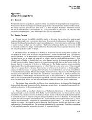
Appendix C<br />
Operation and Maintenance Considerations<br />
General ..................................................................................................................... C-1 C-1<br />
Design Considerations.............................................................................................. C-2 C-1<br />
Inspection ................................................................................................................. C-3 C-3<br />
Appendix D<br />
Data for Existing Tainter Gates<br />
ii
Chapter 1<br />
Introduction<br />
1-1. Purpose<br />
EM 1110-2-2702<br />
1 Jan 00<br />
This manual provides guidance for the design, fabrication, and inspection <strong>of</strong> spillway tainter gates, trunnion<br />
girder, and trunnion girder anchorage for navigation and flood control projects. Load and resistance factor<br />
design (LRFD) criteria are specified for design <strong>of</strong> steel components. Allowable stress design (ASD) criteria<br />
are provided in EM 1110-2-2105 and may be used only with prior approval <strong>of</strong> CECW-ET. Orthotropic shell,<br />
vertical framed, and stress skin-type tainter gates may be suitable in some locations but are not covered in this<br />
manual. Other types <strong>of</strong> control gates, including radial lock valves (reverse tainter valves) and sluice gates, may<br />
be referred to as tainter gates but also are not included in this manual.<br />
1-2. Applicability<br />
This manual applies to <strong>US</strong>ACE commands having responsibility for Civil Works projects.<br />
1-3. References<br />
References are provided in Appendix A.<br />
1-4. Distribution<br />
This publication is approved for public release; distribution is unlimited.<br />
1-5. Background<br />
a. The previous version <strong>of</strong> this document was published in 1966, and since that time, design and<br />
fabrication standards have improved. Load and resistance factor design has been adapted by many<br />
specification writing organizations including American Institute <strong>of</strong> Steel Construction (AISC) (1994) and<br />
American Association <strong>of</strong> State Highway and Transportation Officials (AASHTO) (1994). In addition to the<br />
development and adoption <strong>of</strong> LRFD criteria, general knowledge on detailing and fabrication to improve<br />
fracture resistance <strong>of</strong> structures has advanced greatly. Most <strong>of</strong> the research and development behind current<br />
fatigue and fracture provisions <strong>of</strong> AISC, American Welding Society (AWS), and AASHTO were accomplished<br />
during the 1970's. EM 1110-2-2105 has been revised recently (1993) to include new LRFD and fracture<br />
control guidance for hydraulic steel structures.<br />
b. Additionally, knowledge has expanded due to operational experience resulting in improved design<br />
considerations. During the late 1960s and early 1970s, many tainter gates on the Arkansas River exhibited<br />
vibration that led to fatigue failure <strong>of</strong> rib-to-girder welded connections. Study <strong>of</strong> these failures resulted in<br />
development <strong>of</strong> improved tainter gate lip and bottom seal details that minimize vibration. Tainter gates at<br />
various projects have exhibited operational problems and failures attributed to effects <strong>of</strong> trunnion friction not<br />
accounted for in original design. As a result <strong>of</strong> related studies, information regarding friction magnitude and<br />
structural detailing to withstand friction forces has been gained. Traditionally, tainter gates have been operated<br />
by lifting with wire rope or chains attached to a hoist located above the gate. More recently, hydraulic<br />
cylinders are being used to operate tainter gates due to economy, reduced maintenance, and advantages<br />
concerning operating multiple gates.<br />
1-1
EM 1110-2-2702<br />
1 Jan 00<br />
c. The intent for this publication is to update tainter gate design guidance to include the most recent and<br />
up-to-date criteria. General applications are discussed in Chapter 2. Guidance for LRFD and fracture control<br />
<strong>of</strong> structural components is provided in Chapter 3. Criteria for design <strong>of</strong> trunnion, gate anchorage, and<br />
trunnion is are given in Chapter 4 through 6. Considerations for operating equipment are discussed in<br />
Chapter 7. Chapter 8 provides general guidance on corrosion control. Appendix A includes references and<br />
Appendix B presents general design considerations and provides guidance on preparation <strong>of</strong> technical project<br />
specifications regarding fabrication and erection <strong>of</strong> tainter gates. Considerations for design to minimize<br />
operational problems are included in Appendix C. Appendix D provides data on existing tainter gates.<br />
1-6. Mandatory Requirements<br />
This manual provides design guidance for the protection <strong>of</strong> U.S. <strong>Army</strong> <strong>Corps</strong> <strong>of</strong> Engineers (<strong>US</strong>ACE)<br />
structures. In certain cases guidance requirements, because <strong>of</strong> their criticality to project safety and<br />
performance, are considered to be mandatory as discussed in ER 1110-2-1150. In this manual, the load and<br />
resistance factors for the design requirements <strong>of</strong> paragraphs 3-4, 4-4, 5-4, and 6-4 are mandatory.<br />
1-2
Chapter 2<br />
Applications<br />
2-1. General<br />
EM 1110-2-2702<br />
1 Jan 00<br />
a. Application. Controlled spillways include crest gates that serve as a movable damming surface allowing<br />
the spillway crest to be located below the normal operating level <strong>of</strong> a reservoir or channel. Information on the use<br />
<strong>of</strong> various crest gates and related spillway design considerations is provided in EM 1110-2-1603, EM 1110-2-<br />
1605, and EM 1110-2-2607. Tainter gates are considered to be the most economical, and usually the most<br />
suitable, type <strong>of</strong> gate for controlled spillways due to simplicity, light weight, and low hoist-capacity requirements.<br />
A tainter gate is a segment <strong>of</strong> a cylinder mounted on radial arms that rotate on trunnions anchored to the piers.<br />
Spillway flow is regulated by raising or lowering the gate to adjust the discharge under the gate. Numerous types<br />
<strong>of</strong> tainter gates exist; however, this manual includes guidance for the conventional tainter gate described in<br />
Chapter 3, paragraph 3-2. Figures 2-1 and 2-2 show photographs <strong>of</strong> actual dams with tainter gates. Figure 2-3<br />
presents a downstream view <strong>of</strong> a typical tainter gate.<br />
Pier (TYP)<br />
Tainter Gate (TYP)<br />
Figure 2-1. Overall view <strong>of</strong> navigation dam from downstream<br />
b. Tainter gate construction. Gates are composed primarily <strong>of</strong> structural steel and are generally <strong>of</strong> welded<br />
fabrication. Structural members are typically rolled sections; however, welded built-up girders may be required<br />
for large gates. Various components <strong>of</strong> the trunnion assembly and operating equipment may be <strong>of</strong> forged or cast<br />
steel, copper alloys, or stainless steel. Based on project requirements, trunnion girders are either posttensioned<br />
concrete girders or steel girders as described in Chapter 6.<br />
2-2. Advantages and Disadvantages <strong>of</strong> Tainter Gates vs Other Spillway Crest Gates<br />
a. Tainter gates have several unique advantages compared to other spillway gate types (lift gates, roller<br />
gates, hinged or flap gates).<br />
2-1
EM 1110-2-2702<br />
1 Jan 00<br />
2-2<br />
Vertical rib (typ)<br />
Girder<br />
Strut<br />
Downstream Vertical Truss<br />
Figure 2-2. Closeup view <strong>of</strong> tainter gate from downstream<br />
(1) The radial shape provides efficient transfer <strong>of</strong> hydrostatic loads through the trunnion.<br />
(2) A lower hoist capacity is required.<br />
(3) Tainter gates have a relatively fast operating speed and can be operated efficiently.<br />
(4) Side seals are used, so gate slots are not required. This reduces problems associated with cavitation,<br />
debris collection, and buildup <strong>of</strong> ice.<br />
(5) Tainter gate geometry provides favorable hydraulic discharge characteristics.<br />
b. Disadvantages include the following:<br />
(1) To accommodate location <strong>of</strong> the trunnion, the pier and foundation will likely be longer in the downstream<br />
direction than would be necessary for vertical gates. The hoist arrangement may result in taller piers especially<br />
when a wire rope hoist system is used. (Gates with hydraulic cylinder hoists generally require shorter piers than<br />
gates with wire rope hoists.) Larger piers increase cost due to more required concrete and will usually result in<br />
a less favorable seismic resistance due to greater height and mass.<br />
(2) End frame members may encroach on water passage. This is more critical with inclined end frames.
Figure 2-3. Downstream view <strong>of</strong> a typical tainter gate<br />
EM 1110-2-2702<br />
1 Jan 00<br />
(3) Long strut arms are <strong>of</strong>ten necessary where flood levels are high to allow the open gate to clear the water<br />
surface pr<strong>of</strong>ile.<br />
2-3. Use on <strong>Corps</strong> <strong>of</strong> Engineers Projects<br />
Spillway tainter gates are effectively applied for use on spillways <strong>of</strong> various projects due to favorable operating<br />
and discharge characteristics. Gates are used on flood control projects, navigation projects, hydropower projects,<br />
and multipurpose projects (i.e., flood control with hydropower). Although navigation and flood control tainter<br />
gates are structurally similar and generally have the same maximum design loads, the normal loading and function<br />
may be very different. In general, gates on navigation projects are subject to significant loading and discharge<br />
conditions most <strong>of</strong> the time, whereas gates on flood control projects are loaded significantly only during flood<br />
events. These differences may influence selection <strong>of</strong> the lifting hoist system, emphasis on detailing for resistance<br />
to possible vibration loading, and selection <strong>of</strong> a corrosion protection system.<br />
a. Navigation projects. Navigation projects are normally built in conjunction with a lock. Navigation<br />
gates are designed to maintain a consistent pool necessary for navigation purposes, while <strong>of</strong>fering minimum<br />
2-3
EM 1110-2-2702<br />
1 Jan 00<br />
resistance to flood flows. Gate sills are generally placed near the channel bottom, and during normal flows,<br />
damming to the required upper navigation pool elevation is provided by tainter gates. Under normal conditions,<br />
most gates on a navigation dam are closed, while several other gates are partially open to provide discharge<br />
necessary to maintain a consistent upper lock pool. During flood events, gates are open and flood flow is not<br />
regulated. The upper pool elevation <strong>of</strong>ten rises significantly during flood events and the open gate must clear the<br />
water surface pr<strong>of</strong>ile to pass accumulated drift. As a result, the trunnion elevation is <strong>of</strong>ten relatively high and the<br />
gate radius is <strong>of</strong>ten longer than gates designed for other applications. Under normal conditions, navigation gates<br />
are generally partially submerged and are significantly loaded with the upstream-downstream hydrostatic head.<br />
In addition, these gates are more likely to be subject to flow-induced vibration and cavitation. A typical cross<br />
section <strong>of</strong> a navigation dam with tainter gates is presented in Figure 2-4.<br />
b. Flood control and hydropower projects. Flood control projects provide temporary storage <strong>of</strong> flood flow<br />
and many projects include gated spillways to provide the capability to regulate outflow. On flood control projects<br />
with gated spillways, gate sills are generally located such that the gates are dry or only partially wet under normal<br />
conditions. In general, gates are exposed to the atmosphere and are subject to slight loads, if any. Only during<br />
infrequent flood events are gates loaded significantly due to increases in pool, and during subsequent discharge<br />
hydraulic flow-related conditions exist. Trunnions are typically located at an elevation approximately one-third<br />
the height <strong>of</strong> the gate above the sill. Some unique multipurpose projects (projects that provide flood control and<br />
reservoir storage) and most hydropower projects include aspects <strong>of</strong> flood control and navigation gates. Gates<br />
on these projects are normally subject to significant hydrostatic loading on the upstream side and may be used<br />
to regulate flow on a regular basis. A typical cross section <strong>of</strong> a flood control or hydropower dam with tainter<br />
gates is presented in Figure 2-5.<br />
2-4
2-5<br />
Figure 2-4. Typical navigation tainter gate<br />
EM 1110-2-2702<br />
1 Jan 00
2-6<br />
Figure 2-5. Typical flood control or hydropower tainter gate<br />
EM 1110-2-2702<br />
1 Jan 00
Chapter 3<br />
Tainter Gate Design<br />
3-1. Introduction<br />
EM 1110-2-2702<br />
1 Jan 00<br />
This chapter presents design guidance for the <strong>Corps</strong> <strong>of</strong> Engineers standard tainter gate described herein.<br />
The configuration for the standard gate has resulted from much practical and theoretical investigation <strong>of</strong><br />
alternatives and over 60 years <strong>of</strong> design and field experience with construction, operation, and<br />
maintenance. It is generally the simplest and most economical tainter gate configuration for most<br />
applications.<br />
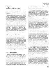
3-2. Geometry, Components, and Sizing<br />
a. Standard <strong>Corps</strong> <strong>of</strong> Engineers tainter gate geometry and components.<br />
(1) Primary gate components. The principal elements <strong>of</strong> a conventional tainter gate are the skin plate<br />
assembly, horizontal girders, end frames, and trunnions (Figure 3-1). The skin plate assembly, which<br />
forms a cylindrical damming surface, consists <strong>of</strong> a skin plate stiffened and supported by curved vertical<br />
ribs. Structurally, the skin plate acts compositely with the ribs (usually structural Tee sections) to form the<br />
skin plate assembly. The skin plate assembly is supported by the horizontal girders that span the gate<br />
width. The downstream edge <strong>of</strong> each rib is attached to the upstream flange <strong>of</strong> the horizontal girders. The<br />
horizontal girders are supported by the end frames. End frames consist <strong>of</strong> radial struts or strut arms and<br />
bracing members that converge at the trunnion which is anchored to the pier through the trunnion girder.<br />
The end frames may be parallel to the face <strong>of</strong> the pier (support the horizontal girders at the ends) or<br />
inclined to the face <strong>of</strong> the pier (support the horizontal girders at some distance from the end with cantilever<br />
portions at each end). The trunnion is the hinge upon which the gate rotates. The trunnion is supported by<br />
the trunnion girder which is addressed in Chapter 6.<br />
(2) Other structural members. Structural bracing members are incorporated to resist specific loads<br />
and/or to brace compression members. Certain bracing members are significant structural members, while<br />
others can be considered secondary members.<br />
(a) Horizontal girder lateral bracing. Cross bracing is generally placed between adjacent girders in a<br />
plane perpendicular to the girder axes, sometimes at several locations along the length <strong>of</strong> the girders. This<br />
horizontal girder lateral bracing may simply provide lateral bracing for the girders or may serve to carry<br />
vertical forces from the skin plate assembly to the end frame. Lateral bracing that is located in the same<br />
plane with the end frames is generally made up <strong>of</strong> significant structural members, while intermediate<br />
bracing located away from the end frames provides girder lateral stability and can be considered secondary<br />
members. The bracing located in the same plane with the end frames carries significant vertical forces<br />
from the skin plate assembly to the end frame and is <strong>of</strong>ten considered a part <strong>of</strong> the end frame (Figure 3-2).<br />
(b) Downstream vertical truss. The downstream vertical truss consists <strong>of</strong> bracing provided between<br />
the downstream flanges <strong>of</strong> the horizontal girders. Various configurations have been used depending on the<br />
gate size and configuration as shown by Figure 3-3. For gates with more than two girders, the downstream<br />
vertical truss does not lie in a single plane. Since the horizontal girders are arranged along the arc <strong>of</strong> the<br />
skin plate assembly, the downstream girder flanges do not lie in the same plane. Therefore,<br />
3-1
3-2<br />
Figure 3-1. Primary tainter gate components<br />
EM 1110-2-2702<br />
1 Jan 00
Figure 3-2. Horizontal girder lateral bracing<br />
EM 1110-2-2702<br />
1 Jan 00<br />
3-3
3-4<br />
Figure 3-3. Downstream vertical truss (typical configurations)<br />
EM 1110-2-2702<br />
1 Jan 00
EM 1110-2-2702<br />
1 Jan 00<br />
bracing members located between one pair <strong>of</strong> adjacent horizontal girders are not in the same plane as those<br />
between the next pair. This out-<strong>of</strong>-plane geometry is commonly ignored for design purposes.<br />
(c) End frame bracing. For the standard tainter gate configuration, bracing is provided for the end<br />
frame struts as shown by Figure 3-4. The end frame bracing members are ordinarily designed to brace the<br />
struts about the weak axis to achieve adequate slenderness ratios. As such, these members are considered<br />
secondary members. However, depending on their configuration and connection details, these bracing<br />
members may carry significant forces and act as primary members.<br />
(d) Trunnion tie. A trunnion tie is a tension member provided on some gates with inclined strut arms<br />
that is designed to resist lateral end frame reaction loads (loads that are parallel to trunnion pin axis or<br />
perpendicular to the pier). Trunnion ties are not generally provided on gates with parallel strut arms, since<br />
the lateral reaction loads are normally negligible (paragraph 3-5.a(2)(c)). The trunnion tie extends across<br />
the gate bay from one end frame to the other and is attached to each end frame near the trunnion (Figure<br />
3-5). The tie can be made up <strong>of</strong> a single member or multiple members depending on how it is attached<br />
to the end frames. Tubular members are <strong>of</strong>ten used.<br />
(3) Gate lifting systems. Two standard lifting arrangements presently recommended for new construction<br />
are the wire rope hoist and hydraulic hoist system. The wire rope system incorporates wire ropes that<br />
wrap around the upstream side <strong>of</strong> the skin plate assembly and attach near the bottom <strong>of</strong> the skin plate as<br />
shown in Figure 3-6. The hydraulic hoist system incorporates hydraulic cylinders that attach to the downstream<br />
gate framing, usually the end frames (Figure 3-7). Hoist layout geometry is addressed in paragraph<br />
3-2.c. Hoist loads and attachment details are addressed later in Chapter 3 and operating equipment<br />
is addressed in Chapter 7.<br />
b. Alternative framing systems. In the past, many alternatives to the standard framing system have<br />
been designed and constructed. Each <strong>of</strong> these configurations may be suitable for certain applications and a<br />
brief description <strong>of</strong> some configurations is provided for information. The design guidance and criteria<br />
presented herein are not necessarily applicable to these gates.<br />
(1) Vertical girders. For the standard gate configuration, fabrication at the trunnion and economy<br />
would normally limit the number <strong>of</strong> end frame strut arms to a maximum <strong>of</strong> four on each side. This in turn<br />
limits the design to four horizontal girders when each strut supports a horizontal girder. For tall gates,<br />
vertical girders have been used to simplify the end frame configuration. Curved vertical girders may be<br />
used to support several horizontal girders at each. Each vertical girder is supported by the corresponding<br />
end frame that may include two or more struts. The concept may be used with parallel or inclined end<br />
frames.<br />
(2) Vertically framed gates. In vertically framed gates, vertical girders support ribs that are placed<br />
horizontally. With this configuration, horizontal girders and vertical ribs are eliminated. As with vertical<br />
girder gates, the vertical girders can be supported by two or more struts. This system has been used on<br />
small gates and gates with low hydrostatic head.<br />
(3) Orthotropic gates. An alternative design approach is to design the gate as an orthotropic system.<br />
With the orthotropic approach, the skin plate, ribs, and horizontal girders are assumed to act as a stiffened<br />
shell. Typically, the ribs are framed into the horizontal girder webs. This approach can save material and<br />
gate weight, but fabrication and maintenance costs are <strong>of</strong>ten higher. Its use has been very limited.<br />
3-5
EM 1110-2-2702<br />
1 Jan 00<br />
Figure 3-4. End frame bracing (typical arrangements)<br />
3-6
Figure 3-5. Trunnion tie<br />
EM 1110-2-2702<br />
1 Jan 00<br />
3-7
EM 1110-2-2702<br />
1 Jan 00<br />
Figure 3-6. Example <strong>of</strong> wire rope hoist system<br />
(4) Stressed skin gates. Stressed skin gates are a type <strong>of</strong> orthotropic gate in which the skin plate<br />
assembly is considered to be a shell or tubular structure spanning between trunnion arms. The skin plate is<br />
stiffened with horizontal and vertical diaphragms and intermediate stiffening members (usually horizontal<br />
tee sections parallel to the intermediate or midlevel horizontal diaphragm). As with other orthotropic<br />
gates, this type <strong>of</strong> gate can save material and gate weight, but fabrication and maintenance costs are <strong>of</strong>ten<br />
higher.<br />
(5) Truss-type or space frame gates. Three-dimensional (3-D) truss or space frame gates were sometimes<br />
used in early tainter gate designs in the 1930s and 1940s. These early gates were designed as a series<br />
two-dimensional (2-D) trusses and were referred to as truss-type gates. They were typically as heavy or<br />
heavier than girder designs and fabrication and maintenance costs were very high. For this reason they<br />
were not adopted as a standard design. More recently, the use <strong>of</strong> computer designed 3-D space frame gates<br />
constructed with tubular sections has been investigated and may be practical in some situations.<br />
3-8
Figure 3-7. Hydraulically operated tainter gate<br />
EM 1110-2-2702<br />
1 Jan 00<br />
3-9
EM 1110-2-2702<br />
1 Jan 00<br />
(6) Overflow/submersible gates. These gates may be <strong>of</strong> the standard configuration but are designed<br />
to allow water to pass over the top the gate. Deflector plates are <strong>of</strong>ten provided on the downstream side <strong>of</strong><br />
the gate to allow water and debris to pass over the framing with minimized impact. Other gates have been<br />
designed to include a downstream skin plate, so the gate is completely enclosed. Vibration problems have<br />
been prevalent with this type gate.<br />
c. General gate sizing and layout considerations. The sizing <strong>of</strong> the gates is an important early step<br />
in the design process. Gate size affects other project components, project cost, operation, and maintenance<br />
<strong>of</strong> the project. The following paragraph includes various considerations that should be taken into account<br />
while selecting a practical and economical tainter gate size. Related guidance can be found in EMs 1110-<br />
2-1603, 1110-2-1605, and 1110-2-2607. Appendix D provides pertinent data for a number <strong>of</strong> existing<br />
tainter gates. Each project is unique and the gate size and configuration should be determined based on<br />
careful study <strong>of</strong> the project as a whole. The best alternative is not necessarily a gate with the lightest gate<br />
weight-to-size ratio.<br />
(1) Gate size. The hydraulic engineer will normally establish the limiting parameters for gate height<br />
and width. Within those limits, various height-to-width ratios should be studied to find the most suitable<br />
gate size for the project. The structural designer should coordinate closely with the hydraulic engineer in<br />
determining the basic limiting requirements for size and shape. The size, shape, and framing system <strong>of</strong> the<br />
gates should be selected to minimize the overall cost <strong>of</strong> the spillway, rather than the gate itself.<br />
Determination <strong>of</strong> gate size will also consider practical operation and maintenance considerations specific to<br />
the project.<br />
(2) Gate width. The gate width will be determined based on such factors as maximum desirable width<br />
<strong>of</strong> monoliths, length <strong>of</strong> spillway, bridge spans, drift loading, overall monolith stability, and loads on<br />
trunnions and anchorages. On navigation projects, the gates may be set equal to the width <strong>of</strong> the lock, so<br />
that one set <strong>of</strong> bulkheads can serve both structures. It is usually desirable to use high gates rather than low<br />
gates for a given discharge, since the overall spillway width is reduced and results in a more economical<br />
spillway.<br />
(3) Gate radius. The skin plate radius will normally be set equal to or greater than the height <strong>of</strong> the<br />
gate. The radius <strong>of</strong> the gate will also be affected by operational requirements concerning clearance<br />
between the bottom <strong>of</strong> the gate and the water surface pr<strong>of</strong>ile. This is <strong>of</strong>ten the case for navigation dams on<br />
rivers where the gate must clear the flood stage water surface pr<strong>of</strong>ile to pass accumulated drift. On such<br />
projects requiring larger vertical openings, it is common to use a larger radius, up to four times the gate<br />
height, to allow for a greater range <strong>of</strong> opening. This will require longer piers for satisfactory location <strong>of</strong><br />
the trunnion girder.<br />
(4) Trunnion location. It is generally desirable to locate the trunnion above the maximum flood water<br />
surface pr<strong>of</strong>ile to avoid contact with floating ice and debris and to avoid submergence <strong>of</strong> the operating<br />
parts. However, it is sometimes practical to allow submergence for flood events, especially on navigation<br />
dams. Designs allowing submergence <strong>of</strong> 5 to 10 percent <strong>of</strong> the time are common. Gates incorporating a<br />
trunnion tie should not experience trunnion submergence. If other considerations do not control, it will<br />
usually be advantageous to locate the trunnion so that the maximum reaction is approximately horizontal to<br />
the trunnion girder (typically about one-third the height <strong>of</strong> the gate above the sill for hydrostatic loading).<br />
This will allow for simplified design and construction by allowing the trunnion posttensioned anchorage to<br />
be placed in horizontal layers.<br />
3-10
EM 1110-2-2702<br />
1 Jan 00<br />
(5) Operating equipment location. The type and position <strong>of</strong> the gate lifting equipment can have a<br />
significant effect on gate forces as the gate is moved through its range <strong>of</strong> motion. As stated previously, the<br />
two gate lifting systems recommended for new construction are the wire rope hoist system and the<br />
hydraulic hoist system.<br />
(a) Wire rope hoist system. Generally, the most suitable layout for wire rope is one that minimizes the<br />
effects <strong>of</strong> lifting forces on the gate and lifting equipment. The three possible variations in cable layout<br />
include: 1) cable more than tangent to the skin plate, 2) cable tangent to the skin plate, and 3) cable less<br />
than tangent to the skin plate (Figure 3-8). Considering the gate and hoist system, the most ideal<br />
configuration is when the rope is pulled vertically and is tangent to the arc <strong>of</strong> the skin plate. For this<br />
condition, horizontal forces exerted to the hoist equipment are insignificant, and rope contact forces act<br />
radially on the gate. A nonvertical wire rope introduces a horizontal component <strong>of</strong> force that must be<br />
balanced by the operating equipment and associated connections. With a rope in the more-than-tangent<br />
condition, an edge reaction force exists at the top <strong>of</strong> the skin plate due to an abrupt change in rope<br />
curvature. This force affects the rope tension, trunnion reaction, and rib design forces. If the rope is in the<br />
less-than-tangent configuration, the rope force required to lift the gate increases exponentially as the<br />
direction <strong>of</strong> rope becomes further from tangent. The large lifting force affects the hoist and gate. Due to<br />
various constraints, some compromise on location <strong>of</strong> the hoist is usually required. Many gates have nonvertical<br />
wire ropes and many gates include ropes that are nontangent at or near the full, closed and/or full,<br />
opened positions.<br />
(b) Hydraulic cylinder hoist system. Many new gate designs utilize hydraulic cylinder hoist systems<br />
because they are usually cost effective. However, these systems have some disadvantages and are not<br />
suited for all applications. Close coordination with the mechanical design engineer is required to optimize<br />
the hoist system. A hydraulic cylinder hoist system generally comprises two cylinders, one located at each<br />
side <strong>of</strong> the gate. Each cylinder pivots on a trunnion mounted on the adjacent pier, and the piston rod is<br />
attached to the gate. The cylinder magnitude <strong>of</strong> force and its orientation will change continually<br />
throughout the range <strong>of</strong> motion. In determining the optimum cylinder position, the location <strong>of</strong> the cylinder<br />
trunnion and piston rod connection to the gate are interdependent. Generally, the piston rod connection<br />
position is selected and then the cylinder trunnion position is determined to minimize effects <strong>of</strong> lifting<br />
forces. For preliminary design layouts, it is <strong>of</strong>ten assumed that the cylinder will be at a 45-deg angle from<br />
horizontal when the gate is closed, although optimization studies may result in a slightly different<br />
orientation. Generally, the most suitable location for the piston rod connection is on the gate end frame at<br />
or near the intersection <strong>of</strong> a bracing member and strut. It is preferable to have the piston rod connection<br />
above tailwater elevations that are consistent with the gate operating versus tailwater stage schedule;<br />
however, partial submergence may be acceptable for navigation projects. The connection location<br />
influences the gate trunnion reaction forces due to simple static equilibrium. When the connection is<br />
located upstream <strong>of</strong> the gate center <strong>of</strong> gravity, the dead load reaction at the gate trunnion will be downward<br />
while the gate is lifted <strong>of</strong>f the sill. However, if the connection is downstream <strong>of</strong> the center <strong>of</strong> gravity, the<br />
reaction at the gate trunnion will act upward while the gate is lifted <strong>of</strong>f the sill.<br />
(6) Other sizing considerations. The face <strong>of</strong> gate and the stop log slots should be located far enough<br />
apart to permit the installation <strong>of</strong> maintenance scaffolding. Spillway bridge clearance is a factor in<br />
determining the gate radius and the trunnion location. Operating clearances from the bridge and the<br />
location <strong>of</strong> the hoist will usually require that the sill be placed somewhat downstream from the crest, but<br />
this distance should be as small as possible to economize on height <strong>of</strong> gate and size <strong>of</strong> pier. Additional<br />
considerations could include standardization <strong>of</strong> gate sizes on a project involving multiple spillways. The<br />
standardization <strong>of</strong> sizes could result in savings by eliminating multiple sets <strong>of</strong> bulkheads, standardizing<br />
machinery, and reducing stored replacement parts, etc.<br />
3-11
3-12<br />
Figure 3-8. Loads due to various wire rope configurations<br />
EM 1110-2-2702<br />
1 Jan 00
3-3. Material Selection<br />
EM 1110-2-2702<br />
1 Jan 00<br />
Structural members shall be structural steel. Embedded metals, including the side and bottom seal plates,<br />
should be corrosion-resistant stainless steel. Material selection for trunnion components is discussed in<br />
Chapter 4, and considerations for corrosion are discussed in Chapter 8. Table 3-1 provides a general<br />
reference for material selection <strong>of</strong> various tainter gate components, including American Society for Testing<br />
and Materials (ASTM) standards, given normal conditions. Material selection recommendations for<br />
various civil works structures including tainter gates is provided by Kumar and Odeh (1989).<br />
Table 3-1<br />
Tainter Gate Component Material Selection<br />
Component Material Selection<br />
Skin plate, girders, trunnion girders, lifting bracket, wear plates, end<br />
frames<br />
ASTM A36 or ASTM A572 Steel<br />
Trunnion pin ASTM A705, type 630 condition H 1150<br />
steel forging 1,2<br />
stainless steel 3<br />
ASTM A27 or A148 cast steel<br />
Trunnion bushing ASTM B148 aluminum bronze<br />
ASTM B 22 manganese bronze or leaded<br />
tin bronze<br />
Self-lubricating bronze 4<br />
Trunnion hub ASTM A27 cast steel<br />
ASTM A668 steel forging 2<br />
Trunnion yoke ASTM A27 cast steel<br />
structural steel weldment<br />
Seal plates and bolts 304 stainless steel<br />
Lifting rope 308 stainless steel<br />
J-seal keeper plate 410 stainless steel<br />
galvanized steel<br />
Posttensioning anchorage steel ASTM A772 Steel<br />
Reinforcing steel ASTM A615 grade 60 steel<br />
Deflector plates Ultra high molecular weight polyethylene<br />
1<br />
Pin may be clad with corrosion resistant steel.<br />
2<br />
If welded, carbon content not to exceed 0.35 percent.<br />
3<br />
Type <strong>of</strong> stainless steel should be resistant to galling and crevice corrosion.<br />
4<br />
Use with stainless steel pin.<br />
3-4. Design Requirements<br />
Tainter gate structural components shall be designed based on load and resistance factor design (LRFD)<br />
principles per EM 1110-2-2105. LRFD is a method <strong>of</strong> proportioning structures such that no applicable<br />
limit state is exceeded when the structure is subjected to all appropriate design load combinations. (See<br />
EM 1110-2-2105 and AISC (1994) for a more complete description <strong>of</strong> LRFD.)<br />
3-13
EM 1110-2-2702<br />
1 Jan 00<br />
where<br />
3-14<br />
a. Design basis. The basic safety check in LRFD may be expressed mathematically as<br />
Q Rn<br />
(3-1)<br />
i<br />
ni<br />
i = load factors that account for variability in the corresponding loads<br />
Qni = nominal load effects defined herein<br />
= reliability factor as defined in EM 1110-2-2105<br />
= resistance factor that reflects the uncertainty in the resistance for the particular limit state and, in<br />
a relative sense, the consequence <strong>of</strong> attaining the limit state.<br />
Rn = nominal resistance.<br />
For the appropriate limit states (paragraph 3-4.c), all structural components shall be sized such that the<br />
design strength Rn is at least equal to the required strength iQni. The design strength shall be<br />
determined as specified in paragraph 3-4.c. The required strength must be determined by structural<br />
analysis for the appropriate load combinations specified in paragraph 3-4.b.<br />
b. Load requirements.<br />
(1) Loads. Loads that are applicable to tainter gate design include gravity loads, hydrostatic loads,<br />
operating loads, ice and debris loads, and earthquake loads. Reactions are not listed below or in the load<br />
cases. Reactions loads are not factored since they are determined from equilibrium with factored loads<br />
applied. As a result, reaction forces reflect the load factors <strong>of</strong> the applied loads.<br />
(a) Gravity loads. Gravity loads include dead load or weight <strong>of</strong> the gate (D), mud weight (M), and ice<br />
weight (C), and shall be determined based on site-specific conditions.<br />
(b) Hydrostatic loads. Hydrostatic loads consist <strong>of</strong> hydrostatic pressure on the gate considering both<br />
upper and lower pools. Three levels <strong>of</strong> hydrostatic loads are considered. The maximum hydrostatic load<br />
H1 is defined as the maximum net hydrostatic load that will ever occur. The design hydrostatic load H2 is<br />
the maximum net hydrostatic load considering any flood up to a 10-year event. The normal hydrostatic<br />
load H3 is the temporal average net load from upper and lower pools, i.e., the load that exists from pool<br />
levels that are exceeded up to 50 percent <strong>of</strong> the time during the year.<br />
(c) Gate lifting system (operating machinery) loads. Operating machinery is provided to support gates<br />
during lifting or lowering operations. Under normal operating conditions, the machinery provides forces<br />
necessary to support the gate, and for the load cases described herein, these forces are treated as reaction<br />
forces. Loads Q are machinery loads for conditions where the machinery exerts applied forces on an<br />
otherwise supported gate (paragraph 3-4.b(2)(f)). There are three levels <strong>of</strong> loads applied by the operating<br />
machinery to the gate. The hydraulic cylinder maximum downward load Q1 is the maximum compressive<br />
downward load that a hydraulic hoist system can exert if the gate gets jammed while closing or when the<br />
gate comes to rest on the sill. The hydraulic cylinder at-rest load Q2 is the downward load that a hydraulic
EM 1110-2-2702<br />
1 Jan 00<br />
cylinder exerts while the gate is at rest on the sill (due to cylinder pressure and the weight <strong>of</strong> the piston and<br />
rod). Loads Q1 and Q2 do not exist for wire rope hoist systems. The maximum upward operating<br />
machinery load Q3 is the maximum upward load that can be applied by the wire rope or hydraulic hoist<br />
systems when a gate is jammed or fully opened. The gate lifting systems exert forces on specific gate<br />
members whether the forces are reactions or applied loads. For example, where the wire rope bears on the<br />
skin plate, the rope exerts a contact pressure (line load) on the skin plate. The contact pressure force is<br />
equal to the rope tension force divided by the gate radius. If the wire rope is not tangent to the skin plate,<br />
the rope will exert an additional concentrated load on the gate (Figure 3-8.). Concentrated forces that<br />
typically vary with gate position in magnitude and direction are present at the attachment points for both<br />
gate lifting systems. Operating machinery loads must be quantified in consultation with the mechanical<br />
engineer that designs the machinery. Determination <strong>of</strong> load magnitudes and suggested coordination are<br />
discussed in Chapter 7.<br />
(d) Ice-impact load I. The ice-impact load is specified to account for impact <strong>of</strong> debris (timber, ice, and<br />
other foreign objects) or lateral loading due to thermal expansion <strong>of</strong> ice sheets. Additionally, this load<br />
provides the overall structure with a margin <strong>of</strong> safety against collapse under barge impact. (Barge impact<br />
is an accidental event that is not practical to design for and is not specifically considered in design). I is<br />
specified as a uniform distributed load <strong>of</strong> 73.0 KN/M (5.0 kips/ft) that acts in the downstream direction<br />
and is applied along the width <strong>of</strong> the gate at the upper pool elevation.<br />
(e) Side-seal friction load Fs. Loads exist along the radius <strong>of</strong> the skin plate because <strong>of</strong> friction<br />
between the side seals and the side-seal plate when the gate is opening or closing. The friction force per<br />
unit length along the skin plate edge dFs/dl is equal to the product <strong>of</strong> the coefficient <strong>of</strong> friction and normal<br />
force between the seal plates and the side seals. For rubber seals, a coefficient <strong>of</strong> friction (s) equal to 0.5<br />
is recommended. (Seals that have Teflon rubbing surfaces provide a lower coefficient <strong>of</strong> friction and are<br />
recommended for serviceability. However, wear <strong>of</strong> the Teflon is a concern, and applying a lower<br />
coefficient <strong>of</strong> friction for design purposes is not recommended.) The normal force on the side seal is a<br />
function <strong>of</strong> the preset force in the seal and the hydrostatic pressure on the surface <strong>of</strong> the seal. For normal<br />
tainter gate configurations, side-seal friction can be approximated by Equation 3-2 (Figure 3-9).<br />
where<br />
d § h ·<br />
= P S l + ¨l<br />
+ h<br />
s P s J w 1 l ¸<br />
(3-2)<br />
2 © 2 ¹<br />
F s<br />
2<br />
s = coefficient <strong>of</strong> side-seal friction<br />
l = total length <strong>of</strong> the side seal<br />
l1 = length <strong>of</strong> the side seal from the headwater to the tailwater elevations or bottom <strong>of</strong> the<br />
seal if there is no tailwater on the gate<br />
l2 = length <strong>of</strong> the side seal from the tailwater elevation to the bottom <strong>of</strong> the seal (equals zero if there<br />
is no tailwater on the gate)<br />
S = force per unit length induced by presetting the seal and can be approximated as<br />
3-15
EM 1110-2-2702<br />
1 Jan 00<br />
Figure 3-9. Standard side-seal arrangement and friction load<br />
3-16
S = 3EI<br />
d 3<br />
G<br />
w = unit weight <strong>of</strong> water<br />
, where is the seal preset distance<br />
d = width <strong>of</strong> the J seal exposed to upper pool hydrostatic pressure (Figure 3-9)<br />
EM 1110-2-2702<br />
1 Jan 00<br />
h = vertical distance taken from the headwater surface to the tail water surface or the bottom <strong>of</strong> the<br />
seal if there is no tailwater on the gate (Figure 3-9)<br />
(f) Trunnion pin friction loads Ft. During opening or closing <strong>of</strong> gates, friction loads exist around the<br />
surface <strong>of</strong> the trunnion pin between the bushing and the pin and at the end <strong>of</strong> the hub between the hub<br />
bushing and side plate (yoke plate for yoke mounted pins) (Refer to Chapter 4 for description <strong>of</strong> trunnion<br />
components.). These friction loads result in a trunnion friction moment Ft about the pin that must be<br />
considered in design. The friction moment around the pin is a function <strong>of</strong> a coefficient <strong>of</strong> friction, the<br />
trunnion reaction force component R that acts normal to the surface <strong>of</strong> the pin (parallel to the pier face),<br />
and the radius <strong>of</strong> the pin. The friction moment at the end <strong>of</strong> the hub is a function <strong>of</strong> a coefficient <strong>of</strong><br />
friction, the trunnion reaction force component Rz that acts normal to the end <strong>of</strong> the pin (normal to the pier<br />
face), and the average radius <strong>of</strong> the hub. The reaction forces R and Rz are discussed in paragraphs<br />
3-5.a(2)(c) and 3-5.a(3). A coefficient <strong>of</strong> friction <strong>of</strong> 0.3 is an upper bound for design purposes.<br />
This is a conservative value that applies for any bushing material that may be slightly worn or improperly<br />
maintained. A realistic coefficient <strong>of</strong> friction for systems with lubricated bronze or aluminum bronze<br />
bushings is 0.1 to 0.15. The designer should ensure that detailed criteria are specified in project operations<br />
and maintenance manuals to ensure that trunnion systems are properly maintained.<br />
(g) Earthquake design loads E. Earthquake design loads are specified based on an operational basis<br />
earthquake (OBE) with a 144-year mean recurrence interval. For gate design, the direction <strong>of</strong> earthquake<br />
acceleration is assumed to be parallel to the gate bay centerline (i.e., it is assumed that the effects <strong>of</strong><br />
vertical acceleration and acceleration perpendicular to the gate bay are comparatively negligible).<br />
Earthquake forces include mass inertia forces and hydrodynamic forces <strong>of</strong> water on the structure. When a<br />
tainter gate is submerged, the inertial forces due to structural weight, ice, and mud are insignificant when<br />
compared with the hydrodynamic loads and can be ignored. For load case 1 (paragraph 3-4.b(2)(a)), the<br />
structure is submerged, and E shall be based on inertial hydrodynamic effects <strong>of</strong> water moving with the<br />
structure. For the structural member in question, E is determined based on the pressure that acts over the<br />
tributary area <strong>of</strong> the particular member. The hydrodynamic pressure may be estimated by Equation 3-3<br />
(Westergaard 1931). This equation applies for water on the upstream and downstream sides <strong>of</strong> the<br />
structure.<br />
where<br />
7<br />
= <br />
w a Hy<br />
(3-3)<br />
8<br />
p c<br />
p = lateral hydrodynamic pressure at a distance y below the pool surface<br />
w = unit weight <strong>of</strong> water<br />
3-17
EM 1110-2-2702<br />
1 Jan 00<br />
3-18<br />
H = reservoir pool depth (to bottom <strong>of</strong> dam) on upstream or downstream side <strong>of</strong> the structure<br />
ac = maximum base acceleration <strong>of</strong> the dam due to the OBE (expressed as a fraction <strong>of</strong> gravitational<br />
acceleration)<br />
For load case 5 (paragraph 3-4.b(2)(e)), water is not on the structure, and E is due to mass inertia forces <strong>of</strong><br />
the structure, ice, and mud.<br />
where<br />
E M<br />
= ac<br />
W D, C,<br />
(3-4)<br />
WD,C,M = weight <strong>of</strong> the portion <strong>of</strong> the structure, ice, and mud that are supported by the member in<br />
question.<br />
(h) Wave load WA. Wave loads are site specific and should be determined in consultation with the<br />
project hydraulic engineer. Guidance on development <strong>of</strong> wave loading is provided in the Shore Protection<br />
Manual (1984).<br />
(i) Wind load W. Wind loads are site specific and should be calculated in accordance with ASCE<br />
(1995) but not more than 2.4 KPa (50 psf). Wind loads are small when compared to hydrostatic loads and<br />
only affect gate reactions when the gate is in an open position.<br />
(2) Load cases. Tainter gates shall be designed considering the strength requirements for each <strong>of</strong> the<br />
following load cases and corresponding load combinations. The most unfavorable effect on various gate<br />
components may occur when one or more <strong>of</strong> the loads in a particular load combination is equal to zero.<br />
Various conditions are described for the cases <strong>of</strong> gate in the closed position (load case 1), gate operating<br />
(load case 2 and load case 3), gate jammed (load case 4), and gate fully opened (load case 5). The<br />
operating machinery may include forces in each load case; however, these forces are treated as gate reactions<br />
in some cases. As a result, the load Q does not appear in some load cases (paragraph 3-4.b(2)(f)).<br />
(a) Load case 1: Gate closed. Load combinations for this load case (Equations 3-5, 3-6, and 3-7)<br />
apply when the gate is in the closed position.<br />
1.4 H + 1.2D + 1.6(C + M) + 1.2 Q<br />
1 2 (3-5)<br />
1.4 H 2<br />
1<br />
2 A<br />
2 I<br />
+ 1.2D + 1.6(C + M) + [ 1.2 Q or ( 1 . 2Q<br />
1.2W ) or ( 1.<br />
2Q<br />
k I) ]<br />
(3-6)<br />
1.2 H 3 + 1.2D + 1.6(C+ M) + 1.0E<br />
(3-7)<br />
1) Extreme pool condition. Equation 3-5 describes the condition where the maximum hydrostatic<br />
load H1 is applied, gravity loads D, C, and M exist, and the hydraulic cylinders exert the at-rest load Q2.<br />
(For gates with wire rope hoists, Q2 does not exist.) It is assumed that the likelihood <strong>of</strong> the simultaneous<br />
occurrence <strong>of</strong> H1 and WA or I or E is negligible.<br />
2) Operating pool condition. Equation 3-6 describes the condition for which the moderate hydrostatic<br />
load H2 acts in combination with Q1 or WA or I. Gravity loads D, C, and M always exist, and it is<br />
assumed that Q1, WA, and I will not occur at the same time. The load Q2 will likely always exist with W or
EM 1110-2-2702<br />
1 Jan 00<br />
I. The I load factor kI shall be equal to 1.6 when considering ice load due to thermal expansion and 1.0<br />
when considering impact <strong>of</strong> debris.<br />
3) Earthquake condition. Equation 3-7 describes the condition where the normal hydrostatic load H3<br />
acts in combination with earthquake loading E and gravity loads D, C, and M exist.<br />
(b) Load case 2: Gate operating with two hoists. Load combinations for this load case (Equations 3-8<br />
and 3-9) represent the condition when the gate is opening or closing with both hoists functional. Operating<br />
machinery loads Q are not listed in these load combinations, because it is assumed that the hoists are gate<br />
supports that will include reaction forces (paragraph 3-4.b(2)(f)). This load case does not include E<br />
because it is assumed that the likelihood <strong>of</strong> opening or closing the gate at the same time an earthquake<br />
occurs is negligible. Effects on members forces should be checked considering the entire operating range<br />
(any position between the sill and the upper gate stops) for gates either opening or closing.<br />
1.4 H 1 + 1.2D + 1.6(C+ M) + 1.4 F S + 1.0 F t (3-8)<br />
1.4 H 2 + 1.2D + 1.6(C+ M) + 1.4 F S + 1.0 F t + (1.2W A or k I I)<br />
(3-9)<br />
1) Extreme pool condition. Equation 3-8 (similar to Equation 3-5) describes the condition where the<br />
maximum hydrostatic load H1 is applied, gravity loads D, C, and M exist, and friction loads Fs and Ft exist<br />
due to gate motion. It is assumed that the likelihood <strong>of</strong> the simultaneous occurrence <strong>of</strong> H1 and WA or I or E<br />
is negligible.<br />
2) Operating pool condition. Equation 3-9 (similar to Equation 3-6) describes the condition for<br />
which the moderate hydrostatic load H2 acts in combination with WA or I. Gravity loads D, C, and M exist,<br />
and due to gate motion, friction loads Fs and Ft are applied. In the determination <strong>of</strong> H2, the lower pool<br />
elevation will include a hydrodynamic reduction due to flow <strong>of</strong> water under the gate. The magnitude <strong>of</strong><br />
hydrodynamic reduction should be determined in consultation with the project hydraulic engineer. As<br />
described for Equation 3-6, kI shall be equal to 1.6 for ice and 1.0 for debris.<br />
(c) Load case 3: Gate operating with one hoist. The load combination described by Equation 3-10<br />
applies for the case where the gate is operated with only one hoist (subsequent to failure <strong>of</strong> the other hoist).<br />
Effects on members forces should be checked for all gate positions throughout the operating range for the<br />
gate either opening or closing.<br />
1.4 H 2 + 1.2D + 1.6(C+ M) + 1.4 F S + 1.0 F t (3-10)<br />
For this case, the moderate hydrostatic load H2 is applied, gravity loads D, C, and M exist, and friction<br />
loads Fs and Ft exist due to gate motion. In the determination <strong>of</strong> H2, the lower pool elevation will include a<br />
hydrodynamic reduction due to flow <strong>of</strong> water under the gate (must be coordinated with the project<br />
hydraulic engineer). The effects <strong>of</strong> H1, WA, I, or E are not considered for this load case, since it is<br />
assumed that the likelihood <strong>of</strong> the simultaneous occurrence one <strong>of</strong> these loads and the failure <strong>of</strong> one hoist<br />
is negligible. Design considerations for this condition are provided in paragraph 3-5.e and serviceability<br />
considerations are discussed in paragraph 3-6.b(1).<br />
(d) Load case 4: Gate jammed. The load combination <strong>of</strong> Equation 3-11 accounts for the possible<br />
condition where one hoist fails, and the gate becomes jammed between piers due to twist <strong>of</strong> the gate (such<br />
that one end frame is higher than the other). Effects on members forces should be checked with the gate<br />
jammed at positions throughout the operating range.<br />
3-19
EM 1110-2-2702<br />
1 Jan 00<br />
3-20<br />
1.4 3<br />
1<br />
H 2 + 1.2D + 1.6(C + M) + (1.2Q<br />
or 1.2Q<br />
)<br />
(3-11)<br />
For this case, the moderate hydrostatic load H2 is applied in combination with the maximum machinery<br />
load Q3 (for wire rope hoists or hydraulic hoists) or Q1 (for hydraulic hoists), and gravity loads D, C, and<br />
M exist. It is assumed that only one hoist is functional. In the determination <strong>of</strong> H2, the lower pool<br />
elevation will include a hydrodynamic reduction due to flow <strong>of</strong> water under the gate (must be coordinated<br />
with the project hydraulic engineer). The effects <strong>of</strong> H1, WA, I, or E are not considered for this load case,<br />
since it is assumed that the likelihood <strong>of</strong> the simultaneous occurrence one <strong>of</strong> these loads while the gate is<br />
jammed is negligible.<br />
(e) Load case 5: Gate fully opened. The load combination <strong>of</strong> Equation 3-12 accounts for the condition<br />
where the gate is fully opened (raised to the gate stops) with wind, earthquake, or operating equipment<br />
loads.<br />
k D D + 1.6(C + M) + (1.3W or 1.0E or 1.2 Q 3 ) (3-12)<br />
For this case, it is assumed that the gate is raised above the pool, so effects <strong>of</strong> H, WA, and I are not<br />
included. Effects <strong>of</strong> Q3 oppose gravity load effects, and effects <strong>of</strong> W or E may add to or oppose gravity<br />
load effects. When Q3 is considered, or when effects W or E oppose those <strong>of</strong> gravity, C and M should be<br />
equal to 0 and the load factor kD is equal to 0.9. When the direction <strong>of</strong> W or E is such that their effect<br />
increases gravity load effects, kD is equal to 1.2 and C and M should be considered.<br />
(f) Assumptions on support or loading <strong>of</strong> gate lifting systems (operating machinery). The load<br />
combinations included herein were developed for gate design based on various assumptions on loading and<br />
support conditions. (See Chapter 7 for discussion on criteria regarding load and operational requirements<br />
for operating machinery.) These assumptions must be considered in structural analysis <strong>of</strong> gate components<br />
(paragraph 3-5). For a tainter gate to be stable, rotational restraint must be provided by a suitable support.<br />
It is assumed that this support is the sill when the gate is closed (case 1), the hoists when the gate is<br />
operated (case 2 and case 3), the pier or some obstruction at the gate sides when the gate is jammed<br />
(case 4), and the hoists or the gate stops when the gate is fully opened (case 5). In load cases 2, 3, and<br />
some applications <strong>of</strong> 5, operating machinery loads Q are not included, since for these cases, the hoists are<br />
supports. The hoists provide reaction forces which are a function <strong>of</strong> all other gate loads. In load cases 1,<br />
4, and some applications <strong>of</strong> 5, where the gate is supported by something other than the hoists, any force<br />
exerted by the hoists is an external load on the gate Q.<br />
c. Limit states and design strength for individual members. EM 1110-2-2105 requires that strength<br />
and serviceability limit states be considered in the design <strong>of</strong> tainter gate structural components. Strength<br />
limit states include general yielding, instability, fatigue, and fracture. The design strength for each<br />
applicable limit state Rn is calculated as the nominal strength Rn, multiplied by a resistance factor and<br />
a reliability factor . Except as modified herein, limit states, nominal strength Rn, and resistance factors <br />
shall be in accordance with AISC (1994). For normal conditions, shall be equal to 0.9. For gates that<br />
are normally submerged and whose removal would disrupt the entire project, or for gates in brackish water<br />
or sea water, shall be equal to 0.85. Fatigue and fracture design requirements are included in paragraph<br />
3-8 and EM 1110-2-2105. Serviceability requirements for tainter gates are specified in paragraph<br />
3-6. The following paragraphs provide specific guidance for the design <strong>of</strong> skin plate, ribs, girders,<br />
and end frame members.<br />
(1) Skin plate. The skin plate shall be sized such that the maximum calculated stress is less than the<br />
yield limit state <strong>of</strong> bFy. In determining the required strength, all load cases in paragraph 3-4.b shall be
EM 1110-2-2702<br />
1 Jan 00<br />
considered; however, the ice-impact load I may be set equal to zero at the designer’s option. This is<br />
frequently done, with the intent <strong>of</strong> allowing local damage to the skin plate for very infrequent loading<br />
events rather than increasing the gate weight.<br />
(2) Rib members. Ribs shall be sized such that the maximum calculated moment Mu is less than the<br />
nominal bending strength <strong>of</strong> bMn. In determining the required strength Mu, all load cases in paragraph<br />
3-4.b shall be considered. For load cases 2, 3, and 4, the maximum effect will normally occur<br />
assuming that the gate is near the closed position.<br />
(3) Girders. Girders shall be designed as beams or plate girders in accordance with AISC (1994). In<br />
determining the required strength, all load cases in paragraph 3-4.b shall be considered. For load cases 2,<br />
3, and 4, the maximum effect will normally occur assuming that the gate is near the closed position.<br />
(4) End frame. Struts and bracing members shall be designed as members under combined forces in<br />
accordance with AISC (1994). For gates not braced against side sway, struts shall be sized to avoid side<br />
sway frame buckling (lateral buckling <strong>of</strong> gate toward pier face, see paragraph 3-5.a(2)). In determining the<br />
required strength, all load cases in paragraph 3-4.b shall be considered.<br />
(5) Secondary bracing members. The minimum axial design load in all bracing members shall be<br />
2 percent <strong>of</strong> the total axial compression force or <strong>of</strong> the flexural compressive force in the compression<br />
flange <strong>of</strong> the corresponding braced member. Trunnion hub flange plates shall have adequate design<br />
strength to resist the required flexural and axial loads between the struts and the trunnion hub.<br />
3-5. Analysis and Design Considerations<br />
This paragraph includes guidance on design <strong>of</strong> tainter gate structural components (Chapters 4 through 6<br />
provide guidance for the design <strong>of</strong> the trunnion and trunnion girder). The design and behavior <strong>of</strong> individual<br />
structural components are interrelated. The gate design should be optimized to achieve the most<br />
economical design overall, not necessarily to provide the most efficient geometry and member sections for<br />
each component. A large percentage <strong>of</strong> total gate cost is associated with the fabrication <strong>of</strong> the skin plate<br />
assembly. Therefore, the design process should be tailored to minimize the cost <strong>of</strong> the skin plate assembly<br />
considering the most normal load conditions. The required strength (design forces) and deflections for all<br />
structural components must be determined by structural analysis. Three-dimensional (3-D) analyses or<br />
more approximate (generally conservative) two-dimensional (2-D) analyses may be conducted. All<br />
analytical models must include boundary conditions that are consistent with load requirements specified in<br />
paragraph 3-4.b. Paragraph 3-5.a includes a description <strong>of</strong> acceptable 2-D models (various modeling alternatives<br />
exist), and the remainder <strong>of</strong> paragraph 3-5 provides general design considerations.<br />
a. Two-dimensional analytical models. In the design <strong>of</strong> tainter gate structural members, it has been<br />
common practice to model the 3-D behavior with several independent 2-D models. With the 2-D<br />
approach, the overall behavior is simulated by modeling separately the behavior <strong>of</strong> the skin plate assembly<br />
(composed <strong>of</strong> the skin plate and supporting ribs), horizontal girder frames (composed <strong>of</strong> a horizontal girder<br />
and the two adjacent struts), vertical end frames (composed <strong>of</strong> struts and braces), and the vertical<br />
downstream truss. Analysis <strong>of</strong> the 2-D models is interdependent. Various loads on one model can be<br />
reactions from another (girder frame loads are obtained from the rib model reactions), and many <strong>of</strong> the<br />
same loads are applied to each model. Additionally, struts include member forces from separate models<br />
(the strong axis flexural behavior <strong>of</strong> the struts is simulated with the girder frame model, and axial and weak<br />
axis flexural forces are provided by the end frame model). An alternative for each 2-D model is described<br />
in the following subsections. In the discussion for each model, loads for all load conditions are described.<br />
3-21
EM 1110-2-2702<br />
1 Jan 00<br />
For design analysis, load combinations and associated load factors should be applied accordingly. Various<br />
loads that are applied to the models (such as the gate reaction loads including sill load RS and the wire rope<br />
pressure load RQ/r) are not factored, since they are a function <strong>of</strong> other factored loads.<br />
(1) Skin plate assembly. For the 2-D approximate model, the skin plate and ribs are assumed to have<br />
zero curvature. The skin plate serves two functions. First, each unit width <strong>of</strong> skin plate is assumed to act<br />
as a continuous beam spanning the ribs in the horizontal direction (Figure 3-10). Second, the skin plate<br />
acts as the upstream flange <strong>of</strong> the ribs. The ribs, with the skin plate flange, are continuous vertical beams<br />
that are supported by the horizontal girders (Figure 3-11). A portion <strong>of</strong> the skin plate is considered to act<br />
as the upstream flange <strong>of</strong> the rib (paragraph 3-5.b(2)).<br />
(a) Boundary conditions. Boundary conditions consist <strong>of</strong> simple supports located at each rib for the<br />
skin plate and at each girder for the rib members.<br />
(b) Loads. Loading on the skin plate assembly consists <strong>of</strong> various combinations <strong>of</strong> factored loads and<br />
gate reaction loads. Factored loads consist <strong>of</strong> 1.2H or 1.4H, 1.2 WA, 1.0E, kII, and 1.2Q3/r, and gate<br />
reaction loads include Rs and RQ/r. H, WA, E, I, and Q3 are defined in paragraph 3-4.b, r is the gate radius,<br />
Rs is the sill reaction load at the bottom <strong>of</strong> the skin plate (load case 1 gate closed), and RQ is the wire rope<br />
reaction load (for load cases 2 and 3 for gates with a wire rope hoist). The factored loads shall be applied<br />
in accordance with paragraph 3-4.b(2). Gate reaction loads RS and RQ/r are determined by equilibrium <strong>of</strong><br />
the end frame model for each appropriate load condition (paragraph 3-5.a(3)) and are not factored since<br />
they are a function <strong>of</strong> other factored loads. For skin plate design, loads are determined based on a unit<br />
width <strong>of</strong> plate, and it is not considered necessary to include I and RS. For the rib model, the magnitude for<br />
loads is determined based on the tributary area <strong>of</strong> the rib. For each rib, the tributary portion <strong>of</strong> RS is<br />
resolved into a radial component that is applied as a concentrated load at the end <strong>of</strong> the rib cantilever, and a<br />
tangential component that is applied as an axial force. Although not applied directly, all loads described in<br />
paragraph 3-4.b can affect rib member forces, since the reaction forces at the sill or under the wire rope<br />
include the effects <strong>of</strong> trunnion friction Ft, hydraulic machinery loads Q1 and Q2, and gravity loads C, M,<br />
and D as defined in paragraph 3-4.b.<br />
(c) Results. Analysis <strong>of</strong> the skin plate model will yield the calculated stresses and out-<strong>of</strong>-plane<br />
deflections necessary to size the skin plate in accordance with paragraphs 3-4.c(1) and 3-6. Analysis <strong>of</strong> the<br />
rib model yields the calculated moments necessary for rib design in accordance with paragraph 3-4.c and<br />
reactions are the girder loading for the girder frame model.<br />
(2) Girder frame model. The 2-D analytical model is a single-story frame consisting <strong>of</strong> beam<br />
members that simulate the horizontal girder and two columns that represent the corresponding end frame<br />
struts (Figure 3-12). The strong axes <strong>of</strong> the struts are oriented to resist flexural forces in the plane <strong>of</strong> the<br />
frame. The model shown in Figure 3-12a applies for all load cases described in paragraph 3-4.b except<br />
the unsymmetric load cases 3 and 4. For these cases, the analytical model should include applied loads<br />
with an imposed lateral displacement to represent side sway <strong>of</strong> the frame (Figure 3-12b). For load case 3,<br />
the lateral displacement should be consistent with the expected displacement as determined by an<br />
appropriate analysis (paragraph 3-5.e). For load case 4, the maximum displacement (lateral displacement<br />
to the pier face) should be applied. For all load cases except load case 4, the frame is not braced against<br />
side sway and the analysis should be conducted accordingly (AISC (1994), Chapter C). For load case 4,<br />
the frame can be assumed to be braced with the maximum displacement applied.<br />
(a) Boundary conditions. The supports for the structure are at the bottom <strong>of</strong> the columns or struts and<br />
should be modeled to simulate actual conditions. Where cylindrical pins are used at the trunnion, a fixed<br />
3-22
Figure 3-10. Skin plate 2-D design model<br />
EM 1110-2-2702<br />
1 Jan 00<br />
3-23
EM 1110-2-2702<br />
1 Jan 00<br />
Figure 3-11. Skin plate assembly with ribs (2-D design model)<br />
3-24
Figure 3-12. Girder model loads and boundary conditions<br />
EM 1110-2-2702<br />
1 Jan 00<br />
3-25
EM 1110-2-2702<br />
1 Jan 00<br />
support should be assumed and where spherical bearings are used at the trunnion, a pinned support should<br />
be assumed.<br />
(b) Loads. The girders support the skin plate assembly and loads to the girder are applied through the<br />
ribs. Therefore, for each load combination, girder loading is based on reaction forces from the rib model.<br />
A uniformly distributed load equivalent to the rib reactions distributed over each tributary area is applied<br />
along the length <strong>of</strong> the girder. This distributed load does not require a load factor, since the rib reactions<br />
are a function <strong>of</strong> factored loads. For gates with wire rope hoists, a concentrated load equal to the reaction<br />
for the rib that supports the wire rope should be applied to the girder at the corresponding rib location. The<br />
concentrated load is due to a distributed rib load equal to 1.2Q/r for load cases 4 and 5 or RQ/r for load<br />
cases 2 and 3 (RQ is determined by the end frame model described in paragraph 3-5.a(3)). For hydraulic<br />
hoists, the cylinder force load should be applied at the cylinder connection location (for most cases on the<br />
strut near the girder). This force is equal to 1.2Q for load cases 1, 4, and 5 or the cylinder force as<br />
determined by the end frame model analysis for load cases 2 and 3. All loads described in paragraph 3-4.b<br />
affect the girder frame member forces since components <strong>of</strong> each load are transferred through the ribs. It is<br />
assumed that girder lateral bracing resists girder torsional forces that are caused by gravity loads.<br />
(c) Results. The girder frame analysis results include all design forces and deflections for the girder,<br />
flexural design forces about strong axis <strong>of</strong> the struts, and reactions that simulate lateral thrust Rz into the<br />
pier and moment at the trunnion My (Figure 3-12). The lateral thrust force Rz induces friction forces that<br />
are a component <strong>of</strong> trunnion friction moment Ft as discussed in paragraph 3-4.b(1)(f). The effect <strong>of</strong> Rz on<br />
FT should be considered in the analysis <strong>of</strong> the end frame model. For gates with parallel end frames, the<br />
effect <strong>of</strong> Rz may be negligible. However, Rz is more significant for gates with inclined end frames, since Rz<br />
includes a component <strong>of</strong> the strut axial loads.<br />
(3) End frame model. The analytical model for the end frame consists <strong>of</strong> elements to simulate struts<br />
and strut bracing, girders (webs), girder lateral bracing, and the skin plate assembly (Figure 3-13). Struts<br />
are modeled with frame elements, and bracing members are modeled with either frame or truss elements to<br />
be consistent with connection details. The elements that represent the skin plate assembly and girder webs<br />
are included in the model only to transfer loads and to maintain correct geometry. These elements should<br />
be relatively stiff compared to other elements. The girder members should be simulated by truss elements<br />
so the girder lateral bracing elements resist all forces transverse to the girder. (This will ensure that<br />
bracing is proportioned so that girder torsion is limited.) The assumed boundary conditions, loading, and<br />
model geometry are shown by Figure 3-13 for: a) gate closed (load case 1); b) gate operating with wire<br />
rope hoist (load cases 2 and 3); c) gate operating with hydraulic cylinder hoist (load cases 2 and 3); and<br />
d) gate jammed (load case 4) or raised to stops (load case 5). Boundary conditions and loading described<br />
in the following paragraphs are based on assumptions discussed in paragraph 3-4.b(2). The purpose <strong>of</strong> the<br />
end frame model is: a) to determine the sill reaction load RS, operating machinery reaction load RQ, and<br />
trunnion reaction R; and b) to determine end frame member design forces.<br />
(a) Boundary conditions. For each model described by Figure 3-13, the trunnion is modeled as a pin<br />
free to rotate with no translation. For the gate-closed case, the boundary conditions for gates with wire<br />
rope or hydraulic hoists are identical as shown by Figure 3-13a. The gate is supported by the trunnion<br />
(modeled as a pin) and the sill. The sill boundary condition consists <strong>of</strong> a roller-pin free to translate tangent<br />
to the sill. For a 3-D model, the boundary condition along the sill should resist compression only (i.e.,<br />
allow for deformation near the center <strong>of</strong> a gate that will likely result between the sill and gate bottom).<br />
There is no boundary condition for the hoist; a hoist force is treated as an external load. For gate-operating<br />
cases (Figures 3-13b and 3-13c), the gate is supported by the trunnion (modeled as a pin) and the hoist.<br />
(For this case, the hoist force is a reaction and not a load as discussed in paragraph 3-4.b(2)(f)). For wire<br />
3-26
Figure 3-13. End frame 2-D model (Continued)<br />
EM 1110-2-2702<br />
1 Jan 00<br />
3-27
EM 1110-2-2702<br />
1 Jan 00<br />
Figure 3-13. (Concluded)<br />
3-28
EM 1110-2-2702<br />
1 Jan 00<br />
rope hoists (Figure 3-13b), the boundary condition where the wire rope is attached to the skin plate<br />
assembly is modeled as a roller-pin support that is free to translate in the radial direction. For gates with a<br />
hydraulic hoist (Figure 3-13c), the cylinder is simulated by a rigid (very stiff) truss element positioned<br />
between the location <strong>of</strong> the cylinder connection to the end frame and the cylinder trunnion location. This<br />
is analogous to a roller-pin support located at the cylinder connection that is free to translate perpendicular<br />
to the hoist cylinder. (The cylinder connection to the end frame may include eccentricity out <strong>of</strong> the plane<br />
<strong>of</strong> the model depending on how the connection is detailed. If this is significant it should be accounted for<br />
in the design.) For the gate jammed or fully opened cases (Figure 3-13d), the gate is supported by the<br />
trunnion (modeled as a pin) and is restrained from rotation by the pier or some obstruction (gate jammed)<br />
or the gate stops (gate fully opened). The boundary condition to restrain rotation is a roller-pin support<br />
free to translate in the radial direction and located where the elements for the top girder and skin plate<br />
intersect or at another appropriate position along the skin plate.<br />
(b) Loads. For each load case, the appropriate analytical model should include the combinations <strong>of</strong><br />
factored loads as required by paragraph 3-4.b(2). With the gate closed, appropriate combinations <strong>of</strong> loads<br />
(1.2 or 1.4)H, 1.2D, 1.6(C + M), 1.2(Q1 or Q2), 1.2WA, kII, and 1.0E are included as illustrated by<br />
Figure 3-13a. For wire rope systems, there is no force in the rope, so no operating machinery loads are<br />
included. For hydraulic hoist systems, the operating machinery force is treated as a load Q1 or Q2 since the<br />
machinery is not considered as a support. For load cases 2 and 3 (Figures 3-13b and 3-13c), loads include<br />
appropriate combinations <strong>of</strong> 1.4H, 1.2D, 1.6(C + M), 1.4Fs, 1.0Ft, 1.2WA, and kII. Friction loads are<br />
present due to gate motion. The side-seal friction force Fs is applied along the perimeter <strong>of</strong> the skin plate,<br />
and trunnion friction moment Ft is applied at the pin support. Operating machinery loads Q (as defined in<br />
paragraph 3-4.b(1)) do not apply because the hoists serve as supports. However, for wire rope systems, the<br />
analysis must include the distributed load RQ/r that acts radially wherever the rope contacts the skin plate.<br />
The wire rope tension is equal to the hoist reaction RQ. Because external loads RQ/r and the trunnion<br />
friction load Ft are a function <strong>of</strong> reaction forces RQ and R (and the reactions are a function <strong>of</strong> external<br />
loads), a special analysis such as the iterative approach described in paragraph 3-5.a(3)(d) is necessary to<br />
determine the equilibrium state. As defined in paragraph 3-4.b(1)(f), the trunnion friction force Ft includes<br />
the effect <strong>of</strong> the end frame trunnion reaction R (parallel to the pier or abutment face) and the lateral strut<br />
reaction Rz (component perpendicular to the pier). Rz is estimated by analysis <strong>of</strong> the girder frame model.<br />
For load cases 4 and 5 (Figure 3-13d), loads include appropriate combinations <strong>of</strong> 1.4H, 1.2D, 1.6(C + M),<br />
1.3W, 1.2Q1 or 1.2Q3, and 1.0E. For these cases, operating machinery loads Q are included since the<br />
hoists are not considered gate supports. For wire rope hoist systems, the analysis for load case 4 or load<br />
case 5 must include the factored distributed load 1.2Q3/r which acts radially wherever the rope contacts the<br />
skin plate. For hydraulic hoist systems, the analysis should include the operating machinery load 1.2Q1 or<br />
1.2Q3. (For load case 5, a downward load Q1 may not be possible when the gate is fully opened, depending<br />
on gate arrangement.)<br />
(c) Results. The end frame model provides strut weak axis flexural design forces, strut axial design<br />
forces, axial and flexural design forces for strut bracing, girder lateral bracing design forces, trunnion<br />
reaction forces, and operating equipment load requirements. The end frame model reaction forces Rs and<br />
RQ are utilized in the other 2-D models as described in the previous sections.<br />
(d) Iterative determination <strong>of</strong> reaction forces. For gate-operating cases in which external forces are a<br />
function <strong>of</strong> gate reactions, a special analysis such as iteration is necessary to determine forces and reactions<br />
because the reactions are a function <strong>of</strong> the external forces. Considering load case 2 or load case 3 with a<br />
wire rope hoist system, the trunnion friction moment Ft and distributed rope load RQ/r (external loads) are<br />
a function <strong>of</strong> the trunnion reaction force R, and the hoist reaction force RQ. A simple procedure to conduct<br />
the iteration is as follows:<br />
3-29
EM 1110-2-2702<br />
1 Jan 00<br />
1) Approximate the trunnion reaction R due to factored hydrostatic loading 1.4H and estimate the<br />
trunnion friction moment Ft as a function <strong>of</strong> R, Rz (determined from the girder frame analysis), the pin<br />
diameter, and coefficient <strong>of</strong> friction.<br />
3-30<br />
2) Determine the hoist reaction RQ by equilibrium.<br />
3) Recalculate the trunnion reaction R due to all appropriate factored loads (i.e., for load case 3,<br />
1.4H, 1.2D, 1.6(C + M), 1.4Fs, 1.0Ft) including the reaction load RQ/r.<br />
4) Determine a modified trunnion friction moment Ft as a function <strong>of</strong> the modified reaction R, Rz<br />
(unchanged), pin diameter, and coefficient <strong>of</strong> friction.<br />
5) Repeat steps 2 through 4 until the trunnion reaction R does not change significantly.<br />
(4) Downstream vertical truss model. Bracing members that make up the downstream vertical truss<br />
are proportioned for forces that occur when the gate is supported at one end. To determine these forces<br />
accurately, a 3-D analysis is required because <strong>of</strong> the complex interaction <strong>of</strong> the skin plate assembly, end<br />
frames, and bracing members. However, various 2-D models can be used to conservatively approximate<br />
the forces. Figure 3-14 and the following paragraphs describe a recommended 2-D model. The simplified<br />
model shown in Figure 3-14b does not represent actual loading and support conditions but will provide<br />
approximate bracing forces for the simulated condition. Continuous frame elements simulate girder<br />
flanges, and the bracing members are represented by truss elements (include only axial forces). As stated<br />
in paragraph 3-2a(2)(b), out <strong>of</strong> plane geometry is ignored, and the truss members are assumed to lie in a<br />
single plane.<br />
(a) Boundary conditions. With the analytical model described by Figure 3-14b, boundary conditions<br />
do not represent physical characteristics <strong>of</strong> the gate but provide geometric stability <strong>of</strong> the model. A rollerpin<br />
support free to translate in the horizontal direction is provided at the node where the shear load RH is<br />
applied. This should be located at the end <strong>of</strong> the element that simulates the upper girder (near a bumper<br />
location or where the gate would contact the pier if rotation <strong>of</strong> the skin plate assembly were to occur). On<br />
the opposite corner <strong>of</strong> the model (opposite end <strong>of</strong> the lower girder), a pin support free to rotate with no<br />
translation is applied.<br />
(b) Loads. Model loading (Figure 3-14b) consists <strong>of</strong> a horizontal shear load RH. The magnitude <strong>of</strong> RH<br />
as defined in Figure 3-14a is that required to maintain equilibrium with the gate subjected to vertical loads<br />
and suspended from one end. As described by the free body diagram <strong>of</strong> Figure 3-14a, the effects <strong>of</strong><br />
factored loads 1.2D, 1.6(C+M), and 1.4Fs are included (simulates load case 3, paragraph 3-4.b(2)(c)). The<br />
trunnion friction load Ft and hydrostatic loads H, do not directly cause twisting <strong>of</strong> the gate and are not<br />
considered.<br />
(c) Results. Truss members are to be sized to resist the calculated axial forces as determined by<br />
analysis <strong>of</strong> the downstream vertical truss model.<br />
b. Skin plate assembly. The skin plate assembly consists <strong>of</strong> the skin plate and vertical ribs.<br />
Horizontal intercostals are not recommended since material savings realized in the design <strong>of</strong> the skin plate<br />
are <strong>of</strong>fset by higher fabrication and maintenance costs. The designs <strong>of</strong> the skin plate and ribs are interrelated.<br />
The required skin plate thickness is dependent on the rib spacing (skin plate span), and the<br />
required rib size is dependent on the skin plate thickness since an effective portion <strong>of</strong> skin plate acts as a<br />
rib flange.
Figure 3-14. Downstream vertical truss model<br />
EM 1110-2-2702<br />
1 Jan 00<br />
3-31
EM 1110-2-2702<br />
1 Jan 00<br />
(1) Skin plate design considerations. The skin plate design stress should be based on the negative<br />
moment at the supports for equally spaced interior ribs (fixed-end moment). The spacing between the<br />
exterior ribs at the ends <strong>of</strong> the gate should be adjusted such that the moment does not exceed the fixed-end<br />
moment <strong>of</strong> the interior spans. For gates with a wire rope hoist, thicker plate and/or closer rib spacing is<br />
normally required under the wire rope due to the rope pressure exerted on the plate. Because <strong>of</strong> the<br />
varying loading on the skin plate, it may be economical to vary the thickness <strong>of</strong> the plate over the height <strong>of</strong><br />
the gate. For gates less than approximately 3m (10 ft) high, it is generally economical for the entire skin<br />
plate to be <strong>of</strong> one thickness. It is recommended to maintain a minimum thickness <strong>of</strong> 10 mm (3/8 in.),<br />
while a thickness greater than 20 mm (3/4 in.) will rarely be required for any gate.<br />
(2) Rib design considerations. Although wide-flange or built-up sections are acceptable, structural tee<br />
sections with the web welded to the skin plate are recommended for ribs. In determining member<br />
geometric properties, an effective width <strong>of</strong> skin plate is assumed to act as the upstream flange <strong>of</strong> the<br />
vertical rib. The effective width be <strong>of</strong> skin plate shall be based on width-to-thickness ratios for compact or<br />
noncompact limits that are consistent with rib design assumptions. For rib sections that are considered as<br />
compact,<br />
3-32<br />
b<br />
e<br />
187t<br />
F<br />
y<br />
and for sections that are considered as noncompact,<br />
b<br />
e<br />
255t<br />
F<br />
y<br />
(3-13)<br />
(3-14)<br />
where t is the skin plate thickness. Economical design for the ribs will be achieved by locating the<br />
horizontal girders (rib support locations) to minimize the bending moments, Mu with positive and negative<br />
moments approximately equal.<br />
(3) Fabrication and maintenance considerations. General considerations are discussed in Appendix B.<br />
(a) Skin plate. All skin plate splices shall be full penetration welds and smooth transitions shall be<br />
provided at splices between plates <strong>of</strong> different thickness. Corrosion is controlled by protective coating<br />
systems and maintenance, and increasing skin plate thickness to allow for corrosion is not recommended.<br />
(Chapter 8.) However, due to inevitable wear and deterioration, it is appropriate to increase the skin plate<br />
thickness along the bottom <strong>of</strong> the gate or under wire ropes for gates with wire rope hoists.<br />
(b) Ribs. Ribs should be spaced and proportioned to provide adequate clearances required for<br />
welding and maintenance painting, even with a slight increase in steel quantity. The depth <strong>of</strong> the ribs<br />
must be sufficient to provide access for welding or bolting the rib flanges to the supporting girders. For<br />
welded construction, 200 mm (8 in.) has been considered a minimum rib depth in the past.<br />
c. Horizontal girder. Girders provide support for the skin plate assembly and transfer all loads from<br />
the skin plate assembly to the end frames. The girders act as rib supports and are generally located to<br />
achieve an economical design for the ribs. However, the location <strong>of</strong> girders also affects the load on each<br />
girder since the rib reactions are the girder loads. The overall economy considering the effect on girder<br />
design should be considered. The end frame (strut) design affects girder forces since the struts are the<br />
girder supports.
EM 1110-2-2702<br />
1 Jan 00<br />
(1) Design considerations. Horizontal girders are singly or doubly symmetric prismatic members that<br />
are designed primarily for flexure about their major axis. The distribution <strong>of</strong> flexure along the length <strong>of</strong><br />
the girder is significantly influenced by the orientation <strong>of</strong> the end frames. Maximum girder moments will<br />
result with struts that are parallel to the pier face. The maximum girder moment is reduced (moments are<br />
redistributed) if the struts are inclined and will be minimized if the struts intersect the girder at<br />
approximately one-fifth the gate width from the pier face. With inclined struts, the limit state <strong>of</strong> lateral<br />
torsional buckling <strong>of</strong> the girder should be checked since a significant length <strong>of</strong> the downstream flange <strong>of</strong><br />
the girder will be in compression. The unsupported length <strong>of</strong> the downstream flange is the distance<br />
between supports consisting <strong>of</strong> downstream vertical truss members and the end frame strut. (The upstream<br />
flange is laterally supported nearly continuously by the vertical ribs.) The downstream vertical truss is<br />
designed primarily to resist forces that occur when the gate is supported at only one end (paragraph 3-5.e.)<br />
and also provides lateral stability and resistance to torsional buckling for the girders. The tension flange <strong>of</strong><br />
critical girders may be fracture critical and should be designed and fabricated accordingly (paragraph 3-8).<br />
(2) Fabrication and maintenance considerations. Appendix B includes general guidance for inspection<br />
and welding. Girders may be rolled sections or built-up plate girders. The rib-to-girder connection,<br />
girder-to-strut connection, and bracing connections should be detailed to minimize concern for fracture<br />
(Appendix B). Drain holes with smooth edges should be provided in the girder webs at locations most<br />
appropriate for drainage. All stiffeners shall be coped. Use <strong>of</strong> a minimum number <strong>of</strong> girders will simplify<br />
fabrication and erection and facilitate maintenance. However, the overall economy considering the design<br />
<strong>of</strong> the skin plate assembly should not be compromised.<br />
d. End frames. The end frames transfer loads from the girders and skin plate assembly to the<br />
trunnion. End frames include the struts and associated bracing and the trunnion hub flange plates. The<br />
arrangement and orientation <strong>of</strong> the end frames affects the magnitude and distribution <strong>of</strong> end frame and<br />
horizontal girder forces, trunnion fabrication, trunnion pin binding, and thrust forces into the pier. To<br />
achieve an economical design, these effects should be recognized considering all applicable load cases.<br />
(1) Design considerations. Struts include flexure about both axes and significant axial forces. With a<br />
3-D analysis, all forces are obtained from the same model. However, if a 2-D analysis as described in<br />
paragraph 3-5.a is utilized, the strut strong axis moments shall be determined from the girder model and<br />
the axial forces and weak axis moments shall be determined by the end frame model. End frame bracing<br />
should be spaced to achieve adequate weak axis slenderness ratios for the struts and must be designed to<br />
resist calculated forces. Bracing members may include significant flexural forces depending on member<br />
sizes, connection rigidity, and trunnion friction. Critical bracing members subject to flexural tension can<br />
be fracture critical and should be designed and fabricated accordingly (paragraph 3-8). Trunnion hub<br />
flanges shall be proportioned to resist the strut flexural, shear, and axial loads.<br />
(2) Fabrication and maintenance considerations. Strut bracing members can be structural tee or wide<br />
flange sections; however, using wide flange sections with the same depth as the struts generally facilitates<br />
fabrication <strong>of</strong> connections. Trunnion hub flanges should be proportioned to provide a surface<br />
perpendicular to each strut with clearance provided between the ends <strong>of</strong> intersecting struts (Figure 3-15).<br />
Critical connections include the strut-to-girder connection (discussed in Appendix B) and the strut-totrunnion<br />
hub flanges. The latter connection generally involves full-penetration butt splices involving thick<br />
plates, and welding requirements should be developed to minimize associated problems (Appendix B). The<br />
layout <strong>of</strong> end frames, parallel to the pier or inclined, is an important consideration regarding the overall<br />
design <strong>of</strong> the structure. Each configuration has unique advantages and disadvantages.<br />
3-33
3-34<br />
Figure 3-15. Trunnion hub flange<br />
EM 1110-2-2702<br />
1 Jan 00
EM 1110-2-2702<br />
1 Jan 00<br />
(a) Parallel end frames. End frames that are parallel to the pier and perpendicular to the horizontal<br />
girders are positioned such that interference to flow and debris accumulation on the struts is minimized.<br />
Fabrication and layout is relatively simple and struts that are parallel to the pier face transfer minimal<br />
lateral thrust into the piers. However, economy <strong>of</strong> the gate is sacrificed due to large flexural loads in the<br />
struts and girders, and clearance for maintenance painting between the pier and struts is limited.<br />
(b) Inclined end frames. By inclining the end frames from the pier face, flexural forces are<br />
redistributed and the girder and strut flexural forces are reduced. The point <strong>of</strong> intersection <strong>of</strong> the strut and<br />
girder can be selected such that the girder moment at midspan is equal in magnitude to the cantilever<br />
moment as discussed in paragraph 3-5.c. With this arrangement, maximum economy <strong>of</strong> the girder design is<br />
achieved, and flexure in the end frames is minimal. A second option is to locate the intersection where<br />
there would be zero rotation in the horizontal girder. This would theoretically eliminate bending in the end<br />
frames. The side thrust component <strong>of</strong> the gate reaction introduced by inclining the end frames is<br />
transmitted directly to the pier or is resisted by a trunnion tie. Where the lateral thrust appreciably<br />
increases the pier requirements, it may be preferred to reduce the degree <strong>of</strong> inclination to achieve a more<br />
economical design. While inclined end frames are usually desirable for flood control projects, they are<br />
<strong>of</strong>ten not feasible for navigation dam projects where floating debris is a concern.<br />
(c) Inclined frame layout. With inclined end frames, there are two options for layout <strong>of</strong> the struts. The<br />
struts can be positioned in a single vertical plane, or such that the girder end <strong>of</strong> each strut is an equal<br />
horizontal distance from the pier face. Placing struts in the same plane is generally recommended since<br />
fabrication is simplified and it will usually be cost effective.<br />
1) Struts equal distance from pier. The struts can be positioned such that the connection between<br />
each strut and its corresponding horizontal girder is an equal horizontal distance from the pier face. In this<br />
case, the centerlines <strong>of</strong> the struts will form a conical surface with the apex at the trunnion. This results in<br />
complex fabrication <strong>of</strong> the strut-to-trunnion hub flange connection, since the struts are rotated with respect<br />
to one another and do not lie in one plane. However, this configuration has been widely used.<br />
2) Struts positioned in a single plane. With struts positioned in a single vertical plane, only two struts<br />
can be at the same horizontal distance from the pier face. For gates with more than two girders, this results<br />
in differing support locations for the horizontal girders. However, fabrication <strong>of</strong> the strut-to-trunnion hub<br />
flange connection is simplified since all struts fall in a single plane. (This configuration is the only option<br />
for a vertical girder gate, since the struts and the vertical girder must fall in one plane.)<br />
e. Downstream vertical truss. The primary structural purpose <strong>of</strong> the downstream vertical truss<br />
bracing members is to provide torsional rigidity for the condition when the gate is supported at one end. It<br />
also provides gate rigidity for resisting gravity loads with symmetric hoist support conditions, lateral<br />
bracing for the horizontal girders, and structural rigidity during field erection.<br />
(1) Design considerations. For design purposes, bracing members should be sized to resist axial<br />
forces determined as described in paragraph 3-5.a(4). This procedure is conservative since the vertical<br />
support <strong>of</strong> the end frames and additional torsional rigidity <strong>of</strong> the skin plate assembly are ignored. Where<br />
practical, bracing should be placed in positions appropriate to provide lateral support to the girders. For<br />
gates that have a low height-to-width ratio, it may not be practical to design a bracing system that would<br />
prevent significant lateral displacements if the gate were supported on only one side. In these cases it may<br />
be necessary to provide side bumpers to limit lateral movement as described in paragraph 3-6.b(1).<br />
3-35
EM 1110-2-2702<br />
1 Jan 00<br />
(2) Fabrication and maintenance considerations. Single angles, double angles, or WT sections are<br />
commonly used for the bracing members. Connections between bracing members and the downstream<br />
girder flanges should be detailed to minimize fracture as discussed in paragraph 3-8 and Appendix B. The<br />
girder flange is subject to significant flexural tension and may be considered fracture critical in some cases.<br />
To limit accumulation <strong>of</strong> debris, deflector plates may be incorporated as described in paragraph C-2.b(4),<br />
Appendix C.<br />
3-6. Serviceability<br />
Tainter gates shall be designed considering the structure maintainability, durability, and operational<br />
reliability.<br />
a. Corrosion. Gates shall be protected from corrosion by applying a protective coating system or<br />
using cathodic protection. Members shall be proportioned such that access is provided for future painting<br />
and maintenance. Chapter 8 provides guidance for corrosion protection, and paragraph 3-5 and Appendix<br />
B discuss fabrication considerations.<br />
b. Operational reliability. Gates shall be designed such that they have a high degree <strong>of</strong> operational<br />
reliability in addition to adequate strength to resist applied loads.<br />
(1) Sidesway and binding. Sidesway and binding shall be limited such that gate operation is not<br />
impeded. Gates may include various side bumpers or rollers (paragraph 3-7e) to limit or control side sway<br />
deflection and binding. For the condition where the gate is supported on only one side, the gate may rotate<br />
so that the gate bumpers bear on the side-seal plates. If this occurs, the normal force between the bumper<br />
and plate influences the potential for gate binding between piers due to frictional forces that occur with<br />
gate movement. A 3-D finite element analysis may be required to determine the normal forces and<br />
subsequent potential for binding. Such an analysis would be nonlinear, since the boundary condition<br />
would vary depending on whether or not the bumper touches the side-seal plate. Gap and hook support<br />
elements, which allow a specified movement to occur before developing a reaction force, may be<br />
appropriate for modeling such support conditions. If operational requirements include lifting or closing the<br />
gate when it is supported on one side only, the designer should consider possibilities <strong>of</strong> roller failure or<br />
degraded embedded metal surface conditions (due to corrosion or presence <strong>of</strong> foreign materials/growths)<br />
on the effective roller drag or frictional resistance.<br />
(2) Ice control. Where ice may accumulate and inhibit gate operation, heaters shall be considered in<br />
the design. Various gate heaters are discussed in Appendix C.<br />
(3) Deflections. Deflections under service loads shall not impair the serviceability or operability <strong>of</strong><br />
the gate. Girder deflections shall be limited to avoid unwanted vibrations and leakage at the sill, and plates<br />
must be sized to avoid plate membrane behavior. The maximum girder deflection between end frames<br />
shall be limited to 1/800 times the span, and the maximum girder deflection for the cantilever portion<br />
between the end frame and pier face shall be limited to 1/300 times the cantilever length. The skin plate<br />
deflection shall be limited to 0.4 times the plate thickness.<br />
(4) Vibration. Vibration due to flow under the gate shall be considered in the design and detailing <strong>of</strong><br />
the tainter gate. Deflections shall be limited in accordance with paragraph 3-6.b(3). To limit vibration, the<br />
bottom lip <strong>of</strong> the tainter gate and sill should be detailed as described in paragraph 3-7.a(2) (Appendix C,<br />
paragraph C-2.b(1)).<br />
3-36
EM 1110-2-2702<br />
1 Jan 00<br />
(5) Debris. Consideration should be given to debris buildup in cases where there will be downstream<br />
submergence. Debris protection should be provided as needed on the end frames and on the downstream<br />
flanges <strong>of</strong> girders to avoid debris impact damage and binding <strong>of</strong> lodged debris (paragraph C-2.b(4)). In<br />
extreme cases, floating debris swirling behind the gate has damaged lighter members such as bracing<br />
members. To avoid damage, some gates have been fitted with downstream deflector plates to protect the<br />
framing from impact due to debris.<br />
3-7. Design Details<br />
a. Seals. The seals used in tainter gates follow standard details. However, there will be some<br />
differences based on operational requirements and the degree <strong>of</strong> water tightness required for the specific<br />
project.<br />
(1) Side seals. The standard side-seal arrangement is shown in Figure 3-9. This arrangement<br />
employs standard, readily available, J-bulb seals. The seals may have a hollow bulb where increased<br />
flexibility <strong>of</strong> the bulb is desired such as low head applications. The seals are available with the rubbing<br />
surface coated with fluorocarbon (Teflon) to reduce friction. This is beneficial especially for high head<br />
gates. The seal attachment plate must have slotted bolt holes to allow for field adjustment <strong>of</strong> the seals.<br />
The seals are normally installed with a precompression against the side-seal plate which allows for<br />
construction irregularities and creates a tighter seal under low heads. The standard side-seal configuration<br />
provides for an increase in the sealing force in proportion to increased head and seals usually tend to leak<br />
under low heads rather than high heads.<br />
(2) Bottom seals. The recommended bottom-seal configurations are shown in Figure 3-16. For most<br />
conditions, the preferred configuration is that shown by Figure 3-16a. The seal is provided by direct<br />
contact between the skin plate edge and the sill plate. The lip <strong>of</strong> the tainter gate should form a sharp edge<br />
and the downstream side <strong>of</strong> the lip should be perpendicular to the sill. It is recommended that rubber seals<br />
not be used on the gate bottom unless normal leakage can not be tolerated. If leakage is critical, a narrow<br />
rubber bar seal attached rigidly to the back side <strong>of</strong> the gate lip should be used (Figure 3-16b). An<br />
alternative to this is the configuration shown by Figure 3-16c with a rubber seal embedded in the gate sill<br />
plate.<br />
b. Lifting attachments. Lifting attachments are <strong>of</strong>ten generally treated as fracture critical, nonredundant<br />
connections for design. However, redundancy actually does exist since there are two lifting<br />
attachments. The force in the attachment due to the machinery’s operating at maximum stall pull (Load<br />
Case 4) normally governs the design rather than normal operating forces. The magnitude <strong>of</strong> this loading<br />
will be obtained from the mechanical engineer responsible for the machinery design and will be based on<br />
the capabilities <strong>of</strong> the lifting equipment. The wire rope attachment <strong>of</strong>ten must be designed with a rotating<br />
attachment to allow the cable to pull away from the skin plate as the gate approaches the full open position.<br />
Many gates also have skin plate extensions <strong>of</strong> smaller radius at the top to allow the rope to wrap over the<br />
top <strong>of</strong> the gate when fully closed. A typical wire rope attachment detail is shown in Figure 3-17. A typical<br />
hydraulic cylinder attachment detail is shown in Figure 3-18.<br />
c. Drain holes. The designer should consider all locations where water can be trapped for all gate<br />
positions. Long-term standing water should be avoided, since it contributes to corrosion and becomes<br />
stagnant ponds <strong>of</strong> scum. Drain holes properly located for drainage should always be provided in the webs<br />
<strong>of</strong> the girders, end frames, and bracing members where applicable. The typical size is 5 cm (2 in.) in<br />
diameter. Additionally, half round holes can be provided in stiffener plates along with extra large corner<br />
copes to avoid pockets <strong>of</strong> water between stiffeners. Holes in flanges should generally be avoided.<br />
3-37
EM 1110-2-2702<br />
1 Jan 00<br />
Figure 3-16. Bottom-seal configurations<br />
3-38
Figure 3-17. Wire rope connection bracket<br />
EM 1110-2-2702<br />
1 Jan 00<br />
3-39
EM 1110-2-2702<br />
1 Jan 00<br />
3-40<br />
Figure 3-18. Hydraulic cylinder gate connection
EM 1110-2-2702<br />
1 Jan 00<br />
d. Gate stops. Many structures are provided with gate stops which limit the gate from traveling<br />
beyond some point <strong>of</strong> opening. The stops are usually a short section <strong>of</strong> steel beam embedded and anchored<br />
into the pier which will contact a bumper on the gate if the gate travels beyond a certain position (Figure<br />
3-19). The gate stops are not provided to physically stop the gate from opening since the machinery<br />
will be designed to stop prior to the gate contacting the gate stops. The stops are provided to keep the gate<br />
from over traveling due to wind or water loading in extreme or unusual situations. The stops are more<br />
<strong>of</strong>ten used with the wire rope hoist system since the ropes <strong>of</strong>fer no resistance to upward movement.<br />
e. Bumpers. Bumpers or rollers are generally located at the ends <strong>of</strong> the top and bottom horizontal<br />
girders near the upstream or downstream flanges. Bumpers are usually fitted with a bronze rubbing<br />
surface. An alternative for a bumper detail is shown in Figure 3-20. Rollers or ultra-high molecular<br />
weight plastic rubbing surfaces may be used to reduce friction when binding may impact gate operation.<br />
f. Dogging devices. Some gates are provided with devices to temporarily support the gate in a full or<br />
partially raised position. These dogging devices will relieve the load on operating machinery and can even<br />
allow for maintenance or repair <strong>of</strong> the machinery or gate while the gate is raised.<br />
3-8. Fracture Control<br />
Design shall include provisions for fracture control <strong>of</strong> fracture critical members (FCM) and other critical<br />
elements that include tensile stress. Fracture control includes detailing tension connections to minimize<br />
stress concentration, specification <strong>of</strong> material properties, and enforcing prudent fabrication and inspection<br />
procedures. Guidance on preparation <strong>of</strong> project specifications is provided in Appendix B and ER 1110-2-<br />
8157. General requirements for welded connections are included in EM 1110-2-2105.<br />
a. Fracture critical members. Fracture critical members or member components are tension<br />
members or tension components <strong>of</strong> flexural members , the failure <strong>of</strong> which would result in collapse <strong>of</strong> the<br />
structure. The design engineer shall identify all FCM on the project plans, and appropriate provisions on<br />
materials and fabrication requirements shall be included in the project specifications. These provisions<br />
shall conform to requirements specified in EM 1110-2-2105. Fracture critical members may include lifting<br />
machinery components and associated connections, tension flange <strong>of</strong> critical girders, tension flange <strong>of</strong> steel<br />
trunnion girders, and tension members <strong>of</strong> end frames.<br />
b. Critical tension elements. Special considerations are warranted for various members or elements<br />
that are critical to structural or operational function but are not fracture critical. The engineer shall<br />
determine critical elements susceptible to fracture (i.e., strut-arm-to-girder connection) and specify any<br />
nondestructive examination requirements (other than visual inspection) <strong>of</strong> welds. Nondestructive<br />
examination is discussed in Appendix C.<br />
c. Thick plate weldments. Appropriate fabrication requirements including weld sequence and inspection<br />
requirements shall be specified for thick plate weldments or highly constrained weldments that will<br />
include large tensile residual stresses (Appendix B). Trunnion yoke plates, trunnion bushing assembly,<br />
cable attachment brackets, steel trunnion girders, and built-up members generally include weldments with<br />
thick plates and/or high constraint. (A thick plate is generally considered to be 38 mm (1-1/2 in.) or<br />
greater in thickness.)<br />
d. Miscellaneous considerations. In general, connections that include tensile stress should be<br />
detailed as fatigue resistant details to minimize stress concentration, even if fatigue loading is not present.<br />
Under normal operating conditions tainter gates are not subject to fatigue loading; however, fatigue<br />
loading may occur due to flow-induced vibration. Using good operating procedures and proper detailing<br />
<strong>of</strong> the gate lip as described in Appendix C can minimize vibration.<br />
3-41
EM 1110-2-2702<br />
1 Jan 00<br />
Figure 3-19. Gate stop beam<br />
3-42
Figure 3-20. Typical gate bumper assembly<br />
EM 1110-2-2702<br />
1 Jan 00<br />
3-43
Chapter 4<br />
Trunnion Assembly<br />
4-1. General Description<br />
EM 1110-2-2702<br />
1 Jan 00<br />
The structural engineer shall coordinate the design <strong>of</strong> the trunnion assembly with a qualified mechanical<br />
engineer. Design <strong>of</strong> lubrication systems, tolerance and finish requirements, material selection, and<br />
determination <strong>of</strong> allowable stresses should be coordinated with a mechanical engineer. The trunnion<br />
assembly provides support for the tainter gate while allowing for rotation for operational use.<br />
a. Conventional system. The trunnion assembly is made up <strong>of</strong> a fixed trunnion yoke that is bolted<br />
to the trunnion girder, a trunnion hub, and a trunnion pin with a bushing or bearing. Bushings or<br />
bearings are provided to minimize friction and wear during rotation <strong>of</strong> the gate about the trunnion pin.<br />
The trunnion assembly is designed to transmit gate load directly to the trunnion girder. Figure 4-1<br />
illustrates typical details for a cylindrical bushing assembly. Spherical bearings are generally more<br />
expensive than cylindrical bearings due to their complexity. However, spherical bearings will<br />
compensate for a degree <strong>of</strong> misalignment <strong>of</strong> gate arms, construction tolerances, thermal movement, and<br />
uneven gate lifting. When compared to cylindrical bearings, spherical bearings are generally more<br />
narrow and the use <strong>of</strong> spherical bearings reduces or eliminates stresses at the edge <strong>of</strong> the bearings,<br />
produces a more uniform pressure distribution over the trunnion pin, potentially reduces trunnion pin<br />
moments and gate arm stresses due to misalignment. Spherical bearings will accommodate an angular<br />
rotation transverse to the pin centerline in the range <strong>of</strong> 6 to 10 deg depending on bearing size. A trade<strong>of</strong>f<br />
exists with the use <strong>of</strong> spherical bearings over cylindrical bushings in that the gate arms associated with<br />
spherical bearing are usually heavier due to an increased buckling length. Figure 4-2 shows a spherical<br />
bearing configuration.<br />
b. Other systems. Center-mounted trunnions are commonly used in combination with steel box<br />
trunnion girders. The trunnion pin is supported at the geometric centroid <strong>of</strong> the girder by plates that are<br />
oriented perpendicular to the pin centerline. The pin can bear directly on the supporting plates or within<br />
a housing tube attached to the plates. Use <strong>of</strong> the tube provides for a more accurate bore for the pin. This<br />
arrangement can significantly reduce torsion applied to the trunnion girder since load eccentricity is<br />
reduced or eliminated. A center-mounted arrangement is described in Figure 4-3.<br />
4-2. Structural Components<br />
Figure 4-4 describes the layout <strong>of</strong> structural components.<br />
a. Trunnion yoke. The yoke is typically fabricated <strong>of</strong> welded structural steel and consists <strong>of</strong> two<br />
parallel plates (yoke plates) that are welded to a stiffened base plate (Figure 4-5). The yoke plates are<br />
machined to receive the trunnion pin and associated components. The assembly is bolted to the trunnion<br />
girder after final installation adjustments have been made by horizontal and vertical jackscrews. Shear<br />
bars that are welded to the base plate may be required to resist shear at the interface with the trunnion<br />
girder for loads that produce resultant forces that are not normal to the bearing surface.<br />
b. Trunnion hub. The hub can be fabricated <strong>of</strong> cast, forged, or structural steel. Castings and forged<br />
steel are typically more costly than welded steel construction. The inside bore is machined to tolerance<br />
for proper fit with the trunnion bushing or bearing. The hub is welded to the gate arm extensions and is<br />
joined to the yoke with the trunnion pin. The hub is typically wider than the gate arm extensions to allow<br />
4-1
EM 1110-2-2702<br />
1 Jan 00<br />
for a more uniform distribution <strong>of</strong> stress and to provide clearance for a welded connection. A<br />
bushing or bearing is provided between the hub and trunnion pin to reduce friction. The trunnion hubs<br />
and yokes shall be stress relieved by heat treatment and machined after fabrication welding is completed.<br />
c. Trunnion pin. The trunnion pin transfers the gate loads from the hub to the yoke side plates. A<br />
retainer plate that is welded to the pin is fitted with shear pin to prevent the trunnion pin from rotating.<br />
The retainer plate and pin are connected to the yoke with a keeper plate.<br />
d. Trunnion bushing. Bushings are provided between the trunnion pin and hub and between the hub<br />
and yoke plates. The bushings provide a uniform bearing surface and reduce torsional loads due to<br />
friction. The required thickness will depend on the size <strong>of</strong> the trunnion pin. However, to maintain a true<br />
shape during machining, bushings should be at least 12 mm (1/2 in.) thick. An interference fit is<br />
generally used between the hub and bushing.<br />
e. Spherical plain bearings. Spherical plain bearings consist <strong>of</strong> an inner and outer ring and may<br />
contain intermediate sliding elements. The outer ring is fit within the trunnion hub and the inner ring is<br />
placed on the trunnion pin. The outer ring <strong>of</strong> the bearing is generally mounted inside the trunnion hub<br />
with an interference fit to prevent movement <strong>of</strong> ring seats. The inner ring may be mounted to the<br />
trunnion pin using an interference fit to prevent movement between the pin and the inner ring.<br />
f. Anchorage. Bolts are used to attach the trunnion yoke to the trunnion girder. Consideration<br />
should be given to using partially prestressed high-strength stud bolts to minimize movement relative to<br />
the trunnion girder.<br />
4-3. Material Selection<br />
Material selection, surface finishes, dimensional tolerances, and allowable stresses shall be coordinated<br />
with a qualified mechanical engineer.<br />
a. Trunnion hub. Material for trunnion hubs should be corrosion resistant, weldable, and<br />
machinable. The trunnion hub is typically machined from cast steel (ASTM A27) or forged steel (ASTM<br />
A668).<br />
4-2<br />
Figure 4-1. Trunnion assembly with cylindrical bushing
Figure 4-2. Spherical bearing<br />
EM 1110-2-2702<br />
1 Jan 00<br />
4-3
EM 1110-2-2702<br />
1 Jan 00<br />
Figure 4-3. Center-pin mount bearing<br />
4-4
Figure 4-4. Trunnion assembly structural component layout<br />
EM 1110-2-2702<br />
1 Jan 00<br />
b. Trunnion bushing. Bushing materials are generally selected based on allowable bearing stresses,<br />
resistance to galling and coefficient <strong>of</strong> friction. Aluminum bronze (ASTM B148) is commonly used<br />
where bearing pressures do not exceed 35 MPa (5000 psi) and manganese bronze or self-lubricating<br />
bronze (ASTM B22-90a) is used for applications where bearing pressures up to 55 MPa (8000 psi) are<br />
required.<br />
c. Spherical plain bearings. Spherical plain bearings are generally made <strong>of</strong> a high-strength carbon<br />
chromium steel treated with molybdenum disulfide. Maintenance free bearings may include a sinterbronze<br />
composite or a poly-tetra-flouro-ethylene compound.<br />
d. Trunnion yoke. The trunnion yokes are typically constructed <strong>of</strong> welded structural steel (ASTM<br />
A36 or A572) or cast steel (ASTM A27).<br />
e. Stud bolts. Stud bolts, used to attach the trunnion yoke to the trunnion girder, are usually made<br />
from high-strength alloy steel conforming to ASTM A722 or ASTM A354.<br />
4-5
EM 1110-2-2702<br />
1 Jan 00<br />
Figure 4-5. Typical trunnion yoke assembly<br />
f. Trunnion pin. The material used for the trunnion pin must be compatible with the bushing<br />
material and be capable <strong>of</strong> high quality finishes to minimize friction. The trunnion pins shall be made<br />
from corrosion-resistant steel such as forged steel conforming to ASTM A705, Type 630, Condition<br />
H 1150. Historically, a carbon steel forging such as ASTM A668 was coated with a stainless steel<br />
weldment with subsequently machining. This practice is becoming less economical due to intensive<br />
labor costs.<br />
g. Shear pins. Material for shear pins should corrosion resistant and machinable. The shear pins<br />
are typically machined from cast or forged steel conforming to ASTM A276.<br />
h. Retainer and keeper plate. Material for the retainer and keeper plates should corrosion resistant,<br />
weldable, and machinable. The retainer and keeper plates can be fabricated from material conforming to<br />
ASTM A240, type 304.<br />
4-4. Design Requirements<br />
a. Design basis. All components <strong>of</strong> the trunnion assembly shall be designed based on allowable<br />
stress design. Maximum allowable working stresses for forgings and casting shall be limited to 0.5Fy<br />
where Fy is the material yield stress.<br />
4-6
EM 1110-2-2702<br />
1 Jan 00<br />
Allowable stresses and tolerances for bearings and bushings shall be established by the mechanical<br />
engineer. Serviceability requirements are specified in paragraph 4-6.<br />
b. Load requirements. The trunnion assembly shall be designed for load combinations specified in<br />
Chapter 3 except a uniform load factor <strong>of</strong> 1.0 shall be applied to all sources <strong>of</strong> loading. Torsional loads<br />
due to trunnion pin friction shall be based on a coefficient <strong>of</strong> friction consistent with materials utilized<br />
(see paragraph 3-4.b(1)(f). The bearing stress between the yoke base plate and the trunnion girder should<br />
include both the pre-tensioning force <strong>of</strong> the anchorage stud bolts and global gate reaction forces.<br />
4-5. Analysis and Design<br />
Due to frictional resistance developed at the trunnion pin with gate movement, the design <strong>of</strong> the trunnion<br />
assembly affects the end frame design and the required hoist capacity (paragraphs 3-4 and 3-5). The<br />
centerline <strong>of</strong> bearing <strong>of</strong> the trunnion hub is commonly <strong>of</strong>fset with respect to the centerline <strong>of</strong> the gate<br />
arms (Figure 4-4). This <strong>of</strong>fset is recommended so that a uniform bearing stress distribution occurs under<br />
maximum loading (gate is nearly closed and impact and silt loads are applied). Other load conditions<br />
will produce nonuniform bearing stresses on the trunnion pin and bushing and must be investigated<br />
individually. The transfer <strong>of</strong> forces between the trunnion pin, retainer plate, shear pins, and yoke shall be<br />
considered in design.<br />
a. Bushing. The bushing is designed as a boundary lubricated bearing. The bushing is proportioned<br />
such that the actual bearing stresses do not exceed allowable stresses. The bearing pressure<br />
between the trunnion pin and bushing is based on an effective area and the gate reaction forces. The<br />
effective bearing area is commonly based on the dimensions <strong>of</strong> the projected width <strong>of</strong> the trunnion pin<br />
onto the bushing (or bearing). The magnitude <strong>of</strong> bearing pressure is dependent on the length and<br />
diameter <strong>of</strong> the trunnion pin. The contact pressure is assumed to act uniformly across the diameter <strong>of</strong> the<br />
trunnion pin (even though it is theoretically nonuniform).<br />
b. Spherical plain bearing. Design <strong>of</strong> the bearing is based on the strength <strong>of</strong> the bearing material.<br />
Serviceability requirements (limiting wear or deformations) are specified in paragraph 4-6. Material<br />
strength will usually control the design <strong>of</strong> tainter gate trunnion bearings because frequency <strong>of</strong> gate<br />
operation is relatively low. Bearing size is a function <strong>of</strong> direction and magnitude <strong>of</strong> trunnion reactions.<br />
Spherical bearings transmit radial forces (loads acting primarily in plane perpendicular to axis <strong>of</strong><br />
trunnion pin) and moderate axial forces simultaneously (loads acting in a plane parallel to the axis <strong>of</strong> the<br />
trunnion pin). Where axial forces are large, thrust washers or an additional thrust bearing may be<br />
required to transmit axial loads.<br />
c. Trunnion pin. The trunnion pin is designed as a simply supported beam with supports located at<br />
the centerlines <strong>of</strong> the yoke plates. Loading consists <strong>of</strong> the bearing stresses from the bearing or bushing.<br />
The length and diameter <strong>of</strong> the trunnion pin shall be proportioned such that the bearing pressure onto the<br />
bushing and flexural and shear stresses in the trunnion pin are less than the allowable stress limits as<br />
discussed in paragraph 4-3. The bearing, flexural and shear stresses are calculated using commonly<br />
accepted engineering practices. The retainer plate and shear pins are designed to carry frictional loads<br />
produced when the tainter gate is raised or lowered. The magnitude <strong>of</strong> torsion produced by friction is a<br />
function <strong>of</strong> the trunnion pin diameter, the coefficient <strong>of</strong> friction and the magnitude <strong>of</strong> the gate thrust.<br />
The weld connecting the retainer plate to the trunnion pin shall be sized to prevent rotation (see Figure<br />
4-6). For spherical bearings, bearing movement occurs between the inner and outer rings only and<br />
not on the pin. Therefore, the pin is designed only to support the bearing inner ring.<br />
4-7
EM 1110-2-2702<br />
1 Jan 00<br />
d. Yoke. The yoke side plate shall be sized to resist trunnion pin bearing load and lateral gate loads.<br />
The base plate and stiffeners shall be designed to resist contact pressure between the yoke bearing plate<br />
and trunnion girder based on gate reaction forces and stressing loads imposed by steel stud bolts, as<br />
shown by Figure 4-7. To determine the required strength, it is recommended that the base plate be<br />
analyzed as a simple beam supported by the parallel yoke plates with a distributed load equal to the<br />
bearing pressure.<br />
e. Trunnion hub. The trunnion hub can be modeled as a cantilevered beam subjected to a<br />
distributed load from the trunnion pin as shown in Figure 4-8. The cantilevered portion <strong>of</strong> hub extends<br />
beyond the flange <strong>of</strong> the trunnion arm extension. Design checks for bending and horizontal shear are<br />
made along section A-A <strong>of</strong> Figure 4-8.<br />
4-6. Serviceability Requirements<br />
a. Access. The design shall consider features such as ladders, foot stands, railing, and passageways<br />
for access to the trunnion assembly for inspection and maintenance purposes.<br />
b. Grease systems. Except where self-lubricating bearings are used, provisions to grease and<br />
lubricate the trunnion pin shall be provided. Manual or automatic grease systems may be used. Grease<br />
fittings are provided on the hub for both manual and automated systems. For automated delivery systems<br />
the grease fittings provided in the trunnion hub or through the trunnion pin to allow for lubrication in<br />
event <strong>of</strong> a pump failure. Automated grease systems dispense a measured amount <strong>of</strong> grease to the trunnion<br />
automatically at intervals established by the mechanical engineer. Provisions to flush automated systems<br />
should be considered. Pump units should be located near the trunnion to minimize grease line length.<br />
Grease lines should be stainless steel pipe <strong>of</strong> adequate wall thickness for the anticipated pressures.<br />
c. Lubrication. Steel-on-steel bearings require lubrication at regular intervals. Lubricants that<br />
contain rust-inhibiting compounds are desirable. Lubrication should be considered for some<br />
4-8<br />
Figure 4-6. Generalized forces on trunnion pin and retainer plate
Figure 4-7. Design <strong>of</strong> base plate<br />
EM 1110-2-2702<br />
1 Jan 00<br />
maintenance-free bearings because friction is reduced, the lubrication acts as a seal to prevent dirt from<br />
entering the bearing, and corrosion protection is increased. Certain types <strong>of</strong> lubricants are detrimental to<br />
some maintenance-free bearings and other types <strong>of</strong> maintenance free-bearings should not be lubricated at<br />
all.<br />
d. Bearing wear and deformation. Bearing size is a function <strong>of</strong> desired service life when designing<br />
for serviceability. Service life can be determined by use <strong>of</strong> empirical formulas and is based on magnitude<br />
and type <strong>of</strong> load, bearing movement, and expected contamination and corrosion. The manufacturer<br />
usually provides design procedures including empirical formulas and required safety factors. Angle <strong>of</strong><br />
bearing tilt should be estimated for misalignments and gate movements based on judgement. Allowable<br />
angle <strong>of</strong> tilt <strong>of</strong> a spherical bearing is dependent upon bearing size, geometry, and design. The bearing<br />
manufacturer provides limits <strong>of</strong> tilt.<br />
4-7. Design Details<br />
a. Trunnion tolerance. Tolerances for the trunnion axis centerline with respect to the piers is based<br />
on clearance requirements between the side seal and seal plate embedded in the pier and between the gate<br />
bumper and the pier. If the trunnion centerline is not perfectly aligned, out-<strong>of</strong>-plane sweep (with respect<br />
to the pier) will occur when the gate is moved from the closed position to the fully raised position.<br />
Tolerance requirements may be relaxed if side-seal plates are terminated and a recess in the pier is<br />
provided above upper pool. The centerlines <strong>of</strong> trunnions at each gate arm must pass through a common<br />
axis to avoid unintentional friction loads due to binding as the gate rotates through its operational range.<br />
4-9
EM 1110-2-2702<br />
1 Jan 00<br />
Tolerance requirements should be determined based on gate size and should be included in project<br />
specifications.<br />
b. Trunnion yoke adjustment. Horizontal and vertical jack screws are provided on the trunnion hub<br />
for setting and adjusting the trunnion yoke so that the trunnion hub axes are on a common horizontal line.<br />
Proper alignment is required to ensure that all cylindrical bearing surfaces <strong>of</strong> the yoke and hub rotate<br />
about a common horizontal axis without binding. Second-placement concrete or grout (zinc in the case<br />
<strong>of</strong> steel girders) can be used to fill the space between the trunnion girder and yoke and between the<br />
trunnion assembly and side bearing plate on the pier.<br />
c. Bushings. Bushings are usually furnished with two side disk bushings and one cylindrical<br />
trunnion pin bushing. Shear pins between the side bushing and trunnion yoke plates are used to prevent<br />
bushing rotation. A light drive fit between the hub and cylindrical bushing is generally specified to<br />
prevent differential rotation between the hub and bushing. The bushing is usually given an overall finish<br />
<strong>of</strong> 1.6 m (63 micro-in.) except for the bore finish <strong>of</strong> 0.8 m (32 micro-in.).<br />
d. Spherical bearings. Bearing rings that are mounted with an interference fit are positioned on the<br />
trunnion pin with spacers or shoulders placed against the inner ring. A housing shoulder is generally<br />
mounted to the trunnion pin on the side adjacent to the pier and a locking plate or spacer sleeve retains<br />
the ring on the opposite side. The housing end cover generally retains the outer ring. Retaining rings<br />
may be used to provide the bearings support along the axis <strong>of</strong> the pin. The bearing internal clearance<br />
(between inner and outer rings) must account for deformations induced by the interference fits.<br />
Figure 4-2 shows a typical spherical bearing arrangement.<br />
e. Trunnion lubrication. For trunnion lubrication, grease grooves are commonly provided on the<br />
inside face <strong>of</strong> the bushing. The size, length, and location <strong>of</strong> the grease groove shall be sufficient to<br />
uniformly distribute lubricants to all bearing surfaces. This detailing shall be performed by the<br />
mechanical engineer. A hole may be drilled through the hub and bearing to inject the grease grooves<br />
with grease.<br />
4-10<br />
Figure 4-8. Trunnion hub design assumptions
EM 1110-2-2702<br />
1 Jan 00<br />
f. Trunnion pin. Trunnion pins may be designed with a hole drilled along the pin centerline for<br />
entry <strong>of</strong> a radioactive source to facilitate radiographic testing. The hole may also be tapped for handling,<br />
installation, and removal purposes.<br />
4-11
Chapter 5<br />
Gate Anchorage Systems<br />
5-1. General Description<br />
EM 1110-2-2702<br />
1 Jan 00<br />
The trunnion girder is held in place by an anchorage system that extends into the concrete pier.<br />
Anchorage systems can be classified as prestressed or nonprestressed. The prestressed system includes<br />
high strength, preloaded components while the nonprestressed system incorporates structural steel<br />
components. A general arrangement <strong>of</strong> a gate anchorage system is shown in Figure 5-1.<br />
a. Prestressed systems. Prestressed systems consist <strong>of</strong> groups <strong>of</strong> posttensioned members that anchor<br />
the trunnion girder to the pier. The posttensioning operation creates an initial compressive stress in the<br />
system that acts to maintain trunnion girder-to-pier contact and to reduce structural cracks in the pier<br />
concrete. Figure 5-2 describes a typical posttensioned anchorage system. The anchors are placed inside<br />
ducts embedded in the concrete and are tensioned after concrete has set and cured. Subsequent to<br />
tensioning, the annular space between the posttensioning steel and duct is grouted for corrosion<br />
protection. Generally, two groups <strong>of</strong> anchorage steel are installed, one near each pier face. A limited<br />
bearing area is provided directly under each anchorage group. A compressible material is placed between<br />
the anchorage bearing areas at the trunnion girder-to-pier interface to intentionally prevent the transfer <strong>of</strong><br />
stress across this reach. This detail enhances structural performance by reducing negative bending<br />
moments in the trunnion girder, and a larger moment arm between anchorage groups is available to resist<br />
nonsymmetrical loads. Alternate anchorage systems are shown by Figure 5-3. These systems are<br />
comprised <strong>of</strong> additional plates or other structural members anchored into pier concrete and connected to<br />
the trunnion girder (e.g., embedded plates or separate structural members anchored to pier and connected<br />
to the trunnion girder). Loads are transmitted from the trunnion girder to the anchorage system through<br />
these additional members, creating a larger area <strong>of</strong> pier concrete to resist posttensioning forces and loads<br />
applied to the trunnion girder. Therefore, concrete stresses will be lower, and bursting and spalling<br />
reinforcement is reduced. Additional connections and components are required for these systems.<br />
b. Nonprestressed systems. Nonprestressed systems may consist <strong>of</strong> embedded standard shapes,<br />
large-diameter rods or built-up sections. Nonprestressed systems are relatively easy to design and install.<br />
However, nonprestressed systems allow greater deflections <strong>of</strong> the trunnion girder, allow tension and<br />
possibly structural cracking in concrete (bonded anchors), and require a large cross-sectional area <strong>of</strong> steel.<br />
This type <strong>of</strong> anchorage system is not recommended except for projects with small tainter gates. This EM<br />
provides criteria only for prestressed systems.<br />
5-2. Components<br />
A complete posttensioned anchorage system includes tendons (bars or strands), anchorage devices or<br />
bearing plates, ducts, end caps, grout tubes, couplers, anchorage zones, and a corrosion protection system.<br />
Anchorage zones include a portion <strong>of</strong> pier in the vicinity <strong>of</strong> tendon anchorage at either end <strong>of</strong> the tendons.<br />
The anchorage zone is geometrically defined as the volume <strong>of</strong> concrete through which the concentrated<br />
tendon force applied at an anchorage device (or girder-to-pier bearing area) dissipates to an area <strong>of</strong> more<br />
linear stress distribution throughout a cross section some distance from the anchorage device.<br />
a. Tendons and anchorage. Tendons can be high-strength, low-alloy steel bars or strands. The<br />
tendons are posttensioned at the trunnion girder (referred to as the live end) to hold the trunnion girder to<br />
the pier. They pass through the trunnion girder and terminate at embedded bearing plates or anchorage<br />
devices (referred to as the dead end) within the pier. The embedded length <strong>of</strong> the tendons is typically 9 to<br />
5-1
EM 1110-2-2702<br />
1 Jan 00<br />
Figure 5-1. General arrangement <strong>of</strong> gate anchorage<br />
15 m (30 to 50 ft). Longer lengths provide better control <strong>of</strong> posttensioned force and have higher pullout<br />
resistance since a larger area <strong>of</strong> concrete is effective in resisting the forces. Couplers are available to<br />
splice tendons; however, anchors are produced in sufficient lengths to make the use <strong>of</strong> couplers in typical<br />
trunnion girder installations unnecessary. The embedded ends <strong>of</strong> the prestressing steel are supported by a<br />
positive means rather than by gripping devices, which are vulnerable to slippage if grout penetrates into<br />
the anchorage device. Tendons are anchored at the dead end with embedded bearing plates that range in<br />
thickness from 25 to 63 mm (1 to 2-1/2 in.). The dead-end termination points <strong>of</strong> individual tendons are<br />
staggered from one another to distribute the transfer <strong>of</strong> load from the tendons to the concrete. Live-end<br />
anchorage devices may consist <strong>of</strong> a wedge, bell, or flat plate system and typically seat against the<br />
trunnion girder. Cable strands may also be continuous, extending from the live end to a fixed loop or<br />
180-deg bend (that acts as the dead-end anchorage) back to the live end.<br />
b. Tendon ducts or sheathing. Ducts encase the tendons to separate them from the surrounding pier<br />
and abutment concrete and allow tensioning after concrete has cured. The ducts also protect anchors<br />
during placement <strong>of</strong> concrete and act as part <strong>of</strong> the corrosion protection system. Ducts shall be rigid or<br />
semirigid, either galvanized ferrous metal or polyethylene, or shall be formed in the concrete with<br />
removable cores. Polyethylene ducts are usually corrugated to increase crushing resistance and to<br />
interlock with surrounding concrete.<br />
c. Corrosion protection systems. The corrosion protection system for tendons consists <strong>of</strong> tendon<br />
ducts, duct fittings, connections between ducts and anchorages, grout tubes, end caps, and grout. A proper<br />
5-2
5-3<br />
Figure 5-2. Typical posttensioned anchorage system<br />
EM 1110-2-2702<br />
1 Jan 00
EM 1110-2-2702<br />
1 Jan 00<br />
5-4<br />
Figure 5-3. Alternate anchorage systems
EM 1110-2-2702<br />
1 Jan 00<br />
duct system will prevent infiltration <strong>of</strong> moisture into the duct. Special fittings are provided for duct<br />
splices and connections between ducts and anchor plates using threaded or slip connectors and are<br />
provided with seals to prevent infiltration at these locations. Grout tubes extend from the sheathing to<br />
allow access for grouting. End caps are placed over the live end <strong>of</strong> the anchors and anchor nuts or wedges<br />
after stressing is complete and excess tendon removed. The grout encapsulates the tendon to prevent<br />
corrosion. Additional information on ducts can be found in Article 10.8.2, AASHTO LRFD Bridge<br />
Construction Specifications (AASHTO 1994).<br />
5-3. Material Selection<br />
a. Pier concrete. The minimum compressive strength <strong>of</strong> concrete in anchorage zones shall be<br />
30 MPa (4500 psi). The minimum compressive strength <strong>of</strong> concrete between the anchorage zones shall be<br />
28 MPa (4000 psi). Higher concrete strengths may be considered if required; however, specifications<br />
should include requirements on material controls and fabrication procedures to ensure the required<br />
strength. The maximum concrete aggregate size should be selected to pass between reinforcing bars.<br />
b. Tendons. Posttensioning bars shall be <strong>of</strong> high-tensile alloy steel, conforming to the requirements<br />
<strong>of</strong> ASTM Designation A722. Cable strands shall conform to ASTM A416 with a minimum strength <strong>of</strong><br />
1860 MPa (270 ksi).<br />
c. Steel for pier reinforcement. Reinforcing steel shall be deformed bars conforming to ASTM<br />
A615, ASTM A616 including Supplementary Requirement S1, ASTM A617, or ASTM A706. The<br />
specified yield strength shall be 400 Mpa (60 ksi). ASTM A706 shall be specified when bars are welded<br />
to form a cage.<br />
d. Ducts. Galvanized steel pipe ducts shall conform to ASTM A53. Additional information on<br />
ducts can be found in Article 10.8.2, AASHTO LRFD Bridge Construction Specifications (AASHTO<br />
1994).<br />
5-4. Design Requirements<br />
A properly designed anchor system will prevent structural cracking <strong>of</strong> concrete, limit deflections, account<br />
for all time-dependent stress losses, and safely accommodate specified loads for the life <strong>of</strong> the structure.<br />
Objectionable deflections and structural cracking may occur if the trunnion girder looses contact with the<br />
pier (lift-<strong>of</strong>f). Lift-<strong>of</strong>f can be controlled by an effective anchorage force that maintains residual<br />
compressive stresses between the trunnion girder and pier. The design <strong>of</strong> the gate anchorage system is<br />
based on strength and service limit states. The strength limit states ensure that the anchorage system will<br />
resist all factored loading combinations without failing. Service limit states are provided to restrict<br />
stresses, deformations, and cracks that adversely affect performance under typical or normal loading<br />
conditions at specified stages <strong>of</strong> use.<br />
a. Design basis. Except as modified herein, the posttensioned anchorage system shall be designed in<br />
accordance with AASHTO (1994). The system shall be proportioned such that the limit states as specified<br />
in paragraph 5-4.c are not exceeded when the system is subject to loads as specified in paragraph 5-4.b.<br />
In general, the amount <strong>of</strong> anchorage steel required will be controlled by service limit states. Anchorage<br />
groups shall be sized such that the long-term effective anchorage force provides a minimum specified<br />
compressive stress between the girder and pier while the system is subject to the maximum trunnion<br />
reaction due to service loads. Additionally, the anchorage group shall have an ultimate strength greater<br />
than that required for factored loads. The anchorage zones, including spalling, bursting, and edge tension<br />
reinforcement shall be designed following procedures described by AASHTO (1994), Section 5.10.9,<br />
using factored jacking forces as specified in paragraph 5-4.b(1). The initial jacking force is based on the<br />
5-5
EM 1110-2-2702<br />
1 Jan 00<br />
required long-term effective stress and includes all prestress losses (paragraph 5-5.h). A recommended<br />
analytical model to determine anchorage forces is described in paragraph 5-5.b.<br />
b. Load requirements. The anchor system shall be designed to resist loads as follows. In general,<br />
the maximum load will occur when one gate is raised just <strong>of</strong>f the sill and the adjacent gate (if applicable)<br />
is unloaded.<br />
(1) Strength limit state. Load cases shall be as specified in paragraph 3-4, except that a uniform load<br />
factor <strong>of</strong> 1.9 shall be applied to each <strong>of</strong> the applied loads for the design <strong>of</strong> tendons. The anchorage zone<br />
shall be designed for the jacking load only using a load factor <strong>of</strong> 1.2.<br />
(2) Service limit state. Load combinations shall be as specified in paragraph 3-4, except that a<br />
uniform load factor <strong>of</strong> 1.0 shall be applied to each <strong>of</strong> the applied loads.<br />
c. Limit states. Limit states are identified for tendons, anchorage zone reinforcement, girder-to-pier<br />
bearing, and pier concrete.<br />
(1) Strength limit state. The strength limit <strong>of</strong> the tendons shall be as specified AASHTO (1994),<br />
Section 5.9.3, and the resistance factor shall be 1.0. The strength limit <strong>of</strong> the pier concrete shall based<br />
on the criteria for an eccentrically loaded tension member as specified in AASHTO (1994),<br />
Section 5.7.6.2, and the resistance factor shall be 0.9. Resistance factors for the design <strong>of</strong> anchorage<br />
zones shall be as specified in AASHTO (1994), Section 5.5.4.<br />
(2) Service limit state. The service limit states are intended to limit tendon and pier concrete stresses<br />
at three stages including jacking (tendons only), after transfer <strong>of</strong> jacking loads and before losses, and after<br />
losses with trunnion service loads. Tendon stresses shall be limited to those values provided in Section<br />
5.9.3, AASHTO (1994). The tendons shall be sized to maintain a minimum compressive bearing<br />
stress between the girder and the pier <strong>of</strong> 1.4 MPa (200 psi). For pier concrete, stresses shall be limited in<br />
accordance with Section 5.9.4, AASHTO (1994), except that tension stresses are not allowed.<br />
5-5. Analysis and Design Considerations<br />
a. Primary axis orientation. The orientation <strong>of</strong> the tendons (or primary axis) <strong>of</strong> the gate anchorage<br />
system is usually set to coincide with line <strong>of</strong> action <strong>of</strong> the maximum trunnion reaction based on service<br />
loads. The maximum gate reaction usually occurs with unsymmetrical hoist support conditions.<br />
b. Analytical model for anchorage forces. The trunnion girder is assumed to behave as a simply<br />
supported beam with cantilevered end spans as shown in Figure 5-4. The gate anchorage represents the<br />
simple supports. The position <strong>of</strong> support is assumed to lie at the center <strong>of</strong> gravity <strong>of</strong> the anchorage steel<br />
group. Reaction forces are determined by summing moments about the supports. The anchorage force is<br />
equal to the calculated reaction Rmax.<br />
c. Analytical model for anchorage zones. Analysis for the design <strong>of</strong> anchorage zones may include<br />
strut and tie models, elastic stress analysis or other approximate methods. These methods are described in<br />
Section 5.10.9 <strong>of</strong> AASHTO (1994).<br />
d. Girder-to-pier bearing stresses. Compressive bearing stresses exist along the contact area<br />
between the girder and the pier due the posttensioning operation. Time-dependent losses and external<br />
5-6
5-7<br />
Figure 5-4. Analytical model to establish minimum anchorage force<br />
EM 1110-2-2702<br />
1 Jan 00
EM 1110-2-2702<br />
1 Jan 00<br />
gate loads act to reduce the bearing stresses. The net effect can be evaluated by superposition <strong>of</strong> stresses.<br />
Maximum stresses, located at the corners <strong>of</strong> the girder-pier bearing area are determined by superimposing<br />
the initial stress from the posttensioning operation, time-dependent losses, and the change in stresses due<br />
to trunnion reaction (gate) loads. The effect <strong>of</strong> gate loads can be represented as an equivalent set <strong>of</strong><br />
normal force (P) and couples (Mx and My) due to eccentricity <strong>of</strong> the normal force about orthogonal axes<br />
<strong>of</strong> the contact area. The resulting bearing stresses are determined assuming that the girder acts as a rigid<br />
body. Figure 5-5 shows a typical design layout and assumed section properties <strong>of</strong> the bearing area. The<br />
bearing stress distribution for an unloaded gate and a loaded gate is shown in Figure 5-6. The change in<br />
bearing stresses due to gate loads is determined as<br />
where<br />
5-8<br />
P<br />
M<br />
c<br />
M<br />
c<br />
x y<br />
'V r r<br />
(5-1)<br />
A I x I y<br />
A = total bearing area<br />
Mx = couple about the x axis<br />
My = couple about the y axis<br />
c = distance from the respective axis to the point in question<br />
Ix and Iy = section moments <strong>of</strong> inertia as defined by Figure 5-5.<br />
e. Finite element models. Elastic analysis <strong>of</strong> anchorage zone problems is discussed in<br />
Section 5.10.9.5, AASHTO (1994). Elastic analysis can be accomplished using 2-D or 3-D finite element<br />
models. Practical analyses are limited to linear behavior; however, models can be used to validate more<br />
simplified analyses and to determine required reinforcement in areas <strong>of</strong> complicated local conditions.<br />
f. Anchorage depth. The depth <strong>of</strong> anchorage into the pier or abutment should be maximized to the<br />
extent possible to maximize the area <strong>of</strong> concrete effective in resisting the anchorage forces. Anchorage<br />
tendons <strong>of</strong> approximately 80 to 90 percent <strong>of</strong> the gate radius have been used with satisfactory<br />
performance. Interference with embedded metals (side-seal plates) usually limits the anchorage depth.<br />
g. Girder movement. Girder movement across the girder-to-pier interface shall be investigated<br />
using the shear friction concept. As shown in Figure 5-7, a sufficient residual contact pressure must be<br />
available to resist shear and minimize movement. Unless other means such as dowels or mechanical<br />
confinement by adjacent concrete are provided to prevent relative movement between the trunnion girder<br />
and pier, the condition described by Equation 5-2 shall be satisfied. The right hand side <strong>of</strong> Equation 5-2<br />
represents the available shear strength due to frictional resistance.<br />
V u<br />
d 0.<br />
85PR<br />
(5-2)
5-9<br />
Figure 5-5. Analytical model to evaluate anchorage bearing stresses<br />
EM 1110-2-2702<br />
1 Jan 00
EM 1110-2-2702<br />
1 Jan 00<br />
Figure 5-6. Stress distributions between pier/trunnion girder interface<br />
where<br />
5-10<br />
Vu = factored shear force<br />
= coefficient <strong>of</strong> friction for the interface<br />
R = residual compressive force between the girder and pier<br />
h. Effective stresses. Estimated lump-sum losses (assumed values not supported by computation)<br />
may be used for the initial design <strong>of</strong> prestressed concrete. However, the final design should account for<br />
individual losses due to elastic shortening, shrinkage, concrete creep, steel relaxation, anchorage set, and<br />
friction. For straight tendons, losses due to friction may be neglected. The value <strong>of</strong> anchor set loss can be<br />
assumed or obtained from the manufacturer and should be verified prior to construction. A more refined<br />
incremental time-step analysis <strong>of</strong> losses is typically not required. AASHTO (1994), Section 5.9.5,<br />
provides guidance for estimating prestress losses.<br />
i. Anchorage zone reinforcement. A portion <strong>of</strong> pier concrete adjacent to the trunnion girder and<br />
anchor plates will be subject to tensile stresses. Tension exists in a portion <strong>of</strong> concrete located at the<br />
center <strong>of</strong> the anchorage tendons (bars) ahead <strong>of</strong> the anchorage device or girder. This area is termed the<br />
bursting zone. At the end <strong>of</strong> the pier adjacent to the girder, edge tension forces may exist along the sides<br />
and end surface. The edge tension forces along the end surface are referred to as spalling forces.<br />
Reinforcement shall be provided where required in the tendon anchorage zones to resist bursting and edge<br />
tension forces induced by tendon anchorages. Design guidance regarding bursting, spalling and edge<br />
tension is specified by AASHTO (1994), Section 5.10.9.3.<br />
5-6. Serviceability<br />
Corrosion <strong>of</strong> the tendons and anchorage components is the primary serviceability concern regarding<br />
design <strong>of</strong> the anchorage system. Corrosion <strong>of</strong> tendons must be avoided because it can lead to potential<br />
failure <strong>of</strong> the tendons and because the tendons are difficult to replace. The anchorage system shall be<br />
doubly protected against corrosion. With a properly constructed system, the tendons are doubly protected<br />
against corrosion since ducts and grout both prevent moisture penetration.<br />
a. Duct and grout requirements. To eliminate the penetration <strong>of</strong> moisture or other corrosive<br />
substances, the duct system (including sheathing and all connections) shall be water or gas tight. Ducts<br />
shall be nonreactive with concrete, tendons, and grout. Ducts shall have an inside diameter at least 6 mm
Figure 5-7. Trunnion girder movement<br />
EM 1110-2-2702<br />
1 Jan 00<br />
(1/4 in.) larger than the tendon diameter. Grout shall be placed such that tendons are completely<br />
encapsulated in grout with no air voids present. Where corrosion is <strong>of</strong> great concern, metalic sheathing<br />
should be avoided. A practice recommended in the previous version <strong>of</strong> this EM was to use a s<strong>of</strong>t<br />
nonhardening, water-displacing, corrosion-inhibiting compound in lieu <strong>of</strong> grout. This was done to<br />
facilitate possible future removal and replacement <strong>of</strong> the trunnion girder; however, this practice is no<br />
longer recommended due to a poor performance record.<br />
b. Anchorage devices and end caps. Anchorage devices shall be encapsulated by second placement<br />
concrete. Where aggressive chemical environments are encountered or where corrosion is <strong>of</strong> great concern,<br />
anchor plates and anchorage ends can be encapsulated in plastic. End caps shall be filled with grout<br />
or anticorrosion compound and should be fitted with a sealing device.<br />
5-7. Design Details<br />
a. Anchorage layout.<br />
(1) The posttensioning anchorage steel should be installed in two groups with each group being<br />
located as close to the adjacent pier face as practicable. To place conventional pier steel reinforcement,<br />
clearance outside the prestressing bars <strong>of</strong> approximately 250 mm (10 in.) should be provided.<br />
(2) Anchorage plates for alternate tendons should be installed in a staggered pattern so all anchorage<br />
loads are not transferred to one plane. This will significantly reduce the quantity <strong>of</strong> reinforcing steel that<br />
5-11
EM 1110-2-2702<br />
1 Jan 00<br />
would otherwise be required to control vertical tension cracks in the concrete. A staggered spacing <strong>of</strong> 0.6<br />
to 1.2 m (2 to 4 ft) has been used successfully in the past to distribute anchorage forces.<br />
5-12<br />
b. Reinforcement considerations.<br />
(1) Anchorage zones. Spalling zone reinforcement that consists <strong>of</strong> conventional grid reinforcement<br />
designed to resist approximately 4 percent <strong>of</strong> the total prestressing force will be adequate for most cases.<br />
The reinforcement should be placed as near to the surface as practicable. For typical arrangements, tensile<br />
stresses in the bursting zone have been shown to be a maximum <strong>of</strong> about 18 percent <strong>of</strong> the unit<br />
compression stress due to the longitudinal prestressing. Reinforcement for these stresses should be<br />
provided from the downstream pier face into the pier for a distance <strong>of</strong> approximately one-half the width<br />
<strong>of</strong> the pier.<br />
(2) Pier corners. To prevent spalling <strong>of</strong> the concrete at the corners <strong>of</strong> the pier, it is suggested that the<br />
outer layer <strong>of</strong> reinforcement be welded to angles that are embedded along the vertical edges <strong>of</strong> the pier.<br />
c. Construction considerations.<br />
(1) To minimize integral action between the girder and the pier during posttensioning, all contact<br />
surfaces between the girder and the pier (except structural bearing zones) should be troweled smooth or<br />
separated by a premolded expansion joint material.<br />
(2) Tendons can be placed horizontally if the gate trunnion is oriented so that the vertical component<br />
<strong>of</strong> thrust is negligible. With horizontal tendons, fewer lifts <strong>of</strong> anchorage zone concrete are required and<br />
construction is simplified.<br />
(3) Pier prestressing tendons should be installed prior to installation <strong>of</strong> conventional reinforcement<br />
and forms. This will permit close inspection <strong>of</strong> the embedded ends to ensure proper construction.
Chapter 6<br />
Trunnion Girder<br />
6-1. General Description<br />
EM 1110-2-2702<br />
1 Jan 00<br />
The trunnion girder supports the tainter gate. The trunnion girder and associated anchorage are critical<br />
items since all loads acting on the gate are transferred from the trunnion through the girder and anchorage<br />
to the piers. The girders are located on the downstream pier face and are held in place by a prestressed or<br />
nonprestressed anchorage system that extends into the pier (Chapter 5.). Trunnion girders can be<br />
constructed <strong>of</strong> posttensioned concrete or steel. Selection <strong>of</strong> girder type (steel or posttensioned concrete)<br />
is dependent upon a variety <strong>of</strong> factors including availability <strong>of</strong> quality fabricators or precasters, site<br />
exposure conditions, economics, and designer preference. Posttensioned concrete trunnion girders are<br />
very stiff resulting in minimal deflections and <strong>of</strong>fer significant resistance to torsional and impact loads.<br />
Steel girders are susceptible to corrosion and are more flexible than concrete girders but are more easily<br />
retr<strong>of</strong>itted and repaired. Due to their higher flexibility, steel girders are intended for use with smaller<br />
gates. Paragraph 6-6.c provides guidance on use <strong>of</strong> steel girders.<br />
6-2. Components<br />
a. Posttensioned concrete. A concrete trunnion girder may be <strong>of</strong> precast or cast-in-place<br />
construction. In either construction method, the girder is posttensioned longitudinally to control<br />
in-service deflections. (Posttensioning also increases girder resistance to flexure, shear, and torsion.)<br />
Longitudinal ducts are provided for the posttensioning tendons and recesses are commonly provided for<br />
second placement concrete pours between the trunnion assembly and pier. Conventional reinforcement is<br />
provided to resist shear, torsion, bursting, and reverse loading forces, and to control spalling. Figure 6-1<br />
shows the upstream face <strong>of</strong> a typical concrete trunnion girder.<br />
b. Structural steel. Steel trunnion girders are typically <strong>of</strong> welded construction and are I-shaped or<br />
box-shaped. I-shaped members can be made from plates or standard steel sections and are primarily used<br />
where torsion is not a significant concern. Box-shaped girders are fabricated from standard sections or<br />
plate steel and are much more efficient in resisting torsional loads. Box-shaped girders (especially those<br />
that include center-mounted pins) are more difficult to fabricate, coat, and inspect than I-shape girders.<br />
(Paragraph 4-1.b describes center-mounted pins.) Girder stiffeners are used to increase web stability in<br />
areas <strong>of</strong> high shear and where posttension anchorage forces are applied. Stiffeners also increase torsional<br />
stiffness and provide support for center-mounted pins. Figure 6-2 depicts a typical steel girder<br />
configuration.<br />
6-3. Material Selection<br />
a. Concrete girders. The minimum compressive strength <strong>of</strong> concrete shall be 33MPa (5000 psi).<br />
Higher concrete strengths may be considered; however, specifications should include requirements on<br />
material controls and fabrication procedures to ensure the required strength.<br />
b. Prestressing reinforcement for concrete girders. The posttensioning bars shall be <strong>of</strong> high-tensile<br />
alloy steel, conforming to the requirements <strong>of</strong> ASTM Designation A722. Posttensioning strands shall be<br />
low-relaxation, high-tensile, seven-wire strands conforming to ASTM A416 with a minimum strength <strong>of</strong><br />
1860 MPa (270 ksi). Bars are generally preferred over strands because they are less susceptible to stress<br />
corrosion.<br />
6-1
EM 1110-2-2702<br />
1 Jan 00<br />
c. Mild steel reinforcement for concrete girders. Reinforcing steel shall be deformed bars<br />
conforming to ASTM A615, ASTM A616 including Supplementary Requirement S1, ASTM A617 or<br />
ASTM A706. ASTM A706 shall be specified when bars are welded to form a cage. The specified yield<br />
strength <strong>of</strong> deformed bars shall be 400 MPa (60 ksi).<br />
6-2<br />
Figure 6-1. Posttensioned concrete trunnion girder<br />
Figure 6-2. Steel trunnion girder
EM 1110-2-2702<br />
1 Jan 00<br />
d. Steel girder. Steel trunnion girders are considered fracture critical members (paragraph 3-8).<br />
Either ASTM A36 or ASTM A572 can be specified.<br />
6-4. Design Requirements<br />
Trunnion girders shall have sufficient strength to withstand combined forces <strong>of</strong> bending, torsion, shear,<br />
and axial compression due to trunnion reaction and anchorage forces. Girder torsion that occurs due to<br />
trunnion pin friction (as the gate is operated) and eccentric loads applied at the trunnion pin shall be<br />
considered. However, torsion due to trunnion pin friction shall not be considered if it counteracts torsion<br />
resulting from other loads. The design load cases shall be consistent with the operational range <strong>of</strong> the<br />
gate (i.e., consider loading from closed to open positions and intermediate positions). For multigate<br />
projects, the orientation <strong>of</strong> adjacent gates shall be considered (i.e., one gate closed, other gate open or<br />
closed or dewatered for maintenance) when evaluating the loading condition on the trunnion girder.<br />
Specific requirements for concrete and steel girders are provided in paragraphs 6-4a and b, respectively.<br />
a. Concrete girders.<br />
(1) Design basis. Concrete trunnion girders shall be designed based on the strength design method<br />
in accordance with ACI (1995), except as modified herein. Behavior under service loads shall be<br />
considered at all load stages that may be critical during the life <strong>of</strong> the project from the time<br />
posttensioning is first applied. The posttensioned anchorage zones shall be designed and detailed in<br />
accordance with AASHTO (1994), Section 5.10.9.<br />
(2) Load requirements. The required strength <strong>of</strong> concrete trunnion girders shall be determined in<br />
accordance with the load combinations specified in paragraph 3-4.b, except the following load factors<br />
shall be used. A uniform load factor <strong>of</strong> 1.7 shall be applied to each <strong>of</strong> the specified loads for evaluating<br />
strength limit states and a load factor equal to 1.0 shall be applied to each <strong>of</strong> the loads for evaluating<br />
service limit states. A load factor <strong>of</strong> 1.2 shall be applied to the girder anchorage force.<br />
(3) Limit states.<br />
(a) Strength limit state. The design strength (nominal strength multiplied by a strength reduction<br />
factor) shall be greater than the required strength. The nominal strength and strength reduction factors<br />
shall be determined in accordance with ACI (1995).<br />
(b) Service limit state. Service limit states are provided to limit tendon and concrete stresses at<br />
various stages including jacking (tendons only), after prestress transfer but before time dependent<br />
prestress losses, and after prestress losses have occurred (concrete only). These stages and prestress<br />
losses are discussed in Sections 18.4, 18.5 and 18.6, ACI (1995). Tendon stresses shall not exceed those<br />
specified in Section 18.5 <strong>of</strong> ACI (1995). Concrete stresses shall not exceed those provided in Table 6-1.<br />
The compressive strength <strong>of</strong> concrete at the time <strong>of</strong> initial prestress is denoted fci, and fc is the specified<br />
compressive strength <strong>of</strong> concrete.<br />
Table 6-1<br />
Service Limit State Concrete Stresses<br />
Stress immediately after prestress transfer before<br />
prestress losses due to creep and shrinkage<br />
Compression 0.55 fci 0.4 fc<br />
Tension 0.0 0.0<br />
Stress at service load after allowance for<br />
all prestress losses<br />
6-3
EM 1110-2-2702<br />
1 Jan 00<br />
6-4<br />
b. Structural steel.<br />
(1) Design basis. Steel trunnion girders shall be proportioned and designed in accordance with<br />
paragraph 3-4 and EM 1110-2-2105.<br />
(2) Load requirements. Steel trunnion girders shall be designed to resist trunnion loads due to load<br />
combinations specified in paragraph 3-4.b. A load factor equal to 1.2 shall be applied to the girder<br />
anchorage force.<br />
(3) Limit states. Strength and serviceability limit states shall be considered in the design <strong>of</strong> steel<br />
trunnion girders.<br />
(a) The strength limit states <strong>of</strong> yielding and buckling shall be evaluated in accordance with AISC<br />
(1994), Chapter H (for members under combined torsion, flexure, shear and axial forces), modified as<br />
required by paragraph 3-4.c. Resolved normal and shear stresses due to factored loads (i.e., required<br />
strength) shall not exceed the factored yield strength (i.e., design strength), and normal stresses due to<br />
factored loads (required strength) shall not exceed the factored critical buckling stress (design strength)<br />
<strong>of</strong> the member. When shear and normal stresses are <strong>of</strong> comparable magnitude, the affect <strong>of</strong> combined<br />
stresses can be evaluated by Von Mises stresses. The Von Mises stresses due to factored loads should<br />
not exceed the factored yield strength using = 1.0 and in accordance with paragraph 3-4.c. Careful<br />
consideration should be given for buckling in this analysis. Standard buckling equations apply to loads<br />
that are normal and transverse to the longitudinal axis <strong>of</strong> the member, whereas Von Mises stresses are<br />
usually not normal or transverse.<br />
(b) The serviceability limit state shall be evaluated for maximum girder deformations. See paragraph<br />
6-6.c for discussion <strong>of</strong> girder deformations.<br />
(c) Fatigue limit states are typically not considered in the design <strong>of</strong> steel trunnion girders, since the<br />
number <strong>of</strong> load cycles is generally low and dynamic loading is not generally a concern. However, steel<br />
trunnion girders are considered fracture critical and proper material selection, welding procedures, joint<br />
details, and adequate quality control and testing is required. Paragraph 6-8 includes discussion <strong>of</strong> fracture<br />
considerations.<br />
6-5. Analysis and Design Considerations<br />
The trunnion girder shall be proportioned to satisfy the requirements <strong>of</strong> paragraph 6-4. The size <strong>of</strong> the<br />
trunnion girder is dependent on the magnitude <strong>of</strong> the flexural, shear, and torsion forces due to trunnion<br />
loads, and those forces due to anchorage jacking forces. The maximum shear and maximum bending<br />
forces act at the fixed end <strong>of</strong> the cantilever portion <strong>of</strong> the trunnion girder. These forces are combined<br />
with torsional and axial forces that result in a complex interaction <strong>of</strong> stresses. The design is<br />
accomplished by separating different stress contributions and designing for each individually. In general,<br />
shear and bending stresses due to transverse loading can be significant, while for most tainter gate<br />
configurations, axial stresses are minimal. Torsional shear stresses may be significant, especially for<br />
yoke mounted pins; however, these stresses can be limited by properly orienting the trunnion girder to<br />
minimize eccentricity. Maximum torsion will usually occur in the girder when the gate is partially raised<br />
and the pool is at maximum level. The trunnion girder should be designed with a compressible material<br />
over the center portion <strong>of</strong> the contact area between the girders and the back face <strong>of</strong> the pier as shown in<br />
Figure 5-2. This detail will provide a larger moment arm between the anchorage steel groups to resist
EM 1110-2-2702<br />
1 Jan 00<br />
gate reaction forces and will reduce negative bending moments in the trunnion girder when the main gate<br />
anchorage tendons are tensioned.<br />
a. Analytical models. The trunnion girder can be modeled as a simply supported beam with<br />
cantilevered end spans. The supports are located at the centerlines <strong>of</strong> trunnion girder anchorages. The<br />
girder support is assumed to be torsionally fixed at the anchorage point. This model is shown in<br />
Figure 6-3.<br />
Figure 6-3. Trunnion girder analytical model<br />
b. Concrete girders.<br />
(1) Shear and torsion reinforcement. Shear and torsion reinforcement shall be designed in<br />
accordance with ACI (1995), Section 11.6. For design purposes, the critical section for shear and<br />
torsion shall be located at the first row <strong>of</strong> anchorage tendons closest to the trunnion. The minimum<br />
amount <strong>of</strong> web reinforcement should not be less than 0.003 bs, where b is the girder width and s the<br />
spacing <strong>of</strong> web reinforcement.<br />
(2) Stressing sequence. Depending on the tendon stressing order, the controlling design stage may<br />
not be when all tendons are stressed. Consideration shall be given to bursting and spalling reinforcement<br />
needed as each tendon is tensioned in sequence. Any special requirements regarding stressing order shall<br />
be described in the contract specifications or noted on the contract drawings.<br />
6-5
EM 1110-2-2702<br />
1 Jan 00<br />
(3) Anchorage zones. Anchorage zone reinforcement to resist bursting, edge tension, and spalling<br />
shall be designed in accordance with AASHTO (1994), Section 5.10.9. This applies to anchorage zones<br />
corresponding to the girder longitudinal tendons and those due to girder anchorage forces (bearing areas<br />
between the trunnion girder and pier).<br />
6-6<br />
c. Steel girders.<br />
(1) Stability. Beam flanges and webs should be proportioned to satisfy compact section<br />
requirements to avoid local buckling. Where compact sections are not practical, noncompact sections are<br />
allowed; however, slender elements shall not be used. Transverse stiffeners may be used to provide<br />
increased web stiffness. Where required, transverse stiffeners shall be designed in accordance with AISC<br />
(1994), Chapter F. The limit state <strong>of</strong> lateral torsional buckling is generally not a concern for box girders<br />
due to the relatively stiff cross sections. However, lateral torsional buckling may be a concern for Ishaped<br />
trunnion girders. In evaluating lateral torsional buckling, the unsupported length is generally<br />
determined assuming that the girder is braced at the centerlines <strong>of</strong> anchorage groups.<br />
(2) Anchorage tendon supports. Specific members are generally required to provide support to resist<br />
the anchorage system posttensioning loads. These members may be comprised <strong>of</strong> steel plates, pipes, or<br />
tubes. Stiffener plates may be mounted on each side <strong>of</strong> an anchor and welded to the interior flanges <strong>of</strong><br />
the girder. These plates may also serve as web or flange stiffeners. Pipes or tubes may also be mounted<br />
to the interior flanges and anchors passed through the inside <strong>of</strong> the pipes or tubes. Members shall be<br />
designed to resist jacking loads as described in paragraph 6-4.b(2). Steel plates should be designed as<br />
edge loaded flat plates, and pipes or tubes should be designed as axially loaded columns with boundary<br />
conditions that are consistent with the detailing.<br />
6-6. Serviceability Requirements<br />
a. Corrosion protection for concrete girder components. Ducts for tendons shall be morter tight<br />
and shall be grout-filled subsequent to posttensioning. Ducts shall be nonreactive with concrete, tendons,<br />
and grout and shall have an inside <strong>of</strong> diameter at least 6 mm (1/4 in.) larger than the tendon diameter.<br />
Anchorage devices shall be encapsulated by second-placement concrete.<br />
b. Corrosion protection for steel girders. Corrosion protection for steel trunnion girders consists <strong>of</strong><br />
protective coatings. I-shaped and open-end box-shaped girders may be painted, metalized, or hot-dip<br />
galvanized. Closed-end box-shaped girders may be galvanized. Box girders must include access holes<br />
for penetration <strong>of</strong> galvanizing material to the interior <strong>of</strong> the girder. The designer should locate potential<br />
galvanizers to assure that the size <strong>of</strong> girder can be accommodated. Bituminous fillers may be used to fill<br />
recesses and isolated pockets to promote proper drainage. Chapter 8 provides additional information on<br />
coatings.<br />
c. Steel girder deflection. Deflections <strong>of</strong> steel girders due to service loads shall be evaluated for<br />
effects on tainter gate operation. Deflections shall be limited so that design stresses for bearings are not<br />
exceeded, maximum allowable bearing rotations are not exceeded (for spherical bearings), gate seal<br />
contact surfaces are maintained within acceptable tolerances, machinery loads are not exceeded, and gate<br />
and girder anchorage design assumptions are not compromised. For small gates (i.e., less than 15 m<br />
(50 ft) wide or 7 m (23 ft) high), acceptable deformations shall be determined by the owner and verified<br />
by standard engineering practice. For gates larger than this, steel girders shall be designed to achieve the<br />
same stiffness characteristics <strong>of</strong> a typical concrete girder proportioned to resist the same loading.
EM 1110-2-2702<br />
1 Jan 00<br />
Alternatively, deflections may be calculated and the impact on operability determined. Such analyses<br />
shall be conducted using advanced 3-D analysis techniques such as the finite element method.<br />
6-7. Design Details<br />
a. Concrete girders.<br />
(1) It has been common practice to require that the trunnion girder be completely posttensioned prior<br />
to placing adjacent pier concrete and tensioning the girder anchorage. This was done because shortening<br />
<strong>of</strong> the girder due to posttensioning would be restricted by bond to the adjacent concrete at points <strong>of</strong><br />
bearing. This requirement can cause delays in the construction schedule. The use <strong>of</strong> second-placement<br />
concrete can be incorporated in the area between the pier and girder to eliminate this concern.<br />
(2) Torsional reinforcement shall be provided in the form <strong>of</strong> closed stirrups. As an aid in<br />
construction, it is suggested that the conventional reinforcement be assembled as a cage with the web<br />
steel fabricated in a welded grid arrangement and welded to surrounding hoops and longitudinal steel.<br />
The longitudinal bars should not be too large since the posttensioning <strong>of</strong> the girders will have a tendency<br />
to cause buckling <strong>of</strong> these bars and may cause spalling <strong>of</strong> the concrete.<br />
(3) The tendon spacing for the longitudinal posttensioning steel must be <strong>of</strong>fset with respect to the<br />
trunnion girder anchorage tendons, allowing adequate clearance for concrete placement between ducts<br />
for longitudinal and anchorage steel. A 178-mm (7-in.) grid spacing for both the longitudinal girder and<br />
main gate anchorage tendons has been used satisfactorily in previous designs.<br />
b. Steel girders.<br />
(1) Consideration should be given for working room by selecting web depths and spacing <strong>of</strong> tendon<br />
supports and stiffeners so that welding can be performed without difficulty. It is recommended to<br />
provide a minimum <strong>of</strong> 200 mm (8 in.) <strong>of</strong> working room at a 45-deg angle to perpendicular members at a<br />
weld joint. If tighter working room is required by other constraints, potential fabricators should be consulted<br />
for requirements. Consideration should also be given for working room for weld test equipment.<br />
(2) I-shaped girders are easier to fabricate than are box-shaped girders. Weld joints for flange-toweb<br />
welds and tendon support members are easily accessed. Box-shaped girders are more difficult to<br />
fabricate when center-mount trunnions and tendon supports are incorporated. The top plate may be<br />
installed in sections if welding to intermediate plates is required. Allowance for welding access may<br />
control member selection and sizing so that adequate working room is provided and quality welding can<br />
be assured.<br />
6-8. Fracture Control<br />
a. Material selection. Proper material selection and fabrication details and procedures will aid in<br />
control <strong>of</strong> brittle behavior <strong>of</strong> steel girders. To enhance ductile behavior, specified materials should either<br />
include mild carbon steels or maintain a carbon equivalent conducive to good welding. Weld metal<br />
should meet AWS matching filler metal requirements. Stringent toughness requirements should be considered<br />
for cold regions and where large welds (welds greater than 1 in.) are used. Toughness requirements<br />
shall be in accordance with EM 1110-2-2105.<br />
6-7
EM 1110-2-2702<br />
1 Jan 00<br />
b. Weld details. Girder end and interior stiffener or support plates should be coped at the corners to<br />
avoid intersecting welds and to provide access for coating materials. Where possible, large welds should<br />
be avoided by specifying double-bevel, full-penetration or partial-penetration groove welds, and by<br />
replacing single thick plates with multiple thinner plates. For all welding, AWS requirements should be<br />
specified for weld details, heat treatment, and matching filler metal. Stress relieving should be considered<br />
for girders with thick plates and high restraint.<br />
c. Nondestructive testing. All structural joints and large welds should be 100 percent tested using<br />
ultrasonic or radiographic testing. Appendix B provides additional information on welding.<br />
6-8
Chapter 7<br />
Operating Equipment<br />
7-1. Introduction<br />
EM 1110-2-2702<br />
1 Jan 00<br />
a. General. Traditionally, tainter gates have been operated by lifting with wire rope or chains attached<br />
to a hoist located above the gate. More recently, hydraulic hoist systems have also been utilized to operate<br />
tainter gates due to economy, reduced maintenance, and advantages concerning operating multiple gates. Chain<br />
hoists are not recommended for new designs due to past maintenance problems. The components <strong>of</strong> the lifting<br />
equipment associated with the gate shall be designed to withstand forces including the weight <strong>of</strong> the gate, silt<br />
and ice loads, and friction loads (side seals and trunnion) using the load cases defined in Chapter 3.<br />
Component design <strong>of</strong> the lifting machinery is the responsibility <strong>of</strong> the mechanical engineer.<br />
b. Coordination. The design process is an iterative procedure where alternate hoist arrangements are<br />
evaluated jointly with the structural systems <strong>of</strong> the tainter gate and pier to arrive at a design that minimizes<br />
cost. Throughout this process, the structural engineer requires the technical assistance <strong>of</strong> a hydraulic engineer<br />
and a mechanical engineer. The hydraulic engineer specifies the opening requirements and flow nappes for<br />
various flood events. The location and layout <strong>of</strong> the machinery is dependent on gate opening requirements,<br />
and the flow nappe is needed so that the cylinder for hydraulic hoist systems can be located to avoid<br />
submergence. The mechanical engineer designs the operating machinery and determines the layout <strong>of</strong><br />
operating machinery and operating machinery design loads. There are many acceptable solutions for the layout<br />
<strong>of</strong> the machinery and each alternate geometry will result in a different system design. For example, the<br />
requirements for a hydraulic cylinder (stroke length, bore, piston rod diameter, and operating pressure) and<br />
resulting machinery loads will be affected by the layout <strong>of</strong> the cylinders. The tainter gate design (and possibly<br />
the anchorage and pier design) is affected by the unique machinery loads <strong>of</strong> each layout. The optimum layout<br />
is determined by jointly evaluating overall costs <strong>of</strong> the hoist system, tainter gate, gate anchorage, and pier.<br />
7-2. Machinery Description<br />
a. Hydraulic hoist. A hydraulic hoist system consists <strong>of</strong> two synchronized hydraulic cylinders as<br />
described in paragraph 3-2.c (Figure 3-7). Each cylinder is mounted on the adjacent pier with a trunnion and<br />
is connected to the downstream side <strong>of</strong> the gate with a pin connection. The connection between the cylinder<br />
and gate is generally made near the end <strong>of</strong> a horizontal girder or at a connection in the end frame. The cylinder<br />
location should be selected to provide a practical connection to the gate and to minimize hoist loads while<br />
maintaining a relatively constant cylinder load through the required range <strong>of</strong> motion. The arrangement must<br />
accommodate required angular movement necessary to lift the gate through the range <strong>of</strong> motion. The cylinder<br />
position and point <strong>of</strong> connection <strong>of</strong> the cylinder to the gate affects the entire structural design and coordination<br />
between designers <strong>of</strong> the cylinder and gate is essential. Layout <strong>of</strong> the hydraulic cylinder is discussed in<br />
Chapter 3.<br />
b. Wire rope hoist. A typical wire rope hoist consists <strong>of</strong> single or multiple wire ropes attached to each<br />
end <strong>of</strong> the gate, wound on overhead drums (Figures 3-6 and 3-8). The drums can be interconnected with a<br />
shaft and powered by a single motor or powered individually with synchronized motors. Although ropes can<br />
be attached to the upstream or downstream side <strong>of</strong> a gate, common practice is to attach ropes to the upstream<br />
face <strong>of</strong> the gate at lifting hitches located near the bottom <strong>of</strong> the gate. The hoist is typically located so that the<br />
wire ropes are in contact with the skin plate for the full height <strong>of</strong> the gate (in closed position) to prevent<br />
floating debris from becoming lodged between the gate face and the wire rope. A detailed discussion on the<br />
location <strong>of</strong> the wire rope and associated hoists is provided in Chapter 3.<br />
7-1
EM 1110-2-2702<br />
1 Jan 00<br />
7-3. Machinery and Gate Loads<br />
For all <strong>of</strong> the load cases described in paragraph 3-4.b, the operating machinery may be loaded and include<br />
some force. Regarding gate design, the effect <strong>of</strong> the machinery is considered to be a gate reaction for cases<br />
in which the machinery supports the gate, and an applied load when the gate is supported otherwise. For all<br />
<strong>of</strong> the load cases with variable gate position, the machinery force varies in magnitude and direction throughout<br />
the range <strong>of</strong> motion. Therefore, for load cases 2, 3, and 4 <strong>of</strong> paragraph 3-4.b, all positions through the<br />
operating range must be accounted for in design <strong>of</strong> the gate and operating equipment.<br />
a. Machinery loads. Operating machinery must have the capacity to support the gate during operation.<br />
Given the load requirements specified in paragraph 3-4.b, the required capacity is determined from the gate<br />
operating load conditions (load cases 2 and 3), in which the machinery loads are treated as gate reaction forces.<br />
The machinery load requirements are the reaction forces since these are the forces required to operate the gate.<br />
In determining the machinery design loads, coordination between the project structural and mechanical<br />
engineer is essential.<br />
b. Gate loads. Due to application <strong>of</strong> appropriate factors <strong>of</strong> safety and machinery efficiency requirements,<br />
the actual maximum machinery capacity can be much larger than that required to operate the gate. Loads Q,<br />
described in paragraph 3-4.b(1) and applied in load cases 1, 4, and 5, are based on the actual machinery force.<br />
Determination <strong>of</strong> the magnitude <strong>of</strong> Q is discussed in paragraph 7-3.c.<br />
(1) Hydraulic hoist. The hydraulic cylinders apply a concentrated load to the gate where the cylinder is<br />
attached to the gate. Hydraulic hoists may exert upward as well as downward forces when the gate is closed<br />
(load case 1) or jammed (load case 4). The cylinder and associated connections at the pier and gate must be<br />
designed to withstand the cylinder force. The force over the operational range must be considered, since the<br />
cylinder force and its affect on the tainter gate changes with changing gate position.<br />
(2) Wire rope hoist. As opposed to hydraulic hoists, wire rope hoists can exert only upward forces. The<br />
wire rope includes a tension force, and where the rope bears on the skin plate, radial contact pressure is<br />
applied. The rope always exerts a concentrated force at the lifting hitch, and when the wire rope is not tangent<br />
to the top <strong>of</strong> the gate, a concentrated reaction force occurs at the change in rope pr<strong>of</strong>ile (paragraph 3-2.c(5)).<br />
The lifting hitch and supporting members must be designed to withstand the concentrated rope force, and the<br />
skin plate and supporting members must be sized to withstand the contact pressure and any reaction due to<br />
change in rope pr<strong>of</strong>ile. For design, the entire operational range must be considered, since the cable force and<br />
its affect on the tainter gate changes with changing gate position.<br />
7-2<br />
c. Gate load magnitude.<br />
(1) Hydraulic hoist. Machinery loads applied to the gate (Q) are defined in paragraph 3-4.b(1), and the<br />
specific magnitude shall be determined in consultation with the mechanical engineer. The maximum<br />
downward load Q1 is a function <strong>of</strong> the relief valve setting, the operational range <strong>of</strong> the relief valve, and<br />
dynamic effects <strong>of</strong> fluid pressure surges when gate movement stops upon impact with the sill. A back-pressure<br />
valve controls lowering <strong>of</strong> the gate. It is set to the minimum value required to hold the gate in any open<br />
position. A lowering control relief valve (with a backup) set at 330 Kpa (50 psi) above the back-pressure valve<br />
should be provided to relieve the pressure side <strong>of</strong> the cylinder and protect the system if the gate jams while<br />
closing and when the gate impacts the sill. This relief valve setting and the resultant downward load that the<br />
cylinder exerts establish the Q1 load. If a relief valve fails, extreme loading may be possible. Use <strong>of</strong> relief<br />
valves in parallel limits the possibility <strong>of</strong> valve failure and is more economical than constructing a structural<br />
system capable <strong>of</strong> resisting this condition. As shown by Figure 7-1, the at-rest downward load Q2 is a function<br />
<strong>of</strong> the dead weight <strong>of</strong> the piston and rod WROD and a hydraulic cylinder force P. The force P is that which
Figure 7-1. Definition <strong>of</strong> at rest downward operating machinery load Q2<br />
EM 1110-2-2702<br />
1 Jan 00<br />
exists when the pressure across the piston equalizes when the gate is at rest on the sill. The maximum upward<br />
load Q3 is the hoist lifting capacity based on the system pressure relief valve setting and is generally 10 to<br />
30 percent more than that required for one hoist to raise the gate. A second (backup) pressure relief valve<br />
should be provided to protect the system if the first valve fails.<br />
(2) Wire rope hoist. The maximum applied machinery load Q3 is generally two to five times the required<br />
lifting load; however, the specific magnitude is generally dependent on some load limit device and shall be<br />
determined in consultation with the mechanical engineer. For efficiency, operating machinery is typically<br />
oversized. To avoid extreme loading and possible damage to the gate, load limit devices are <strong>of</strong>ten utilized. The<br />
7-3
EM 1110-2-2702<br />
1 Jan 00<br />
overall reliability <strong>of</strong> the structure is influenced and possibly controlled by the reliability <strong>of</strong> these load limiting<br />
devices. Certain devices have had low reliability (i.e., mechanical switches) and should be avoided. A load<br />
limit system with a high degree <strong>of</strong> reliability should be used and the load limit should be well defined.<br />
7-4. Machinery Selection<br />
The type <strong>of</strong> operating machinery can include either the wire rope hoist or hydraulic hoist and the selection <strong>of</strong><br />
type should be based on project specific conditions. For a new design, the primary advantages <strong>of</strong> the wire<br />
rope hoist are that the connection is easily made on the upstream face <strong>of</strong> the gate (increases moment arm for<br />
lifting force) and that there are no environmental concerns <strong>of</strong> oil spillage. For repair or rehabilitation <strong>of</strong><br />
existing projects, wire rope hoists may be the only practical alternative. Advantages <strong>of</strong> hydraulic hoists include<br />
the following: a) they are generally more economical especially for relatively large lifting capacities; b) they<br />
can apply force in opening and closing; c) several gates can be operated with the same power unit; d) they<br />
require low maintenance compared to wire rope systems; and e) they generally require shorter piers for support<br />
compared to wire rope systems.<br />
7-4
Chapter 8<br />
Corrosion Control<br />
8-1. General Considerations<br />
EM 1110-2-2702<br />
1 Jan 00<br />
Corrosion damage will occur over time and can seriously impair structural and operational capacity <strong>of</strong> tainter<br />
gates. To minimize future structural problems and high maintenance and rehabilitation costs, resistance to<br />
corrosion must be considered in the design process. Tainter gates are vulnerable primarily to localized<br />
corrosion (i.e., crevice corrosion or pitting corrosion), general atmospheric corrosion, or mechanically assisted<br />
corrosion. Brief theoretical discussions on corrosion are presented in EM 1110-2-3400 and CASE (1993).<br />
Prudent design and maintenance practices can minimize the occurrence <strong>of</strong> these types <strong>of</strong> corrosion. Corrosion<br />
in tainter gates is best controlled by application <strong>of</strong> protective coatings but can be minimized with the proper<br />
selection <strong>of</strong> materials and proper design <strong>of</strong> details. Cathodic protection systems can be applied but are not very<br />
common on tainter gates. The selection <strong>of</strong> corrosion protection alternatives is highly dependent on the<br />
particular environment in which the gate will function.<br />
8-2. Material Selection and Coating Systems<br />
a. Material selection. Except for unusual cases, there are few options in selecting materials for the<br />
construction <strong>of</strong> tainter gates. Structural members on tainter gates should be constructed <strong>of</strong> all-purpose carbon<br />
grade steel (such as ASTM A36) or high-strength, low-alloy steel (such as ASTM A572, grade 50). Steel that<br />
is available today <strong>of</strong>ten has a dual certification. Weathering steel (atmospheric corrosion resistant, highstrength<br />
low-alloy steel, ASTM A242 or ASTM A588) that is uncoated is not recommended for use in<br />
construction <strong>of</strong> tainter gates or trunnion girders. Coated weathering steel might be warranted in certain<br />
conditions. Protective coatings applied to weathering steel typically provide longer corrosion life than those<br />
applied to other steels. The initial cost <strong>of</strong> weathering steel is generally higher than that <strong>of</strong> other high-strength,<br />
low-alloy steels, but the additional cost <strong>of</strong> coated weathering steel may be <strong>of</strong>fset by the reduced maintenance<br />
costs. Embedded items that are difficult to maintain (including the sill plate and side-seal rubbing plate)<br />
should be constructed <strong>of</strong> stainless steel, and trunnion bushings are generally bronze. All carbon grade or highstrength,<br />
low-alloy steel should be coated. Where dissimilar metals are in contact, rubber gaskets or equivalent<br />
insulators should separate them. Generally, this is not necessary for stainless steel bolts, because the area <strong>of</strong><br />
contact between the bolt and structural steel is very small.<br />
b. Coating systems. Application <strong>of</strong> coating systems is the primary method <strong>of</strong> corrosion protection for<br />
tainter gates. For normal atmospheric exposure, alkyd enamel and aluminum-based systems provide adequate<br />
protection. For gates subject to frequent wetting and fresh water immersion, vinyl systems generally perform<br />
the best. For salt water and brackish water environments, coal tar epoxy systems are most effective. In general,<br />
vinyl systems are the most appropriate for tainter gates. Metalizing should be considered for conditions that<br />
are predicted to include extreme abrasion conditions due to ice and debris or where there are stringent<br />
regulations governing the use <strong>of</strong> volatile organic compounds (VOC). EM 1110-2-3400, CWGS 09940, and<br />
CWGS 05036 provide detailed information on selection, application, and specifications <strong>of</strong> coating systems.<br />
8-3. Cathodic Protection<br />
For gates or portions <strong>of</strong> gates that are usually submerged, cathodic protection should be considered to<br />
supplement the paint coatings. Since corrosion is a continuing process <strong>of</strong> removing electrons from the steel,<br />
cathodic protection introduces a slow current to counteract this effect. This essentially causes all parts <strong>of</strong> the<br />
structure to be cathodic. Cathodic protection is achieved by applying a direct current to the structure from<br />
8-1
EM 1110-2-2702<br />
1 Jan 00<br />
some outside source. The direct current can be invoked either by impressed current or sacrificial anodes<br />
attached to the gate. CWGS-16643, provides guidance on impressed current cathodic protection systems for<br />
miter gates. Many <strong>of</strong> the same basic principles can be applied to tainter gates.<br />
8-4. Design Details<br />
Crevices, areas where ponding water may accumulate, locations where dissimilar metals are in contact, and<br />
areas subject to erosion are all susceptible to corrosion. Structural detailing has a significant impact on the<br />
structure's susceptibility to corrosion. Structures should be detailed to avoid conditions that contribute to<br />
corrosion. The following items should be considered in the design process.<br />
a. Structural members should be detailed such that all exposed portions <strong>of</strong> the structure can be painted<br />
properly. Break sharp corners or edges to allow paint to adhere properly.<br />
b. Drain holes should be provided to prevent entrapment <strong>of</strong> water. Extra large drain holes located in<br />
areas where the silt may be trapped (i.e., where member connections form open-ended chambers) are<br />
appropriate.<br />
c. Lap joints should be avoided, but where used, the joint should be welded so that water can not be<br />
trapped between the connected plates.<br />
d. Weld ends, slag, weld splatter, or any other deposits should be ground from the steel. These are areas<br />
that form crevices and can trap water. Use continuous welds.<br />
e. Where dissimilar metals are in contact (generally carbon steel and either stainless steel or bronze), an<br />
electric insulator should be provided between the two metals. Large cathode (stainless steel)-to-anode (carbon<br />
steel) area ratios should be avoided. Surfaces <strong>of</strong> both metals should be painted. If only the anode metal is<br />
painted and there is a small defect in the coating, the cathode-to-anode area ratio will be very large and rapid<br />
corrosion can occur.<br />
f. Where possible, welds should be used in lieu <strong>of</strong> bolts, considering the effect on fracture resistance.<br />
In general, welded connections are more resistant to corrosion than bolted connections. In bolted connections,<br />
small volumes <strong>of</strong> water can be trapped under fasteners and between plies that are not sealed.<br />
g. In some cases, specifying a uniform increase in member component thickness provides a structure with<br />
increased resistance to corrosion damage. However, this is not recommended as a general practice. This is not<br />
effective for localized corrosion, the total structural cost is increased, and the increase in member resistance<br />
to tension, compression, and bending effects is not uniform.<br />
h. If a protective coating must be applied, steel must generally be sandblasted prior to painting, and<br />
accessibility for sandblasting should be considered. A sandblasting hose generally cannot be bent.<br />
8-2