Head Stack Replacement Questions and Answers
Head Stack Replacement Questions and Answers
Head Stack Replacement Questions and Answers

You also want an ePaper? Increase the reach of your titles
YUMPU automatically turns print PDFs into web optimized ePapers that Google loves.
<strong>Head</strong> <strong>Stack</strong> <strong>Replacement</strong><br />
<strong>Questions</strong> <strong>and</strong> <strong>Answers</strong><br />
Stanislav Korb<br />
Nowadays, when computer industry is developing way too rapidly, manufacturers are literally “forced”<br />
to keep up to date — which can sometimes lead to putting “raw” (unfinished) devices on the market.<br />
This tendency makes a definite negative impact on product’s quality. Unfortunately, a hard disk drive<br />
industry itself is not an exception. With huge sales volume <strong>and</strong> poor quality, hard drives are eventually<br />
“making friends with troubles” (e.g. when the system is unable to detect the drive <strong>and</strong> so on)... There<br />
are cases when drive starts clicking or makes raspy or hissing noises — in 70% cases it means a<br />
“dead” head or preamplifier. In this case a surgery — head stack replacement or preamplifier resoldering<br />
is needed.<br />
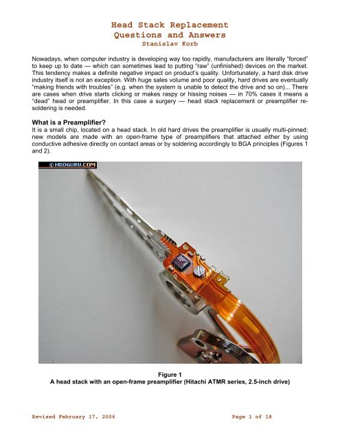
What is a Preamplifier?<br />
It is a small chip, located on a head stack. In old hard drives the preamplifier is usually multi-pinned;<br />
new models are made with an open-frame type of preamplifiers that attached either by using<br />
conductive adhesive directly on contact areas or by soldering accordingly to BGA principles (Figures 1<br />
<strong>and</strong> 2).<br />
Figure 1<br />
A head stack with an open-frame preamplifier (Hitachi ATMR series, 2.5-inch drive)<br />
Revised February 17, 2006 Page 1 of 18
<strong>Head</strong> <strong>Stack</strong> <strong>Replacement</strong><br />
<strong>Questions</strong> <strong>and</strong> <strong>Answers</strong><br />
Stanislav Korb<br />
Figure 2<br />
A frame-type preamplifier (Seagate Barracuda IV drive)<br />
Working with preamplifiers always includes some difficulties, because, practically, they can not<br />
withst<strong>and</strong> static discharges. If re-soldering is needed, one should follow a number of rules to protect a<br />
preamplifier from static damage caused by careless finger touching. Simple protection includes:<br />
ground connections for the drive, for a soldering station, for the repairer; <strong>and</strong> using a 12-volt soldering<br />
station.<br />
How to Tell that it’s Really a <strong>Head</strong> Trouble?<br />
In fact, it is more likely a philosophical question. Even after looking inside the drive there still can be<br />
no definite answer — in this case specialists often count on their own experience <strong>and</strong> on software. For<br />
example, PC-3000 software can accurately detect weak head on IBM, Western Digital, some Seagate<br />
drives, by using service area surface checking functions.<br />
Old hard drives with their obvious reliability (here we mean 20...512 MB drives), are gradually dying;<br />
one of the reasons for that is exactly a heads’ problem. On the Figure 3, a “lifted” head of the 406 MB<br />
Quantum Pro Drive LPS is shown. The “lifted” head is a very serious risk, because it scratches the<br />
platter that can lead to a severe surface damage. Besides being “lifted”, heads can be also plucked<br />
out — it’s been a quite typical trouble for IBM drives. Of course, this trouble doesn’t happen that often,<br />
but if it occurs, an exposed area will be destroyed completely.<br />
Revised February 17, 2006 Page 2 of 18
<strong>Head</strong> <strong>Stack</strong> <strong>Replacement</strong><br />
<strong>Questions</strong> <strong>and</strong> <strong>Answers</strong><br />
Stanislav Korb<br />
Figure 3<br />
“Lifted” head of the 406 MB Quantum Pro Drive LPS<br />
There are also head reading-writing elements failures, which have no indication from outside as well<br />
— these can be detected with an ohmmeter by checking resistance for coils <strong>and</strong> related wires.<br />
A drive can also be clicking if a preamplifier microchip is damaged. It isn’t that simple to detect. For<br />
example, for Seagate drives it will require to attach a drive to a PC COM-port, by using a special<br />
adapter, the schematic (see figure below); <strong>and</strong> by using COM-terminal program, Hyper Terminal for<br />
example. When the drive is powered on, you can see the following message in the terminal:<br />
Interface task reset ........<br />
<strong>Head</strong> Mask 0000 <strong>Head</strong> Mask 0001 <strong>Head</strong> Mask 0002 <strong>Head</strong> Mask 0003<br />
Revised February 17, 2006 Page 3 of 18
<strong>Head</strong> <strong>Stack</strong> <strong>Replacement</strong><br />
<strong>Questions</strong> <strong>and</strong> <strong>Answers</strong><br />
Stanislav Korb<br />
And thus the drive will test all heads from 0 to F; <strong>and</strong> right after that it must come out to level F, or<br />
stop the spindle. The problem of Quantum drives of all series (including last series — known as<br />
Maxtor D540X <strong>and</strong> D740X) can be detected by the specific sounds: after starting, there will be two<br />
loud clicks, then drive’s motor will increase its speed, <strong>and</strong> there will be 4 more clicks, after which the<br />
drive will become “ready”. For Western Digital a dead preamplifier is also detected by the specific<br />
sounds: after two loud clicks the drive will stop the spindle. If you have a clicking Maxtor then heads<br />
malfunctioning is characterized with a continuous clicking for over 30 seconds. Samsung drives with a<br />
dead preamplifier also click two times <strong>and</strong> then stop the spindle; however, for Samsung drives it can<br />
also mean problems with reading of the critical modules of the system area.<br />
<strong>Replacement</strong> of a <strong>Head</strong> <strong>Stack</strong>: Where to Start From?<br />
First of all one should start with a well prepared working place. A key here is — cleanness. Nowadays<br />
recording density is so high that any speck of dust can block from reading several data sectors...<br />
There are different ways to achieve cleanness. The most optimal way is to get or make a “clean<br />
chamber”. It must meet level 10 of cleanness, which means that 1 cubic meter of air must contain no<br />
more that 10 elements of dust. It’s also acceptable to use “clean chambers” with a lower level of<br />
cleanness — everything depends mostly on one’s financial abilities, however, the successful rate of<br />
data recovery procedures will depend exactly on a cleanness factor.<br />
After a clean place is ready we can start with choosing necessary tools (Figure 4).<br />
Revised February 17, 2006 Page 4 of 18
<strong>Head</strong> <strong>Stack</strong> <strong>Replacement</strong><br />
<strong>Questions</strong> <strong>and</strong> <strong>Answers</strong><br />
Stanislav Korb<br />
Figure 4<br />
Tools for head stack replacement<br />
First of all there should be a set of screwdrivers of different types <strong>and</strong> configurations. Then, the<br />
process will require curved <strong>and</strong> straight tweezers. Also a magnifier <strong>and</strong> an office knife will come in<br />
h<strong>and</strong>y. Then, get a good lamp preferably with flexible/changeable light direction <strong>and</strong> a good PC power<br />
supply unit. Finally some alcohol, gloves, a face mask <strong>and</strong> a hair cap should be added: obviously<br />
because a person himself is a big source of dirt — hair (dust) <strong>and</strong> fingers (grease) — therefore it’s<br />
important to protect a drive from all these factors.<br />
So, when a preparation step is completed successfully: all tools are ready <strong>and</strong> a decent level of<br />
cleanness is achieved — we can proceed to replacing a head stack. The first thing one will need here<br />
is — practice.<br />
How to Get some Practice in <strong>Head</strong> <strong>Stack</strong> <strong>Replacement</strong>?<br />
The main requirements for successful head stack replacement are experience <strong>and</strong>, certainly, practice.<br />
For this purpose author suggests finding some dead drives of the same manufacturer, <strong>and</strong> do some<br />
experiments. If after such practice you are confident about your abilities to make head stack<br />
Revised February 17, 2006 Page 5 of 18
<strong>Head</strong> <strong>Stack</strong> <strong>Replacement</strong><br />
<strong>Questions</strong> <strong>and</strong> <strong>Answers</strong><br />
Stanislav Korb<br />
replacement to get the data — then good luck! If you’re still not sure — give more time for practice,<br />
<strong>and</strong> quite soon you’ll get your desirable result!<br />
What are the most important things when making head stack replacement?<br />
1. Take into consideration the rules of head stack compatibility (will be given below).<br />
2. Keep the working place <strong>and</strong> tools clean — tools can be a source of dirt.<br />
3. Don’t hurry, do everything with the maximum accuracy.<br />
4. Under any circumstances do not drink any alcohol or take any substances that can slow down<br />
reaction; it can cause h<strong>and</strong> shaking <strong>and</strong> distraction — most likely the results of your work will be<br />
disappointing.<br />
What is a Donor? And What are the Rules of Compatibility?<br />
The donor is a hard disk drive a head stack which we will use to replace a dead one in the original<br />
drive. The general requirements for choosing donors are: an absolutely identical to the recipient<br />
model type of the camera, identical spindle control <strong>and</strong> VCM chips <strong>and</strong> read/write channel chips.<br />
Besides that, for every manufacturer <strong>and</strong> for many drive series there are specific requirements about<br />
the donor selection — they must be followed in a combination with general requirements (see Table<br />
1).<br />
Yet, even having the same model name, totally identical PCB (drive electronics), we can still be<br />
unpleasantly surprised after having opening the donor — the heads there are different <strong>and</strong> so they<br />
can’t be used for replacing. It is possible to avoid this “surprise” if use characteristics of compatibility,<br />
provided in Table 1; for some drives, besides those characteristics, it is necessary to check a serial<br />
number which gives information about the number of heads. It is very useful, especially for Maxtor<br />
drives. For example, author has seen Maxtor 6Y120L0 hard drives (120 GB) with 3, 4 <strong>and</strong> even 5<br />
heads. It is possible to define the number of heads by looking at the serial number for Maxtor,<br />
Quantum <strong>and</strong> Seagate hard disk drives (Figure 5, 6, 7), namely:<br />
Figure 5<br />
Serial number of Maxtor 7Y250P0 (250 GB). The second character of the serial number st<strong>and</strong>s<br />
for the quantity of installed <strong>and</strong> being used heads<br />
Revised February 17, 2006 Page 6 of 18
<strong>Head</strong> <strong>Stack</strong> <strong>Replacement</strong><br />
<strong>Questions</strong> <strong>and</strong> <strong>Answers</strong><br />
Stanislav Korb<br />
Figure 6<br />
Serial number of Quantum Plus AS (40 GB). The third symbol of the serial number shows the<br />
quantity of installed <strong>and</strong> being used heads<br />
Figure 7<br />
A serial number of Seagate Barracuda 7200.7 ST3200822A (200 GB). The third symbol of the<br />
serial number represents the quantity of installed <strong>and</strong> being used heads<br />
Looking for donors for these drives one should also check an identical firmware revision or identical<br />
symbols in the alphanumeric codes on the labels.<br />
Table 1: The Characteristics of Donor Drive Compatibility for <strong>Head</strong> <strong>Stack</strong> <strong>Replacement</strong><br />
Family/Manufacturer Firmware Country Part<br />
Number<br />
Other Characteristics<br />
Maxtor (all families) + + - Third character in alphabetic code type<br />
X, X, X, X should match<br />
Fujitsu (all families) - + - First character in firmware revision (xx-<br />
Xxxx) should match<br />
IBM (up to AVER family) + + +<br />
IBM (after AVER) + + + There is a strict relation between a head<br />
stack type <strong>and</strong> MLC code, so MLC code<br />
must be identical<br />
Hitachi 3.5' + - + CPU firmware revision should match<br />
Hitachi 2.5' - + - PCB revision match is m<strong>and</strong>atory<br />
Quantum (up to Plus AS family) + - -<br />
Quantum Plus AS, D540X, D740X + + - The alphabetic code on the HA must be<br />
identical<br />
Toshiba - + -<br />
Revised February 17, 2006 Page 7 of 18
<strong>Head</strong> <strong>Stack</strong> <strong>Replacement</strong><br />
<strong>Questions</strong> <strong>and</strong> <strong>Answers</strong><br />
Stanislav Korb<br />
Fujitsu 2.5' + + -<br />
Western Digital + - - In the alphabetic DCM code the sixth<br />
(<strong>and</strong> quite desirably the fifth) characters<br />
must be identical<br />
Samsung - + - Forth character in the alphabetic code<br />
printed on the label at the rear side od<br />
the drive should match<br />
Seagate + + -<br />
Drives of the same family can be modified by the manufacturer, therefore given recommendations<br />
should be followed strictly.<br />
Figure 8<br />
Seagate Barracuda 7200.7, 40 GB. Firmware 3.06, one head is on the upper side of the surface<br />
Revised February 17, 2006 Page 8 of 18
<strong>Head</strong> <strong>Stack</strong> <strong>Replacement</strong><br />
<strong>Questions</strong> <strong>and</strong> <strong>Answers</strong><br />
Stanislav Korb<br />
Figure 9<br />
The same drive with a plastic airlock visible<br />
Figure 11<br />
An old ST3660A <strong>and</strong> its vulnerable place — plastic limiter<br />
Revised February 17, 2006 Page 9 of 18
<strong>Head</strong> <strong>Stack</strong> <strong>Replacement</strong><br />
<strong>Questions</strong> <strong>and</strong> <strong>Answers</strong><br />
Stanislav Korb<br />
What is a Refurbished Drive? Can it be Used as a Donor?<br />
The purpose of refurbished drives is to utilize broken devices by using them for the second cycle while<br />
changing some parameters, disconnecting bad heads, changing firmware revision, etc. As examples<br />
of mass refurbishing we can mention drives Maxtor N40P series with a body taken from Maxtor Ares<br />
C64K, they have NAR61EA0 firmware revision; or Western Digital EB <strong>and</strong> BB series with the letter “R”<br />
in the serial number. Obviously, if a refurbished HDD is going to be built from the drive that has a bad<br />
system head (head number 0, the bottom one), this head will not be disconnected, but instead of it<br />
another one will become active <strong>and</strong>, accordingly, the firmware revision will be changed (e.g. for<br />
Seagate Barracuda 7200.7 there are several firmware revisions — 3.53, 3.75, 8.75 — where only a<br />
couple heads of the whole number are being used. Changing the head stack is never happens in<br />
factory repairs; instead, the manufacturer uses already available sources.<br />
One more factor is the adaptive parameters, which are calculated for particular head stack type, PCB<br />
<strong>and</strong> camera, <strong>and</strong> therefore are unique. Lack of coincidence between adaptive parameters in the<br />
system area of the recipient drive will not allow getting the quality data from it; moreover, this can<br />
cause clicking. Therefore, it can be said with confidence, that refurbished drives are of little use as<br />
head stack donors — there is quite high possibility that those heads will not accommodate well on a<br />
new place.<br />
<strong>Head</strong>s load/unload System<br />
Practically there aren’t that many types of heads load/unload systems. Roughly, they can be sorted<br />
into an “external” type systems (heads are parked outside the platters), <strong>and</strong> internal type (heads are<br />
parked directly on the platters in a special parking zone).<br />
The external load/unload system is being used in all modern 2.5-inch drives since it is much safer.<br />
Besides that, it is being used in IBM <strong>and</strong> Hitachi 3.5-inch drives (Figures 12—14). The external<br />
load/unload system can be also found in SCSI hard drives — with up to 12 heads being unloaded!<br />
Figure 12<br />
A load/unload zone with unloaded heads (IBM AVER series, 40 GB)<br />
Revised February 17, 2006 Page 10 of 18
<strong>Head</strong> <strong>Stack</strong> <strong>Replacement</strong><br />
<strong>Questions</strong> <strong>and</strong> <strong>Answers</strong><br />
Stanislav Korb<br />
Figure 13<br />
<strong>Head</strong>s are loaded onto the surface (Hitachi AVV2 series hard drive, 80 GB)<br />
Figure 15<br />
Surface damage caused by a damaged head<br />
Revised February 17, 2006 Page 11 of 18
<strong>Head</strong> <strong>Stack</strong> <strong>Replacement</strong><br />
<strong>Questions</strong> <strong>and</strong> <strong>Answers</strong><br />
Stanislav Korb<br />
The internal load/unload system can be of a mechanical structure type; this type is widely common for<br />
Seagate hard drives of new series, Quantum hard drives (Figures 9, 16, 17) <strong>and</strong> slim Maxtor drives<br />
which have quite complex plastic mechanical structure of their load/unload system (Figure 18).<br />
A load/unload system of Quantum HDD<br />
Figure 16 — Quantum Maverick. Figure 17 — Quantum Fireball LCT10<br />
Revised February 17, 2006 Page 12 of 18
<strong>Head</strong> <strong>Stack</strong> <strong>Replacement</strong><br />
<strong>Questions</strong> <strong>and</strong> <strong>Answers</strong><br />
Stanislav Korb<br />
Figure 18<br />
A load/unload system of (thin) Maxtor Athena, Nike, N40P, Ares C64K series<br />
The performance of a load/unload system in full-size Maxtor drives, also in Fujitsu <strong>and</strong> Western Digital<br />
hard drives is based on a magneto-mechanical principle. A head is pulled by a magnet attached to a<br />
limiter; the head is pulled to a special projection in the positioner’s structure which itself is quite simple,<br />
but has one drawback: a strong electromagnetic pulse is needed to load the heads — <strong>and</strong> with some<br />
types of PCB malfunctions it can become impossible for heads to load; besides that, there are<br />
chances of damaging a VCM coil when giving that electromagnetic pulse (e.g. short circuits in a coil<br />
have been seen, for example, in Maxtor hard drives of Calypso series).<br />
Revised February 17, 2006 Page 13 of 18
<strong>Head</strong> <strong>Stack</strong> <strong>Replacement</strong><br />
<strong>Questions</strong> <strong>and</strong> <strong>Answers</strong><br />
Stanislav Korb<br />
Figure 20<br />
A load/unload system with a magneto-mechanical principle (WD200EB)<br />
Why <strong>Head</strong>s are Numbered Starting from Zero?<br />
There is a simple reason for that — everything which is related to electronic devices is guided by<br />
mathematical laws. In mathematics — 0 is still a number like 1 or 100, <strong>and</strong> in decimal format or<br />
hexadecimal (HEX) zero starts the numerical row. Traditionally in HDD manufacturing a HEX format is<br />
used because of several reasons — one of them is explaining that to determine big numbers you<br />
need less characters (e.g. number 255 will be given in hexadecimal format as FF); besides that, a<br />
st<strong>and</strong>ard two-byte word makes 16 bit, which has also become a reason for choosing HEX format.<br />
<strong>Head</strong>s are counted starting from a lower (bottom) head — the lowest one has number 0, the next<br />
following has number — 1, <strong>and</strong> so forth (Figure 21). It should be noticed that even when heads are<br />
physically missed, they are still given the numbers (Figure 22). On the Figure 21 (a damaged head<br />
stack of WDE9180) it is shown that the numeration starts from head 2 <strong>and</strong> we can see that two lower<br />
heads are missed.<br />
Revised February 17, 2006 Page 14 of 18
<strong>Head</strong> <strong>Stack</strong> <strong>Replacement</strong><br />
<strong>Questions</strong> <strong>and</strong> <strong>Answers</strong><br />
Stanislav Korb<br />
Figure 21<br />
A heads numbering scheme (SCSI Western Digital)<br />
Figure 22<br />
A head stack (WD600BB) — heads number 0, 1 <strong>and</strong> 3 are physically present; head number 2 is<br />
missed<br />
Revised February 17, 2006 Page 15 of 18
<strong>Head</strong> <strong>Stack</strong> <strong>Replacement</strong><br />
<strong>Questions</strong> <strong>and</strong> <strong>Answers</strong><br />
Stanislav Korb<br />
What Particular Features should be Considered in <strong>Head</strong>s <strong>Replacement</strong>?<br />
Ground Yourself!<br />
Now, let’s get down to the main question — how to do heads replacement? First, we need to pick a<br />
donor. It may happen that we will need more than one donor — when surfaces are damaged so much<br />
that, during the reading process, heads literally “burn out”. As the examples of cases when more than<br />
one donor is required we can mention hard drives Quantum Plus AS <strong>and</strong> Maxtor D540 — D740X.<br />
Next step — we clean up the donor <strong>and</strong> the recipient, better off by applying an alcohol on their bodies<br />
<strong>and</strong> PCBs — the main source of dirt is here. Then we put them into a “clean chamber” <strong>and</strong> start the<br />
process. If a drive has screws that fix the spindle <strong>and</strong>/or head stack on the lid, they must be released<br />
first. Only after that we can move to the remaining. Now, we have the drive opened. To take out<br />
malfunctioning heads we need to partially disassemble some internal parts of the drive.<br />
It’s recommended to start with an upper magnet of a position control system. Take off all screws that<br />
hold it, then grip the magnet by pliers <strong>and</strong> take off the magnet. Note that magnets are very strong <strong>and</strong><br />
in case if it slips out — the hit will be very strong <strong>and</strong> consequences unpredictable.<br />
After taking off the upper magnet we can see a VCM coil <strong>and</strong> a position control system (Figure 23).<br />
Now we have to remove screws that hold the connector (on Figure 23 — in the upper right corner of<br />
camera). Only after that we take off the elements of a load/unload system. If your hard drive has an<br />
internal load/unload system, then you should take the heads out of it first (move them through the<br />
platters), while doing this you should spin the platters, <strong>and</strong> without stopping spinning move the heads<br />
outside the platters.<br />
Figure 23<br />
An inside structure of a position control system (Seagate Barracuda 7200.7, 160 GB): a head<br />
stack, a VCM coil, the load/unload mechanisms<br />
Revised February 17, 2006 Page 16 of 18
<strong>Head</strong> <strong>Stack</strong> <strong>Replacement</strong><br />
<strong>Questions</strong> <strong>and</strong> <strong>Answers</strong><br />
Stanislav Korb<br />
Why is it needed to spin platters when moving heads? The answer is simple: heads can stick to the<br />
surface if moving without spinning.<br />
Before taking heads out of platters, we should take measures for them not to stick together. If there is<br />
only one head — no worries, but if there is more than one — then paired heads in the block can stick<br />
together. To prevent this we can put one of the paired heads in a special container. The author uses<br />
thin drink straws that can be prepared next way: a straw is heated up to the level that is close to its<br />
melting temperature, after that the straw is flattened to a desired form (for example, by putting a ruler<br />
on it <strong>and</strong> waiting until the straw gets the right form). Then the straw can be cut into pieces which will<br />
be used for packing the heads. We can apply the same method for storing used heads.<br />
If a drive has more than two heads then to pack the difficult-of-access heads from a lower levels<br />
properly we will need thin curved plastic tweezers.<br />
So, the heads are moved out <strong>and</strong> packed. Now we release the screw that holds the axis of a head<br />
stack, <strong>and</strong> carefully, by moving directly up, we are pulling the head stack off. During this procedure it<br />
is very important to remember that a head stack can not withst<strong>and</strong> static discharge, <strong>and</strong> therefore, it<br />
will be ideal if you are working being grounded <strong>and</strong> using gloves. A head stack must be pulled off by<br />
using tweezers or combination pliers — taking a head stack by h<strong>and</strong>s can cause damage to wires<br />
which coming from the preamplifier to the read-write elements.<br />
Having done the same procedure to a donor we will get a set of good heads which we can place into<br />
our recipient drive. We will start with putting a head stack on the axis by using tweezers or<br />
combination pliers, <strong>and</strong> then tighten the screw.<br />
Next step — loading heads on the surface. That is actually the most difficult part. If there is 1 head or<br />
2 heads — it will be done easily by moving the heads apart using tweezers. In case of more than 2<br />
heads we will need either ten h<strong>and</strong>s or a special tool for moving the heads apart — from this point<br />
everything will depend on your imagination <strong>and</strong> how you would like to do this; the author uses paired<br />
tweezers <strong>and</strong> plastic straws for this purpose.<br />
After heads have been placed on the surfaces, we are accurately moving heads towards the parking<br />
zone while spinning the platters. For drives that have an external load/unload ramp it is needed first to<br />
put back the ramp. If during the loading process you hear any strange sound — creak, scratch-like<br />
sounds, you need to move heads out again <strong>and</strong> check the accuracy of all steps. If you decide to leave<br />
it as is, the drive will spin up <strong>and</strong> then, most likely, heads will damage the surface.<br />
Have already moved heads on their place without incidents? Well done! Now we put back all internal<br />
stuff, <strong>and</strong> then move to a next difficult step — putting back an upper magnet. To complete this task we<br />
fix the drive tightly, grip the magnet by pliers <strong>and</strong> carefully put the magnet back on its place. When it is<br />
finally placed, we correct its position <strong>and</strong> fasten the screws back, <strong>and</strong> after that we can turn on the<br />
drive. If everything is done correctly <strong>and</strong> with decent accuracy — the drive will recalibrate, be detected,<br />
<strong>and</strong> we will see our data.<br />
What is to be Done about Western Digital EB <strong>and</strong> BB?<br />
Indeed, those drives are a sort of “evil” stuff. Their head stack axis is fixed by the lid, therefore if<br />
heads had been taken out it is impossible to reconstruct the original position of the fixing screw, <strong>and</strong><br />
such drive hardly ever starts well after head stack replacement. However, there is one fortunate point<br />
— the BPI density is quite low for those drives, <strong>and</strong> this allows copying data from an open drive. Of<br />
course, while maintaining a good level of cleanness.<br />
Revised February 17, 2006 Page 17 of 18
<strong>Head</strong> <strong>Stack</strong> <strong>Replacement</strong><br />
<strong>Questions</strong> <strong>and</strong> <strong>Answers</strong><br />
Stanislav Korb<br />
We have the heads swapped, then, with a screwdriver inserted into the axis, we are trying to find such<br />
position of the axis when the drive can recalibrate <strong>and</strong> give access to the data (Figure 25). Next, for<br />
some time (can be easily up to one hour) we will have to sit <strong>and</strong> hold the screwdriver in that position<br />
— but the job is worth it!<br />
Figure 25<br />
After heads had been replaced, author would have to adjust manually a gradient angle of a<br />
head stack axis in WD200BB hard drive to get data<br />
Revised February 17, 2006 Page 18 of 18